Embed Size (px)
Citation preview

1
WHOLE CELL INTEGRATED WHOLE CELL INTEGRATED BIOBIO--CHIPCHIP
Yosi Shacham-Diamand

Tel-Aviv University, May 11, 2004
Whole-cell biochips for early detection of water
poisoning
Whole-cell biochips for early detection of water
poisoning

Yosi Shacham-Diamand
Tel-Aviv University Research InstituteFor Nano-Science and Nano-Technologies
Yosi Shacham-Diamand
Tel-Aviv University Research InstituteFor Nano-Science and Nano-Technologies

4
THE THREAT: Intentional poisoning of a drinking water source
THE NEED: A rapid broad-spectrum early warning device
Statement by Homeland Security Secretary Tom Ridge on Raising the Threat Level
For Immediate ReleaseOffice of the Press SecretaryMay 20, 2003
The Department of Homeland Security, in consultation with the Homeland Security Council, has made the decision to raise the national threat level from an Elevated to High risk of terrorist attack or Level Orange.
No such device exists today!No such device exists today!

How do we detect the presence of toxic
compounds in a water sample?
The obvious answer:
Chemical analysis
* Highly accurate and sensitive* Requires complex analytical
equipment* May be lengthy and costly
An alternative approach:
Toxicity bioassays
* Not “what does the sample contain”?, but“how toxic is the sample”?

TOXICITY BIOASSAYS
Standard toxicity bioassays, mostly designed for environmental purposes, are unsuitable for our needs.
They cannot answer the question:
“is the water safe to drink?”

Our solution: cell-based biosensorsOur solution: cell-based biosensors
Rather than use whole animals, we can genetically engineer live cells to emit a signal in the presence of toxicants

8
Human cell systems, assay screening:Ministry of Health, National Public Health LaboratoriesIsrael Laboratory Accreditation AuthorityDr. Efrat RormanDr. Orna Dreazen
æºØ
fił¢ª
ø¢łÆØ œ ØłÆ œØ ł
ªÆ
PUBLIC HEALTH LABO
RATO
RIES
Microbiology, yeast systems:Hebrew University of JerusalemProf. Shimshon BelkinDr. David Engelberg
Micro-System-Technology (MST) and integration :Tel-Aviv UniversityProf. Yosi Shacham-Diamand Prof. Yoram Shapira
Risk assessment and decision support models development:Israel Defense Forces, Medical CorpLieutenant Colonel Patrick BettaneDr. Lt. Colonel Yoav YehezkeliDr. Colonel Boaz Tadmor Dr. John S. Young, HUJ, Consultant

9
Cell-based toxicity sensor chipsCell-based toxicity sensor chips
Live cells, genetically engineered to emit a signal in the presence of toxicantsIncorporated into a disposable biochip that provides:
Live cell maintenanceMicrofluidics for sample introduction
The biochip is inserted into a Toxicity Analyzer that contains:
Electronic control and operation circuitsDetection opticsTemperature controlLogic circuits and decision algorithmsCommunication capacities

10
The final construct emits a dose-dependent signal in response to the presence of the target chemicals
The fusion of two genetic elements:The fusion of two genetic elements:
Light
gene promoter
Sensing element
luxCDABE
Reporting element
Engineering live cells for the detection of toxicants
Sensing element: A promoter of a gene involved in the response to the desired target
Reporting element: Fluorescence or bioluminescence genes

11
Liquid fireflies

12

Bacterial systems (E. coli)* Facilitated genetic manipulation* Proven concept validity* Limited relevance to human health
Human cell systems (liver, neuronal)* Maximum hum an exposure relevance* A much more complex technical challenge
Yeast cells (S. cerevisiae)* Eukaryotic structure and function* Relative facility in genetic manipulation
The original grand plan - three types of sensor cellsThe original grand plan - three types of sensor cells
14
Human cell constructs
Feasibility of engineering human and yeast cell systems has beendemonstrated, but performance is not yet in the required range
Clone # 43
Yeast constructs
No Induction 0.03ppm Cd++ Heat Shock
Clone # 31
No Induction 0.03PPM Cd++ 20PPM DDVP Heat Shock

15
YEGFP reporter is induced and quantitatively measurable in yeast
Bright Field
Fluorescence
0
5000
10000
15000
20000
25000
30000
35000
40000
Rel
ativ
e in
tens
ity
X 1
000
Uninduced(Dextrose)
Induced(Galactose)

16
Transient TransfectionNeuroblastoma & Inducible
GFP
Induced
Bright Field
Fluorescent light
Non-induced
Induced Stable HepatomaClones
Promoter: HSP70BReporter: EGFP
Clone No. 8
Clone No. 12

17
Hepatopa cells, clone 8Response to a mixture of
Metals(including 0.056ppm Cd)
14 h exposure
Hepatoma Cells on a Chip Model
Confluent Monolayer Cells at the Edge
18
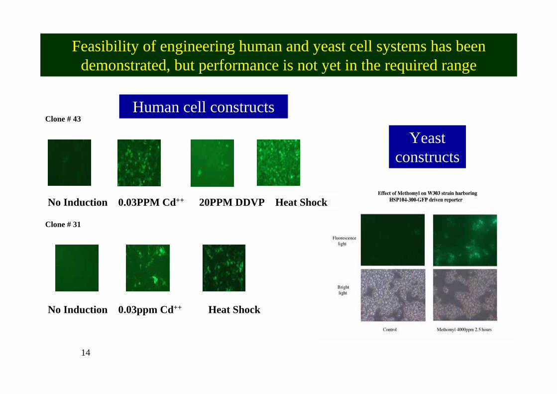
Obtaining a successful bacterial GFP induction in small volumes
Absolute protection against dryingPhysiological condition of cellsAppropriate cell density
0
2 104
4 104
6 104
8 104
0 100 200 300 400 500 600 700
FLU
OR
ES
CE
NC
E (R
FU)
TIME (min)
2 µl cell suspension
2x10⁵ cells, recA::EGFP
Using bacterial systems we demonstrated dose-dependent responses to all target compounds so far tested, at or close
to the required detection thresholds
Using bacterial systems we demonstrated dose-dependent responses to all target compounds so far tested, at or close
to the required detection thresholds

190
10
20
30
40
50
60
70
80
Res
pons
e R
atio
lpxA
rfaDFCL
arcAlacAYZ
yigH
yhaN
nhoA
Choice of promoters

20
For maximizing the detection range and enhancing analysis potential: a panel of
sensor strainsor
aA
nhoA
mip
A
lacA
YZ
grpE
MethomylDDVP
N-MustardKCNParathionParaquat
0
10
20
30
40
50
60
Res
pons
e R
atio
oraA
nhoA
mip
A
lacA
YZ
grpE
MethomylDDVP
N-MustardKCNParathionParaquat
0
10
20
30
40
50
60
Res
pons
e R
atio

21
Panel response patternPanel response pattern
30 min 60 min 120 min
grpE
nhoA
oraA
lacZ
mipA
nitrogenmustard ethyl
paration paraquatpotassiumcyanide DDVP
sterile LB
0
50,000
100,000
150,000
200,000
250,000
grpE
nhoA
oraA
lacZ
mipA
nitrogenmustard ethyl
parathion paraquatpotassiumcyanide DDVP
sterile LB
0
10,000
20,000
30,000
40,000
50,000
60,000
grpE
nhoA
oraA
lacZ
mipA
nitrogenmustard ethyl
parathion paraquatpotassiumcyanide DDVP
sterile LB
0
2,000
4,000
6,000
8,000
10,000
12,000
14,000
16,000
ABC
grpE
nhoA
oraA
lacZ
mipA
nitrogenmustard ethyl
paration paraquatpotassiumcyanide DDVP
sterile LB
0
50,000
100,000
150,000
200,000
250,000
grpE
nhoA
oraA
lacZ
mipA
nitrogenmustard ethyl
parathion paraquatpotassiumcyanide DDVP
sterile LB
0
10,000
20,000
30,000
40,000
50,000
60,000
grpE
nhoA
oraA
lacZ
mipA
nitrogenmustard ethyl
parathion paraquatpotassiumcyanide DDVP
sterile LB
0
2,000
4,000
6,000
8,000
10,000
12,000
14,000
16,000
ABC
22
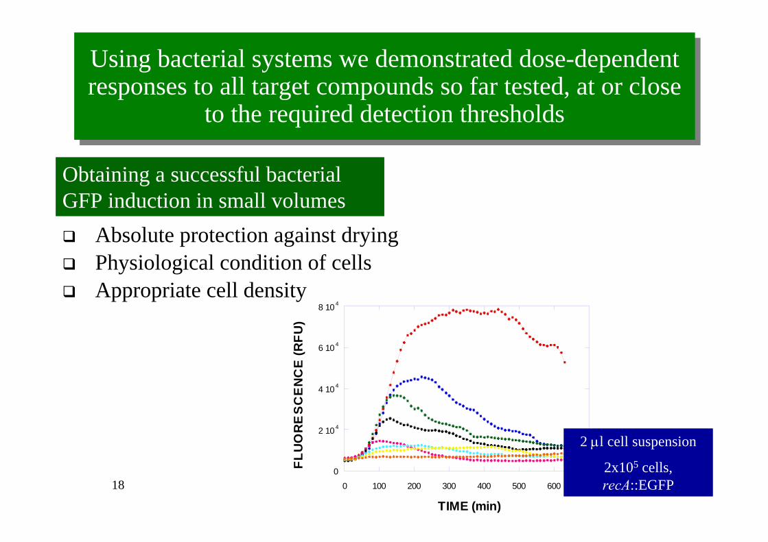
Chemical TDC(mg/l)# Concentration detected (mg/L)*
Paraquat 5,250 0.43
Potassium Cyanide 230 0.2
E-Parathion 70 13.0
DDVP 1,960 32.5
N-Mustard 350 6.1
2,4,5-Trichlorophenol 2,960 0.8
2,6-Dichlorophenol 6,550 1.2
2-Chlorophenol 12,110 2.8
Colchicine 203 14.3
Phosdrin 170 38.3
Metham Sodium 28,700 18
#) Chemical concentration needed to be present so that a 70 Kg person, consuming 2 liters of water, will be exposed to the published LD50 value (oral, Rat). The reporter’s detection threshold will need to be much lower then this number, as is indeed the case in most chemicals tested.
*) Concentration generating a 2:1 signal to noise ratio.
Sample detection thresholdsSample detection thresholds

23
We believe we can “tailor” our sensors to
respond to any group of toxicants, thus ensuring an unprecedented broad spectrum of bio-detection

24
Effect of Botulinum Toxin
0
5000
10000
15000
20000
25000
0 100 200 300Tim e (m in)
RLU
0.5m g/L0.250.1250.060.030.0150.0750
Effect of Botulinum Toxin Concentration
0.00
5000.00
10000.00
15000.00
20000.00
25000.00
0 0.05 0.1 0.15
Botulinum (m g/L)
RLU
The search for additional promoters
Preliminary responses to Botulinum toxin
25
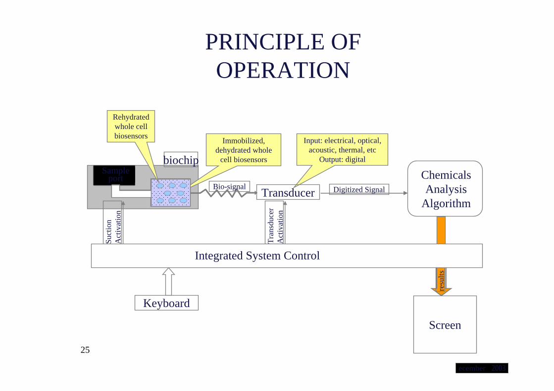
PRINCIPLE OF OPERATION
Tran
sduc
er
Act
ivat
ion
resu
lts
biochipSample
portReaction Chamber
Water with ChemicalsSample
port
Suct
ion
Act
ivat
ion
Input: electrical, optical, acoustic, thermal, etc
Output: digital
Immobilized, dehydrated whole
cell biosensors
Rehydratedwhole cell biosensors
TransducerChemicals Analysis
Algorithm
Keyboard
Screen
Integrated System Control
Digitized SignalBio-signal
ecember 2003

26
Data Presentation &
Processing
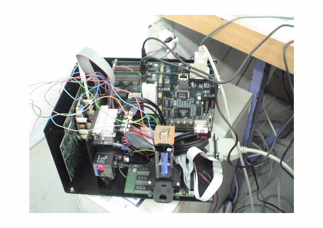
Integrated System Prototype
Experimental System
Biochip Inserter
Biochip
Control Communication Link
Fast Communication Link
Blue light source
Emission filter
Video-
ControlModule
Temp.control
MEMS
Blue light source
Excitation filter
Video-cameraImage Sensor
Bio-SensorsWater channel uPumps activation
temperature control
intensity control
Sample portuPump
Emission optics Control Comm. Link
Fast Comm. Link
December 2003
27

28
Putting the components together for a functional toxicity detection biochip
Putting the components together for a functional toxicity detection biochip
Background
Actual chip
Chip design
Toxic sampleNeutral sample
Quantification
29
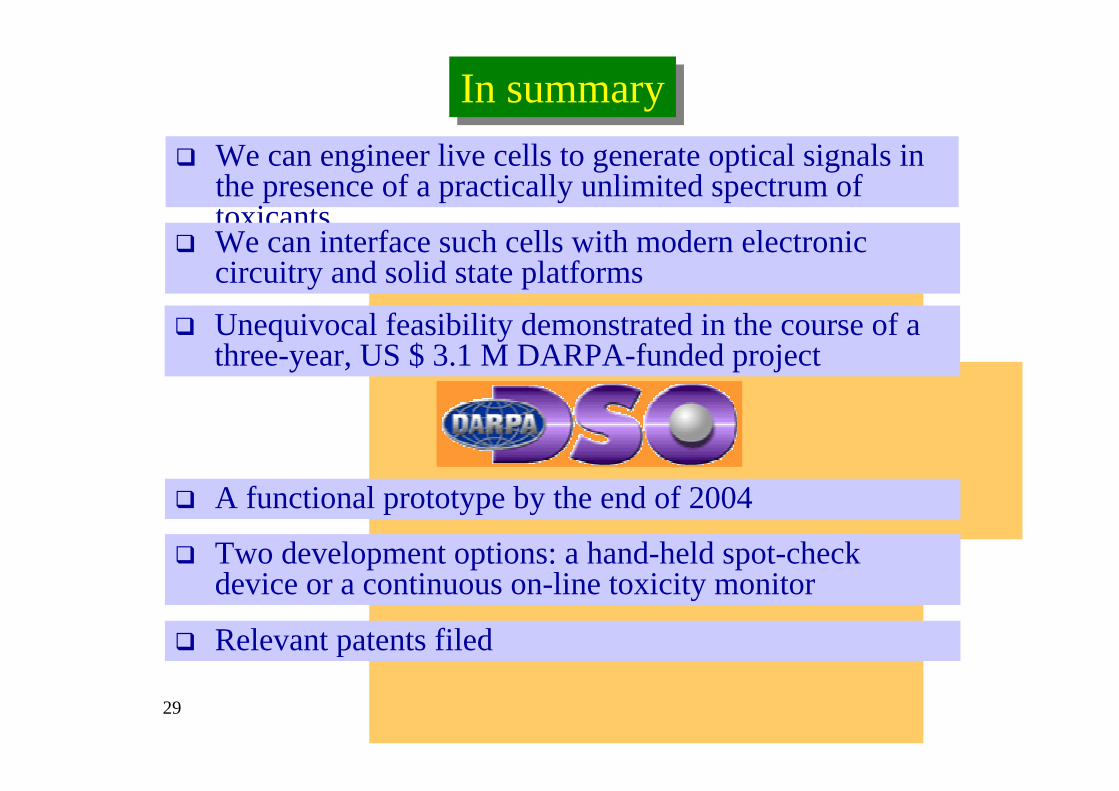
We can engineer live cells to generate optical signals in the presence of a practically unlimited spectrum of toxicants
In summaryIn summary
We can interface such cells with modern electronic circuitry and solid state platformsUnequivocal feasibility demonstrated in the course of a three-year, US $ 3.1 M DARPA-funded project
A functional prototype by the end of 2004
Two development options: a hand-held spot-check device or a continuous on-line toxicity monitor
Relevant patents filed

30
Acknowledgements
• Thanks to Dr. Colonel Boaz Tadmor(Medical Corps, IDF) whose
contribution was invaluable in getting DARPA involved.
• Thanks to all the students and researchers who are involved in this project.

31
Part II
• The electronics technology of bio-sensing

32
Table of Contents:IntroductionWhole cell biochips:
The signal source: Whole cell Biosensors on a microfluidicschip
Light emitting sources: Photoluminescent, BioluminescentElectrical sources: Electrochemical
The detectors: solid state photo-detectorsArrays – Diode arrays, CMOS, CCDSingle detectors: photodiodes, photo-multipliers
Example – Whole cell integrated systemSource - E. Coli integrated on chipDetector – CMOS array
Summary and conclusions

33
Motivation: cells can be integrated on a chipMotivation: cells can be integrated on a chipCells dimensions:
• Mammalian cells ~10-20 µm (typical)• Bacteria cell: ~ 0.1 – 10 µm
Biochip dimensions:
• Components ~1 – 1000 µm
• Chips ~1 mm – few cm

34
Motivation: cells can be integrated on a chipMotivation: cells can be integrated on a chip
New technologies became available: Micro-fluidics
- fluid systems on a chip using Micro-machining
Microelectronics - compatible with the micro-fluidics
Low power detectors - can be integrated with cells on chip

35
Why integrating live cells ?
Multi-cells:
Functional response
Emulating “real” life behavior
Emulating complex systems characteristics
Study cell behavior
Single cells:
All the above + cell sorting

36
Photograph from the "Welsh Coal Mines" Collection from the National Museum of Wales
The The ““Canary in Canary in a cagea cage”” conceptconcept

37
: Schematic outline of the integrated cell-based bio-chip.
Disposable Unit Nondis posable Unit
Sense & Data Analysis UnitWater inlet Toxicity InformationµFluidic
Sys tem
Cells chambers
38
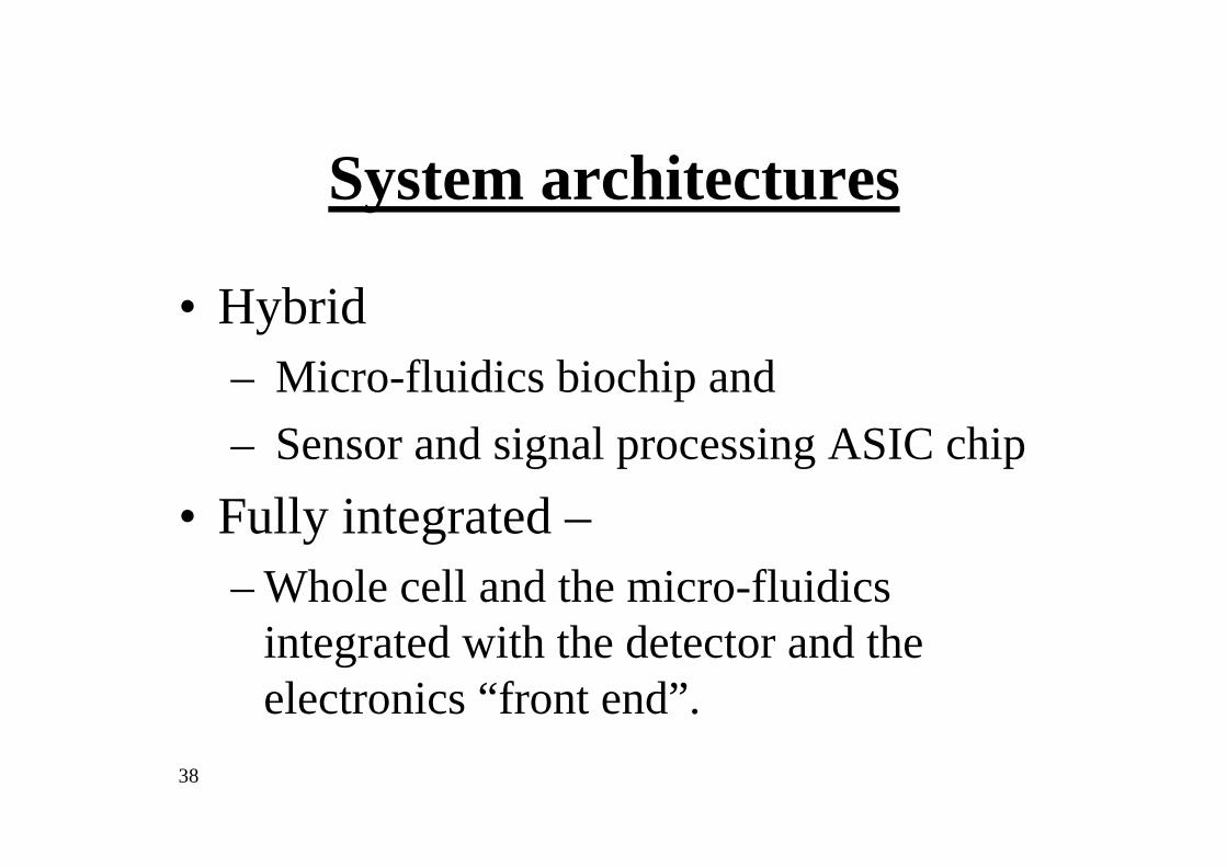
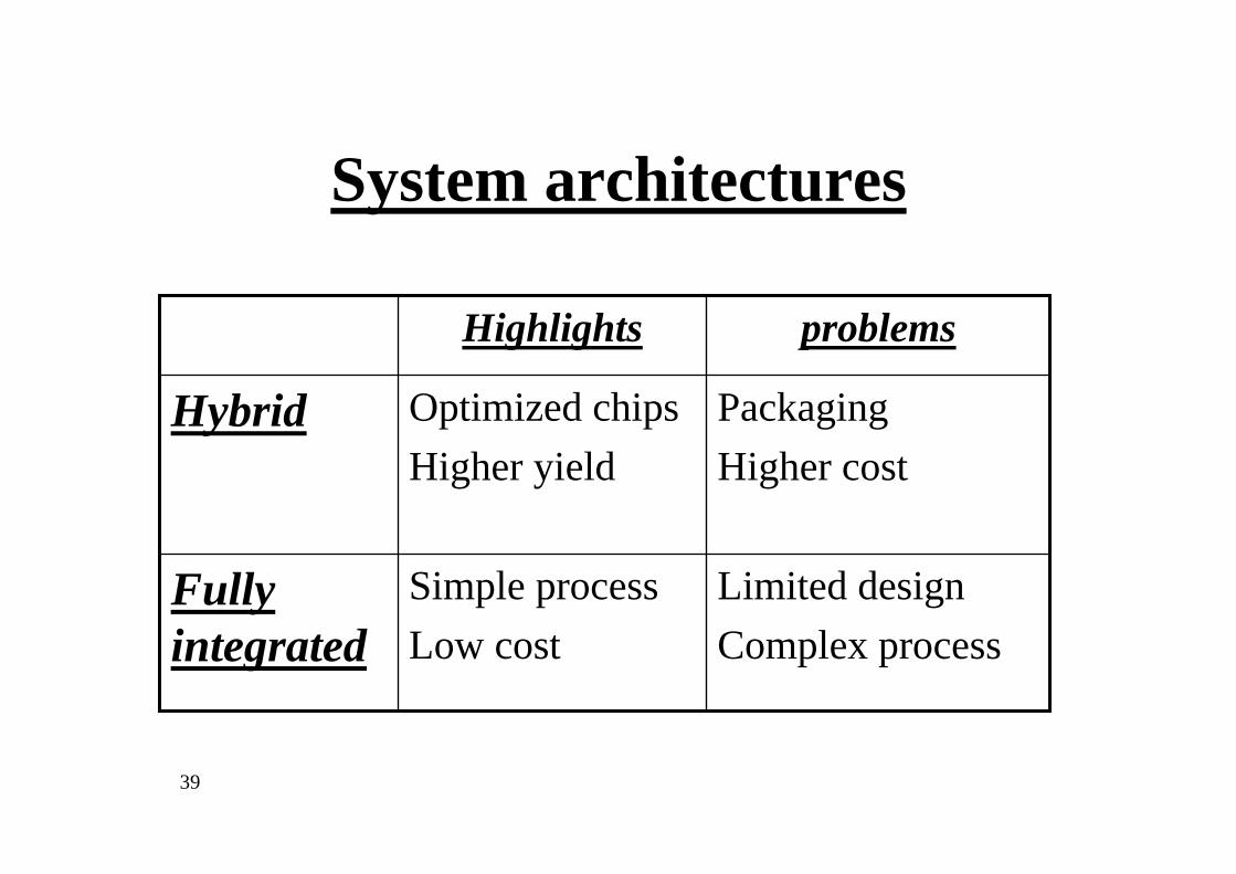
System architectures
• Hybrid– Micro-fluidics biochip and – Sensor and signal processing ASIC chip
• Fully integrated –– Whole cell and the micro-fluidics
integrated with the detector and the electronics “front end”.
39
System architectures
Limited designComplex process
Simple processLow cost
Fully integrated
PackagingHigher cost
Optimized chipsHigher yield
Hybrid
problemsHighlights

40
MST scale: Micro-fluidics systems
Micri-pump made by MST (also known as
MEMS)
Micro-pump cross section
41
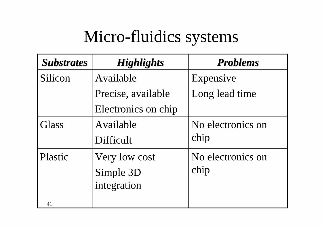
Micro-fluidics systems
No electronics on chip
Very low costSimple 3D integration
Plastic
No electronics on chip
AvailableDifficult
Glass
ExpensiveLong lead time
AvailablePrecise, availableElectronics on chip
SiliconProblemsProblemsHighlightsHighlightsSubstratesSubstrates
42
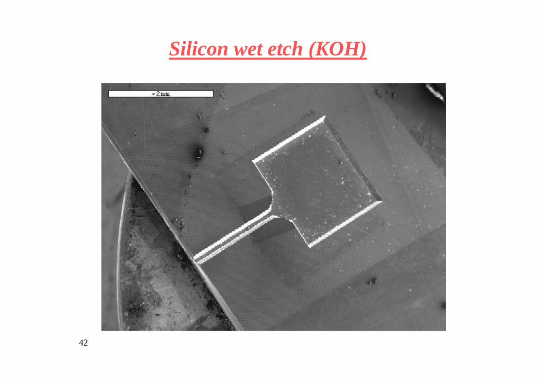
Silicon wet etch (KOH)

43
Silicon wet etch (KOH)

44
Silicon dry etch (ICP)

45
Optical signal
a. Low signala. Simpleb. Fast
Bioluminescence
a. Requires;1. Illuminator2. Transparent substrateb. λexitation~ λemission
c. Slow
Large signal at will
PhotoluminescenceProblemsHighlights

46
Light signal: Photo luminescent
Biosensor Cell
GFP
Modified DNAPromoter
toxicant
GFP
GFP
GFP
GFP
Plasmid
Modified DNA
Plasmid

47
Electrical signal: electrochemical

48
(a) Chip masks formed using standard CAD tools. (b) Two electrochemical cells, each containing three electrodes and
pads. (c) SEM picture of the electrochemical cell.

49
Example:
E. coli producing β-galactosidase, entrapped in agar media coupled to the chip surface was monitored by amperometric technique (V=220mV). The oxidation current observed is generated by the enzyme activity.
It is based on the work of Prof. Yehudit Rishpon on large scale cell containers at Tel-Aviv University that was applied to a biochip with volumes in the range of 100-1000 nL.

50
Current from bacteria producing β-galactosidase in thin layer LB-agar (1.8%) medium placed on the chip surface following addition of PAPG substrate. .
0.00E+00
2.00E-08
4.00E-08
6.00E-08
8.00E-08
1.00E-07
1.20E-07
1.40E-07
1.60E-07
0 500 1000 1500 2000 2500 3000
Time, sec
I, A
mpe
r
Agar with bacteia Agar without bacteria

51
Electrical signal: electrical

52Joseph J. Pancrazio, Center for Bio/Molecular Science and Engineering Naval Research Laboratory Washington, DC, Proc. WTEC workshop 2000.
Single cell integration
53
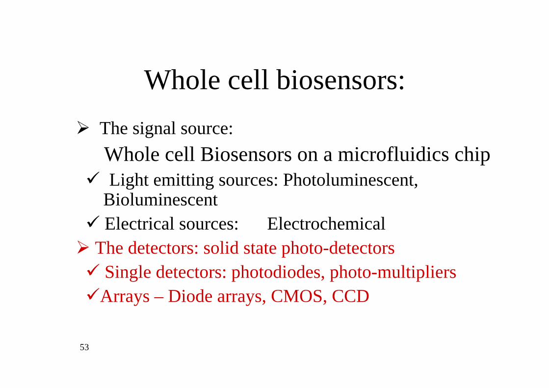
The signal source: Whole cell Biosensors on a microfluidics chipLight emitting sources: Photoluminescent,
BioluminescentElectrical sources: Electrochemical
The detectors: solid state photo-detectorsSingle detectors: photodiodes, photo-multipliers
Arrays – Diode arrays, CMOS, CCD
Whole cell biosensors:

54
The signal problem from a biochip
1. Weak signals emitted to 4π, low signal to noise ratio
2. Spatial nonuniform signal
3. Complex optics – molecular sources in liquid in micro-containers with many reflecting surfaces.
4. Require miniaturized optics – micro-machined or micro-coupled.
5. Difficult temperature control– both of the sources (cells) and the detectors (Solid state)

55
Integrated Solid state detectors
• Single detectors – photodiodes, avalanche photodiodes, photomultipliers
• Detector arrays – CMOS imagers, CCDs

56
Single detectorsSingle detectors
1. Single container
2. Large volumes
3. Can be optimized – electronics area is not limited by the biochip
57
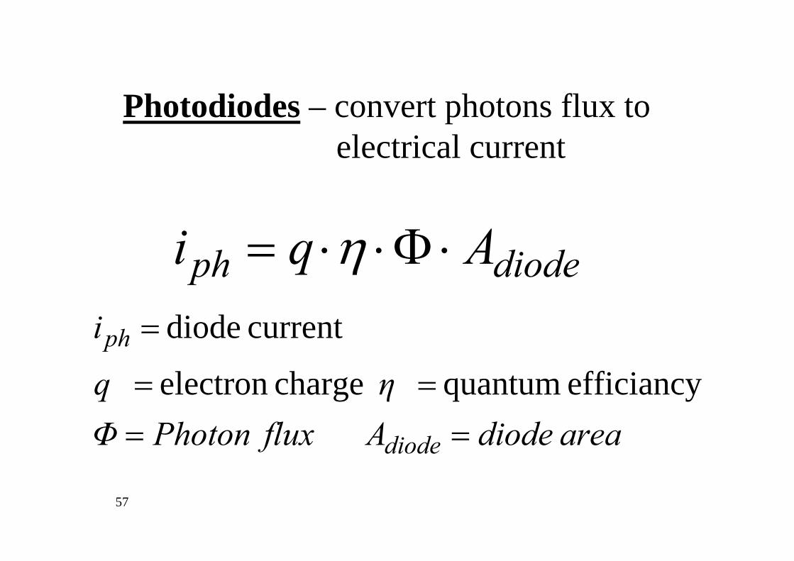
Photodiodes – convert photons flux to electrical current
diodeph Aqi ⋅Φ⋅⋅= η
areadiodeAfluxPhotonΦηq
i
diode
ph
efficiancy quantum chargeelectron
currentdiode
====
=

58
Response to PL biosensor
Bio chip
Cell’s container
Photodiode
Excitation chip (Blue)
Emission (green)

59
PL biosensor-Photodiode Response
diodethetodistance
4Ann 2
diodecellsph,diodeph,
−−
⋅⋅=
rfactorlGeometricaGF
GFrπ
Assume small detector:
60
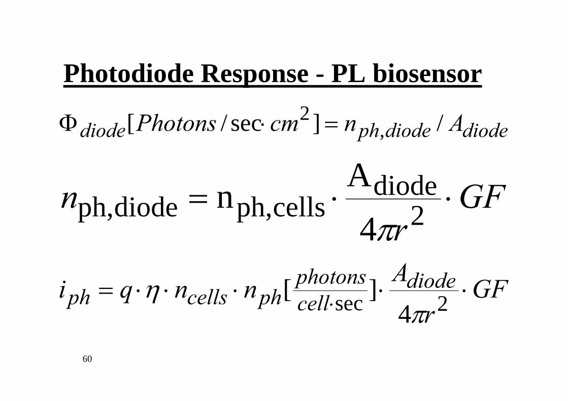
PL biosensor-Photodiode Response
diodediodephdiode AncmPhotons /]sec/[ ,2 =⋅Φ
GFr
n ⋅⋅= 2diode
cellsph,diodeph,4
Anπ
GFr
Annqi diodecellphotons
phcellsph ⋅⋅⋅⋅⋅= ⋅ 2sec 4][
πη

61
PL biosensor-Photodiode Response
cellsph
cellphotons
ph
npowerExcitationi
powerExcitationn
⋅∝
⋅∝⋅
][ sec
Assumptions
• No absorption of PL signal
• Linear PL effect

62
Photodiodes – limits
diode29-
A Amp/cm 10 ×≈
TempRoomleakageiTypical
leakagediodeph iAqi >⋅Φ⋅⋅= η
secphotons/cm 10~ /q][Amp/cm 10 21029- ⋅>Φ η
The limit is on ncellsx Excitation power

63
Photodiodes – limits
Solutions:
Lower temperature
Lower leakage (better process)

64
Avalanche Photodiodes – converts photons flux to electrical current with internal gain
diodeph AqGi ⋅Φ⋅⋅⋅= η
areadiodeAfluxPhotonΦηq
gainernalG
i
diode
ph
efficiancy quantum chargeelectron
int
currentdiode
====
=
=

65
converts photons flux –Photomultipliers to electrical current with high internal gain
Highlights:
Very sensitive
Problems
Slow
Expensive
Very difficult to integrate

66
Michael L. Simpson et al., Sensors and actuators B, 2002, 179-185
Example: integrated photodiode with CMOS circuit
Micro-luminescent detection ASIC:
Chip area: 2mm X2mm
Photodiode area: 1.47 mm2

67
Michael L. Simpsona,b, Gary S. Saylerc, Greg Pattersonb, David E. Nivensc, Eric K. Boltonb, James M. Rochelleb, James C. Arnottb, “An integrated CMOS microluminometer for low-level luminescencesensing in the bioluminescent bioreporter integrated circuit”, Sensors and Actuators B 72 (2001) 134±140
A bioluminescent bioreporter integrated circuit is formed by placing genetically engineered bioluminescent cells on an optically sensitive integrated circuit (IC). The molecular specificity is provided by the cells, while the IC provides the advantages of a microelectronic format.

68Michael L. Simpson et al., Sensors
and actuators B, 2002, 179-185
Bio-luminescence from a growing culture of P. fluorescens 5RL. At t=0 1ppm salycilate was added to induce the lux genes.
Example: integrated photodiode with CMOS circuit

69
Detector arraysHighlights
• Many containers – battery on a chip
• Can be software controlled for the collection area
Problems:
• Electronics area is limited by the biochip
• Complex optical constraints

70

71
• SXGA resolution: 1280 x 1024 pixels
• High sensitivity 20 µV/electron
• High fill factor 60 %
• Quantum efficiency > 50% between 500 and 700 nm.
• 20 noise electrons = 50 noise photons
• Dynamic range: 66 dB (2000:1)
• 7 x 7 µm2 pixels
• Low fixed pattern noise (1 % Vsat p/p)
• Low dark current: 344 pA/cm2 (1055 electrons/s, 1 minute auto saturation)
Special low-noise CMOS imager (IBIS4)

72
Example
Integrated E.Coli whole cell photo-luminescent
detection of acute toxicity in water

73
:System Technology (IMST)-Integrated Micro
Specific technologies:
Integrated fluidic systems for miniature analytical instruments,
Embedded sensors and actuatorsfor activating bio-assays and sensing their response
CCD Imager and Mixed signal VLSI chipfor signal detection, processing, storage
and communication

74
The Bio-chip Technology• Miniature propelling mechanisms
– Internal - nano/micro-litters levels – External – micro-litters levels
• Capable of sequential operations using multi-reagents.
• Capable of parallel operations of different tests• Low-cost mass production disposable chip -
currently we use Si substrate, however, the technology can be applied on plastics.
75
Bio-material on chip
• Photoluminescent bio-sensors• Bio-material was deposited on the chip.• recA::gfp, E. coli• Nalidixic acid induction
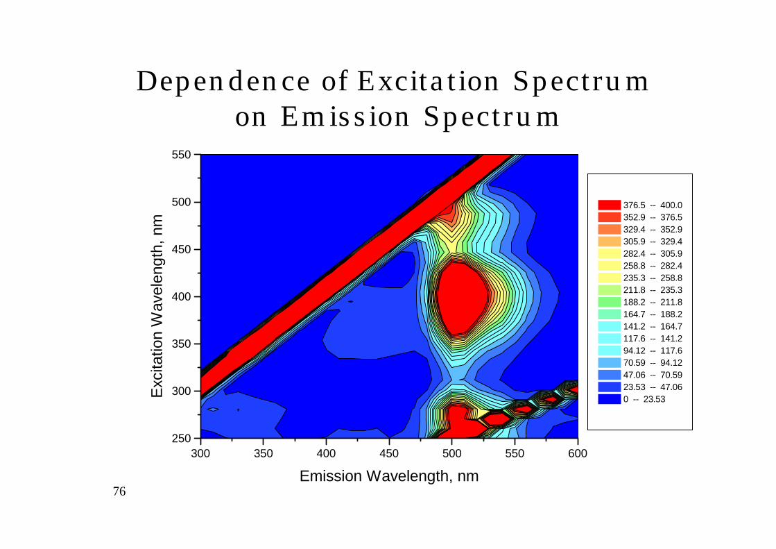
76
300 350 400 450 500 550 600250
300
350
400
450
500
550
376.5 -- 400.0 352.9 -- 376.5 329.4 -- 352.9 305.9 -- 329.4 282.4 -- 305.9 258.8 -- 282.4 235.3 -- 258.8 211.8 -- 235.3 188.2 -- 211.8 164.7 -- 188.2 141.2 -- 164.7 117.6 -- 141.2 94.12 -- 117.6 70.59 -- 94.12 47.06 -- 70.59 23.53 -- 47.06 0 -- 23.53
Emission Wavelength, nm
Exci
tatio
n W
avel
engt
h, n
m
Dependence of Excitation Spectrum on Emission Spectrum
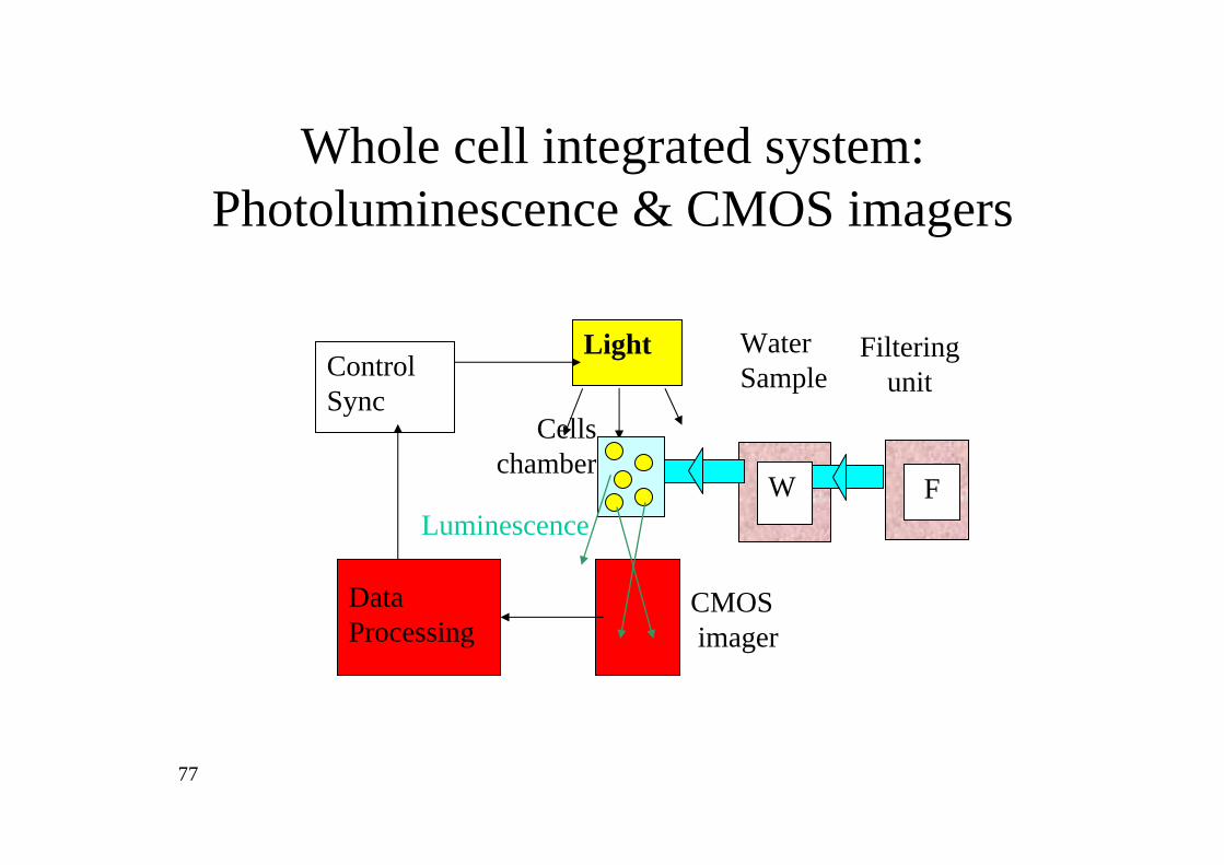
77
Light
W F
Data Processing
CMOSimager
Luminescence
Control Sync
Cells chamber
WaterSample
Filtering unit
Whole cell integrated system: Photoluminescence & CMOS imagers

78
wafer level

79
The MEMS Bio-chip• Contains inspection chambers, micro-pumps, water channels and inlet ports• A 12-well modular design
1 mm

80
Integrated level

81
Illuminator- GaN blue LED array ( ~ 470 nm)
Detector and signal processor- 1 Mpixel CMOS imager
- Signal detection and cell container signal acquisition
- Signal compression and storage

82
Background
Actual chip
Chip design
Toxic sampleNeutral sample
Quantification

83
Typical output data
I
ttrigger
High concentration
Mediumconcentration Low concentration
hours

84
Summary
• Whole cell biosensors require special micro fluidic and sensor design
• Micro-fluidic system requires fluid containers, micro-pipes, micro pumps inlet and outlet.
• We demonstrated open loop system, however closed loop system is possible
• Bio-material deposition is still a problem• Both optical (gfp, lux) and electrical sensing is
possible.,