Embed Size (px)
Citation preview
Wheels and sprockets
www.renold.com
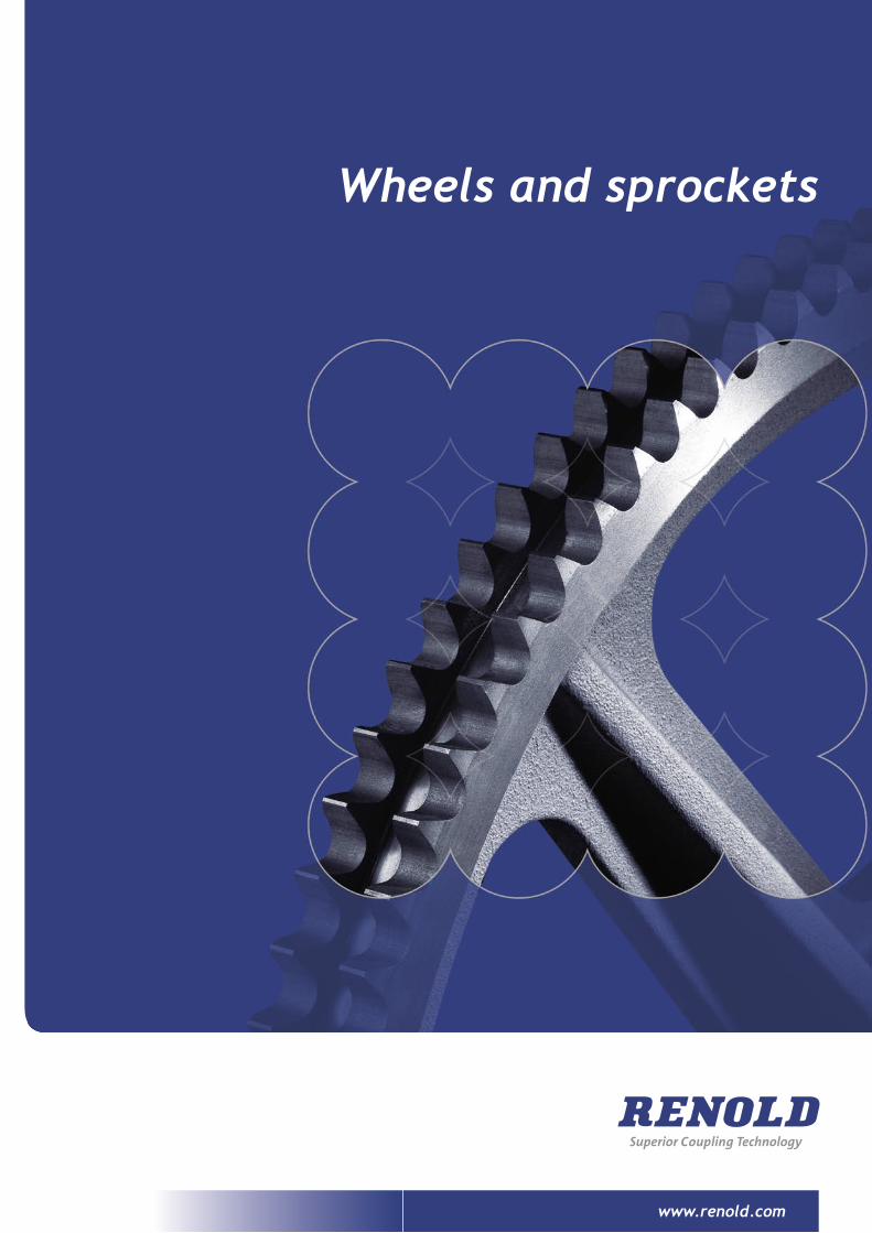
Located in South Wales, Renold Clutches and Couplings’ Cardiff
factory was initially opened in 1946 as a dedicated sprocket
manufacturing facility with operations being moved to a modern
purpose built factory in 1991.
With the company’s reputation for quality a cornerstone of
its success, Renold manufacture standard sprockets as well as
custom wheels of up to 1 metre in size.
In addition to sprockets and wheels, Renold also produce a
wide range of power transmission products ranging from sprag
clutches to fluid couplings, all designed and manufactured to
the highest standards.
The company calls on its vast expertise to create specific
solutions to customers’ unique requirements. International
companies from steel manufacturing to food processing and
from escalators to textile machinery have chosen Renold to
solve their problems.
Background
Staff celebrate the company’s first anniversary in 1947.
Renold Works, Cardiff,1946.
All historical images courtesy of The Renold Collection.
Renold Works factory floor, 1947.
www.renold.com
Page 01
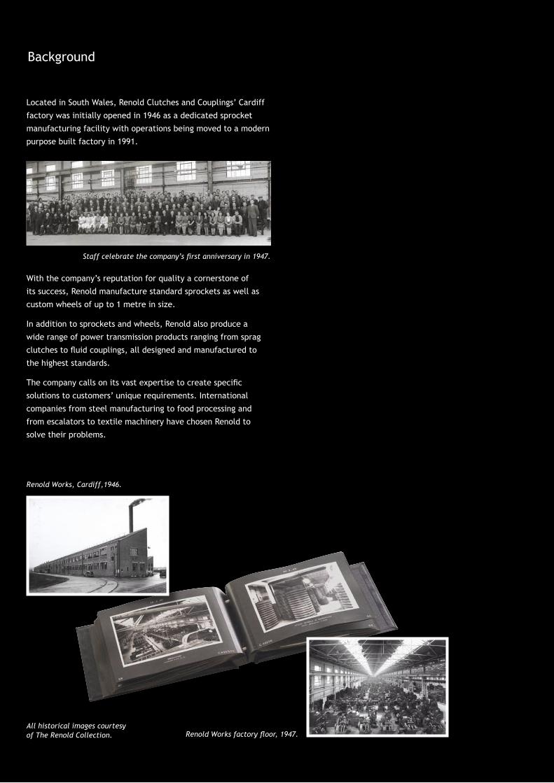
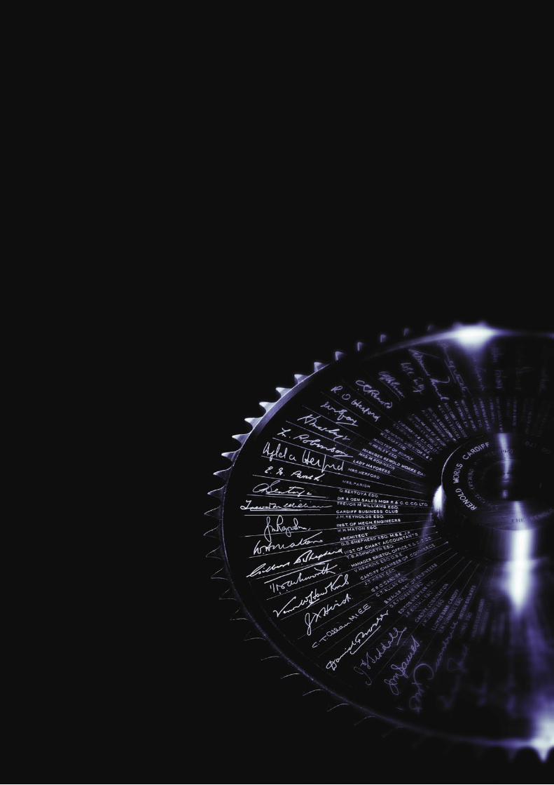
Commemorative wheel engraved with the signatures of dignitaries and guests at the opening of the Renold Cardiff factory in 1946.

Page 02
Contents
Page Designer guide Introduction 04
Sprockets 04
Sprocket dimensions 05
Pitch circle diameter 05
Tooth form 05
Number of teeth 06
Centre distance 07
Lie of drive 07
Centres 08
Angle 08
Rotation 08
Selection of sprocket materials 08
Sprocket and chain compatibility 08
Preparation 09
Checking sprocket alignment 09
Transmission sprockets 9.525mm (0.375") pitch 12
12.7mm (0.500") pitch 14
15.875mm (0.625") pitch 16
19.05mm (0.750") pitch 18
25.4mm (1.000") pitch 20
31.75mm to 38.10mm (0.375" to 1.5") pitch 22
44.45mm to 50.8mm (1.75" to 2.0") pitch 23
Modifications and specials 24
Standard conveyor sprockets 3000 lbf, 13000 Newtons 28
4500 lbf, 20000 Newtons 29
6000 lbf, 27000 Newtons 29
7500 lbf, 33000 Newtons 29
12000 lbf, 54000 Newtons 30
15000 lbf, 67000 Newtons 30
24000 lbf, 107000 Newtons 30
30000 lbf, 134000 Newtons 30
Clutches and coupling product range 32
Wheels and sprockets
Designer guide
Page 03
www.renold.com
�������������� �����������������
Designer guide
Wheels and sprockets
Page 04
[ fig 02 ]
Introduction
Renold manufacture a comprehensive range of stock sprockets
for British Standard chain up to two inch pitch.
Other sizes of sprocket, including those to American Standard
dimensions, are also available on request.
Special sprockets are also manufactured on request, in special
materials or formats, normally to suit a specific application in
harsh or difficult drive situations, examples being:
• Sprockets incorporating shafts
• Welded or detachable hubs
• Shear pin devices fitted
• Necklace sprockets made up of chain plates and individual
tooth sections for turning large drums or tables
• Combination sprockets (two or more sprockets combined
having different pitch sizes and numbers of teeth)
• Sprockets in two or more sections, ie, split sprockets or
segmental sprockets
Sprockets
The normal function of a chain sprocket is not only to drive or
be driven by the chain, but also to guide and support it in its
intended path.
Sprockets manufactured from good quality iron castings are
suitable for the majority of applications. For arduous duty it
may be necessary to use steel sprockets having a 0.4% carbon
content. For extremely arduous duty the tooth flanks should
be flame hardened. There are other materials which may
be specified for particular requirements. Stainless steel for
example is used in high temperature or corrosive conditions.
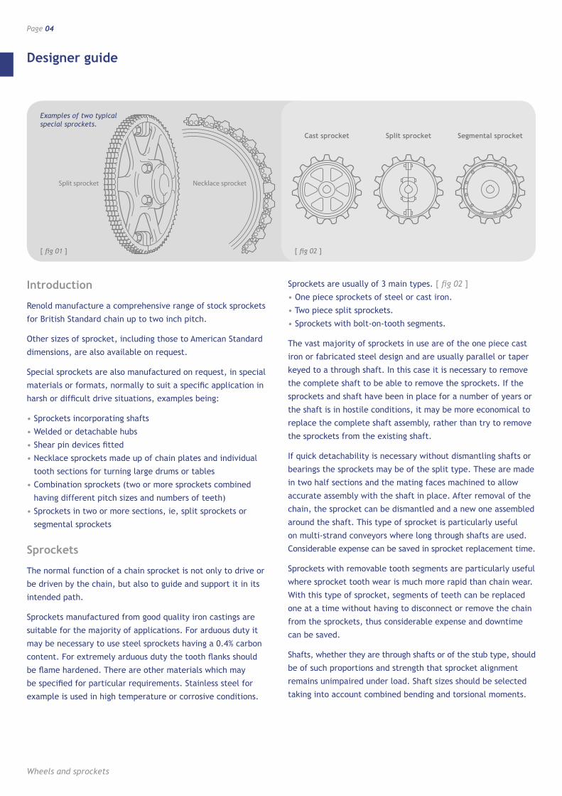
Sprockets are usually of 3 main types. [ fig 02 ]
• One piece sprockets of steel or cast iron.
• Two piece split sprockets.
• Sprockets with bolt-on-tooth segments.
The vast majority of sprockets in use are of the one piece cast
iron or fabricated steel design and are usually parallel or taper
keyed to a through shaft. In this case it is necessary to remove
the complete shaft to be able to remove the sprockets. If the
sprockets and shaft have been in place for a number of years or
the shaft is in hostile conditions, it may be more economical to
replace the complete shaft assembly, rather than try to remove
the sprockets from the existing shaft.
If quick detachability is necessary without dismantling shafts or
bearings the sprockets may be of the split type. These are made
in two half sections and the mating faces machined to allow
accurate assembly with the shaft in place. After removal of the
chain, the sprocket can be dismantled and a new one assembled
around the shaft. This type of sprocket is particularly useful
on multi-strand conveyors where long through shafts are used.
Considerable expense can be saved in sprocket replacement time.
Sprockets with removable tooth segments are particularly useful
where sprocket tooth wear is much more rapid than chain wear.
With this type of sprocket, segments of teeth can be replaced
one at a time without having to disconnect or remove the chain
from the sprockets, thus considerable expense and downtime
can be saved.
Shafts, whether they are through shafts or of the stub type, should
be of such proportions and strength that sprocket alignment
remains unimpaired under load. Shaft sizes should be selected
taking into account combined bending and torsional moments.
Cast sprocket Split sprocket Segmental sprocket
[ fig 01 ]
Examples of two typical special sprockets.
Designer guide
www.renold.com
Page 05
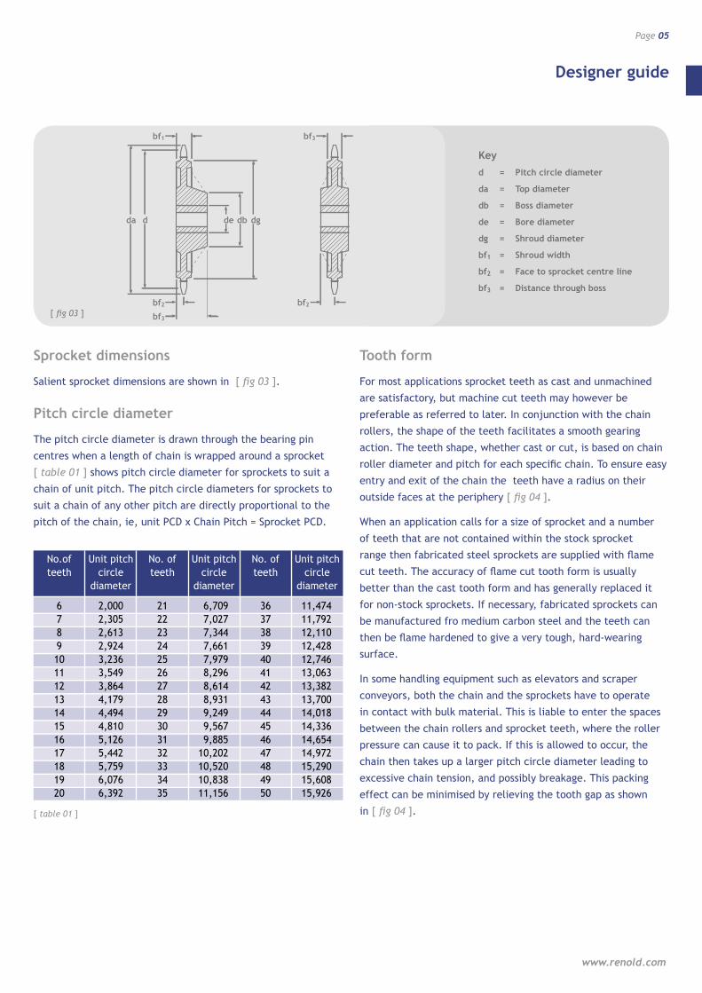
Sprocket dimensions
Salient sprocket dimensions are shown in [ fig 03 ].
Pitch circle diameter
The pitch circle diameter is drawn through the bearing pin
centres when a length of chain is wrapped around a sprocket
[ table 01 ] shows pitch circle diameter for sprockets to suit a
chain of unit pitch. The pitch circle diameters for sprockets to
suit a chain of any other pitch are directly proportional to the
pitch of the chain, ie, unit PCD x Chain Pitch = Sprocket PCD.
Tooth form
For most applications sprocket teeth as cast and unmachined
are satisfactory, but machine cut teeth may however be
preferable as referred to later. In conjunction with the chain
rollers, the shape of the teeth facilitates a smooth gearing
action. The teeth shape, whether cast or cut, is based on chain
roller diameter and pitch for each specific chain. To ensure easy
entry and exit of the chain the teeth have a radius on their
outside faces at the periphery [ fig 04 ].
When an application calls for a size of sprocket and a number
of teeth that are not contained within the stock sprocket
range then fabricated steel sprockets are supplied with flame
cut teeth. The accuracy of flame cut tooth form is usually
better than the cast tooth form and has generally replaced it
for non-stock sprockets. If necessary, fabricated sprockets can
be manufactured fro medium carbon steel and the teeth can
then be flame hardened to give a very tough, hard-wearing
surface.
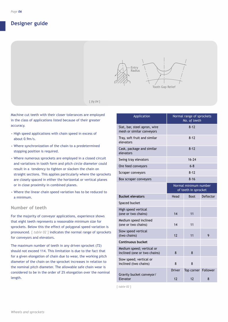
In some handling equipment such as elevators and scraper
conveyors, both the chain and the sprockets have to operate
in contact with bulk material. This is liable to enter the spaces
between the chain rollers and sprocket teeth, where the roller
pressure can cause it to pack. If this is allowed to occur, the
chain then takes up a larger pitch circle diameter leading to
excessive chain tension, and possibly breakage. This packing
effect can be minimised by relieving the tooth gap as shown
in [ fig 04 ]. [ table 01 ]
No.of teeth
6 7 8 9 10 11 12 13 14 15 16 17 18 19 20
Unit pitch circle
diameter
2,000 2,305 2,613 2,924 3,236 3,549 3,864 4,179 4,494 4,810 5,126 5,442 5,759 6,076 6,392
No. of teeth
21 22 23 24 25 26 27 28 29 30 31 32 33 34 35
Unit pitch circle
diameter
6,709 7,027 7,344 7,661 7,979 8,296 8,614 8,931 9,249 9,567 9,885 10,202 10,520 10,838 11,156
No. of teeth
36 37 38 39 40 41 42 43 44 45 46 47 48 49 50
Unit pitch circle
diameter
11,474 11,792 12,110 12,428 12,746 13,063 13,382 13,700 14,018 14,336 14,654 14,972 15,290 15,608 15,926
da d dbde
bf1
bf2
dg
bf3
bf3
bf2[ fig 03 ]
Keyd = Pitch circle diameter
da = Top diameter
db = Boss diameter
de = Bore diameter
dg = Shroud diameter
bf1 = Shroud width
bf2 = Face to sprocket centre line
bf3 = Distance through boss
Designer guide
Wheels and sprockets
Page 06
Machine cut teeth with their closer tolerances are employed
in the class of applications listed because of their greater
accuracy.
• High speed applications with chain speed in excess of
about 0.9m/s.
• Where synchronization of the chain to a predetermined
stopping position is required.
• Where numerous sprockets are employed in a closed circuit
and variations in tooth form and pitch circle diameter could
result in a tendency to tighten or slacken the chain on
straight sections. This applies particularly where the sprockets
are closely spaced in either the horizontal or vertical planes
or in close proximity in combined planes.
• Where the linear chain speed variation has to be reduced to
a minimum.
Number of teeth
For the majority of conveyor applications, experience shows
that eight teeth represents a reasonable minimum size for
sprockets. Below this the effect of polygonal speed variation is
pronounced. [ table 02 ] indicates the normal range of sprockets
for conveyors and elevators.
The maximum number of teeth in any driven sprocket (72)
should not exceed 114. This limitation is due to the fact that
for a given elongation of chain due to wear, the working pitch
diameter of the chain on the sprocket increases in relation to
the nominal pitch diameter. The allowable safe chain wear is
considered to be in the order of 2% elongation over the nominal
length.
Tooth Gap Relief
Entry Radius
[ fig 04 ]
[ table 02 ]
Application
Slat, bar, steel apron, wire mesh or similar conveyors
Tray, soft fruit and similar elevators
Cask, package and similar elevators
Swing tray elevators
Ore feed conveyors
Scraper conveyors
Box scraper conveyors
Normal range of sprockets No. of teeth
8-12
8-12
8-12
16-24
6-8
8-12
8-16
Bucket elevators
Spaced bucket
High speed vertical (one or two chains)
Medium speed inclined (one or two chains)
Slow speed vertical (two chains)
Continuous bucket
Medium speed; vertical or inclined (one or two chains)
Slow speed; vertical or inclined (two chains)
Gravity bucket conveyor/ Elevator
Normal minimum number of teeth in sprocket
Head Boot Deflector
14 11
14 11
12 11 9
8 8
8 8
Driver Top corner Follower 12 12 8
Designer guide
www.renold.com
Page 07
Minimum six teeth
A simple formula for determining how much chain elongation
a sprocket can accommodate is 200 N expressed as a percentage
where N is the number of teeth on the largest sprocket in the
drive system.
It is good practice to have the sum of the teeth not less than 50
where both the driver and driven sprockets are operated by the
same chain, eg, on a 1:1 ratio drive, both sprockets should have
25 teeth each.
Centre distance
For optimum wear life, centre distance between two sprockets
should normally be within the range 30 to 50 times the chain
pitch. On drive proposals with centre distances below 30 pitches
or greater than 2m, we would recommend that the drive details
are discussed with our technical staff.
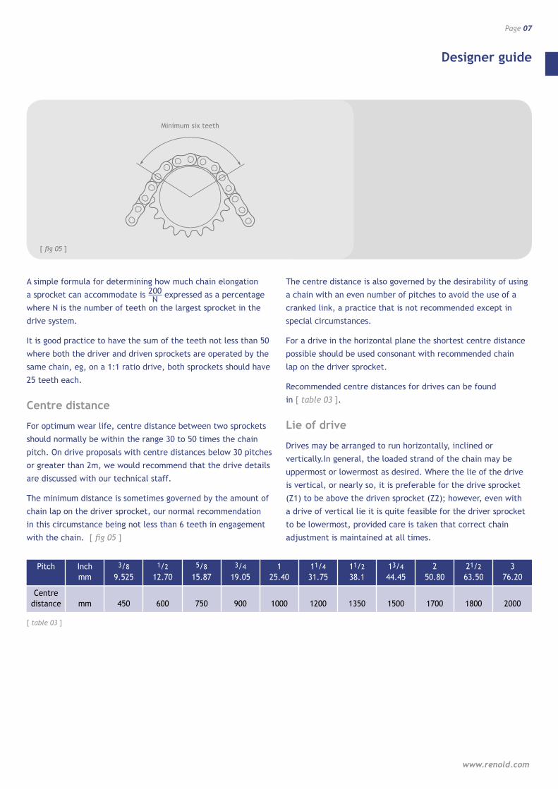
The minimum distance is sometimes governed by the amount of
chain lap on the driver sprocket, our normal recommendation
in this circumstance being not less than 6 teeth in engagement
with the chain. [ fig 05 ]
The centre distance is also governed by the desirability of using
a chain with an even number of pitches to avoid the use of a
cranked link, a practice that is not recommended except in
special circumstances.
For a drive in the horizontal plane the shortest centre distance
possible should be used consonant with recommended chain
lap on the driver sprocket.
Recommended centre distances for drives can be found
in [ table 03 ].
Lie of drive
Drives may be arranged to run horizontally, inclined or
vertically.In general, the loaded strand of the chain may be
uppermost or lowermost as desired. Where the lie of the drive
is vertical, or nearly so, it is preferable for the drive sprocket
(Z1) to be above the driven sprocket (Z2); however, even with
a drive of vertical lie it is quite feasible for the driver sprocket
to be lowermost, provided care is taken that correct chain
adjustment is maintained at all times.
[ fig 05 ]
[ table 03 ]
Pitch
Centre distance
Inch mm
mm
3/8 9.525
450
1/2 12.70
600
5/8 15.87
750
3/4 19.05
900
1 25.40
1000
11/4 31.75
1200
11/2 38.1
1350
13/4 44.45
1500
2 50.80
1700
21/2 63.50
1800
3 76.20
2000

Designer guide
Wheels and sprockets
Page 08
Centres
The centre distance between the axis of the two shafts or
sprockets. [ fig 06 ]
Angle
The lie of the drive is given by the angle formed by the line
through the shaft centres and a horizontal line. [ fig 06 ]
Rotation
Viewed along the axis of the driven shaft the rotation can be
clockwise or anti-clockwise. [ fig 06 ]
Selection of sprocket materials
Choice of material and heat treatment will depend upon shape,
diameter and mass of the sprocket. [ table 04 ] can be used as a
simple guide to the correct selection of sprocket material.
Sprocket and chain compatibility
Most drives have an even number of pitches in the chain and by
using a driver sprocket with an odd number of teeth, uniform
wear distributes over both chain and sprocket teeth is ensured.
Even numbers of teeth for both the driver and driven sprockets
can be used, but wear distribution on both the sprocket teeth
and chain is poor.
[ table 04 ]
Sprocket
Up to 29T
30T and over
Smooth running
EN8 or EN9
Cast iron
Moderate shocks
EN8 or EN9 Hardened and tempered or
case hardened Mild Steel
Mild Steel or Meehanite
Heavy shocks
EN8 or EN9 Hardened and tempered or
case hardened Mild Steel
EN8 or EN9 Hardened and tempered or
case hardened Mild Steel
J
Z1 Z2
c
c
Z2
Z1
[ fig 06 ]
Centres Angle Rotation
Designer guide
www.renold.com
Page 09
Preparation
Check equipment to ensure that general transmission
requirements are correct (eg, flexible couplings, flywheel,
means of drive adjustment).
Check condition and rigidity of the shafts and bearings,
particularly if there has been considerable previous service with
an alternative method of transmission. Replace or rectify if
necessary.
Driver and driven shafts should be checked to ensure they are
level and parallel to each other. This applies equally to the
jockey shaft if present.
Use a spirit level and adjustable comparator bar or micrometer
between shafts at extreme points on each side of the drive.
Rectify any parallelism error present and mark a permanent
datum line for the adjustable shaft.
Place sprockets or respective shafts in approximate alignment
and fit the keys in accordance with correct engineering
practice. Do not finally secure keys at this stage.
Care must be taken with sprockets of split design to ensure
perfect abutting of the faces of each half. Proceed with the key
fitting after the halves are finally bolted together, otherwise
the key can prevent correct assembly and subsequently result
in malgearing.
It should be verified that key heads will not project beyond the
width of any chaincases.
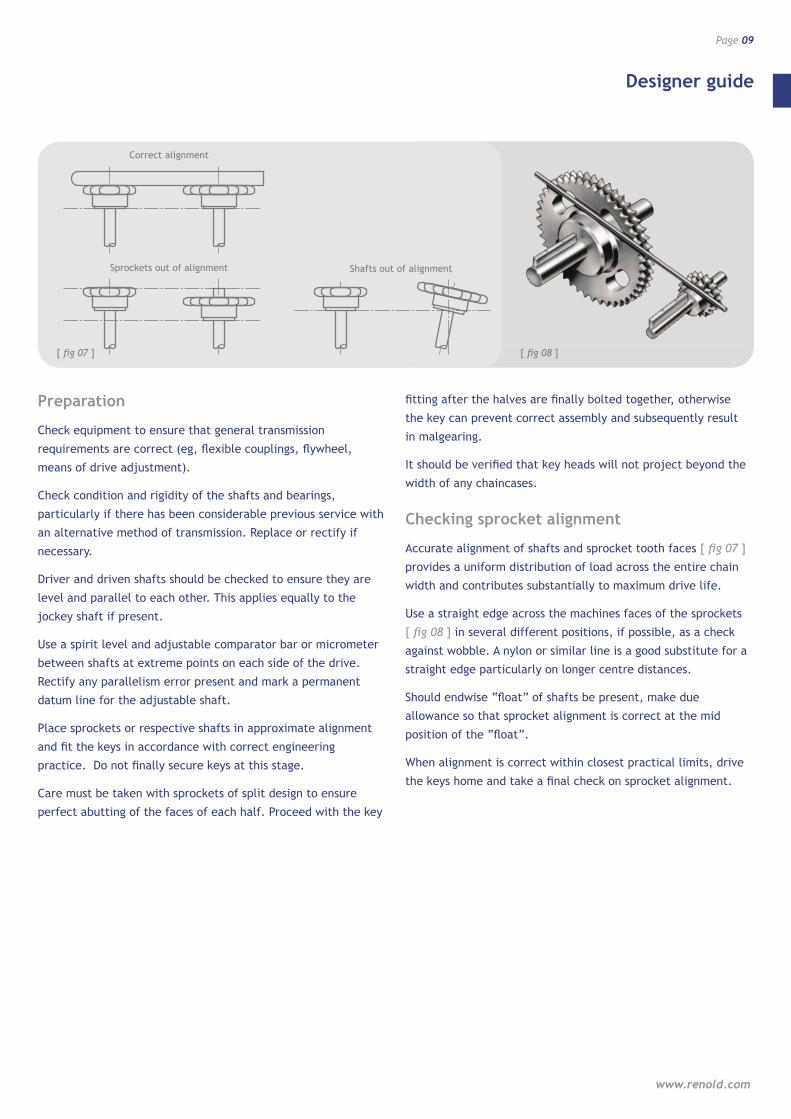
Checking sprocket alignment
Accurate alignment of shafts and sprocket tooth faces [ fig 07 ]
provides a uniform distribution of load across the entire chain
width and contributes substantially to maximum drive life.
Use a straight edge across the machines faces of the sprockets
[ fig 08 ] in several different positions, if possible, as a check
against wobble. A nylon or similar line is a good substitute for a
straight edge particularly on longer centre distances.
Should endwise “float” of shafts be present, make due
allowance so that sprocket alignment is correct at the mid
position of the “float”.
When alignment is correct within closest practical limits, drive
the keys home and take a final check on sprocket alignment.
[ fig 08 ]
Correct alignment
Sprockets out of alignment Shafts out of alignment
[ fig 07 ]

Designer guide Notes
Wheels and sprockets
Page 10

Transmission sprockets
Page 11
www.renold.com
Transmission sprockets ISO 606
Wheels and sprockets
Page 12
B1
ACE
D
F
B1
AC
E
D
F
b1
ACE
D
F
B2
b1
AC
E
D
F
B2
ACE
D
F
b1
B3B2 AC
E
D
F
b1
B3B2
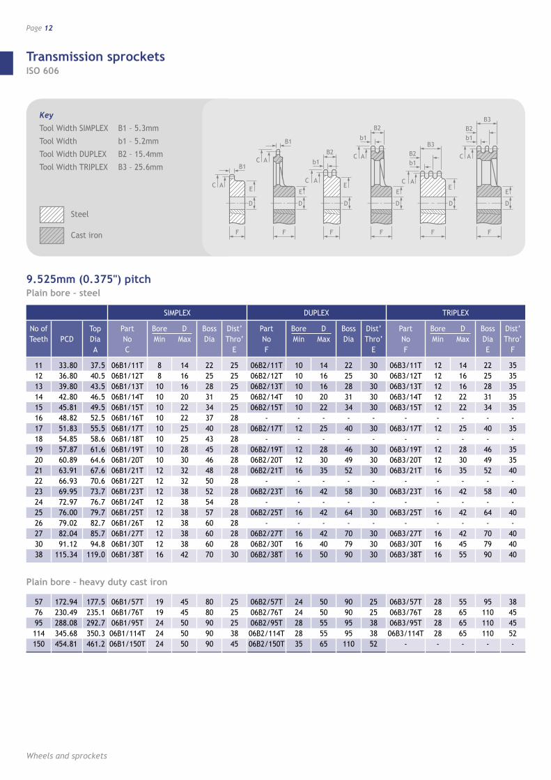
Key
Tool Width SIMPLEX B1 – 5.3mm
Tool Width b1 – 5.2mm
Tool Width DUPLEX B2 – 15.4mm
Tool Width TRIPLEX B3 – 25.6mm
Steel
Cast iron
9.525mm (0.375") pitchPlain bore – steel
No of Teeth
11 12 13 14 15 16 17 18 19 20 21 22 23 24 25 26 27 30 38
PCD
33.80 36.80 39.80 42.80 45.81 48.82 51.83 54.85 57.87 60.89 63.91 66.93 69.95 72.97 76.00 79.02 82.04 91.12 115.34
Top Dia A
37.5 40.5 43.5 46.5 49.5 52.5 55.5 58.6 61.6 64.6 67.6 70.6 73.7 76.7 79.7 82.7 85.7 94.8
119.0
Part No C
06B1/11T 06B1/12T 06B1/13T 06B1/14T 06B1/15T 06B1/16T 06B1/17T 06B1/18T 06B1/19T 06B1/20T 06B1/21T 06B1/22T 06B1/23T 06B1/24T 06B1/25T 06B1/26T 06B1/27T 06B1/30T 06B1/38T
Bore Min
8 8 10 10 10 10 10 10 10 10 12 12 12 12 12 12 12 12 16
D Max
14 16 16 20 22 22 25 25 28 30 32 32 38 38 38 38 38 38 42
Boss Dia
22 25 28 31 34 37 40 43 45 46 48 50 52 54 57 60 60 60 70
Dist’ Thro’
E
25 25 25 25 25 28 28 28 28 28 28 28 28 28 28 28 28 28 30
Part No F
06B2/11T 06B2/12T 06B2/13T 06B2/14T 06B2/15T
- 06B2/17T
- 06B2/19T 06B2/20T 06B2/21T
- 06B2/23T
- 06B2/25T
- 06B2/27T 06B2/30T 06B2/38T
Bore Min
10 10 10 10 10 -
12 -
12 12 16 -
16 -
16 -
16 16 16
D Max
14 16 16 20 22 -
25 -
28 30 35 -
42 -
42 -
42 40 50
Boss Dia
22 25 28 31 34 -
40 -
46 49 52 -
58 -
64 -
70 79 90
Dist’ Thro’
E
30 30 30 30 30 -
30 -
30 30 30 -
30 -
30 -
30 30 30
Part No F
06B3/11T 06B3/12T 06B3/13T 06B3/14T 06B3/15T
- 06B3/17T
- 06B3/19T 06B3/20T 06B3/21T
- 06B3/23T
- 06B3/25T
- 06B3/27T 06B3/30T 06B3/38T
Bore Min
12 12 12 12 12 -
12 -
12 12 16 -
16 -
16 -
16 16 16
D Max
14 16 16 22 22 -
25 -
28 30 35 -
42 -
42 -
42 45 55
Boss Dia E
22 25 28 31 34 -
40 -
46 49 52 -
58 -
64 -
70 79 90
Dist’ Thro’
F
35 35 35 35 35 -
35 -
35 35 40 -
40 -
40 -
40 40 40
SIMPLEX DUPLEX TRIPLEX
Plain bore – heavy duty cast iron
577695114150
172.94 230.49 288.08 345.68 454.81
177.5235.1292.7350.3461.2
06B1/57T06B1/76T06B1/95T06B1/114T06B1/150T
1919242424
4545505050
8080909090
2525253845
06B2/57T06B2/76T06B2/95T06B2/114T06B2/150T
2424282835
5050555565
90909595110
2525383852
06B3/57T06B3/76T06B3/95T06B3/114T
-
28282828-
55656565-
95110110110
-
38454552-
Transmission sprockets ISO 606
www.renold.com
Page 13
B1
ACE
D
F
B1
AC
E
D
F
b1
ACE
D
F
B2
b1
AC
E
D
F
B2
ACE
D
F
b1
B3B2 AC
E
D
F
b1
B3B2
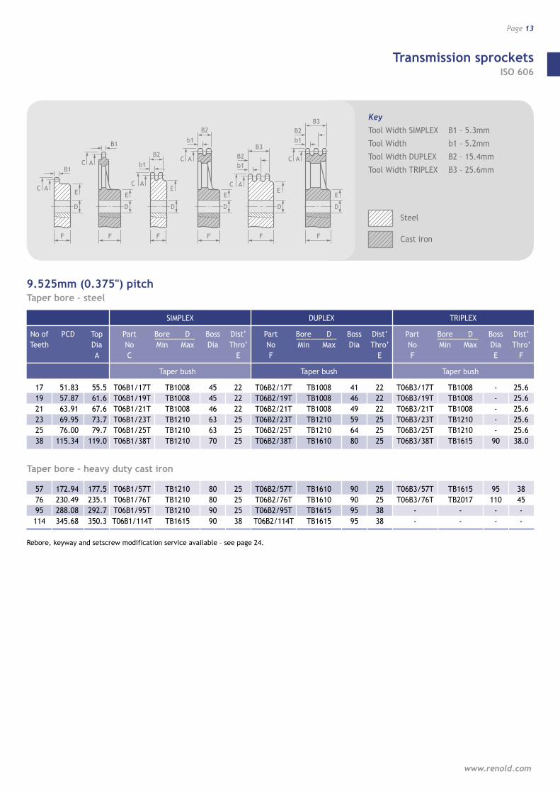
9.525mm (0.375") pitchTaper bore – steel
17 19 21 23 25 38
51.83 57.87 63.91 69.95 76.00 115.34
55.5 61.6 67.6 73.7 79.7
119.0
T06B1/17T T06B1/19T T06B1/21T T06B1/23T T06B1/25T T06B1/38T
Taper bush
TB1008 TB1008 TB1008 TB1210 TB1210 TB1210
45 45 46 63 63 70
22 22 22 25 25 25
T06B2/17T T06B2/19T T06B2/21T T06B2/23T T06B2/25T T06B2/38T
Taper bush
TB1008 TB1008 TB1008 TB1210 TB1210 TB1610
41 46 49 59 64 80
22 22 22 25 25 25
T06B3/17T T06B3/19T T06B3/21T T06B3/23T T06B3/25T T06B3/38T
Taper bush
TB1008 TB1008 TB1008 TB1210 TB1210 TB1615
- - - - -
90
25.6 25.6 25.6 25.6 25.6 38.0
Taper bore – heavy duty cast iron
57 76 95 114
172.94 230.49 288.08 345.68
177.5 235.1 292.7 350.3
T06B1/57T T06B1/76T T06B1/95T T06B1/114T
TB1210 TB1210 TB1210 TB1615
80 80 90 90
25 25 25 38
T06B2/57T T06B2/76T T06B2/95T T06B2/114T
TB1610 TB1610 TB1615 TB1615
90 90 95 95
25 25 38 38
T06B3/57T T06B3/76T
- -
TB1615 TB2017
- -
95 110
- -
38 45 - -
Rebore, keyway and setscrew modification service available – see page 24.
SIMPLEX DUPLEX TRIPLEX
No of Teeth
PCD
Top Dia A
Part No C
Bore Min
D Max
Boss Dia
Dist’ Thro’
E
Part No F
Bore Min
D Max
Boss Dia
Dist’ Thro’
E
Part No F
Bore Min
D Max
Boss Dia E
Dist’ Thro’
F
Key
Tool Width SIMPLEX B1 – 5.3mm
Tool Width b1 – 5.2mm
Tool Width DUPLEX B2 – 15.4mm
Tool Width TRIPLEX B3 – 25.6mm
Steel
Cast iron
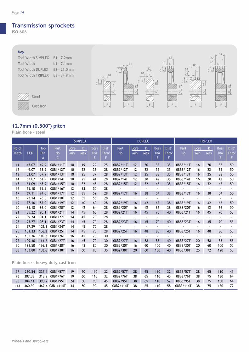
Transmission sprockets ISO 606
Wheels and sprockets
Page 14
B1
ACE
D
F
B1
AC
E
D
F
b1
ACE
D
F
B2
b1
AC
E
D
F
B2
ACE
D
F
b1
B3B2 AC
E
D
F
b1
B3B2
12.7mm (0.500") pitchPlain bore – steel
No of Teeth
11 12 13 14 15 16 17 18 19 20 21 22 23 24 25 26 27 30 38
PCD
45.07 49.07 53.07 57.07 61.09 65.10 69.11 73.14 77.16 81.18 85.22 89.24 93.27 97.29 101.33 105.36 109.40 121.50 153.80
Top Dia A
49.9 53.9 57.9 61.9 65.9 69.9 74.0 78.0 82.0 86.0 90.1 94.1 98.1 102.1 106.2 110.2 114.2 126.3 158.6
Part No C
08B1/11T 08B1/12T 08B1/13T 08B1/14T 08B1/15T 08B1/16T 08B1/17T 08B1/18T 08B1/19T 08B1/20T 08B1/21T 08B1/22T 08B1/23T 08B1/24T 08B1/25T 08B1/26T 08B1/27T 08B1/30T 08B1/38T
Bore Min
10 10 10 10 10 12 12 12 12 12 14 14 14 14 14 16 16 16 16
D Max
19 22 25 25 32 33 35 35 40 42 45 45 45 45 45 45 45 48 60
Boss Dia E
29 33 37 41 45 50 52 56 60 64 68 70 70 70 70 70 70 80 90
Dist’ Thro’
F
25 28 28 28 28 28 28 28 28 28 28 28 28 28 28 30 30 30 35
Part No
08B2/11T 08B2/12T 08B2/13T 08B2/14T 08B2/15T
- 08B2/17T
- 08B2/19T 08B2/20T 08B2/21T
- 08B2/23T
- 08B2/25T
- 08B2/27T 08B2/30T 08B2/38T
Bore Min
12 12 12 12 12 -
16 -
16 16 16 -
16 -
16 -
16 16 20
D Max
20 22 25 28 32 -
38 -
42 42 45 -
45 -
48 -
58 60 60
Boss Dia E
32 35 38 42 46 -
54 -
62 66 70 -
70 -
80 -
85 100 100
Dist’ Thro’
F
35 35 35 35 35 -
38 -
38 38 40 -
40 -
40 -
40 40 40
Part No
08B3/11T 08B3/12T 08B3/13T 08B3/14T 08B3/15T
- 08B3/17T
- 08B3/19T 08B3/20T 08B3/21T
- 08B3/23T
- 08B3/25T
- 08B3/27T 08B3/30T 08B3/38T
Bore Min
16 16 16 16 16 -
16 -
16 16 16 -
16 -
16 -
20 20 25
D Max
20 22 25 28 32 -
38 -
42 42 45 -
45 -
48 -
58 60 72
Boss Dia E
32 35 38 42 46 -
54 -
62 66 70 -
70 -
80 -
85 100 120
Dist’ Thro’
F
50 50 50 50 50 -
50 -
50 50 55 -
55 -
55 -
55 55 55
SIMPLEX DUPLEX TRIPLEX
Plain bore – heavy duty cast iron
577695114
230.54307.33384.11460.90
237.1313.9390.7467.4
08B1/57T08B1/76T08B1/95T08B1/114T
19192434
60605050
1101109090
32324545
08B2/57T08B2/76T08B2/95T08B2/114T
28383838
65656565
110110110110
32455258
08B3/57T08B3/76T08B3/95T08B3/114T
28383838
65757575
110130130130
45646472
Key
Tool Width SIMPLEX B1 – 7.2mm
Tool Width b1 – 7.1mm
Tool Width DUPLEX B2 – 21.0mm
Tool Width TRIPLEX B3 – 34.9mm
Steel
Cast iron

Transmission sprockets ISO 606
www.renold.com
Page 15
B1
ACE
D
F
B1
AC
E
D
F
b1
ACE
D
F
B2
b1
AC
E
D
F
B2
ACE
D
F
b1
B3B2 AC
E
D
F
b1
B3B2
12.7mm (0.500") pitchTaper bore – steel
15 17 19 21 23 25
61.08 69.12 77.16 85.21 93.27 101.33
65.9 74.0 82.0 90.1 98.1
106.2
T08B1/15T T08B1/17T T08B1/19T T08B1/21T T08B1/23T T08B1/25T
Taper bush
TB1008 TB1210 TB1210 TB1610 TB1610 TB1610
45 60 63 71 76 76
22 25 25 25 25 25
T08B2/15T T08B2/17T T08B2/19T T08B2/21T T08B2/23T T08B2/25T
Taper bush
TB1008 TB1210 TB1210 TB1610 TB1610 TB2012
48 56 64 71 79 87
22 25 25 25 25 32
– –
T08B3/19T T08B3/21T T08B3/23T T08B3/25T
Taper bush
- -
TB1215 TB1615 TB1615 TB2017
- -
62 70 70 –
- -
38 38 38
34.9
Taper bore – heavy duty cast iron
38 57 76 95 114
153.79 230.54 307.33 384.11 460.90
158.6 237.1 313.9 390.7 467.4
T08B1/38T T08B1/57T T08B1/76T T08B1/95T T08B1/114T
TB2012 TB2012 TB2012 TB2012 TB2017
90 110 110 110 110
32 32 32 32 32
T08B2/38T T08B2/57T T08B2/76T T08B2/95T T08B2/114T
TB2012 TB2012 TB2012 TB2012 TB2517
100 110 110 110 125
32 32 32 32 45
T08B3/38T T08B3/57T T08B3/76T
- -
TB2017 TB2017 TB2525
- -
– 110 130
- -
34.9 45 64 - –
Rebore, keyway and setscrew modification service available – see page 24.
SIMPLEX DUPLEX TRIPLEX
No of Teeth
PCD
Top Dia A
Part No C
Bore Min
D Max
Boss Dia E
Dist’ Thro’
F
Part No
Bore Min
D Max
Boss Dia E
Dist’ Thro’
F
Part No
Bore Min
D Max
Boss Dia E
Dist’ Thro’
F
Key
Tool Width SIMPLEX B1 – 7.2mm
Tool Width b1 – 7.1mm
Tool Width DUPLEX B2 – 21.0mm
Tool Width TRIPLEX B3 – 34.9mm
Steel
Cast iron
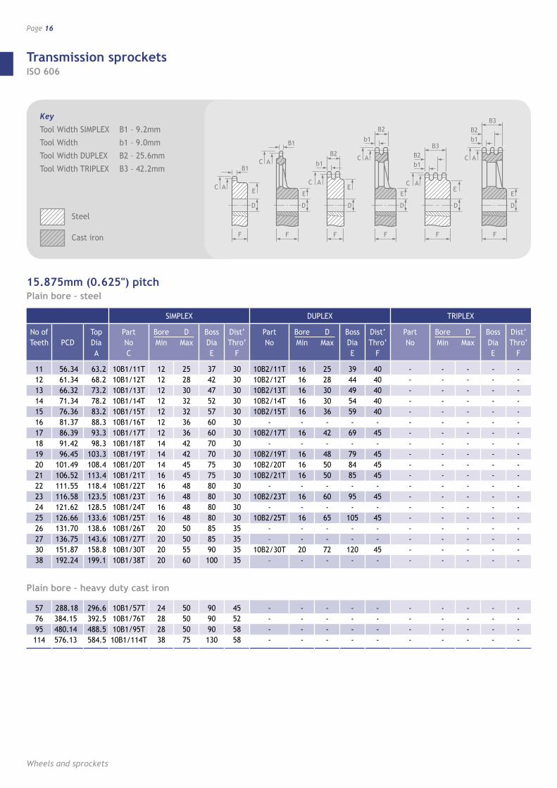
Transmission sprockets ISO 606
Wheels and sprockets
Page 16
B1
ACE
D
F
B1
AC
E
D
F
b1
ACE
D
F
B2
b1
AC
E
D
F
B2
ACE
D
F
b1
B3B2 AC
E
D
F
b1
B3B2
15.875mm (0.625") pitchPlain bore – steel
No of Teeth
11 12 13 14 15 16 17 18 19 20 21 22 23 24 25 26 27 30 38
PCD
56.34 61.34 66.32 71.34 76.36 81.37 86.39 91.42 96.45 101.49 106.52 111.55 116.58 121.62 126.66 131.70 136.75 151.87 192.24
Top Dia A
63.2 68.2 73.2 78.2 83.2 88.3 93.3 98.3
103.3 108.4 113.4 118.4 123.5 128.5 133.6 138.6 143.6 158.8 199.1
Part No C
10B1/11T 10B1/12T 10B1/13T 10B1/14T 10B1/15T 10B1/16T 10B1/17T 10B1/18T 10B1/19T 10B1/20T 10B1/21T 10B1/22T 10B1/23T 10B1/24T 10B1/25T 10B1/26T 10B1/27T 10B1/30T 10B1/38T
Bore Min
12 12 12 12 12 12 12 14 14 14 16 16 16 16 16 20 20 20 20
D Max
25 28 30 32 32 36 36 42 42 45 45 48 48 48 48 50 50 55 60
Boss Dia E
37 42 47 52 57 60 60 70 70 75 75 80 80 80 80 85 85 90 100
Dist’ Thro’
F
30 30 30 30 30 30 30 30 30 30 30 30 30 30 30 35 35 35 35
Part No
10B2/11T 10B2/12T 10B2/13T 10B2/14T 10B2/15T
- 10B2/17T
- 10B2/19T 10B2/20T 10B2/21T
- 10B2/23T
- 10B2/25T
- –
10B2/30T –
Bore Min
16 16 16 16 16 -
16 -
16 16 16 -
16 -
16 - -
20 -
D Max
25 28 30 30 36 -
42 -
48 50 50 -
60 -
65 - -
72 -
Boss Dia E
39 44 49 54 59 -
69 -
79 84 85 -
95 -
105 - -
120 -
Dist’ Thro’
F
40 40 40 40 40 -
45 -
45 45 45 -
45 -
45 - -
45 -
Part No
- - - - - - - - - - - - - - - - - - -
Bore Min
- - - - - - - - - - - - - - - - - - -
D Max
- - - - - - - - - - - - - - - - - - -
Boss Dia E
- - - - - - - - - - - - - - - - - - -
Dist’ Thro’
F
- - - - - - - - - - - - - - - - - - -
SIMPLEX DUPLEX TRIPLEX
Plain bore – heavy duty cast iron
577695114
288.18384.15480.14576.13
296.6392.5488.5584.5
10B1/57T10B1/76T10B1/95T10B1/114T
2428 28 38
50505075
909090130
45525858
- - - -
- - - -
- - - -
- - - -
- - - -
- - - -
- - - -
- - - -
- - - -
- - - -
Key
Tool Width SIMPLEX B1 – 9.2mm
Tool Width b1 – 9.0mm
Tool Width DUPLEX B2 – 25.6mm
Tool Width TRIPLEX B3 – 42.2mm
Steel
Cast iron

Transmission sprockets ISO 606
www.renold.com
Page 17
B1
ACE
D
F
B1
AC
E
D
F
b1
ACE
D
F
B2
b1
AC
E
D
F
B2
ACE
D
F
b1
B3B2 AC
E
D
F
b1
B3B2
15.875mm (0.625") pitchTaper bore – steel
15 17 19 21 23 25
76.36 84.40 96.45 106.51 116.59 126.66
83.2 93.3
103.3 113.4 123.5 133.6
T10B1/15T T10B1/17T T10B1/19T T10B1/21T T10B1/23T T10B1/25T
Taper bush
TB1210 TB1610 TB1610 TB1610 TB1610 TB2012
60 71 75 76 76 90
25 25 25 25 25 32
- - - - - –
Taper bush
- - - - - –
- - - - - –
- - - - - –
- - - - - –
Taper bush
- - - - - –
- - - - - –
- - - - - –
Taper bore – heavy duty cast iron
38 57 76 95
151.87 288.18 384.15 480.14
158.8 296.6 392.5 488.5
T10B1/38T T10B1/57T T10B1/76T T10B1/95T
TB2012 TB2012 TB2012 TB2012
90 110 115 115
32 32 32 45
- - - –
- - - –
- - - –
- - - –
- - - –
- - - –
- - - –
- - - –
Rebore, keyway and setscrew modification service available – see page 24.
SIMPLEX DUPLEX TRIPLEX
No of Teeth
PCD
Top Dia A
Part No C
Bore Min
D Max
Boss Dia E
Dist’ Thro’
F
Part No
Bore Min
D Max
Boss Dia E
Dist’ Thro’
F
Part No
Bore Min
D Max
Boss Dia E
Dist’ Thro’
F
Key
Tool Width SIMPLEX B1 – 9.2mm
Tool Width b1 – 9.0mm
Tool Width DUPLEX B2 – 25.6mm
Tool Width TRIPLEX B3 – 42.2mm
Steel
Cast iron

Transmission sprockets ISO 606
Wheels and sprockets
Page 18
B1
ACE
D
F
B1
AC
E
D
F
b1
ACE
D
F
B2
b1
AC
E
D
F
B2
ACE
D
F
b1
B3B2 AC
E
D
F
b1
B3B2
19.05mm (0.750") pitchPlain bore – steel
No of Teeth
11 12 13 14 15 16 17 18 19 20 21 22 23 24 25 26 27 30 38
PCD
67.62 73.60 79.59 85.61 91.63 97.65 103.67 109.71 115.74 121.78 127.82 133.86 139.90 145.94 152.00 158.04 164.09 182.25 230.69
Top Dia A
75.8 81.8 87.8 93.8 99.9
105.8 111.9 117.9 123.9 130.0 136.1 142.1 148.1 154.1 160.2 166.2 172.3 190.4 238.9
Part No C
12B1/11T 12B1/12T 12B1/13T 12B1/14T 12B1/15T 12B1/16T 12B1/17T 12B1/18T 12B1/19T 12B1/20T 12B1/21T 12B1/22T 12B1/23T 12B1/24T 12B1/25T 12B1/26T 12B1/27T 12B1/30T 12B1/38T
Bore Min
16 16 16 16 16 16 16 16 16 16 20 20 20 20 20 20 20 20 25
D Max
30 32 38 42 48 50 53 53 53 53 55 55 55 55 55 55 55 55 60
Boss Dia E
46 52 58 64 70 75 80 80 80 80 90 90 90 90 90 95 95 95 100
Dist’ Thro’
F
35 35 35 35 35 35 35 35 35 35 40 40 40 40 40 40 40 40 40
Part No
12B2/11T 12B2/12T 12B2/13T 12B2/14T 12B2/15T
- 12B2/17T
- 12B2/19T 12B2/20T 12B2/21T
- 12B2/23T
- 12B2/25T
- 12B2/27T 12B2/30T 12B2/38T*
Bore Min
16 16 16 20 20 -
20 -
20 20 20 -
20 -
20 -
20 20 25
D Max
30 32 38 42 48 -
50 -
55 60 60 -
66 -
72 -
72 72 72
Boss Dia E
47 53 59 65 71 -
83 -
95 100 100
- 110
- 120
- 120 120 120
Dist’ Thro’
F
50 50 50 50 50 -
50 -
50 50 50 -
50 -
50 -
50 50 50
Part No
123B/11T 123B/12T 123B/13T 123B/14T 123B/15T
- 123B/17T
- 123B/19T 123B/20T 123B/21T
- 123B/23T
- 123B/25T
- 123B/27T 123B/30T 123B/38T*
Bore Min
20 20 20 20 20 -
20 -
20 20 25 -
25 -
25 -
25 25 25
D Max
30 32 38 42 48 -
50 -
55 60 60 -
66 -
72 -
72 72 78
Boss Dia E
47 53 59 65 71 -
83 -
95 100 100
- 110
- 120
- 120 120 130
Dist’ Thro’
F
70 70 70 70 70 -
70 -
70 70 70 -
70 -
70 -
70 70 70
SIMPLEX DUPLEX TRIPLEX
Plain bore – heavy duty cast iron
577695114
345.81460.98576.17691.36
355.9471.1586.2701.4
12B1/57T12B1/76T12B1/95T12B1/114T
28353838
55556575
110110110130
52586464
12B2/57T12B2/76T12B2/95T12B2/114T
38485555
659090100
115155155170
64767688
12B3/57T12B3/76T12B3/95T12B3/114T
48553848
9090100100
160165172178
76767676
Key
Tool Width SIMPLEX B1 – 11.1mm
Tool Width b1 – 10.9mm
Tool Width DUPLEX B2 – 30.4mm
Tool Width TRIPLEX B3 – 49.8mm
• Welded hub
Steel
Cast iron
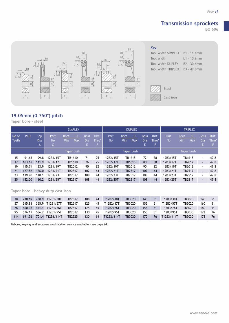
Transmission sprockets ISO 606
www.renold.com
Page 19
B1
ACE
D
F
B1
AC
E
D
F
b1
ACE
D
F
B2
b1
AC
E
D
F
B2
ACE
D
F
b1
B3B2 AC
E
D
F
b1
B3B2
19.05mm (0.750") pitchTaper bore – steel
15 17 19 21 23 25
91.63 103.67 115.74 127.82 139.90 152.00
99.8 111.9 123.9 136.0 148.1 160.2
12B1/15T 12B1/17T 12B1/19T 12B1/21T 12B1/23T 12B1/25T
Taper bush
TB1610 TB1610 TB2012 TB2517 TB2517 TB2517
71 76 90 102 108 108
25 25 32 44 44 44
12B2/15T 12B2/17T 12B2/19T 12B2/21T 12B2/23T 12B2/25T
Taper bush
TB1615 TB1615 TB2012 TB2517 TB2517 TB2517
72 80 90 107 108 108
38 38 32 44 44 44
12B3/15T 12B3/17T 12B3/19T 12B3/21T 12B3/23T 12B3/25T
Taper bush
TB1615 TB2012 TB2012 TB2517 TB2517 TB2517
- - - - - –
49.8 49.8 49.8 49.8 49.8 49.8
Taper bore – heavy duty cast iron
38 57 76 95 114
230.69 345.81 460.98 576.17 691.36
238.9 355.9 471.1 586.2 701.4
T12B1/38T T12B1/57T T12B1/76T T12B1/95T T12B1/114T
TB2517 TB2517 TB2517 TB2517 TB2525
108 125 125 130 130
44 45 45 45 64
T12B2/38T T12B2/57T T12B2/76T T12B2/95T T12B2/114T
TB3020 TB3020 TB3020 TB3020 TB3030
140 155 155 155 170
51 51 51 51 76
T12B3/38T T12B3/57T T12B3/76T T12B3/95T T12B3/114T
TB3020 TB3020 TB3020 TB3030 TB3030
140 160 160 172 178
51 51 51 76 76
Rebore, keyway and setscrew modification service available – see page 24.
SIMPLEX DUPLEX TRIPLEX
No of Teeth
PCD
Top Dia A
Part No C
Bore Min
D Max
Boss Dia E
Dist’ Thro’
F
Part No
Bore Min
D Max
Boss Dia E
Dist’ Thro’
F
Part No
Bore Min
D Max
Boss Dia E
Dist’ Thro’
F
Key
Tool Width SIMPLEX B1 – 11.1mm
Tool Width b1 – 10.9mm
Tool Width DUPLEX B2 – 30.4mm
Tool Width TRIPLEX B3 – 49.8mm
Steel
Cast iron

Transmission sprockets ISO 606
Wheels and sprockets
Page 20
B1
ACE
D
F
B1
AC
E
D
F
b1
ACE
D
F
B2
b1
AC
E
D
F
B2
ACE
D
F
b1
B3B2 AC
E
D
F
b1
B3B2
25.4mm (1.000") pitchPlain bore – steel
No of Teeth
11 12 13 14 15 16 17 18 19 20 21 22 23 24 25 26 27 30 38
PCD
90.14 98.14 106.12 114.15 122.17 130.20 138.22 146.28 154.33 162.38 170.43 178.48 186.53 194.59 202.66 210.72 218.79 243.00 307.59
Top Dia A
101.7 109.7 117.7 125.7 133.7 141.8 149.8 157.8 165.9 173.9 182.0 190.1 198.1 206.2 214.2 222.3 230.4 254.6 319.2
Part No C
16B1/11T 16B1/12T 16B1/13T 16B1/14T 16B1/15T 16B1/16T 16B1/17T 16B1/18T 16B1/19T 16B1/20T 16B1/21T 16B1/22T 16B1/23T 16B1/24T 16B1/25T 16B1/26T 16B1/27T 16B1/30T 16B1/38T*
Bore Min
16 16 16 16 16 20 20 20 20 20 20 20 20 20 20 20 20 20 25
D Max
40 45 50 55 60 60 60 60 60 60 70 70 70 70 70 75 75 75 75
Boss Dia E
61 69 78 84 92 100 100 100 100 100 110 110 110 110 110 120 120 120 120
Dist’ Thro’
F
40 40 40 40 40 45 45 45 45 45 50 50 50 50 50 50 50 50 50
Part No
16B2/11T 16B2/12T 16B2/13T 16B2/14T 16B2/15T
- 16B2/17T
- 16B2/19T 16B2/20T 16B2/21T
- 16B2/23T*
- 16B2/25T*
- 16B2/27T* 16B2/30T* 16B2/38T*
Bore Min
20 20 20 20 20 -
25 -
25 25 25 -
25 -
25 -
25 25 25
D Max
44 45 50 55 60 -
72 -
82 85 85 -
85 -
85 -
85 85 90
Boss Dia E
64 72 80 88 96 -
112 -
128 130 130
- 130
- 130
- 130 130 140
Dist’ Thro’
F
70 70 70 70 70 -
70 -
70 70 70 -
70 -
70 -
70 70 70
Part No
16B3/11T 16B3/12T 16B3/13T 16B3/14T 16B3/15T
- 16B3/17T
- 16B3/19T 16B3/20T 16B3/21T*
- 16B3/23T*
- 16B3/25T*
- 16B3/27T* 16B3/30T* 16B3/38T*
Bore Min
25 25 25 25 25 -
25 -
25 25 25 -
25 -
25
30 30 30
D Max
44 45 50 55 60 -
72 -
82 85 85 -
85 -
85 -
85 85 90
Boss Dia E
64 72 80 88 96 -
112 -
128 130 130
- 130
- 130
- 130 130 140
Dist’ Thro’
F
100 100 100 100 100
- 100
- 100 100 100
- 100
- 100
- 100 100 100
SIMPLEX DUPLEX TRIPLEX
Plain bore – heavy duty cast iron
577695114
461.08614.64768.22921.82
474.9628.4782.0935.6
16B1/57T16B1/76T16B1/95T16B1/114T
35354838
757575100
130135135172
76769098
16B2/57T16B2/76T16B2/95T16B2/114T
38484848
100100110110
178178216203
8989102114
16B3/57T16B3/76T16B3/95T16B3/114T
48555555
110110110125
216216216222
102102102127
Key
Tool Width SIMPLEX B1 – 16.2mm
Tool Width b1 – 15.8mm
Tool Width DUPLEX B2 – 47.7mm
Tool Width TRIPLEX B3 – 79.6mm
• Welded hub
Steel
Cast iron
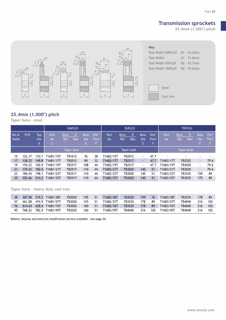
Transmission sprockets 25.4mm (1.000") pitch
www.renold.com
Page 21
B1
ACE
D
F
B1
AC
E
D
F
b1
ACE
D
F
B2
b1
AC
E
D
F
B2
ACE
D
F
b1
B3B2 AC
E
D
F
b1
B3B2
25.4mm (1.000") pitchTaper bore – steel
15 17 19 21 23 25
122.17 138.23 154.32 170.42 186.54 202.66
133.7 149.8 165.9 182.0 198.1 214.2
T16B1/15T T16B1/17T T16B1/19T T16B1/21T T16B1/23T T16B1/25T
Taper bush
TB1615 TB2012 TB2517 TB2517 TB2517 TB2517
76 90 108 110 110 110
38 32 44 44 44 44
T16B2/15T T16B2/17T T16B2/19T T16B2/21T T16B2/23T T16B2/25T
Taper bush
TB2012 TB2517 TB2517 TB3020 TB3020 TB3020
- - -
140 140 140
47.7 47.7 47.7 51 51 51
– T16B3/17T T16B3/19T T16B3/21T T16B3/23T T16B3/25T
Taper bush
- TB2525 TB3030 TB3030 TB3535 TB3535
- - - -
159 175
- 79.6 79.6 79.6 89 89
Taper bore – heavy duty cast iron
38 57 76 95
307.58 461.08 614.64 768.22
319.2 474.9 628.4 782.0
T16B1/38T T16B1/57T T16B1/76T T16B1/95T
TB3020 TB3020 TB3020 TB3020
155 155 160 160
51 51 51 51
T16B2/38T T16B2/57T T16B2/76T T16B2/95T
TB3030 TB3535 TB3535 TB4040
159 178 178 216
76 89 89 102
T16B3/38T T16B3/57T T16B3/76T T16B3/95T
TB3535 TB4040 TB4040 TB4040
178 216 216 216
89 102 102 102
Rebore, keyway and setscrew modification service available – see page 24.
SIMPLEX DUPLEX TRIPLEX
No of Teeth
PCD
Top Dia A
Part No C
Bore Min
D Max
Boss Dia E
Dist’ Thro’
F
Part No
Bore Min
D Max
Boss Dia E
Dist’ Thro’
F
Part No
Bore Min
D Max
Boss Dia E
Dist’ Thro’
F
Key
Tool Width SIMPLEX B1 – 16.2mm
Tool Width b1 – 15.8mm
Tool Width DUPLEX B2 – 47.7mm
Tool Width TRIPLEX B3 – 79.6mm
Steel
Cast iron

Transmission sprockets ISO 606
Wheels and sprockets
Page 22
B1
ACE
D
F
B1
AC
E
D
F
b1
ACE
D
F
B2
b1
AC
E
D
F
B2
ACE
D
F
b1
B3B2 AC
E
D
F
b1
B3B2
Key Sprocket Size 1.25"p 1.5"pitchTool Width SIMPLEX B1 – 18.5 24.1mm
Tool Width b1 – 18.2 23.6mm
Tool Width DUPLEX B2 – 54.6 72.0mm
Tool Width TRIPLEX B3 – 91.0 120.3mm
Steel
Cast iron
31.75mm to 38.10mm (1.25" to 1.5") pitch1.25" plain bore – steel
No of Teeth
17 19 21 23 25
PCD
172.80 192.89 213.03 233.17 253.31
Top Dia A
190.75 210.26 232.41 252.22 272.03
Part No C
20B1/17T 20B1/19T 20B1/21T 20B1/23T 20B1/25T
Bore Min
25 25 30 30 30
D Max
85 85 100 100 100
Boss Dia E
120 120 140 140 140
Dist’ Thro’
F
50 50 55 55 55
Part No
20B2/17T 20B2/19T 20B2/21T 20B2/23T 20B2/25T
Bore Min
30 30 30 30 30
D Max
85 85 100 100 100
Boss Dia E
120 120 140 140 140
Dist’ Thro’
F
80 80 80 80 80
Part No
20B3/17T 20B3/19T 20B3/21T 20B3/23T 20B3/25T
Bore Min
30 30 30 30 30
D Max
85 85 100 100 100
Boss Dia E
120 120 140 140 140
Dist’ Thro’
F
115 115 115 115 115
SIMPLEX DUPLEX TRIPLEX
1.25" plain bore – heavy duty cast iron
38 57 76
384.48576.35768.30
402.08593.34784.86
20B1/38T20B1/57T20B1/76T
304855
10595100
150170178
558189
20B2/38T20B2/57T20B2/76T
306570
105110125
150206224
80127140
20B3/38T20B3/57T20B3/76T
307085
105125140
150 222 254
115147163
1.5" plain bore – steel
1719212325
207.34231.47255.63279.81303.99
225.55248.67276.61300.23324.10
24B1/17T24B1/19T24B1/21T24B1/23T24B1/25T
2525303030
9595105105105
136136150150150
5555606060
24B2/17T24B2/19T24B2/21T24B2/23T24B2/25T
3030303030
9595114114114
136160160160160
100100100100100
24B3/17T24B3/19T24B3/21T24B3/23T24B3/25T
3030404040
95114114114114
136160160160160
150150150150150
1.5" plain bore – heavy duty cast iron
38 57 76
461.37691.62921.97
479.81708.91938.78
24B1/38T24B1/57T24B1/76T
306065
105110125
150196216
60122135
24B2/38T24B2/57T24B2/76T
408085
114140150
160254267
100152168
24B3/38T24B3/57T24B3/76T
4090100
114150170
160267297
150175193
Rebore, keyway and setscrew modification service available – see page 24.
Transmission sprockets ISO 606
www.renold.com
Page 23
B1
ACE
D
F
B1
AC
E
D
F
b1
ACE
D
F
B2
b1
AC
E
D
F
B2
ACE
D
F
b1
B3B2 AC
E
D
F
b1
B3B2
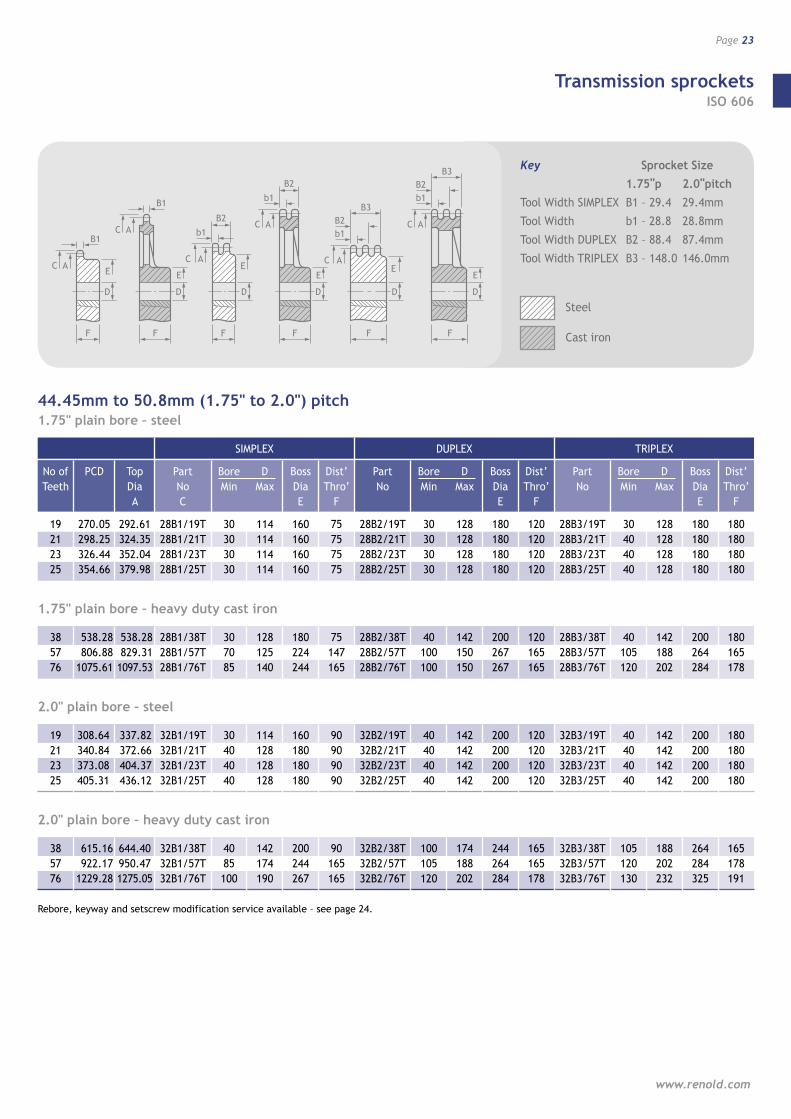
44.45mm to 50.8mm (1.75" to 2.0") pitch1.75" plain bore – steel
No of Teeth
19 21 23 25
PCD
270.05 298.25 326.44 354.66
Top Dia A
292.61 324.35 352.04 379.98
Part No C
28B1/19T 28B1/21T 28B1/23T 28B1/25T
Bore Min
30 30 30 30
D Max
114 114 114 114
Boss Dia E
160 160 160 160
Dist’ Thro’
F
75 75 75 75
Part No
28B2/19T 28B2/21T 28B2/23T 28B2/25T
Bore Min
30 30 30 30
D Max
128 128 128 128
Boss Dia E
180 180 180 180
Dist’ Thro’
F
120 120 120 120
Part No
28B3/19T 28B3/21T 28B3/23T 28B3/25T
Bore Min
30 40 40 40
D Max
128 128 128 128
Boss Dia E
180 180 180 180
Dist’ Thro’
F
180 180 180 180
SIMPLEX DUPLEX TRIPLEX
1.75" plain bore – heavy duty cast iron
38 57 76
538.28806.88
1075.61
538.28829.31
1097.53
28B1/38T28B1/57T28B1/76T
307085
128125140
180224244
75147165
28B2/38T28B2/57T28B2/76T
40100100
142150150
200267267
120165165
28B3/38T28B3/57T28B3/76T
40105120
142188202
200 264 284
180165178
2.0" plain bore – steel
19212325
308.64340.84373.08405.31
337.82372.66404.37436.12
32B1/19T32B1/21T32B1/23T32B1/25T
304040 40
114128128128
160180180 180
909090 90
32B2/19T32B2/21T32B2/23T32B2/25T
40404040
142142142142
200 200 200 200
120120120120
32B3/19T32B3/21T32B3/23T32B3/25T
40404040
142142142142
200200200200
180180180180
2.0" plain bore – heavy duty cast iron
38 57 76
615.16922.17
1229.28
644.40950.471275.05
32B1/38T32B1/57T32B1/76T
4085100
142174190
200244267
90165165
32B2/38T32B2/57T32B2/76T
100105120
174188202
244264284
165165178
32B3/38T32B3/57T32B3/76T
105120130
188202232
264284325
165178191
Rebore, keyway and setscrew modification service available – see page 24.
Key Sprocket Size 1.75"p 2.0"pitchTool Width SIMPLEX B1 – 29.4 29.4mm
Tool Width b1 – 28.8 28.8mm
Tool Width DUPLEX B2 – 88.4 87.4mm
Tool Width TRIPLEX B3 – 148.0 146.0mm
Steel
Cast iron
Transmission sprockets ISO 606
Wheels and sprockets
Page 24
[ fig 09 ]
Modifications and specials
Renold large pitch sprockets
Detailed in this catalogue are SIMPLEX, DUPLEX, and TRIPLEX
sprockets for British Standard Transmission Chain up to 1.00"
pitch. 1.25" to 2.00" pitch sprockets are available to Renold
specifications from stock. For more details contact Renold
Chain. Renold also manufacture sprockets of intermediate
numbers of teeth to suit single or multi-strand chains.
Special sprockets
In addition to this stock range, special design sprockets in
normal or special materials can be manufactured to specific
requirements.
American (ANSI) standard sprockets
Sprockets to suit chain manufactured to ANSI specification
B29.1 are made to order.
Rebore, keyway and setscrew modification services
Catalogued stock sprockets are supplied either taper bore or
pilot bored. This pilot bore allows a larger finished bore to
standard H8 tolerances to be machined. A bore to H7 tolerance
can also be supplied on request. Keyways to imperial or metric
specifications and setscrews can also be machined. A rebore,
keyway and setscrew modification service is available and
details can be obtained on request.
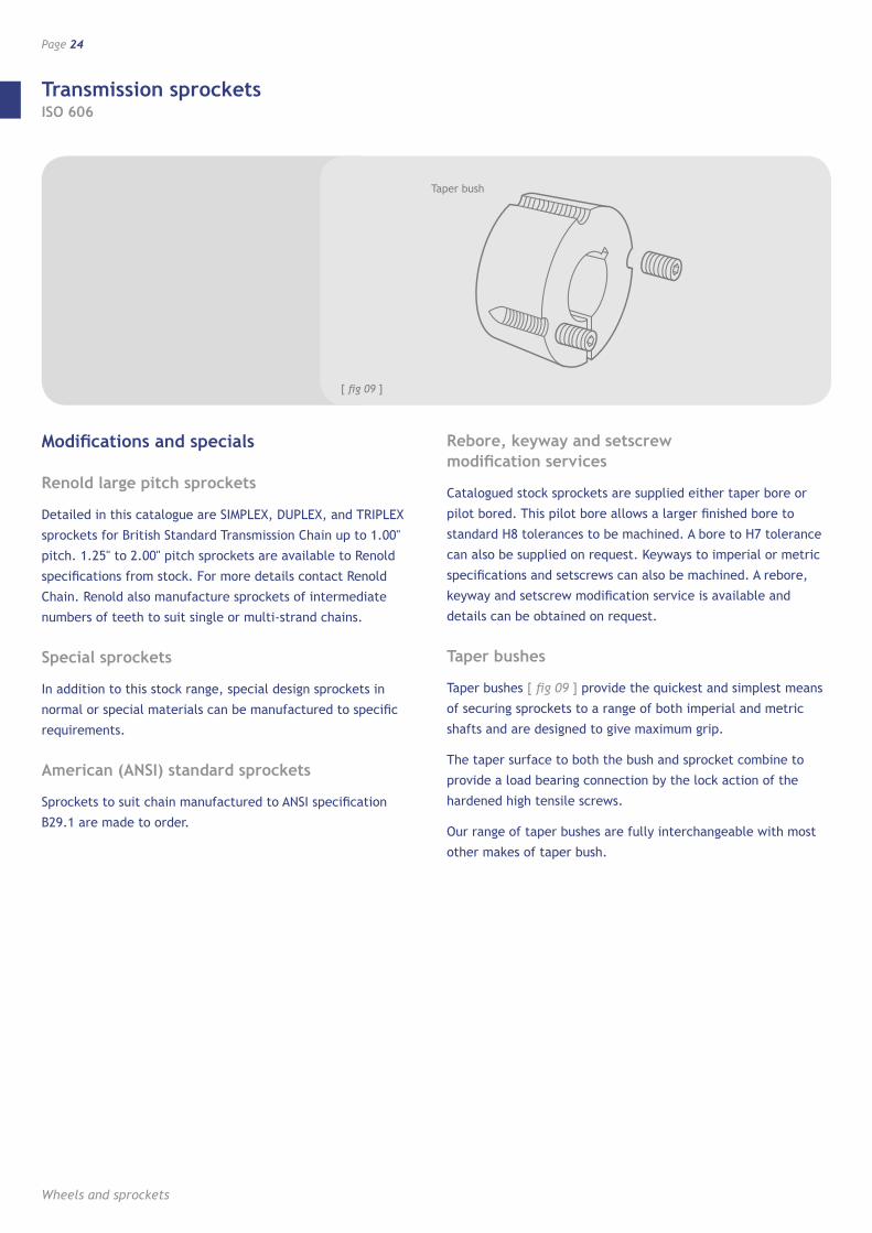
Taper bushes
Taper bushes [ fig 09 ] provide the quickest and simplest means
of securing sprockets to a range of both imperial and metric
shafts and are designed to give maximum grip.
The taper surface to both the bush and sprocket combine to
provide a load bearing connection by the lock action of the
hardened high tensile screws.
Our range of taper bushes are fully interchangeable with most
other makes of taper bush.
Taper bush
Transmission sprockets ISO 606
www.renold.com
Page 25
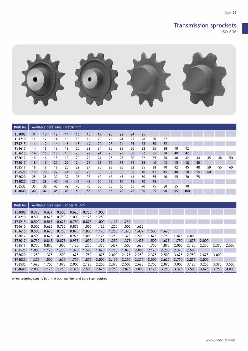
Bush No
TB1008 TB1210 TB1215 TB1610 TB1615 TB2012 TB2017 TB2517 TB2525 TB3020 TB3030 TB3535 TB4040
9 11 11 14 14 14 18 16 19 25 35 35 40
10 12 12 16 16 16 19 18 20 28 38 38 42
12 14 14 18 18 18 20 19 22 30 40 40 45
14 16 16 19 19 19 22 20 24 32 42 42 48
16 18 18 20 20 20 24 22 25 35 45 45 50
18 19 19 22 22 22 25 24 28 38 48 48 55
19 20 20 24 24 24 28 25 30 40 50 50 60
20 22 22 25 25 25 30 28 32 42 55 55 65
22 24 24 28 28 28 32 30 35 45 60 60 70
24 25 25 30 30 30 35 32 38 48 65 65 75
25 28 28 32 32 32 38 35 40 50 70 70 80
30 30 35 35 35 40 38 42 55 75 75 85
32 32 38 38 38 42 40 45 60
80 90
40 40 40 45 42 48 65
85 95
42 42 42 48 45 50 70
90 100
44 50 48 55 75
45
50 60
48
55
50
60
Available bore sizes – metric mm
Bush No
TB1008 TB1210 TB1215 TB1610 TB1615 TB2012 TB2017 TB2517 TB2525 TB3020 TB3030 TB3535 TB4040
0.375 0.500 0.500 0.500 0.500 0.500 0.750 0.750 1.000 1.250 1.375 1.625 2.000
0.437 0.625 0.562 0.625 0.625 0.625 0.812 0.875 1.125 1.375 1.500 1.750 2.125
0.500 0.750 0.625 0.750 0.750 0.750 0.875 1.000 1.250 1.500 1.625 1.875 2.250
0.625 1.000 0.750 0.875 0.875 0.975 0.937 1.125 1.375 1.625 1.750 2.000 2.375
0.750 1.125 0.875 1.000 1.000 1.000 1.000 1.250 1.500 1.750 1.875 2.125 2.500
1.000 1.250 1.000 1.125 1.125 1.125 1.125 1.375 1.625 1.875 2.000 2.250 2.625
1.125 1.250 1.250 1.250 1.250 1.437 1.750 2.000 2.125 2.375 2.750
1.250 1.500 1.375 1.375 1.375 1.500 1.875 2.125 2.250 2.500 2.875
1.625 1.437 1.500 1.437 1.625 2.000 2.250 2.375 2.625 3.000
1.500 1.625 1.500 1.750 2.125 2.375 2.500 2.750 3.125
1.625 1.750 1.625 1.875 2.250 2.500 2.625 2.875 3.250
1.875 1.750 2.000 2.375 3.625 2.750 3.000 3.375
2.000 1.875 2.125 2.500 2.750 2.875 3.125 3.500
2.000 2.250 2.875 3.000 3.250 3.625
2.375 3.000 3.375 3.750
2.500 3.500 4.000
Available bore sizes – imperial inch
When ordering specify both the bush number and bore size required.

Transmission sprockets Notes
Wheels and sprockets
Page 26

Standard conveyor sprockets
Page 27
www.renold.com
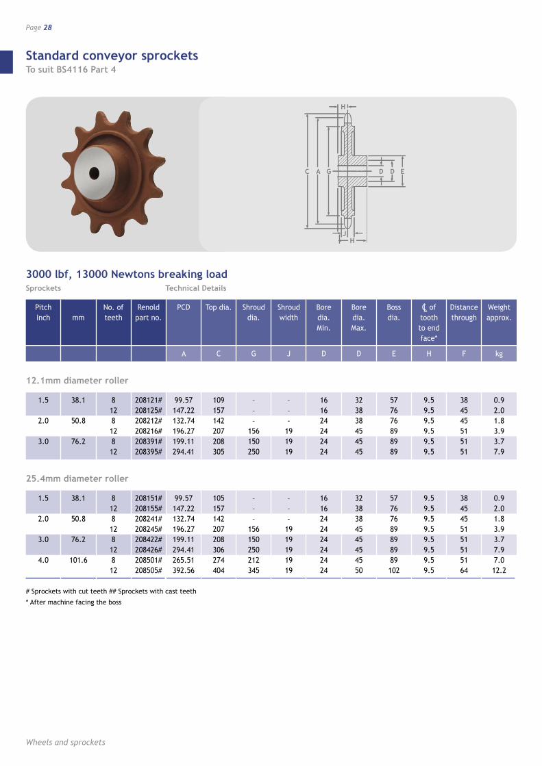
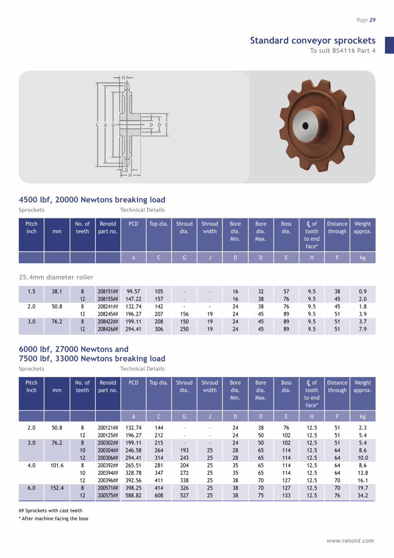
Standard conveyor sprockets To suit BS4116 Part 4
Wheels and sprockets
Page 28
C GA D ED
H
JH
1.5
2.0
3.0
4.0
38.1
50.8
76.2
101.6
812812812812
208151#208155#208241#208245#208422#208426#208501#208505#
99.57147.22132.74196.27199.11294.41265.51392.56
105157142207208306274404
–––
156150250212345
––-
1919191919
1616242424242424
3238384545454550
57767689898989102
9.59.59.59.59.59.59.59.5
3845455151515164
0.92.01.83.93.77.97.012.2
1.5
2.0
3.0
38.1
50.8
76.2
812812812
208121#208125#208212#208216#208391#208395#
99.57147.22132.74196.27199.11294.41
109157142207208305
–––
156150250
––-
191919
161624242424
323838454545
577676898989
9.59.59.59.59.59.5
384545515151
0.92.01.83.93.77.9
12.1mm diameter roller
25.4mm diameter roller
3000 lbf, 13000 Newtons breaking loadSprockets Technical Details
# Sprockets with cut teeth ## Sprockets with cast teeth
* After machine facing the boss
Pitch Inch
mm
No. of teeth
Renold part no.
PCD
A
Top dia.
C
Shroud dia.
G
Shroud width
J
Bore dia. Min.
D
Bore dia. Max.
D
Boss dia.
E
CL of tooth to end face*
H
Distance through
F
Weight approx.
kg
Standard conveyor sprockets To suit BS4116 Part 4
www.renold.com
Page 29
C GA D ED
H
JH
1.5
2.0
3.0
38.1
50.8
76.2
812812812
208151##208155##208241##208245##208422##208426##
99.57147.22132.74196.27199.11294.41
105157142207208306
–––
156150250
––-
191919
161624242424
323838454545
577676898989
9.59.59.59.59.59.5
384545515151
0.9 2.0 1.8 3.9 3.7 7.9
25.4mm diameter roller
6000 lbf, 27000 Newtons and7500 lbf, 33000 Newtons breaking loadSprockets Technical Details
4500 lbf, 20000 Newtons breaking loadSprockets Technical Details
2.0
3.0
4.0
6.0
50.8
76.2
101.6
152.4
812810 12810 12 8 12
200121##200125##200302##200304##200306##200392## 200394## 200396## 200571## 200575##
132.74196.27199.11 246.58294.41265.51 328.78392.56 398.25 588.82
144212215264314281347411 414 608
–––
193243204272338 326 527
––-
25 25 25 25 25 25 25
2424242828 35 3538 38 38
3850 50 65 65 65 65 70 70 75
76102 102 114 114 114 114 127 127 133
12.512.512.512.512.512.512.512.5 12.5 12.5
51515164 64 64 64 70 70 76
2.3 5.45.4 8.6 10.0 8.6 13.8 16.1 19.7 34.2
## Sprockets with cast teeth
* After machine facing the boss
Pitch Inch
mm
No. of teeth
Renold part no.
PCD
A
Top dia.
C
Shroud dia.
G
Shroud width
J
Bore dia. Min.
D
Bore dia. Max.
D
Boss dia.
E
CL of tooth to end face*
H
Distance through
F
Weight approx.
kg
Pitch Inch
mm
No. of teeth
Renold part no.
PCD
A
Top dia.
C
Shroud dia.
G
Shroud width
J
Bore dia. Min.
D
Bore dia. Max.
D
Boss dia.
E
CL of tooth to end face*
H
Distance through
F
Weight approx.
kg
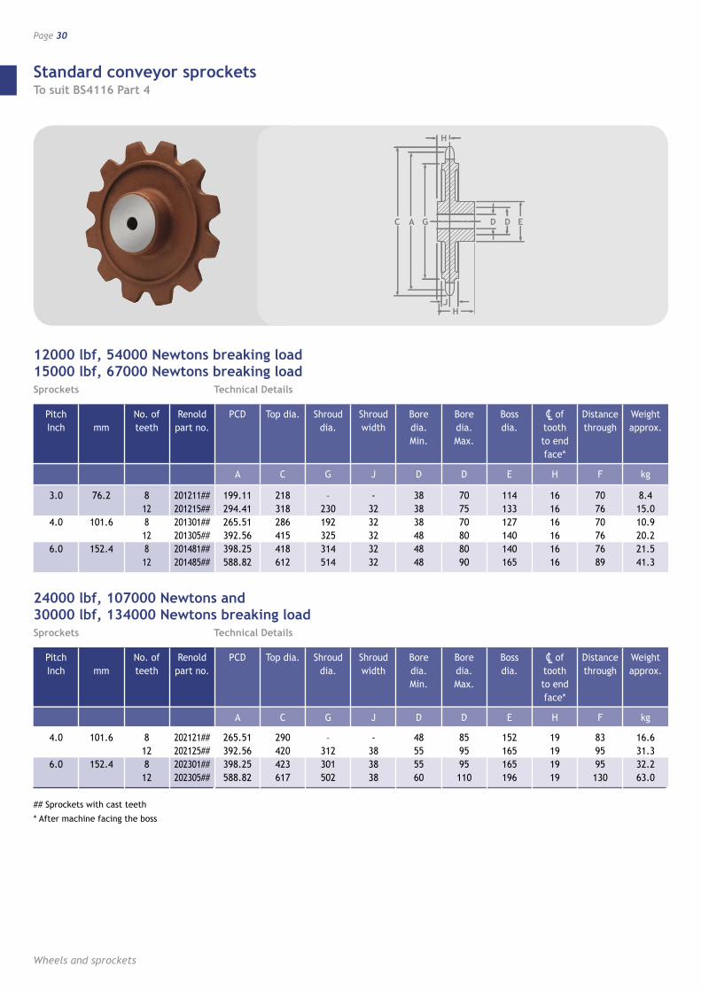
Standard conveyor sprockets To suit BS4116 Part 4
Wheels and sprockets
Page 30
12000 lbf, 54000 Newtons breaking load15000 lbf, 67000 Newtons breaking loadSprockets Technical Details
3.0
4.0
6.0
76.2
101.6
152.4
812812812
201211##201215##201301##201305##201481##201485##
199.11294.41265.51392.56398.25588.82
218318286415418612
–230192325314514
-3232323232
383838484848
707570808090
114133127140140165
161616161616
707670767689
8.415.010.920.221.541.3
24000 lbf, 107000 Newtons and30000 lbf, 134000 Newtons breaking loadSprockets Technical Details
4.0
6.0
101.6
152.4
812812
202121##202125##202301##202305##
265.51 392.56 398.25 588.82
290420423617
–312301502
-383838
48555560
859595110
152165165196
19191919
839595130
16.6 31.332.263.0
## Sprockets with cast teeth
* After machine facing the boss
C GA D ED
H
JH
Pitch Inch
mm
No. of teeth
Renold part no.
PCD
A
Top dia.
C
Shroud dia.
G
Shroud width
J
Bore dia. Min.
D
Bore dia. Max.
D
Boss dia.
E
CL of tooth to end face*
H
Distance through
F
Weight approx.
kg
Pitch Inch
mm
No. of teeth
Renold part no.
PCD
A
Top dia.
C
Shroud dia.
G
Shroud width
J
Bore dia. Min.
D
Bore dia. Max.
D
Boss dia.
E
CL of tooth to end face*
H
Distance through
F
Weight approx.
kg
Standard conveyor sprockets Notes
www.renold.com
Page 31
Wheels and sprockets
Page 32
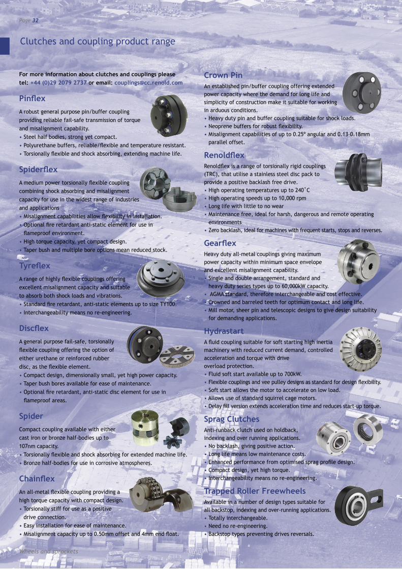
For more information about clutches and couplings please tel: +44 (0)29 2079 2737 or email: [email protected]
PinflexA robust general purpose pin/buffer coupling providing reliable fail-safe transmission of torque and misalignment capability.• Steel half bodies, strong yet compact.• Polyurethane buffers, reliable/flexible and temperature resistant.• Torsionally flexible and shock absorbing, extending machine life.
SpiderflexA medium power torsionally flexible coupling combining shock absorbing and misalignment capacity for use in the widest range of industries and applications• Misalignment capabilities allow flexibility in installation.• Optional fire retardant anti-static element for use in
flameproof environment.• High torque capacity, yet compact design.• Taper bush and multiple bore options mean reduced stock.
TyreflexA range of highly flexible couplings offering excellent misalignment capacity and suitable to absorb both shock loads and vibrations.• Standard fire retardant, anti-static elements up to size TY100.• Interchangeability means no re-engineering.
DiscflexA general purpose fail-safe, torsionally flexible coupling offering the option of either urethane or reinforced rubber disc, as the flexible element.• Compact design, dimensionally small, yet high power capacity.• Taper bush bores available for ease of maintenance.• Optional fire retardant, anti-static disc element for use in
flameproof areas.
SpiderCompact coupling available with either cast iron or bronze half-bodies up to 107nm capacity.• Torsionally flexible and shock absorbing for extended machine life.• Bronze half-bodies for use in corrosive atmospheres.
ChainflexAn all-metal flexible coupling providing a high torque capacity with compact design.• Torsionally stiff for use as a positive
drive connection.• Easy installation for ease of maintenance.• Misalignment capacity up to 0.50mm offset and 4mm end float.
Crown PinAn established pin/buffer coupling offering extended power capacity where the demand for long life and simplicity of construction make it suitable for working in arduous conditions.• Heavy duty pin and buffer coupling suitable for shock loads.• Neoprene buffers for robust flexibility.• Misalignment capabilities of up to 0.25º angular and 0.13–0.18mm
parallel offset.
RenoldflexRenoldflex is a range of torsionally rigid couplings (TRC), that utilise a stainless steel disc pack to provide a positive backlash free drive.• High operating temperatures up to 240˚C • High operating speeds up to 10,000 rpm • Long life with little to no wear • Maintenance free, ideal for harsh, dangerous and remote operating
environments • Zero backlash, ideal for machines with frequent starts, stops and reverses.
GearflexHeavy duty all-metal couplings giving maximum power capacity within minimum space envelope and excellent misalignment capability.• Single and double arrangement, standard and
heavy duty series types up to 60,000kW capacity.• AGMA standard, therefore interchangeable and cost effective.• Crowned and barreled teeth for optimum contact and long life.• Mill motor, sheer pin and telescopic designs to give design suitability
for demanding applications.
HydrastartA fluid coupling suitable for soft starting high inertia machinery with reduced current demand, controlled acceleration and torque with drive overload protection.• Fluid soft start available up to 700kW.• Flexible couplings and vee pulley designs as standard for design flexibility.• Soft start allows the motor to accelerate on low load.• Allows use of standard squirrel cage motors.• Delay fill version extends acceleration time and reduces start-up torque.
Sprag ClutchesAnti-runback clutch used on holdback, indexing and over running applications.• No backlash, giving positive action.• Long life means low maintenance costs.• Enhanced performance from optimised sprag profile design.• Compact design, yet high torque.• Interchangeability means no re-engineering.
Trapped Roller FreewheelsAvailable in a number of design types suitable for all backstop, indexing and over-running applications.• Totally interchangeable.• Need no re-engineering.• Backstop types preventing drives reversals.
Clutches and coupling product range
www.renold.com
AUSTRALIA Melbourne (Victoria) Tel + 61 (03) 9262 3333 Fax + 61 (03) 9561 8561 also at: Sydney, Brisbane, Adelaide, Perth, Newcastle, Wollongong, Townsville
AUSTRIA Vienna Tel + 43 (0) 13303484 0 Fax + 43 (0) 13303484 5
BELGIUM Brussels Tel + 32 (0) 2 201 1262 Fax + 32 (0) 2 203 2210
CANADA Brantford (Ontario) Tel + 1 519 756 6118 Fax + 1 519 756 1767 also at: Montreal
CHINA Shanghai Tel + 86 21 5046 2696 Fax + 86 21 5046 2695
CZECH REPUBLIC Jaroslavice Tel + 42 67 7211074 Fax + 42 67 7211074
DENMARK Brøndby (Copenhagen) Tel + 45 43 452611 Fax + 45 43 456592
FRANCE Seclin Tel + 33 (0) 320 16 29 29 Fax + 33 (0) 320 16 29 00 Calais (chain only) Tel + 33 (0) 321 97 99 45 Fax + 33 (0) 321 97 83 45
GERMANY Mechernich Tel + 49 (0) 2256 95 90 74 Fax + 49 (0) 2256 95 91 69 [email protected]
HUNGARY Havasi Janos Tel + 36 (0) 78 312483 Fax + 36 (0) 78 312483
MALAYSIA Petaling Jaya Tel + 603 5191 9880 Fax + 603 5191 9881 also at: Johor Bharu, Ipoh, Butterworth
NETHERLANDS Amsterdam Tel + 31 206 146661 Fax + 31 206 146391
NEW ZEALAND Auckland Tel + (0) 64 9 828 5018 Fax + (0) 64 9 828 5019 also at: Christchurch
SINGAPORE Singapore Tel + 65 6760 2422 Fax + 65 6760 1507
SOUTH AFRICA Benoni Tel + (0) 27 11 845 1535 Fax + (0) 27 11 421 9289 also at: Durban, Cape Town, Port Elizabeth, Witbank
SPAIN Renold Hi-Tec Couplings SA Tel + 34 93 6380558 Fax + 34 93 6380737 [email protected]
SWEDEN Brøndby (Copenhagen) Tel + 45 43 245028 Fax + 45 43 456592
SWITZERLAND Dübendorf (Zürich) Tel + 41 (0) 1 824 8484 Fax + 41 (0) 1 824 8411 also at: Crissier (Lausanne)
UK Renold Clutches & Couplings, Wales Tel + 44 (0) 29 20792737 Fax + 44 (0) 29 20791360 [email protected]
Renold Hi-Tec Couplings, Halifax Tel + 44 (0) 1422 255000 Fax + 44 (0) 1422 320273 [email protected]
USA Renold Ajax Westfield, New York Tel + 1 716 326 3121 Fax + 1 716 326 6121
WEB www.renold.com
E-MAIL [email protected]
For other country distributors please contact Renold UK or visit the renold website.
Whilst all reasonable care in compiling the information contained in this brochure is taken, no responsibility is accepted for printing errors. All information contained in this brochure is subject to change after the date of publication.