Embed Size (px)
Citation preview
0054 - 1
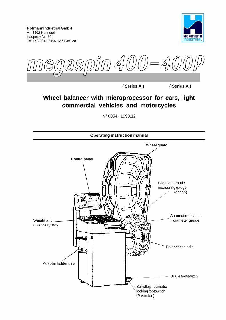
( Series A ) ( Series A )
Wheel balancer with microprocessor for cars, lightcommercial vehicles and motorcycles
N° 0054 - 1998.12
Operating instruction manual
HofmannIndustrial GmbHA - 5302 HenndorfHauptstraße 59Tel +43-6214-6466-12 \ Fax -20
Control panel
Wheel guard
Weight andaccessory tray
Adapter holder pins
Balancer spindle
Automatic distance+ diameter gauge
Width automaticmeasuring gauge
(option)
Brake footswitch
Spindle pneumaticlocking footswitch(P version)

2 - 0054
Note: Due to international agreements this machine may not be sold in the following countries:
France, Germany, Italy, USA
0054 - 3
INDEX1 - GENERAL ............................................................................................................................................................... 5
1.1 - GENERAL SAFETY REGULATIONS ............................................................................................ 51.1.1 - STANDARD SAFETY DEVICES ................................................................................................ 51.2 - FIELD OF APPLICATION .............................................................................................................. 51.3 - OVERALL DIMENSIONS .............................................................................................................. 51.4 - SPECIFICATION .......................................................................................................................... 6
2 - HANDLING, HOISTING ...................................................................................................................................... 63 - START-UP................................................................................................................................................................ 6
3.1 - ANCHORING ................................................................................................................................................... 63.2 - ELECTRICAL CONNECTION ....................................................................................................................... 63.3 - PNEUMATIC CONNECTION (P version only) ..................................................................................73.3.1 - FURTHER SAFETY DEVICES .................................................................................................................. 73.4 - ADAPTER MOUNTING................................................................................................................................... 73.5 - WHEEL GUARD ASSEMBLY AND ADJUSTMENT ..........................................................................7
4 - CONTROLS AND COMPONENTS ................................................................................................................ 84.1 - BRAKE FOOTSWITCH ................................................................................................................................. 84.2 - PNEUMATIC LOCKING FOOTSWITCH (VERSION P) ............................................................................ 84.3 - AUTOMATIC DISTANCE AND DIAMETER GAUGE .................................................................................. 84.4 - MANUAL RIM DISTANCE GAUGE (OPTION) ............................................................................................ 84.5 - AUTOMATIC WHEEL POSITIONING........................................................................................................... 84.6 - CONTROL PANEL AND DISPLAY ................................................................................................. 94.6.1 - HANDLING OF THE FUNCTIONS MENU ................................................................................... 10
5 - INDICATIONS AND USE OF THE WHEEL BALANCER ..................................................................... 115.1 - DOUBLE OPERATOR PROGRAM ............................................................................................................ 115.2 - PRESETTING OF WHEEL DIMENSIONS ................................................................................................. 115.2.1 - AUTOMATIC PRESETTING ...................................................................................................................... 115.2.1.1 - AUTOMATIC WIDTH" OPTION ............................................................................................................. 125.2.1.2 - ALU-M WHEEL ........................................................................................................................................ 135.2.2 - MANUAL PRESETTING.............................................................................................................. 135.3 - RECALCULATION OF THE UNBALANCE................................................................................................. 145.4 - RESULT OF MEASUREMENT ....................................................................................................................155.4.1 - INDICATION OF EXACT CORRECTION POSITION IN ALU-M ...........................................................155.4.2 - RESOLUTION OF THE UNBALANCE (SPLIT) ........................................................................... 175.4.3 - UNBALANCE OPTIMIZATION ................................................................................................................... 185.4.4 - ALU AND STATIC MODES .......................................................................................................................195.4.5 - AUTOMATIC MINIMIZATION OF STATIC UNBALANCE .......................................................................19
6 - SET UP ..................................................................................................................................................................... 206.1 - SELF-DIAGNOSTICS .................................................................................................................................... 206.2 - SELF-CALIBRATION ..................................................................................................................................... 216.3 - AUTOMATIC GAUGES .................................................................................................................................. 226.3.1 - DISTANCE GAUGE .................................................................................................................................... 226.3.2 - DIAMETER GAUGE .................................................................................................................................... 226.3.3 - WIDTH GAUGE (OPTION) ........................................................................................................................ 23
7 - ERRORS .................................................................................................................................................................. 247.1 - INCONSISTENT UNBALANCE READINGS ................................................................................. 24
8 - ROUTINE MAINTENANCE .................................................................................................. 248.1 - REPLACEMENT OF THE FUSES ..............................................................................................................248.2 - ADAPTER TERMINAL OF P SPINDLE ...................................................................................................... 24
- EXPLODED DRAWINGS- CE-CERTIFICATE OF CONFORMITY

4 - 0054
0054 - 5
1 - GENERAL
1.1 - GENERAL SAFETY REGULATIONS- The machine should only be used by authorized and suitably trained personnel.- Do not use the machine for purposes other than those specified in this manual.- The machine should not be modified in any way except for those modifications explicitly carried out
by the manufacturer.- Never remove the safety devices. Any work on the machine should only be carried out by specialist
personnel.- Avoid using strong jets of compressed air for cleaning.- Use alcohol to clean the plastic panel or shelves (AVOID LIQUIDS CONTAINING SOLVENTS).- Before starting the wheel balancing cycle, make sure that the wheel is securely locked on the adapter.- The machine operator should avoid wearing clothes with flapping edges. Make sure that unauthorized
personnel do not approach the machine during the work cycle.- Avoid placing objects inside the base as they could impair the correct operation of the machine.
1.1.1 - STANDARD SAFETY DEVICES- Stop push button for stopping the wheel under emergency conditions.- The plastic safety guard of high impact strength is with shape and size designed to avoid risk of
counterweights from flying out in any direction except towards the floor.- A microswitch prevents the machine from starting if the guard is not lowered and it stops the
motor when the guard is raised.
1.2 - FIELD OF APPLICATIONThe machine is designed for balancing wheels of cars, light commercial vehicles or motorcycles, weighingless than 65 kg. It can be operated in the temperature range of -10°C to +45°C.The following functions are provided: Double operator; ALU-M automatic; SPLIT; Unbalance optimization;Self diagnostics; Self calibration
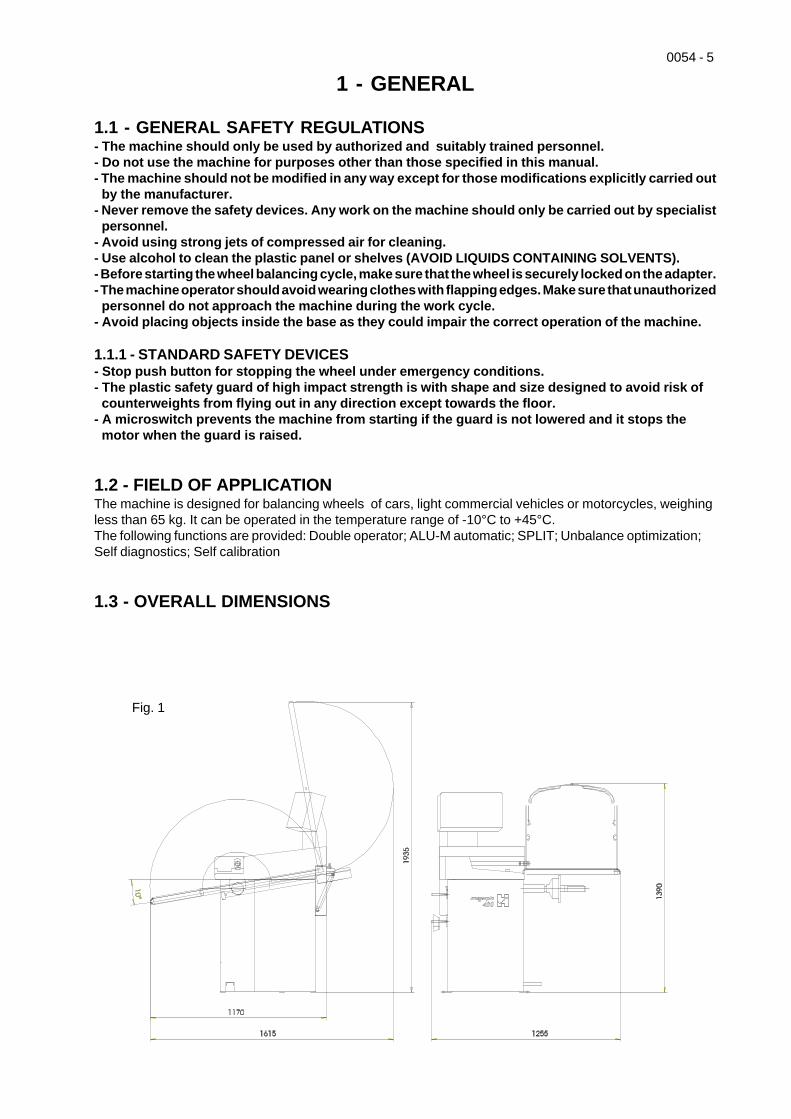
1.3 - OVERALL DIMENSIONS
Fig. 1
6 - 0054
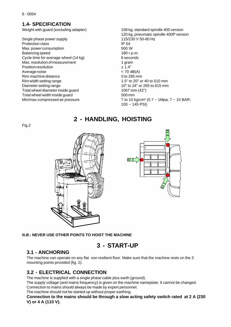
1.4- SPECIFICATIONWeight with guard (excluding adapter) 108 kg, standard spindle 400 version
120 kg, pneumatic spindle 400P versionSingle phase power supply 115/230 V 50-60 HzProtection class IP 54Max. power consumption 500 WBalancing speed 180 r.p.m.Cycle time for average wheel (14 kg) 6 secondsMax. resolution of measurement 1 gramPosition resolution ± 1.4°Average noise < 70 dB(A)Rim-machine distance 0 to 285 mmRim width setting range 1.5" to 20" or 40 to 510 mmDiameter setting range 10" to 24" or 265 to 615 mmTotal wheel diameter inside guard 1067 mm (42")Total wheel width inside guard 500 mmMin/max compressed air pressure 7 to 10 kg/cm² (0.7 ~ 1Mpa; 7 ~ 10 BAR;
100 ~ 145 PSI)
2 - HANDLING, HOISTINGFig.2
N.B.: NEVER USE OTHER POINTS TO HOIST THE MACHINE
3 - START-UP3.1 - ANCHORINGThe machine can operate on any flat non resilient floor. Make sure that the machine rests on the 3mounting points provided (fig. 2).
3.2 - ELECTRICAL CONNECTIONThe machine is supplied with a single phase cable plus earth (ground).The supply voltage (and mains frequency) is given on the machine nameplate. It cannot be changed.Connection to mains should always be made by expert personnel.The machine should not be started up without proper earthing.Connection to the mains should be through a slow acting safety switch rated at 2 A (230V) or 4 A (110 V).
0054 - 7
3.3 - PNEUMATIC CONNECTION (P version only)For the operation of the spindle with pneumatic locking, (constant thrust gas springs) connect the machineto the compressed air mains. The connection fitting is on the rear of the machine. At least 7 kg/cm²(~0.7Mpa; ~ 7 BAR; ~ 100 PSI) are required for the correct operation of the locking device.
3.3.1 - FURTHER SAFETY DEVICES- The wheel is always locked also in the event of insufficient pressure during the balancing cycle.- A wheel check device with rotating block which prevents the wheel for slipping off the adapter in
the event of accidental pressure on the wheel locking footswitch during the cycle. Always actuatethe unlocking footswitch when the machine is stationary in order to avoid stress and abnormalwear on the adapter.
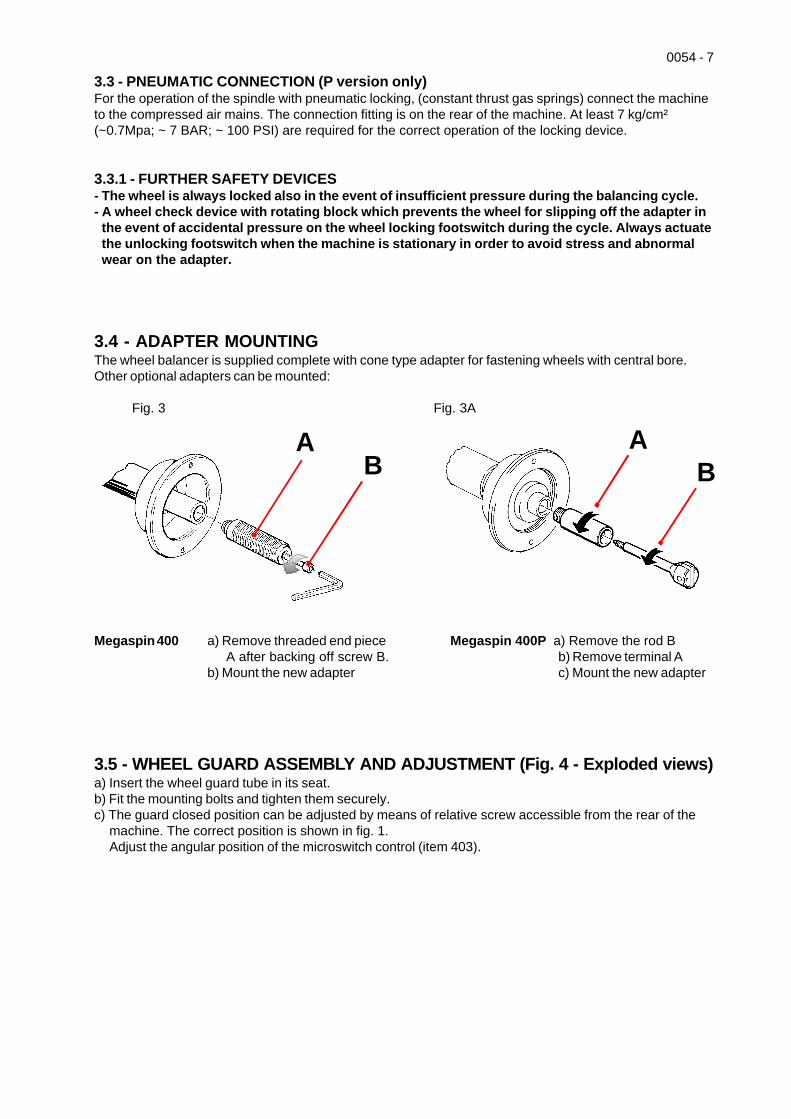
3.4 - ADAPTER MOUNTINGThe wheel balancer is supplied complete with cone type adapter for fastening wheels with central bore.Other optional adapters can be mounted:
Fig. 3 Fig. 3A
AB
AB
Megaspin 400 a) Remove threaded end pieceA after backing off screw B.
b) Mount the new adapter
Megaspin 400P a) Remove the rod Bb) Remove terminal Ac) Mount the new adapter
3.5 - WHEEL GUARD ASSEMBLY AND ADJUSTMENT (Fig. 4 - Exploded views)a) Insert the wheel guard tube in its seat.b) Fit the mounting bolts and tighten them securely.c) The guard closed position can be adjusted by means of relative screw accessible from the rear of the
machine. The correct position is shown in fig. 1.Adjust the angular position of the microswitch control (item 403).
8 - 0054
4 - CONTROLS AND COMPONENTS
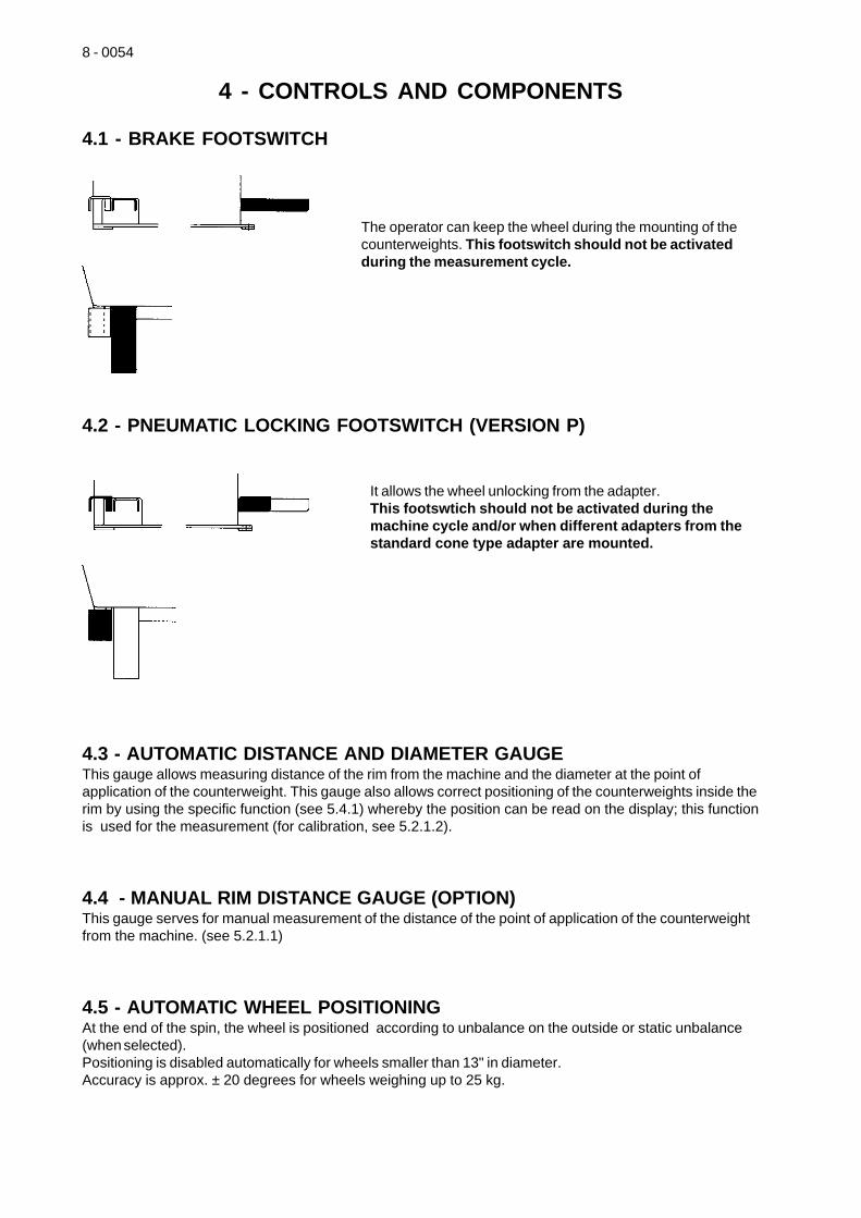
4.1 - BRAKE FOOTSWITCH
The operator can keep the wheel during the mounting of thecounterweights. This footswitch should not be activatedduring the measurement cycle.
4.2 - PNEUMATIC LOCKING FOOTSWITCH (VERSION P)
It allows the wheel unlocking from the adapter.This footswtich should not be activated during themachine cycle and/or when different adapters from thestandard cone type adapter are mounted.
4.3 - AUTOMATIC DISTANCE AND DIAMETER GAUGEThis gauge allows measuring distance of the rim from the machine and the diameter at the point ofapplication of the counterweight. This gauge also allows correct positioning of the counterweights inside therim by using the specific function (see 5.4.1) whereby the position can be read on the display; this functionis used for the measurement (for calibration, see 5.2.1.2).
4.4 - MANUAL RIM DISTANCE GAUGE (OPTION)This gauge serves for manual measurement of the distance of the point of application of the counterweightfrom the machine. (see 5.2.1.1)
4.5 - AUTOMATIC WHEEL POSITIONINGAt the end of the spin, the wheel is positioned according to unbalance on the outside or static unbalance(when selected).Positioning is disabled automatically for wheels smaller than 13" in diameter.Accuracy is approx. ± 20 degrees for wheels weighing up to 25 kg.
0054 - 9
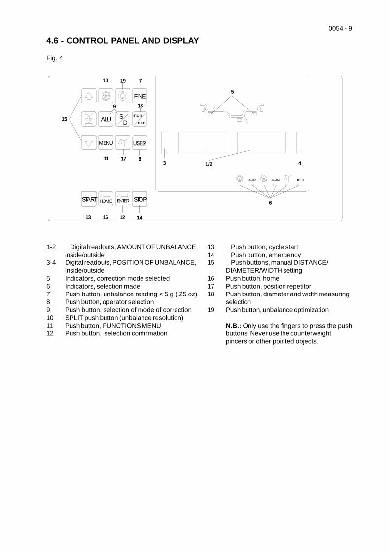
4.6 - CONTROL PANEL AND DISPLAY
Fig. 4
1-2 Digital readouts, AMOUNT OF UNBALANCE,inside/outside
3-4 Digital readouts, POSITION OF UNBALANCE,inside/outside
5 Indicators, correction mode selected6 Indicators, selection made7 Push button, unbalance reading < 5 g (.25 oz)8 Push button, operator selection9 Push button, selection of mode of correction10 SPLIT push button (unbalance resolution)11 Push button, FUNCTIONS MENU12 Push button, selection confirmation
13 Push button, cycle start14 Push button, emergency15 Push buttons, manual DISTANCE/
DIAMETER/WIDTH setting16 Push button, home17 Push button, position repetitor18 Push button, diameter and width measuring
selection19 Push button, unbalance optimization
N.B.: Only use the fingers to press the pushbuttons. Never use the counterweightpincers or other pointed objects.
USER 2 ALU M mm
FINE
ALU SD
inch
mm
MENU STOP
START HOME ENTER STOP
1/23
5
6
7
8
9
10
11
1213 14
15
16
17
18
19
4
10 - 0054
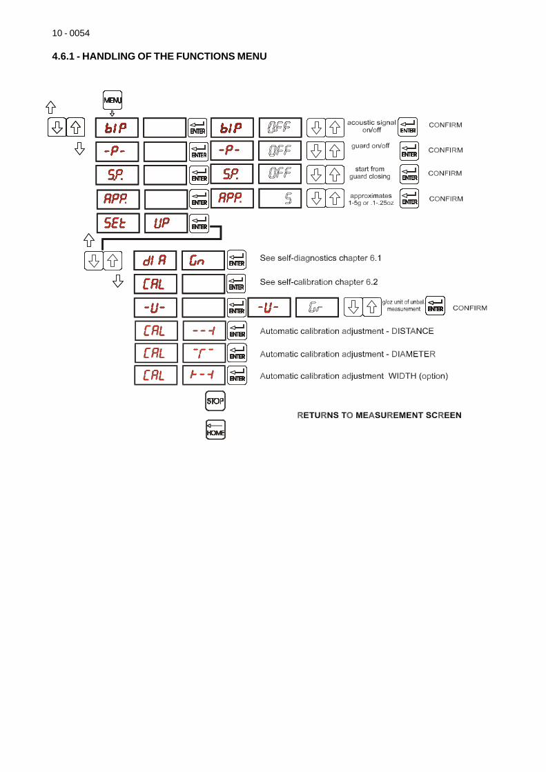
4.6.1 - HANDLING OF THE FUNCTIONS MENU
0054 - 11
5 - INDICATIONS AND USE OF THE WHEEL BALANCER5.1 - DOUBLE OPERATOR PROGRAMThis program allows memorizing the dimensions of two types of wheels. Thus two operators can worksimultaneously on two different cars using the same balancing machine. The system memorizes twoprograms with various preset dimensions.
1 - Press to select operator (1 or 2). Selection is confirmed by panel-mounted LED.
2 - Enter the dimensions (see 5.2)
3 - Press to carry out the balancing as usual and memorize the programme
With program 1 or 2 is called for subsequent balancing operations without having to newly enter
the dimensions.
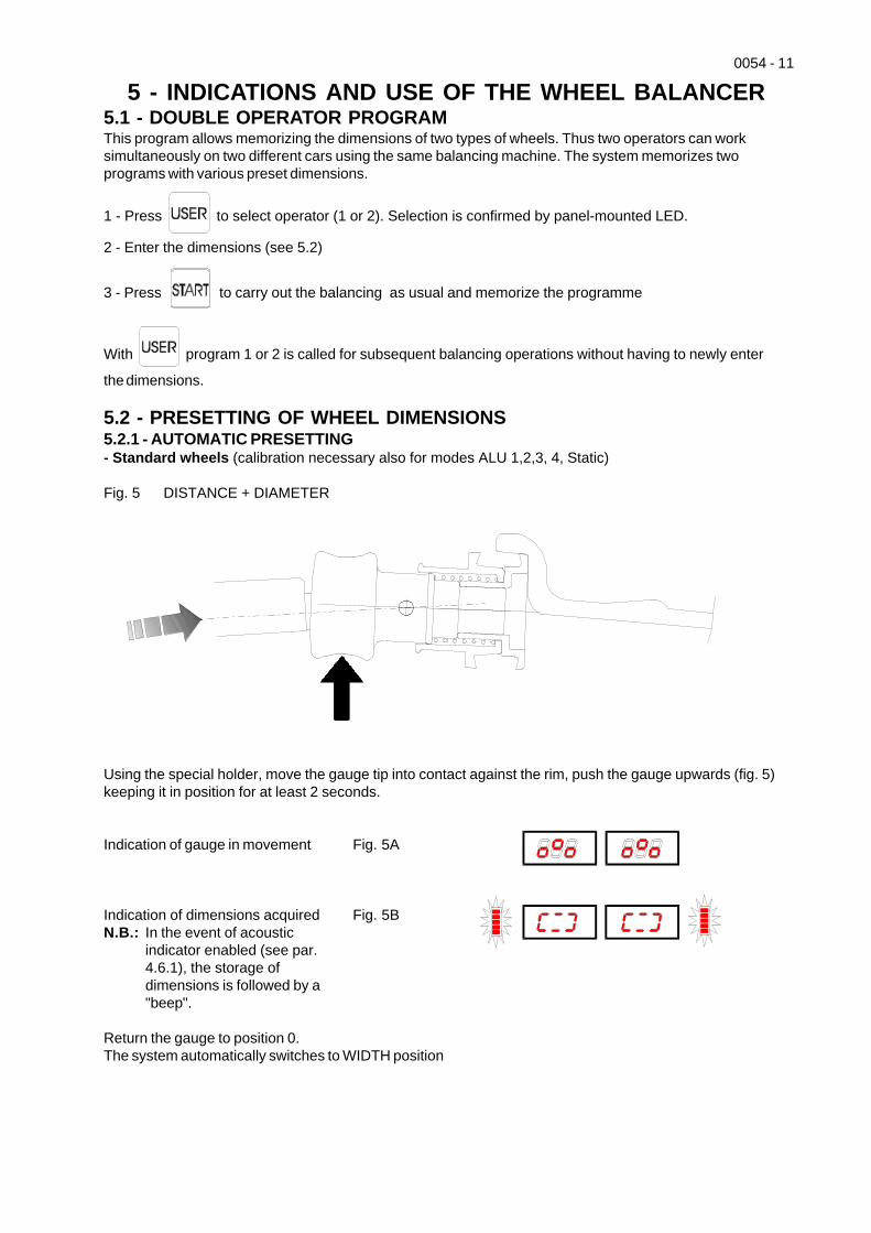
5.2 - PRESETTING OF WHEEL DIMENSIONS5.2.1 - AUTOMATIC PRESETTING- Standard wheels (calibration necessary also for modes ALU 1,2,3, 4, Static)
Fig. 5 DISTANCE + DIAMETER
Using the special holder, move the gauge tip into contact against the rim, push the gauge upwards (fig. 5)keeping it in position for at least 2 seconds.
Indication of gauge in movement Fig. 5A
Indication of dimensions acquired Fig. 5BN.B.: In the event of acoustic
indicator enabled (see par.4.6.1), the storage ofdimensions is followed by a"beep".
Return the gauge to position 0.The system automatically switches to WIDTH position
12 - 0054
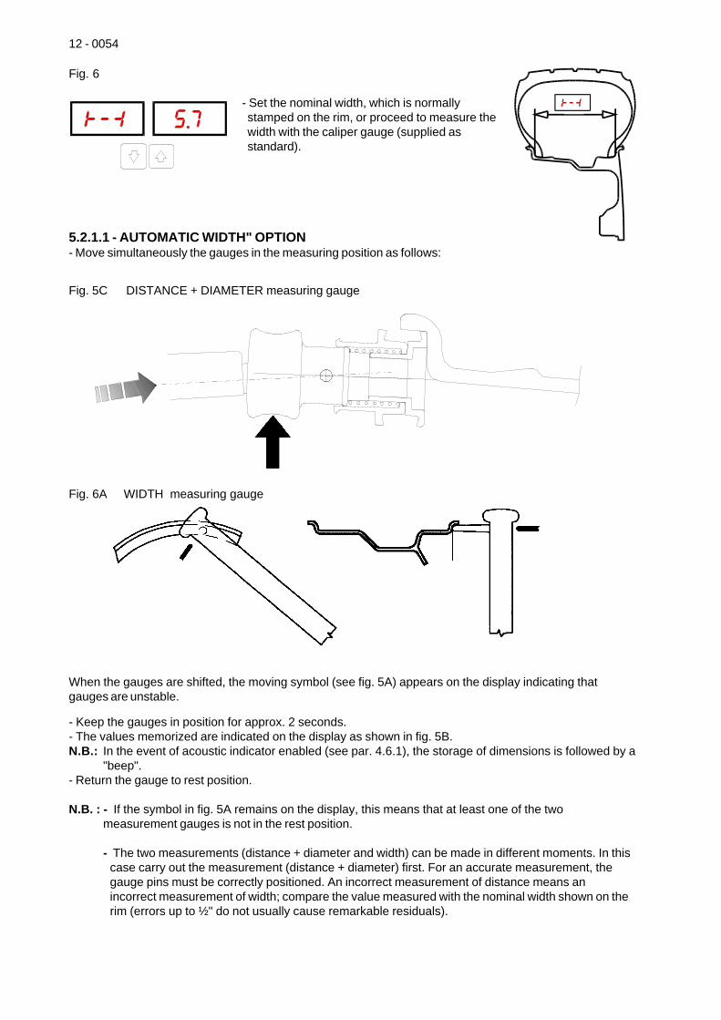
Fig. 6
- Set the nominal width, which is normallystamped on the rim, or proceed to measure thewidth with the caliper gauge (supplied asstandard).
5.2.1.1 - AUTOMATIC WIDTH" OPTION- Move simultaneously the gauges in the measuring position as follows:
Fig. 5C DISTANCE + DIAMETER measuring gauge
Fig. 6A WIDTH measuring gauge
When the gauges are shifted, the moving symbol (see fig. 5A) appears on the display indicating thatgauges are unstable.
- Keep the gauges in position for approx. 2 seconds.- The values memorized are indicated on the display as shown in fig. 5B.N.B.: In the event of acoustic indicator enabled (see par. 4.6.1), the storage of dimensions is followed by a
"beep".- Return the gauge to rest position.
N.B. : - If the symbol in fig. 5A remains on the display, this means that at least one of the twomeasurement gauges is not in the rest position.
- The two measurements (distance + diameter and width) can be made in different moments. In thiscase carry out the measurement (distance + diameter) first. For an accurate measurement, thegauge pins must be correctly positioned. An incorrect measurement of distance means anincorrect measurement of width; compare the value measured with the nominal width shown on therim (errors up to ½" do not usually cause remarkable residuals).
0054 - 13
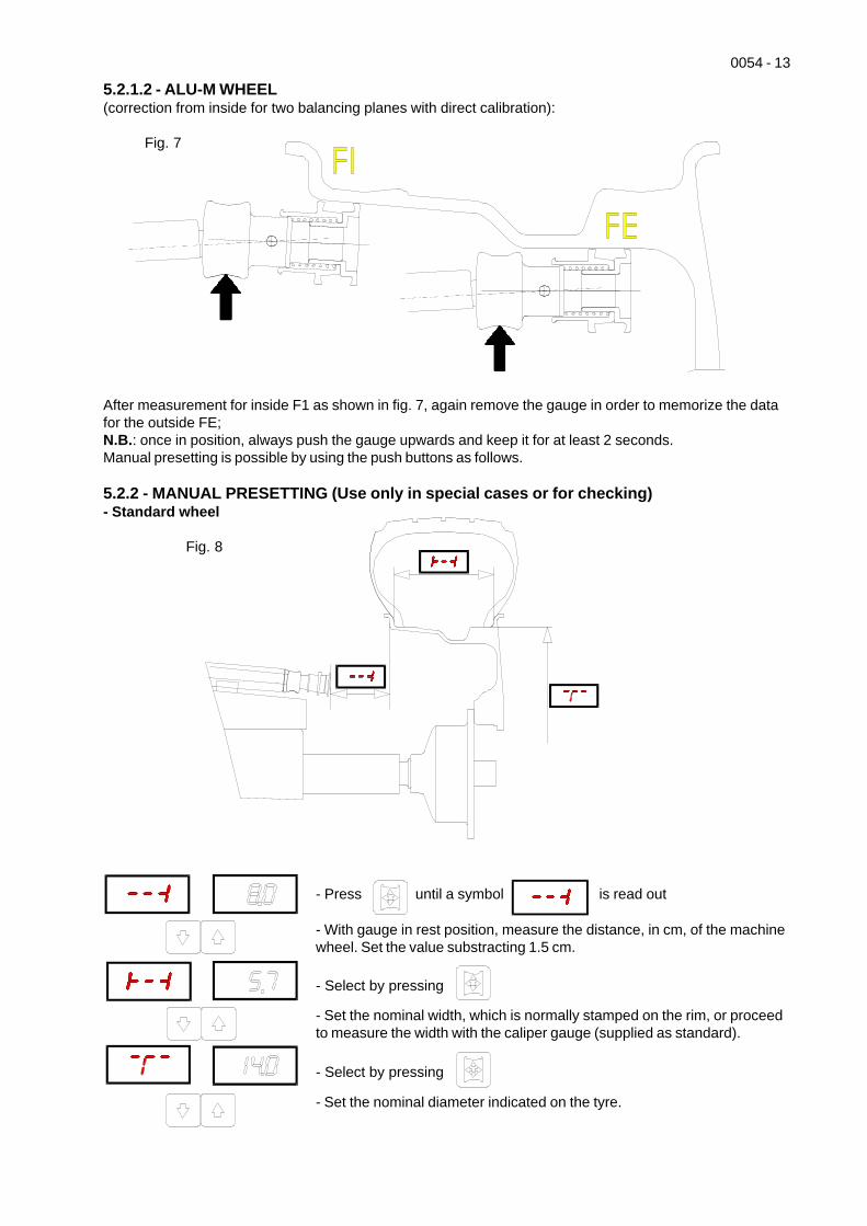
5.2.1.2 - ALU-M WHEEL(correction from inside for two balancing planes with direct calibration):
Fig. 7
After measurement for inside F1 as shown in fig. 7, again remove the gauge in order to memorize the datafor the outside FE;N.B.: once in position, always push the gauge upwards and keep it for at least 2 seconds.Manual presetting is possible by using the push buttons as follows.
5.2.2 - MANUAL PRESETTING (Use only in special cases or for checking)- Standard wheel
Fig. 8
- Press until a symbol is read out
- With gauge in rest position, measure the distance, in cm, of the machinewheel. Set the value substracting 1.5 cm.
- Select by pressing
- Set the nominal width, which is normally stamped on the rim, or proceedto measure the width with the caliper gauge (supplied as standard).
- Select by pressing
- Set the nominal diameter indicated on the tyre.
14 - 0054
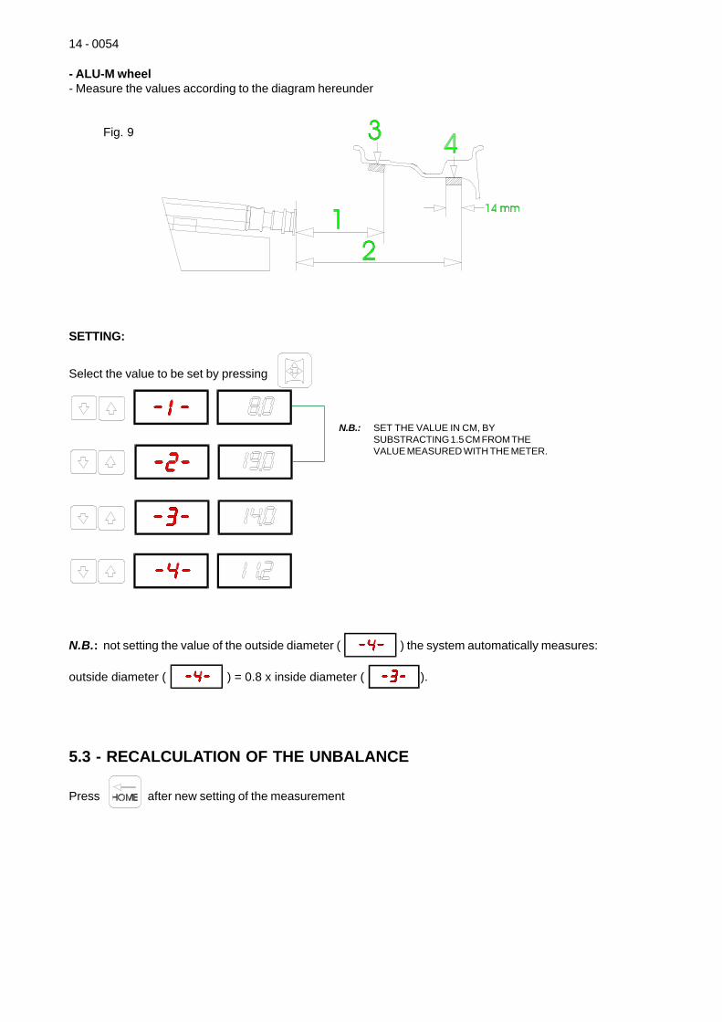
- ALU-M wheel- Measure the values according to the diagram hereunder
Fig. 9
SETTING:
Select the value to be set by pressing
N.B.: not setting the value of the outside diameter ( ) the system automatically measures:
outside diameter ( ) = 0.8 x inside diameter ( ).
5.3 - RECALCULATION OF THE UNBALANCE
Press after new setting of the measurement
N.B.: SET THE VALUE IN CM, BYSUBSTRACTING 1.5 CM FROM THEVALUE MEASURED WITH THE METER.
0054 - 15
5.4 - RESULT OF MEASUREMENT
Fig. 10Inside correction Outside correction
After performing a balancing spin, the amounts of unbalance are shown on the digital readouts.Digital readouts with LED's 3- 4 lit up indicate the correct angular wheel position to mount thecounterweights (12 o'clock position). In the event of acoustic indicator enabled (see par. 4.6.1) a "beep"indicate the correct correction position.
If the unbalance is less than the threshold selected, is displayed instead of the unbalance. With
it is possible to read the values below the threshold chosen gram by gram.
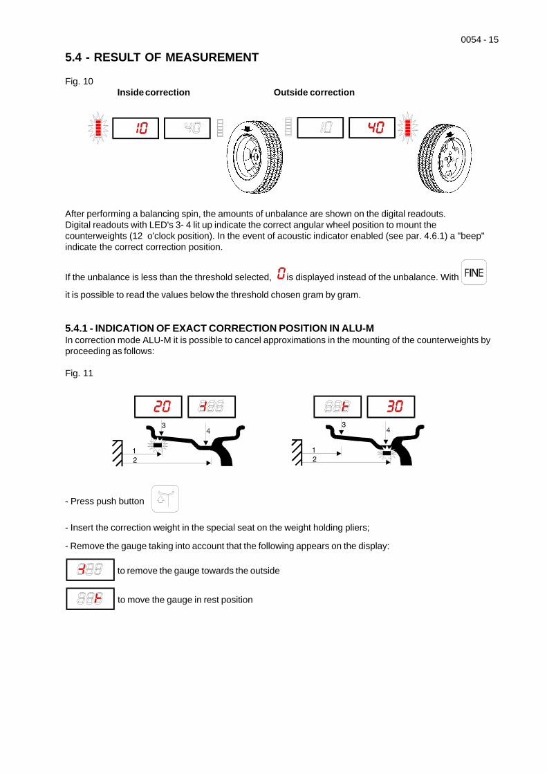
5.4.1 - INDICATION OF EXACT CORRECTION POSITION IN ALU-MIn correction mode ALU-M it is possible to cancel approximations in the mounting of the counterweights byproceeding as follows:
Fig. 11
- Press push button
- Insert the correction weight in the special seat on the weight holding pliers;
- Remove the gauge taking into account that the following appears on the display:
to remove the gauge towards the outside
to move the gauge in rest position
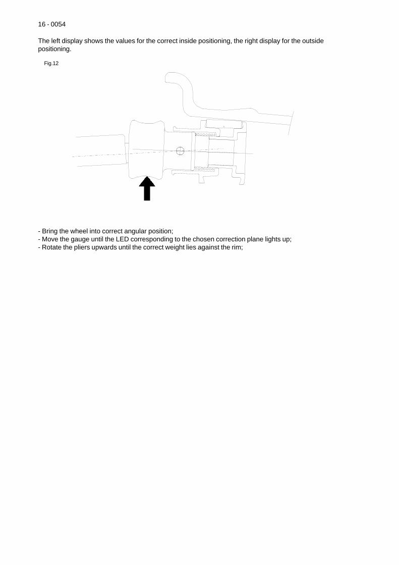
16 - 0054
The left display shows the values for the correct inside positioning, the right display for the outsidepositioning.
Fig.12
- Bring the wheel into correct angular position;- Move the gauge until the LED corresponding to the chosen correction plane lights up;- Rotate the pliers upwards until the correct weight lies against the rim;
0054 - 17
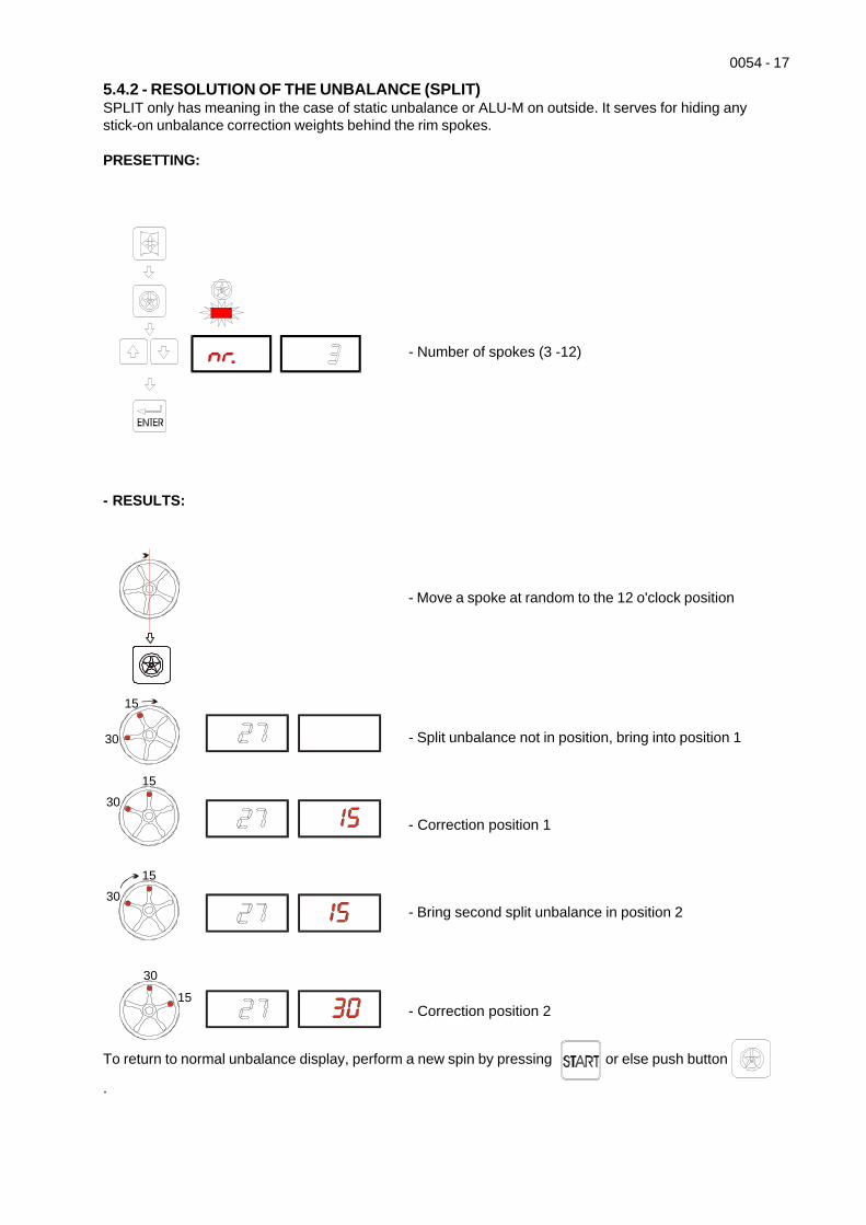
5.4.2 - RESOLUTION OF THE UNBALANCE (SPLIT)SPLIT only has meaning in the case of static unbalance or ALU-M on outside. It serves for hiding anystick-on unbalance correction weights behind the rim spokes.
PRESETTING:
- Number of spokes (3 -12)
- RESULTS:
To return to normal unbalance display, perform a new spin by pressing or else push button
.
15
30
15
15
30
30
1530
- Move a spoke at random to the 12 o'clock position
- Split unbalance not in position, bring into position 1
- Correction position 1
- Bring second split unbalance in position 2
- Correction position 2
18 - 0054
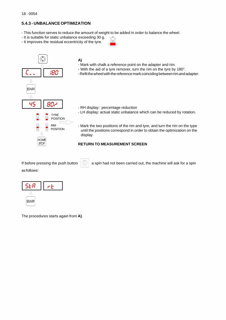
5.4.3 - UNBALANCE OPTIMIZATION
- This function serves to reduce the amount of weight to be added in order to balance the wheel.- It is suitable for static unbalance exceeding 30 g.- It improves the residual eccentricity of the tyre.
A)- Mark with chalk a reference point on the adapter and rim.- With the aid of a tyre remover, turn the rim on the tyre by 180°.- Refit the wheel with the reference mark coinciding between rim and adapter.
- RH display: percentage reduction- LH display: actual static unbalance which can be reduced by rotation.
- Mark the two positions of the rim and tyre, and turn the rim on the typeuntil the positions correspond in order to obtain the optimization on thedisplay.
RETURN TO MEASUREMENT SCREEN
If before pressing the push button a spin had not been carried out, the machine will ask for a spin
as follows:
The procedures starts again from A).
TYREPOSITION
RIMPOSITION
0054 - 19
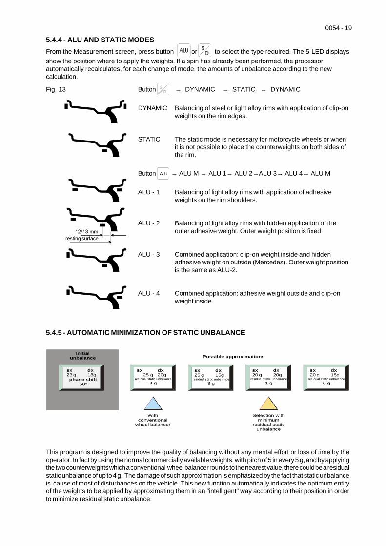
5.4.4 - ALU AND STATIC MODESFrom the Measurement screen, press button or to select the type required. The 5-LED displaysshow the position where to apply the weights. If a spin has already been performed, the processorautomatically recalculates, for each change of mode, the amounts of unbalance according to the newcalculation.
Fig. 13 Button → DYNAMIC → STATIC → DYNAMIC
DYNAMIC Balancing of steel or light alloy rims with application of clip-onweights on the rim edges.
STATIC The static mode is necessary for motorcycle wheels or whenit is not possible to place the counterweights on both sides ofthe rim.
Button ALU → ALU M → ALU 1→ ALU 2→ALU 3→ ALU 4→ ALU M
ALU - 1 Balancing of light alloy rims with application of adhesiveweights on the rim shoulders.
ALU - 2 Balancing of light alloy rims with hidden application of theouter adhesive weight. Outer weight position is fixed.
ALU - 3 Combined application: clip-on weight inside and hiddenadhesive weight on outside (Mercedes). Outer weight positionis the same as ALU-2.
ALU - 4 Combined application: adhesive weight outside and clip-onweight inside.
5.4.5 - AUTOMATIC MINIMIZATION OF STATIC UNBALANCE
This program is designed to improve the quality of balancing without any mental effort or loss of time by theoperator. In fact by using the normal commercially available weights, with pitch of 5 in every 5 g, and by applyingthe two counterweights which a conventional wheel balancer rounds to the nearest value, there could be a residualstatic unbalance of up to 4 g. The damage of such approximation is emphasized by the fact that static unbalanceis cause of most of disturbances on the vehicle. This new function automatically indicates the optimum entityof the weights to be applied by approximating them in an "intelligent" way according to their position in orderto minimize residual static unbalance.
resting surface
sx dx
phase shift23 g 18g
50°
sx dx 25 g 20g
4 gresidual static unbalance
With conventional
wheel balancer
Selection with minimum
residual static unbalance
Initial unbalance Possible approximations
sx dx 25 g 15g
3 gresidual static unbalance
sx dx 20 g 20g
1 gresidual static unbalance
sx dx 20 g 15g
6 gresidual static unbalance
20 - 0054
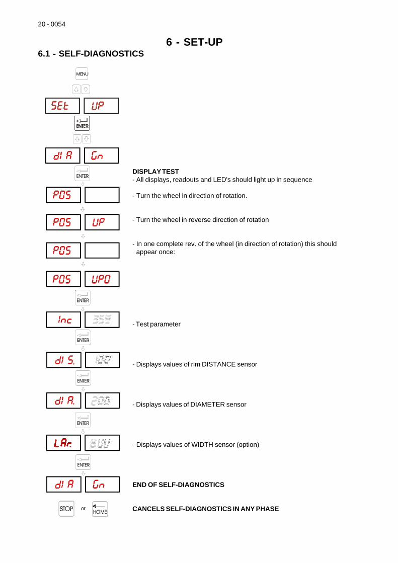
6 - SET-UP6.1 - SELF-DIAGNOSTICS
DISPLAY TEST- All displays, readouts and LED's should light up in sequence
- Turn the wheel in direction of rotation.
- Turn the wheel in reverse direction of rotation
- In one complete rev. of the wheel (in direction of rotation) this shouldappear once:
- Test parameter
- Displays values of rim DISTANCE sensor
- Displays values of DIAMETER sensor
- Displays values of WIDTH sensor (option)
END OF SELF-DIAGNOSTICS
CANCELS SELF-DIAGNOSTICS IN ANY PHASEoppureor
MENU
0054 - 21
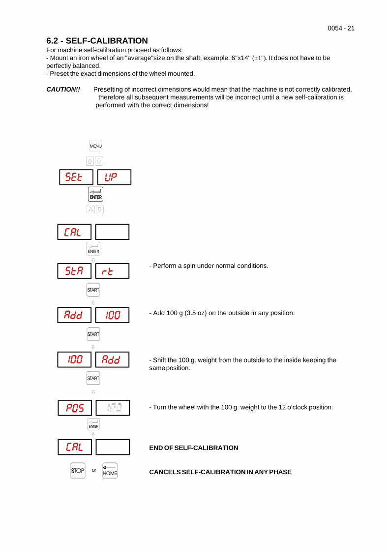
6.2 - SELF-CALIBRATIONFor machine self-calibration proceed as follows:- Mount an iron wheel of an "average"size on the shaft, example: 6''x14'' (±1''). It does not have to beperfectly balanced.- Preset the exact dimensions of the wheel mounted.
CAUTION!! Presetting of incorrect dimensions would mean that the machine is not correctly calibrated, therefore all subsequent measurements will be incorrect until a new self-calibration is performed with the correct dimensions!
- Perform a spin under normal conditions.
- Add 100 g (3.5 oz) on the outside in any position.
- Shift the 100 g. weight from the outside to the inside keeping thesame position.
- Turn the wheel with the 100 g. weight to the 12 o’clock position.
END OF SELF-CALIBRATION
CANCELS SELF-CALIBRATION IN ANY PHASEoppureor
MENU
22 - 0054
6.3 - AUTOMATIC GAUGES
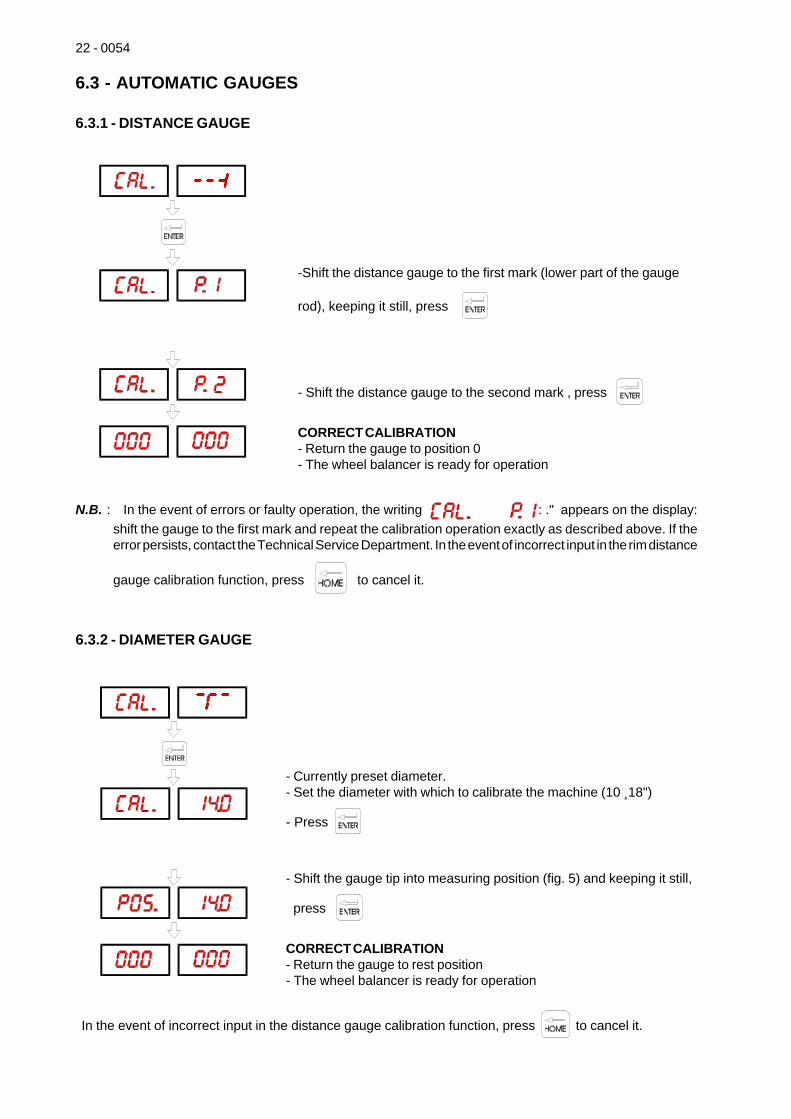
6.3.1 - DISTANCE GAUGE
-Shift the distance gauge to the first mark (lower part of the gauge
rod), keeping it still, press
- Shift the distance gauge to the second mark , press
CORRECT CALIBRATION- Return the gauge to position 0- The wheel balancer is ready for operation
N.B. : In the event of errors or faulty operation, the writing : ." appears on the display:shift the gauge to the first mark and repeat the calibration operation exactly as described above. If theerror persists, contact the Technical Service Department. In the event of incorrect input in the rim distance
gauge calibration function, press to cancel it.
6.3.2 - DIAMETER GAUGE
- Currently preset diameter.- Set the diameter with which to calibrate the machine (10 ¸18")
- Press
- Shift the gauge tip into measuring position (fig. 5) and keeping it still,
press
CORRECT CALIBRATION- Return the gauge to rest position- The wheel balancer is ready for operation
In the event of incorrect input in the distance gauge calibration function, press to cancel it.
0054 - 23
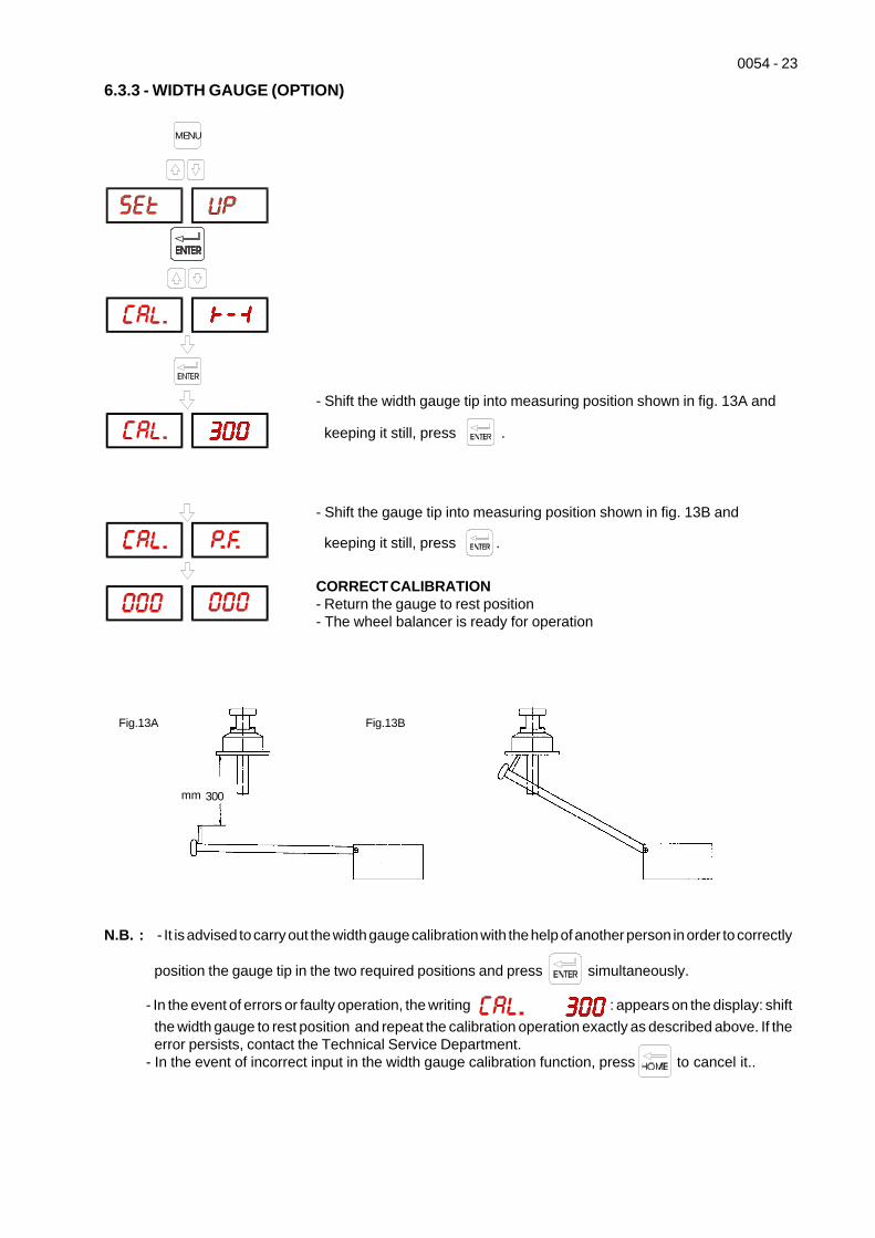
6.3.3 - WIDTH GAUGE (OPTION)
N.B. : - It is advised to carry out the width gauge calibration with the help of another person in order to correctly
position the gauge tip in the two required positions and press simultaneously.
- In the event of errors or faulty operation, the writing : appears on the display: shiftthe width gauge to rest position and repeat the calibration operation exactly as described above. If theerror persists, contact the Technical Service Department.
- In the event of incorrect input in the width gauge calibration function, press to cancel it..
Fig.13A Fig.13B
mm 235
- Shift the width gauge tip into measuring position shown in fig. 13A and
keeping it still, press .
- Shift the gauge tip into measuring position shown in fig. 13B and
keeping it still, press .
CORRECT CALIBRATION- Return the gauge to rest position- The wheel balancer is ready for operation
300
MENU
24 - 0054
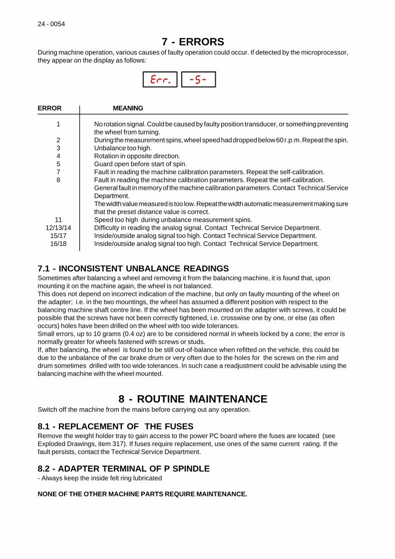
7 - ERRORSDuring machine operation, various causes of faulty operation could occur. If detected by the microprocessor,they appear on the display as follows:
ERROR MEANING
1 No rotation signal. Could be caused by faulty position transducer, or something preventingthe wheel from turning.
2 During the measurement spins, wheel speed had dropped below 60 r.p.m. Repeat the spin.3 Unbalance too high.4 Rotation in opposite direction.5 Guard open before start of spin.7 Fault in reading the machine calibration parameters. Repeat the self-calibration.8 Fault in reading the machine calibration parameters. Repeat the self-calibration.
General fault in memory of the machine calibration parameters. Contact Technical ServiceDepartment.The width value measured is too low. Repeat the width automatic measurement making surethat the preset distance value is correct.
11 Speed too high during unbalance measurement spins.12/13/14 Difficulty in reading the analog signal. Contact Technical Service Department.
15/17 Inside/outside analog signal too high. Contact Technical Service Department.16/18 Inside/outside analog signal too high. Contact Technical Service Department.
7.1 - INCONSISTENT UNBALANCE READINGSSometimes after balancing a wheel and removing it from the balancing machine, it is found that, uponmounting it on the machine again, the wheel is not balanced.This does not depend on incorrect indication of the machine, but only on faulty mounting of the wheel onthe adapter; i.e. in the two mountings, the wheel has assumed a different position with respect to thebalancing machine shaft centre line. If the wheel has been mounted on the adapter with screws, it could bepossible that the screws have not been correctly tightened, i.e. crosswise one by one, or else (as oftenoccurs) holes have been drilled on the wheel with too wide tolerances.Small errors, up to 10 grams (0.4 oz) are to be considered normal in wheels locked by a cone; the error isnormally greater for wheels fastened with screws or studs.If, after balancing, the wheel is found to be still out-of-balance when refitted on the vehicle, this could bedue to the unbalance of the car brake drum or very often due to the holes for the screws on the rim anddrum sometimes drilled with too wide tolerances. In such case a readjustment could be advisable using thebalancing machine with the wheel mounted.
8 - ROUTINE MAINTENANCESwitch off the machine from the mains before carrying out any operation.
8.1 - REPLACEMENT OF THE FUSESRemove the weight holder tray to gain access to the power PC board where the fuses are located (seeExploded Drawings, item 317). If fuses require replacement, use ones of the same current rating. If thefault persists, contact the Technical Service Department.
8.2 - ADAPTER TERMINAL OF P SPINDLE- Always keep the inside felt ring lubricated
NONE OF THE OTHER MACHINE PARTS REQUIRE MAINTENANCE.
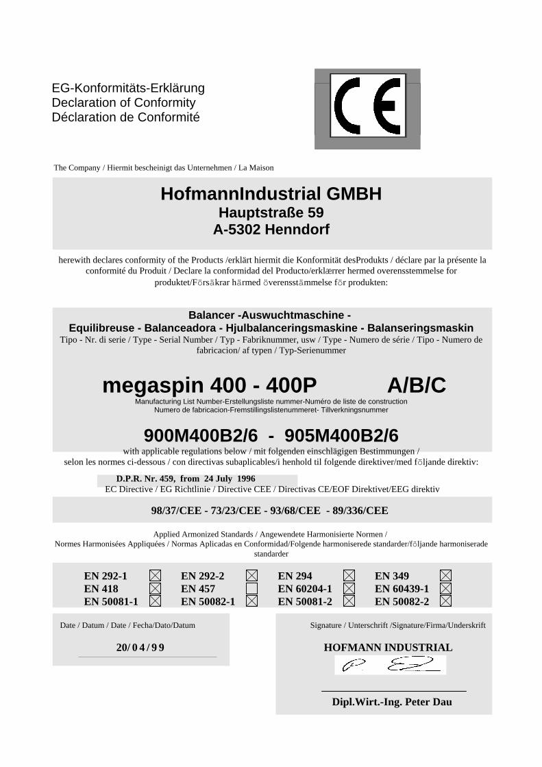
EG-Konformitäts-Erklärung Declaration of ConformityDéclaration de Conformité
The Company / Hiermit bescheinigt das Unternehmen / La Maison
HofmannIndustrial GMBHHauptstraße 59
A-5302 Henndorf
herewith declares conformity of the Products /erklärt hiermit die Konformität desProdukts / déclare par la présente laconformité du Produit / Declare la conformidad del Producto/erklærrer hermed overensstemmelse for
produktet/Försäkrar härmed överensstämmelse för produkten:
Balancer -Auswuchtmaschine - Equilibreuse - Balanceadora - Hjulbalanceringsmaskine - Balanseringsmaskin
Tipo - Nr. di serie / Type - Serial Number / Typ - Fabriknummer, usw / Type - Numero de série / Tipo - Numero defabricacion/ af typen / Typ-Serienummer
megaspin 400 - 400P A/B/CManufacturing List Number-Erstellungsliste nummer-Numéro de liste de construction
Numero de fabricacion-Fremstillingslistenummeret- Tillverkningsnummer
900M400B2/6 - 905M400B2/6 with applicable regulations below / mit folgenden einschlägigen Bestimmungen /
selon les normes ci-dessous / con directivas subaplicables/i henhold til folgende direktiver/med följande direktiv:
D.P.R. Nr. 459, from 24 July 1996 EC Directive / EG Richtlinie / Directive CEE / Directivas CE/EOF Direktivet/EEG direktiv
98/37/CEE - 73/23/CEE - 93/68/CEE - 89/336/CEE
Applied Armonized Standards / Angewendete Harmonisierte Normen / Normes Harmonisées Appliquées / Normas Aplicadas en Conformidad/Folgende harmoniserede standarder/följande harmoniserade
standarder
EN 292-1 EN 292-2 EN 294 EN 349EN 418 EN 457 EN 60204-1 EN 60439-1EN 50081-1 EN 50082-1 EN 50081-2 EN 50082-2
Date / Datum / Date / Fecha/Dato/Datum Signature / Unterschrift /Signature/Firma/Underskrift
20/ 0 4 / 9 9 HOFMANN INDUSTRIAL
Dipl.Wirt.-Ing. Peter Dau