Embed Size (px)
Citation preview

7/24/2019 Welding Metallurgy Part 2
http://slidepdf.com/reader/full/welding-metallurgy-part-2 1/28

7/24/2019 Welding Metallurgy Part 2
http://slidepdf.com/reader/full/welding-metallurgy-part-2 2/28
2
Topics:
Objectives Introduction
Gas-metal reactions
Fluxes
Fluid flow in arcs Fluid flow in weld pools
Metal evaporation
Rate of metal transfer
A schematic representation of a welding (arc) process
Chemical reactions and metal flow in welding
Dr. O ğ uzhan Y ı lmaz
Welding Technology Welding Technology

7/24/2019 Welding Metallurgy Part 2
http://slidepdf.com/reader/full/welding-metallurgy-part-2 3/28
3
Objectives
This chapter provides an information on chemical reactions occurring
during welding. This is, for example, the reactions of hydrogen and slag
which significantly affect the microstructure of the weld, and hence theproperties of the weld.
Students are required to understand the effect of chemical reactions andthe fluid flow on the shape of the resultant between the weld and gases
(oxygen, nitrogen and hydrogen) and weld pool.
Dr. O ğ uzhan Y ı lmaz
Welding Technology Welding Technology

7/24/2019 Welding Metallurgy Part 2
http://slidepdf.com/reader/full/welding-metallurgy-part-2 4/284
Introduction
During welding, nitrogen, oxygen and hydrogen can dissolve in the hot weld
metal, which in turn significantly affect the soundness of the resultant weld.
Dr. O ğ uzhan Y ı lmaz
Welding Technology Welding Technology

7/24/2019 Welding Metallurgy Part 2
http://slidepdf.com/reader/full/welding-metallurgy-part-2 5/28
5
Introduction
There are various techniques used to protect
weld pool during fusion welding, each of which
provides different degree of weld metal protection.
Dr. O ğ uzhan Y ı lmaz
Welding Technology Welding Technology

7/24/2019 Welding Metallurgy Part 2
http://slidepdf.com/reader/full/welding-metallurgy-part-2 6/28
6
Gas-metal reaction
The gas-metal reactions take place at the interface between the gas
phase and the liquid metal, including the dissolution of nitrogen, oxygen
and hydrogen in the liquid metal and the evolution of CO.
• In arc welding, portions of N2, O2
and H2 can dissociate (or even
ionize) under the high temperature of
the arc plasma. These atomic N, Oand H can dissolve in the molten
metals.
½ N2 (g) N
½ O2 (g) O
½ H2 (g)
H
where N, O and H aredissolved nitrogen, oxygen
and hydrogen in liquid
metal.Equilibrium concentration
of hydrogen as a function of weld pool locati
Dr. O ğ uzhan Y ı lmaz
Welding Technology Welding Technology

7/24/2019 Welding Metallurgy Part 2
http://slidepdf.com/reader/full/welding-metallurgy-part-2 7/28
7
Oxygen
SOURCE is air, excess
oxygen, in oxyfuel welding, or
O,CO in shielding gas, or
decomposition of oxide in fluxand from slag-metal arc
reaction.
EFFECT oxygen can oxidize
carbon and alloyingelements, depressing
hardenability, producing
inclusions Poor
mechanical properties Effect of oxygen equivalent (OE) on ductility of titaniumwelds
Example: in oxyacetylene welding
Excess oxygenlow carbon level
Excess aceytlene high carbon level(carburazing flame)
Poor mechanical propertiesSolution: use oxygen:acetylene ratio close to 1
Dr. O ğ uzhan Y ı lmaz
Welding Technology Welding Technology

7/24/2019 Welding Metallurgy Part 2
http://slidepdf.com/reader/full/welding-metallurgy-part-2 8/28
8
Excessive weld metal oxygen
Excessive weld metal oxygen leads to
oxide inclusions lower weld metal
mechanical properties by acting as
fracture initiation sites.
Oxygen can also react with carbon to
form CO gas during solidification
Result: gas porosity.
oxygen
toughness
Fracture initiation at an inclusion in
flux-core arc weld of high strength
low-alloy steel.
Wormhole porosity in weld metal
Dr. O ğ uzhan Y ı lmaz
Welding Technology Welding Technology

7/24/2019 Welding Metallurgy Part 2
http://slidepdf.com/reader/full/welding-metallurgy-part-2 9/28
9
Hydrogen in steel welds
SOURCE
• Combustion products in oxyfuel welding
• Decomposition products of cellulose-type electrode
• Moisture and grease on the surface of theworkpiece/electrode
• Moisture in the flux, electrode covering, shielding
gas.
Hydrogen reduction methods
• Avoid hydrogen containing shielding gas, cellulose-
type electrode
• Dry the electrode covering to remove moisture• Clean the workpiece and filler wire to remove grease
• Using CaF2 (calcium fluoride) containing flux or
electrode covering.
Dr. O ğ uzhan Y ı lmaz
Welding Technology Welding Technology
7/24/2019 Welding Metallurgy Part 2
http://slidepdf.com/reader/full/welding-metallurgy-part-2 10/28
10
Fluxes
The solubility of oxygen and the formation of metallic compounds inweld metal means that protection of the molten pool is necessary. Thiscan be achieved by;
1. Using flux2. Providing an inert- or semi-inert gas shield
3. Welding in a vacuum chamber
In welding, the intensity of reaction between metal and atmospheric gases isgreatest when the metal in molten, but below this temperature aprogressive combination of metal and oxygen is taking place
A flux or chemical solvent is used to remove the oxide layer.
To use a proper type of flux which may differ for welding process, helps tocontrol weld metal composition as well as to protect the weld from theair.
Dr. O ğ uzhan Y ı lmaz
Welding Technology Welding Technology

7/24/2019 Welding Metallurgy Part 2
http://slidepdf.com/reader/full/welding-metallurgy-part-2 11/28
11
Electrochemical reactions
Anodic oxidation reactions
For electrode positive polarity,
these reactions occur at the
electrode tip-slag interface or the
weld pool-slag interface in the
electrode negative polarity.
Losses of alloying elements
Pickup of oxygen at anode
Cathodic reduction reactions
For electrode positive polarity,
these reactions occur at the weldpool-slag interface or the electrod
tip-slag interface in the electrode
negative polarity.
Reduction of metallic cations from
the slag, removal oxygen from the
metalDr. O ğ uzhan Y ı lmaz
Welding Technology Welding Technology

7/24/2019 Welding Metallurgy Part 2
http://slidepdf.com/reader/full/welding-metallurgy-part-2 12/28
12
Welding Technology Welding Technology
Electrochemical reactions
Anode Oxygen pickup
Cathode oxygen removal
Electrode positive polarityOxygen pickup at electrode tip-slag interface
Oxygen removal at weld-pool slag interface
Electrode negative polarity
Oxygen pickup at weld pool-slag interface
Oxygen removal at electrode tip-slag interface
Oxygen contents of the welding wire, melted electrode tips
and detached droplets for both electrode positive and
electrode negative polarities.Dr. O ğ uzhan Y ı lmaz
W ldi T h lW ldi T h l
7/24/2019 Welding Metallurgy Part 2
http://slidepdf.com/reader/full/welding-metallurgy-part-2 13/28
13
Fluid flow in arcs
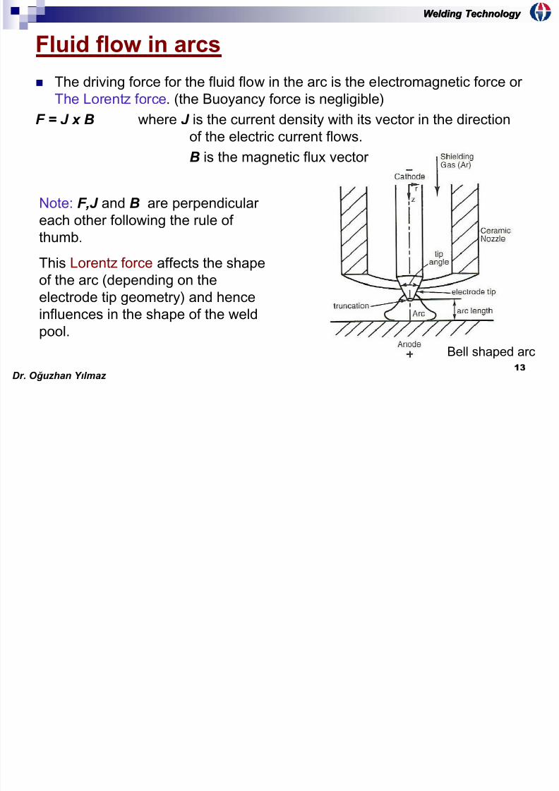
The driving force for the fluid flow in the arc is the electromagnetic force or
The Lorentz force. (the Buoyancy force is negligible)
F = J x B where J is the current density with its vector in the direction
of the electric current flows.B is the magnetic flux vector
Note: F,J and B are perpendiculareach other following the rule of
thumb.
This Lorentz force affects the shapeof the arc (depending on the
electrode tip geometry) and hence
influences in the shape of the weld
pool.Bell shaped arc
Dr. O ğ uzhan Y ı lmaz
Welding Technology Welding Technology
W ldi T h lW ldi T h l
7/24/2019 Welding Metallurgy Part 2
http://slidepdf.com/reader/full/welding-metallurgy-part-2 14/28
14
Arcs shape
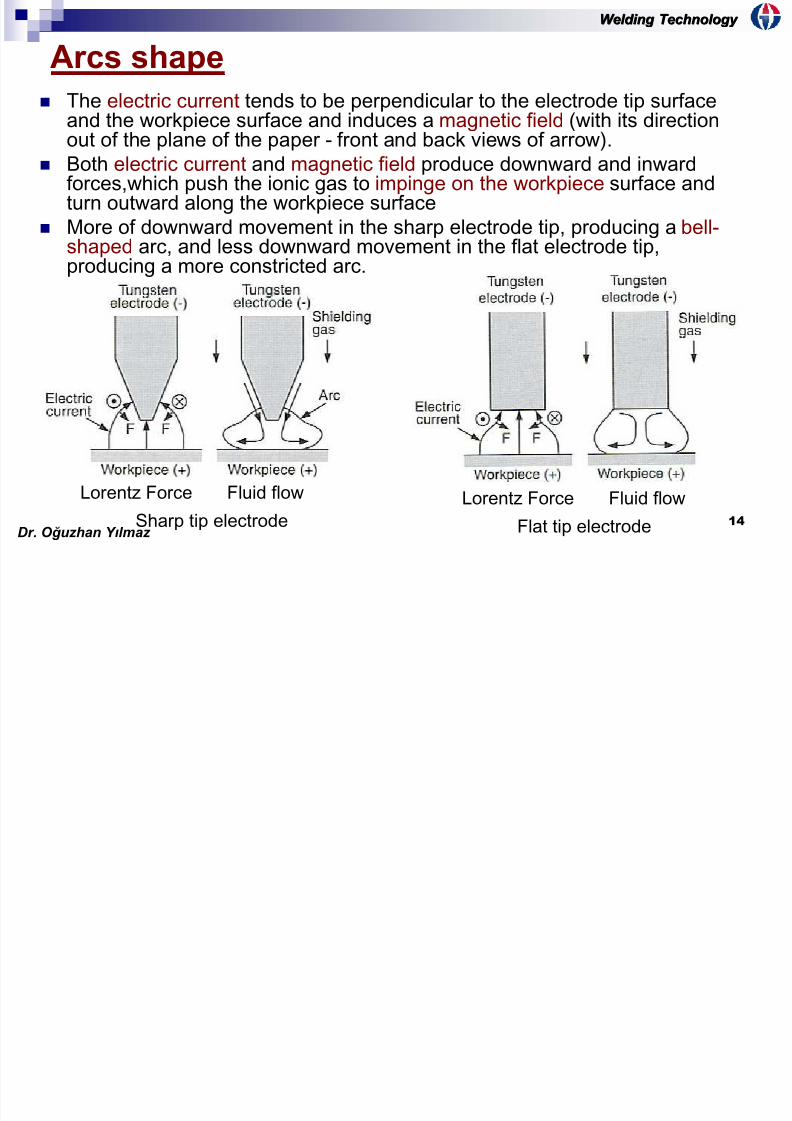
The electric current tends to be perpendicular to the electrode tip surfaceand the workpiece surface and induces a magnetic field (with its directionout of the plane of the paper - front and back views of arrow).
Both electric current and magnetic field produce downward and inward
forces,which push the ionic gas to impinge on the workpiece surface andturn outward along the workpiece surface
More of downward movement in the sharp electrode tip, producing a bell-shaped arc, and less downward movement in the flat electrode tip,producing a more constricted arc.
Lorentz Force Fluid flow
Sharp tip electrode
Lorentz Force Fluid flow
Flat tip electrodeDr. O ğ uzhan Y ı lmaz
Welding Technology Welding Technology
Welding TechnologyWelding Technology

7/24/2019 Welding Metallurgy Part 2
http://slidepdf.com/reader/full/welding-metallurgy-part-2 15/28
15
Velocity and temperature field
Downward and inward momentums due to electric current and magneticfield cause different fluid flow in sharp and flat electrode tips.
Sharp electrode tip Flat electrode tip
Note: Downward momentum is stronger in the sharp electrode tip than in the
flat electrode tip.Dr. O ğ uzhan Y ı lmaz
Welding Technology Welding Technology
Welding TechnologyWelding Technology

7/24/2019 Welding Metallurgy Part 2
http://slidepdf.com/reader/full/welding-metallurgy-part-2 16/28
16
Fluid flows in weld pools
Driving forces for the fluid flow in the weld pool include
Buoyancy force
Lorentz force
Shear stress induced by surface tension gradient at the weld pool surface
Shear stress acting on the pool surface by the arc plasma.
Arc pressure (only small influence).
Dr. O ğ uzhan Y ı lmaz
Welding Technology Welding Technology
Welding TechnologyWelding Technology

7/24/2019 Welding Metallurgy Part 2
http://slidepdf.com/reader/full/welding-metallurgy-part-2 17/28
17
Driving forces for weld pool convection
Buoyancy force
Cooler liquid metal at point b is heavier than
point a causing gravity sinks along the pool
boundary and rises along the pool axis.
Lorentz Force (liquid metal movesdownward)
Electric current and magnetic field cause the
liquid metal flows downward along the weld
pool axis and rises along the weld poolboundary.
Surface Tension force
Warmer liquid metal having a lower surface
tension (γ) at point b pulls out the liquid metalin the middle (point a) along the pool surface.
Arc Shear stress
High speed outward movement of plasma arc
lead to outward shear stress, hence causing
metal flowing from the centre to the edge of
the pool.
Buoyancy Force
Lorentz ForceCarry the heat from
top to bottom
Surface Tension Force
Arc shear stressPlasma jet
Dr. O ğ uzhan Y ı lmaz
Welding Technology Welding Technology
Welding TechnologyWelding Technology
7/24/2019 Welding Metallurgy Part 2
http://slidepdf.com/reader/full/welding-metallurgy-part-2 18/28
18
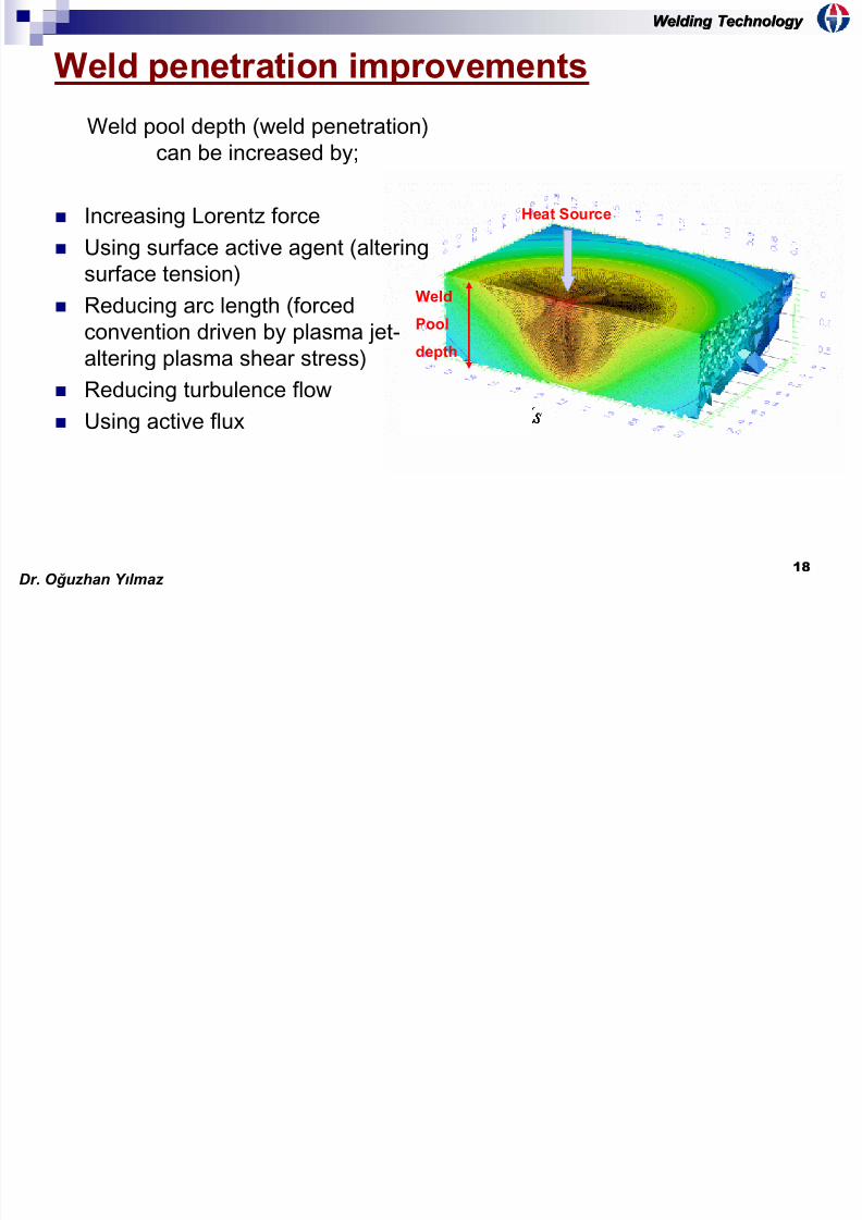
Weld penetration improvements
Weld pool depth (weld penetration)
can be increased by;
Increasing Lorentz force
Using surface active agent (altering
surface tension)
Reducing arc length (forcedconvention driven by plasma jet-
altering plasma shear stress)
Reducing turbulence flow
Using active flux
Weld
Pool
depth
Heat Source
Dr. O ğ uzhan Y ı lmaz
Welding Technology Welding Technology
Welding TechnologyWelding Technology

7/24/2019 Welding Metallurgy Part 2
http://slidepdf.com/reader/full/welding-metallurgy-part-2 19/28
19
Weld penetration improvement
Increasing Lorentz Force
The Lorentz force makes the weld
pool much deeper as compared tothe Buoyancy force.
The liquid metal pushed downward
by the Lorentz force carries heat
from the heat source (at the middle
top surface) to the pool bottom and
causes a deep penetration.
Lorentz force
Buoyancy Force
Dr. O ğ uzhan Y ı lmaz
Welding Technology Welding Technology
Welding Technology Welding Technology

7/24/2019 Welding Metallurgy Part 2
http://slidepdf.com/reader/full/welding-metallurgy-part-2 20/28
20
Weld pool depth improvement
Reducing arc lenght (forced convection driven by plasma jet)
Long arc length outweights both Lorentz force and the surface tension
Arc length vs voltage and heat
Stationary gas-tungsten arc weld in a mild
steel made with a 2-mm and 8-mm arc lenght
Dr. O ğ uzhan Y ı lmaz
e d g ec o ogyg gy
Welding Technology Welding Technology
7/24/2019 Welding Metallurgy Part 2
http://slidepdf.com/reader/full/welding-metallurgy-part-2 21/28
21
Weld penetration improvement
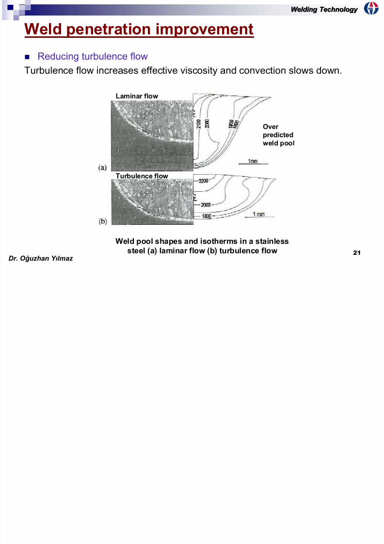
Reducing turbulence flow
Turbulence flow increases effective viscosity and convection slows down.
Laminar flow
Turbulence flow
Over
predicted
weld pool
Weld pool shapes and isotherms in a stainless
steel (a) laminar flow (b) turbulence flowDr. O ğ uzhan Y ı lmaz
g gyg gy
Welding Technology Welding Technology

7/24/2019 Welding Metallurgy Part 2
http://slidepdf.com/reader/full/welding-metallurgy-part-2 22/28
22
Metal evaporation
Loss of alloying elements
High welding temperature causes
evaporation of metals in the weld
pool especially alloying elements affecting mechanical properties
Vapour pressure
Tendency to
evaporate
Mg loss in a layer weld of Al-Mg alloy
Ex: Mg loss in aluminium weld results in a substantial
reduction of tensile properties due to decreased solid solution
strengthening of lower amount of Mg.
Dr. O ğ uzhan Y ı lmaz
g gy
Welding Technology Welding Technology
7/24/2019 Welding Metallurgy Part 2
http://slidepdf.com/reader/full/welding-metallurgy-part-2 23/28
23
Metal evaporation
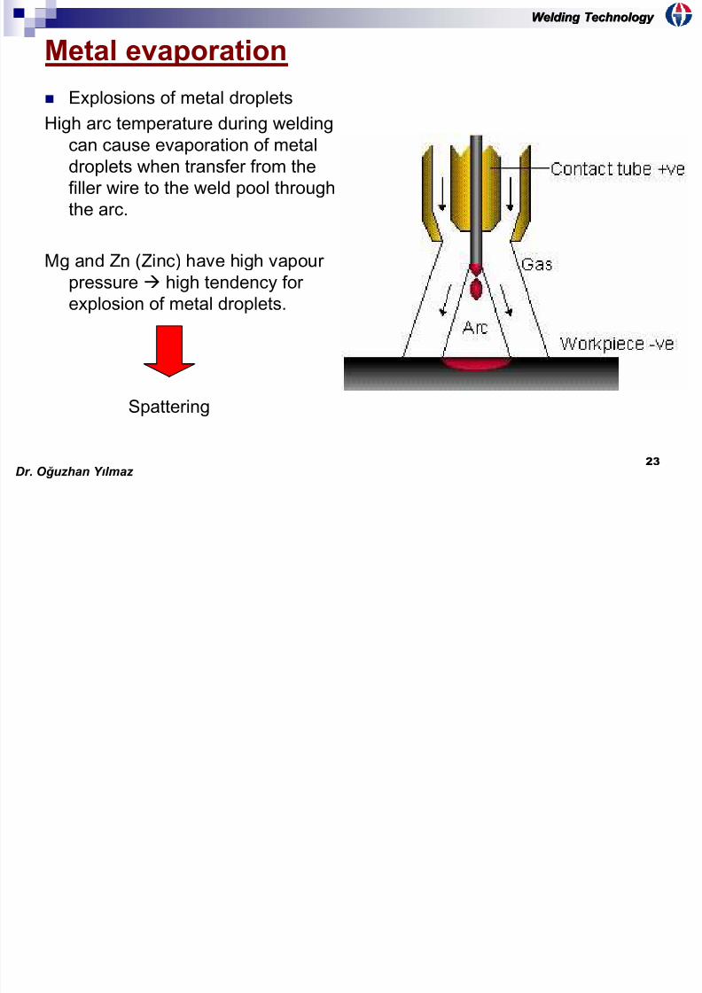
Explosions of metal droplets
High arc temperature during welding
can cause evaporation of metal
droplets when transfer from thefiller wire to the weld pool through
the arc.
Mg and Zn (Zinc) have high vapourpressure high tendency for
explosion of metal droplets.
Spattering
Dr. O ğ uzhan Y ı lmaz
Welding Technology Welding Technology
7/24/2019 Welding Metallurgy Part 2
http://slidepdf.com/reader/full/welding-metallurgy-part-2 24/28
24
Metal transfer
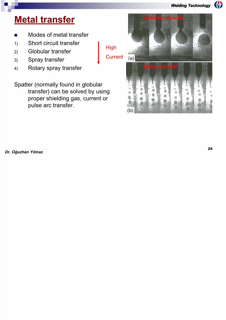
Modes of metal transfer
1) Short circuit transfer
2) Globular transfer
3) Spray transfer
4) Rotary spray transfer
Spatter (normally found in globulartransfer) can be solved by using
proper shielding gas, current or
pulse arc transfer.
High
Current
Dr. O ğ uzhan Y ı lmaz
Welding Technology Welding Technology

7/24/2019 Welding Metallurgy Part 2
http://slidepdf.com/reader/full/welding-metallurgy-part-2 25/28
25
Effect of shielding gases on metal transfer
CO2 and N2 are normally give globular transfer, greater instability in the
arc and chemical reaction between the gas and superheated metal
droplets
considerable spatters. This can be changed to spray transferby treatment of the wire surface.
Mixtures of Ar and He are used in welding non-ferrous (especially Al, Cu)
Higher percentage of He in the mixture is used for welding thick sections
due to higher temperature of the plasma obtained.
Ar Ionisation potential= 15.8volt Plasma temp= 15.8 x 1000K
He Ionisation potential= 24.6volt Plasma temp= 24.6 x 1000K
Dr. O ğ uzhan Y ı lmaz
Welding Technology Welding Technology

7/24/2019 Welding Metallurgy Part 2
http://slidepdf.com/reader/full/welding-metallurgy-part-2 26/28
26
Volume of metal deposited
The volume of metal deposited per unit time can be determined by
V d = A d x v d
Where V d is the volume of metal deposited per unit time
A d is deposited metal cross-section (filler)
v d is welding process travel speed.
The volume of wire electrode per unit time can be determined by
V w = Aw x vw
Where V w is the volume of the electrode wire per unit time
Aw is cross-section area of the electrode wire
vw is wire linear feed rate.
Dr. O ğ uzhan Y ı lmaz
Welding Technology Welding Technology

7/24/2019 Welding Metallurgy Part 2
http://slidepdf.com/reader/full/welding-metallurgy-part-2 27/28
27
Total cross-section area
of melted metal
Const.= 3.33 x 10⁻² for I = amp
v (speed) = mm/sec
Nugget Area = mm2
If the current and welding
speed are known, the
nugget area can be
estimated.
The nugget area is inversely related to the cooling rate, giving a good indicator
of metallurgical structure.
Heat Input Nugget Area Cooling rate
Coarse microstructureDr. O ğ uzhan Y ı lmaz
Welding Technology Welding Technology

7/24/2019 Welding Metallurgy Part 2
http://slidepdf.com/reader/full/welding-metallurgy-part-2 28/28
28
Prediction of weld penetration
The weld penetrarion can be predicted
through the expression (Jackson
definition) below:
Where P is weld penetration (in)
I is current
v is travel speed (in/sec) E is arc voltage (volts)
k is constant between 0.0010-
0.0019depending on the process
Current
Weld penetration
Dr. O ğ uzhan Y ı lmaz


![Welding Metallurgy[1]](https://img.dokumen.tips/doc/110x75/55cf8e70550346703b9232af/welding-metallurgy1.jpg)