Embed Size (px)
Citation preview

1
WELDING GUIDEFOR HENSLEY
WELD-ON NOSES&
NOSE REBUILDS
MAY 2009
2
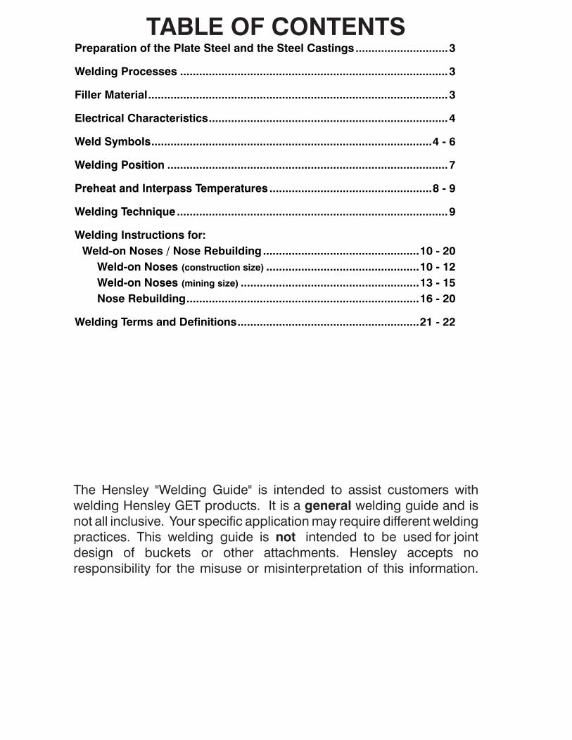
TABLE OF CONTENTSPreparation of the Plate Steel and the Steel Castings .............................3
Welding Processes ....................................................................................3
Filler Material ..............................................................................................3
Electrical Characteristics ...........................................................................4
Weld Symbols ........................................................................................4 - 6
Welding Position ........................................................................................7
Preheat and Interpass Temperatures ...................................................8 - 9
Welding Technique .....................................................................................9
Welding Instructions for: Weld-on Noses / Nose Rebuilding .................................................10 - 20 Weld-on Noses (construction size) ................................................10 - 12 Weld-on Noses (mining size) ........................................................13 - 15 Nose Rebuilding .........................................................................16 - 20
Welding Terms and Definitions .........................................................21 - 22
The Hensley "Welding Guide" is intended to assist customers with welding Hensley GET products. It is a general welding guide and is not all inclusive. Your specific application may require different welding practices. This welding guide is not intended to be used for joint design of buckets or other attachments. Hensley accepts no responsibility for the misuse or misinterpretation of this information.
3
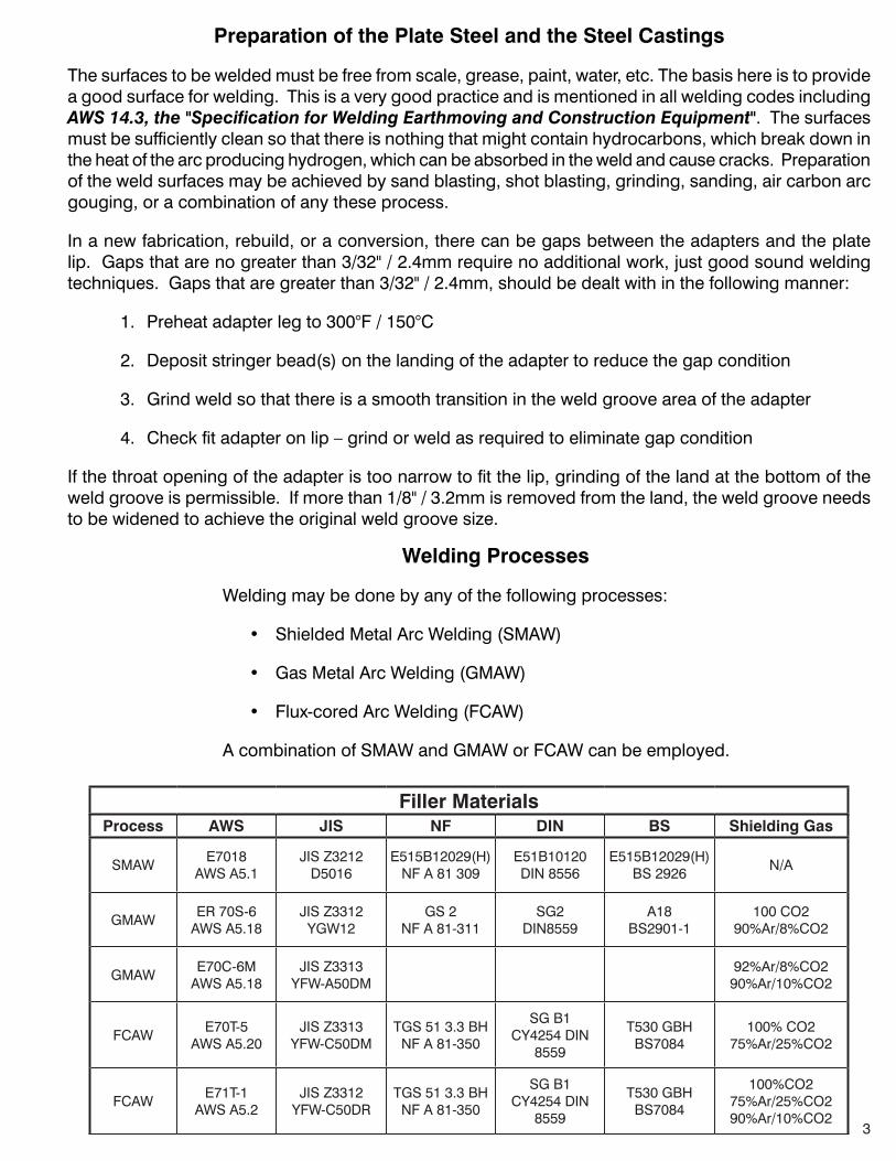
Preparation of the Plate Steel and the Steel Castings
The surfaces to be welded must be free from scale, grease, paint, water, etc. The basis here is to provide a good surface for welding. This is a very good practice and is mentioned in all welding codes including AWS 14.3, the "Specification for Welding Earthmoving and Construction Equipment". The surfaces must be sufficiently clean so that there is nothing that might contain hydrocarbons, which break down in the heat of the arc producing hydrogen, which can be absorbed in the weld and cause cracks. Preparation of the weld surfaces may be achieved by sand blasting, shot blasting, grinding, sanding, air carbon arc gouging, or a combination of any these process.
In a new fabrication, rebuild, or a conversion, there can be gaps between the adapters and the plate lip. Gaps that are no greater than 3/32" / 2.4mm require no additional work, just good sound welding techniques. Gaps that are greater than 3/32" / 2.4mm, should be dealt with in the following manner:
1. Preheat adapter leg to 300°F / 150°C
2. Deposit stringer bead(s) on the landing of the adapter to reduce the gap condition
3. Grind weld so that there is a smooth transition in the weld groove area of the adapter
4. Check fit adapter on lip – grind or weld as required to eliminate gap condition
If the throat opening of the adapter is too narrow to fit the lip, grinding of the land at the bottom of the weld groove is permissible. If more than 1/8" / 3.2mm is removed from the land, the weld groove needs to be widened to achieve the original weld groove size.
Welding Processes
Welding may be done by any of the following processes:
• ShieldedMetalArcWelding(SMAW)
• GasMetalArcWelding(GMAW)
• Flux-coredArcWelding(FCAW)
AcombinationofSMAWandGMAWorFCAWcanbeemployed.
Filler MaterialsProcess AWS JIS NF DIN BS Shielding Gas
SMAWE7018 AWSA5.1
JISZ3212 D5016
E515B12029(H) NFA81309
E51B10120 DIN 8556
E515B12029(H) BS2926
N/A
GMAWER70S-6 AWSA5.18
JISZ3312 YGW12
GS2 NFA81-311
SG2 DIN8559
A18 BS2901-1
100 CO2 90%Ar/8%CO2
GMAWE70C-6M AWSA5.18
JISZ3313 YFW-A50DM
92%Ar/8%CO2 90%Ar/10%CO2
FCAWE70T-5
AWSA5.20JISZ3313 YFW-C50DM
TGS513.3BH NFA81-350
SGB1 CY4254 DIN
8559
T530 GBH BS7084
100% CO2 75%Ar/25%CO2
FCAWE71T-1 AWSA5.2
JISZ3312 YFW-C50DR
TGS513.3BH NFA81-350
SGB1 CY4254 DIN
8559
T530 GBH BS7084
100%CO2 75%Ar/25%CO2 90%Ar/10%CO2

4
Electrical Characteristics
A. Polarity
Allweldingshallbedoneusingdirectcurrentelectrodepositive(DCEP)
B. Current and Voltage Ranges
SMAWElectrode Diameter Amperes
2.4mm / 3/32 in. 65 to 120
3.2mm / 1/8 in. 80 to 160
4.0mm / 5/32 in. 115 to 220
4.8mm / 3/16 in. 140 to 300
GMAW and FCAWElectrode Diameter Voltage Amperes
1.2mm / 0.045 in 22 to 30 220 to 320
1.4 mm / 0.052 25 to 30 250 to 325
1.6mm / 1/16 in. 25 to 35 250 to 360
2.4mm / 3/32 in 28 to 35 350 to 450
Welding Symbols
Weld symbols are used as a type of shorthand to indicate the type of weld, its size and other processing and finishing information. The following section will introduce you to the most common symbols you may encounter, while using our product, and their meaning. The complete set of symbols is given in a standard published by American National Standards Institute (ANSI)andtheAmerican Welding Society (AWS):ANSI/AWS A2.4, Symbols for Welding and Nondestructive Testing.
Welding Symbol Structure
The horizontal line , called the reference line, is the anchor to which all the other welding symbols are tied.Theinstructionsformakingtheweldarestrungalongthereferenceline.Anarrowconnectsthereference line to the joint that is to be welded. The example above has the arrow growing out of the right end of the reference line and heading down to the right, but other combinations may be encountered.
5
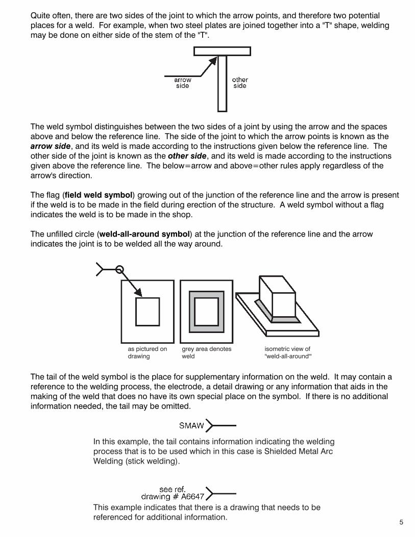
Quite often, there are two sides of the joint to which the arrow points, and therefore two potential places for a weld. For example, when two steel plates are joined together into a "T" shape, welding may be done on either side of the stem of the "T".
The weld symbol distinguishes between the two sides of a joint by using the arrow and the spaces above and below the reference line. The side of the joint to which the arrow points is known as the arrow side, and its weld is made according to the instructions given below the reference line. The other side of the joint is known as the other side, and its weld is made according to the instructionsgiven above the reference line. The below=arrow and above=other rules apply regardless of the arrow's direction.
The flag (field weld symbol) growing out of the junction of the reference line and the arrow is present iftheweldistobemadeinthefieldduringerectionofthestructure.Aweldsymbolwithoutaflagindicates the weld is to be made in the shop.
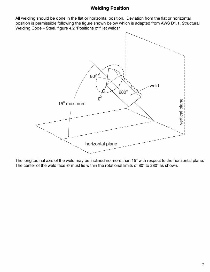
The unfilled circle (weld-all-around symbol) at the junction of the reference line and the arrow indicates the joint is to be welded all the way around.
The tail of the weld symbol is the place for supplementary information on the weld. It may contain a reference to the welding process, the electrode, a detail drawing or any information that aids in the making of the weld that does no have its own special place on the symbol. If there is no additional information needed, the tail may be omitted.
In this example, the tail contains information indicating the welding processthatistobeusedwhichinthiscaseisShieldedMetalArcWelding (stick welding).
This example indicates that there is a drawing that needs to be referenced for additional information.
as pictured ondrawing
grey area denotes weld
isometric view of"weld-all-around'"

6
Types of Welds and Their Symbols
Each type of weld has its own basic symbol, which is typically placed near the center of the reference line (and above or below it, depending on which side of the joint it's on). The symbol is a small drawing that can usually be interpreted as a simplified cross-section of the weld. The examples below show the most common types of welds that may be utilized on our products. They are shownin both arrow-side and other-side position and how they would appear in a complete weld symbol. This is not meant to be an all-inclusive list of weld symbols. The complete set of symbols is given in a standard published by American National Standards Institute (ANSI)andtheAmerican Welding Society (AWS):ANSI/AWS A2.4, Symbols for Welding and Nondestructive Testing.
fillet weld square groove weld "J" groove weld
"V" groove weld bevel groove weld plug welds and slot welds
fillet weld both sides square groove weld, arrow side "J" groove weld, arrow side
"V" groove weld, arrow side bevel groove weld, other side plug weld or slot weld,arrow side
Complete Weld Symbol Example
A=weldingprocessB=weldtypeC=weldsize
The above symbol is read as: deposit a 3/4" fillet weld on the arrow-side of the joint utilizing the Gas MetalArcWeldingProcess(Mig).
7
Welding Position
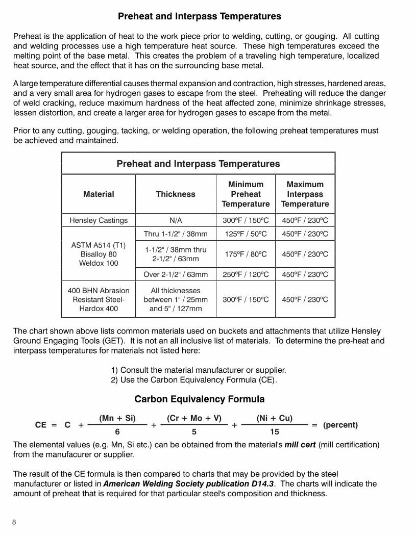
Allweldingshouldbedoneintheflatorhorizontalposition.DeviationfromtheflatorhorizontalpositionispermissiblefollowingthefigureshownbelowwhichisadaptedfromAWSD1.1,StructuralWeldingCode–Steel,figure4.2"Positionsoffilletwelds"
The longitudinal axis of the weld may be inclined no more than 15° with respect to the horizontal plane. The center of the weld face © must lie within the rotational limits of 80° to 280° as shown.
8
Preheat and Interpass Temperatures
Preheatistheapplicationofheattotheworkpiecepriortowelding,cutting,orgouging.Allcuttingand welding processes use a high temperature heat source. These high temperatures exceed the melting point of the base metal. This creates the problem of a traveling high temperature, localized heat source, and the effect that it has on the surrounding base metal.
Alargetemperaturedifferentialcausesthermalexpansionandcontraction,highstresses,hardenedareas,and a very small area for hydrogen gases to escape from the steel. Preheating will reduce the danger of weld cracking, reduce maximum hardness of the heat affected zone, minimize shrinkage stresses, lessen distortion, and create a larger area for hydrogen gases to escape from the metal.
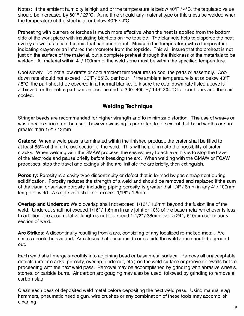
Prior to any cutting, gouging, tacking, or welding operation, the following preheat temperatures must be achieved and maintained.
The chart shown above lists common materials used on buckets and attachments that utilize Hensley Ground Engaging Tools (GET). It is not an all inclusive list of materials. To determine the pre-heat and interpass temperatures for materials not listed here: 1) Consult the material manufacturer or supplier. 2) Use the Carbon Equivalency Formula (CE).
Preheat and Interpass Temperatures
Material ThicknessMinimum Preheat
Temperature
Maximum Interpass
Temperature
Hensley Castings N/A 300ºF / 150ºC 450ºF / 230ºC
ASTMA514(T1) Bisalloy 80 Weldox 100
Thru 1-1/2" / 38mm 125ºF / 50ºC 450ºF / 230ºC
1-1/2" / 38mm thru 2-1/2" / 63mm
175ºF / 80ºC 450ºF / 230ºC
Over 2-1/2" / 63mm 250ºF / 120ºC 450ºF / 230ºC
400BHNAbrasion ResistantSteel-
Hardox 400
Allthicknesses between 1" / 25mm
and 5" / 127mm300ºF / 150ºC 450ºF / 230ºC
Carbon Equivalency Formula
CE = C +(Mn + Si)
+(Cr + Mo + V)
+(Ni + Cu)
= (percent)6 5 15
Theelementalvalues(e.g.Mn,Sietc.)canbeobtainedfromthematerial'smill cert (mill certification) from the manufacurer or supplier.
The result of the CE formula is then compared to charts that may be provided by the steel manufacturer or listed in American Welding Society publication D14.3. The charts will indicate the amount of preheat that is required for that particular steel's composition and thickness.
9
Welding Technique
Stringerbeadsarerecommendedforhigherstrengthandtominimizedistortion.Theuseofweaveorwash beads should not be used, however weaving is permitted to the extent that bead widths are no greater than 1/2" / 12mm.
Craters: When a weld pass is terminated within the finished product, the crater shall be filled to at least 85% of the full cross section of the weld. This will help eliminate the possibility of crater cracks.WhenweldingwiththeSMAWprocess,theeasiestwaytoachievethisistostopthetraveloftheelectrodeandpausebrieflybeforebreakingthearc.WhenweldingwiththeGMAWorFCAWprocesses, stop the travel and extinguish the arc, initiate the arc briefly, then extinguish.
Porosity: Porosity is a cavity-type discontinuity or defect that is formed by gas entrapment during solidification. Porosity reduces the strength of a weld and should be removed and replaced if the sum of the visual or surface porosity, including piping porosity, is greater that 1/4" / 6mm in any 4" / 100mm lengthofweld.Asinglevoidshallnotexceed1/16"/1.6mm.
Overlap and Undercut: Weld overlap shall not exceed 1/16" / 1.6mm beyond the fusion line of the weld. Undercut shall not exceed 1/16" / 1.6mm in any joint or 10% of the base metal whichever is less. In addition, the accumulative length is not to exceed 1-1/2" / 38mm over a 24" / 610mm continuous section of weld.
Arc Strikes:Adiscontinuityresultingfromaarc,consistingofanylocalizedre-meltedmetal.Arcstrikesshouldbeavoided.Arcstrikesthatoccurinsideoroutsidetheweldzoneshouldbegroundout.
Each weld shall merge smoothly into adjoining bead or base metal surface. Remove all unacceptable defects (crater cracks, porosity, overlap, undercut, etc.) on the weld surface or groove sidewalls before proceeding with the next weld pass. Removal may be accomplished by grinding with abrasive wheels, stones,orcarbideburrs.Aircarbonarcgougingmayalsobeused,followedbygrindingtoremoveallcarbon slag.
Clean each pass of deposited weld metal before depositing the next weld pass. Using manual slag hammers, pneumatic needle gun, wire brushes or any combination of these tools may accomplish cleaning.
Notes: If the ambient humidity is high and or the temperature is below 40°F / 4°C, the tabulated value shouldbeincreasedby80°F/27°C.Atnotimeshouldanymaterialtypeorthicknessbeweldedwhenthe temperature of the steel is at or below 40°F / 4°C.
Preheating with burners or torches is much more effective when the heat is applied from the bottom side of the work piece with insulating blankets on the topside. The blankets help to disperse the heat evenlyaswellasretaintheheatthathasbeeninput.Measurethetemperaturewithatemperatureindicating crayon or an infrared thermometer from the topside. This will insure that the preheat is not just on the surface of the material, but a complete preheat through the thickness of the materials to be welded.Allmaterialwithin4"/100mmoftheweldzonemustbewithinthespecifiedtemperature.
Cool slowly. Do not allow drafts or cool ambient temperatures to cool the parts or assembly. Cool down rate should not exceed 130°F / 55°C, per hour. If the ambient temperature is at or below 40°F / 5°C, the part should be covered in a thermal blanket to insure the cool down rate listed above is achieved, or the entire part can be post-heated to 300°-400°F / 149°-204°C for four hours and then air cooled.
10
Welding Weld-On Noses
BE SURE TO READ ALL INSTRUCTIONS PRIOR TO STARTING ANY WELDING!
XS / Kmax Weld-On Noses
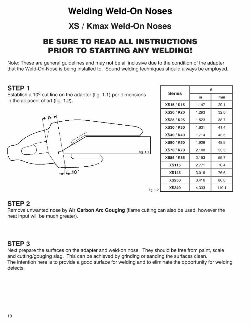
Note: These are general guidelines and may not be all inclusive due to the condition of the adapter thattheWeld-On-Noseisbeinginstalledto.Soundweldingtechniquesshouldalwaysbeemployed.
SeriesA
in mm
XS15 / K15 1.147 29.1
XS20 / K20 1.293 32.8
XS25 / K25 1.523 38.7
XS30 / K30 1.631 41.4
XS40 / K40 1.714 43.5
XS50 / K50 1.926 48.9
XS70 / K70 2.108 53.5
XS85 / K85 2.193 55.7
XS115 2.771 70.4
XS145 3.016 76.6
XS250 3.416 86.8
XS340 4.333 110.1
STEP 1Establish a 10O cut line on the adapter (fig. 1.1) per dimensionsin the adjacent chart (fig. 1.2).
fig. 1.1
fig. 1.2
STEP 2Remove unwanted nose by Air Carbon Arc Gouging (flame cutting can also be used, however the heat input will be much greater).
STEP 3Next prepare the surfaces on the adapter and weld-on nose. They should be free from paint, scale and cutting/gouging slag. This can be achieved by grinding or sanding the surfaces clean.The intention here is to provide a good surface for welding and to eliminate the opportunity for welding defects.
11
Welding Weld-On Noses
XS / Kmax Weld-On Noses
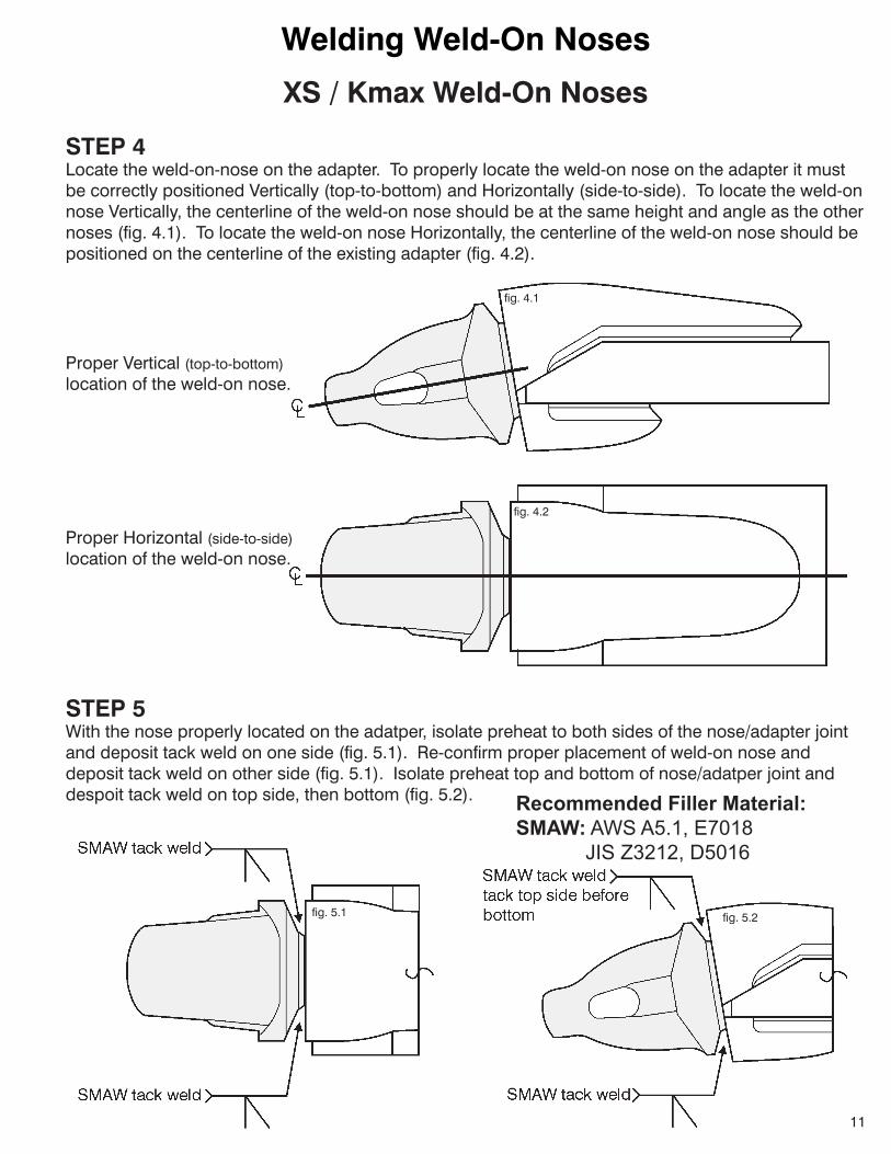
STEP 4Locate the weld-on-nose on the adapter. To properly locate the weld-on nose on the adapter it must be correctly positioned Vertically (top-to-bottom) and Horizontally (side-to-side). To locate the weld-on nose Vertically, the centerline of the weld-on nose should be at the same height and angle as the other noses (fig. 4.1). To locate the weld-on nose Horizontally, the centerline of the weld-on nose should be positioned on the centerline of the existing adapter (fig. 4.2).
fig. 4.1
Proper Vertical (top-to-bottom)location of the weld-on nose.
fig. 4.2
Proper Horizontal (side-to-side)location of the weld-on nose.
STEP 5With the nose properly located on the adatper, isolate preheat to both sides of the nose/adapter jointand deposit tack weld on one side (fig. 5.1). Re-confirm proper placement of weld-on nose and deposit tack weld on other side (fig. 5.1). Isolate preheat top and bottom of nose/adatper joint and despoit tack weld on top side, then bottom (fig. 5.2).
fig. 5.1 fig. 5.2
Recommended Filler Material:SMAW: AWS A5.1, E7018 JIS Z3212, D5016
12
Welding Weld-On Noses
XS / Kmax Weld-On Noses
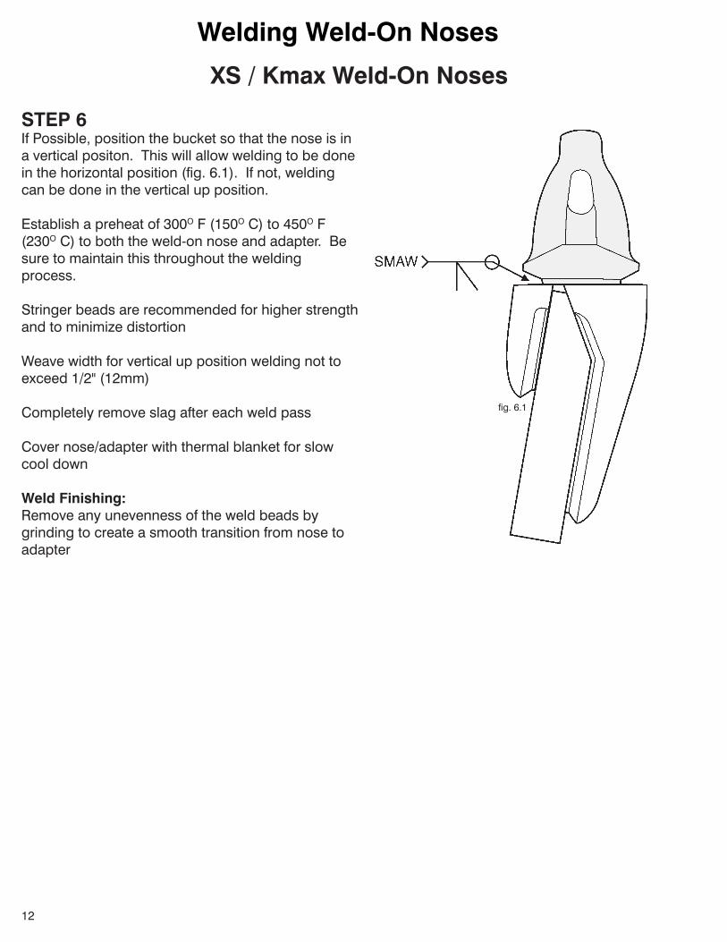
STEP 6If Possible, position the bucket so that the nose is ina vertical positon. This will allow welding to be done in the horizontal position (fig. 6.1). If not, welding can be done in the vertical up position.
Establish a preheat of 300O F (150O C) to 450O F (230O C) to both the weld-on nose and adapter. Be sure to maintain this throughout the welding process.
Stringerbeadsarerecommendedforhigherstrengthand to minimize distortion
Weave width for vertical up position welding not to exceed 1/2" (12mm)
Completely remove slag after each weld pass
Cover nose/adapter with thermal blanket for slow cool down
Weld Finishing:Remove any unevenness of the weld beads by grinding to create a smooth transition from nose to adapter
fig. 6.1

13
Welding Weld-On Noses
BE SURE TO READ ALL INSTRUCTIONS PRIOR TO STARTING ANY WELDING!
SPECIAL NOTESRecommended Filler Material: AWSspecificationA5.2,classE71T-1wirefortheGMAWprocess (preferredprocess).AWSspecificationA5.1,classE7018,stick electrodefortheSMAWprocess(notthedesiredprocessduetothe numberofstopsandstartswithintheweldment).Stickelectrodes should be kept in a heated rod oven at 250°F/120°C prior to use. Seemanufacturesrecommendedproceduresforstorageand preservation of low hydrogen electrodes.
Recommended Weld Type: Stringerbeadsarerecommendedforhigherstrengthandless distortion. The use of weave or wash beads is NOT recommended andshouldnotbeused.Arcstrikesshouldbeavoidedor ground out.
STEP 1RemovewornnoseusingtheAirCarbonArcGougingProcess.Caremustbetakentocreatea“plane” for the proper nose angle, (up and down), as well as the correct distance, (front to back), for the weld-on-nose. The gouged surface should be ground to remove all carbon slag and provide a clean and smooth surface for welding.
Mining Size Noses(for machine classes over 200 tons)
Note: These are general guidelines and may not be all inclusive due to the condition of the adapter thattheWeld-On-Noseisbeinginstalledto.Soundweldingtechniquesshouldalwaysbeemployed.
STEP 2 The weld-on-nose and the base adapter should be preheated to 300OF/150O C - 350OF/180OC. Use an infrared thermometer or temperature indicating crayons to measure temperature. This temperature shouldbemaintainedthroughouttheweldingprocess.Alocalizedpre-heatcanbeusedfortackuppurposes.
STEP3FitWeld-On-Nosetorequirednoseangle,(upanddown),andfronttobackdistance.Allowa1/8”rootopening between the weld-on-nose and the base adapter and tack in place (fig. 3.1).Starter/Run-outTabsshouldbeusedatthetopandthebottomoftheweldjoint(fig.3.2-fig3.3).

14
Welding Weld-On NosesMining Size Noses
(for machine classes over 200 tons)
fig. 3.1
fig. 3.2
fig. 3.3
15
Welding Weld-On Noses
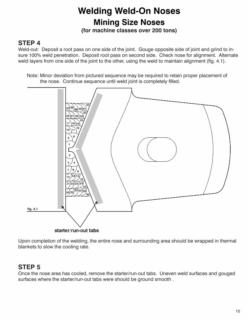
STEP 4Weld-out: Deposit a root pass on one side of the joint. Gouge opposite side of joint and grind to in-sure100%weldpenetration.Depositrootpassonsecondside.Checknoseforalignment.Alternateweld layers from one side of the joint to the other, using the weld to maintain alignment (fig. 4.1).
Mining Size Noses(for machine classes over 200 tons)
fig. 4.1
Upon completion of the welding, the entire nose and surrounding area should be wrapped in thermal blankets to slow the cooling rate.
Note:Minordeviationfrompicturedsequencemayberequiredtoretainproperplacementof the nose. Continue sequence until weld joint is completely filled.
STEP 5Once the nose area has cooled, remove the starter/run-out tabs. Uneven weld surfaces and gouged surfaces where the starter/run-out tabs were should be ground smooth .
42
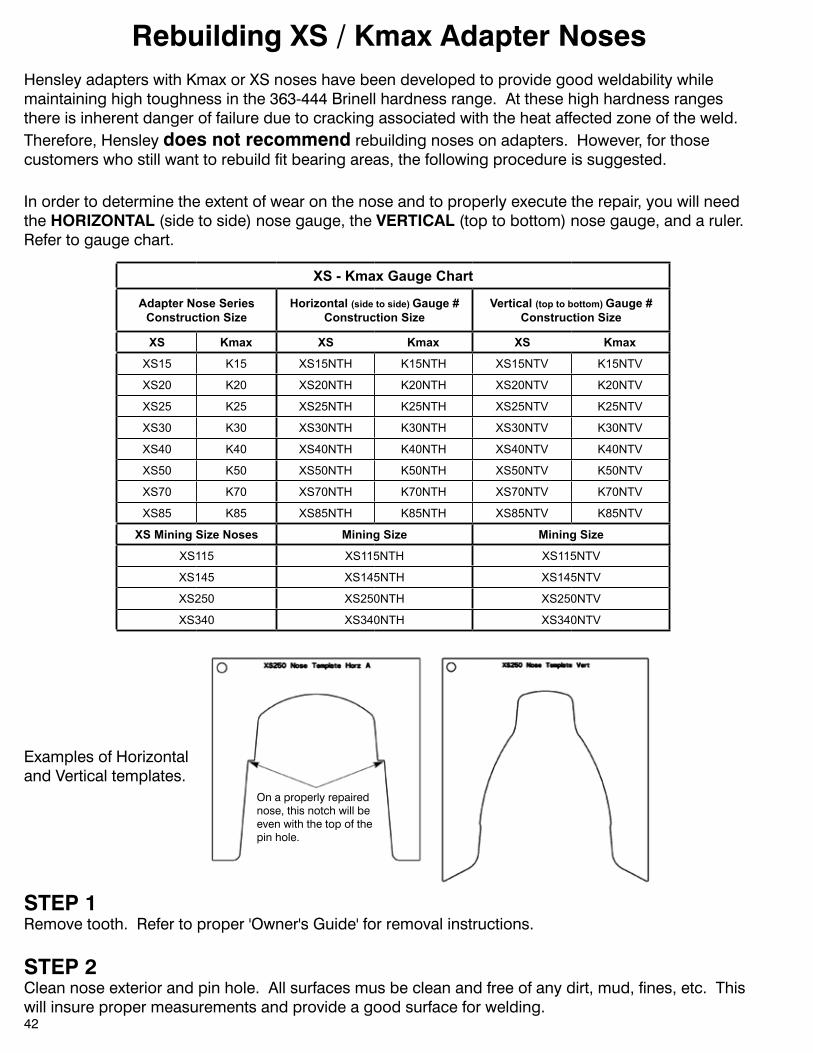
Rebuilding XS / Kmax Adapter NosesHensleyadapterswithKmaxorXSnoseshavebeendevelopedtoprovidegoodweldabilitywhilemaintaininghightoughnessinthe363-444Brinellhardnessrange.Atthesehighhardnessrangesthere is inherent danger of failure due to cracking associated with the heat affected zone of the weld. Therefore, Hensley does not recommend rebuilding noses on adapters. However, for those customers who still want to rebuild fit bearing areas, the following procedure is suggested.
Examples of Horizontaland Vertical templates.
On a properly repairednose, this notch will beeven with the top of the pin hole.
In order to determine the extent of wear on the nose and to properly execute the repair, you will need the HORIZONTAL (side to side) nose gauge, the VERTICAL (top to bottom) nose gauge, and a ruler. Refer to gauge chart.
STEP 1Remove tooth. Refer to proper 'Owner's Guide' for removal instructions.
STEP 2Cleannoseexteriorandpinhole.Allsurfacesmusbecleanandfreeofanydirt,mud,fines,etc.Thiswill insure proper measurements and provide a good surface for welding.
XS - Kmax Gauge Chart
Adapter Nose Series Construction Size
Horizontal (side to side) Gauge #Construction Size
Vertical (top to bottom) Gauge #Construction Size
XS Kmax XS Kmax XS Kmax
XS15 K15 XS15NTH K15NTH XS15NTV K15NTV
XS20 K20 XS20NTH K20NTH XS20NTV K20NTV
XS25 K25 XS25NTH K25NTH XS25NTV K25NTV
XS30 K30 XS30NTH K30NTH XS30NTV K30NTV
XS40 K40 XS40NTH K40NTH XS40NTV K40NTV
XS50 K50 XS50NTH K50NTH XS50NTV K50NTV
XS70 K70 XS70NTH K70NTH XS70NTV K70NTV
XS85 K85 XS85NTH K85NTH XS85NTV K85NTV
XS Mining Size Noses Mining Size Mining Size
XS115 XS115NTH XS115NTV
XS145 XS145NTH XS145NTV
XS250 XS250NTH XS250NTV
XS340 XS340NTH XS340NTV
43
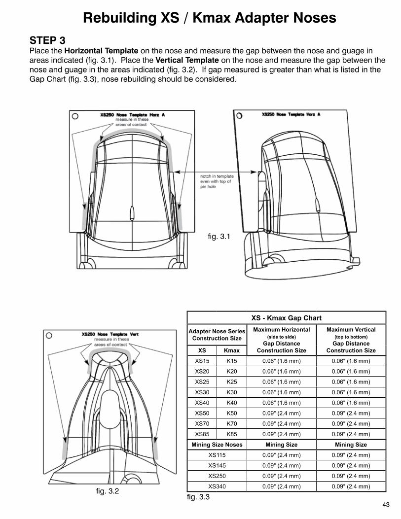
STEP 3Place the Horizontal Template on the nose and measure the gap between the nose and guage in areas indicated (fig. 3.1). Place the Vertical Template on the nose and measure the gap between the nose and guage in the areas indicated (fig. 3.2). If gap measured is greater than what is listed in the Gap Chart (fig. 3.3), nose rebuilding should be considered.
Rebuilding XS / Kmax Adapter Noses
fig. 3.1
fig. 3.2fig. 3.3
XS - Kmax Gap Chart
Adapter Nose Series Construction Size
Maximum Horizontal (side to side)
Gap Distance Construction Size
Maximum Vertical (top to bottom)
Gap Distance Construction SizeXS Kmax
XS15 K15 0.06" (1.6 mm) 0.06" (1.6 mm)
XS20 K20 0.06" (1.6 mm) 0.06" (1.6 mm)
XS25 K25 0.06" (1.6 mm) 0.06" (1.6 mm)
XS30 K30 0.06" (1.6 mm) 0.06" (1.6 mm)
XS40 K40 0.06" (1.6 mm) 0.06" (1.6 mm)
XS50 K50 0.09" (2.4 mm) 0.09" (2.4 mm)
XS70 K70 0.09" (2.4 mm) 0.09" (2.4 mm)
XS85 K85 0.09" (2.4 mm) 0.09" (2.4 mm)
Mining Size Noses Mining Size Mining Size
XS115 0.09" (2.4 mm) 0.09" (2.4 mm)
XS145 0.09" (2.4 mm) 0.09" (2.4 mm)
XS250 0.09" (2.4 mm) 0.09" (2.4 mm)
XS340 0.09" (2.4 mm) 0.09" (2.4 mm)
18
STEP 4If it has been determined that the nose will be rebuilt, it must be preheaated prior to depositing any weld. Preheat the nose to between 300OF / 150OC and 400OF / 204OC. Temperature should be measured with a temperature indicating crayon or an infrared thermometer.
Due to the shape of the nose, an all position stick electrode or wire is recommended using the filler material listed in the chart below..
Rebuilding XS / Kmax Adapter Noses
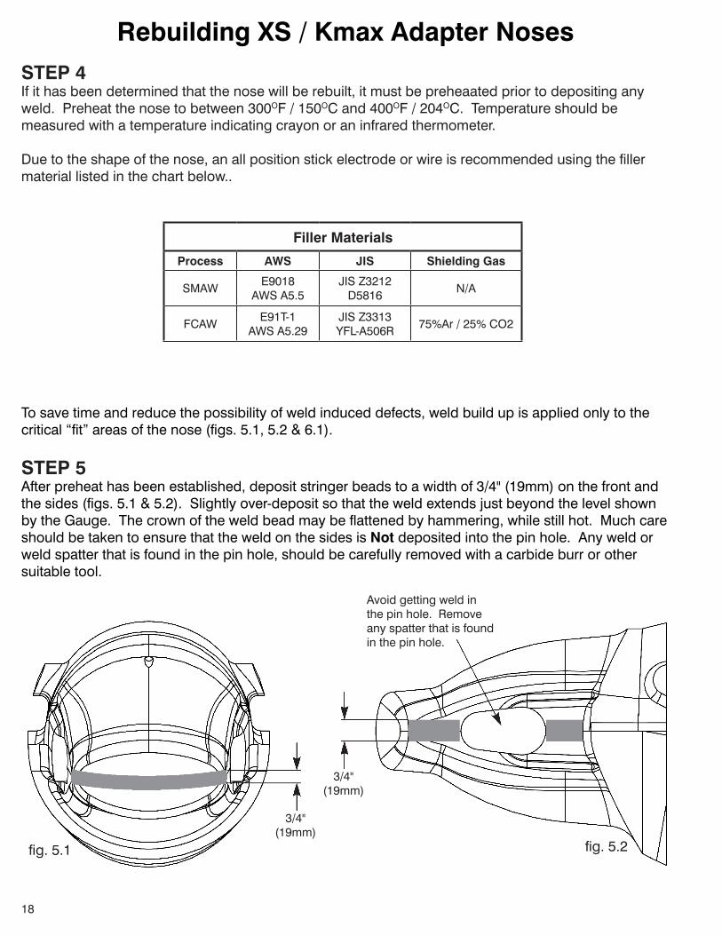
To save time and reduce the possibility of weld induced defects, weld build up is applied only to the critical “fit” areas of the nose (figs. 5.1, 5.2 & 6.1).
STEP 5Afterpreheathasbeenestablished,depositstringerbeadstoawidthof3/4"(19mm)onthefrontandthesides(figs.5.1&5.2).Slightlyover-depositsothattheweldextendsjustbeyondthelevelshownbytheGauge.Thecrownoftheweldbeadmaybeflattenedbyhammering,whilestillhot.Muchcareshould be taken to ensure that the weld on the sides is Not depositedintothepinhole.Anyweldorweld spatter that is found in the pin hole, should be carefully removed with a carbide burr or other suitable tool.
3/4"(19mm)
3/4"(19mm)
Avoidgettingweldinthe pin hole. Removeany spatter that is found in the pin hole.
fig. 5.1 fig. 5.2
Filler Materials
Process AWS JIS Shielding Gas
SMAWE9018 AWSA5.5
JISZ3212 D5816
N/A
FCAWE91T-1
AWSA5.29JISZ3313 YFL-A506R
75%Ar/25%CO2

19
STEP 6Depositstringerbeadstoawidthof3/4"(19mm)onthetopandbottomofthenose(fig.6.1).Again,the high crown of the weld bead may be flattened by hammering, while still hot.
Rebuilding XS / Kmax Adapter Noses
fig. 6.1
3/4"(19mm)
STEP 7Grind weld beads so that the Horizontal template fits over the nose and the notch in the template lines up with the TOP of the pin hole (fig. 7.1). Top and bottom are ground to accept the Vertical template (fig.7.2).Minoradjustmentsinfitmaybeachievedbypeening.Oncethenosehasbeenground/peened to accept both templates, check fit the nose with an actual tooth. Insert tooth pin and turn to thelockedposition.Thelockingtagofthepinshouldturnfreely.Referto'Owner'sManual'fortooth/pin installation and removal procedures.
fig. 7.1 fig. 7.2
20
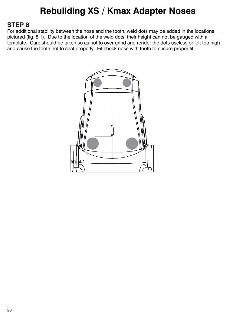
STEP 8For additional stability between the nose and the tooth, weld dots may be added in the locations pictured (fig. 8.1). Due to the location of the weld dots, their height can not be gauged with a template. Care should be taken so as not to over grind and render the dots useless or left too high and cause the tooth not to seat properly. Fit check nose with tooth to ensure proper fit.
Rebuilding XS / Kmax Adapter Noses
fig. 8.1
21
Welding Terms and Definitions
• AirCarbonArcGouging–Acarbonarcprocessthatremovesmoltenmetalwithajetofair.
• AmericanWeldSociety(AWS)–Anonprofittechnicalsocietyorganizedandfoundedforthepurposeofadvancingtheartandscienceofwelding.TheAWSpublishescodesandstandardsconcerning all phases of welding.
• BritishStandardsInstitute(BSI)–Anonprofitconcern.Theprincipalobjectistocoordinatethe efforts of producers and users for the improvement, standardization, and simplification of engineering and industrial material.
• Crater–Adepressionintheweldfaceattheterminationofaweldbead.
• Defect–Adiscontinuityordiscontinuitiesthatbynatureoraccumulatedeffect(forexample,accumulative length of undercut not to exceed 1.5" / 38mm over a 24" / 609mm section of weld) render a part or product unable to meet minimum applicable acceptance standards.
• DeutschesInstitutefuerNormung(DIN)–GermanStandard
• DirectCurrentElectrodePositive(DCEP)–Thearrangementofdirectcurrentarcweldingleadsin which the electrode is the positive pole and the workpiece is the negative pole of the welding arc.
• Discontinuity–Aninterruptionofthetypicalstructureofamaterial,suchaslackofhomogeneityin its mechanical, metallurgical, or physical characteristics.
• Electrode–Acomponentoftheelectricalcircuitthatterminatesatthearc,moltenconductiveslag, or base metal.
• FillerMaterial–Thematerialtobeaddedinmakingaweldedjoint.
• FilletWeld–Aweldofapproximatelytriangularcrosssectionjoiningtwosurfacesapproximatelyat right angles to each other in a lap joint, T-joint, or corner joint.
• FluxCoredArcWelding(FCAW)–Anarcweldingprocessthatusesanarcbetweenacontinuous filler metal electrode and the weld pool. The process is used with shielding gas from a flux contained within the tubular wire electrode, with or without additional shielding from an externally supplied gas and without the application of pressure.
• FrancaisedeNormalisation(NF)–FrenchStandard
• GasMetalArcWelding(GMAW)–Anarcweldingprocessthatusesanarcbetweenacontinuous filler metal electrode and the weld pool. The process is used with shielding from an externally supplied gas and without the application of pressure.
• JapaneseIndustrialStandards(JIS)–TheJapaneseStandardsAssociationpublishesstandards, including metals, welding filler materials, etc.
• Layer–Astratumofweldmetalconsistingofoneormoreweldbeads.
22
Welding Terms and Definitions
• Overlap–Theprotrusionofweldmetalbeyondtheweldtoeorweldroot.
• Porosity–Acavity-typediscontinuityordefectformedbygasentrapmentduringsolidification.
• Preheat–Theapplicationofheattotheworkpiecepriortoweldingcuttingorgouging.
• Root–Thepoint,shownincrosssection,atwhichtheweldmetalextendsfurthestintoajointand intersects the base metal.
• Run-offWeldTab–Additionalmaterialthatextendsbeyondtheendofthejoint,onwhichtheweld is terminated.
• ShieldedMetalArcWelding(SMAW)-Anarcweldingprocesswithanarcbetweenacoveredelectrode and the weld pool. The process is used with shielding from the decomposition of the electrode covering, without the application of pressure, and with filler metal from the electrode.
• ShieldingGas–Protectivegasusedtopreventorreduceatmosphericcontaminationofaweld,especially by oxygen and nitrogen.
• StarterWeldTab–Additionalmaterialthatextendsbeyondthebeginningofthejoint,onwhichthe weld is started.
• StringerBead–Atypeofbeadmadewithoutappreciableweavingmotion.
• TackWeld–Aweldmadetoholdthepartsofaweldmentinproperalignmentuntilthefinalwelds are made.
• Undercut–Agroovemeltedintothebasemetaladjacenttotheweldtoeorrootandleftunfilledby weld metal.
• WeldGroove–Achannelinthesurfaceofaworkpieceoranopeningbetweentwojointmembers that provides space to contain weld.
• WeldToe–Thejunctionoftheweldfaceandthebasemetal.
• WeldingSequence–Theorderofmakingweldsinaweldment.

23
THISPAGEINTENTIONALLYLEFTBLANK
24
SAFETY FIRST: Hensleyrecommendsthatyouuseasoft-facedhammerandANSI-approved(Z87.1)eyeprotectionwhileusingourproducts.
Hensley Industries, Inc.2108JoeFieldRoad•Dallas,Texas
75229U.S.A.Customer Service
(888)406-6262U.S./Canada(972) 406 - 6262 all other locations
Hensley AttachmentsADivisionofHensleyIndustries,Inc.
800SouthFifth•Mansfield,Texas76063U.S.A
(800)433-3144U.S./Canada(817) 477 - 3167 all other locations
www. hensleyind.comCopyright © 2009 Hensley Industries, Inc.
This publication is protected under the copyright laws of the United States. Unauthorized duplication or distribution is prohibited.