Embed Size (px)
Citation preview

WELDER’SVisual InspectionHANDBOOK
May 2013
-- NOTE --This handbook is NOT intended to serve as a work procedure or to replace any existing procedures. It is solely intended to provide basic information about weld conditions, weld gauges, symbols and weld terms. Refer to local procedures for technical or other specific data.

Table of Contents PageVisual Inspection Responsibilities and Technique iHow to Measure Fillet Weld Size 1 Cracks 2 Underfill 4 Burn Through 6 Incomplete Fusion 8 Roughness 10 Overlap 12 Undersized Fillet Weld 14 Incomplete Penetration 16 Undercut 18 Corner-Melt 20 End-Melt 22 Concave Fillet Weld 24 Convex Fillet Weld 26 Arc Strikes 28 Other Fabrication Scars 30 Porosity 32 Spatter 34 Slag 36 Weld Reinforcement 38 Melt Through 40 Offset 42 Oxidation 44 Crater Pit 46 Paint 48Types of Weld Joints 50Parts of a Weld 53Structural Joint Numbering System 54Standard Welding Symbol Layout 60Standard Welding Symbols 61Using Finger Gauge 67Using Bridgecam Gauge 70Definitions 73
VT Attributes

Visual Inspection Responsibilities1. When – Final visual inspections must be performed:
a) Whentheweldiscomplete,andinthefinalsur-face and heat treated conditions
b) Before other NDT (when required)c) Before being made inaccessible for inspection
2. Where – the weld inspection zone:a) All work - Completed weld faces plus ½ inch on
both sides of weld shall be visually inspected for the entire length of the weld.
b) To gauge weld size:(1). Gauge where the weld size visually ap-
pears to be the smallest(2). Iftheweldlengthisfivefeetorless,gauge
a minimum of once per weld(3). Iftheweldlengthisgreaterthanfivefeet,
gaugeaminimumofonceeveryfivefeetVisual Inspection Technique1. What–Inordertoperformfinalvisualinspectionyou
need:a) Adequatelighting(useflashlightasneeded)b) Weldgauges(bridgecamandfingergauges
recommended)c) Prescription glasses (as required)
2. How – Distance and angle:a) The inspector’s eyes should be within 24 inches
of the surface to be inspected and b) At an angle of at least 30 degrees to the surface
being inspected.
i

1
How to Measure FILLET WELD SIZE(Correct Size)
The leg lengths and throat of the largest triangle that can bedrawnwithinthefilletweldcrosssection.
Size
Leg/Size
Leg/Size
SizeLeg
Leg
Throat*
* See parts of a weld
Throat*

2
CRACKS

3
CRACKS
Definition
Atear,fractureorfissureintheweldorbasemetalappearing as a broken, jagged or straight line.
NOTE: Cracks are the most serious defect!
Preventive Action1. Remove contaminants from the joint (rust,
grease, moisture, etc.) prior to welding. 2. Apply and maintain required preheat. 3. Do not allow the base material to cool too
quickly. 4.Maintainfillermetalcontrolrequirements.5.Usecorrectfillermetaltypeforthejoint.6. Apply proper bead size and sequencing to
eliminate excessive distortion and/or stress in the base material.
Corrective Action
Repair in accordance with local procedures.

4
UNDERFILL

5
UNDERFILL
Definition
The amount of weld that is below a straight line drawn from the edges of the joint preparation of a groove weld, with the exception of allowable undercut.
Preventive Action
1. During welding of the reinforcement, gauge bead heights in any location that appears to be lower than the rest of the bead.2. Adjust amps/volts.3. Slow travel speed to allow increased weld puddle volume. 4. Sequence weld passes so that the toes of the beadssufficientlycoveroneanother, minimizing valleys.
Corrective Action
Apply additional weld beads until the joint isadequatlyfilled.(flushorabove)

6
BURN THROUGH

7
BURN THROUGH
Definition
Excessive heat and/or penetration that results in a hole completely through the backing ring or strip, fused root, or adjacent base material.
Preventive Action
1. Reduce amps/volts.2. Increase travel speed.3. Maintain appropriate arc length/wire stickout.4. Use ceramic tape or approved metal backing strap on areas with root gap.
Corrective Action
1. Place ceramic tape or approved metal backing strap on the bottom side of the hole.
2.Weldrepairthefirstsideoftheholefromtheeasiest side to weld.
3.Oncesufficientweldmetalhasbeendepositedon the easiest top side, grind or carbon arc the other side of the hole to sound metal.
4. Weld the other side of the hole to the appropriate size or height.

8
INCOMPLETE FUSION

9
INCOMPLETE FUSION
Definition
A situation where the weld metal does not fuse or completely bond with the base metal or previ-ously deposited weld metal.
Preventive Action
1. Increase amps/volts.2. Decrease travel speed.3. Maintain appropriate arc length/wire stickout.4. Adjust torch/rod angle. 5. Ensure previous beads are free of overlap
(bead roll-over) and slag prior to welding additional passes.
Corrective Action
1. Grind or carbon arc the weld to sound metal. 2. Weld repair the affected area.

ROUGHNESS
10

11
ROUGHNESS
Definition
Sharp ridges (irregularities) or deep valleys be-tween weld beads. The angle formed between the adjacent beads of the weld must be 90° or greater.
Preventive Action
1. Adjust amps/volts.2. Maintain a consistent travel speed.3. Maintain appropriate arc length/wire stickout.4. Adjust torch/rod angle.5. Sequence weld passes so that the toes of thebeadssufficientlycoveroneanother, minimizing valleys.6. Consult local Welding Engineering in cases where the base material is magnetized.
Corrective Action
1. Grind or carbon arc the weld to sound metal.2. Weld repair the affected area, if needed.

12
OVERLAP

13
OVERLAP
Definition
A condition where the weld metal rolls over forming an angle less than 90°. Sometimes referred to as “weld bead rollover.”
Preventive Action
1. Adjust amps/volts.2. Increase travel speed.3. Maintain appropriate arc length/wire stickout.4. Adjust torch/rod angle.
Corrective Action
1. Grind or carbon arc the weld to sound metal.2. Weld repair the affected area, if needed.

14
UNDERSIZED FILLET WELD
* See parts of a weld
Throat*

15
UNDERSIZED FILLET WELD
Definition
Anyfilletorfilletreinforcedweldthatdoesnotmeettheminimumsizerequirementsspecifiedon applicable fabrication documents.
Note: Skewedfilletsareexceptionallyproneto having undersized weld on sides that have greater than 90°jointfit-up.
Preventive Action
1. Apply weld layers until weld size is met on all sides of joint. 2. Adjust amps/volts.3. Decrease travel speed.4. Maintain proper wire stickout.5. Adjust torch/rod angle.6. Avoid over grinding.7. Sequence weld passes so that the toes of
thebeadssufficientlyoverlaponeanother.
Corrective ActionApply additional weld passes until the affected areas are the proper size.

16
INCOMPLETE PENETRATION
Pipe

17
INCOMPLETE PENETRATION
Definition
A situation where the weld metal does not penetrate as deeply as required.
Preventive Action
1. Increase the bevel angle and/or root opening ofthefit-up.Donotexceedtherequirementsof the joint design.
2. Ensure bevel edges of both members are lined up properly.
3. Increase amps/volts.4. Decrease travel speed. 5. Maintain appropriate arc length/wire stickout. 6. Adjust torch/rod angle.
Corrective Action
1. Grind or carbon arc the weld to sound metal.Note: Backgouge 2nd side to full penetration (remove fusion lines). Often, more than one fusion line will be present during back gouging. 2. Weld repair the affected area.

18
UNDERCUT
UNDERCUT GAUGE
BRIDGECAM

19
UNDERCUT
Definition
A groove melted into the base metal and left unfilledbyweldmetal.
Preventive Action
1. Decrease amps/volts.2. Decrease travel speed.3. Maintain appropriate arc length/wire stick-
out.4. Adjust torch/rod angle.5. Feed more wire into the puddle when manu-
al TIG welding.6. Increase stop time (dwell time) on weaved
beads.7. Use undercut gauge to verify acceptability.
Corrective Action
1. Grind the toe of the weld until the unaccept- able undercut blends smoothly into the base material. 2. Weld repair the affected area, if needed.

20
CORNER-MELT“as is”
condition
groundcondition

21
CORNER-MELT
Definition
A groove melted in a corner of a welded mem-berthatisleftunfilled.
Preventive Action1. Start welds at end of joint and work inward.2. Decrease amps/volts.3. Decrease travel speed.4. Maintain appropriate arc length/wire stick-
out.5. Adjust torch/rod angle.6. Feed more wire into the puddle when manu-
al TIG welding.7. Increase stop time (dwell time) on weaved
beads.8. Use undercut or bridgecam gauge to verify
acceptability.
Corrective Action
1. Grind the toe of the weld until the unaccept- able corner-melt blends smoothly into the base material. 2. Weld repair the affected area, if needed.

22
END-MELT
Gauged
“as is” condition
ground condition
1/4” or less

23
END-MELT
Definition
A groove melted into the end of a ¼ inch or lessweldedmemberthatisleftunfilledbyweldmetal.
Preventive Action
1. Start the weld passes at the ends, where possible.
2. Decrease amps/volts.3. Decrease travel speed.4. Maintain appropriate arc length/wire stick-
out.5. Adjust torch/rod angle.6. Feed more wire into the puddle when manu-
al TIG welding.7. Increase stop time (dwell time) on weaved
beads.8. Use undercut or bridgecam gauge to verify acceptability.
Corrective Action
1. Grind the toe of the weld until the unaccept- able end-melt blends smoothly into the base material. 2. Weld repair the affected area, if needed.

24
gauged
CONCAVE FILLET WELD

25
CONCAVE FILLET WELD
Definition
Afilletweldthatsinksinthecenter.
Preventive Action
1. Adjust amps/volts.2. Decrease travel speed.3. Maintain appropriate arc length/wire stickout.4. Adjust torch/rod angle.5. Feed more wire into the puddle when manu-
al TIG welding.6. Increase stop time (dwell time) on weaved
beads. 7. Sequence weld passes so that the toes of
thebeadssufficientlycoveroneanother.
Corrective Action
Apply additional weld passes until the concavity requirements have been met.

gauged
26
CONVEX FILLET WELD
Check Convexity using the Proper Size Wire
Convexity

27
CONVEX FILLET WELD
Definition
Afilletweldthatbulgesoutinthecenter.
Preventive Action
1. Adjust amps/volts.2. Increase travel speed.3. Maintain proper wire stickout. 4. Adjust torch/rod angle.5. Feed less wire into the puddle when manual
TIG welding.6. On multiple pass welds, avoid placing beads
too close together.
Corrective Action
Grind, carbon arc or weld the affected area untilthe convexity requirements have been met.

28
ARC STRIKES

29
ARC STRIKES
Definition
A discontinuity consisting of any localized re-melted metal, heat effected metal, or change in surfaceprofileofafinishedweldorbasemate-rial surface resulting from an electrical arc.Note: Arc strikes may develop stress risers, which could lead to cracking.
Preventive Action
1. Prior to energizing welding equipment, re-place damaged welding lines and ground cables.
2. Ensure grounds are properly installed. 3. Hang lines on trees or J-hooks. 4.Keepgascupsfreeofweldspatteronflux
core processes. 5. Do not allow sub-arc tips to contact the base
material. 6. Be careful when striking an arc.
Corrective Action
1. Grind the affected area until the unaccept-able arc strike blends smoothly into the base material or weld face.
2. Weld repair the affected area, if needed.

30
OTHER FABRICATION SCARS

31
OTHER FABRICATION SCARS
Definition
Any accidental groove or cut that penetrates the surface of the metal. Sometimes called nicks, gouges or handling marks.
Preventive Action
1. Avoid dropping heavy or sharp objects on welds and surrounding base material.
2. Be careful when grinding, carbon arcing or using scaling hammer.
3. Use undercut gauge to verify scar accept- ability.
Corrective Action
1. Grind the affected area until the unaccept- able fabrication scar blends smoothly into the base material or weld face.
2. Weld repair the affected area, if needed.

32
POROSITY

33
POROSITY
Definition
Open holes formed by gas that was trapped when the weld cooled. Sometimes called “pin-holes.”
Preventive Action
1. Remove contaminants from the joint (rust, grease, moisture, etc.) prior to welding.
2. Maintainfillermetalcontrolrequirements.3. Maintain appropriate arc length/wire stickout. 4. Adjust torch/rod angle. 5. Use the largest size gas cup possible and
keep it free of spatter. 6. Position wind screens between the welding
operationandanyheavyflowofair.
Corrective Action
1. Completely remove porosity from all interme- diate weld areas. 2. Grind or carbon arc the affected area until the unacceptable porosity is removed from the weld. 3. Weld repair the affected area, if needed.

34
SPATTER
A 1/8" wide x 1/8" deep notch is for verifying size of spatter
1/4"

35
SPATTER
Definition
The metal particles expelled during welding that do not form a part of the weld.
Preventive Action1. Remove contaminants from the joint (rust, grease, moisture, etc.) prior to welding. 2.Maintainfillermetalcontrolrequirements.3. Use Refrasil to protect surrounding surfaces from secondary weld spatter. 4. Adjust amps/volts.5. Adjust torch/rod angle. 6. Maintain appropriate arc length/wire stickout. 7. Use ceramic tape or approved metal backing strap on areas with root gap. 8. Consult local Welding Engineering in cases where the base material is magnetized.
Corrective Action
1. Completely remove spatter from all interme- diate weld areas. 2. Remove all loose spatter with a needle gun. 3. Grind all tightly adhering, unacceptable spatter until it blends smoothly into the base material or weld.

36
SLAG
A 1/8" wide x 1/8" deep notch is for verifying size of slag
1/4"
37
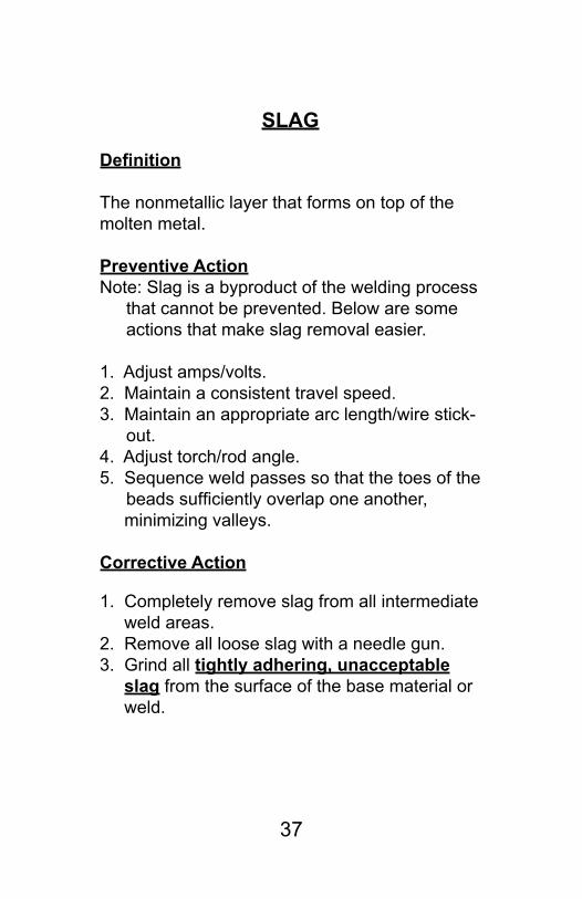
SLAG
Definition
The nonmetallic layer that forms on top of the molten metal.
Preventive ActionNote: Slag is a byproduct of the welding process
that cannot be prevented. Below are some actions that make slag removal easier.
1. Adjust amps/volts.2. Maintain a consistent travel speed. 3. Maintain an appropriate arc length/wire stick-
out. 4. Adjust torch/rod angle. 5. Sequence weld passes so that the toes of the
beadssufficientlyoverlaponeanother, minimizing valleys.
Corrective Action
1. Completely remove slag from all intermediate weld areas. 2. Remove all loose slag with a needle gun. 3. Grind all tightly adhering, unacceptable slag from the surface of the base material or weld.

38
WELD REINFORCEMENT
* Check local procedures for areas that have height restrictions.
*

39
WELD REINFORCEMENT
Definition
The amount of weld that is above a straight line drawn from the edges of the joint preparation of a groove weld.
Preventive Action
1. Adjust amps/volts.2. Increase travel speed. 3. Maintain appropriate wire stickout. 4. Adjust torch/rod angle. 5. Sequence beads so that the toes do not excessively overlap one another, creating high spots in the reinforcement.
Corrective Action
Grind or carbon arc areas of weld reinforcementthat exceed the maximum allowable height (if applicable).

40
MELT THROUGH

41
MELT THROUGH
Definition
Excessive heat and/or penetration that results in irregularity on the surface of the backing ring or strip, fused root or adjacent base material.
Preventive Action
1. Reduce amps/volts.2. Increase travel speed. 3. Maintain appropriate arc length/wire stick-
out. 4. Use ceramic tape or approved metal back-
ing strap on areas with root gap.
Corrective Action
1. Grind or carbon arc the weld to sound metal. 2. Weld repair the affected area, if needed.

42
OFFSET
43
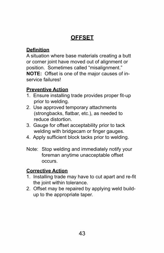
OFFSET
DefinitionA situation where base materials creating a butt or corner joint have moved out of alignment or position. Sometimes called “misalignment.”NOTE: Offset is one of the major causes of in-service failures!
Preventive Action1.Ensureinstallingtradeprovidesproperfit-up
prior to welding. 2. Use approved temporary attachments
(strongbacks,flatbar,etc.),asneededtoreduce distortion.
3. Gauge for offset acceptability prior to tack weldingwithbridgecamorfingergauges.
4.Applysufficientblocktackspriortowelding.
Note: Stop welding and immediately notify your foreman anytime unacceptable offset occurs.
Corrective Action1.Installingtrademayhavetocutapartandre-fit the joint within tolerance. 2. Offset may be repaired by applying weld build- up to the appropriate taper.

44
copper-nickel
steel
OXIDATION
45
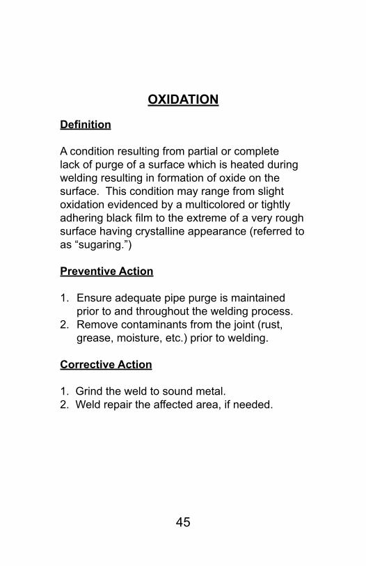
OXIDATION
Definition
A condition resulting from partial or complete lack of purge of a surface which is heated during welding resulting in formation of oxide on the surface. This condition may range from slight oxidation evidenced by a multicolored or tightly adheringblackfilmtotheextremeofaveryroughsurface having crystalline appearance (referred to as “sugaring.”)
Preventive Action
1. Ensure adequate pipe purge is maintained prior to and throughout the welding process.
2. Remove contaminants from the joint (rust, grease, moisture, etc.) prior to welding.
Corrective Action 1. Grind the weld to sound metal. 2. Weld repair the affected area, if needed.

46
CRATER PIT

47
CRATER PIT
Definition
A hole extending into the weld resulting from shrinkage during cooling.
Preventive Action
1. Remove contaminants from the joint (rust, grease, moisture, etc.) prior to welding.
2. When breaking the arc for TIG welding, rap-idly pop the trigger several times to avoid suddenpull-offs.Thiswillprovidesufficientpost purge of the weld puddle.
Corrective Action
1. Grind the weld to sound metal.2. Weld repair the affected area, if needed.

PAINT
48

49
PAINT
Definition
A pigmented oil or liquid that forms a coloring or protective coating when dry. May be found on the weld face or in the weld inspection area.
Preventive Action
Ensure installing trade adequately removes paint, paint stick markings and metal marker writings in theweldzonepriortofittingandwelding.
Corrective Action
Grind, wire wheel or needle gun the weld zonefree of paint prior to welding.

(Square)
(Single J)
(Single Bevel)
(Double Bevel)
50
Types of Weld Joints
Butt(Square)
(Double V)
(Single V)
(Single U)
Tee

51
Types of Weld Joints
Corner
(SingleBevel)
(Square)
(Single U)
(Single J)

52
Types of Weld Joints
Lap
Edge

53
Parts of a Weld
* This represents the theoretical throat (the minimum speci-fiedlegsizemultipliedby0.7)whichistheshortestdistancefrom the joint root to the hypotenuse (straight line drawn toe to toe) of the largest right triangle that can be drawn within thefilletweldcrosssection.

54
Structural JointNumbering System
First character (Letter)Designates type of joint:B - ButtC - CornerT - TeeL - LapPT - Partial PenetrationE - Edge
Second Character (Number)Designates Number of SidesWelded:1 - Welded One Side2 - Welded Both Sides
Third Character (Letter)Designates Configuration of Joint:S - Square GrooveV - Beveled or V GrooveU - U-Shaped GrooveJ - J-Shaped Groove
Period Used for Separation
Fourth Character (Number)Is Assigned In Sequence, 1,2,3, Etc., to Cover Distinctive Joint Differences such as Bevel Angle, Root Opening, With Backing, Without Backing, Etc.
B 2 V . 3

55
Structural JointNumbering System
EXAMPLES
C1V.2
Corner Joint
Welded One Side
Single BeveledGroove

56
Structural JointNumbering System
EXAMPLES
T2V.2
Tee Joint
Welded Both Sides
Double BeveledGroove

57
Structural JointNumbering System
EXAMPLES
B2V.1
Butt Joint
Welded Both Sides
Single VGroove

58
Structural JointNumbering System
EXAMPLES
B1V.1
Butt Joint Single VGroove
Welded One Side

59
Structural JointNumbering System
EXAMPLES
B2V.3
Butt Joint
Welded Both Sides
Double V Groove

60
Standard Welding SymbolLayout
S
Weld Size
(Far or Other Side)
(Near or Arrow Side)
Weld Symbolor Reference
Elements in this area as shown regardless of
arrow orientationReference Ar-row
Weld all around Symbol
Reference Line

61
Standard Welding Symbols
Fillet Near Side
Fillet Far Side
Fillet Both Sides

62
Standard Welding Symbols
V Groove Far Side
V Groove Both Sides
V Groove Near Side

63
Standard Welding Symbols
Single Bevel Near Side
Single Bevel Far Side
Double Bevel

64
Standard Welding Symbols
Single Beveled Tee JointWelded One Side / Fillet Reinforced
T1V.1
Joint has a bevel
Fillet size near side

Standard Welding Symbols
65
Single Beveled Tee JointWelded Both Sides / Fillet Reinforced
T2V.1
Note: Backgouge and visualinspection required
Fillet size far side
Joint has a bevel
Fillet size near side

66
Standard Welding SymbolsPartial Penetration
Double Bevel Tee JointWelded both sides / Fillet Reinforced
Example of PT2V.1S=filletsizeB = depth of bevel
Fillet size far sideJoint is beveled both sides
Fillet size near side
SB
B
S
3/8 Fillet size far sideJoint is beveled1/2 deep both sides3/8 Fillet size near side
B
S
3/81/2
3/8

67
Using Finger Gauge to Measure:
Check Concavity using the Proper Size Wire
Check Convexity using the Proper Size Wire
Overlap angle less than 90°
Concavity
Convexity
Overlap/Roll Over

68
Use Finger Gauge to Measure Skewed Fillet and Fillet Reinforced Welds
Gauging Skewed WeldsFinger gauges are the only gauges capable of gauging skewed welds. Note that when the angle of the joint preparation is less than 90° the actual length of the weld legs will increase.
69
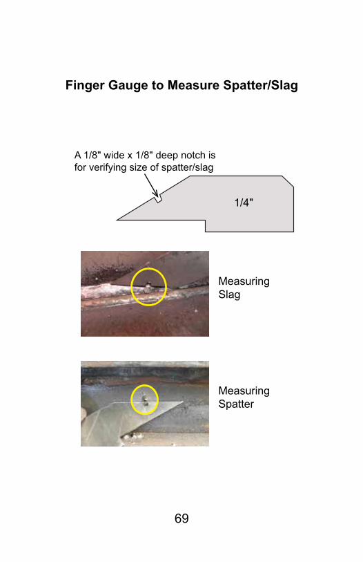
Finger Gauge to Measure Spatter/Slag
A 1/8" wide x 1/8" deep notch is for verifying size of spatter/slag
1/4"
Measuring Slag
Measuring Spatter

70
Using Bridgecam Gauge To Measure:Fillet Weld Throat
Fillet Leg Length
Read from theoretical throat scale.

71
Offset
Using Bridgecam Gauge To Measure:Reinforcement

72
UNDERCUT GAUGE
Using Gauges to Measure:Undercut

Definitions1. Completed weld – A weld that is completed and is
readyforfinalvisualinspection.2. Defect – Any harmful discontinuity that must be repaired
to be acceptable.3. Discontinuity – Any imperfection in the normal structure
orconfigurationofaweldorthebasematerialthatmay or may not need to be repaired.
4. Final visual inspection of welds– Visual inspection performedonacompletedweldinthefinalsurfacecondition and heat-treated condition.
5. Finished weld–Aweldthathasreceivedfinalinspection and has been accepted.
6. In-process visual inspection of welds- Visual inspection performed on intermediate passes of multi-pass welds.
7. Sound metal – Metal that contains no defects.8. Skewed fillet welds-Filletorfilletreinforcedweldthatis
less than 85° or greater than 95°.
♦ NDT – Nondestructive Testing VT = Visual Inspection MT = Magnetic Particle Inspection PT = Liquid Penetrant Inspection UT = Ultrasonic Inspection RT = Radiographic Inspection ET = Eddy Current Inspection
73

Scale Divisions Reference English Metric
-1/4
0
1/4
1/2
3/4
1”
-1/8
1/8
3/8
5/8
7/8
-3/16
-1/16
1/16
3/16
5/16
7/16
9/16
11/16
13/16
15/16
-7/32-5/32-3/32
-1/321/32
3/325/32
7/329/32
11/32
13/32
15/32
17/3219/32
21/3223/32
25/32
27/32
29/3231/32
0
- 6.35mm
25.4mm
10mm
20mm
- 5mm
5mm
15mm
25mm
Note: For training purposes only. Not to Scale!
1/643/645/647/649/64
11/6413/64