Embed Size (px)
Citation preview
BRITISH STANDARD BS EN 10296-2:2005
Welded circular steel tubes for mechanical and general engineering purposes — Technical delivery conditions —
Part 2: Stainless steel
The European Standard EN 10296-2:2005 has the status of a British Standard
ICS 77.140.75
���������������� ������������������������������� �������������
Lice
nsed
Cop
y: In
stitu
te O
f Tec
hnol
ogy
Tal
lagh
t, In
stitu
te o
f Tec
hnol
ogy,
Tue
Aug
29
11:0
4:21
BS
T 2
006,
Unc
ontr
olle
d C
opy,
(c)
BS
I

BS EN 10296-2:2005
This British Standard was published under the authority of the Standards Policy and Strategy Committee on 20 December 2005
© BSI 20 December 2005
ISBN 0 580 46783 X
National foreword
This British Standard is the official English language version of EN 10296-2:2005. It supersedes BS 6323-8:1982 which is withdrawn.
The UK participation in its preparation was entrusted to Technical Committee ISE/8, Steel pipes, which has the responsibility to:
A list of organizations represented on this committee can be obtained on request to its secretary.
Cross-references
The British Standards which implement international or European publications referred to in this document may be found in the BSI Catalogue under the section entitled “International Standards Correspondence Index”, or by using the “Search” facility of the BSI Electronic Catalogue or of British Standards Online.
This publication does not purport to include all the necessary provisions of a contract. Users are responsible for its correct application.
Compliance with a British Standard does not of itself confer immunity from legal obligations.
— aid enquirers to understand the text;
— present to the responsible international/European committee any enquiries on the interpretation, or proposals for change, and keep UK interests informed;
— monitor related international and European developments and promulgate them in the UK.
Summary of pages
This document comprises a front cover, an inside front cover, the EN title page, pages 2 to 31 and a back cover.
The BSI copyright notice displayed in this document indicates when the document was last issued.
Amendments issued since publication
Amd. No. Date Comments
Lice
nsed
Cop
y: In
stitu
te O
f Tec
hnol
ogy
Tal
lagh
t, In
stitu
te o
f Tec
hnol
ogy,
Tue
Aug
29
11:0
4:21
BS
T 2
006,
Unc
ontr
olle
d C
opy,
(c)
BS
I

EUROPEAN STANDARD
NORME EUROPÉENNE
EUROPÄISCHE NORM
EN 10296-2
December 2005
ICS 77.140.75
English Version
Welded circular steel tubes for mechanical and generalengineering purposes - Technical delivery conditions - Part 2:
Stainless steel
Tubes ronds soudés en acier pour utilisation en mécaniquegénérale et en construction mécanique - Conditions
techniques de livraison - Partie 2: Tubes en acierinoxydable
Geschweißte kreisförmige Stahlrohre für denMaschinenbau und allgemeine technische Anwendungen -
Technische Lieferbedingungen - Teil 2: NichtrostendeStähle
This European Standard was approved by CEN on 4 April 2005.
CEN members are bound to comply with the CEN/CENELEC Internal Regulations which stipulate the conditions for giving this EuropeanStandard the status of a national standard without any alteration. Up-to-date lists and bibliographical references concerning such nationalstandards may be obtained on application to the Central Secretariat or to any CEN member.
This European Standard exists in three official versions (English, French, German). A version in any other language made by translationunder the responsibility of a CEN member into its own language and notified to the Central Secretariat has the same status as the officialversions.
CEN members are the national standards bodies of Austria, Belgium, Cyprus, Czech Republic, Denmark, Estonia, Finland, France,Germany, Greece, Hungary, Iceland, Ireland, Italy, Latvia, Lithuania, Luxembourg, Malta, Netherlands, Norway, Poland, Portugal, Slovakia,Slovenia, Spain, Sweden, Switzerland and United Kingdom.
EUROPEAN COMMITTEE FOR STANDARDIZATIONC OM ITÉ EUR OP ÉEN DE NOR M ALIS AT IONEUROPÄISCHES KOMITEE FÜR NORMUNG
Management Centre: rue de Stassart, 36 B-1050 Brussels
© 2005 CEN All rights of exploitation in any form and by any means reservedworldwide for CEN national Members.
Ref. No. EN 10296-2:2005: E
Lice
nsed
Cop
y: In
stitu
te O
f Tec
hnol
ogy
Tal
lagh
t, In
stitu
te o
f Tec
hnol
ogy,
Tue
Aug
29
11:0
4:21
BS
T 2
006,
Unc
ontr
olle
d C
opy,
(c)
BS
I
EN 10296-2:2005 (E)
2
Contents
Page
Foreword ..................................................................................................................................................................3 Introduction..............................................................................................................................................................4 1 Scope ...........................................................................................................................................................5 2 Normative references .................................................................................................................................5 3 Terms and definitions.................................................................................................................................6 4 Symbols.......................................................................................................................................................6 5 Classification and designation ..................................................................................................................6 6 Information to be supplied by the purchaser............................................................................................7 7 Manufacturing process...............................................................................................................................8 8 Requirements ..............................................................................................................................................9 9 Inspection and testing ..............................................................................................................................18 10 Sampling....................................................................................................................................................20 11 Test methods.............................................................................................................................................22 12 Marking ......................................................................................................................................................24 13 Handling and packaging...........................................................................................................................25 Annex A (normative) Process route and surface conditions ............................................................................26 Annex B (informative) Guideline data on heat treatment during fabrication and hot working as part of
further processing ....................................................................................................................................27 Annex C (normative) Formulae for calculation of nominal sectional properties .............................................30 Bibliography...........................................................................................................................................................31
Lice
nsed
Cop
y: In
stitu
te O
f Tec
hnol
ogy
Tal
lagh
t, In
stitu
te o
f Tec
hnol
ogy,
Tue
Aug
29
11:0
4:21
BS
T 2
006,
Unc
ontr
olle
d C
opy,
(c)
BS
I

EN 10296-2:2005 (E)
3
Foreword
This document (EN 10296-2:2005) has been prepared by Technical Committee ECISS/TC 29 “Steel tubes and fittings for steel tubes”, the secretariat of which is held by UNI.
This European Standard shall be given the status of a national standard, either by publication of an identical text or by endorsement, at the latest by June 2006, and conflicting national standards shall be withdrawn at the latest by June 2006.
Another part of EN 10296 is:
— Part 1: Non-alloy and alloy steel tubes
Another European Standard series, covering seamless steel tubes for mechanical and general engineering purposes, currently being prepared is:
— EN 10297: Seamless circular steel tubes for mechanical and general engineering purposes — Technical delivery conditions.
Other series of European Standards being prepared in this area are prEN 10294 - hollow bars for machining and EN 10305 - steel tubes for precision applications.
According to the CEN/CENELEC Internal Regulations, the national standards organizations of the following countries are bound to implement this European Standard: Austria, Belgium, Cyprus, Czech Republic, Denmark, Estonia, Finland, France, Germany, Greece, Hungary, Iceland, Ireland, Italy, Latvia, Lithuania, Luxembourg, Malta, Netherlands, Norway, Poland, Portugal, Slovakia, Slovenia, Spain, Sweden, Switzerland and United Kingdom.
Lice
nsed
Cop
y: In
stitu
te O
f Tec
hnol
ogy
Tal
lagh
t, In
stitu
te o
f Tec
hnol
ogy,
Tue
Aug
29
11:0
4:21
BS
T 2
006,
Unc
ontr
olle
d C
opy,
(c)
BS
I
EN 10296-2:2005 (E)
4
Introduction
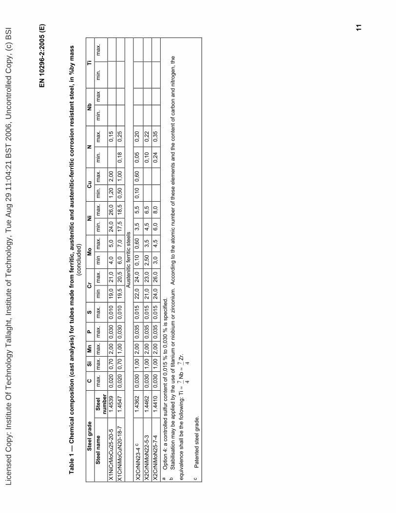
The European Committee for Standardisation (CEN) draws attention to the fact that it is claimed that compliance with this document may involve the use of patents applied to steel grades 1.4362 and 1.4854, the compositions of which are given in Tables 1 and 2.
CEN takes no position concerning the evidence, validity and scope of these patent rights.
The holders of these patent rights have assured CEN that they are willing to negotiate licences, under reasonable and non-discriminatory terms and conditions, with applicants throughout the world. In this respect, the statements of the holders of these patent rights are registered with CEN. Information may be obtained from: Grade 1.4362 Sandvik AB SE-811 81 SANDVIKEN Sweden Grade 1.4854 Outokumpu OYJ Intelectual Property Management P.O Box 27 FI – 02201 ESPOO Finland Attention is drawn to the possibility that some of the elements within this European Standard may be the subject of patent rights other than those indicated above. CEN shall not be responsible for identifying any or all such patent rights.
Lice
nsed
Cop
y: In
stitu
te O
f Tec
hnol
ogy
Tal
lagh
t, In
stitu
te o
f Tec
hnol
ogy,
Tue
Aug
29
11:0
4:21
BS
T 2
006,
Unc
ontr
olle
d C
opy,
(c)
BS
I

EN 10296-2:2005 (E)
5
1 Scope
This European Standard specifies the technical delivery conditions for welded tubes, of circular cross section, made from stainless steels, for mechanical and general engineering purposes.
2 Normative references
The following referenced documents are indispensable for the application of this document. For dated references, only the edition cited applies. For undated references, the latest edition of the referenced document (including any amendments) applies.
EN 910, Destructive tests on welds in metallic materials - Bend tests
EN 10002-1, Metallic materials – Tensile testing – Part 1: Method of test (at ambient temperature)
EN 10020:2000, Definition and classification of grades of steel
EN 10021:1993, General technical delivery requirements for steel and iron products
EN 10027-1, Designation systems for steel – Part 1: Steel names, principal symbols
EN 10027-2, Designation systems for steel – Part 2: Numerical system
EN 10052:1993, Vocabulary of heat treatment terms for ferrous products
EN 10088-1, Stainless steels – Part 1: List of stainless steels
EN 10168, Steel products – Inspection documents – List of information and description
EN 10204, Metallic products – Types of inspection documents
EN 10246-2, Non-destructive testing of steel tubes – Part 2: Automatic eddy current testing of seamless and welded (except submerged arc-welded) austenitic and austenitic-ferritic steel tubes for verification of hydraulic leak-tightness
EN 10246-3, Non-destructive testing of steel tubes – Part 3: Automatic eddy current testing of seamless and welded (except submerged arc-welded) steel tubes for the detection of imperfections
EN 10246-7, Non-destructive testing of steel tubes – Part 7: Automatic full peripheral ultrasonic testing of seamless and welded (except submerged arc-welded) steel tubes for the detection of longitudinal imperfections
EN 10246-8, Non-destructive testing of steel tubes – Part 8: Automatic ultrasonic testing of the weld seam of electric welded steel tubes for the detection of longitudinal imperfections
EN 10246-9, Non-destructive testing of steel tubes – Part 9: Automatic ultrasonic testing of the weld seam of submerged arc welded steel tubes for the detection of longitudinal and/or transverse imperfections
EN 10246-10, Non-destructive testing of steel tubes – Part 10: Radiographic testing of the weld seam of automatic fusion arc welded steel tubes for the detection of imperfections
EN 10256, Non-destructive testing of steel tubes – Qualification and competence of level 1 and 2 non-destructive testing personnel.
EN 10266:2003, Steel tubes, fittings and steel structural hollow sections - Symbols and definitions of terms for use in product standards.
CR 10260:1998, Designation system for steel – Additional symbols
Lice
nsed
Cop
y: In
stitu
te O
f Tec
hnol
ogy
Tal
lagh
t, In
stitu
te o
f Tec
hnol
ogy,
Tue
Aug
29
11:0
4:21
BS
T 2
006,
Unc
ontr
olle
d C
opy,
(c)
BS
I

EN 10296-2:2005 (E)
6
EN ISO 377, Steel and steel products – Location and preparation of samples and test pieces for mechanical testing (ISO 377:1997)
EN ISO 8491, Metallic materials – Tube (in full section) - Bend test (ISO 8491:1998)
EN ISO 8492, Metallic materials – Tube - Flattening test (ISO 8492:1998)
EN ISO 8493, Metallic materials – Tube - Drift expanding test (ISO 8493:1998)
EN ISO 8496, Metallic materials – Tube - Ring tensile test (ISO 8496:1998)
EN ISO 1127, Stainless steel tubes – Dimensions, tolerances and conventional masses per unit length (ISO 1127:1992).
EN ISO 2566-2, Steel – Conversion of elongation values – Part 2: Austenitic steels (ISO 2566-2:1984)
EN ISO 3651-2, Determination of resistance to intergranular corrosion of stainless steels – Part 2: Ferritic, austenitic and ferritic-austenitic (duplex) stainless steels – Corrosion test in media containing sulfuric acid (ISO 3651-2:1998)
3 Terms and definitions
For the purposes of this European Standard, the terms and definitions given in EN 10020:2000, EN 10021:1993, EN 10052:1993 and EN 10266:2003 together with the following apply.
employer organisation for which the person works on a regular basis
NOTE The employer may be either the tube manufacturer or a third party organisation providing non-destructive testing (NDT) services.
4 Symbols
For the purposes of this European Standard, the symbols given in EN 10266:2003 and CR 10260:1998 apply.
Not applicable.
5 Classification and designation
5.1 Classification
In accordance with the classification system in EN 10020, the steel grades listed in Tables 1 and 2 are stainless steels.
5.2 Designation
For tubes covered by this document the steel designation consists of:
number of this document (EN 10296-2);
plus either:
steel name in accordance with EN 10027-1 and CR 10260; or
steel number allocated in accordance with EN 10027-2.
Lice
nsed
Cop
y: In
stitu
te O
f Tec
hnol
ogy
Tal
lagh
t, In
stitu
te o
f Tec
hnol
ogy,
Tue
Aug
29
11:0
4:21
BS
T 2
006,
Unc
ontr
olle
d C
opy,
(c)
BS
I
EN 10296-2:2005 (E)
7
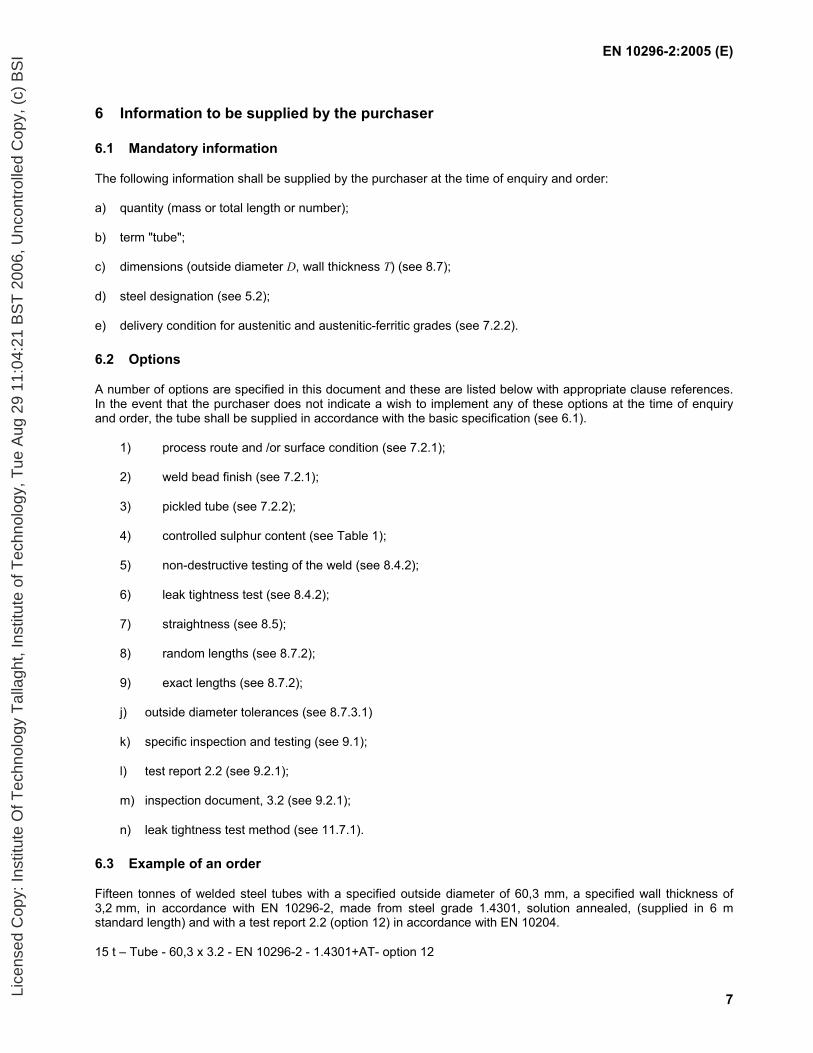
6 Information to be supplied by the purchaser
6.1 Mandatory information
The following information shall be supplied by the purchaser at the time of enquiry and order:
a) quantity (mass or total length or number);
b) term "tube";
c) dimensions (outside diameter D, wall thickness T) (see 8.7);
d) steel designation (see 5.2);
e) delivery condition for austenitic and austenitic-ferritic grades (see 7.2.2).
6.2 Options
A number of options are specified in this document and these are listed below with appropriate clause references. In the event that the purchaser does not indicate a wish to implement any of these options at the time of enquiry and order, the tube shall be supplied in accordance with the basic specification (see 6.1).
1) process route and /or surface condition (see 7.2.1);
2) weld bead finish (see 7.2.1);
3) pickled tube (see 7.2.2);
4) controlled sulphur content (see Table 1);
5) non-destructive testing of the weld (see 8.4.2);
6) leak tightness test (see 8.4.2);
7) straightness (see 8.5);
8) random lengths (see 8.7.2);
9) exact lengths (see 8.7.2);
j) outside diameter tolerances (see 8.7.3.1)
k) specific inspection and testing (see 9.1);
l) test report 2.2 (see 9.2.1);
m) inspection document, 3.2 (see 9.2.1);
n) leak tightness test method (see 11.7.1).
6.3 Example of an order
Fifteen tonnes of welded steel tubes with a specified outside diameter of 60,3 mm, a specified wall thickness of 3,2 mm, in accordance with EN 10296-2, made from steel grade 1.4301, solution annealed, (supplied in 6 m standard length) and with a test report 2.2 (option 12) in accordance with EN 10204.
15 t – Tube - 60,3 x 3.2 - EN 10296-2 - 1.4301+AT- option 12
Lice
nsed
Cop
y: In
stitu
te O
f Tec
hnol
ogy
Tal
lagh
t, In
stitu
te o
f Tec
hnol
ogy,
Tue
Aug
29
11:0
4:21
BS
T 2
006,
Unc
ontr
olle
d C
opy,
(c)
BS
I
EN 10296-2:2005 (E)
8
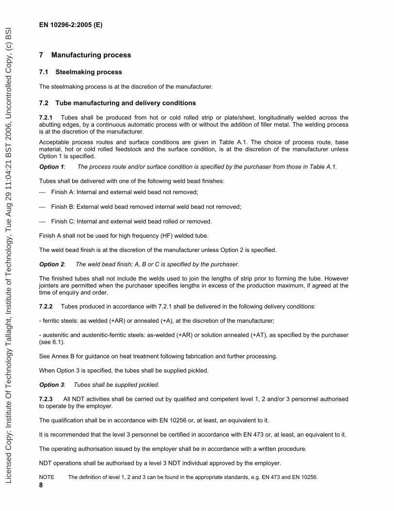
7 Manufacturing process
7.1 Steelmaking process
The steelmaking process is at the discretion of the manufacturer.
7.2 Tube manufacturing and delivery conditions
7.2.1 Tubes shall be produced from hot or cold rolled strip or plate/sheet, longitudinally welded across the abutting edges, by a continuous automatic process with or without the addition of filler metal. The welding process is at the discretion of the manufacturer.
Acceptable process routes and surface conditions are given in Table A.1. The choice of process route, base material, hot or cold rolled feedstock and the surface condition, is at the discretion of the manufacturer unless Option 1 is specified.
Option 1: The process route and/or surface condition is specified by the purchaser from those in Table A.1.
Tubes shall be delivered with one of the following weld bead finishes:
Finish A: Internal and external weld bead not removed;
Finish B: External weld bead removed internal weld bead not removed;
Finish C: Internal and external weld bead rolled or removed.
Finish A shall not be used for high frequency (HF) welded tube.
The weld bead finish is at the discretion of the manufacturer unless Option 2 is specified.
Option 2: The weld bead finish; A, B or C is specified by the purchaser.
The finished tubes shall not include the welds used to join the lengths of strip prior to forming the tube. However jointers are permitted when the purchaser specifies lengths in excess of the production maximum, if agreed at the time of enquiry and order. 7.2.2 Tubes produced in accordance with 7.2.1 shall be delivered in the following delivery conditions:
- ferritic steels: as welded (+AR) or annealed (+A), at the discretion of the manufacturer;
- austenitic and austenitic-ferritic steels: as-welded (+AR) or solution annealed (+AT), as specified by the purchaser (see 6.1).
See Annex B for guidance on heat treatment following fabrication and further processing.
When Option 3 is specified, the tubes shall be supplied pickled.
Option 3: Tubes shall be supplied pickled.
7.2.3 All NDT activities shall be carried out by qualified and competent level 1, 2 and/or 3 personnel authorised to operate by the employer.
The qualification shall be in accordance with EN 10256 or, at least, an equivalent to it.
It is recommended that the level 3 personnel be certified in accordance with EN 473 or, at least, an equivalent to it.
The operating authorisation issued by the employer shall be in accordance with a written procedure.
NDT operations shall be authorised by a level 3 NDT individual approved by the employer.
NOTE The definition of level 1, 2 and 3 can be found in the appropriate standards, e.g. EN 473 and EN 10256.
Lice
nsed
Cop
y: In
stitu
te O
f Tec
hnol
ogy
Tal
lagh
t, In
stitu
te o
f Tec
hnol
ogy,
Tue
Aug
29
11:0
4:21
BS
T 2
006,
Unc
ontr
olle
d C
opy,
(c)
BS
I
EN 10296-2:2005 (E)
9
8 Requirements
8.1 General
Tubes, when supplied in a delivery condition in accordance with 7.2.2, using a process route and to a surface condition given in Table A.1 and inspected in accordance with Clause 9, shall conform to the requirements of this document.
In addition, the general technical delivery requirements specified in EN 10021 shall apply.
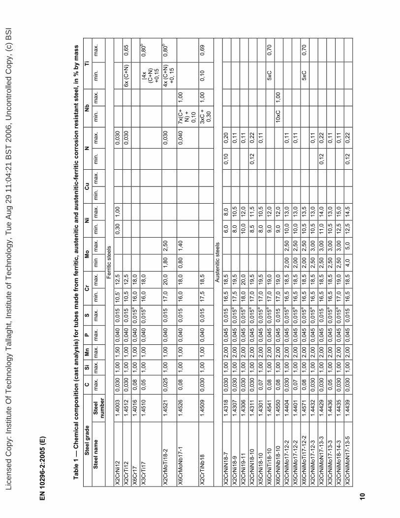
8.2 Chemical composition
The cast analysis reported by the steel producer shall apply and shall conform to the requirements of Tables 1 or 2, as appropriate.
Elements not included in Tables 1 and 2 shall not be intentionally added to the steel without the agreement of the purchaser, except for elements which may be added for finishing the cast. All appropriate measures shall be taken to prevent the addition of undesirable elements from scrap or other materials used in the steelmaking process.
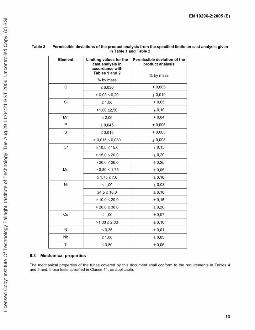
The permissible deviations of a product analysis from the specified limits of the cast analysis are given in Table 3.
NOTE When subsequently welding tubes produced according to this document, account should be taken of the fact that the behaviour of the steel during and after welding is dependent not only on the steel but also on the conditions of preparing for and carrying out the welding. Some of the steels specified in this standard cannot be welded unless specialised techniques are employed by specialist welders.
Lice
nsed
Cop
y: In
stitu
te O
f Tec
hnol
ogy
Tal
lagh
t, In
stitu
te o
f Tec
hnol
ogy,
Tue
Aug
29
11:0
4:21
BS
T 2
006,
Unc
ontr
olle
d C
opy,
(c)
BS
I
EN 1
0296
-2:2
005
(E)
10
Tabl
e 1
— C
hem
ical
com
posi
tion
(cas
t ana
lysi
s) fo
r tub
es m
ade
from
ferr
itic,
aus
teni
tic a
nd a
uste
nitic
-ferr
itic
corr
osio
n re
sist
ant s
teel
, in
% b
y m
ass
Stee
l gra
de
C
Si
Mn
P S
Cr
Mo
Ni
Cu
N
Nb
Ti
Stee
l nam
e St
eel
num
ber
max
. m
ax.
max
.m
ax.
max
. m
in.
max
.m
in
max
.m
in.
max
. m
in.
max
.m
in.
max
. m
in.
max
.m
in.
max
.
Ferr
itic
stee
ls
X2C
rNi1
2 1.
4003
0,
030
1,00
1,
500,
040
0,01
510
,5`
12,5
0,30
1,00
0,03
0
X2
CrT
i12
1.45
12
0,03
0 1,
00
1,00
0,04
00,
015
10,5
12,5
0,
030
6x (C
+N)
0,65
X6
Cr1
7 1.
4016
0,
08
1,00
1,
000,
040
0,01
5a16
,018
,0
X3
CrT
i17
1.45
10
0,05
1,
00
1,00
0,04
00,
015a
16,0
18,0
[4x
(C+N
) +0
,15
0,80
b
X2C
rMoT
i18-
2 1.
4521
0,
025
1,00
1,
000,
040
0,01
517
,020
,01,
802,
50
0,03
0
4x
(C+N
) +0
, 15
0,
80b
X6C
rMoN
b17-
1 1.
4526
0,
08
1,00
1,
000,
040
0,01
516
,018
,00,
801,
40
0,04
0 7x
(C+
N) +
0,
10
1,00
X2C
rTiN
b18
1.45
09
0,03
0 1,
00
1,00
0,04
00,
015
17,5
18,5
3xC
+
0,30
1,
000,
10
0,69
Aust
eniti
c st
eels
X2
CrN
iN18
-7
1.43
18
0,03
0 1,
00
2,00
0,04
50,
015
16,5
18,5
6,0
8,0
0,10
0,
20
X2C
rNi1
8-9
1.43
07
0,03
0 1,
00
2,00
0,04
50,
015a
17,5
19,5
8,0
10,5
0,11
X2
CrN
i19-
11
1.43
06
0,03
0 1,
00
2,00
0,04
50,
015a
18,0
20,0
10,0
12,0
0,11
X2
CrN
iN18
-10
1.43
11
0,03
0 1,
00
2,00
0,04
50,
015a
17,0
19,5
8,5
11,5
0,
12
0,22
X5
CrN
i18-
10
1.43
01
0,07
1,
00
2,00
0,04
50,
015a
17,0
19,5
8,0
10,5
0,11
X6
CrN
iTi1
8-10
1.
4541
0,
08
1,00
2,
000,
045
0,01
5a17
,019
,0
9,
0 12
,0
5xC
0,
70
X6C
rNiN
b18-
10
1.45
50
0,08
1,
00
2,00
0,04
50,
015
17,0
19,0
9,0
12,0
10
xC
1,00
X2C
rNiM
o17-
12-2
1.
4404
0,
030
1,00
2,
000,
045
0,01
5a16
,518
,52,
002,
5010
,013
,0
0,
11
X5C
rNiM
o17-
12-2
1.
4401
0,
07
1,00
2,
000,
045
0,01
5a16
,518
,52,
002,
5010
,013
,0
0,
11
X6C
rNiM
oTi1
7-12
-2
1.45
71
0,08
1,
00
2,00
0,04
50,
015a
16,5
18,5
2,00
2,50
10,5
13,5
5x
C
0,70
X2
CrN
iMo1
7-12
-3
1.44
32
0,03
0 1,
00
2,00
0,04
50,
015a
16,5
18,5
2,50
3,00
10,5
13,0
0,11
X2
CrN
iMoN
17-1
3-3
1.44
29
0,03
0 1,
00
2,00
0,04
50,
015
16,5
18,5
2,50
3,00
11,0
14,0
0,
12
0,22
X3
CrN
iMo1
7-13
-3
1.44
36
0,05
1,
00
2,00
0,04
50,
015a
16,5
18,5
2,50
3,00
10,5
13,0
0,11
X2
CrN
iMo1
8-14
-3
1.44
35
0,03
0 1,
00
2,00
0,04
50,
015a
17,0
19,0
2,50
3,00
12,5
15,0
0,11
X2
CrN
iMoN
17-1
3-5
1.44
39
0,03
0 1,
00
2,00
0,04
50,
015
16,5
18,5
4,0
5,0
12,5
14,5
0,
12
0,22
Lice
nsed
Cop
y: In
stitu
te O
f Tec
hnol
ogy
Tal
lagh
t, In
stitu
te o
f Tec
hnol
ogy,
Tue
Aug
29
11:0
4:21
BS
T 2
006,
Unc
ontr
olle
d C
opy,
(c)
BS
I
EN 1
0296
-2:2
005
(E)
11
Tabl
e 1
— C
hem
ical
com
posi
tion
(cas
t ana
lysi
s) fo
r tub
es m
ade
from
ferr
itic,
aus
teni
tic a
nd a
uste
nitic
-ferr
itic
corr
osio
n re
sist
ant s
teel
, in
%by
mas
s (c
oncl
uded
)
Stee
l gra
de
C
Si
Mn
P S
Cr
Mo
Ni
Cu
N
Nb
Ti
Stee
l nam
e St
eel
num
ber
max
. m
ax.
max
.m
ax.
max
. m
in
max
.m
in
max
.m
in.
max
. m
in.
max
.m
in.
max
. m
in.
max
min
. m
ax.
X1N
iCrM
oCu2
5-20
-5
1.45
39
0,02
0 0,
70
2,00
0,03
00,
010
19,0
21,0
4,0
5,0
24,0
26,0
1,
202,
00
0,15
X1
CrN
iMoC
uN20
-18-
7 1.
4547
0,
020
0,70
1,
000,
030
0,01
019
,520
,56,
0 7,
0 17
,518
,5
0,50
1,00
0,18
0,
25
Aus
teni
tic fe
rriti
c st
eels
X2C
rNiN
23-4
c
1.43
62
0,03
0 1,
00
2,00
0,03
50,
015
22,0
24,0
0,10
0,60
3,5
5,5
0,10
0,60
0,05
0,
20
X2C
rNiM
oN22
-5-3
1.
4462
0,
030
1,00
2,
000,
035
0,01
521
,023
,02,
503,
5 4,
5 6,
5
0,
10
0,22
X2
CrN
iMoN
25-7
-4
1.44
10
0,03
0 1,
00
2,00
0,03
50,
015
24,0
26,0
3,0
4,5
6,0
8,0
0,24
0,
35
a O
ptio
n 4:
a c
ontro
lled
sulfu
r con
tent
of 0
,015
% to
0,0
30 %
is s
peci
fied.
b
Sta
bilis
atio
n m
ay b
e ap
plie
d by
the
use
of ti
tani
um o
r nio
bium
or z
ircon
ium
. A
ccor
ding
to th
e at
omic
num
ber o
f the
se e
lem
ents
and
the
cont
ent o
f car
bon
and
nitro
gen,
the
equi
vale
nce
shal
l be
the
follo
win
g: T
i ≈ 47
Nb
≈ 47
Zr.
c Pa
tent
ed s
teel
gra
de.
Lice
nsed
Cop
y: In
stitu
te O
f Tec
hnol
ogy
Tal
lagh
t, In
stitu
te o
f Tec
hnol
ogy,
Tue
Aug
29
11:0
4:21
BS
T 2
006,
Unc
ontr
olle
d C
opy,
(c)
BS
I

EN 1
0296
-2:2
005
(E)
12
Tabl
e 2
— C
hem
ical
com
posi
tion
(Cas
t ana
lysi
s) fo
r tub
es m
ade
from
aus
teni
tic h
eat r
esis
ting
stee
l, in
% b
y m
ass
Stee
l gra
de
C
Si
Mn
P S
Cr
Ni
N
Ce
Stee
l nam
e St
eel
num
ber
min
. m
ax.
min
. m
ax.
max
. m
ax.
max
. m
in.
max
. m
in.
max
. m
in.
max
. m
in.
max
.
X15C
rNiS
i20-
12
1.48
28
0,
20
1,50
2,
50
2,00
0,
045
0,01
5 19
,0
21,0
11
,0
13,0
0,11
X9C
rNiS
iNC
e21-
11-2
1.
4835
0,
05
0,12
1,
40
2,50
1,
00
0,04
5 0,
015
20,0
22
,0
10,0
12
,0
0,12
0,
20
0,03
0,
08
X12C
rNi2
3-13
1.
4833
0,15
1,00
2,
00
0,04
5 0,
015
22,0
24
,0
12,0
14
,0
0,
11
X8C
rNi2
5-21
1.
4845
0,10
1,50
2,
00
0,04
5 0,
015
24,0
26
,0
19,0
22
,0
0,
11
X6C
rNiS
iNC
e19-
10
1.48
18
0,04
0,
08
1,00
2,
00
1,00
0,
045
0,01
5 18
,0
20,0
9,
0 11
,0
0,12
0,
20
0,03
0,
08
X6N
iCrS
iNC
e35-
25 a
1.
4854
0,
04
0,08
1,
20
2,00
2,
00
0,04
0 0,
015
24,0
26
,0
34,0
36
,0
0,12
0,
20
0,03
0,
08
a Pa
tent
ed s
teel
gra
de.
Lice
nsed
Cop
y: In
stitu
te O
f Tec
hnol
ogy
Tal
lagh
t, In
stitu
te o
f Tec
hnol
ogy,
Tue
Aug
29
11:0
4:21
BS
T 2
006,
Unc
ontr
olle
d C
opy,
(c)
BS
I
EN 10296-2:2005 (E)
13
Table 3 — Permissible deviations of the product analysis from the specified limits on cast analysis given in Table 1 and Table 2
Element Limiting values for the cast analysis in accordance with Tables 1 and 2
% by mass
Permissible deviation of the product analysis
% by mass
C ≤ 0,030 + 0,005
> 0,03 ≤ 0,20 ± 0,010
≤ 1,00 + 0,05 Si
>1,00 ≤2,50 ± 0,10
Mn ≤ 2,00 + 0,04
P ≤ 0,045 + 0,005
S ≤ 0,015 + 0,003
> 0,015 ≤ 0,030 ± 0,005
Cr ≥ 10,5 ≤ 15,0 ± 0,15
> 15,0 ≤ 20,0 ± 0,20
> 20,0 ≤ 26,0 ± 0,25
Mo > 0,80 < 1,75 ± 0,05
≥ 1,75 ≤ 7,0 ± 0,10
Ni ≤ 1,00 ± 0,03
≥4,5 ≤ 10,0 ± 0,10
> 10,0 ≤ 20,0 ± 0,15
> 20,0 ≤ 36,0 ± 0,20
≤ 1,00 ± 0,07 Cu
>1,00 ≤ 2,00 ± 0,10
N ≤ 0,35 ± 0,01
Nb ≤ 1,00 ± 0,05
Ti ≤ 0,80 ± 0,05
8.3 Mechanical properties
The mechanical properties of the tubes covered by this document shall conform to the requirements in Tables 4 and 5 and, those tests specified in Clause 11, as applicable.
Lice
nsed
Cop
y: In
stitu
te O
f Tec
hnol
ogy
Tal
lagh
t, In
stitu
te o
f Tec
hnol
ogy,
Tue
Aug
29
11:0
4:21
BS
T 2
006,
Unc
ontr
olle
d C
opy,
(c)
BS
I
EN 10296-2:2005 (E)
14
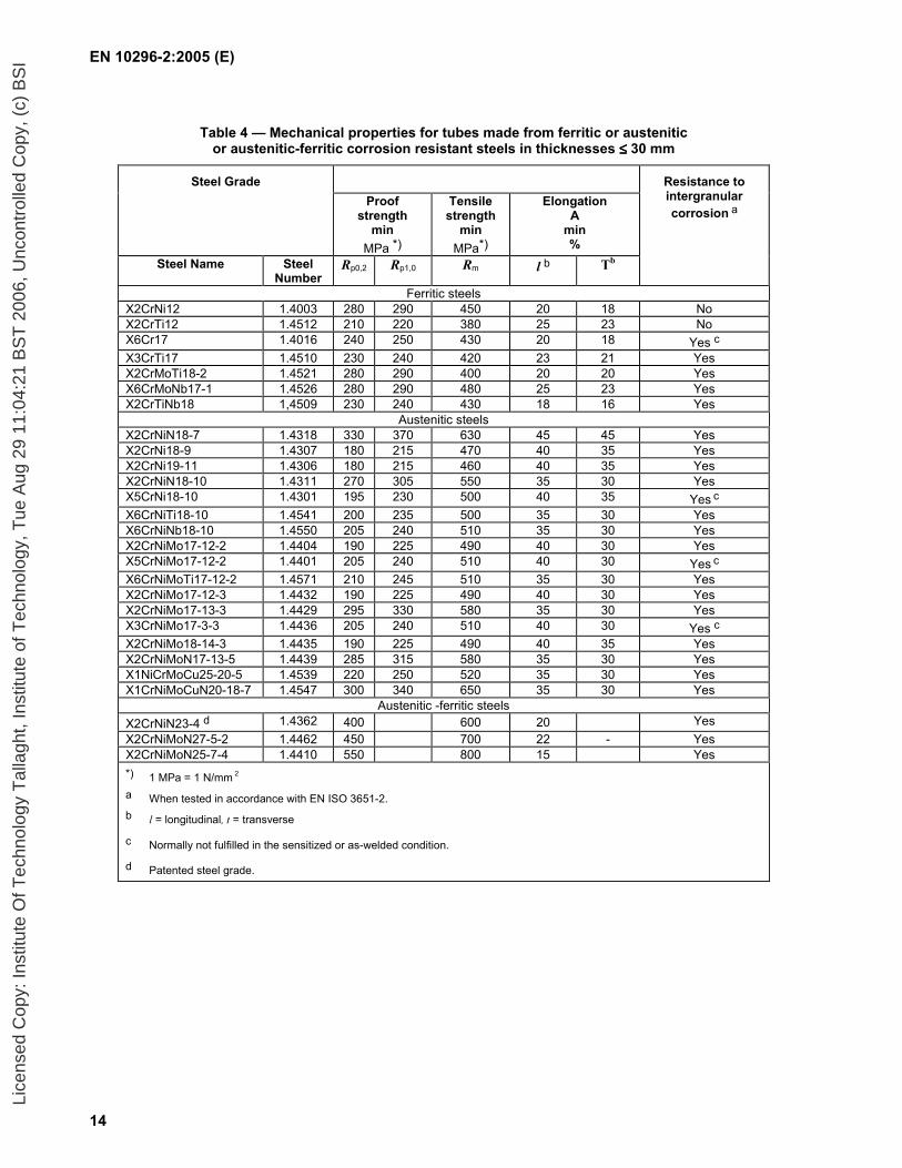
Table 4 — Mechanical properties for tubes made from ferritic or austenitic or austenitic-ferritic corrosion resistant steels in thicknesses ≤≤≤≤ 30 mm
Steel Grade Proof
strength min
MPa *)
Tensile strength
min MPa*)
Elongation A
min %
Resistance to intergranular corrosion a
Steel Name Steel Number
Rp0,2 Rp1,0 Rm l b Tb
Ferritic steels X2CrNi12 1.4003 280 290 450 20 18 No X2CrTi12 1.4512 210 220 380 25 23 No X6Cr17 1.4016 240 250 430 20 18 Yes c X3CrTi17 1.4510 230 240 420 23 21 Yes X2CrMoTi18-2 1.4521 280 290 400 20 20 Yes X6CrMoNb17-1 1.4526 280 290 480 25 23 Yes X2CrTiNb18 1,4509 230 240 430 18 16 Yes
Austenitic steels X2CrNiN18-7 1.4318 330 370 630 45 45 Yes X2CrNi18-9 1.4307 180 215 470 40 35 Yes X2CrNi19-11 1.4306 180 215 460 40 35 Yes X2CrNiN18-10 1.4311 270 305 550 35 30 Yes X5CrNi18-10 1.4301 195 230 500 40 35 Yes c X6CrNiTi18-10 1.4541 200 235 500 35 30 Yes X6CrNiNb18-10 1.4550 205 240 510 35 30 Yes X2CrNiMo17-12-2 1.4404 190 225 490 40 30 Yes X5CrNiMo17-12-2 1.4401 205 240 510 40 30 Yes c X6CrNiMoTi17-12-2 1.4571 210 245 510 35 30 Yes X2CrNiMo17-12-3 1.4432 190 225 490 40 30 Yes X2CrNiMo17-13-3 1.4429 295 330 580 35 30 Yes X3CrNiMo17-3-3 1.4436 205 240 510 40 30 Yes c X2CrNiMo18-14-3 1.4435 190 225 490 40 35 Yes X2CrNiMoN17-13-5 1.4439 285 315 580 35 30 Yes X1NiCrMoCu25-20-5 1.4539 220 250 520 35 30 Yes X1CrNiMoCuN20-18-7 1.4547 300 340 650 35 30 Yes
Austenitic -ferritic steels X2CrNiN23-4 d 1.4362 400 600 20 Yes X2CrNiMoN27-5-2 1.4462 450 700 22 - Yes X2CrNiMoN25-7-4 1.4410 550 800 15 Yes *) 1 MPa = 1 N/mm 2
a When tested in accordance with EN ISO 3651-2. b l = longitudinal, t = transverse
c Normally not fulfilled in the sensitized or as-welded condition.
d Patented steel grade.
Lice
nsed
Cop
y: In
stitu
te O
f Tec
hnol
ogy
Tal
lagh
t, In
stitu
te o
f Tec
hnol
ogy,
Tue
Aug
29
11:0
4:21
BS
T 2
006,
Unc
ontr
olle
d C
opy,
(c)
BS
I

EN 10296-2:2005 (E)
15
Table 5 — Mechanical properties for tubes made from austenitic heat resistant steels in the solution annealed (+AT) condition
Steel grade Proof strength
min
MPa *)
Tensile strength
min
MPa *
Elongation
A
min
%
Steel name Steel number
Rp 0,2 Rp 1,0 Rm l a b t a b
X15CrNiSi20-12 1.4828 230 270 550 30 30
X9CrNiSiNCe21-11-2 1.4835 310 350 650 40 40
X12CrNi23-13 1.4833 210 250 500 35 35
X8CrNi25-21 1.4845 210 250 500 35 35
X6CrNiSiNCe19-10 1.4818 290 330 600 40 40
X6NiCrSiNCe35-25 c 1.4854 300 340 650 40 40
* 1 MPa = 1 N/mm2
a l = longitudinal, t = transverse.
b Elongation 20% min for wall thickness ≤ 35 mm after cold deformation.
c Patented steel grade.
8.4 Appearance and soundness
8.4.1 Appearance
8.4.1.1 Tubes shall be free from external and internal surface defects that can be detected by visual examination.
8.4.1.2 The internal and external surface finish of the tubes shall be typical of the manufacturing process and, where applicable, the heat treatment employed. The finish and surface condition shall be such that any surface imperfections requiring dressing can be identified.
8.4.1.3 It shall be permissible to remove surface imperfections only by grinding or machining provided that, after so doing, the tube thickness in the dressed area is not less than the specified minimum wall thickness. All dressed areas shall blend smoothly into the contour of the tube.
8.4.1.4 Surface imperfections which encroach on the minimum wall thickness shall be considered defects and tubes containing these shall be deemed not to conform to this document.
8.4.1.5 For tubes with an outside diameter D greater than or equal to 114,3 mm, repair of the weld shall be permitted, provided that a compatible filler metal is used. Such weld repairs shall not exceed 20 % of the seam length.
The repair welding shall be carried out according to a written welding procedure specification (WPS).
The repaired tube shall conform to all the requirements of this document.
Lice
nsed
Cop
y: In
stitu
te O
f Tec
hnol
ogy
Tal
lagh
t, In
stitu
te o
f Tec
hnol
ogy,
Tue
Aug
29
11:0
4:21
BS
T 2
006,
Unc
ontr
olle
d C
opy,
(c)
BS
I

EN 10296-2:2005 (E)
16
8.4.2 Soundness
When Option 5 is specified, the seam weld of tubes supplied with specific inspection and testing shall be subjected to non-destructive testing.
Option 5 Non-destructive testing of the weld for the full length of each tube shall be carried out in accordance with 11.10.
When Option 6 is specified, tubes supplied with specific inspection and testing shall be subjected to a leak tightness test.
Option 6 Leak tightness testing of each tube shall be carried out in accordance with 11.7.
8.5 Straightness
For tubes with a specified outside diameter equal to or greater than 33,7 mm, the deviation from straightness over any tube length L, where L is the manufacturer’s delivered length, shall not exceed 0,0020 L, unless Option 7 is specified. For tubes with outside diameters less than 33,7 mm, the straightness and the method of measurement shall be agreed at the time of enquiry and order.
Option 7 The deviation from straightness shall not exceed 0,0015 L.
8.6 End preparation
Tubes shall be delivered with square cut ends. The ends shall be free from excessive burrs.
8.7 Dimensions, masses, lengths, tolerances and sectional properties
8.7.1 Outside diameter, wall thickness and mass
Outside diameters and wall thicknesses for tube covered by this document shall be as given in EN ISO 1127.
For calculation of mass, the densities given in EN 10088-1 shall apply.
NOTE Dimensions that are not included in EN ISO 1127 may be agreed at the time of enquiry and order.
8.7.2 Lengths
Tubes shall be supplied in a standard length of 6 000 mm, unless Options 8 or 9 are specified. For tolerances on length see 8.7.3.4.
NOTE Other lengths to a standard length tolerance may be available by agreement.
Option 8 Random lengths shall be supplied. The length range shall be agreed at the time of enquiry and order.
Option 9 Exact lengths shall be supplied. The length required shall be agreed at the time of enquiry and order.
8.7.3 Tolerances
8.7.3.1 Outside diameter
Unless Option 10 is specified, the tolerance on specified outside diameter, including ovality, shall be:
≤ 168,3 mm ± 0,75 % or ± 0,3 mm, whichever is the greater;
> 168,3 mm ± 1,0%.
Lice
nsed
Cop
y: In
stitu
te O
f Tec
hnol
ogy
Tal
lagh
t, In
stitu
te o
f Tec
hnol
ogy,
Tue
Aug
29
11:0
4:21
BS
T 2
006,
Unc
ontr
olle
d C
opy,
(c)
BS
I

EN 10296-2:2005 (E)
17
Option 10 Tubes of specified outside diameter ≤ 114,3 mm shall be supplied with a tolerance, including ovality, of ± 0,5 % or ± 0,15 mm, whichever is the greater.
8.7.3.2 Thickness
The tolerance on wall thickness, excluding the weld area, shall be ± 10 % or ± 0,2 mm, whichever is the greater.
8.7.3.3 Height of weld seam
The outside weld bead of HF welded tube shall be removed completely i.e. flush with the outside surface of the tube.
The maximum heights of the external and internal weld seams shall otherwise be as given in Table 6.
Table 6 — Maximum height of the weld seam
Dimensions in millimetres
Maximum height of the weld seam Weld finish
(see 7.2.1) T ≤≤≤≤ 8 T > 8
Finish A (0,20) T + 0,5 T /3
Finish B for D ≤ 114,3 mm (0,06) T +0,3 -
Finish B for D > 114,3 mm (0,05) T + 0,5 T /6
Finish C 0,15 -
8.7.3.4 Length
The tolerances on length shall be as given in Table 7.
Table 7 — Tolerances on length
Dimensions in millimetres
Type of length Length L
Tolerance
Standard 6 000 +100 0
Random Length range by agreement ≤ 6 000 +5
0
6 000 < L ≤ 12 000 +10 0
Exact
>12 000 0 / + by agreement
Lice
nsed
Cop
y: In
stitu
te O
f Tec
hnol
ogy
Tal
lagh
t, In
stitu
te o
f Tec
hnol
ogy,
Tue
Aug
29
11:0
4:21
BS
T 2
006,
Unc
ontr
olle
d C
opy,
(c)
BS
I
EN 10296-2:2005 (E)
18
8.7.4 Sectional properties
The nominal sectional properties shall be calculated in accordance with Annex C.
9 Inspection and testing
9.1 Types of inspection and testing
Conformity to the requirements of the order, for tubes supplied in accordance with this document, shall be checked by:
non-specific inspection and testing (see EN 10021), unless Option 11 is specified.
Option 11 Tubes shall be supplied with specific inspection and testing.
9.2 Inspection documents
9.2.1 Types of inspection documents
The following inspection documents, in accordance with EN 10204, shall be issued:
For tubes supplied with non-specific inspection and testing, a declaration of compliance with the order, 2.1, unless Option 12 is specified.
Option 12 A test report 2.2 shall be supplied.
For tubes supplied with specific inspection and testing, an inspection certificate, 3.1, unless Option 13 is specified.
Option 13 An inspection certificate 3.2 shall be supplied.
When an inspection certificate 3.2 is specified, the purchaser shall inform the manufacturer of the name and address of the organization or person nominated to carry out the inspection and testing and validate the certificate. It shall also be agreed which party shall issue the document.
9.2.2 Content of inspection documents
9.2.2.1 The contents of the inspection documents shall be in accordance with EN 10168 as shown in 9.2.2.2, 9.2.2.3 and 9.2.2.4.
9.2.2.2 For tubes supplied with non-specific inspection and testing, the declaration of compliance with the order, 2.1, shall contain the following codes and information:
A - Commercial transactions and parties involved;
B - Description of products to which the certificate of compliance applies;
Z - Validation.
9.2.2.3 For tubes supplied with non-specific inspection and testing and a test report 2.2, this shall contain the following codes and information:
A - Commercial transactions and parties involved;
B - Description of products to which the test report applies;
C02 - Direction of test pieces; Lice
nsed
Cop
y: In
stitu
te O
f Tec
hnol
ogy
Tal
lagh
t, In
stitu
te o
f Tec
hnol
ogy,
Tue
Aug
29
11:0
4:21
BS
T 2
006,
Unc
ontr
olle
d C
opy,
(c)
BS
I
EN 10296-2:2005 (E)
19
C10 — C13 - Tensile test;
C60 — C69 - Other tests (e.g. options invoked which require test pieces);
C71 — C92 - Chemical composition;
D01 - Marking and identification, surface appearance, shape and dimensional properties;
Z - Validation.
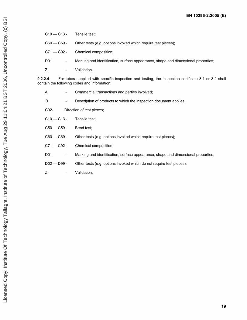
9.2.2.4 For tubes supplied with specific inspection and testing, the inspection certificate 3.1 or 3.2 shall contain the following codes and information:
A - Commercial transactions and parties involved;
B - Description of products to which the inspection document applies;
C02- Direction of test pieces;
C10 — C13 - Tensile test;
C50 — C59 - Bend test;
C60 — C69 - Other tests (e.g. options invoked which require test pieces);
C71 — C92 - Chemical composition;
D01 - Marking and identification, surface appearance, shape and dimensional properties;
D02 — D99 - Other tests (e.g. options invoked which do not require test pieces);
Z - Validation.
Lice
nsed
Cop
y: In
stitu
te O
f Tec
hnol
ogy
Tal
lagh
t, In
stitu
te o
f Tec
hnol
ogy,
Tue
Aug
29
11:0
4:21
BS
T 2
006,
Unc
ontr
olle
d C
opy,
(c)
BS
I

EN 10296-2:2005 (E)
20
9.3 Summary of inspection and testing
The requirements for inspection and testing are given in Table 8.
Table 8 — Requirements for inspection and testing
Types of inspection or test Non-specific inspection and
testing
Specific inspection and testing
Reference subclauses
Cast analysis Manufacturers procedure
1/cast 8.2
Tensile test Manufacturers procedure
1/test unit 8.3, 11.1
Flattening test a Manufacturers procedure
1/test unit 8.3, 11.2
Drift expanding test a b Manufacturers procedure
1/test unit 8.3, 11.3
Bend test (full tube section) a
Manufacturers procedure
1/test unit 8.3, 11.4
Ring tensile test c Manufacturers procedure
1/test unit 8.3, 11.5
Weld bend test c d Manufacturers procedure
1/test unit 8.3, 11.6
Dimensional inspection See 11.8
Visual examination See 11.9
Mandatory tests
Material identification individual individual 11.11
Optional tests Leak tightness test (Option 6)
Not applicable individual 8.4.2, 11.7
Non-destructive test of weld (Option 5)
Not applicable individual 8.4.2, 11.10
a The choice of flattening, drift expanding or bend test (full tube section) is at the discretion of the manufacturer.
NOTE The bend test (full tube section) is only applicable for outside diameters ≤ 65 mm. The flattening and drift expansion test are only applicable for outside diameters ≤ 150 mm.
b The test shall not be carried out on tubes with specified elongation values less than 15 %.
c The choice of ring tensile test or weld bend test is at the discretion of the manufacturer.
d One root and one face test.
10 Sampling
10.1 Frequency of tests
10.1.1 Test unit
In the case of specific inspection and testing, a test unit shall comprise tubes of the same specified diameter and wall thickness, the same steel grade, the same cast and the same process route, subjected to the same finishing treatment in a continuous furnace or heat treated in the same furnace charge in a batch-type furnace.
The maximum quantity of tubes per test unit shall be in accordance with Table 9.
Lice
nsed
Cop
y: In
stitu
te O
f Tec
hnol
ogy
Tal
lagh
t, In
stitu
te o
f Tec
hnol
ogy,
Tue
Aug
29
11:0
4:21
BS
T 2
006,
Unc
ontr
olle
d C
opy,
(c)
BS
I
EN 10296-2:2005 (E)
21
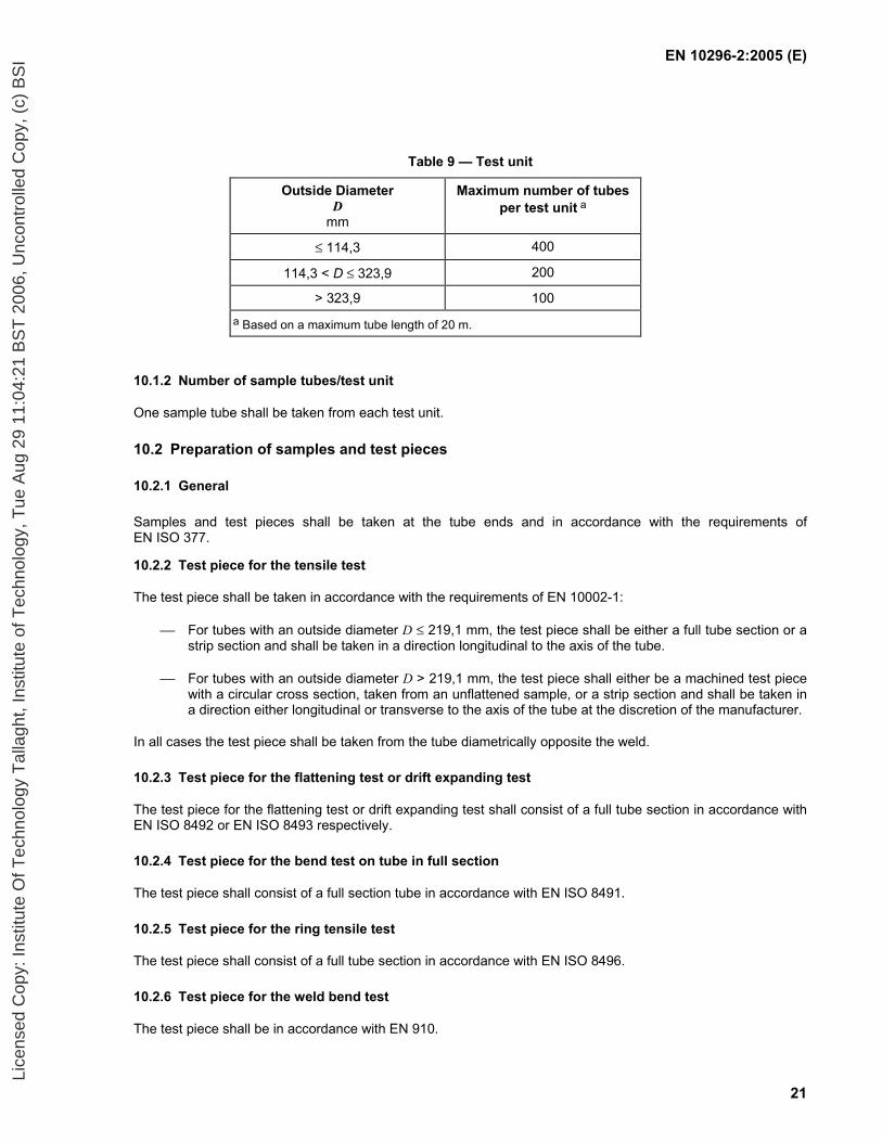
Table 9 — Test unit
Outside Diameter D
mm
Maximum number of tubes per test unit a
≤ 114,3 400
114,3 < D ≤ 323,9 200
> 323,9 100 a Based on a maximum tube length of 20 m.
10.1.2 Number of sample tubes/test unit
One sample tube shall be taken from each test unit.
10.2 Preparation of samples and test pieces
10.2.1 General
Samples and test pieces shall be taken at the tube ends and in accordance with the requirements of EN ISO 377.
10.2.2 Test piece for the tensile test
The test piece shall be taken in accordance with the requirements of EN 10002-1:
For tubes with an outside diameter D ≤ 219,1 mm, the test piece shall be either a full tube section or a strip section and shall be taken in a direction longitudinal to the axis of the tube.
For tubes with an outside diameter D > 219,1 mm, the test piece shall either be a machined test piece with a circular cross section, taken from an unflattened sample, or a strip section and shall be taken in a direction either longitudinal or transverse to the axis of the tube at the discretion of the manufacturer.
In all cases the test piece shall be taken from the tube diametrically opposite the weld.
10.2.3 Test piece for the flattening test or drift expanding test
The test piece for the flattening test or drift expanding test shall consist of a full tube section in accordance with EN ISO 8492 or EN ISO 8493 respectively.
10.2.4 Test piece for the bend test on tube in full section
The test piece shall consist of a full section tube in accordance with EN ISO 8491.
10.2.5 Test piece for the ring tensile test
The test piece shall consist of a full tube section in accordance with EN ISO 8496.
10.2.6 Test piece for the weld bend test
The test piece shall be in accordance with EN 910.
Lice
nsed
Cop
y: In
stitu
te O
f Tec
hnol
ogy
Tal
lagh
t, In
stitu
te o
f Tec
hnol
ogy,
Tue
Aug
29
11:0
4:21
BS
T 2
006,
Unc
ontr
olle
d C
opy,
(c)
BS
I
EN 10296-2:2005 (E)
22
11 Test methods
11.1 Tensile test
The test shall be carried out at room temperature in accordance with EN 10002-1 and the following determined:
tensile strength (Rm);
0,2% proof strength (Rp0,2) and, where applicable, the 1,0 % proof strength (Rp1,0);
percentage elongation after fracture with reference to a gauge length of 5,65 0S . If a non-proportional test piece is used, the percentage elongation value shall be converted to the value for a gauge length L0 =
5,65 0S using the conversion tables given in EN ISO 2566-2.
11.2 Flattening test
The test shall be carried out in accordance with EN ISO 8492 with the weld placed at 90° to the direction of flattening. The tube section shall be flattened in a press until the distance between the platens reaches 67 % of the original outside diameter. After testing, the test piece shall be free from cracks or breaks, however, slight incipient cracking at the edges shall not be regarded as cause for rejection.
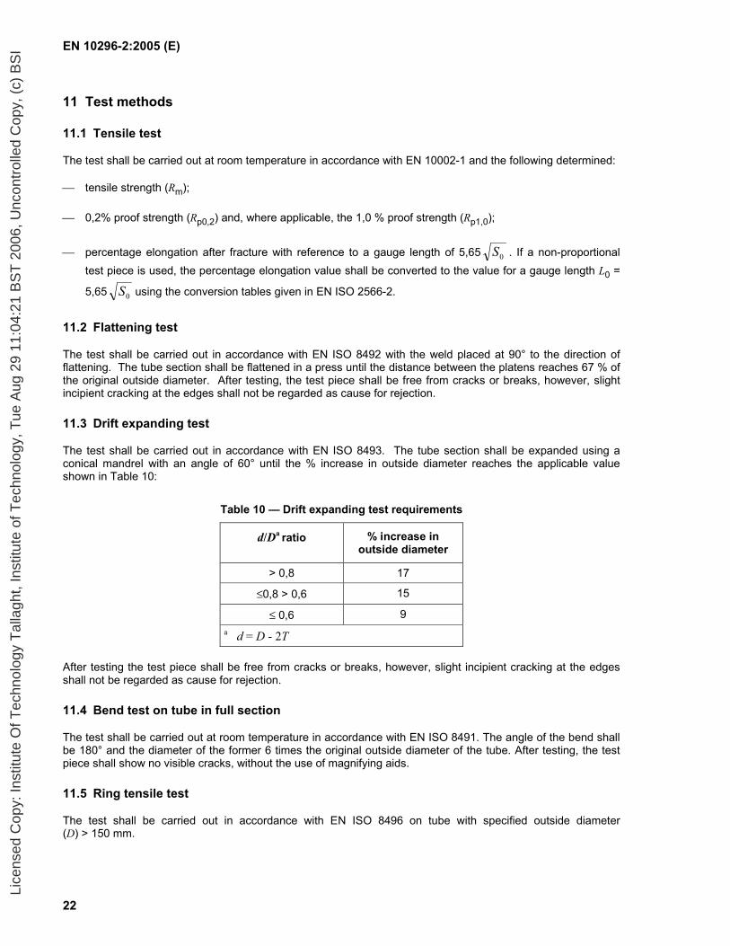
11.3 Drift expanding test
The test shall be carried out in accordance with EN ISO 8493. The tube section shall be expanded using a conical mandrel with an angle of 60° until the % increase in outside diameter reaches the applicable value shown in Table 10:
Table 10 — Drift expanding test requirements
d/Da ratio % increase in outside diameter
> 0,8 17
≤0,8 > 0,6 15
≤ 0,6 9 a d = D - 2T
After testing the test piece shall be free from cracks or breaks, however, slight incipient cracking at the edges shall not be regarded as cause for rejection.
11.4 Bend test on tube in full section
The test shall be carried out at room temperature in accordance with EN ISO 8491. The angle of the bend shall be 180° and the diameter of the former 6 times the original outside diameter of the tube. After testing, the test piece shall show no visible cracks, without the use of magnifying aids.
11.5 Ring tensile test
The test shall be carried out in accordance with EN ISO 8496 on tube with specified outside diameter (D) > 150 mm.
Lice
nsed
Cop
y: In
stitu
te O
f Tec
hnol
ogy
Tal
lagh
t, In
stitu
te o
f Tec
hnol
ogy,
Tue
Aug
29
11:0
4:21
BS
T 2
006,
Unc
ontr
olle
d C
opy,
(c)
BS
I
EN 10296-2:2005 (E)
23
11.6 Weld bend test
The tests shall be carried out in accordance with EN 910 on tube with specified outside diameter (D) > 150 mm using a mandrel of diameter 6 T. One test shall be a root bend test and the other a face bend test. After testing, the test piece shall show no cracks or flaws, however imperfections less than 3 mm long on the specimen edges shall not be regarded as a cause for failure of the test.
11.7 Leak tightness test
11.7.1 General
When Option 6 is specified ERW and laser beam welded tubes shall be leak tightness tested in accordance with 11.7.2 or 11.7.3. The choice of test method shall be at the discretion of the manufacturer unless Option 14 is specified.
Option 14: The test method for verification of the leak tightness of tubes according to 11.7.2 or 11.7.3 shall be chosen by the purchaser.
Submerged arc-welded tubes shall be tested in accordance with 11.7.3.
11.7.2 Electromagnetic test
The test shall be carried out in accordance with EN 10246-2.
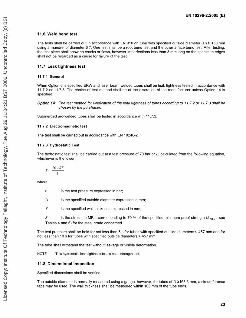
11.7.3 Hydrostatic Test
The hydrostatic test shall be carried out at a test pressure of 70 bar or P, calculated from the following equation, whichever is the lower.
DSTP ×= 20
where
P is the test pressure expressed in bar;
D is the specified outside diameter expressed in mm;
T is the specified wall thickness expressed in mm;
S is the stress, in MPa, corresponding to 70 % of the specified minimum proof strength (Rp0,2 - see Tables 4 and 5) for the steel grade concerned.
The test pressure shall be held for not less than 5 s for tubes with specified outside diameters ≤ 457 mm and for not less than 10 s for tubes with specified outside diameters > 457 mm.
The tube shall withstand the test without leakage or visible deformation.
NOTE This hydrostatic leak tightness test is not a strength test.
11.8 Dimensional inspection
Specified dimensions shall be verified.
The outside diameter is normally measured using a gauge, however, for tubes of D ≥168,3 mm, a circumference tape may be used. The wall thickness shall be measured within 100 mm of the tube ends.
Lice
nsed
Cop
y: In
stitu
te O
f Tec
hnol
ogy
Tal
lagh
t, In
stitu
te o
f Tec
hnol
ogy,
Tue
Aug
29
11:0
4:21
BS
T 2
006,
Unc
ontr
olle
d C
opy,
(c)
BS
I

EN 10296-2:2005 (E)
24
11.9 Visual examination
Tubes shall be visually examined to ensure compliance with the requirements of 8.4.1.
11.10 Non-destructive testing of the weld
When Option 5 is specified testing should be carried out in accordance with one of the following non-destructive testing standards to the acceptance level indicated. The calibration shall be carried out using only an external reference notch or, as an alternative for eddy current testing, a hole:
EN 10246-3 - acceptance level E3 or E3H;
NOTE Only for tubes of wall thickness ≤ 6 mm.
EN 10246-7 - acceptance level U4;
EN 10246-8 - acceptance level U4;
EN 10246-9 - acceptance level U4.
— EN 10246-10 - image quality class R2, except that radioscopic methods, whose sensitivity can be demonstrated to be equivalent, are permitted at the discretion of the manufacturer.
The choice of test method, as appropriate for the type of tube, is at the discretion of the manufacturer.
11.11 Material identification
Each tube shall be tested by an appropriate method to ensure that the correct grade is being supplied.
11.12 Retests, sorting and reprocessing
For retests, sorting and reprocessing the requirements of EN 10021 shall apply.
12 Marking
12.1 General
Except as provided for in 12.2 for tubes which are supplied bundled, each tube shall be marked, by suitable and durable methods such as ink spraying, stamping, adhesive labels or attached tags, with the following information:
manufacturer’s name or trademark;
dimensions;
steel designation;
cast number or code number;
symbol for the delivery condition, e.g. +AR where applicable;
in the case of specific inspection:
mark of the inspection representative;
identification number (e.g. order or item number) which permits the correlation of the product or delivery unit to the related document
Lice
nsed
Cop
y: In
stitu
te O
f Tec
hnol
ogy
Tal
lagh
t, In
stitu
te o
f Tec
hnol
ogy,
Tue
Aug
29
11:0
4:21
BS
T 2
006,
Unc
ontr
olle
d C
opy,
(c)
BS
I

EN 10296-2:2005 (E)
25
and at the discretion of the manufacturer:
symbol for the process route and surface condition, where applicable (see Option 1 and Table A.1).
EXAMPLE OF MARKING
X - 48,3 x 3,6 -EN 10296-2 - 1.4301 – C - - Y - Z
where
X is the manufacturer’s name or trademark;
C is the cast number or code number;
Y is the mark of inspection representative;
Z is the identification number (e.g. order or item number).
12.2 Bundles
Where the products are supplied bundled, the marking required in 12.1 may be on a label which shall be securely attached to the bundle.
13 Handling and packaging
Tubes shall be protected from carbon steel strapping which shall not be allowed to come into contact with the tubes.
Special measures to protect the tube during delivery or storage may be agreed between the purchaser and manufacturer at the time of enquiry and order.
Lice
nsed
Cop
y: In
stitu
te O
f Tec
hnol
ogy
Tal
lagh
t, In
stitu
te o
f Tec
hnol
ogy,
Tue
Aug
29
11:0
4:21
BS
T 2
006,
Unc
ontr
olle
d C
opy,
(c)
BS
I
EN 10296-2:2005 (E)
26
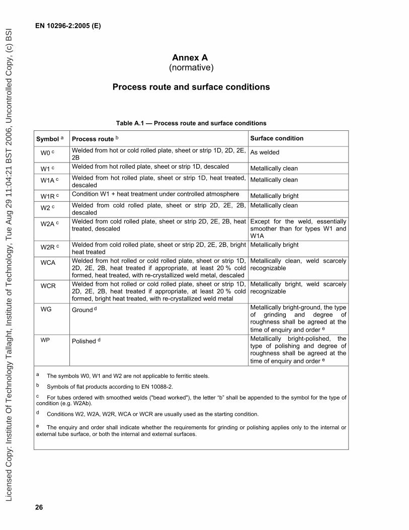
Annex A (normative)
Process route and surface conditions
Table A.1 — Process route and surface conditions
Symbol a Process route b Surface condition
W0 c Welded from hot or cold rolled plate, sheet or strip 1D, 2D, 2E, 2B
As welded
W1 c Welded from hot rolled plate, sheet or strip 1D, descaled Metallically clean
W1A c Welded from hot rolled plate, sheet or strip 1D, heat treated, descaled
Metallically clean
W1R c Condition W1 + heat treatment under controlled atmosphere Metallically bright
W2 c Welded from cold rolled plate, sheet or strip 2D, 2E, 2B, descaled
Metallically clean
W2A c Welded from cold rolled plate, sheet or strip 2D, 2E, 2B, heat treated, descaled
Except for the weld, essentially smoother than for types W1 and W1A
W2R c Welded from cold rolled plate, sheet or strip 2D, 2E, 2B, bright heat treated
Metallically bright
WCA Welded from hot rolled or cold rolled plate, sheet or strip 1D, 2D, 2E, 2B, heat treated if appropriate, at least 20 % cold formed, heat treated, with re-crystallized weld metal, descaled
Metallically clean, weld scarcely recognizable
WCR Welded from hot rolled or cold rolled plate, sheet or strip 1D, 2D, 2E, 2B, heat treated if appropriate, at least 20 % cold formed, bright heat treated, with re-crystallized weld metal
Metallically bright, weld scarcely recognizable
WG Ground d Metallically bright-ground, the type of grinding and degree of roughness shall be agreed at the time of enquiry and order e
WP Polished d Metallically bright-polished, the type of polishing and degree of roughness shall be agreed at the time of enquiry and order e
a The symbols W0, W1 and W2 are not applicable to ferritic steels.
b Symbols of flat products according to EN 10088-2. c For tubes ordered with smoothed welds ("bead worked"), the letter “b” shall be appended to the symbol for the type of condition (e.g. W2Ab). d Conditions W2, W2A, W2R, WCA or WCR are usually used as the starting condition.
e The enquiry and order shall indicate whether the requirements for grinding or polishing applies only to the internal or external tube surface, or both the internal and external surfaces.
Lice
nsed
Cop
y: In
stitu
te O
f Tec
hnol
ogy
Tal
lagh
t, In
stitu
te o
f Tec
hnol
ogy,
Tue
Aug
29
11:0
4:21
BS
T 2
006,
Unc
ontr
olle
d C
opy,
(c)
BS
I

EN 10296-2:2005 (E)
27
Annex B (informative)
Guideline data on heat treatment during fabrication and hot working as
part of further processing
Table B.1 — Guideline data for ferritic corrosion resistant steels a
Steel grade Heat treatment during fabrication and further processing
Hot working during further processing e.g. hot bending
Steel name Steel number
Annealing temperature Type of cooling
Temperature °°°°C
Type of cooling
X2CrNi12 1.4003 700 to 750 water or air or gas 1 100 to 800 Air or gas
X2CrTi12 1.4512 750 to 850 water or air or gas 1 100 to 800 Air or gas
X6Cr17 1.4016 750 to 850 water or air or gas 1 100 to 800 Air or gas
X3CrTi17 1.4510 750 to 850 water or air or gas 1 100 to 800 Air or gas
X2CrMoTi18-2 1.4521 820 to 880 water or air or gas 1 100 to 800 Air or gas
X6CrMoNb17-1 1.4526 820 to 880 water or air or gas 1 100 to 800 Air or gas
X2CrTiNb18 1.4509 870 to 930 water or air or gas 1 100 to 800 Air or gas a In special cases furnace cooling is also permitted.
Table B.2 — Guideline data for austenitic and austenitic-ferritic corrosion resistant steels
Steel grade Heat treatment during fabrication and further processing
Hot working during further processing e.g. Hot
bending
Steel name Steel number
Solution annealing temperature a
°°°°C
Type of cooling b Temperature °°°°C
Type of cooling
Austenitic steels
X2CrNiN18-7 1.4318 1 020 to 1 100 Quenching in water or air or gas
1 150 to 850 Air or gas
X2CrNi18-9 1.4307 1 000 to 1 100 Quenching in water or air or gas
1 150 to 850 Air or gas
X2CrNi19-11 1.4306 1 000 to 1 100 Quenching in water or air or gas
1 150 to 850 Air or gas
X2CrNiN18-10 1.4311 1 000 to 1 100 Quenching in water or air or gas
1 150 to 850 Air or gas
X5CrNi18-10 1.4301 1 000 to 1 100 Quenching in water or air or
1 150 to 750 Air or gas
X6CrNiTi18-10 1.4541 1 000 to 1 100 Quenching in water or air or gas
1 150 to 850 Air or gas
X6CrNiNb18-10 1.4550 1 020 to 1 100 Quenching in water or air or gas
1 150 to 850 Air or gas
Lice
nsed
Cop
y: In
stitu
te O
f Tec
hnol
ogy
Tal
lagh
t, In
stitu
te o
f Tec
hnol
ogy,
Tue
Aug
29
11:0
4:21
BS
T 2
006,
Unc
ontr
olle
d C
opy,
(c)
BS
I
EN 10296-2:2005 (E)
28
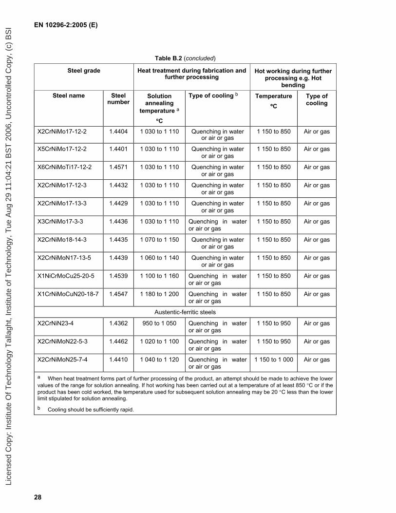
Table B.2 (concluded)
Steel grade Heat treatment during fabrication and further processing
Hot working during further processing e.g. Hot
bending
Steel name Steel number
Solution annealing
temperature a
°°°°C
Type of cooling b Temperature °°°°C
Type of cooling
X2CrNiMo17-12-2 1.4404 1 030 to 1 110 Quenching in water or air or gas
1 150 to 850 Air or gas
X5CrNiMo17-12-2 1.4401 1 030 to 1 110 Quenching in water or air or gas
1 150 to 850 Air or gas
X6CrNiMoTi17-12-2 1.4571 1 030 to 1 110 Quenching in water or air or gas
1 150 to 850 Air or gas
X2CrNiMo17-12-3 1.4432 1 030 to 1 110 Quenching in water or air or gas
1 150 to 850 Air or gas
X2CrNiMo17-13-3 1.4429 1 030 to 1 110 Quenching in water or air or gas
1 150 to 850 Air or gas
X3CrNiMo17-3-3 1.4436 1 030 to 1 110 Quenching in water or air or gas
1 150 to 850 Air or gas
X2CrNiMo18-14-3 1.4435 1 070 to 1 150 Quenching in water or air or gas
1 150 to 850 Air or gas
X2CrNiMoN17-13-5 1.4439 1 060 to 1 140 Quenching in water or air or gas
1 150 to 850 Air or gas
X1NiCrMoCu25-20-5 1.4539 1 100 to 1 160 Quenching in water or air or gas
1 150 to 850 Air or gas
X1CrNiMoCuN20-18-7 1.4547 1 180 to 1 200 Quenching in water or air or gas
1 150 to 850 Air or gas
Austentic-ferritic steels
X2CrNiN23-4 1.4362 950 to 1 050 Quenching in water or air or gas
1 150 to 950 Air or gas
X2CrNiMoN22-5-3 1.4462 1 020 to 1 100 Quenching in water or air or gas
1 150 to 950 Air or gas
X2CrNiMoN25-7-4 1.4410 1 040 to 1 120 Quenching in water or air or gas
1 150 to 1 000 Air or gas
a When heat treatment forms part of further processing of the product, an attempt should be made to achieve the lower values of the range for solution annealing. If hot working has been carried out at a temperature of at least 850 °C or if the product has been cold worked, the temperature used for subsequent solution annealing may be 20 °C less than the lower limit stipulated for solution annealing.
b Cooling should be sufficiently rapid.
Lice
nsed
Cop
y: In
stitu
te O
f Tec
hnol
ogy
Tal
lagh
t, In
stitu
te o
f Tec
hnol
ogy,
Tue
Aug
29
11:0
4:21
BS
T 2
006,
Unc
ontr
olle
d C
opy,
(c)
BS
I

EN 10296-2:2005 (E)
29
Table B.3 —Guideline data for austenitic heat resisting stainless steels
Steel grade Heat treatment Hot working during further processing e.g. hot bending
Steel name Steel number Temperature
°°°°C
Type of cooling
a Temperature
°°°°C
Type of cooling
X15CrNiSi20-12 1.4828 1 050 to 1 150 Quenching in water, air or gas
1 150 to 850 Air or gas
X9CrNiSiNCe21-11-2 1.4835 1 020 to 1 120 Quenching in water, air or gas
1 100 to 850 Air or gas
X12CrNi23-13 1.4833 1 050 to 1 150 Quenching in water, air or gas
1 100 to 850 Air or gas
X8CrNi25-21 1.4845 1 050 to 1 150 Quenching in water, air or gas
1 100 to 850 Air or gas
X6CrNiSiNCe19-10 1.4818 1 020 to 1 120 Quenching in water, air or gas
1 100 to 850 Air or gas
X6NiCrSiNCe35-25 1.4854 1 100 to 1 150 Quenching in water, air or gas
1 100 to 850 Air or gas
a Cooling should be sufficiently rapid.
Lice
nsed
Cop
y: In
stitu
te O
f Tec
hnol
ogy
Tal
lagh
t, In
stitu
te o
f Tec
hnol
ogy,
Tue
Aug
29
11:0
4:21
BS
T 2
006,
Unc
ontr
olle
d C
opy,
(c)
BS
I

EN 10296-2:2005 (E)
30
Annex C (normative)
Formulae for calculation of nominal sectional properties
The nominal sectional properties for tubes are calculated from the following geometric properties using the formulae given below:
Specified outside diameter D (mm)
Specified thickness T (mm)
Calculated inside diameter d = D - 2T (mm)
Superficial area/unit length As =
310
Dπ (m2/m)
Cross sectional area A = 2
22
104)(
×
−π dD (cm2)
Mass per unit length M = ρA
where ρ is the density of the steel in accordance with EN 10088-1
(kg/m)
Second moment of area I =
4
44
1064
)(
×
−π dD (cm4)
Radius of gyration i =
AI (cm)
Elastic section modulus Wel = D
I 102 × (cm3)
Plastic section modulus Wpl =
3
33
106×
− dD (cm3)
Torsional inertia constant (polar moment of inertia) It = 2 I (cm4)
Torsional modulus constant Ct = 2 Wel (cm3)
Lice
nsed
Cop
y: In
stitu
te O
f Tec
hnol
ogy
Tal
lagh
t, In
stitu
te o
f Tec
hnol
ogy,
Tue
Aug
29
11:0
4:21
BS
T 2
006,
Unc
ontr
olle
d C
opy,
(c)
BS
I
EN 10296-2:2005 (E)
31
Bibliography
[1] EN 473, Non-destructive testing - Qualification and certification of NDT personnel - General principles.
[2] EN 10088-2, Stainless steels - Part 2: Technical delivery conditions for sheet/plate and strip for general purposes
Lice
nsed
Cop
y: In
stitu
te O
f Tec
hnol
ogy
Tal
lagh
t, In
stitu
te o
f Tec
hnol
ogy,
Tue
Aug
29
11:0
4:21
BS
T 2
006,
Unc
ontr
olle
d C
opy,
(c)
BS
I

BS EN 10296-2:2005
BSI
389 Chiswick High Road
London
W4 4AL
BSI — British Standards InstitutionBSI is the independent national body responsible for preparing British Standards. It presents the UK view on standards in Europe and at the international level. It is incorporated by Royal Charter.
Revisions
British Standards are updated by amendment or revision. Users of British Standards should make sure that they possess the latest amendments or editions.
It is the constant aim of BSI to improve the quality of our products and services. We would be grateful if anyone finding an inaccuracy or ambiguity while using this British Standard would inform the Secretary of the technical committee responsible, the identity of which can be found on the inside front cover. Tel: +44 (0)20 8996 9000. Fax: +44 (0)20 8996 7400.
BSI offers members an individual updating service called PLUS which ensures that subscribers automatically receive the latest editions of standards.
Buying standards
Orders for all BSI, international and foreign standards publications should be addressed to Customer Services. Tel: +44 (0)20 8996 9001. Fax: +44 (0)20 8996 7001. Email: [email protected]. Standards are also available from the BSI website at http://www.bsi-global.com.
In response to orders for international standards, it is BSI policy to supply the BSI implementation of those that have been published as British Standards, unless otherwise requested.
Information on standards
BSI provides a wide range of information on national, European and international standards through its Library and its Technical Help to Exporters Service. Various BSI electronic information services are also available which give details on all its products and services. Contact the Information Centre. Tel: +44 (0)20 8996 7111. Fax: +44 (0)20 8996 7048. Email: [email protected].
Subscribing members of BSI are kept up to date with standards developments and receive substantial discounts on the purchase price of standards. For details of these and other benefits contact Membership Administration. Tel: +44 (0)20 8996 7002. Fax: +44 (0)20 8996 7001. Email: [email protected].
Information regarding online access to British Standards via British Standards Online can be found at http://www.bsi-global.com/bsonline.
Further information about BSI is available on the BSI website at http://www.bsi-global.com.
Copyright
Copyright subsists in all BSI publications. BSI also holds the copyright, in the UK, of the publications of the international standardization bodies. Except as permitted under the Copyright, Designs and Patents Act 1988 no extract may be reproduced, stored in a retrieval system or transmitted in any form or by any means – electronic, photocopying, recording or otherwise – without prior written permission from BSI.
This does not preclude the free use, in the course of implementing the standard, of necessary details such as symbols, and size, type or grade designations. If these details are to be used for any other purpose than implementation then the prior written permission of BSI must be obtained.
Details and advice can be obtained from the Copyright & Licensing Manager. Tel: +44 (0)20 8996 7070. Fax: +44 (0)20 8996 7553. Email: [email protected].
Lice
nsed
Cop
y: In
stitu
te O
f Tec
hnol
ogy
Tal
lagh
t, In
stitu
te o
f Tec
hnol
ogy,
Tue
Aug
29
11:0
4:21
BS
T 2
006,
Unc
ontr
olle
d C
opy,
(c)
BS
I