Embed Size (px)
Citation preview
Web Tension Units
FMU-1, FMU-5 and PST-2
Installation instructions
GB

Web Tension Units
INDEX:
1. GENERAL
2. KIS/KISD LOAD CELL CONCEPT AND BENEFITS
3. PRINCIPLE OF THE FMU-1 AND FMU-5
4. POSITIONING OF THE WEB TENSION UNIT
5. INSTALLATION AND COMMISSIONING OF THE FMU-1 AND FMU-5
6. PRINCIPLE OF THE PST-2
7. INSTALLATION AND COMMISSIONING OF THE PST-2
8. CALIBRATION OF WEB TENSION UNIT

Installation Instructions

Web Tension Units
1
1. GENERAL The web tension unit type FMU-1 and FMU-5 has been specially designed for measuring the tension forces on paper machines or on steel strips in steel industry. FMU-1 is made for capacities 2 kN - 200 kN and FMU-5 for 100 kN – 2000 kN.
The web tension unit FMU-1 consists of two standard pins KIS load cells and one special mechanical assembly made for customer application in order to fit as well as possible to the existing mechanical installation.
The web tension unit FMU-5 consists of two standard pins KISD load cells and one special mechanical assembly also made for customer application.
The PST-2 web tension unit is mainly constructed for tension measurement on steel furnace for galvanizing and annealed lines where axial forces on the rollers due to thermal expansions, can be of great affect. The PST-2 are available in capacities 20 kN - 200 kN. The PST-2 consists of four standard pins KIS load cells and one special mechanical assembly made for customer application.
The electrical outputs of the KIS/KISD load cells are directly proportional to the force applied on the measuring roll, and therefore proportional to the tension applied on the paper, felt or steel strip.
For an easy application, it will be more simple to use fixed wrap angle on the measuring roll, in order to have a measurement of the tension force directly proportional to the applied resultant force on the measuring roll. If the wrap angle on the measuring roll is not fixed (winders or re-winders for example), a sinus or cosines function will be needed (in a PLC or a calculator) in order to have a resultant force on the measuring roll directly proportional to the tension force applied on the roller and the wrap angle variations.
Installation Instructions
2
2. KIS/KISD LOAD CELL CONCEPT AND BENEFITS
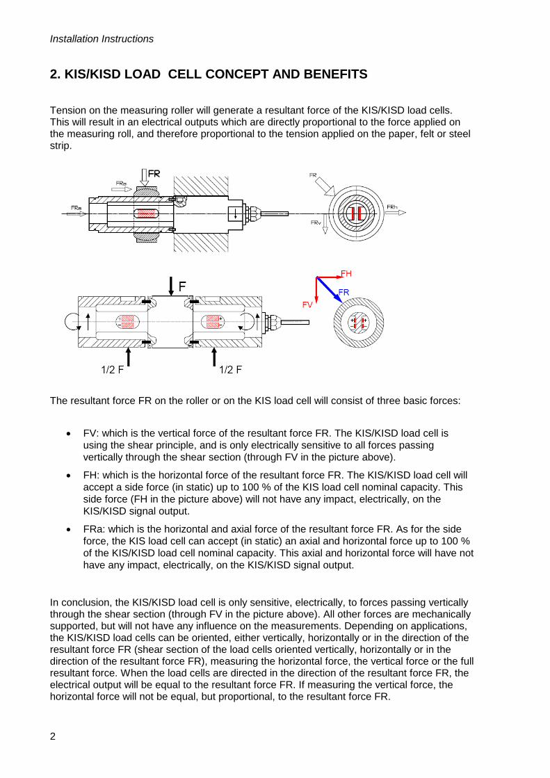
Tension on the measuring roller will generate a resultant force of the KIS/KISD load cells. This will result in an electrical outputs which are directly proportional to the force applied on the measuring roll, and therefore proportional to the tension applied on the paper, felt or steel strip.
The resultant force FR on the roller or on the KIS load cell will consist of three basic forces:
• FV: which is the vertical force of the resultant force FR. The KIS/KISD load cell is
using the shear principle, and is only electrically sensitive to all forces passing vertically through the shear section (through FV in the picture above).
• FH: which is the horizontal force of the resultant force FR. The KIS/KISD load cell will accept a side force (in static) up to 100 % of the KIS load cell nominal capacity. This side force (FH in the picture above) will not have any impact, electrically, on the KIS/KISD signal output.
• FRa: which is the horizontal and axial force of the resultant force FR. As for the side force, the KIS load cell can accept (in static) an axial and horizontal force up to 100 % of the KIS/KISD load cell nominal capacity. This axial and horizontal force will have not have any impact, electrically, on the KIS/KISD signal output.
In conclusion, the KIS/KISD load cell is only sensitive, electrically, to forces passing vertically through the shear section (through FV in the picture above). All other forces are mechanically supported, but will not have any influence on the measurements. Depending on applications, the KIS/KISD load cells can be oriented, either vertically, horizontally or in the direction of the resultant force FR (shear section of the load cells oriented vertically, horizontally or in the direction of the resultant force FR), measuring the horizontal force, the vertical force or the full resultant force. When the load cells are directed in the direction of the resultant force FR, the electrical output will be equal to the resultant force FR. If measuring the vertical force, the horizontal force will not be equal, but proportional, to the resultant force FR.

Web Tension Units
3
3. PRINCIPLE OF THE FMU-1 AND FMU-5 The FMU-1 and FMU-5 tensiometer is mainly used for all type of standard tension measurement on cold deflection rollers, where the axial forces on the rollers are small (most of the cases). The basic principles of the FMU-1 tensiometer are based on the features of the KIS load cell: Their non-sensitivity to all side and axial forces.
Other basic principles are used for the FMU-1 and FMU-5 tensiometers:
• Since the FMU is rigid in the axis of the load cells, one end of the measuring roll must be fixed and the other end must be free to allow for thermal expansion of the roller.
• In order to avoid forces induced by thermal expansion differences of the bearing (deflective roller hot or heat due to friction of the bearing into the bearing housing), web tension unit and machine frame, the KIS load cell mounting should allow horizontal thermal expansion. For this reason one of the KIS/KISD load cells or the dummy KIS/KISD load cell is mounted into a round hole – the fixed hole. The other KIS/KISD load cell is mounted into a flat hole – the flexible hole (see drawing below). The fixed hole is marked B and the flexible hole is marked A . Normally these holes are positioned so that the total resultant force (the resultant force from the web FR and the tare weight of the roller) “passes” through the flat hole - flexible hole, for more information see section 4. Positioning of the Web Tension Unit.
Then, all the mechanical mounting of FMU-1 and FMU-5 is built up around these principles.
Installation Instructions
4
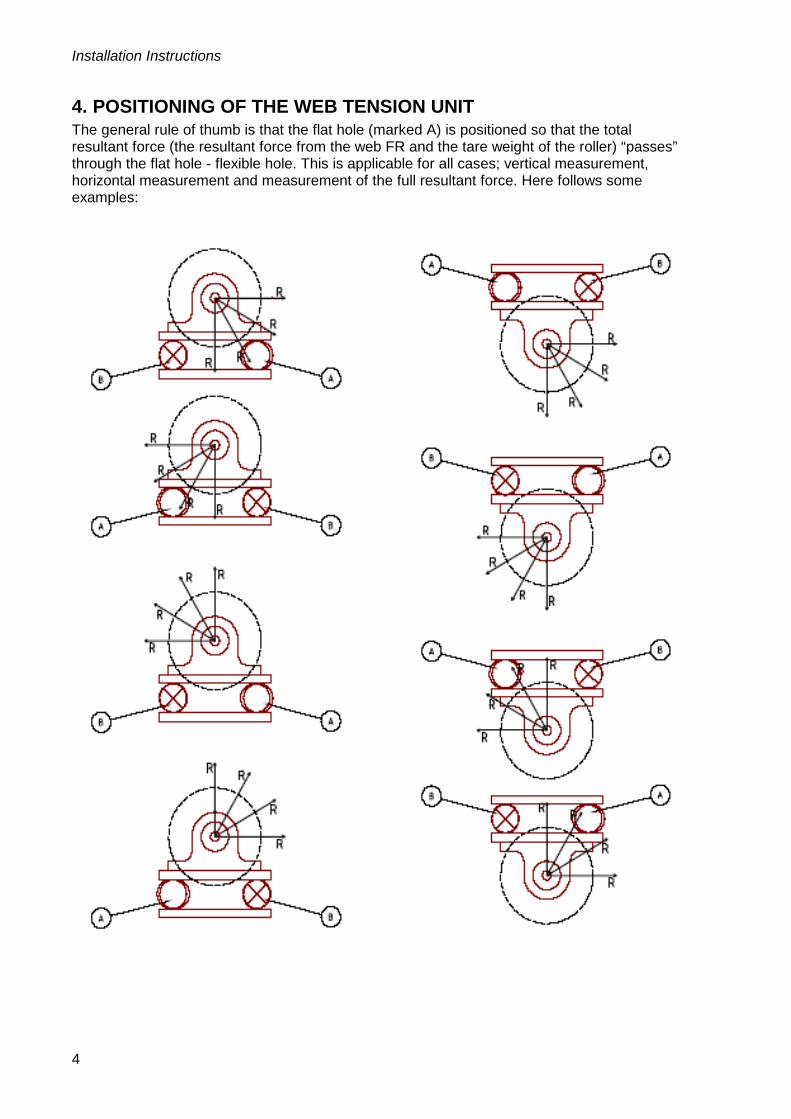
4. POSITIONING OF THE WEB TENSION UNIT The general rule of thumb is that the flat hole (marked A) is positioned so that the total resultant force (the resultant force from the web FR and the tare weight of the roller) “passes” through the flat hole - flexible hole. This is applicable for all cases; vertical measurement, horizontal measurement and measurement of the full resultant force. Here follows some examples:

Web Tension Units
5
5. INSTALLATION AND COMMISSIONING OF FMU-1 AND FMU-5
The FMU-1 and FMU-5 web tension unit works like a weighing scale, and certain number of rules should be respected during installation on site.
a) Install the web tension unit FMU-1 or FMU-5 on the mechanical support of the machine, and check with a spirit level, that the FMU-1 is perfectly horizontal (see drawing below), or vertical if wall mounted. Do the same operation on Operator/Tending Side and on Drive side.
b) Check that the KIS/KISD load cells are properly fixed on their block supports (surface
A on the KIS load cell should be on the same level as the surface B on the KIS mounting block. Thereafter check that the KIS/KISD load cells are properly orientated vertically, horizontally or in the direction of the resultant force FR, depending on the application. Normally this is already performed at delivery.
“FMU-1”

Installation Instructions
6
“FMU-5”
Depending on the application, the wrap angels and the nominal tension forces, the KIS/KISD load cells can be orientated either vertically, horizontally or in the direction of the resultant force FR. In order to have the KIS load cells properly orientated, check the arrow direction. For the KISD (FMU-5) use the two indicating holes as well.
In order to perform this load cell orientation, use a spirit level to check horizontality or verticality of the KIS/KISD. For directing the load cells in the direction of the resultant force, use a spirit level graduated arc.
c) Setting of the bearings / web tension unit parallelism on the measuring roll.
Web Tension Units
7
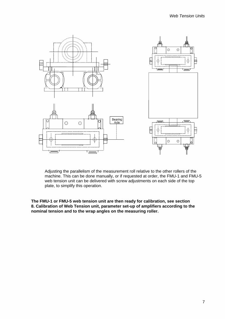
Adjusting the parallelism of the measurement roll relative to the other rollers of the machine. This can be done manually, or if requested at order, the FMU-1 and FMU-5 web tension unit can be delivered with screw adjustments on each side of the top plate, to simplify this operation.
The FMU-1 or FMU-5 web tension unit are then ready for calibration, see section 8. Calibration of Web Tension unit, parameter set-up of amplifiers according to the nominal tension and to the wrap angles on the measuring roller.
Installation Instructions
8
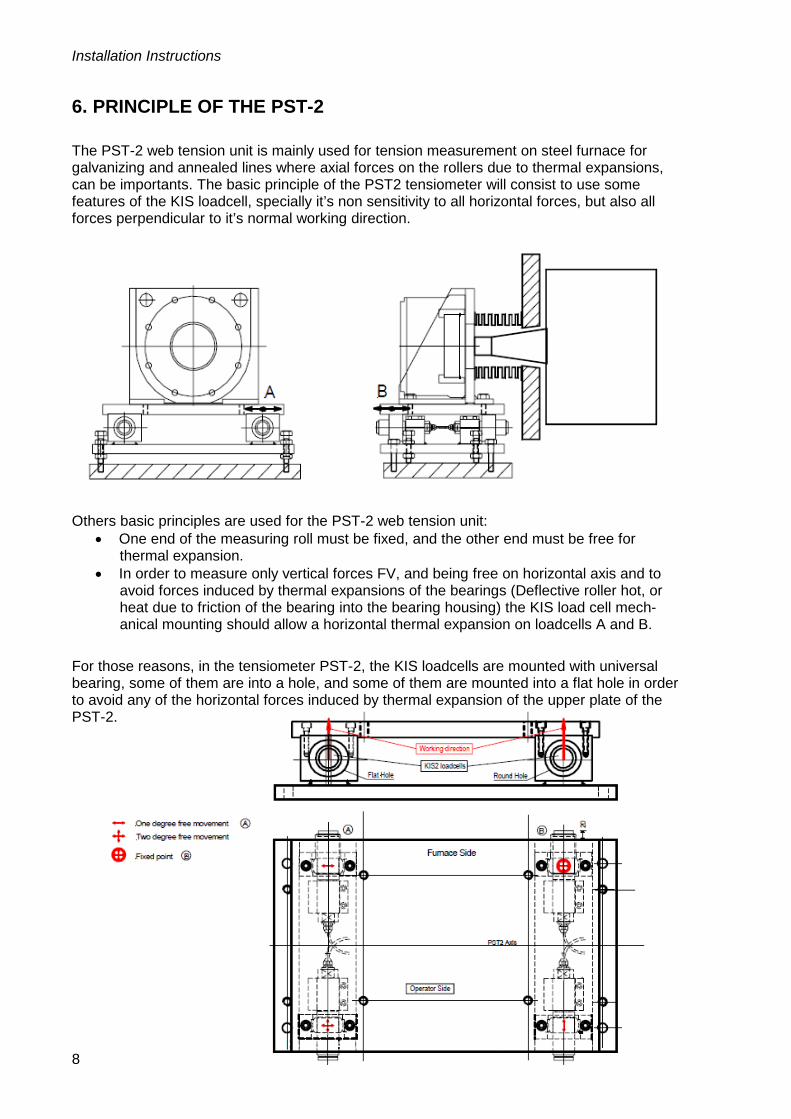
6. PRINCIPLE OF THE PST-2 The PST-2 web tension unit is mainly used for tension measurement on steel furnace for galvanizing and annealed lines where axial forces on the rollers due to thermal expansions, can be importants. The basic principle of the PST2 tensiometer will consist to use some features of the KIS loadcell, specially it’s non sensitivity to all horizontal forces, but also all forces perpendicular to it’s normal working direction.
Others basic principles are used for the PST-2 web tension unit:
• One end of the measuring roll must be fixed, and the other end must be free for thermal expansion.
• In order to measure only vertical forces FV, and being free on horizontal axis and to avoid forces induced by thermal expansions of the bearings (Deflective roller hot, or heat due to friction of the bearing into the bearing housing) the KIS load cell mech-anical mounting should allow a horizontal thermal expansion on loadcells A and B.
For those reasons, in the tensiometer PST-2, the KIS loadcells are mounted with universal bearing, some of them are into a hole, and some of them are mounted into a flat hole in order to avoid any of the horizontal forces induced by thermal expansion of the upper plate of the PST-2.
Web Tension Units
9
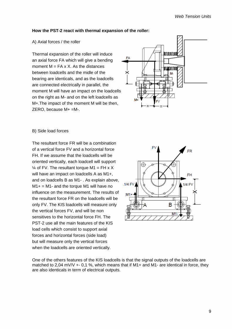
How the PST-2 react with thermal expansion of the roller: A) Axial forces / the roller Thermal expansion of the roller will induce an axial force FA which will give a bending moment M = FA x X. As the distances between loadcells and the midle of the bearing are identicals, and as the loadcells are connected electrically in parallel, the moment M will have an impact on the loadcells on the right as M- and on the left loadcells as M+.The impact of the moment M will be then, ZERO, because M+ =M-. B) Side load forces The resultant force FR will be a combination of a vertical force FV and a horizontal force FH. If we assume that the loadcells will be oriented vertically, each loadcell will support ¼ of FV. The resultant torque M1 = FH x X will have an impact on loadcells A as M1+, and on loadcells B as M1- . As explain above, M1+ = M1- and the torque M1 will have no influence on the measurement. The results of the resultant force FR on the loadcells will be only FV. The KIS loadcells will measure only the vertical forces FV, and will be non sensitives to the horizontal force FH. The PST-2 use all the main features of the KIS load cells which consist to support axial forces and horizontal forces (side load) but will measure only the vertical forces when the loadcells are oriented vertically. One of the others features of the KIS loadcells is that the signal outputs of the loadcells are matched to 2,04 mV/V +- 0,1 %, which means that if M1+ and M1- are identical in force, they are also identicals in term of electrical outputs.

Installation Instructions
10
7. INSTALLATION AND COMMISSIONING OF THE PST-2 The PST-2 web tension unit works like a weighing scale, and a certain number of rules should be respected during installation on site. a) Install the web tension unit PST-2 on the mechanical support of the machine, and check, with a spririt level, that the PST-2 is perfectly horizontal (see drawing below). Do the same operation on Operator/Tending Side and on Motor Side.
b) Check that the KIS load cells are properly fixed on their block supports (Surface A on the KIS load cell should be on the same level than surface B on the KIS mounting block), and properly oriented (Arrow / KIS load cell oriented vertically or horizontally, depending on the application). See drawing below.
Depending on the application, the wrap angles and the nominal tension forces, the KIS load cells can be oriented either vertically or horizontally.In order to have the KIS load cells properly oriented, check the arrow direction. In order to perform this load cells orientation, use a spririt level to check horizontality or verticality the working direction of the KIS loadcell.

Web Tension Units
11
c) Setting of the bearings / web tension unit parallelism on the measuring roll.
Use, eventually, the screws adjustments on each side of the PST2 tensiometers in order to adjust the parallelism of the measurement roll to the others rolls of the machine. The PST2 tensiometers are then ready for calibration, see section 8. Calibration of Web Tension Unit, parameter set-up of the amplifiers according to the nominal tension and to the wrap angles on the measuring roller.
Installation Instructions
12
8. CALIBRATION OF WEB TENSION UNIT
General When installing tensiometers either for web tension in a paper mill or strip tension in a galvanizing line or annealing line in steel industry, the same question rise up quite often: How can we be sure that the measure given by the tensiometers are the right ones? As matter of facts there is several ways to calibrate and check the tensiometers output values. When measuring with a instrument the output signal from the transducer (load cell), corresponding to the transducer load, is converted to a useful force or web tension information.
The conversion is controlled by several parameters, for more information see section Calibration for instrument to be used. Different instruments support different types of calibration methods.
• Theoretic calibration – Data sheet calibration – entry of calculated values based on values from transducer data sheet(s) and machine parameters (entry and exit angle or wrap angles).
• Known force calibration (Dead weight calibration) – storing of measured transducer signal for known forces.
Web Tension Units
13
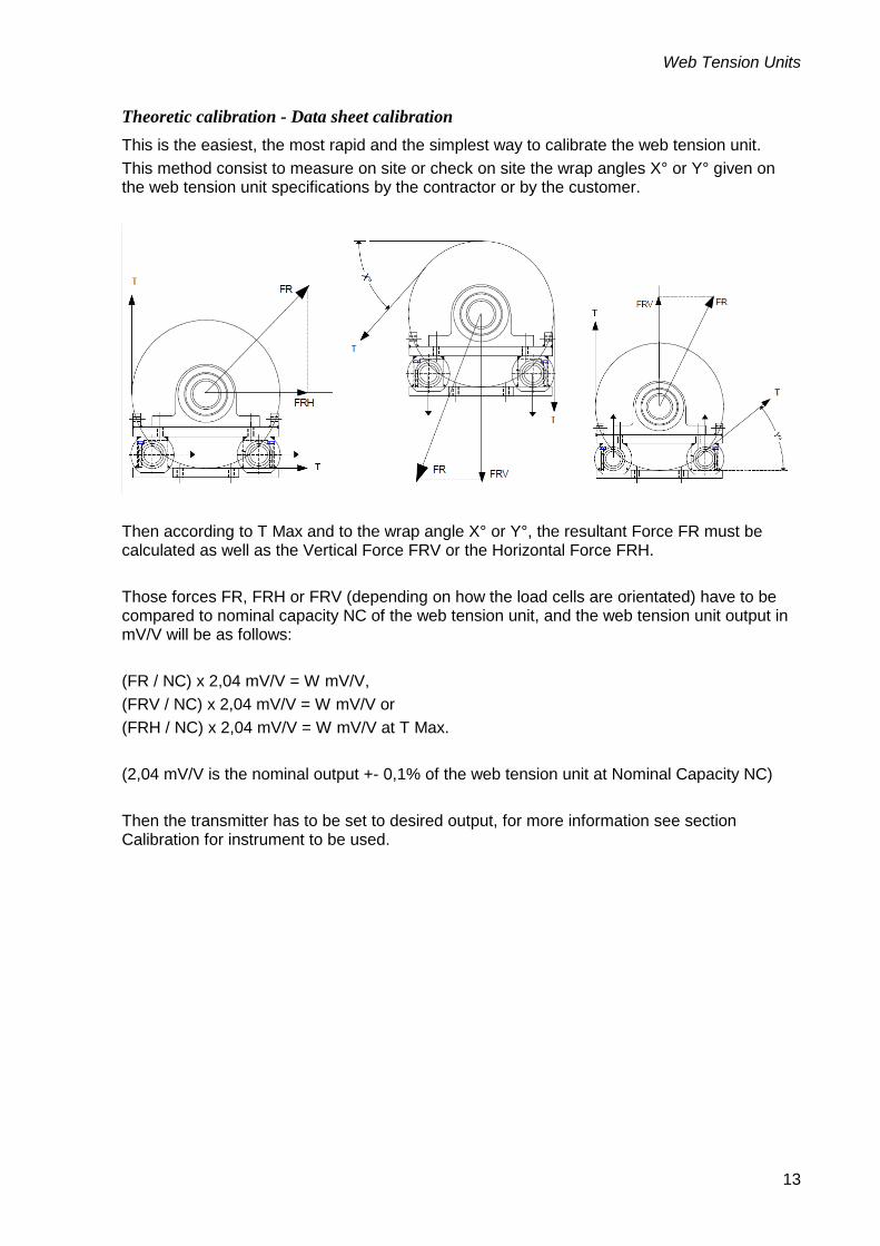
Theoretic calibration - Data sheet calibration This is the easiest, the most rapid and the simplest way to calibrate the web tension unit. This method consist to measure on site or check on site the wrap angles X° or Y° given on the web tension unit specifications by the contractor or by the customer.
Then according to T Max and to the wrap angle X° or Y°, the resultant Force FR must be calculated as well as the Vertical Force FRV or the Horizontal Force FRH. Those forces FR, FRH or FRV (depending on how the load cells are orientated) have to be compared to nominal capacity NC of the web tension unit, and the web tension unit output in mV/V will be as follows: (FR / NC) x 2,04 mV/V = W mV/V, (FRV / NC) x 2,04 mV/V = W mV/V or (FRH / NC) x 2,04 mV/V = W mV/V at T Max. (2,04 mV/V is the nominal output +- 0,1% of the web tension unit at Nominal Capacity NC) Then the transmitter has to be set to desired output, for more information see section Calibration for instrument to be used.

Installation Instructions
14
Known force calibration - Hydraulic jack calibration This method is only applicable for vertical or horizontal force measurement. In many cases, when the maintenance department have to check, on a regular basis the calibration of the web tension unit, one of the easiest way is to install on the machine, close to the tensiometers to be checked a mechanical arrangement in order to place a hydraulic jack with a manual pump, either with a digital pressure transducers (accuracy class expected about 0,5% of T Maxi) or a standard Load cell connected to a digital indicator (accuracy class expected about or better than 0,1% of T Maxi).
This method needs some investments at installation for the Hydraulic calibration system, but during maintenance calibration and checks do not need too much time at each calibration or check: About one hour per roller when everything goes all right.
Web Tension Units
15
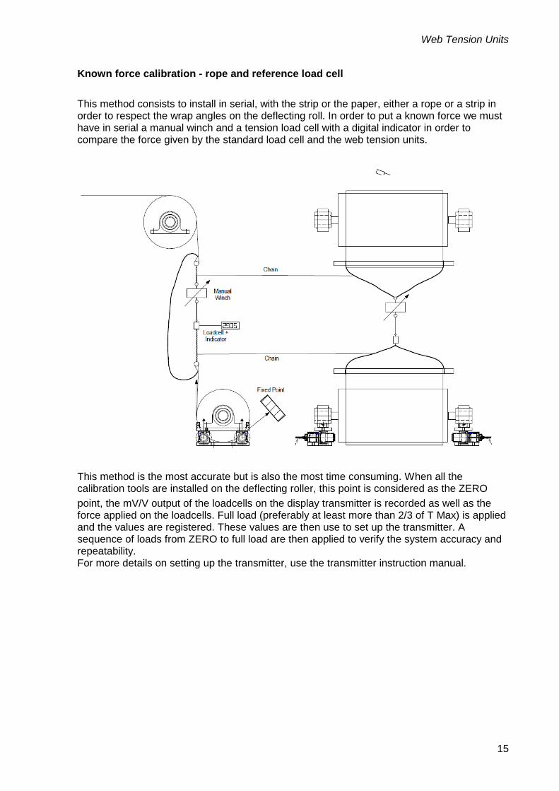
Known force calibration - rope and reference load cell This method consists to install in serial, with the strip or the paper, either a rope or a strip in order to respect the wrap angles on the deflecting roll. In order to put a known force we must have in serial a manual winch and a tension load cell with a digital indicator in order to compare the force given by the standard load cell and the web tension units.
This method is the most accurate but is also the most time consuming. When all the calibration tools are installed on the deflecting roller, this point is considered as the ZERO point, the mV/V output of the loadcells on the display transmitter is recorded as well as the force applied on the loadcells. Full load (preferably at least more than 2/3 of T Max) is applied and the values are registered. These values are then use to set up the transmitter. A sequence of loads from ZERO to full load are then applied to verify the system accuracy and repeatability. For more details on setting up the transmitter, use the transmitter instruction manual.

Installation Instructions
16
If the web angles are very small and the tension is very high (e.g. skin pass in steel strip) the forces in required in the rope would be to great. Instead the force should be applied with rope and reference load cell in the direction of the resultant force. If not possible, then data sheet calibration has to be used.


Vishay Nobel AB Vishay BLH Box 423, SE-691 27 Karlskoga, Sweden 3 Edgewater Drive, Norwood, MA 02726, USA Phone +46 586 63000 · Fax +46 586 63099 Phone: 781-298-2200 Fax: 781-762-3988 [email protected] [email protected] www.weighingsolutions.com www.weighingsolutions.com
Document no. 35221 Article no. 601 134 R0 © Vishay Nobel AB, 2012-10-04 Subject to changes without notice.