Embed Size (px)
Citation preview
1
Web and/ or Flange-Stiffened Lipped Channel Columns
Buckling Behaviour
H. Santana
Dissertation in Civil Engineering, Master Degree
Department of Civil Engineering, IST, Technical University of Lisbon
Abstract
This work present and discuss a group of results concerning the stability behavior of simply
supported-endend and fixed-ended cold-formed steel web and/or flange-stiffened lipped
channels columns. The members exibit V-shape in the web and/or flanges. The study identify a
significant number of geometries members, by dimensions of the cross section and length,
affected by interaction phenomena between local and distortional buckling modes. Through a
stability analysis we could identify columns geometries affected by local/distortional interaction
phenomena. All stability analyzes were performed with GBTUL1.0β software by using
Generalized Beam Theory (GBT). After indicating the essential characteristics and potential of
GBTUL1.0β program we presents the methodology adopted in the geometry columns selection,
with particular attention to the criteria considered in identifying the dimensions of the members.
Keywords: Cold-formed steel columns, Local and distortional buckling, Mode interaction, web and/or flange-stiffened
lipped channel columns,
1 Introduction
Most thin-walled cold-formed steel columns are susceptible to occurrence a interaction
phenomena between (i) local and (ii) distortional buckling. The local mode is
characterized by flexion of the internal walls without displacement of the longitudinal
edges while the distortional buckling mode is characterized by significant displacements
of the walls with one or more inner longitudinal edges. For the identification of the
interactions is necessary to perform an stability analysis. This analysis allows:(i) obtaining
curves relating the critical load parameter of structural elements to length and (ii)
identifying lengths values which allow to observe equal or very close bifurcation stress
associated to local and distortional buckling modes. The paper discusses two types of
support conditions (i) simply supported end section and (ii) fixed end section. The simply
supported condition is characterized by the following displacements/rotations are
prevented: (i) transversal translator displacements and torsional rotation (global), and (ii)

2
transversal membrane and flexural displacements (local). The fixed end section is
characterized by all the global and local displacements/rotations are prevented. This is
the condition implemented in the overwhelming majority of columns experimental tests,
obviously, the loaded end section axial translation must be free.
2 Stability of Columns
The web and flange-stiffened in the shape of "V" located at intermediate points of the walls in
the section will increase the resistance of local buckling. The web and flange-stiffened reduce
local thinness of the walls of the profile by wall segments subdivision increasing the critical
stress by simulating a “type” of elastic supports. It is necessary to take into account that (i) local
buckling mode is strongly influenced by the most slender element usually the web and (ii)
distortional buckling mode involves the rotation of the lips-flange around the connection flange –
web.
The Figure 2.1 shows the stability curves of channel sections with equal transverse dimensions
including width of web, flange, lips and thickness. The green line represents a stability curve of
a channel section which is observed the sturdy little capacity in which the flange act like a
cantilever. The red line represents the stability curve of a lipped-channel section and is
characterized by the occurrence of distortional buckling mode consequence of the lip. The blue
line represents the stability curve of web and flange-stiffened lipped channel section that
increase capacity in local buckling mode
Figure 2.1 – Stability curves of profiles with channel section.
Is defined as the longitudinal dimension value the length (L) of the bar. The transverse
dimensions are defined by (i) web (bw), (ii) flange (bf), (iii) lips (bs), iv) thickness (t), v) width of
strengthening the soul (S1w) vi) height of strengthening the soul (S2w), vii) strengthening the
flange width (S1f) and viii) strengthening the height of flange (S2f).
0
100
200
300
400
10 100 1000 10000
σb [
MP
a]
L [mm]

3
Figure 2.2 – Channel sections (a) web-stiffened, (b) flange-stiffened and (c) web and
flange-stiffened.
2.1 Examples
2.2.1 Columns simply supported
Through the stability analysis were determined curves. For examples of simply
supported appealed to the analytical solution with a half-wave (nw = 1). The minimum points of
each curve are respectively associated local and distortional buckling modes. The minimum
point of the curve contain information relating to (i) critical tensions ( ) and (ii) critical
length ( ) respectively associated local and distortional buckling modes.
The case studies may have different distortional critical stress below the local critical stress
ratio. The
relationship has the following range
in the situations with of local /
distortional interaction phenomena lie in the range
. To be able to compare with the
yield strength of the material the distorcional and local tensions are shown in MPa.
A Web-stiffened lipped channel columns
The initial geometric configuration called "A0" is as follows {(bw=190; bf=130; bs=13; t=1.2;
S1w=25; S2w=12.5) mm} which corresponds to the red curve stability the following graphs
of figures 2.3. By variation the width of the web in the "A0" section resulted in different
stability curves shown in Figure 2.3 with the following observations:
(i) The variation of the width of the web has the effect of changing the value of local a nd
distortional critical stress. The distortional buckling mode occured by rotation of the
flange-lip around the connection flange-web with the web act as spring relative to the
flange. By reducing the web width increases the stiffness of the spring and therefore
increases the value of the critical stress - when bw=190 mm passes to bw=140 mm the
σL=80 MPa increases to σL=82 MPa and σD=51 MPa increases to σD=57 MPa.
4
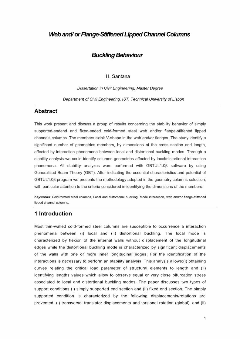
(ii) The σD/σL ratio increases with decreasing web width as it is observable in the table in
Figure 2.3 (where bw=190 mm passes to bw=140 mm and the σD/σL ratio increase from
64% to 70%).
(iii) The values of global tensions vary with the change of web width. This effect is due to
the fact that the instability of the long bars (L> 2200 mm) can be linked to the flexural-
torsional mode and flexural mode. The flexural mode is influenced by the higher inertia of
the section. The higher inertia of the section is more controlled by varying the web width
than the variation of the remaining transversal dimensions.
bf = 130 ; bs = 13; t = 1,2 ; S1w = 25 ; S2w = 12,5 [mm]
bw [mm]
140 190 240
LL [mm]
119 119 119
σL [MPa]
82 80 77
LD [mm]
927 1032 1150
σD [MPa]
57 51 45
σD/σL [%]
70% 64% 58%
Figure 2.3 – Stability curves σcr vs L (nw=1) of columns by variation the web width (bw).
After studying the various cases where only changed one transverse dimension, in order to
understand the importance in the change of σD/σL ratio, we arrive at a geometric configuration
that presents the local / distortional interaction phenomenon. This configuration is called "AB"
and has the following geometry {(bw=150; bf=140; bs=16; t=1; S1w=25; S2w=12.5) mm} which
corresponds to the orange curve stability in chart of Figure 2.4.
0
50
100
150
200
10 100 1000 10000
σcr
[M
Pa]
L [mm]

5
Figure 2.4 – Stability curves σcr vs L (nw=1) of columns on section “A0” and section “AB”.
2.2.2 Columns fixed
The stability analysis to determine the curves into fixed end columns using the
numerical solution. The analysis involves the numerical solution of the discretization length in
finite bar elements. The choice of the number of finite elements depends on the number of half-
waves used for obtaining the solution, making it less precise with the increase of the number of
half-waves.
Figures 2.5 show examples of geometry in fixed end sections with web/flange-stiffened lipped
channel columns. Distinguished cases interact with those who show a difference in the local
and distortional strain in the order of 0≤Δσ≤6 MPa. The Δσ is understood as the difference
between local and distortional critical stress in absolute value in MPa. In σD/σL ratio define the
cases where local / distortional interaction phenomena occurred when critical tensions are in
range of
.
B Web and flange-stiffened lipped channel columns
The observation of the table 2.1 and graph 2.5 enables the understanding of the changing
geometry of a web/flange-stiffened lipped channel columns, in order to reach a stability curve
presenting the local / distortional interaction phenomenon process. During the process were
made the following comments:
Specimen A0 AB
LL [mm] 119 119
σL [MPa] 80 49
LD [mm] 1032 1282
σD [MPa] 51 49
σD/σL [%] 64% 100%
0
50
100
150
200
10 100 1000 10000
σcr
[M
Pa]
L [mm]

6
(i) Initially, the process entails the conversion of the initial geometry "FV" to a final geometry
"FZ", passing through an intermediate geometry "FX". The transformation of "FV" to "FX" occurs
at the level of the flange width (bf=150 mm passes to bf=100 mm); thickness (t= 1.2mm
becomes t=1.4 mm). For changes "FX " to " FZ " are the web width (bw=210 mm shall bw=290
mm); the flange width (bf=150 mm shall bf = 100 mm); thickness (t=1.2 mm becomes t=1 mm);
the dimensions of web/flange-stiffen ( S1w=20 mm passes to S1w=30 mm ; S2w=10 mm passes to
S2w=15 mm; S1f=20 mm passes S1f=30 mm; S2f=10 mm passes S2f=15 mm).
(ii) The red stability curve "FV" presents local and distortional stress far apart. Observe the poor
linearity of the curve and presentation of a kind of "gap" between the values of the local and
distortional stress.
(iii) The green stability curve "FX" section gives local and distortional stress. It is apparent
discontinuity values between local and distortional stress very similar to the red curve stability.
(iv) The blue stability curve "FZ " section reflects the local/distortional interaction phenomenon.
It is possible to note the linearity of the curve stability and find a great number of local and
distortional tensions very similar There is a low local and distortional stress compared to the red
and green curves, and should this effect to the thick reduction.
Table 2.1 – Geometries of web and flange-stiffened lipped channel columns.
Specimen bw [mm] bf [mm] bs [mm] t [mm] S1w [mm] S2w [mm] S1f [mm] S2f [mm]
FV 210 150 20 1,2 20 10 20 10
FX 210 100 20 1,4 20 10 20 10
FZ 290 100 20 1 30 15 30 15

7
Specimen FV FX FZ
LL [mm] 670 832 1428
σL [MPa] 174 242 68
LD [mm] 10000 7230 10000
σD [MPa] 60 117 62
∆σ [Mpa] 114 126 6
σD/σL [%] 34 48 91
Figure 2.5 – Stability curve for the case of web and flange-stiffened lipped channel
columns and the respective table columns transverse dimensions.
3 Geometry Selection of columns
3.1 Criteria for geometry selection
The tax base in obtaining dimensions of criteria profiles, which are critical loads associated to
local, distortional and global buckling modes are:
i) 0,9≤ σD/σL ≤1
ii) 1≤ σD/σL ≤1,1
iii) σD ≈ σL << σG
In supported conditions:
i) simply supported end section
ii) fixed end section
0
100
200
300
10 100 1000 10000
σcr
[M
Pa]
L [mm]

8
By web/flange-stiffened lipped channel sections and it was suggested that the results respected
a set of geometric and physical criteria:
L [mm] bw [mm] bf [mm] bs [mm] t [mm] S1w [mm] S2w [mm] S1f [mm] S2f [mm] σD [MPa] σG [MPa]
> 300 > bf < bw > 0,1bf 1 ≤ t ≤ 2 20 10 20 10 ≤ 350 ≥ 3σD
(L/bw)>3,5 < 240 1≤(bw/bf)≤1,5 > S2w
25 12,5 25 12,5
> S2f
30 15 30 15
10 ≤ bs ≤ 20
Table 3.1 – Criteria for columns selection.
3.2 Results
A Simply supported columns (preview Table 3.2)
(i) The profile group of (C-28 to C-39) has the same thickness value (t=1 mm). The
determination process for this kind of geometry has particular difficulties in raising the
thickness value (t>1 mm). The progressive increase of the web and flange width led to
use the maximum lip width (bs=20 mm) and the progressive use web/flange-stiffen. Is
noticeable the progressive increase of the critical length induced by the progressive
increase of the transverse dimensions.
(ii) The range of lengths values L Є {530;860} mm . The transverse dimensions have
the following ranges of values bw {150;240}; bf {100;170}; bs {20} and t {1} in mm.
(iii) The values of the local maximum local/distortional stress varies in the range
Max{σL;σD} {97;253} and the global tensions in the range σG {3159;3734} in MPa.
(iv) Analyzing the results of the global average voltage is 24 times the maximum loc al
/distortional strain. The σD/σL voltage ratio in percentage is on average equal to 93
indicating a good quality of results.
B Fixed Columns (preview Table 3.3)
(i) The profile group of (F-67 to F-78) has the same thickness value (t = 1 mm). As in the
previous examples the progressive increase of the web and flange width led to use the
maximum lip width (bs=20 mm) and the progressive use web/flange-stiffen. Where the
progressive increase of the critical length is induced again by the progressive increase of the
transverse dimensions.

9
(ii) The profile group (F-79 to F-87) is characterized by the use of thicknesses (t =1.2,
t=1.4, t=1.6, t=1.8 mm). Using this range of thickness takes to apply the maximum dimension of
intermediate reinforcement (S1w=30; S2w=15; S1f=30; S2f=15 in mm).Thus it is possible to
achieve results with the occurrence of the local/distortional interaction phenomenon. Another
noticeable fact is significant reduction of the critical length in relation to increasing thickness.
(iii) The range of lengths values L {760,1680} mm . The transverse dimensions have the
following ranges of values: bw {150;240} ; bf {100;170} ; bs {20} and t {1;1.8} mm .
(iv) The values of the local maximum / distortional stress varies in the range Max{σL;σD}
{109,788} and the global tensions in the range σG {3241;25193} in MPa.
(v) Analyzing the results of the global average voltage is 26 times the maximum local /
distortional strain. The σD/σL voltage ratio in percentage is on average equal to 98 classifying the
quality of results as good.
3.2.1 Simply supported columns
3.2.1.1 Web and flange-stiffened lipped channel sections
Specimen L
[mm] bw
[mm] bf
[mm] bs
[mm] t
[mm] S1w
[mm] S2w
[mm] S1f
[mm] S2f
[mm] Max {σD;σL}
[MPa] σG
[MPa] σG/Max {σD;σL}
σD/σL [%]
C-28 530 150 100 20 1 20 10 20 10 253 3530 14 84
C-29 560 160 110 20 1 20 10 20 10 218 3582 16 83
C-30 600 170 120 20 1 25 12,5 25 12,5 202 3450 17 92
C-31 630 180 120 20 1 25 12,5 25 12,5 178 3417 19 95
C-32 670 190 130 20 1 25 12,5 25 12,5 157 3369 21 93
C-33 700 200 140 20 1 25 12,5 25 12,5 148 3734 25 93
C-34 740 210 150 20 1 25 12,5 25 12,5 132 3244 25 92
C-35 770 220 160 20 1 25 12,5 25 12,5 112 3422 30 89
C-36 760 210 150 20 1 30 15 30 15 132 3159 24 97
C-37 780 220 160 20 1 30 15 30 15 118 3294 28 99
C-38 820 230 160 20 1 30 15 30 15 107 3201 30 99
C-39 860 240 170 20 1 30 15 30 15 97 3177 33 97
Min 530 150 100 20 1 20 10 20 10 97 3159 14 83
Max 860 240 170 20 1 30 15 30 15 253 3734 33 99
Table 3.2 – Geometry of web and flange-stiffened lipped channel columns in simply
supported conditions
10
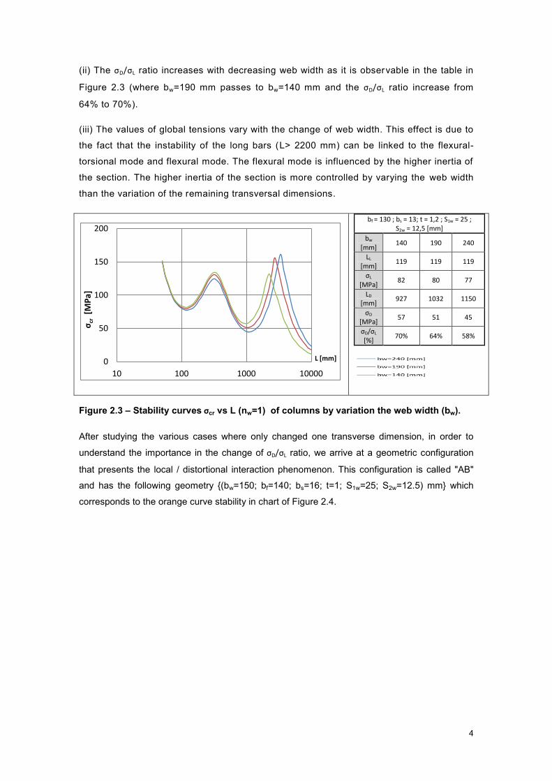
3.2.2 Fixed Columns
3.2.1.2 Web and flange-stiffened lipped channel sections
Specimen L
[mm] bw
[mm] bf
[mm] bs
[mm] t
[mm] S1w
[mm] S2w
[mm] S1f
[mm] S2f
[mm] Max {σD;σL}
[MPa] σG
[MPa] σG/Max {σD;σL}
σD/σL [%]
F-67 970 150 100 20 1 20 10 20 10 284 4216 15 96
F-68 990 160 110 20 1 20 10 20 10 244 4578 19 99
F-69 1140 170 120 20 1 25 12,5 25 12,5 226 3824 17 100
F-70 1260 180 120 20 1 25 12,5 25 12,5 199 3418 17 97
F-71 1280 190 130 20 1 25 12,5 25 12,5 176 3693 21 100
F-72 1330 200 140 20 1 25 12,5 25 12,5 157 3791 24 100
F-73 1380 210 150 20 1 25 12,5 25 12,5 140 3883 28 100
F-74 1430 220 160 20 1 25 12,5 25 12,5 126 3969 31 100
F-75 1200 210 150 20 1 30 15 30 15 145 4866 34 99
F-76 1560 220 160 20 1 30 15 30 15 132 3295 25 98
F-77 1630 230 160 20 1 30 15 30 15 120 3241 27 10
F-78 1680 240 170 20 1 30 15 30 15 109 3330 31 99
F-79 1280 220 160 20 1,2 30 15 30 15 187 4895 26 97
F-80 1370 230 160 20 1,2 30 15 30 15 171 4589 27 95
F-81 1150 230 160 20 1,4 30 15 30 15 227 6512 29 97
F-82 1020 240 170 20 1,4 30 15 30 15 661 22901 35 99
F-83 760 210 150 20 1,6 30 15 30 15 711 25193 35 98
F-84 980 220 160 20 1,6 30 15 30 15 657 17144 26 92
F-85 1000 230 160 20 1,6 30 15 30 15 591 17602 30 97
F-86 830 220 160 20 1,8 30 15 30 15 788 23473 30 99
F-87 910 230 160 20 1,8 30 15 30 15 697 20210 29 93
Min 760 150 100 20 1 20 10 20 10 109 3241 15 92
Max 1680 240 170 20 1,8 30 15 30 15 788 25193 35 100
Table 3.3 - Geometry of web and flange-stiffened lipped channel columns in fixed
conditions
4 Concluding Remarks
Through the stability analysis we could identify geometries of web/flange-stiffened lipped
channel columns affected by local/distortional interaction phenomena. The study of such
profiles developed to improve the methodology that allows to reach geometries sections
affected by local/distortional interaction phenomena in simply supported and fixed.
After an exhaustive study of the methodology described above were identified and selected a
set of columns with the occurrence local/distortional interaction phenomena in simply supported
and fixed. The selection of these profiles was based on the discovery of a set of geometric
criteria tensions and allowing its application in the commercial context.

11
The occurrence of the interaction phenomena results in reduced load capacity of the profiles.
The study of a methodology to understand how these phenomena occurred is very beneficial.
By analyzing the results of the selected profiles was possible to identify a number of conditions
for which the occurrence the local/distortional interaction phenomena is reduced. Indicate the
conditions identified below :
A. Simply supported columns
(i) In columns with web and flange-stiffened lipped channel sections the occurrence of
local/distortional interaction phenomena is reduced when they occurred simultaneously
the following conditions:
(i1) The thickness between 1.6 mm to 2.2 mm
(i2) For web/flange-stiffen the width less than 25 mm and height less than
12.5 mm.
(i3) The width lip less than 20 mm.
B. Fixed Columns
(ii) In columns with web and flange-stiffened lipped channel sections the occurrence of
local/distortional interaction phenomena is reduced when they occurred simultaneously
the following conditions:
(ii1) The thickness between 1,8 mm to 2,2 mm
(ii2) For web/flange-stiffen the width less than 25 mm and height less than
12.5 mm.
(ii3) The width lip less than 12 mm.
5 References
[1] Reis A.J., Camotim D., Estabilidade Estrutural, McGRAW HILL de Portugal. [2] Martins A.P., “Interacção entre Instabilidade Local-de-placa e Distorcional em Vigas de Aço Enformadas a Frio com Secção em C”, Tese de Mestrado em Engenharia de Estruturas,IST, Universidade Técnica de Lisboa, 2006. [3] Fena R., “Interacção entre Instabilidade Local e Distorcional em Colunas de Aço Enformadas a Frio de secção em "Hat", Tese de Mestrado em Engenharia Civil, IST, Universidade Técnica de Lisboa , 2011. [4] Prola L.C., "Estabilidade Local e Global de Elementos Estruturais de Aço Enformados a Frio".Tese de Doutoramento”, Departamento de Engenharia Civil, IST, Universidade Técnica de Lisboa, 2002.

12
[5] Silvestre N., “Teoria Generalizada de Vigas: Formulações, Implementação Numérica e Aplicações”. Tese de Doutoramento, Departamento de Engenharia Civil, IST, Universidade Técnica de Lisboa, 2005. [6] Dinis, P.B., Camotim, D. “Interacção local de-placa/distorcional em colunas de aço enformadas a frio: análise por elementos finitos em regime elástico e elasto-plástico”,Métodos Numéricos en Ingeniería (CMNI 2005 - Granada, 4-7/7), APARÍCIO, J.,FERRAN, A., MARTINS, J., GALLEGO,R., SÁ, J. (eds.), 145, 2005. (Artigo completo nas Actas em CD).
[7] Camotim D., Silvestre N., Dinis P.B.,.- “Análise numérica de elementos estruturais de aço
enformados a frio: desenvolvimentos recentes e perspectivas futuras”, Revista Sul-Americana de Engenharia Estrutural, , v. 3, n. 1, p. 55-100 (ASAEE),2006. [8] Dinis, P.B., Camotim, D., “Estabilidade de Perfis de Aço Enformados a Frio: Modelação por Elementos Finitos e Estudo da Influência das Condições de Apoio” VII Congresso de Mecânica Aplicada e Computacional, Universidade de Évora (14-16/4), 2003. [9] Camotim D., Dinis P.B. and Silvestre N., “Local/distortional mode interaction in lipped channel steel columns: post-buckling behaviour, strength and DSM design”, Proc. of 5th International Conference on Thin-Walled Structures (ICTWS 2008 Brisbane, 18-20/6), 99-114,2008. [10] Bebiano R., Pina P., Silvestre N., Camotim D, “GBTUL – A GBT-Based Code for Thin-Walled Member Analysis”, Proc. of 5th Conference on Thin-Walled Structures – Recent Innovations and Developments (ICTWS 2008 – Brisbane, 18-20/6), Vol. 2, 1173-1180, 2008. [11] Young B.K., Bong S.K.., Hancock G.J., “Compression tests of high strength cold-formed steel channels with buckling interaction”, Journal of Constructional Steel Research n. 65 p. 278-289, 2009. [12] Yang, D., Hancock, G.J., “Compression tests of high strength steel channel columns with interaction between local and distortional buckling”, Journal of Structural Engineering (ASCE), v. 130, n. 12), p. 1954-1963, 2004a. [13] Yang, D., Hancock, G.J., “Experimental Study of High-Strength Cold-Formed Stiffened-Web C-Sections in Compression”, Journal of Structural Engineering (ASCE),p. 162-172, 2011. [14] Bebiano R., Silvestre N., Camotim D., “GBTUL 1.0β – “Buckling and Vibration Analysis of Thin-Walled Members - GBT Theoretical background",Department of Civil Engineering and Architecture, DECivil/IST, Technical University of Lisbon,Portugal,2008. [15] Bebiano R., Silvestre N., Camotim D., “GBTUL 1.0β - Buckling and Vibration Analysis of Thin-Walled Members - Program manual",Department of Civil Engineering and Architecture, DECivil/IST,Technical University of Lisbon,Portugal,2008