Embed Size (px)
Citation preview

Waterford City Flood Alleviation Scheme | Paper first presented to Engineers Ireland on 12.02.2014 | PAGE 1
Waterford City Flood Alleviation SchemeGavin O’Donovan, BE CEng MIEI, Associate, RPS Consulting Engineers Ltd(Paper first presented to Engineers Ireland on 12th Feb 2014)

PAGE 2 | Gavin O’Donovan, BE CEng MIEI, Associate, RPS Consulting Engineers Ltd
� Fig 1.1: Glass Floodwalls on Adelphi Quay

Waterford City Flood Alleviation Scheme | Paper first presented to Engineers Ireland on 12.02.2014 | PAGE 3
1.0 SYNOPSIS
This paper outlines the background and implementation of the Waterford City Flood Alleviation Scheme from the initial preliminary reports in the late 1990s to its projected construction completion in 2014.The scheme consists of the containment of the John’s River and the River Suir within their respective channels through the urban area of Waterford City. This is achieved through the construction of flood defences, in the form of reinforced concrete walls, glass walls, sheetpiled walls, embankments, stormwater pumps etc.
The works were constructed in three separate civil works contracts and on completion will protect the city from flooding from the rivers for events up to the 0.5% annual exceedance probability (1 in 200 year) in tidal areas and up to the 1% annual exceedance probability (1 in 100 year)) in non tidal areas.

PAGE 4 | Gavin O’Donovan, BE CEng MIEI, Associate, RPS Consulting Engineers Ltd
2.0 INTRODUCTION
Waterford City is arguably the oldest city in Ireland dating back to the late 9th century and the time of the Vikings. The name ‘Waterford’ is derived from the old Norse word ‘Vedrarfjiordr’. The Vikings realising the Strategic and trading importance of the rivers which empty into Waterford Harbour built a longphort or dock at the confluence of the St John’s River and the River Suir.
� Fig 2.1: Waterford City Location Plan
The geography of the city is dominated by the River Suir. The city is mostly located on the south bank of the river over 20km upstream from the sea at Dunmore East.
� Fig 2.2: River Suir and Waterford City South Quays
The smaller John’s River (catchment area of approx 50km2) rising in the hills near Tramore flows in a generally northeasterly direction through the city before joining the River Suir at Scotch Quay. While the River Suir’s tidal reach extends well beyond the city, the John’s River is tidal only over its last approximately 3kms.
� Fig 2.3: Waterford City Extents
Serious flooding was regularly experienced in the city due to high water levels in the River Suir and the John’s River. This flooding was most frequent in the flowing areas:
» The South Quays
» Scotch Quay
» Canada St/ Newtown Rd/ Park Rd
» Waterside
» Poleberry
» Tramore Rd
Following preliminary studies in the late 1990s, the Office of Public Works (OPW) commissioned the preparation of a preliminary report to devise a scheme to alleviate flooding in the city from the rivers. This paper details the background and implementation of that scheme.

Waterford City Flood Alleviation Scheme | Paper first presented to Engineers Ireland on 12.02.2014 | PAGE 5
3.0 HISTORICAL FLOODING
Historically, Waterford City has suffered badly from flooding over the years. A review of records and press archives revealed that some areas of the city were affected by flooding in Oct 1886, Nov 1916, Dec 1925, Jan 1926, Aug 1946, Oct 1949, Dec 1960. More serious flooding was recorded in:
» October 1961 ‘…..water entered many shops and caused damage in many case. Low-lying areas throughout the town were under water and a num-ber of houses were flooded…’
� Fig. 3.1 Munster Express October 1961
» December 1979 ‘….waters up to two feet deep covered cross-city routes …’
» December 1981 ‘….River Suir overflowed onto the quays...Worst affected areas were Park Road and Canada Street where the floods rose to a height of over three feet..’
» August 1986 ‘….The worst hit city areas were Pole-berry, Bath Street, Johnstown, Park Road and The Quay…’
� Fig. 3.2 Waterford News & Star September 1986
» February 1990 ‘…shopkeepers and hoteliers on Waterford quay front barricaded their premises with sandbags…’
» January 1996 ‘…floodwaters on the quay as high
tides once again caused disruption..’
� Fig.3.3 Munster Express January 1996
» November 1997 ‘… Flooding on the Quays and Park Road in Waterford caused severe traffic disrup-tions…’
» December 1999 ‘…Gardai closed off the quays in Waterford when the River Suir overflowed its banks and made the main thoroughfare through the city impassable..’
» February 2002 ‘…In Waterford City the Suir burst its banks along the quays… while there was also flooding in the Waterside and Scotch Quay areas …’
In more recent times extreme events were experienced in October 2004, November 2009, January 2014 and February 2014.
The areas typically most affected can be seen in the layout plan below.

PAGE 6 | Gavin O’Donovan, BE CEng MIEI, Associate, RPS Consulting Engineers Ltd
� Fig. 3.4 Areas typically affected by floods
1) South Quays
The South Quays were subject to regular inundation with the River Suir overtopping the quays during an extreme tidal event, flooding the main thoroughfare through city and the adjoining shops and businesses.
� Fig. 3.5 Flooding on Quays in February 1989
� Fig. 3.6 Regular sight on Quays (Feb 1994)
2) Scotch Quay
Similarly, during extreme tidal events the John’s River overtopped its banks at Scotch Quay flooding the surrounding lowlying areas.
� Fig 3.7 River overtopping at Scotch Quay (Mar 2008)
3) Canada St/ Newtown & Park Rds
These lowlying areas are regularly under water from tidal waters from both the John’s River and the River Suir.
� Fig 3.8 Canada Street (Oct 2012)

Waterford City Flood Alleviation Scheme | Paper first presented to Engineers Ireland on 12.02.2014 | PAGE 7
� Fig 3.9 Newtown Road (Jan 2014)
4) Waterside
Lowlying mostly residential properties were subjected to regular flooding from the tidal section of the John’s River.
5) Poleberry
The lowlying area including Bath St and the adjoining residential properties are subject to flooding from the John’s River which can be tidal and/or fluvial in nature in this area.
� Fig 3.10 Post Flood Clean Up in Poleberry (Feb 2014)
6) Tramore Rd/ Inner Ring Rd Roundabout
Lowlying roads and adjoining commercial premises are subject to flooding when high water levels in the John’sRiver and its tributary (Lisduggan Stream) back up the stormwater drainage system. Again, flooding in this area can be either tidal or fluvial or a combination of both.
� Fig 3.11 Tramore Road (Nov 2009)
7) Tramore Road
The lowlying Tramore Road between the Inner and Outer Ring Roads runs parallel to the John’s River and adjacent to the Kilbarry Bog. Following prolonged and heavy rainfall events the bog becomes saturated and the John’sRiver bursts its banks flooding the Tramore Road. This section of road becomes impassable and may be closed several times a year.
� Fig 3.13 Tramore Road (Nov 2009)

PAGE 8 | Gavin O’Donovan, BE CEng MIEI, Associate, RPS Consulting Engineers Ltd
4.0 EVOLUTION OF SCHEME
4.1 Main Drainage Works
In the mid 1990s Waterford Corporation (City Council) completed the first Phase of the Main Drainage Scheme which improved drainage in the city. The scheme included the construction of a number of large interceptor sewers parallel to the rivers to facilitate the removal of most outlets discharging directly to the rivers. The interceptor sewers drain to the Waterpark Pumping Station where sewage is pumped on to the Treatment Plant at Belview and stomwater overflows (pumped) directly to River Suir.
The system has all but eliminated flooding from surcharging sewers and waters backing up the system and has facilitated the quick drainage of areas inundated by floodwaters. However, it is not capable of dealing with the large volumes of floodwater associated with the rivers overtopping their banks.
In the late 1990s Waterford Corporation and their main drainage consultants prepared a number of minor reports on the outstanding flooding issues in the city. However, the scale of the problem necessitated a more comprehensive study.
4.2 John’s River (Waterford City) Main Drainage Scheme
In 2000 the Office of Public Works (OPW) commissioned engineering consultants M.C. O’Sullivan & Co. (MCOS) to devise an integrated scheme which would alleviate flooding in the John’s River catchment within the urban boundary.
Options Considered
The potential methods of flood alleviation examined were:
» Flood Defence Walls and Embankments
» Channel Improvement
» Tidal Control structure
» Combination of the above options
Hydraulic Model
In order to assess the extent and merits of each option it was necessary to construct a hydraulic model of the John’s River system within the study area. The creation and calibration of the hydraulic model (ISIS software package) was carried out by HR Wallingford.
» The water profile in the study area was determined by two factors, the tide level in the Suir and the flow in the John’s River. Downstream of Hardy’s Bridge (See Fig. 4.1), the design flood profile is dependent on the tide alone. At the Tramore Road, upstream of the Inner Relief Road Roundabout, the design flood profile is governed by the flow in the river only. In the 2km interactive reach between these two points the flood levels are affected by the relative timing of the peak tides and flows.
Recommendations
The report recommended that containment of flood flows within the river channels was to be implemented as the preferred solution. This was to be achieved through the construction of reinforced concrete flood walls and flood embankments from Grattan Quay to Waterpark on the River Suir south bank and on both banks of the John’s River and its tributary (Lisduggan Stream) from its confluence with the River Suir to the Tramore Road area. The Tramore Road was to be raised by approximately 1.5m.
Design Criteria
The flood defences were to be a maximum of 1.1 - 1.2m above ground levels to preserve river views. A factor of safety over the calculated flood level was required to allow for uncertainty in flow estimation, global warming, loss of channel efficiency etc. The report recommended that freeboard values of 0.5m and 0.3m be used in tidal and non-tidal areas respectively. The flood defence works were to provide protect against flood events up to a 100year return period. The raising of the Tramore Road was to provide protection against flood events up to the 20 year return period, including a 0.3m freeboard allowance.

Waterford City Flood Alleviation Scheme | Paper first presented to Engineers Ireland on 12.02.2014 | PAGE 9
Cost Benefit
A cost benefit analysis was completed at the time of the Preliminary Report. The recommended option had, at the time, an estimated all-in cost of IR£22.7M with a corresponding benefit to cost ratio of 1.5.
� Fig.4.1 Layout Plan of Benefitting Areas
Public Exhibition
The scheme was advanced to Public Exhibition Stage where the proposals were put on public display for a number of weeks in early 2002. An Environmental Impact Statement was also prepared for the scheme at this time. However, the scheme was never formally certified by the OPW Minister.
4.3 Potential for Phasing the Works
In 2003 the OPW commissioned RPS-MCOS to access at a preliminary level the potential viability of phased works for the John’s River scheme. The study recommended the following four phases:
» Phase 1: Work on the River Suir (South Quays) upstream of its confluence with the John’s River and on the John’s River northern bank to Hardy’s Bridge.
» Phase 2: Work on the River Suir (south bank) downstream of its confluence with the John’s River and on the John’s River southern bank to the Link Road Bridge.
» Phase 3: Work on the north bank of the John’s River from Hardy’s Bridge to upstream of Wyse’s Bridge.
» Phase 4: Work on the Lisduggaan Stream and on the John’s River from upstream of Wyse’s Bridge to upstream of the Tramore Rd/ Inner Ring Road Roundabout.
� Fig.4.2 Layout Plan of Proposed Phases & Benefitting Areas
Each phase was to be capable of ‘standing alone’ and providing adequate protection to the areas directly behind the flood defences and have a positive benefit to cost ratio. The proposed raising of approximately 3km of the Tramore Road and associated river channel works was considered as a fifth phase but was omitted because the calculated cost benefit ratio (0.05) deemed the phase to not be economically viable.*
*Note that a section of the Tramore Road was upgraded in a Contract in 2010. The section of road was raised above the predicted 1 in 2 year flood level.

PAGE 10 | Gavin O’Donovan, BE CEng MIEI, Associate, RPS Consulting Engineers Ltd
4.4 Glass Floodwalls
In 2006 plans were being made to advance the first phase (South Quays) of the flood alleviation scheme.
Concept
However, there were concerns locally that the proposed flood walls along the South Quays would cut off views of the River Suir altering the city inhabitants long historical connectivity with the river. Waterford City Council (WCC) members were anxious to maintain the cities relationship with what was historically described as the ‘noblest quay in Europe’* Therefore, the concept of a transparent flood defence system was presented to the elected members in 2007 as part of the Part 8 Planning process for the Phase 1 contract.
*Architectural Historian Mark Girouard
Background Research
As designers, RPS consulted with private glass manufacturing companies such as OMC Engineering and Carey Glass on potential designs for a system appropriate to Waterford City. RPS researched other projects where glass was used as a structural material. In particular, RPS investigated the use of glass for flood defence purposes in projects throughout the world. A number of German companies and one UK company were developing a glass panel flood defence product. In 2008, a delegation from RPS, OPW and WCC travelled to Germany to visit two sites near Hamburg where sections of glass flood wall had been incorporated into recently completed schemes.
� Fig.4.3 Glass flood defences in Neufeld, River Elbe (Germany)
� Fig.4.4 Glass flood defences in Brake (Germany)
Design Criteria
A 1.1m high by 3.0 long glass panel was chosen as the optimum design. The glass would have to retain the full height hydrostatic load of 14KN/m2 including a wind and crowd load of 1.5KN/m2. The glass should be capable of withstanding a point impact load of up to 1.5KN. A risk assessment concluded that this load was sufficient without having to reduce the support spacing.
OMC Engineering and Carey Glass fabricated a 6m long sample panel which was transported to Waterford and unloaded for display on Adelphi Quay to allow the OPW and WCC personnel to view and comment.
� Fig.4.5 The 6m long sample panel at Adelphi Quay
Detailed Design
The finished design called for a 39.5mm thick glass consisting of two heat soaked toughened 19mm thick panels with a 1.5mm thick pvb layer. Structural Steel supports, base plates and U channels, silicone seals and timber handrail were all specified in detail

Waterford City Flood Alleviation Scheme | Paper first presented to Engineers Ireland on 12.02.2014 | PAGE 11
� Fig.4.6 Detailed Design Drawing of Glass Floodwall
The glass floodwall system was to be constructed on the quay edge* directly replacing the existing metal guardrail. In all areas the existing concrete plinths were raised to accommodate the system. The level of the plinth under the proposed glas wall was to be set at a minimum of 2.9mOD Malin Hd.
* A structural condition assessment of the existing quays had been previously carried out in 2006. The assessment concluded that the flood defences could be constructed on the existing concrete plinths along the quays without comprising the integrity of the existing structures.
4.5 Review of Design Water Levels
In 2008, a review of the proposed design water levels was carried out to account for the updated OPW policy of providing protection in tidal areas of up to 200 year return period events (0.5% Annual Exceedance Probability) and to incorporate the records from a water level gauge installed by the OPW at Adelphi Quay at the outset of the scheme in 1999.
Annual maximum water levels in Waterford city were available for over 30 years from a number of sources - old reports, gauge at ESB Station in Great Island, Waterford Harbour and the new OPW gauge at Adelphi Quay. The annual maxima method was used to determine the annual exceedance probability and corresponding return periods. The Generalised Extreme Value (GEV) family of curves (straight line for Gumbel Distribution) was applied to data and the line was extrapolated to determine the larger return periods. The results of this analysis led to new 100 year and 200 year return period water levels in the River Suir of 3.1mOD and 3.2mOD respectively. This represents an increase of over 0.2m on previously predicted water levels.
River Sec-tion
100yr RP Water Level
200yr RP Water Level
Min Flood Defence Level
Quays - River Suir 3.2mOD 3.7mOD
Tramore Rd - John’s River 3.9mOD 4.2mOD
Table 4.1 Updated Design Flood Levels

PAGE 12 | Gavin O’Donovan, BE CEng MIEI, Associate, RPS Consulting Engineers Ltd
5.0 PHASE 1 CIVIL WORKS CONTRACT
5.1 Description
The Phase 1 Contract consists of the construction of flood defences along the south quays of the River Suir from Rice’s Bridge to Adelphi Quay and on the north bank of the John’s River from its confluence with the River Suir to the Courthouse Grounds.
� Fig. 5.1 Layout Plan of Phase 1 with Benefitting Areas
The OPW signed a Section 85 agreement in accordance with the Local Government Act 2001 with Waterford City Council to allow the council to act as agents for the OPW to carry out the works.
Topographical and structural surveys and geotechnical site investigations were completed as part of the detailed design. The Contract was tendered in June 2008 using the Department of Finance Public Works Conditions of Contract. This was one of the first projects in the country to use the new contracts, certainly the first for Waterford City Council.
19 number Tenders were received before the deadline in August 2008. Tenders ranged from €2.0M to €3.8M (excl VAT). A local contractor, Niall Barry & Co. Ltd, had the most economically advantageous tender and was awarded the contract in December 2008. He commenced on site in February 2009 and took approximately 20 months to reach substantial completion (Oct 2010).
5.2 Construction Stage
The Contract included the construction of 921lin.m of glass floodwall, approximately 76 lin.m of granite clad reinforced concrete floodwall, 32lin.m of cut limestone clad reinforced concrete floodwall, 110lin.m of painted reinforced concrete floodwall and 10no. floodgates along the River Suir Quays; and paving and landscaping works to areas behind the defences.
The general sequence of work involved the removal of the existing quay edge guardrail; excavation for foundations where necessary;
� Fig 5.2 Excavation for foundations along Adelphi Quay
construction of reinforced concrete foundations and plinths,
� Fig 5.3 Steel Fixing for foundations along Adelphi QuayFig
� 5.4 Concrete pour for plinth along Adelphi Quay

Waterford City Flood Alleviation Scheme | Paper first presented to Engineers Ireland on 12.02.2014 | PAGE 13
erection of structural steel supports; installation of glass panels; and the fixing of the cut stone cladding
� Fig 5.5 Installation of First Section of Glass along Adelphi Quay
� Fig 5.6 Finished Glass Floodwall along Adelphi Quay
� Fig 5.7 Removal of existing guardrail along Merchant’s Quay
� Fig 5.8 Reinforcement for concrete plinth along Merchant’s Quay
� Fig 5.9 Coring into new concrete plinth for structural steel base plate along Merchant’s Quay
� Fig 5.10 Erection of Structural Steel Supports along Merchant’s Quay

PAGE 14 | Gavin O’Donovan, BE CEng MIEI, Associate, RPS Consulting Engineers Ltd
� Fig 5.11 Finished Glass Floodwall along Merchant’s Quay
Other works included the construction of almost 200 lin.m of masonry faced reinforced concrete floodwall on the John’s River at Bolton Street carpark;
� Fig 5.12 Reinforced concrete floodwall foundations in Bolton St Carpark
� Fig 5.13 Masonry finish to Bolton St Carpark Floodwall
and 205lin. of flood embankment on the John’s Riv-er through the Courthouse Grounds.
� Fig 5.14 Construction of Flood Embankment and new path in Courthouse Grounds
The Contract also included the installation of over 100 no. non return valves on existing storm water outlets of sizes varying from 100mm dia to 900mm dia;
� Fig 5.15 Installation of Non Return Valves on existing stormwater outlets along the John’s River
and remedial works to existing river walls.
� Fig 5.14 Gunite spray to existing river wall on the John’s River

Waterford City Flood Alleviation Scheme | Paper first presented to Engineers Ireland on 12.02.2014 | PAGE 15
Archaeology
Excavations for the wall foundations along Adelphi Quay led to the discovery of archaeological artefacts in the form of large mooring chains and anchor logs buried in the quay that dated back to 18th century.
� Fig 5.15 Archaeologist on Adelphi Quay
Grattan Quay
The section of quays north of Rice’s Bridge, ‘Grattan Quay’ was included in the original scheme. Waterford City Council had planned to upgrade the road along this quay which would have incorporated the necessary flood defences. However, with the economic downturn the road project was unlikely to proceed in the foreseeable future.
A separate cost benefit analysis of flood defences for the Grattan Quay calculated a very positive benefit cost ratio of 37. It was agreed to include flood defence works to protect the area in the Phase 1 contract. The works included the construction of approximately 200lin.m of reinforced concrete floodwall, drainage, and new footpath and carparking spaces for a cost of approximately €0.4 M.
� Fig 5.16 Foundations for Reinforced Concrete Floodwall at Grattan Quay
� Fig 5.17 Completed Flood Defences at Grattan Quay
Challenges
There were a number of challenges encountered during the works which can be summarised as follows:
Restricted Working Space and Services
The works site in many areas was limited to a nar-row strip between the existing quays and trafficked areas. This led to very restricted working space for excavations and associated difficulties dealing with existing services.
PAGE 16 | Gavin O’Donovan, BE CEng MIEI, Associate, RPS Consulting Engineers Ltd
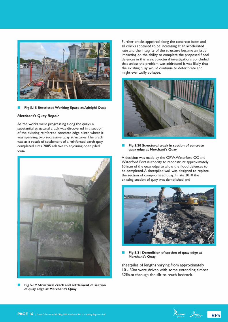
� Fig 5.18 Restricted Working Space at Adelphi Quay
Merchant’s Quay Repair
As the works were progressing along the quays, a substantial structural crack was discovered in a section of the existing reinforced concrete edge plinth where it was spanning two successive quay structures. The crack was as a result of settlement of a reinforced earth quay completed circa 2005 relative to adjoining open piled quay.
� Fig 5.19 Structural crack and settlement of section of quay edge at Merchant’s Quay
Further cracks appeared along the concrete beam and all cracks appeared to be increasing at an accelerated rate and the integrity of the structure became an issue impacting on the ability to complete the proposed flood defences in this area. Structural investigations concluded that unless the problem was addressed it was likely that the existing quay would continue to deteriorate and might eventually collapse.
� Fig 5.20 Structural crack in section of concrete quay edge at Merchant’s Quay
A decision was made by the OPW, Waterford CC and Waterford Port Authority to reconstruct approximately 60lin.m of the quay edge to allow the flood defences to be completed. A sheetpiled wall was designed to replace the section of compromised quay. In late 2010 the existing section of quay was demolished and
� Fig 5.21 Demolition of section of quay edge at Merchant’s Quay
sheetpiles of lengths varying from approximately 10 - 30m were driven with some extending almost 32lin.m through the silt to reach bedrock.

Waterford City Flood Alleviation Scheme | Paper first presented to Engineers Ireland on 12.02.2014 | PAGE 17
� Fig 5.22 Installation of sheetpiled wall along quay edge at Merchant’s Quay
On completion of the sheetpiling a reinforced concrete capping beam was constructed on top of the sheetplied wall and the glass flood defence were completed as per the original contract.
� Fig 5.23 Glass floodwall construction on newly constructed section of Merchant’s Quay
The repair works delayed completion by a number of months and cost an additional approximately €0.5M.
Custom House Quay
As mentioned above, the quays along the River Suir in Phase 1 consists of several different types of structure. In the open piled structures the watertightness of the concrete deck was critical.
� Fig 5.24 View from River of underside of Open Piled Quays
The lateral joints between successive quay structures were exposed, saw cut and sealed with bitumen and a mass concrete plug before reinstating the surface.
� Fig 5.25 Exposing Lateral Joints from above in Custom House Quay
� Fig 5.26 Bitumen Seal of exposed joints prior to concrete plug work
However, Custom House Quay proved difficult to make fully watertight. The quay compromises several

PAGE 18 | Gavin O’Donovan, BE CEng MIEI, Associate, RPS Consulting Engineers Ltd
different types of structure of varying condition – some sections being of recent re-construction (due to a partial collapse), some sections in a poor structural state and other sections with evidence of remedial works having been carried out.
� Fig 5.27 View beneath structure showing differing constructions
Closer inspection of the underside of the quay led to a question mark over its structural integrity. Access difficulties led to the requirement for a specialist underwater structural survey. At the time of writing (Feb 2014), this survey was been organised and until its completion and its recommendations implemented some seepage through the structure in extreme tides will remain an issue.
� Fig 5.28 River water bubbling up through the carpark surface at Custom House Quay
5.3 Finishes
From the early stages of the project the importance of providing a finish that would enhance the quays was a high priority. The Contractor, Niall Barry, being a native of Waterford City, was fully committed to the project and his input and workmanship was instrumental to the overall success of the project.
� Fig 5.29 Limestone finish on riverside of flood defences near Rice’ Bridge.
Waterford City Council and the entire project team invested considerable effort into ensuring a high quality finish appropriate to the city and its renowned quays. A number of finishes were designed suitable to different areas. A cut limestone finish to walls and plinth under glass was chosen for Adelphi Quay.
� Fig 5.30 Cut Limestone to concrete plinth and relayed existing flagstone paving
A cut granite stone finish was specified for Merchant’s Quay.

Waterford City Flood Alleviation Scheme | Paper first presented to Engineers Ireland on 12.02.2014 | PAGE 19
� Fig 5.31 Cut Granite stone to concrete walls and plinth along Merchant’s Quay
A sandstone masonry finish was constructed on the concrete floodwall on the John’s River.
� Fig 5.32 Masonry facing of Floodwall in Bolton St Carpark
There was also the opportunity of enhancing the character of areas behind the flood defences and providing new areas for the public to engage with the rivers again. For example, at a focal point on Adelphi Quay outside the Tower Hotel, Waterford City Council had text and images printed in a number of the glass panels.
� Fig 5.33 Finish around Monument at Adelphi Quay
The text was from historical writings relating to the city quays and old bye laws dating back to the 14th Century – The following text is reproduced on one panel “The finest object in this city is the Quay, unrivalled by any I have seen, an English mile long, the great river Suir is near a mile over, flows up to the town in one noble reach and the opposite shore a bold hill which rises from the water to a height that renders the whole magnificent.” (Arthur Young 1775)

PAGE 20 | Gavin O’Donovan, BE CEng MIEI, Associate, RPS Consulting Engineers Ltd
6.0 PHASES 2 & 3 ADVANCE WORKS CONTRACT
6.1 Description
The proposed flood protection works for Scotch & George’s Quay and for Waterside form part of Phase 2 and Phase 3 of the Waterford City Flood Alleviation Scheme respectively. However, due to the lowlying nature and susceptibility of these areas to regular flooding the works were proposed as an advance contract. The work comprises the construction of masonry faced reinforced concrete floodwalls and glass floodwalls along the southern bank of the John’s River in Scotch & George’s Quay and along the northern bank of the John’s River in Waterside.
� Fig 6.1 Layout Plan of Advance Works Areas
The works were tendered as one contract and 14 tenders were received before the closing date in June 2009 for sums ranging from €0.8M to €1.4M (excl VAT).
Bam Civil Ltd. submitted the most economically advantageous tender and was awarded the Contract in October 2009.
6.2 Construction Stage
The contractor commenced on site in December 2009 and completed the works over the following 14 months (substantial completion in February 2011).
The Contract included the construction of approximately 120lin.m of glass floodwall and 440lin.m of cut limestone clad reinforced concrete floodwall along the John’s River; new stormwater drainage and pumps in both areas and new paving and landscaping works to areas behind the defences. The works also included the installation of 5 no. hinged floodgates and 5 no. floodbarriers and non return valves on all stormwater outlets.
Challenges
Restricted Working Space
The biggest challenge was the restriction on available working space with the works confined to river’s edge (between the river channel and existing roads). The Contractor had to maintain a single lane of traffic operational adjacent to the works site and these restrictions caused progress to be slower than anticipated.
� Fig 6.2 Steel for floodwall foundations at Waterside
6.3 Finishes
As per Phase 1, it was important that the finish would enhance the appearance of the rivers edge while still fitting with the character of the each area. The approach was the inverse of the finish along the River Suir Quays, being mostly stone clad walls with only short sections of glass floodwall.
� Fig 6.3 Section of Glass floodwall on Scotch Quay
Waterford City Flood Alleviation Scheme | Paper first presented to Engineers Ireland on 12.02.2014 | PAGE 21
7.0 PHASES 2, 3 & 4 CIVIL WORKS CONTRACT
7.1 Background
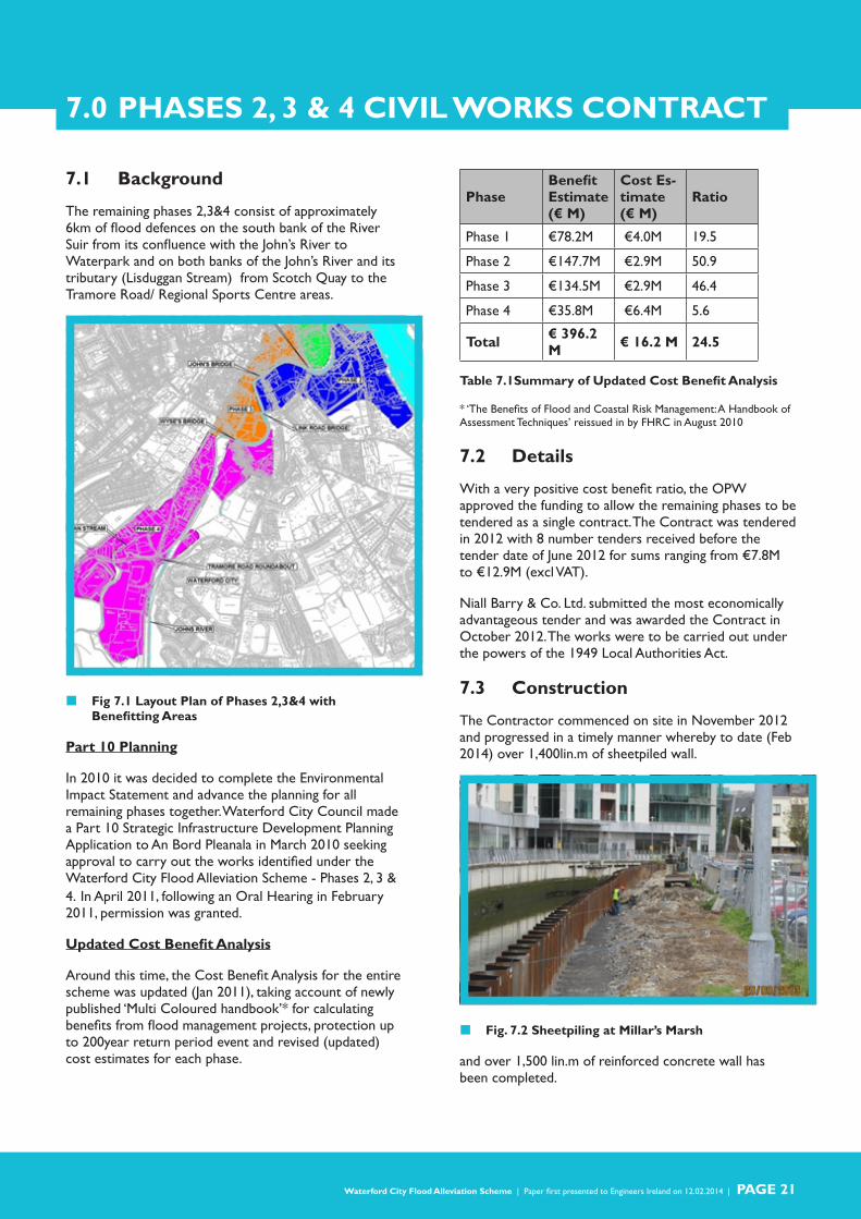
The remaining phases 2,3&4 consist of approximately 6km of flood defences on the south bank of the River Suir from its confluence with the John’s River to Waterpark and on both banks of the John’s River and its tributary (Lisduggan Stream) from Scotch Quay to the Tramore Road/ Regional Sports Centre areas.
� Fig 7.1 Layout Plan of Phases 2,3&4 with Benefitting Areas
Part 10 Planning
In 2010 it was decided to complete the Environmental Impact Statement and advance the planning for all remaining phases together. Waterford City Council made a Part 10 Strategic Infrastructure Development Planning Application to An Bord Pleanala in March 2010 seeking approval to carry out the works identified under the Waterford City Flood Alleviation Scheme - Phases 2, 3 & 4. In April 2011, following an Oral Hearing in February 2011, permission was granted.
Updated Cost Benefit Analysis
Around this time, the Cost Benefit Analysis for the entire scheme was updated (Jan 2011), taking account of newly published ‘Multi Coloured handbook’* for calculating benefits from flood management projects, protection up to 200year return period event and revised (updated) cost estimates for each phase.
PhaseBenefit Estimate (€ M)
Cost Es-timate (€ M)
Ratio
Phase 1 €78.2M €4.0M 19.5
Phase 2 €147.7M €2.9M 50.9
Phase 3 €134.5M €2.9M 46.4
Phase 4 €35.8M €6.4M 5.6
Total € 396.2 M € 16.2 M 24.5
Table 7.1Summary of Updated Cost Benefit Analysis
* ‘The Benefits of Flood and Coastal Risk Management: A Handbook of Assessment Techniques’ reissued in by FHRC in August 2010
7.2 Details
With a very positive cost benefit ratio, the OPW approved the funding to allow the remaining phases to be tendered as a single contract. The Contract was tendered in 2012 with 8 number tenders received before the tender date of June 2012 for sums ranging from €7.8M to €12.9M (excl VAT).
Niall Barry & Co. Ltd. submitted the most economically advantageous tender and was awarded the Contract in October 2012. The works were to be carried out under the powers of the 1949 Local Authorities Act.
7.3 Construction
The Contractor commenced on site in November 2012 and progressed in a timely manner whereby to date (Feb 2014) over 1,400lin.m of sheetpiled wall.
� Fig. 7.2 Sheetpiling at Millar’s Marsh
and over 1,500 lin.m of reinforced concrete wall has been completed.

PAGE 22 | Gavin O’Donovan, BE CEng MIEI, Associate, RPS Consulting Engineers Ltd
� Fig. 7.3 Reinforced concrete wall in People’s Park
At the half way stage, the works are on programme to be completed within the 2 year contract period.
Challenges
There were a number of challenges encountered during the works which can be summarised as follows:
Restricted Working Space
There were significant restrictions on the available working space to carry out the works with many work sites confined to riverbanks between existing buildings and the river channels. The restricted access and limited working room has proved challenging with restrictions on the machinery and methodologies allowable to carry out the works.
� Fig. 7.4 Restricted Working Space for works on John’s River
Sheetpiling in close proximity to buildings
Driving sheetpiles on the river banks adjacent to existing buildings has also been challenging. Ground conditions proved to be as poor as predicted and therefore
vibration levels from all pilling work was minimal.
� Fig. 7.5 Sheetpiling on River Suir near existing buildings
7.3 Finishes
As per previous contracts the finishes were designed to suit the character of each area. Stone facing to floodwalls included sandstone (William St, Maritana Gate etc);
� Fig. 7.6 Sandstone finish to floodwalls in William St Properties
limestone (Waterpark, People’s Park, Tesco’s etc);
� Fig. 7.7 Limestone finish floodwalls in the People’s Park

Waterford City Flood Alleviation Scheme | Paper first presented to Engineers Ireland on 12.02.2014 | PAGE 23
and limestone faced concrete panels to exposed sheetpiles (Gasworks, Millar’s Marsh etc).
� Fig. 7.8 Masonry Faced Concrete Panels on Sheetpiled Wall at Millar’s Marsh
Work also includes the provision of over 1km of new dedicated cycle and walking path along the route old Tramore railway line connecting the city to the Tramore Road and Kilbarry Nature Park.
� Fig. 7.9 Construction of flood defences and cycle path along line of old railway.

PAGE 24 | Gavin O’Donovan, BE CEng MIEI, Associate, RPS Consulting Engineers Ltd
8.0 POST CONSTRUCTION BENEFITS
8.1 Urban Regeneration
As well as protecting the city from flooding from events up to the 200year return period (tidal areas) the works have provided an added benefit to the city by regenerating areas and improving the publics association with the cities rivers.
� Fig. 8.1 View (1) of Scotch Quay before works
� Fig. 8.2 View (1) of Scotch Quay after works
� Fig. 8.3 View (2) of Scotch Quay before works
� Fig. 8.4 View (2) of Scotch Quay after works
� Fig. 8.5 View (1) of Adelphi Quay before works
� Fig. 8.6 View (1) of Adelphi Quay before works
Waterford City Flood Alleviation Scheme | Paper first presented to Engineers Ireland on 12.02.2014 | PAGE 25
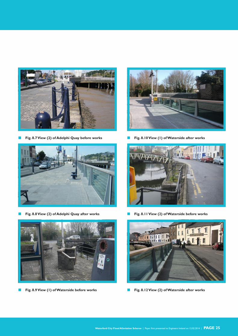
� Fig. 8.7 View (2) of Adelphi Quay before works
� Fig. 8.8 View (2) of Adelphi Quay after works
� Fig. 8.9 View (1) of Waterside before works
� Fig. 8.10 View (1) of Waterside after works
� Fig. 8.11 View (2) of Waterside before works
� Fig. 8.12 View (2) of Waterside after works

PAGE 26 | Gavin O’Donovan, BE CEng MIEI, Associate, RPS Consulting Engineers Ltd
� Fig. 8.13 View (3) of Waterside before works
� Fig. 8.14 View (1) of Waterside after works
� Fig. 8.15 View of Quay near Rice’s Bridge before works
� Fig. 8.16View of Quay near Rice’s Bridge after works
� Fig. 8.17 View (1) Merchant’s Quay before works
� Fig. 8.18View (1) Merchant’s Quay after works

Waterford City Flood Alleviation Scheme | Paper first presented to Engineers Ireland on 12.02.2014 | PAGE 27
� Fig. 8.19 View (2) Merchant’s Quay before works
� Fig. 8.20 View (2) Merchant’s Quay after works
8.2 Flood Event January 2014
A series of severe storms hit the Irish coast in early January 2014. Extreme water levels were experienced throughout the coastal areas of the country due to high astronomical tides combining with low atmospheric pressure and surge from storm force winds. Extreme water levels were also experienced in Waterford City with the flood level in the River Suir and the John’s River reaching a level above 2.8mOD Malin Hd in the city on both the 3rd and the 6th January.
� Fig. 8.21 Screen shot of readout from OPW gauge at Adelphi Quay.
Some lowlying areas in the city, including some properties but mostly roads, did experience some flooding from tidal waters overtopping the river banks. However, an even more extreme event was experienced in early February. Conditions similar to the January event resulted in water levels of over 3.0mOD in the River Suir and at high tide on the morning of February 3rd up to 40 properties in the Poleberry area where badly flooded.
� Fig. 8.22 Temporary flood protection measures at Poleberry (4th February 2014).
However, properties along the River Suir Quays and along Scotch Quay and Waterside on the John’s River that would, under such conditions, have been under water where mostly unaffected by the floodwaters. It is estimated that over 180 properties in these areas would have been flooded in the February event if not for the completed flood defence works.

PAGE 28 | Gavin O’Donovan, BE CEng MIEI, Associate, RPS Consulting Engineers Ltd
� Fig 8.23 Floodwaters against the Glass Floodwall at Waterside (Feb 2014)
All the lowlying areas affected by the flooding in January and February 2014 will also be protected on completion of the current Phases 2,3&4 Contract later this year (2014).
� Fig 8.24 Extract from Waterford News & Star 21st January 2014.

Waterford City Flood Alleviation Scheme | Paper first presented to Engineers Ireland on 12.02.2014 | PAGE 29
9.0 CONCLUSION
The completion of the Waterford City Flood Alleviation Scheme will see the city that has had a long history of flooding, protected from extreme flood events. Working on a project that has such a positive benefit to the community has been immensely satisfying for all involved. The successful delivery owes much to the excellent working relationship between the Employer, the Contractor, the Resident Engineering Staff and the Consulting Engineers and their ability to develop pragmatic solutions.
� Fig 9.1 Waterford City Flood Defences
9.1 Acknowledgements
The author gratefully acknowledges the support of the funding authorities throughout the project: Office of Public Works (Cian O Domhnaill and Cyril McCarthy) and Waterford City Council (Collette Byrne).
The author wishes to thank in particular John Nolan and Maura Phelan, Senior Executive Engineers, Waterford City Council who were central to the success of the project.
The author wishes to thank colleagues Roslyn McCarthy, Denis Cronin and Donal Courtney for their considerable input into the design of the works. The author also wishes to thank Kevin Power and Donal Lucey, Directors, RPS for the advice and guidance provided throughout the project.
9.2 Project Team
Funding Authorities:
» Office of Public Works (OPW)
» Waterford City Council (WCC)
Employer:
» Waterford City Council
Consulting Engineer & PSDP:
» RPS Consulting Engineers Ltd,
Phase 1 Contract:
» Contractor & PSCS: Niall Barry & Co. Ltd
» Resident Engineer: Mark McInerney
Phases 2 & 3 Advance Works Contract:
» Contractor & PSCS: BAM Civil Ltd
» Resident Engineer: Keith Hamm
Phases 2, 3 & 4 Contract:
» Contractor & PSCS: Niall Barry & Co. Ltd
» Resident Engineering Staff:
» Donal Lucey (Senior RE)
» Andrew Kennedy (RE)
» John Quigley (RE)
» Garret Clarke (Clerk of Works)

Gavin O’Donovan, BE CEng MIEI, Associate, RPS Consulting Engineers Ltd


![Legislative Assembly WEDNESDAY NOVEMBER€¦ · the Seventeen-mile Rocks passage on the Brisbane River being impassable except . 1718 Supply. [ASSEl\lBLY.] Supply. at certain stages](https://img.dokumen.tips/doc/110x75/5ea20272d7a41d1de12c5d8a/legislative-assembly-wednesday-november-the-seventeen-mile-rocks-passage-on-the.jpg)