Embed Size (px)
Citation preview
CITY OF BELLEVUE
UTILITIES DEPARTMENT
WATER ENGINEERING STANDARDS
JANUARY 2017
www.bellevuewa.gov/utilities_codes_standards_intro.htm

WATER ENGINEERING STANDARDS JANUARY 2017
WATER ENGINEERING STANDARDS JANUARY 2017
TABLE OF CONTENTS
CHAPTER W1 - GENERAL REQUIREMENTS
W1-02 GENERAL ............................................................................................................... W1 - 1
W1-02 DEFINITIONS .............................................................................................................. W1 - 1
W1-03 REFERENCES ............................................................................................................. W1 - 4
W1-04 GOVERNMENTAL AGENCY REQUIREMENTS .................................................... W1 - 4
W1-05 NO LEAD RULE .......................................................................................................... W1 - 4
CHAPTER W2 - PLAN SUBMITTAL
W2-01 GENERAL ............................................................................................................... W2 - 1
W2-02 DEVIATIONS .............................................................................................................. W2 - 1
W2-03 ERRORS AND OMISSIONS ....................................................................................... W2 - 1
W2-04 PLANS ............................................................................................................... W2 - 1
W2-05 AS-BUILT DOCUMENTATION ................................................................................ W2 - 6
CHAPTER W3 - WATER PLANNING/DESIGN STANDARDS
W3-01 PLANNING CRITERIA ............................................................................................... W3 - 1
W3-02 GENERAL DESIGN STANDARDS ........................................................................... W3 - 2
W3-03 VALVING ............................................................................................................... W3 - 4
W3-04 FIRE HYDRANTS ....................................................................................................... W3 - 5
W3-05 PIPE CLASS / PROTECTION / COVER .................................................................... W3 - 6
W3-06 CLEARANCES / OTHER UTILITIES ........................................................................ W3 - 7
W3-07 SLOPES ............................................................................................................... W3 - 8
WATER ENGINEERING STANDARDS JANUARY 2017
W3-08 CONNECTIONS TO EXISTING SYSTEM ................................................................ W3 - 8
W3-09 EASEMENTS W3 - 9
W3-10 SERVICES ............................................................................................................. W3 - 10
W3-11 BACKFLOW PREVENTION .................................................................................... W3 - 11
W3-12 LANDSCAPE WATER BUDGETING REQUIREMENTS ..................................... W3 - 12
W3-13 IRRIGATION SYSTEM DESIGN AND PERFORMANCE
REQUIREMENTS ...................................................................................................... W3 - 19
CHAPTER W4 - WATER MATERIALS
W4-01 GENERAL ............................................................................................................... W4 - 1
W4-02 WATER PIPE ............................................................................................................... W4 - 1
W4-03 POLYETHYLENE ENCASEMENT ........................................................................... W4 - 1
W4-04 FITTINGS ............................................................................................................... W4 - 1
W4-05 GALVANIZED IRON PIPE......................................................................................... W4 - 2
W4-06 COUPLINGS ............................................................................................................... W4 - 2
W4-07 ADAPTERS ............................................................................................................... W4 - 2
W4-08 BOLTS IN PIPING ....................................................................................................... W4 - 2
W4-09 FLANGE GASKETS .................................................................................................... W4 - 3
W4-10 GATE VALVE ............................................................................................................. W4 - 3
W4-11 VALVE BOX ............................................................................................................... W4 - 3
W4-12 VALVE OPERATING NUT EXTENSION ................................................................. W4 - 3
W4-13 BUTTERFLY VALVE ................................................................................................. W4 - 3
W4-14 CHECK VALVE .......................................................................................................... W4 - 4
W4-15 AIR AND VACUUM RELEASE VALVE ................................................................. W4 - 4
W4-16 PRESSURE REDUCING STATION ........................................................................... W4 - 4
WATER ENGINEERING STANDARDS JANUARY 2017
W4-17 LIDS, HATCHES AND COVERS - SLIP RESISTANCE .......................................... W4 - 5
W4-18 CITY-FURNISHED INDIVIDUAL PRESSURE
REDUCING VALVE (RESIDENTIAL) ...................................................................... W4 - 5
W4-19 CITY-FURNISHED INDIVIDUAL PRESSURE
REDUCING VALVE (MULTI-FAMILY OR COMMERCIAL) ................................ W4 - 5
W4-20 FIRE HYDRANT ......................................................................................................... W4 - 6
W4-21 HYDRANT GUARD POSTS ....................................................................................... W4 - 6
W4-22 METER SETTER ......................................................................................................... W4 - 6
W4-23 CORPORATION STOP ............................................................................................... W4 - 6
W4-24 METER BOX W ........................................................................................................... W4 - 7
W4-25 COPPER SERVICE PIPE............................................................................................. W4 - 7
W4-26 Not Used ............................................................................................................... W4 - 7
W4-27 PIPE INSULATION ..................................................................................................... W4 - 7
W4-28 CONCRETE BEDDING & BLOCKING ..................................................................... W4 - 7
W4-29 JOINT RESTRAINT .................................................................................................... W4 - 8
W4-30 REDUCED PRESSURE BACKFLOW ASSEMBLY ................................................. W4 - 8
W4-31 REDUCED PRESSURE DETECTOR ASSEMBLY ................................................... W4 - 8
W4-32 DOUBLE CHECK VALVE ASSEMBLY ................................................................... W4 - 8
W4-33 DOUBLE CHECK DETECTOR ASSEMBLY............................................................ W4 - 8
W4-34 BACKFLOW ASSEMBLY RESILIENT SEATED
SHUT-OFF VALVES ................................................................................................... W4 - 9
W4-35 BARRIER FENCE........................................................................................................ W4 - 9
W4-36 BEDDING AND BACKFILL ...................................................................................... W4 - 9
W4-37 STEEL CASING ......................................................................................................... W4 - 11
W4-38 CASING SPACER...................................................................................................... W4 - 12

WATER ENGINEERING STANDARDS JANUARY 2017
CHAPTER W5 - WATER METHODS OF CONSTRUCTION
W5-01 GENERAL CONSTRUCTION REQUIREMENTS .................................................... W5 - 1
W5-02 SURFACE WATER QUALITY................................................................................... W5 - 1
W5-03 LAYING DUCTILE IRON PIPE ................................................................................. W5 - 2
W5-04 POLYETHYLENE ENCASEMENT ........................................................................... W5 - 2
W5-05 LAYING GALVANIZED IRON PIPE ........................................................................ W5 - 2
W5-06 FIRE HYDRANT INSTALLATION ........................................................................... W5 - 3
W5-07 VALVE INSTALLATION ........................................................................................... W5 - 3
W5-08 AIR VACUUM INSTALLATION ............................................................................... W5 - 3
W5-09 VALVE BOX MARKER INSTALLATION ............................................................... W5 - 3
W5-10 SERVICE LINES.......................................................................................................... W5 - 4
W5-11 PRESSURE REDUCING STATION ........................................................................... W5 - 5
W5-12 CITY-FURNISHED INDIVIDUAL PRESSURE
REDUCING VALVE ................................................................................................... W5 - 5
W5-13 CONCRETE BLOCKING ............................................................................................ W5 - 5
W5-14 CONNECTION TO EXISTING WATER MAIN ....................................................... W5 - 6
W5-15 ORDER OF CONSTRUCTION ................................................................................... W5 - 7
W5-16 HYDROSTATIC TESTS ............................................................................................. W5 - 7
W5-17 DISINFECTION & FLUSHING OF WATER MAINS ............................................... W5 - 8
W5-18 PRECONSTRUCTION PHOTOS FOR CITY CONTRACTS .................................... W5 - 8
W5-19 UNDERGROUND UTILITIES .................................................................................... W5 - 9
W5-20 CONSTRUCTION ON EASEMENTS ........................................................................ W5 - 9
W5-21 DUST CONTROL ...................................................................................................... W5 - 10
W5-22 BARRIER FENCE...................................................................................................... W5 - 10
WATER ENGINEERING STANDARDS JANUARY 2017
W5-23 TRENCH EXCAVATION ......................................................................................... W5 - 10
W5-24 SHEETING & SHORING .......................................................................................... W5 - 11
W5-25 TRENCH DEWATERING ......................................................................................... W5 - 11
W5-26 BEDDING, BACKFILL AND COMPACTION ........................................................ W5 - 11
W5-27 TRENCHLESS EXCAVATION ................................................................................ W5 - 14
W5-28 ADJUST EXISTING STRUCTURE TO GRADE ..................................................... W5 - 14
W5-29 ABANDONING FACILITIES ................................................................................... W5 - 15
W5-30 LAWN REMOVAL AND REPLACEMENT ............................................................ W5 - 16
W5-31 BORING UNDER ROOTS ........................................................................................ W5 - 16
W5-32 HIGHWAY AND RAILROAD CROSSINGS ........................................................... W5 - 16
W5-33 BORING AND JACKING STEEL CASING............................................................. W5 - 17
W5-34 WORKING WITH ASBESTOS CEMENT PIPE ...................................................... W5 - 17
W5-35 ASBESTOS CEMENT WATER MAIN CROSSINGS ............................................. W5 - 17
W5-36 VAULT INSTALLATION ......................................................................................... W5 - 18
CHAPTER W6 - SUMMARY OF UNDERGROUND FIRE SYSTEM INSTALLATION
REQUIREMENTS FOR COMMERCIAL/MULTI-FAMILY PROJECTS
(FOR SERVICES GREATER THAN 2 INCHES IN DIAMETER)
W6-01 GENERAL ............................................................................................................... W6 - 1
W6-02 PERMITTING .............................................................................................................. W6 - 1
W6-03 INSTALLATION ......................................................................................................... W6 - 1
W6-04 INSPECTIONS ............................................................................................................. W6 - 1
W6-05 MATERIALS & CONSTRUCTION REQUIREMENTS ............................................ W6 - 2
WATER ENGINEERING STANDARDS JANUARY 2017
APPENDICES
APPENDIX W-1
WATER WORKS STANDARD DETAILS ....................................................................... A(W1 - 1)
APPENDIX W-2
DRAFTING STANDARDS ................................................................................................ A(W2 - 1)
APPENDIX W-3
SAMPLE TITLE BLOCK ................................................................................................... A(W3 - 1)
APPENDIX W-4
WATER APPROVED MATERIALS LIST ........................................................................ A(W4 - 1)
APPENDIX W-5
WATER WORKS REFERENCE STANDARDS .................................................. A(W5 – 1)
WATER ENGINEERING STANDARDS JANUARY 2017
CHAPTER W1 - GENERAL REQUIREMENTS
TABLE OF CONTENTS
W1-01 GENERAL ............................................................................................................. W1 – 1
W1-02 DEFINITIONS .......................................................................................................... W1 - 1
W1-03 REFERENCES ......................................................................................................... W1 - 4
W1-04 GOVERNMENTAL AGENCY REQUIREMENTS ................................................ W1 - 4
W1-05 NO LEAD RULE....................................................................................................... W1 – 4
WATER ENGINEERING STANDARDS JANUARY 2017
W1 - 1
CHAPTER W1 - GENERAL REQUIREMENTS
W1-01 GENERAL
These Engineering Standards set forth minimum standards for the planning, design, and
construction of water facilities.
The Water Utility Code, part of Chapter 24.02 of the Bellevue City Code, adopted April 3, 1995,
is the basis for these Engineering Standards.
These Standards do not include design of special facilities, such as Pump Stations or Reservoirs.
These special facilities require unique design requirements and will be subject to individual review
by the Utility.
Although these Standards are intended to apply to physical development within the Utility, the
Standards will not apply for all situations. Compliance with these Standards does not relieve the
designer of the responsibility to apply conservative and sound professional judgment. These are
minimum Standards and are intended to assist, but not substitute for competent work by design
professionals. The Utility may at its sole discretion due to special conditions and/or
environmental constraints, require more stringent requirements than would normally be required
under these Standards.
W1-02 DEFINITIONS
The following terms as used in this document shall be defined and interpreted as follows:
“ADA”
Americans With Disabilities Act (ADA) of 1990. 42 USC 12101 et seq with implementing
regulations. See ADA Home Page: http://www.ada.gov
“Downtown (DNTN)”
That area of Bellevue generally bounded by Main Street, NE 12th Street, 100th Avenue
NE, and 112th Avenue NE.
“Contractor”
The person, partnership, firm or corporation contracting to do the work under these
Documents. The term shall also include the Contractor's agents, employees and
subcontractors.
“Details or Additional Drawings”
All details or drawings prepared to further explain or amplify the plans, or for the revision
of the same, all as herein provided.
“Developer”
Any individual, company, partnership, joint venture, corporation, association, society or
group that has made, or intends to make, application to the City for permission to construct
a water system connection, or extension, to the City’s water system.
WATER ENGINEERING STANDARDS JANUARY 2017
W1 - 2
“Engineer”
The City of Bellevue Utilities Engineer or his duly authorized assistants, which includes
Chief Engineer, Project Engineer, Consultant Engineer and/or Inspectors.
“Equipment”
The machinery, accessories, appurtenances and manufactured articles to be furnished
and/or installed under the Project.
“Material or Materials”
These words shall be construed to embrace machinery, manufactured articles, materials of
construction (fabricated or otherwise) and any other classes of material to be furnished in
connection with the Project.
“Multiple Use Building”
A building, or set of buildings with multiple tenant spaces, not including residential-only
structures, served by a shared domestic water service. Ex. Strip malls.
“Or Equal”
Any manufactured article, material, method, or work which, in the opinion of the Engineer,
is equally desirable or suitable for the purposes intended in these standards as compared
with similar articles specifically mentioned herein.
“Plan”
All official drawings or reproductions of drawings made or to be made pertaining to the
work provided for in the permit or developer extension agreement.
“Plumbing Code”
The Uniform Plumbing Code as adopted by the COB City Council, together with
amendments, additions and exemptions per Municipal Code 23.60.
“Premise Isolation”
A method of protecting the public water system by installation of approved air gaps or
approved backflow prevention assemblies at or near the service connection or alternative
location acceptable to the purveyor to isolate the consumer's water system from the
purveyor's distribution system.
“Project”
The structure or improvement to be constructed in whole or in part.
WATER ENGINEERING STANDARDS JANUARY 2017
W1 - 3
“Reference Specifications”
Reference specifications shall mean the technical specifications of other agencies
incorporated or referred to herein.
“Specifications”
The specifications shall mean the prescribed directions, requirements, explanations, terms
and provisions pertaining to the various features of the work to be done, or manner and
method of performance. They also include directions, requirements, and explanations as
set forth on the plans.
“Standard Details”
City of Bellevue Utilities Department standard detail drawings.
“Standard Specification”
“2010 Standard Specifications for Road, Bridge and Municipal Construction”, English
edition, Washington State Department of Transportation and the American Public Works
Association including all amendments.
“Unapproved Auxiliary Supply”
A water supply (other than the purveyor's water supply) on or available to the consumer's
premises that is either not approved for human consumption by the health agency having
jurisdiction or is not otherwise acceptable to the purveyor. Sites with unapproved auxiliary
supplies require premise isolation.
“Words and Phrases”
Whenever the words, “as directed”, ‘as required’, “as permitted”, or words of like effect
are used, it shall be understood that the direction, requirement or permission of the
Engineer is intended. The words, “sufficient”, “necessary”, “proper”, and the like shall
mean sufficient, necessary or proper in the judgment of the Engineer. The words,
“approved”, “acceptable”, “satisfactory”, or words of like import shall mean approved by
or acceptable to the Engineer.
“Work”
The work necessary to manufacture and deliver machinery, equipment and material and/or
the furnishing of all labor, tools, material, equipment, construction equipment, working
drawings, where required, and other, necessities for the construction or erection of the
structures shown and called for in the plans, specifications and permit/Developer
Extension Agreement, and the act of constructing or erecting said structures complete.
WATER ENGINEERING STANDARDS JANUARY 2017
W1 - 4
W1-03 REFERENCES
Wherever references are made to the standards, specifications, or other published data of the
various national, regional, or local organizations, such organizations may be referred to by their
acronym or abbreviation only. As a guide to the user, the following acronyms or abbreviations
which may appear, shall have the meanings indicated herein:
AASHTO American Association of the State Highway and Transportation Officials.
ANSI American National Standards Institute, Inc.
WSDOT Washington State Department of Transportation
APWA American Public Works Association
ASTM American Society for Testing and Materials
AWWA American Water Works Association
DOH Department of Health
UPC Uniform Plumbing Code
WAC Washington Administrative Code
W1-04 GOVERNMENTAL AGENCY REQUIREMENTS
All construction on City, County or State roads or right-of-way shall be done in accordance with
the agency's standards and requirements and in accordance with the franchise and/or permit
requirements. The Contractor is responsible to determine these requirements prior to construction.
Where conflict exists between these Standards and permit requirements, the most stringent permit
requirements shall take precedence.
Metal lids, hatches and manhole covers located in sidewalks, crosswalks or other pedestrian areas
must comply with ADA requirements and have a slip resistant surface.
W1-05 THE REDUCTION OF LEAD IN DRINKING WATER ACT
New USEPA Regulations Regarding Lead-free Water System Materials
Effective January 4, 2015
The Reduction of Lead in Drinking Water Act was enacted on January 4, 2011, to amend Section
1417 of the Safe Drinking Water Act, which covers the use and introduction into commerce of lead
pipes, plumbing fittings or fixtures, solder and flux. The Reduction of Lead in Drinking Water Act
changes the Safe Drinking Water Act definition of “lead free.” All water system materials
installed under this Contract shall comply with revised Act. The Contractor shall provide
Manufacturer’s Certificate of Compliance in accordance with the current edition of the
Washington State Standard Specifications for all water system materials to be used. The
Certificate must clearly state that the materials furnished comply with "lead-free” requirements of
the revised Safe Drinking Water Act.
END OF CHAPTER W1
WATER ENGINEERING STANDARDS JANUARY 2017
CHAPTER W2 - PLAN SUBMITTAL
TABLE OF CONTENTS
W2-01 GENERAL ........................................................................................................... W2 - 1
W2-02 DEVIATIONS ..................................................................................................... W2 - 1
W2-03 ERRORS AND OMISSIONS .............................................................................. W2 - 1
W2-04 PLANS ................................................................................................................. W2 - 1
W2-05 AS-BUILT DOCUMENTATION ....................................................................... W2 - 6
WATER ENGINEERING STANDARDS JANUARY 2017
W2 - 1
CHAPTER W2 - PLAN SUBMITTAL
W2-01 GENERAL
Following these standards to design the water system will help ensure a timely review of the
proposed project and keep review costs to a minimum.
W2-02 DEVIATIONS
W2-02.1 General
The Developer may propose a deviation from the Standards. A non-standard system may
take longer to review resulting in increased processing costs. The Developer
acknowledges these risks when submitting a non-standard system for review.
W2-02.2 Deviation Criteria
Requests for deviations which are site or project specific shall be reviewed by the Utilities
Technical Committee (Engineering Team). The City’s decision to grant, deny, or modify
the proposed deviation shall be based upon evidence that the deviation request meets the
following criteria:
A. The change will achieve the intended result through a comparable or even superior
design; and
B. The change will not adversely affect safety and/or operation; and
C. The change will not adversely affect maintainability.
W2-03 ERRORS AND OMISSIONS
Any errors or omissions in the approved plans or information used as a basis for such approvals
may constitute grounds for withdrawal of any approvals and/or stoppage of any or all of the
permitted work, as determined by the City. It shall be the responsibility of the Developer to show
cause why such work should continue, and make such changes in plans that may be required by
the City before the plans are re-approved.
W2-04 PLANS
W2-04.1 General
Utility plans submitted for review shall meet “Boundary & Topographic Survey” and “Site
Plan B” requirements. Current copies of these requirements are available at the City Hall
Permit Center. The Utilities representative at the Permit Center will determine which
requirements, if any, are not applicable to the proposed project.
WATER ENGINEERING STANDARDS JANUARY 2017
W2 - 2
W2-04.2 Submittal Standards
Water, sanitary sewer and storm drainage designs (complete plan and profile) shall be on
separate plan sheets, although alignments of all Utilities shall be shown on each utility
plan. Plan sets for all three Utilities can be combined for small projects. Designs for water
and sewer can be combined on the same plan sheets if plan scale is 1"=10', 1"=20', or
1"=30'. Contact the Utility representative in the Permit Center for approval to combine
plans.
Site plans shall include:
1. Title Block - Border and title block shall conform to standard City of
Bellevue format. Include Section – Township – Range, grid number, and
project site address in the lower right hand corner. See Appendix W-3.
2. Project Name Utility Extension (UE) Permit Number – provide if
applicable.
3. Engineering Plans - Plan, and detail sheet(s) for the proposed water system.
a. Plan View:
i. List pipe length, size, and material alongside of pipe, e.g. 150
L.F. - 8" PVC. Pipe material can be listed in a general note in
lieu of listing along pipe.
ii. Pipe length is to be based on horizontal distance between
appurtenances (e.g. valves, fittings).
b. Profile View
i. List pipe length, size, and material to 4 decimal places (ft per
ft). Pipe material can be listed in a plan note in lieu of listing
on profile.
4. Scale - Be consistent, and indicate your scale on each sheet using a bar
symbol (for plan reproduction integrity). Drawings are to be at a scale of
1"=10', 1"=20', or 1"=30' for combined utility plans. Drawings at 1"=40' or
1"=50' scale shall show utility plans on separate sheets. Architectural scales
for utility drawings will not be accepted. If the scale results in more than
three pages of plan sheets, a cover sheet showing the entire project site (at a
smaller scale) shall be provided.
5. North Arrow - Include on all plan view drawings. Where possible, north
arrow shall face up and/or to the right hand side of plan sheet.
6. Datum - Show both horizontal NAD-83 (NSRS 2011) and vertical (NAVD
88) control points.
WATER ENGINEERING STANDARDS JANUARY 2017
W2 - 3
7. Vicinity Map - Include on the plan for each utility. The vicinity map covers
the project site and surrounding streets and property within a minimum of
600' of the site.
Plan submittals shall conform to Development Services “Standards for Plans and
Drawings,” including the following:
1. Line Types – Use line types that clearly distinguish existing utilities from
new; new facilities and call-outs for new facilities should be a heavier line
type.
2. Drawing Quality - The drawing should be easy to read, with all lines and
letters dark enough to provide good contrast with the paper.
3. Drafting Media - Plans sheets shall be on 24"x 36"or 22" x 34" bond paper.
4. Drafting Standards - Plotting shall be on bond paper with a non-smudging,
ink or ink-like media. Pencil drawings (including corrections or alterations)
will not be accepted.
5. Drafting Standards/Symbols shall conform to Washington State APWA
Chapter CAD Standards. See Appendix W-2. Lettering shall be done with
“Leroy-style” font (SIMPLEX font if using AutoCAD).
6. Text Height:
a. Text identifying existing features shall be 0.08" in height (Leroy 80
template).
b. Text identifying street names shall be 0.24" in height (Leroy 240
template).
c. Text for instructions and call outs for proposed facilities shall be 0.
12" in height (Leroy 120 template).
7. Stationing - On plans with more than one sheet, stationing shall proceed
from left to right or from bottom to top.
8. Copies of Plans - Blueline or blackline prints and photocopies are
acceptable. Brownline prints and microfilm copies of plans will not be
accepted.
9. Type of Paper for Plan Copies - Blueprint quality or standard drafting
paper. Tissue paper, graph paper, poster board, cardboard, and similar
materials will not be accepted.
W2-04.3 Water General Plan Notes
WATER ENGINEERING STANDARDS JANUARY 2017
W2 - 4
The following is a listing of General Notes that should be incorporated on the first water
plan sheet. All the notes on the list may not pertain to every project. The Developer
should include only those notes that are relevant to the project and may omit non-relevant
notes.
However, do not renumber the remaining General Notes. If additional notes are needed for
specific aspects, they should be added after the General Notes.
Water General Notes:
1. All work shall conform to the 2017 City of Bellevue Utility Engineering Standards
and the Developer Extension Agreement.
2. All pipe shall be ductile iron class 52 unless otherwise shown.
3. All pipe and fittings not to be disinfected in place shall be swabbed with 1%
available chlorine solution prior to installation.
4. The new water main shall be connected to the existing system only after new main
is pressure tested, flushed, disinfected and satisfactory bacteriological sample
results are obtained and received by the City Inspector. See Standard Detail W-9.
5. After disinfecting the water main, dispose of chlorinated water by discharging to
the nearest operating sanitary sewer.
6. Water main shut-off shall be coordinated with the Water Operations Division for
preferred timing during flow control conditions. Water main shut-offs shall not be
scheduled to take place on Fridays, or on the five days before nor one day after a
City holiday, unless otherwise approved by the Utility.
7. The locations of all existing utilities shown hereon have been established by field
survey or obtained from available records and should therefore be considered
approximate only and not necessarily complete. It is the sole responsibility of the
contractor to independently verify the accuracy of all utility locations shown, and to
further discover and avoid any other utilities not shown hereon which may be
affected by the implementation of this plan.
8. Deflect the water main above or below existing utilities as required to maintain 3 ft.
minimum cover and 12 inch minimum vertical clearance between utilities unless
otherwise specified.
9. Wrap all ductile iron pipe and adjacent valves and fittings with 8-mil. polyethylene
conforming to AWWA C105.
10. The water main shall be installed only after the roadway subgrade is backfilled,
graded and compacted in cut and fill areas.
11. Trench backfill and surface restoration of existing asphalt pavement shall be as
WATER ENGINEERING STANDARDS JANUARY 2017
W2 - 5
required by the right-of-way use permit.
12. All fittings shall be blocked per Standard Details unless otherwise specified.
13. All services shall be 1" x 1" per Standard Details unless otherwise specified.
Adaptors for 3/4” meters shall be used where applicable.
14. When working with asbestos cement pipe, the Contractor is required to maintain
workers’ exposure to asbestos material at or below the limit prescribed in WAC
296-62-07705.
15. Call 1-800-424-5555, or 811, 72 hours before construction for utility locations.
16. Uniform plumbing code requires the installation of privately owned and operated
pressure reducing valves where the operating pressure exceeds 80 psi.
17. The Contractor shall use a vacuum street sweeper to remove dust and debris from
pavement areas as directed by the Engineer. Flushing of streets shall not be
permitted without prior City approval.
18. Before commencement of trenching, the Contractor shall provide catch basin
inserts for all catch basins that will receive runoff from the project site. The
Contractor shall periodically inspect the condition of all inserts and replace as
necessary.
19. Abandonment of existing water services shall be accomplished as follows:
(See W5-29 Abandoning Facilities for other facility abandonment)
a. Remove existing service saddle from water main and replace with new
stainless steel repair band, Romac SS2, Ford Service Saddle FC101, CC
threaded saddle and a CC thread brass plug, or approved equal (will not
be required when water main is to be abandoned).
b. Remove and dispose of existing setter and meter box.
c. Cap or crimp (if copper) existing service line to be abandoned in place,
each end.
d. Return existing meter to City of Bellevue Utilities Inspector.
20. Where new utility line crosses below an existing AC main, the AC pipe shall be
replaced with DI pipe to 3 feet past each side of the trench as shown on Standard
Detail W-8. Wrap DI pipe and couplings with 8-mil polyethylene conforming to
AWWA C105. Alternatively, where directed by the Engineer, the trench shall be
backfilled with controlled density fill (CDF, aka flowable fill) from bottom of
trench to the invert of the AC main.
21. Avoid crossing water or sewer mains at highly acute angles. The smallest angle
WATER ENGINEERING STANDARDS JANUARY 2017
W2 - 6
measure between utilities should be 45 to 90 degrees.
22. Where water main crosses above or below sanitary sewer, one full length of water
pipe shall be centered for maximum joint separation.
23. At points where existing thrust blocking is found, minimum clearance between the
concrete blocking and other buried utilities or structures shall be 5 feet.
24. Workers must follow confined space regulations and procedures when entering or
doing work in COB owned confined spaces. Completed Permit must be given to
the Utilities inspector prior to entry.
25. Manholes, catch basins and vaults are considered to be permit-required confined
spaces. Entry into these spaces shall be in accordance with Chapter 296-809 WAC.
26. When work is to occur in easements, the Contractor shall notify the easement
grantor and Bellevue Utilities in writing a minimum of 48 hours in advance of
beginning work (not including weekends or holidays). Failure to notify grantor and
Bellevue Utilities will result in a Stop Work Order being posted until the matter is
resolved to the satisfaction of Bellevue Utilities. A written release from the
easement grantor shall be furnished to the Utilities Inspector prior to permit sign-
off.
27. The Contractor shall restore the Right-of-Way and existing public utility
easement(s) after construction to a condition equal or better than condition prior to
entry. Contractor shall furnish a signed release from all affected property owners
after restoration has been completed.
W2-05 AS-BUILT DOCUMENTATION
For all water projects the Developer or City Department responsible for the project shall
provide as-built plans at completion of the project.
W2-05.1 General Standards
As-built plans shall be based on field survey information. All survey work shall be
performed under the supervision of a Professional Land Surveyor registered in the State of
Washington.
Horizontal locations shall be recorded to within one tenth (0.1’) of a foot. Rim and invert
elevations shall be recorded to within one one-hundredth (0.01’) of a foot.
All pipe lengths and dimensions are based on horizontal distances, unless slope is too steep
to measure horizontal distance, inspector should note that length is “slope distance”.
References/dimensions from right-of-way centerline for utility features in the public right-
of-way, or from property line for utility features located within easements shall be
recorded.
WATER ENGINEERING STANDARDS JANUARY 2017
W2 - 7
As-built information shall be recorded on plan and profile views of the contract drawings.
The profile view shall note any changes from the design finished grade over each pipe line.
Items not built shall be crossed out. Changes to design attributes (elevations, pipe lengths,
etc.) shall have a strikethrough or be crossed out and relabeled in bold font.
New assets (pipes, structures, etc.) shall be drawn in bold linetype to differentiate from
existing assets. Where new pipes connect to existing structures the Utility Asset numbers
of those structures shall be noted on the drawing. Asset numbers can be obtained from the
City’s GIS data download webpage.
Asset ownership changes (e.g. City owned to Private or other agency and vice-versa) shall
be clearly noted. Easements boundaries and recording numbers shall be recorded if
obtained.
All as-built drawing sheets must have an “As-Built” or “Record Drawing” stamp block
with any appropriate disclaimers affixed.
The AutoCAD files shall include all plans, profiles, notes, and details of the water
improvements
W2-05.1(a) General CAD Standards
All AutoCAD “DWG” files are to utilize NAD_1983_HARN_StatePlane_Washington
North Zone (FIPS 4601) coordinate system and the City of Bellevue NAVD 1988 vertical
datum. Both must state on the drawings as the datums used.
Survey shall be located and field tied to at least two (2) City of Bellevue Survey Control
Network monuments. Topographic elevations shall be referenced to City of Bellevue
vertical control benchmarks. Survey Control Data Cards and Survey Benchmark Reports
are available on-line at http://www.bellevuewa.gov/surveycontrol/, or from the Survey
staff (425-452-4385).
Sample Title Block with north arrow, scale, vicinity map, etc. are predefined in
Appendix D-3.
Block names, layer names, colors, and linetypes are predefined in Appendix D-5.
All digital line work must be geometrically correct, topologically clean without
slivers, dangles, undershoots or inappropriate breaks. Polygon features drawn as
polylines must properly close without gaps.
Each AutoCAD “DWG” file shall be prepared in Model space and UCS must be set
to “World” then “Plan”
XREF’s are not allowed in the final AutoCAD “DWG” file delivery to the City.
The standard insertion scale shall be feet.
No blocks shall be “exploded”
The standard text font shall be “Simplex”

WATER ENGINEERING STANDARDS JANUARY 2017
W2 - 8
All drawing units shall be English.
W2-05.1(b) Submittals
The AutoCAD files shall include all plans, profiles, notes, and details of the surface water
improvements.
All as-built sheets must be submitted both electronically and on print:
Digital as-built files are to be saved in AutoCAD version 2011 or newer and in
“DWG” file format.
The "DWG" file(s) shall be submitted on CD ROM or via email.
Each as-built sheet shall be plotted and submitted on full-size (22” x 34” or 24” x
36”) bond paper.
W2-05.2 Required Information
Mains: Length (center of fitting to center of fitting), diameter, material, zone, class of
pipe, type of joint restraint (if any), depth, name of pipe manufacturer, note
“fireline”, if applicable. Show all private systems going (e.g. to apartments,
condominiums, commercial sites, joint-use, single family). . Label private
system components as “PRIVATE SYSTEM”
Valves: Size, type (gate, butterfly, etc.), joint type (mechanical joint, etc.)
Fittings: Call-outs in order, # of each, diameter, fitting, joint type (e.g. 2 – 8” 45° bend,
M.J.).
Services: Size, show location on plan.
Hydrants: Distance from valve to hydrant, depth of bury (e.g., 5’ bury).
END OF CHAPTER W2
WATER ENGINEERING STANDARDS JANUARY 2017
CHAPTER W3 - WATER PLANNING/DESIGN STANDARDS
TABLE OF CONTENTS
W3-01 PLANNING CRITERIA................................................................................... W3 - 1
W3-02 GENERAL DESIGN STANDARDS ............................................................... W3 - 2
W3-03 VALVING ........................................................................................................ W3 - 4
W3-04 FIRE HYDRANTS ........................................................................................... W3 - 5
W3-05 PIPE CLASS / PROTECTION / COVER ........................................................ W3 - 6
W3-06 CLEARANCES / OTHER UTILITIES ............................................................ W3 - 7
W3-07 SLOPES ............................................................................................................ W3 - 8
W3-08 CONNECTIONS TO EXISTING SYSTEM .................................................... W3 - 8
W3-09 EASEMENTS ................................................................................................... W3 - 9
W3-10 SERVICES...................................................................................................... W3 - 10
W3-11 BACKFLOW PREVENTION ........................................................................ W3 - 11
W3-12 LANDSCAPE WATER BUDGETING REQUIREMENTS ......................... W3 - 12
W3-13 IRRIGATION SYSTEM DESIGN AND PERFORMANCE
REQUIREMENTS .......................................................................................... W3 – 19
WATER ENGINEERING STANDARDS JANUARY 2017
W3 - 1
CHAPTER W3 - WATER PLANNING/DESIGN STANDARDS
W3-01 PLANNING CRITERIA
W3-01.1 Serve to Extreme of Property
Ensure adjacent properties can be provided water service (extend to extreme of property with
adequate capacity and pressure)
W3-01.2 Demand Projections
Demand projections are taken from Water System Plan.
A. Unit Demands
Single Family - 84 Gallons per Capita per Day (GPCD)
Multi-family - 75 GPCD
Commercial - 32 GPCD
Hotel/Motel - 50 GPCD
B. Population Densities
2.80 people per single family unit
1.90 people per multi-family unit
1.5 people per hotel/motel room
C. Peaking Factors
Maximum Day Demand (MDD) = Average Day Demand (ADD) x 2.00
Peak Hour Demand (PHD) = Maximum Day Demand (MDD) x 3.00
W3-01.3 System Parameters
A. Water velocity in mains - velocities shall not exceed 10 feet per second during
highest demand including fireflow.
B. Distribution System Pressures (Measured at ground elevation at the customers
meter):
Desirable Minimum 50 psi
Maximum 80 psi
Allowable Minimum 43 psi
Maximum 125 psi
WATER ENGINEERING STANDARDS JANUARY 2017
W3 - 2
Minimum 30 psi is allowed for existing systems.
Individual pressure reducing valves are required on all services when water
pressure exceeds 80 psi.
During fire suppression events, the water system must be able to provide 20-
psi minimum pressure at ground level at all points throughout the distribution
system. The water system must be able to provide this minimum pressure
under fire-flow conditions plus the MDD rate when all equalizing and fire flow
storage is depleted (WAC 246-290-230(6)).
C. Reservoir Replenishment - Facilities (i.e. transmission mains, pump stations) shall
be sized to enable storage facilities to be refilled within 3 days after an emergency
or major fire.
W3-01.4 Fireflow Requirements
. Fireflow requirements shall be as determined by either City of Bellevue or King County Fire
Marshal.
A. The Utility will determine available fireflow using its computer simulated model.
B. Minimum system pressure during fireflow analysis is 20 psi at all service
connections and 5 psi where there are no service connections.
W3-02 GENERAL DESIGN STANDARDS
A. Each fitting/valve shall have attachment type listed (e.g. FL, MJ, FL x MJ, etc.).
B. List pipe length (from center-of-fitting to center-of-fitting), size, and material
alongside of each pipe, e.g. 150 L.F. - 8" D.I. Pipe material can be listed in a general
note in lieu of listing along each pipe.
C. Indicate type of pavement restoration required by right-of-way authority having
jurisdiction (if working in existing streets).
D. Dimension existing and new main locations from right-of-way line and/or property
line, or label stations and offsets.
E. Blocking - Reference Standard Details
- At vertical bends, pipe shall be restrained a minimum of 36 feet
(2 joints) from each side of bend. Reduced-size concrete blocks
shall be installed at bends per Standard Detail W-2. No change
in pipe direction or diameter shall occur within 36 feet of the
vertical bend. In addition, bends, tees, reducers, etc., beyond
the 36-foot limit, shall be restrained with standard blocking per
Standard Detail W-1 and W-3. Where these criteria cannot be
WATER ENGINEERING STANDARDS JANUARY 2017
W3 - 3
met, plans should call for vertical blocking without joint
restraint per Standard Detail W-3, or a restraint method should
be designed and detailed on the plan.
- Check if special blocking or joint restraint designs are necessary
(e.g. poor soil, conflicting utility, etc.).
- Show all blocking on any detail drawing that shows vertical
bends.
- See Appendix W-4 - Approved Materials List for joint restraint
methods, other than concrete blocking.
F. Check if system may require additional looping (i.e. eliminate dead end lines).
G. To assure compatibility with existing system, check with Utility Development
Division to determine hydraulic gradients.
H. Drawings shall reference distance to nearest existing valve and/or hydrant from new
point of connection to existing water main.
I. Check with local jurisdiction for necessary permitting requirements.
J. Provide temporary 2" blow off assemblies for testing and disinfection of new water
mains (where hydrants are not available). Place blow-off at high end of line, where
possible.
K. Cap end of existing water lines to be abandoned as follows:
- Asbestos cement lines: use end cap coupling.
- Cast or ductile iron lines: use MJ cap or plug.
L. Minimum water main size
- 8" minimum when serving fire hydrants.
- 6" minimum may be used in localized conditions where fire hydrants are
served by looped lines, subject to Utility approval.
- 4" minimum shall be used to serve water to end of cul-de-sac when no future
extension is required.
M. Pressure reducing station plans should show location of pressure relief discharge pipe
and discharge point of floor drain piping (drain to daylight). Pressure relief discharge
pipe shall be shown at a location that will not be subject to damage or erosion during
discharge of water.
WATER ENGINEERING STANDARDS JANUARY 2017
W3 - 4
N. All water vaults (water service, backflow assembly, pressure reducing station, etc.)
shall include designs for floor drain piping draining to daylight, or, if daylight is not
feasible, to the storm system. Discharge point of vault floor drains shall be shown on
the plan. Where vault floor drain cannot drain to daylight or the storm system, consult
with the City during project design review to determine the best alternative.
Exception: Outside-installed Reduced Pressure Backflow Assemblies (RBPA) shall
be installed in above ground enclosures. The following drain requirements shall apply
to enclosures. RPBA shall not be installed in vaults. Each enclosure design shall be
as approved by the City. Floor drains for RPBA shall not connect to closed storm
drain systems. All RPBA enclosures shall be provided with a bore sighted daylight
drain. This bore sighted drain to daylight shall be clearly visible end to end, sized to
meet the flow requirements of the RPBA relief vent.
O. Placement of surface appurtenances (manhole lids, water valve lids, etc.) in tire track
of traffic lanes shall be avoided whenever possible. Meter vaults shall be located
outside the sidewalk whenever possible.
P. Service connections or water utility distribution system piping shall not be used for
grounding of electrical systems or for the maintenance, integrity or continuity of any
grounding attachment or connection.
Q. Manufacturer’s certification of testing and accuracy shall be provided for all
commercial meter installations.
W3-03 VALVING
A. 600' maximum distance between valves on distribution mains, except, in Downtown
(DNTN), maximum valve spacing shall be 200'.
B. Provide a valve at each end of an easement.
C. At water main intersections, valves shall be placed on 4 out of 4 legs at each cross, and
3 out of 3 legs at each tee (unless tapping an existing water main).
D. For all fire service connections greater than 3 inches in diameter, isolation valves shall
be installed on all legs of the tee. Tapping Tees are not allowed for fire service
connections greater than 2 inches in diameter.
E. For all domestic water service connections greater than 2 inches in diameter, isolation
valves shall be installed on all legs of the tee. Tapping Tees are not to be used for
domestic service connections greater than 2 inches in diameter.
F. Additional valving may be required for area isolation.
G. Combination Air/Vacuum with vacuum check valves shall be installed at local high
points in the water main.
WATER ENGINEERING STANDARDS JANUARY 2017
W3 - 5
W3-04 FIRE HYDRANTS
The following information is provided as a guideline to be used during design. The final number of
hydrants and their location shall be approved by the City of Bellevue or King County Fire Marshal.
A. Guard posts are to be used only in parking lots when no curbs are present or in
exposed areas in parking lots.
B. Fireline/hydrant run over 50' in length must be 8" (terminate with tee, plug and
hydrant assembly).
C. Fire hydrant location:
Single-family residential: Spacing = 500' apart. Coverage =250' from front
property line of the main body of a lot.
Multi-family/commercial: As determined by the fire marshal.
Exceptions: On arterial streets without residential access
(through traffic only), maximum hydrant spacing
shall be 1000'.
On dead-end streets, reduce single-family residential
spacing to be 400’ apart.
D. 3' minimum clearance shall be provided around outside of hydrant for operation.
Provide 5’ horizontal clearance from the outside of the hydrant to concrete walls,
structures, utility poles and above grade electrical enclosures.
E. Where feasible, fire hydrants shall be installed on the same side of the street as the
water main.
F. Private Fire Hydrants:
When a fire hydrant is to be installed on commercial, multi-family and institutional
property, outside of the right-of-way or designated public water utility easements, and
the fire hydrant is intended to provide fire protection for only that property, the fire
hydrant and the water line serving the fire hydrant shall be privately owned and
maintained by the benefiting property owner. Such water line and fire hydrant are
considered to be part of the benefiting property’s fire protection system and shall be
designated on the approved construction drawings and the Utility’s as-built drawings
as “PRIVATE” or “PVT”.
The private water line that serves the private fire hydrant and/or the fire sprinkler
system shall be owned by the benefitting property owner beginning immediately
downstream of the valve where the private water line connects to the public water
main.
WATER ENGINEERING STANDARDS JANUARY 2017
W3 - 6
The private fire hydrant and private water line (fire protection system) shall be
designed and constructed in accordance with the fire hydrant and water main standards
set forth in the Utilities Engineering Standards. No domestic, irrigation or industrial
water services shall be connected to the fire protection system.
The benefiting property owner shall have responsibility for all maintenance, repair,
annual testing and flushing of the fire protection system in accordance with the fire
system maintenance standards set forth by the Fire Department. At the time of permit
issuance, the property owner/applicant shall execute a Private Fire Hydrant System
Indemnification and Hold Harmless Agreement acknowledging that the property
owner/applicant shall be responsible for the proper maintenance and repair of the fire
protection system.
If the fire protection system is contributing to a water quality issue, the property
owner/applicant may be required to conduct more frequent flushing of the fire
protection system or install a backflow assembly, at the discretion of the Utility.
W3-05 PIPE CLASS / PROTECTION / COVER
A. Pipe shall be ductile iron, class 52.
B. Ductile iron pipe shall be encased in a steel or ductile iron casing when crossing under
improvements where the ability to remove and replace pipe without disturbance to the
improvement is needed. Casings are required when:
- Crossing under rockeries over 4' high.
- Crossing under retaining wall footings over 4' wide.
- Crossing under reinforced earth retaining walls (both wall and reinforcing
material).
Casings shall extend a minimum of 5' past each edge of the improvement, or a
distance equal to the depth of pipe whichever is greater. The carrier pipe shall be
supported by casing spacers, where casing length exceeds 10’.
Minimum clearance between bottom of rockery and top of pipe or casing shall be 2'.
The trench shall be backfilled with crushed rock.
C. water main depth of cover:
- 3' minimum from final grade (see exception in W3-05.D. below)
- 6' maximum from final grade
D. Building setback requirements:
- 5' minimum from covered parking to water main.
WATER ENGINEERING STANDARDS JANUARY 2017
W3 - 7
- 10' minimum from building (and retaining walls) to water main.
- 20' minimum easement shall be provided between buildings.
- When passing between buildings which are 25' apart or less, ductile iron pipe
shall be installed with 2' of pipe cover (5' beyond the limits of each building).
E. All ductile iron pipe and adjacent fittings shall be encased in 8-mil polyethylene per
AWWA C105.
F. All pipe, fittings and hardware immersed inside water reservoirs shall be stainless
steel.
W3-06 CLEARANCES/OTHER UTILITIES
A. All clearances listed below are from edge-to-edge of each pipe.
B. Water services and sewer stubs shall have at least 5' horizontal separation.
C. Check for crossing or parallel utilities. Maintain minimum vertical and horizontal
clearances. Avoid crossing at highly acute angles (smallest angle measure between
utilities should be between 45 and 90 degrees).
D. At points where thrust blocking is required, minimum clearance between the concrete
blocking and other buried utilities or structures shall be 5'.
E. Horizontal clearances from water main:
Cable TV 5'
Gas 5'
Power 5'
Storm 5'
Sanitary 10'
Telephone, Fiber Optics 5’
F. Vertical clearances from water main:
Cable TV 1'
Gas 1'
Power 1'
Storm 1'
Sanitary 2'
Telephone, Fiber Optics 1'
G. Where water main crosses above or below sanitary sewer, one full length of water pipe
shall be used with the pipes centered for maximum joint separation. Washington
Department of Ecology criteria will also apply.
WATER ENGINEERING STANDARDS JANUARY 2017
W3 - 8
H. Send letter and preliminary plan to existing utilities to inform them of new
construction. Request as-built information and incorporate into plans. At minimum
the following utilities should be contacted:
Cable Television
Natural Gas
Power
Sanitary Sewer
Storm Drainage
Telephone, Fiber Optics
I. Draft plans shall be sent to the above listed utilities to allow coordination of projects.
J. Seattle Public Utilities Transmission Pipelines: See Appendix W-5, Water Works
Reference Standards; Standards for Utilities Installed in Proximity of Seattle Public
Utilities Transmission Pipelines.
K. If the minimum vertical distance between utility pipes is less than 6-inches and such
installation is approved by the City, a pad shall be placed between the pipes. The pad
shall be O.D. x O.D. x 2.5 inches thick minimum or as required to protect the pipes.
Above O.D. is equal to the outside diameter of the larger pipe. The pad shall be a
polyethylene foam plank (Dow Plastics Ethafoamtm 220), or approved equal.
Additional measures may be necessary to ensure system integrity and may be required
as evaluated by the City on a case by case basis.
W3-07 SLOPES
A. Vertical bends shall be used when joint deflection would exceed one-half of pipe
manufacturer’s recommended maximum deflection.
B. Pipe joints shall be restrained where slopes are 20% or greater. Joint restraint on
slopes shall be Megalug restrainer for mechanical joint fittings and tie rod/retainer
clamp assemblies for DI push on joints, or other methods from approved materials list.
Anchor blocks per Standard Detail shall be used in conjunction with joint restraint
where slopes are 20% or greater.
C. Timber baffle/hill holders shall be required on unpaved slopes that exceed 20%,
minimum spacing shall be 20' on center.
W3-08 CONNECTIONS TO EXISTING SYSTEM
A. When authorized by the Utility, water mains shall be tapped using stainless steel, full-
bodied cast iron Mueller-type tapping tee, or ductile iron mechanical joint tapping tees
with outlet flange.
B. Connections to existing mains 8" and larger shall be via a cut-in tee unless otherwise
approved by the Utility. If a wet tap is authorized, it shall be a minimum of one pipe

WATER ENGINEERING STANDARDS JANUARY 2017
W3 - 9
size smaller than the existing main.
C. Size-on-size tapping tees are not allowed, unless a shell cutter, one size smaller than
the existing water main, is used.
D. Connections to existing mains smaller than 8" diameter shall be made by cutting in a
tee, unless otherwise approved by the Utility.
E. Where cut-in connection is made for all commercial, multifamily, institutional and
school connections, always install two (2) in-line gate valves.
F. In the Central Business District (CBD), 3", 4" and 6" domestic service and fire
sprinkler lines shall connect to the existing water main with 8" pipe and 8” gate valve
sizes. Extend 8" pipe from water main to vault before reducing to service/fire line
size. No Tapping Tees or sleeves are allowed.
G. Any property owner who plans to demolish or remove any structure connected to the
public water system shall notify the Utility and complete a Utility Abandonment form
prior to the commencement of such work. The Utility will determine whether the
water service can be reused (if sufficiently sized for the new use). If the Utility
determines that the water service cannot be reused, the property owner must pay for
abandonment or upgrade of the water service through a water service application or
through a water system extension agreement for new site improvements. (Ord. 4751
3, 1995)
H. Do not connect water system to private sewer pump stations.
W3-09 EASEMENTS
A. Show easements on plans and identify width.
B. Show easements on all private property. If easement is defined as a constant width on
each side of water main, then show a segment of the easement and label as “Typical”
(typ).
C. All easements shall be a minimum of 15 feet in width, unless otherwise approved or
required by the Utility.
D. A 20 foot minimum easement shall be provided between buildings.
E. Also see Section W3-05.D, “Building Setback Requirements”.
F. Easement Documentation Requirements:
All easements shall be shown on the project plans and identified as “private” or
“public”, together with the width dimension and utility use, e.g. 20’ Public Water
Utility Easement.
WATER ENGINEERING STANDARDS JANUARY 2017
W3 - 10
All documents for public easements shall conform to these Utilities Engineering
Standards, will be provided on the City’s easement template and shall comply with
King County Recorder’s Office formatting requirements. Include the King County
tax parcel number(s), site address, owner names and site legal description. All
pages must be numbered. Sheets shall be 8-1/2” by 11” or 8-1/2” by 14”. Margins
and font size must conform to King County recording format requirements.
Easements shall be dedicated to and approved by the City prior to acceptance of a
public utility system. The Grantee shall be the “CITY OF BELLEVUE, a
Washington municipal corporation, its heirs, successors and assigns”. The City
may require indemnification agreements to hold the City harmless where
maintenance access across private property is deemed necessary.
The description contained within the easement document shall be prepared and
stamped by a land surveyor licensed in the State of Washington. The description
shall be identified as an Exhibit, together with the title of the utility use, e.g.
Permanent Public Water Utility Easement. The description shall be clearly written
and referenced to the underlying property. The description shall be accompanied by
an additional graphic Exhibit which depicts a scaled drawing of the easement
location relative to the subject parcel.
Off-site easements shall be delivered to the Utility prior to issuing a Notification to
Proceed with construction. Submittal of on-site easements may be delayed until
completion of construction improvements.
Bills of Sale for all utility facilities appurtenant to public easements or tracts shall
be given to the City.
W3-10 SERVICES
A. Minimum allowable service size shall be 1" x 1". Check that minimum pressure can be
maintained when service is flowing at anticipated maximum levels. If friction losses will
cause pressure at building to drop below minimum, increase service line size as necessary
to raise pressure.
B. Show location of water services on plan and indicate size. Sizes shall be determined by
the Developer per the Uniform Plumbing Code. Minimum service size for all
commercial and multi-family customers is 1" x 1".
C. Firelines and Irrigation shall be by separate water main connection and service. Single
Family domestic services are not required to have separate water main connections.
D. Static service pressures at ground floor elevation shall be determined at all
lots/buildings to ensure compliance with system pressure standards.
E. Plan shall identify lots/buildings where builder/owner should install individual
pressure reducing valves. Required on customer side of service lines (after water
meter box) when service pressures exceed 80 psi.
WATER ENGINEERING STANDARDS JANUARY 2017
W3 - 11
F. 3" through 8" service installations shall include full-size bypass per Standard Details.
G. For commercial and multi-family customers, domestic services, 1 1/2" and larger, that
connect to an existing water main with a cut-in tee, shall include a gate valve on each
leg of the tee. If the building is served by a second full-size service that can remain in
service while the water main supplying the other service is shut down, only one
mainline and one branch-line valve will be required with the cut-in tee connection.
H. All new mixed-use buildings shall have separate meters for the multi-family portion
and the commercial portion of the building.
I. If a customer needs a larger size service, the customer is responsible for up size and
abandonment of existing connection.
W3-11 BACKFLOW PREVENTION
Per City Code 24.02.190, irrigation systems, fire sprinkler systems, and other water uses which may
or will cause the contamination of the potable water supply by backflow, shall be required to install
approved backflow prevention assemblies, and/or otherwise meet the requirements of the WAC 246-
290-490 “Cross Connection Control Regulation in Washington State”, and the recommendations of
the PNWS-AWWA Cross Connection Control Manual, latest edition. Requirements may include
premise isolation, point of use protection, or a combination. All backflow prevention assemblies
installed shall be on the Washington State DOH list of approved backflow prevention assemblies,
most recent edition at the time of installation, and shall be installed as approved by Washington State
Dept. of Health and as shown in the Standard Details.
Reduced Pressure Principle Backflow Assembly (RPBA) installations that differ from the Standard
Details W-46, W-47 and W-48 must be approved by the Cross Connection Program Administrator
(425-452-5208), and will be reviewed on a case-by case basis to ensure current minimum
requirements for installation and freeze protection are met.
Satisfactory testing shall be completed upon installation, repair, or relocation of all backflow
assemblies, and annually thereafter. A completed test report must be submitted to the Utility or
Plumbing Inspector of record prior to final acceptance.
Fire sprinkler system connections to the City’s water system shall be owned and maintained by the
property owner, beginning immediately downstream of the gate valve where the system connects to
the City’s water main.
The backflow prevention assembly on fire system connections shall be located as close to the serving
water main as possible, no more than 50 feet from the water main without prior City approval, either
on the owner’s property or an easement dedicated to the owner’s property. A Double Check Detector
Assembly is required on all fire lines, other than privately owned fire hydrants, that are 3” and larger
(applies to both interior and outside assemblies).
Interior backflow prevention, when permitted, must meet the Uniform Plumbing Code requirements
as administered by the Building Division, and must also meet the requirements of the Bellevue
Utilities Department.
WATER ENGINEERING STANDARDS JANUARY 2017
W3 - 12
Multi-family and mixed use projects that require backflow protection are strongly recommended to
provide a bypass with equal backflow prevention to avoid loss of service during maintenance and
repair.
Premise isolation at the water meter by an approved air gap or a reduced pressure backflow assembly
is required for all sites utilizing an auxiliary supply (i.e. on-site well, pond, lake-front home, etc.)
regardless of whether or not there is a cross-connection between the auxiliary and potable water
system.
All multiple use buildings are required to have a Reduced Pressure Backflow Assembly for premise
isolation.
W3-12 LANDSCAPE WATER BUDGETING REQUIREMENTS
As required by Bellevue City Code, section 24.02.205 (Water Code), new or redeveloped landscapes
shall comply with the following Landscape Water Budgeting Requirements methodology.
W3-12.1 General Irrigation Water Budgeting Information:
A. Landscape Water Budgeting is a two step process: First, the maximum amount of
irrigation water the landscape can be designed to use must be determined. This is
called the Irrigation Water Budget (IWB). Second, the total amount of irrigation
water needed to sustain the landscape design must be estimated. This is called the
Total Estimated Water Use (TEWU). The landscape design’s TEWU may not
exceed its IWB.
B. The IWB must be reported on the Utilities Department’s “Irrigation Water Budget
Form”. The TEWU must be reported on the “Total Estimated Water Use Form”.
These two forms, together with a copy of the “Water Efficient Landscape Design
Certification” must be submitted to, and approved by, the Utility prior to
installation of the landscape.
W3-12.2 Determining the Landscape’s Irrigation Water Budget & Total Estimated Water
Use
A. A landscape design’s IWB shall be calculated based upon the total square footage
of the proposed landscape area, excluding retained native vegetation areas and
impervious surfaces, using the following formula:
IWB = ET x AF x LA x CF
IWB: Irrigation Water Budget allowed.
ET: Evapotranspiration Rate of 14.49 inches (per irrigation season, see
Section W3-12.3).
AF: Adjustment Factor of 0.8 (0.5/0.625 irrigation efficient).
WATER ENGINEERING STANDARDS JANUARY 2017
W3 - 13
LA: Landscape Area in square feet.
CF: Conversion Factor of 0.62 (inches to gallons per square foot).
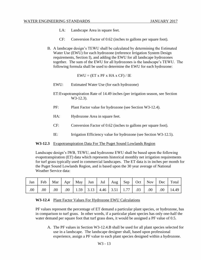
B. A landscape design’s TEWU shall be calculated by determining the Estimated
Water Use (EWU) for each hydrozone (reference Irrigation System Design
requirements, Section I), and adding the EWU for all landscape hydrozones
together. The sum of the EWU for all hydrozones is the landscape’s TEWU. The
following formula shall be used to determine the EWU for each hydrozone:
EWU = (ET x PF x HA x CF) / IE
EWU: Estimated Water Use (for each hydrozone)
ET:Evapotranspiration Rate of 14.49 inches (per irrigation season, see Section
W3-12.3).
PF: Plant Factor value for hydrozone (see Section W3-12.4).
HA: Hydrozone Area in square feet.
CF: Conversion Factor of 0.62 (inches to gallons per square foot).
IE: Irrigation Efficiency value for hydrozone (see Section W3-12.5).
W3-12.3 Evapotranspiration Data For The Puget Sound Lowlands Region
Landscape design’s IWB, TEWU, and hydrozone EWU shall be based upon the following
evapotranspiration (ET) data which represents historical monthly net irrigation requirements
for turf grass typically used in commercial landscapes. The ET data is in inches per month for
the Puget Sound Lowlands Region, and is based upon the 30 year average of National
Weather Service data:
Jan
Feb
Mar
Apr
May
Jun
Jul
Aug
Sep
Oct
Nov
Dec
Total
.00
.00
.00
.00
1.59
3.13
4.46
3.51
1.77
.03
.00
.00
14.49
W3-12.4 Plant Factor Values For Hydrozone EWU Calculations
PF values represent the percentage of ET demand a particular plant species, or hydrozone, has
in comparison to turf grass. In other words, if a particular plant species has only one-half the
water demand per square foot that turf grass does, it would be assigned a PF value of 0.5.
A. The PF values in Section W3-12.4.B shall be used for all plant species selected for
use in a landscape. The landscape designer shall, based upon professional
experience, assign a PF value to each plant species designed within a hydrozone.
WATER ENGINEERING STANDARDS JANUARY 2017
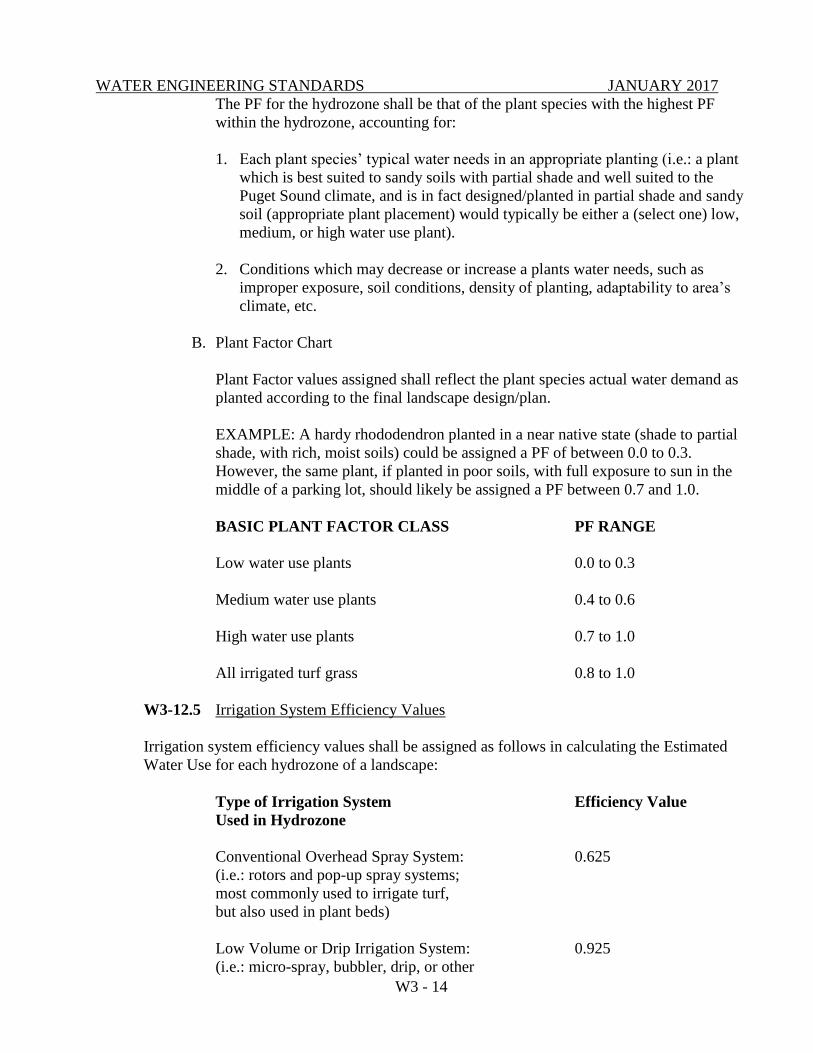
W3 - 14
The PF for the hydrozone shall be that of the plant species with the highest PF
within the hydrozone, accounting for:
1. Each plant species’ typical water needs in an appropriate planting (i.e.: a plant
which is best suited to sandy soils with partial shade and well suited to the
Puget Sound climate, and is in fact designed/planted in partial shade and sandy
soil (appropriate plant placement) would typically be either a (select one) low,
medium, or high water use plant).
2. Conditions which may decrease or increase a plants water needs, such as
improper exposure, soil conditions, density of planting, adaptability to area’s
climate, etc.
B. Plant Factor Chart
Plant Factor values assigned shall reflect the plant species actual water demand as
planted according to the final landscape design/plan.
EXAMPLE: A hardy rhododendron planted in a near native state (shade to partial
shade, with rich, moist soils) could be assigned a PF of between 0.0 to 0.3.
However, the same plant, if planted in poor soils, with full exposure to sun in the
middle of a parking lot, should likely be assigned a PF between 0.7 and 1.0.
BASIC PLANT FACTOR CLASS PF RANGE
Low water use plants 0.0 to 0.3
Medium water use plants 0.4 to 0.6
High water use plants 0.7 to 1.0
All irrigated turf grass 0.8 to 1.0
W3-12.5 Irrigation System Efficiency Values
Irrigation system efficiency values shall be assigned as follows in calculating the Estimated
Water Use for each hydrozone of a landscape:
Type of Irrigation System Efficiency Value
Used in Hydrozone
Conventional Overhead Spray System: 0.625
(i.e.: rotors and pop-up spray systems;
most commonly used to irrigate turf,
but also used in plant beds)
Low Volume or Drip Irrigation System: 0.925
(i.e.: micro-spray, bubbler, drip, or other
WATER ENGINEERING STANDARDS JANUARY 2017
W3 - 15
low volume systems which apply water
below the ground surface, or directly to
the plants root zone; most commonly used
in plant beds)
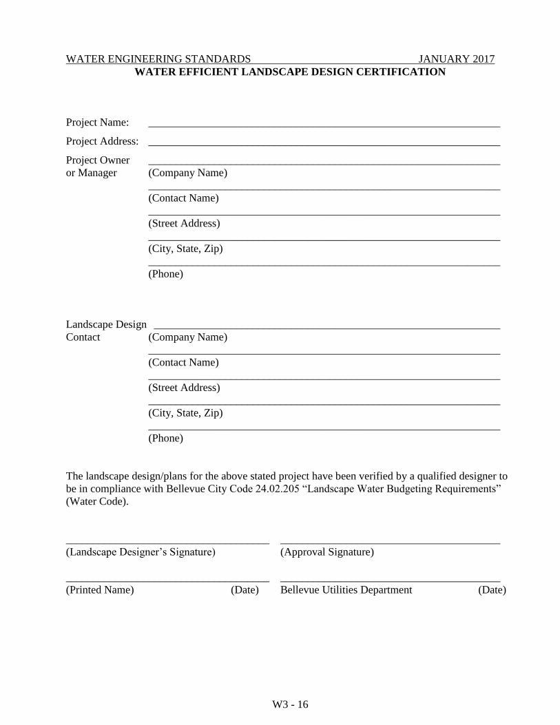
W3-12.6 Landscape Water Budgeting Certification & Forms
The “Water Efficient Landscape Design Certification”, “Irrigation Water Budget Form”, and
“Total Estimated Water Use Form” on the following pages shall be used in calculating and
reporting the landscape’s IWB, TEWU, and EWU, and to certify that the landscape has been
designed in compliance with the requirements of Bellevue City Code 24.02.205 and these
Engineering Standards.
WATER ENGINEERING STANDARDS JANUARY 2017
W3 - 16
WATER EFFICIENT LANDSCAPE DESIGN CERTIFICATION
Project Name: ________________________________________________________________
Project Address: ________________________________________________________________
Project Owner ________________________________________________________________
or Manager (Company Name)
________________________________________________________________
(Contact Name)
________________________________________________________________
(Street Address)
________________________________________________________________
(City, State, Zip)
________________________________________________________________
(Phone)
Landscape Design _______________________________________________________________
Contact (Company Name)
________________________________________________________________
(Contact Name)
________________________________________________________________
(Street Address)
________________________________________________________________
(City, State, Zip)
________________________________________________________________
(Phone)
The landscape design/plans for the above stated project have been verified by a qualified designer to
be in compliance with Bellevue City Code 24.02.205 “Landscape Water Budgeting Requirements”
(Water Code).
_____________________________________ ________________________________________
(Landscape Designer’s Signature) (Approval Signature)
_____________________________________ ________________________________________
(Printed Name) (Date) Bellevue Utilities Department (Date)
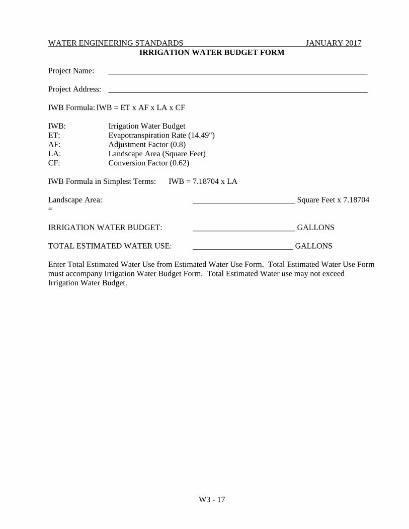
WATER ENGINEERING STANDARDS JANUARY 2017
W3 - 17
IRRIGATION WATER BUDGET FORM
Project Name:
Project Address:
IWB Formula: IWB = ET x AF x LA x CF
IWB: Irrigation Water Budget
ET: Evapotranspiration Rate (14.49")
AF: Adjustment Factor (0.8)
LA: Landscape Area (Square Feet)
CF: Conversion Factor (0.62)
IWB Formula in Simplest Terms: IWB = 7.18704 x LA
Landscape Area: Square Feet x 7.18704
=
IRRIGATION WATER BUDGET: GALLONS
TOTAL ESTIMATED WATER USE: GALLONS
Enter Total Estimated Water Use from Estimated Water Use Form. Total Estimated Water Use Form
must accompany Irrigation Water Budget Form. Total Estimated Water use may not exceed
Irrigation Water Budget.
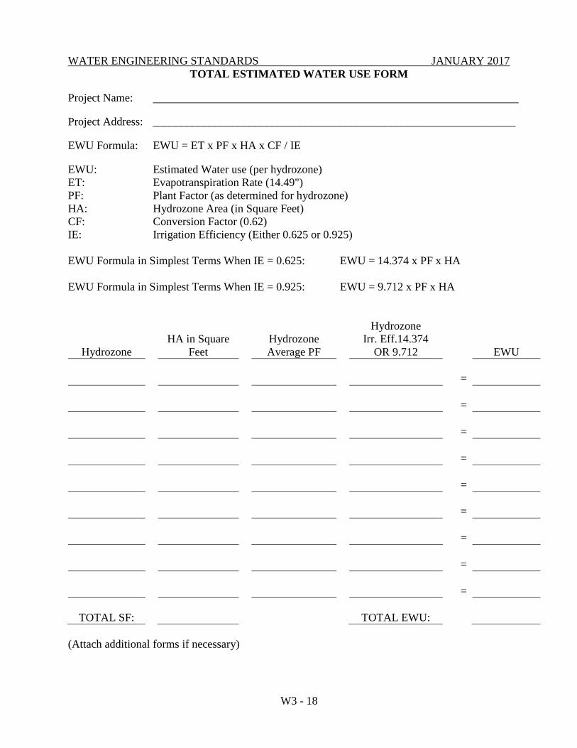
WATER ENGINEERING STANDARDS JANUARY 2017
W3 - 18
TOTAL ESTIMATED WATER USE FORM
Project Name:
Project Address: ________________________________________________________________
EWU Formula: EWU = ET x PF x HA x CF / IE
EWU: Estimated Water use (per hydrozone)
ET: Evapotranspiration Rate (14.49")
PF: Plant Factor (as determined for hydrozone)
HA: Hydrozone Area (in Square Feet)
CF: Conversion Factor (0.62)
IE: Irrigation Efficiency (Either 0.625 or 0.925)
EWU Formula in Simplest Terms When IE = 0.625: EWU = 14.374 x PF x HA
EWU Formula in Simplest Terms When IE = 0.925: EWU = 9.712 x PF x HA
Hydrozone
HA in Square
Feet
Hydrozone
Average PF
Hydrozone
Irr. Eff.14.374
OR 9.712
EWU
=
=
=
=
=
=
=
=
=
TOTAL SF:
TOTAL EWU:
(Attach additional forms if necessary)
WATER ENGINEERING STANDARDS JANUARY 2017
W3 - 19
W3-13 IRRIGATION SYSTEM DESIGN AND PERFORMANCE REQUIREMENTS
The requirements of this section shall apply to all proposed new or re-developed irrigation systems
that will be connected to the public water system, except that the requirements do not apply to the
following:
A. Single family residences; provided, that community area landscaping installed by the
developer is not exempt.
B. Any project with a total landscaped area of less than 500 square feet. If a project is
phased, the total landscape area includes all phases.
W3-13.1 General Irrigation System Design Requirements Information
A. Irrigation systems shall be designed and constructed in such a manner that separate
hydrozones within the landscape can be irrigated according to the individual
watering needs of the hydrozone. Hydrozones are groupings of plant species used
in the landscape which have similar irrigation watering needs (reference
“Landscape Water Budgeting Requirements” Section W3-12.2.B and W3-12.4.A
& B). Hydrozones of turf grass shall always be irrigated separately from other
landscape hydrozones.
B. Irrigation systems shall be designed and constructed in such a manner that a
minimum average distribution uniformity of 0.625 is achieved.
C. Copies of the “Water Efficient Irrigation System Design Certification”, Irrigation
Water Budget Form, and Total Estimated Water Use Form must be submitted to,
and approved by, the Utility prior to construction of the irrigation system.
D. An “Irrigation System Certification”, must be submitted to, and approved by the
Utility prior to Utility final acceptance of the project.
E. Location Restrictions:
1. Only low volume irrigation systems may be installed in landscape
strips less than five feet wide or in any parking lot landscape.
2. Irrigation systems shall not be installed in turf strips less than five feet
wide; in areas of turf where slopes exceed 3:1; in landscape berms
exceeding a slope of 1:1; or in turf areas in right-of-way medians, curb
strips or parking lots, with the exception that in right-of-way medians
and curb strips, up to five percent of the landscape may be irrigated turf
so long as all other requirements are met and the turf provides a
functional use for pedestrians.
W3-13.2 Irrigation System Design, Operation & Performance Requirements
A. Irrigation systems shall be designed with provisions for winterization by providing
WATER ENGINEERING STANDARDS JANUARY 2017
W3 - 20
either:
1. Manual drains (automatic valves are not permitted) at all low points, or
2. Means to blow out irrigation system pipes with pressurized air.
B. Irrigation systems shall be designed to avoid runoff, low-head drainage, overspray,
or other similar conditions where irrigation water flows onto adjacent property,
non-irrigated areas, or impervious surfaces by:
1. Considering soil type infiltration rates.
2. Using proper irrigation equipment and schedules, including such
features as repeat cycles and matched application and infiltration rates,
and
3. Considering special problems posed by irrigation on slopes, in median
strips, and in narrow hydrozones.
C. Irrigation system shall be designed to include an automatic rain shut-off device.
D. Irrigation system designs shall include a written irrigation system management
plan which includes:
1. An irrigation system operating schedule based upon the Evapotranspiration
Demand Curve, the Estimated Water use for each hydrozone, and the Total
Estimate Water Use for the landscape (reference “Landscape Water
Budgeting” Section W3-12.3 and W3-12.4.A & B.) And which details:
a. For each hydrozone (station) the run time in minutes per cycle and
cycles per week for each week of the irrigation season (May 1st
through October 31st)
b. The total weekly and annual amount of water to be applied by each
hydrozone, and the total landscape, in gallons and in hundreds of cubic
feet (CCF) (748 gallons = 1 CCF);
2. Additional operating criteria such as avoiding irrigation during times of high
winds, when raining, and/or in the middle of the day.
3. Regular maintenance activities necessary to:
a. Prevent, detect and repair irrigation system damage, excess wear, and
leakage.
b. Maintain a minimum average distribution uniformity of 0.625.
c. Activate the irrigation system for use in the spring.
WATER ENGINEERING STANDARDS JANUARY 2017
W3 - 21
d. Deactivate and winterize the irrigation system in the fall.
4. Specifications for all irrigation system components originally used, and
recommended for use when making repairs to, or replacing parts of the
irrigation system to maintain.
a. A minimum average uniform irrigation efficiency of 0.625.
b. Good overall operational performance of the irrigation system.
E. Manual watering is permitted provided it meets the intent of the irrigation system
requirements and overspray is minimized.
F. Should any of the above requirements not be met an Irrigation System Audit
Certification performed by a qualified landscape professional will be required by
the city prior to acceptance of the project.
W3-13.3 Irrigation System Design Certification
The “Irrigation System Design Certification” on the following page shall be used to certify
that the irrigation system has been designed and installed in compliance with the requirements
of Bellevue City Code 24.02.210 and the Utilities Engineering Standards.
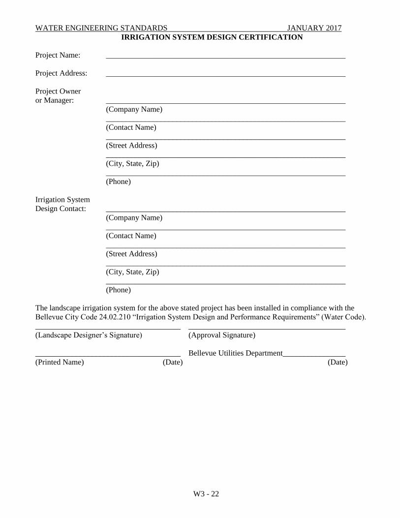
WATER ENGINEERING STANDARDS JANUARY 2017
W3 - 22
IRRIGATION SYSTEM DESIGN CERTIFICATION
Project Name: _____________________________________________________________
Project Address: _____________________________________________________________
Project Owner
or Manager: _____________________________________________________________
(Company Name)
_____________________________________________________________
(Contact Name)
_____________________________________________________________
(Street Address)
_____________________________________________________________
(City, State, Zip)
_____________________________________________________________
(Phone)
Irrigation System
Design Contact: _____________________________________________________________
(Company Name)
_____________________________________________________________
(Contact Name)
_____________________________________________________________
(Street Address)
_____________________________________________________________
(City, State, Zip)
_____________________________________________________________
(Phone)
The landscape irrigation system for the above stated project has been installed in compliance with the
Bellevue City Code 24.02.210 “Irrigation System Design and Performance Requirements” (Water Code).
_____________________________________ ________________________________________
(Landscape Designer’s Signature) (Approval Signature)
_____________________________________ Bellevue Utilities Department________________
(Printed Name) (Date) (Date)
WATER ENGINEERING STANDARDS JANUARY 2017
W3-25
END OF CHAPTER W3
WATER ENGINEERING STANDARDS JANUARY 2017
CHAPTER W4 - WATER MATERIALS
TABLE OF CONTENTS
W4-01 GENERAL .............................................................................................................. W4 - 1
W4-02 WATER PIPE ......................................................................................................... W4 - 1
W4-03 POLYETHYLENE ENCASEMENT ..................................................................... W4 - 1
W4-04 FITTINGS ............................................................................................................... W4 - 1
W4-05 GALVANIZED IRON PIPE................................................................................... W4 - 2
W4-06 COUPLINGS .......................................................................................................... W4 - 2
W4-07 ADAPTERS ............................................................................................................ W4 - 2
W4-08 BOLTS IN PIPING ................................................................................................. W4 - 2
W4-09 FLANGE GASKETS .............................................................................................. W4 - 2
W4-10 GATE VALVE ....................................................................................................... W4 - 3
W4-11 VALVE BOX.......................................................................................................... W4 - 3
W4-12 VALVE OPERATING NUT EXTENSION ........................................................... W4 - 3
W4-13 BUTTERFLY VALVE ........................................................................................... W4 - 3
W4-14 CHECK VALVE .................................................................................................... W4 - 4
W4-15 AIR AND VACUUM RELEASE VALVE ............................................................ W4 - 4
W4-16 PRESSURE REDUCING STATION .................................................................... W4 – 4
W4-17 LIDS, HATCHES AND COVERS – SLIP RESISTANCE ................................... W4 - 5
W4-18 CITY-FURNISHED INDIVIDUAL PRESSURE REDUCING
VALVE (RESIDENTIAL) ..................................................................................... W4 - 5
W4-19 CITY-FURNISHED INDIVIDUAL PRESSURE REDUCING VALVE
(MULTI-FAMILY OR COMMERCIAL) .............................................................. W4 - 5
W4-20 FIRE HYDRANT .................................................................................................. W4 – 6
W4-21 HYDRANT GUARD POSTS ................................................................................. W4 - 6
WATER ENGINEERING STANDARDS JANUARY 2017
W4-22 METER SETTER ................................................................................................... W4 - 6
W4-23 CORPORATION STOP ......................................................................................... W4 - 6
W4-24 METER BOX.......................................................................................................... W4 - 7
W4-25 COPPER SERVICE PIPE....................................................................................... W4 - 7
W4-26 NOT USED ............................................................................................................. W4 - 7
W4-27 PIPE INSULATION ............................................................................................... W4 - 8
W4-28 CONCRETE BEDDING & BLOCKING ............................................................... W4 - 8
W4-29 JOINT RESTRAINT .............................................................................................. W4 - 8
W4-30 REDUCED PRESSURE BACKFLOW ASSEMBLY ........................................... W4 - 8
W4-31 REDUCED PRESSURE DETECTOR ASSEMBLY ............................................. W4 - 8
W4-32 DOUBLE CHECK VALVE ASSEMBLY ............................................................. W4 - 8
W4-33 DOUBLE CHECK DETECTOR ASSEMBLY...................................................... W4 - 8
W4-34 BACKFLOW ASSEMBLY RESILIENT SEATED SHUT-OFF VALVES ......... W4 - 9
W4-35 BARRIER FENCE.................................................................................................. W4 - 9
W4-36 BEDDING AND BACKFILL ................................................................................ W4 - 9
W4-37 STEEL CASING ................................................................................................... W4 - 11
W4-38 CASING SPACER................................................................................................ W4 - 12
WATER ENGINEERING STANDARDS JANUARY 2017
W4 - 1
CHAPTER W4 - WATER MATERIALS
W4-01 GENERAL
All materials shall be new and undamaged. The same manufacturer of each item shall be used
throughout the work.
Where reference is made to other specifications, it shall be the latest revision at the time of
construction, except as noted on the plans or herein.
All materials not specifically referenced shall comply with applicable sections of ANSI, ASTM,
AWWA or the APWA/WSDOT Standard Specifications.
Approved manufacturers and model numbers of various materials are listed in Appendix W-4 of
these Engineering Standards. When specific manufacturers or models are listed, no substitutions will
be allowed without prior approval by the Utility.
W4-02 WATER PIPE
Water pipe shall be ductile iron pipe, minimum thickness Class 52, cement-lined unless otherwise
specified and shall conform to ANSI/AWWA C151/A21.51 or as shown on plans.
Rubber gasket pipe joints to be push-on-joint (Tyton) or mechanical joint (M.J.) in accordance with
ANSI/AWWA C111/A21.11, unless otherwise specified.
Flanged joints shall conform to ANSI B16.1, class 125 drilling pattern, rated for 250 psi working
pressure.
Standard thickness cement lining shall be in accordance with ANSI/AWWA C104/A21.4.
The Contractor shall furnish certification from the manufacturer of the pipe and gasket being supplied
that the inspection and all of the specified tests have been made and the results thereof comply with
the requirements of the above referenced standards.
W4-03 POLYETHYLENE ENCASEMENT
Polyethylene encasement shall be eight mil tube or sheet and shall be furnished with all ductile iron
pipe unless otherwise specified. Materials shall comply with ANSI/AWWA C105/A21.5.
W4-04 FITTINGS
All water main fittings shall be ductile iron, short body, cement lined, and for pressure rating of 350
psi for mechanical joint fittings and 250 psi for flange joint fittings, unless otherwise noted. Metal
thickness and manufacturing process shall conform to applicable portions of ANSI/AWWA
C110/A21.10. Mechanical joint, ductile iron, compact fittings 24 inches and less shall be in
accordance with ANSI/AWWA C153/A21.53. Flanged fittings, cast or ductile iron, shall conform to
ANSI B16.1, class 125 drilling pattern.
WATER ENGINEERING STANDARDS JANUARY 2017
W4 - 2
Standard cement lining shall be in accordance with ANSI/AWWA C104/A21.4.
Rubber gaskets for push-on-joints (Tyton) or mechanical joint (M.J.) shall be in accordance with
ANSI/AWWA C111/A21.11.
Gasket material for flanges shall be neoprene, Buna N, chlorinated butyl, or cloth-inserted rubber.
Type of connections shall be specified as push-on joint (Tyton), mechanical joint (M.J.), plain end
(P.E.), flanged (FL), and threaded.
W4-05 GALVANIZED IRON PIPE
Where galvanized iron pipe is specified, the pipe shall be Schedule 80, steel pipe per Standard
Specification for black and hot-dipped, zinc-coated (galvanized) welded and seamless steel pipe for
ordinary uses (ASTM A-120). Fittings shall be screwed malleable iron galvanized per ANSI B16.3.
Galvanized pipe shall be used only for dry pipe in pressure relief and air valve assemblies.
W4-06 COUPLINGS
Flexible coupling and transition coupling cast components shall be ductile iron. Center rings and end
rings shall be ductile iron in accordance with ASTM 536-80, Grade 65-45-12.
Gasket material shall be virgin SBR in accordance with ASTM D2000 MBA 710.
Bolts shall be high strength, low alloy steel track-head bolts with national course rolled thread and
heavy hex nuts. Steel shall meet ANSI/AWWA C111/A21.11 composition specifications.
W4-07 ADAPTERS
All flange by mechanical joint (FL x MJ) adapters shall be ductile iron.
W4-08 BOLTS IN PIPING
Bolts shall be malleable iron, Cor-ten, or stainless steel.
Bolts and nuts for flanged pipe and fittings shall conform in size and length with ANSI/AWWA
C115/A21.15. T-bolts shall be malleable iron or Cor-ten in accordance with ANSI/AWWA
C111/A21.11. Stainless steel bolts shall meet the requirements of ASTM A193 Grade B8M.
Shackle rods shall be stainless steel all thread 316SS.
Stainless steel nuts, bolts and washers shall be type 316SS.
W4-09 FLANGE GASKETS
Gasket Material shall be neoprene, Buna N, chlorinated butyl, or cloth inserted rubber.
WATER ENGINEERING STANDARDS JANUARY 2017
W4 - 3
W4-10 GATE VALVE
The minimum requirements for all gate valves shall, in design, material, workmanship, have
approximately 45 turns full open to full closed, and conform to the following Standards:
2” to 12” Cast Iron: AWWA C-509
4” to 12” Ductile Iron: AWWA C-515
14” to 24” Ductile Iron: AWWA C-515
30” to 36” Ductile Iron: AWWA C-515
42” to 48” Ductile Iron: AWWA C-515
Buried gate valves shall be iron body, bronze mounted, resilient seat, and non-rising stem, suitable
for installation with the type and class of pipe being installed. Ends to be as specified. Operating
stems shall be equipped with standard two (2) inch operation nut, and O-ring stem seals. Valves not
buried shall be as specified. Insertion valves shall be mounted on concrete support block.
W4-11 VALVE BOX
Valve Box shall be cast iron, two-piece, 8" or 18" slip type top section with flange located within 3"
of top, with 24" bottom section (and extension, if required), equal to RICH - Seattle Type. Valve box
lid shall be cast iron, 3 " deep, with recessed lifting handle, and the word “WATER” or “WW” cast
into it.
Valve box paving risers shall be cast iron suitable for H-20 traffic loading. The riser shall have four
lugs or a flange around the perimeter, and be sized to fit into a RICH - Seattle Type valve box top.
Valve box adjusting sleeves (for use in unimproved areas) shall be cast iron, 12" long.
All castings shall be coated with asphaltic varnish.
W4-12 VALVE OPERATING NUT EXTENSION
Use where valves are installed more than 3' below finished grade. Extensions are to be a minimum of
1' with only one extension per valve. See Standard Detail.
W4-13 BUTTERFLY VALVE
Butterfly valves shall conform to ANSI/AWWA C504, Class 150B, and be approximately 45 turns
full open to full closed. Valves in chambers shall have a manual hand wheel operation. Buried
valves shall have a stem extension with AWWA 2-inch operating nut and suitable valve box.
W4-14 CHECK VALVE
Check valves shall be for 150 psi working pressure, unless otherwise specified. Valve shall have
adjustable tension lever and spring to provide non-slamming action under all conditions unless
otherwise specified.
WATER ENGINEERING STANDARDS JANUARY 2017
W4 - 4
W4-15 AIR AND VACUUM RELEASE VALVE WITH VACUUM CHECK VALVE
Combination Air Valves shall be of the single housing style that combines the operating features of
both an Air/Vacuum and Air Release Valve.
The Air/Vacuum portion shall automatically exhaust air during the filling of the pipeline and prevent
air to re-enter the pipeline when the internal pressure of the pipeline approaches a negative value due
to column separation, draining of the pipeline, power outage, pipeline break, etc.
The Air Release portion shall automatically release small pockets of air from the pipeline while the
pipeline is in operation and under pressure, and during filling of the pipeline.
The Combination Air Valve shall have minimum 1" NPT inlet and outlet connections and be able to
withstand a working pressure of 300 PSI.
Vacuum check valve shall be installed on top of the air vent on the Air/Vac or Air/Release valve to
prevent air from re-entering the water main under any vacuum conditions.
The valve body and cover shall be cast iron with stainless steel float.
W4-16 PRESSURE REDUCING STATION
Unless otherwise shown on the construction plans, a standard pressure reducing station shall have a
6" pressure reducing valve with flanged ends and a bypass with a 2" pressure reducing valve with
threaded ends. Pressure reducing valves shall have opening/closing speed controls, epoxy coated
body, and valve position indicator. Pressure reducing valves and pressure relief valves shall be
equipped with stainless steel trim (seat, stem, and cover bearing). Pilot controls shall be on the side
of the pressure reducing valve facing vault interior. Each pressure reducing valve shall include two
3/8" test cocks located on the opposite side of valve body from the pilot controls (one at inlet and one
at outlet end of valve).
Strainers shall be installed on the inlet side of each pressure reducing valve with bronze ball valve
sized to correspond with the strainer blow-off outlet size. A 2" pressure relief valve with threaded
ends shall be installed on the discharge side of the 2" pressure reducing valve line and vented to
atmosphere as shown on the plans.
The pressure reducing valve shall maintain a constant downstream pressure regardless of varying
inlet pressure. The valve shall be a hydraulically operated diaphragm-actuated, globe valve. The
pilot control shall be a direct-acting, adjustable, spring loaded, normally open, diaphragm valve,
designed to permit flow when controlled pressure is less than the spring setting. The control system
shall include a fixed orifice.
The pressure relief valve shall maintain constant upstream pressure by by-passing or relieving excess
pressure, and shall maintain close pressure limits without causing surges. The main valve shall be
hydraulically operated, diaphragm-actuated, globe valve. The pilot control shall be a direct acting,
adjustable, spring loaded, diaphragm valve, designed to permit flow when controlling pressure
exceeds spring setting. The pilot control system shall operate such that as excess line pressure is
WATER ENGINEERING STANDARDS JANUARY 2017
W4 - 5
dissipated the main valve shall gradually close to a positive, drip-tight seating.
All diaphragm-actuated valves shall contain a resilient, synthetic rubber disc, having a rectangular
cross-section, contained on three and one-half sides by a disc retainer and forming a tight seal against
a single removable seat insert. The diaphragm assembly containing a valve stem shall be fully guided
at both ends by a bearing in the valve cover and an integral bearing in the valve seat. This diaphragm
assembly shall be the only moving part and shall form a sealed chamber in the upper portion of the
valve, separating operating pressure from line pressure. The diaphragm shall consist of nylon fabric
bonded with synthetic rubber and shall not be used as a seating surface. Packing glands and/or
stuffing boxes are not permitted and there shall be no pistons operating the valve or pilot controls.
All necessary repairs shall be possible without removing the valve from the line.
Strainers 2 inches and smaller shall be iron bodied "Y" type equal in size to corresponding pressure
reducing valve. Strainers 3 inches and larger shall be Cla-Val X43H “H” style strainers. Strainer
shall feature bolted cover machined to hold screen securely in place and tapped F.I.P.T. for blow-off
outlet. Screens 2 inches and smaller shall be constructed from perforated stainless steel. . Main-line
strainer shall have flanged-ends and bypass strainer shall have threaded ends.
The vault shall be equal to Oldcastle Precast model 777-LA with cover as specified in the Standard
Detail. Vault exterior shall be coated with a single component, moisture curing urethane with
micaceous iron oxide applied at 5 to 7 micron dry film thickness per coat, two coats minimum,
Sherwin-Williams Corothane 1-Coal Tar, or equal. Vault interior shall not be coated.
W4-17 LIDS, HATCHES AND COVERS – SLIP RESISTANCE
Metal lids, hatches and access covers shall be constructed with a non-slip treatment having a
coefficient of friction between 0.6 and 1.0 wet, as determined by ASTM C1028-89. Lids, hatches
and access covers located on slopes of 4% or greater shall have a coefficient of friction between 0.8
and 1.0 wet, as determined by ASTM C1028-89. Prior to installation, the Contractor shall supply the
Engineer with a shop drawing of the appurtenance, specifying a coefficient of friction meeting or
exceeding the above requirement.
W4-18 CITY-FURNISHED INDIVIDUAL PRESSURE REDUCING VALVE
(RESIDENTIAL)
Individual pressure reducing valve shall be direct-acting piston type with integral strainer and bypass.
Valve body shall be bronze with threaded outlet end and integral union on inlet end. Valve shall be
line-sized with spring range from 25 to 75 psi.
All other appurtenances shall be as shown in the Standard Detail.
W4-19 CITY-FURNISHED INDIVIDUAL PRESSURE REDUCING VALVE (MULTI-
FAMILY OR COMMERCIAL)
Individual pressure reducing valve shall be equipped with a pressure relief valve at the discharge
side, unless otherwise shown in the plans. Unless otherwise directed by the engineer, the contractor
shall construct the pressure reducing valve assembly in accordance with the Standard Detail.
Individual pressure reducing valve shall be direct-acting piston type with integral strainer and bypass.
WATER ENGINEERING STANDARDS JANUARY 2017
W4 - 6
Valve body shall be bronze with threaded outlet end and integral union on inlet end. Valve shall be
line-sized with spring range from 25 to 75 psi.
The pressure relief valve shall be a 3/4" hydraulically or pneumatically operated, diaphragm actuated
globe valve. It shall be direct-acting, adjustable, spring loaded and designed to permit flow when
pressure exceeds the spring setting. Spring range shall be from 20 to 200 psi.
All other appurtenances shall be as shown in the Standard Details.
W4-20 FIRE HYDRANT
Fire Hydrants shall have a minimum valve opening of five and one-quarter (5-1/4") inch "O" ring
stem seal, two - two and one half (2 - 2 1/2") inch N.S.T. hose nozzle connections, and one-four (1-
4") inch pumper connection with City of Seattle standard threads. The shoe connection, foot valve
connection, and all joints between shall be six-inch mechanical joints with lugs. The operating and
port cap nuts are one and one-quarter (1-1/4") inch pentagonal. Hydrants shall be as shown in the
approved materials list, with no exceptions unless approved by the Engineer. All hydrants shall be of
the "Traffic Model" type with approved break-away features and brass to brass sub-seat. Shackle
rods are not permitted on hydrants.
The portion of the public fire hydrant that is above ground shall be painted with two (2) coats of
Rust-Oleum, Krylon, or Sherwin-Williams Safety Yellow paint.
The portion of the private fire hydrant that is above ground shall be painted with two coats of Rust-
Oleum, Krylon, or Sherwin-Williams Red paint as set forth by the City of Bellevue Fire Department.
W4-21 HYDRANT GUARD POSTS
Hydrant guard posts shall be 6" diameter concrete filled ductile iron pipe class 52, 6 feet long. Posts
shall be painted with two (2) coats of Rust-Oleum, Krylon, or Sherwin-Williams Safety Yellow paint.
W4-22 METER SETTER
Meter setters shall have dual purpose couplings, unless otherwise specified, and angle meter valve
with drilled wings for padlock, twelve (12") inches high. The angle copper setter for the size meter to
be installed, see Standard Details.
1 1/2" meter setters shall have vertical inlet and outlet tees with 1" lateral bypass, flanged ball meter
valves on inlet and outlet, ball valve on bypass, and padlock wings on all valves, see Standard
Details.
2" meter setters shall have vertical inlet and outlet tees with 1" lateral bypass, flanged ball meter
valve on inlet, flanged key meter valve on outlet, ball valve on bypass, and padlock wings on all
valves, see Standard Details.
W4-23 CORPORATION STOP
Corporation stops shall be brass in accordance with AWWA Standard C800 with AWWA tapered
thread (CC) inlet by compression fitting for copper outlet, complete with coupling nut for copper
service.
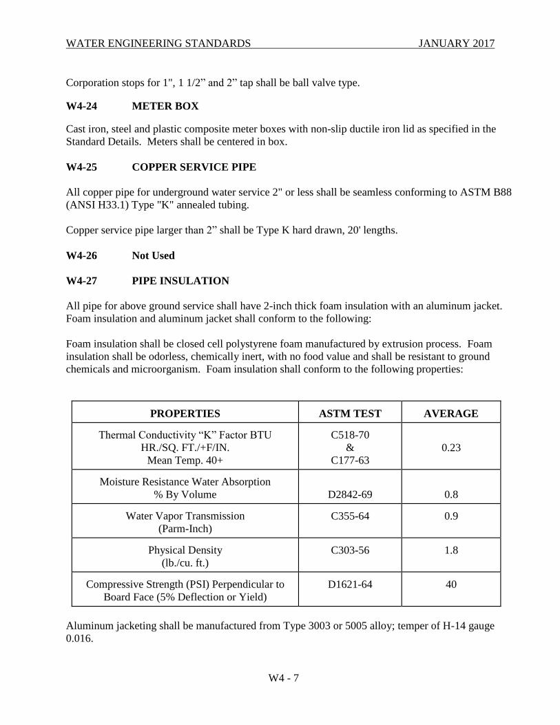
WATER ENGINEERING STANDARDS JANUARY 2017
W4 - 7
Corporation stops for 1", 1 1/2” and 2” tap shall be ball valve type.
W4-24 METER BOX
Cast iron, steel and plastic composite meter boxes with non-slip ductile iron lid as specified in the
Standard Details. Meters shall be centered in box.
W4-25 COPPER SERVICE PIPE
All copper pipe for underground water service 2" or less shall be seamless conforming to ASTM B88
(ANSI H33.1) Type "K" annealed tubing.
Copper service pipe larger than 2” shall be Type K hard drawn, 20' lengths.
W4-26 Not Used
W4-27 PIPE INSULATION
All pipe for above ground service shall have 2-inch thick foam insulation with an aluminum jacket.
Foam insulation and aluminum jacket shall conform to the following:
Foam insulation shall be closed cell polystyrene foam manufactured by extrusion process. Foam
insulation shall be odorless, chemically inert, with no food value and shall be resistant to ground
chemicals and microorganism. Foam insulation shall conform to the following properties:
PROPERTIES
ASTM TEST
AVERAGE
Thermal Conductivity “K” Factor BTU
HR./SQ. FT./+F/IN.
Mean Temp. 40+
C518-70
&
C177-63
0.23
Moisture Resistance Water Absorption
% By Volume
D2842-69
0.8 Water Vapor Transmission
(Parm-Inch)
C355-64
0.9
Physical Density
(lb./cu. ft.)
C303-56
1.8
Compressive Strength (PSI) Perpendicular to
Board Face (5% Deflection or Yield)
D1621-64
40
Aluminum jacketing shall be manufactured from Type 3003 or 5005 alloy; temper of H-14 gauge
0.016.
WATER ENGINEERING STANDARDS JANUARY 2017
W4 - 8
W4-28 CONCRETE BEDDING & BLOCKING
Bedding, blocking, encasement, or slope anchor concrete shall be mixed from materials acceptable
to the Engineer and shall have a 30-day compressive strength of not less than 2,500 psi. The mix
shall contain five (5) sacks of cement per cubic yard and shall be of such consistency that the slump
is between 1 inch and 5 inches. All concrete shall be mechanically mixed. Blocks shall be left open
for inspection.
W4-29 JOINT RESTRAINT
Joint restraint methods shall be as per the Approved Materials list. Where shackle restraint is used,
all shackle rods shall be stainless steel (All Thread 316SS), along with 316SS stainless steel
hardware. Stainless steel shackle restraints do not require painting.
W4-30 REDUCED PRESSURE BACKFLOW ASSEMBLY
All Reduced Pressure Backflow Assemblies shall be as listed on the most current copy of
"Backflow Prevention Assemblies Approved for Installation in Washington State", published by
Washington State Department of Health (D.O.H.). The assembly shall include a tightly closing
resilient seated shut-off valve on each end of the body and each assembly shall be fitted with four
properly located resilient seated test cocks.
All other appurtenances shall be as shown in the Standard Detail.
W4-31 REDUCED PRESSURE DETECTOR ASSEMBLY
This assembly shall include a line-sized D.O.H. approved (listed on the most current copy of
"Backflow Prevention Assemblies Approved for Installation in Washington State" published by
Washington State D.O.H.) Reduced Pressure Backflow Assembly with a parallel 3/4" meter and
3/4" D.O.H. approved Reduced Pressure Backflow Assembly. Each assembly shall include a
tightly closing resilient seated shut-off valve on each end of the body and each assembly shall be
fitted with four properly located resilient seated test cocks.
All other appurtenances shall be as shown in the Standard Detail.
W4-32 DOUBLE CHECK VALVE ASSEMBLY
All Double Check Valve Assemblies shall be as listed on the most current copy of "Backflow
Prevention Assemblies Approved for Installation in Washington State" published by Washington
State D.O.H. The assembly shall include a tightly closing resilient seated shut-off valve on each
end of the body and each assembly shall be fitted with four properly located resilient seated test
cocks.
All other appurtenances shall be as shown in the Standard Detail.
W4-33 DOUBLE CHECK DETECTOR ASSEMBLY
This assembly shall include a line sized D.O.H. approved (listed on the most current copy of
WATER ENGINEERING STANDARDS JANUARY 2017
W4 - 9
"Backflow Prevention Assemblies Approved for Installation in Washington State" published by
Washington State D.O.H.) Double Check Valve Assembly with a parallel 3/4" meter and 3/4"
D.O.H. approved double check Valve Assembly. Each assembly shall include a tightly closing
resilient seated shut-off valve on each end of the body and each assembly shall be fitted with four
properly located resilient seated test-cocks.
All other appurtenances shall be as shown in the Standard Detail.
W4-34 BACKFLOW ASSEMBLY RESILIENT SEATED SHUT-OFF VALVES
Each valve shall be marked with model number with designation of resilient seat; such as "RS" or
"R", which must be cast, molded, or affixed onto the body or bonnet of the valve. All ferrous-
bodied valves shall be coated with a minimum of 4 mils of epoxy or equivalent polymerized
coating. 2" and smaller R.P.B.A.s and D.C.V.A.s shall use ball valves, and all 2-1/2" and larger
R.P.B.A.s and D.C.V.A.s shall use resilient seated gate valves for domestic supply and resilient
seated O.S. and Y. valves for firelines.
The minimum requirements for all resilient seated gate valves shall, in design, material and
workmanship, conform to the standards of AWWA C509.
W4-35 BARRIER FENCE
Barrier Mesh shall be manufactured from Low Density Polyethylene, stabilized against UV
degradation, and with a special selection of pigments to ensure optimum visual performance under
harsh weather conditions. Barrier Mesh shall be corrosion-free and resistant to salt water and most
chemicals.
Barrier Mesh shall present a visual target area of approximately 0.5 square meter per square meter
of mesh.
W4-36 BEDDING AND BACKFILL
W4-36.1 Pipe Bedding Materials
For Reinforced Concrete Pipe (RCP), Corrugated Metal Pipe (CMP - which includes steel
and aluminum), and Ductile Iron Pipe (DIP), bedding material shall be in accordance with
Section 9-03.12(3) Gravel Backfill for Pipe Zone Bedding of the Standard Specifications.
For convenience, crushed rock bedding conforming to crushed surfacing top course material
of Section 9-03.9(3) Crushed Surfacing of the Standard Specifications may also be used as
bedding material for pipe.
In unpaved areas, the Contractor may request to use excavated material used as pipe bedding
where it has been determined by the Engineer as suitable meeting the requirements of
Section 9-03.12(3) Gravel Backfill for Pipe Zone Bedding of the Standard Specifications,
and proper compaction levels can be achieved.
For Polyvinyl Chloride (PVC) pipe, Corrugated Polyethylene (CPE) pipe, and other
WATER ENGINEERING STANDARDS JANUARY 2017
W4 - 10
thermoplastic pipe, bedding material shall be imported material conforming to crushed
surfacing top course material of Section 9-03.9(3) Crushed Surfacing of the Standard
Specifications.
For ductile iron water main pipe, the Contractor may request to use excavated material as
pipe bedding where it has been determined by the Engineer as suitable material meeting the
requirements of Section 9-03.12(3) Gravel Backfill for Pipe Zone Bedding of the Standard
Specifications and proper compaction levels can be achieved.
W4-36.2 Trench Backfill Materials
For transverse trenches (perpendicular to the roadway centerline) in paved areas, crushed
rock backfill conforming to Section 9-03.9(3) Crushed Surfacing of the Standard
Specifications shall be used as trench backfill for pipe.
For longitudinal trenches (trenches parallel to the centerline of the roadway) in paved areas,
backfill material (4 feet and deeper below finished grade) shall conform to Section
9-03.14(1) Gravel Borrow of the Standard Specifications. The Contractor may request to
use excavated material as trench backfill and must demonstrate to the Engineer that the
suitable excavated material conforms to Section 9-03.14(1) Gravel Borrow of the Standard
Specifications and proper compaction levels can be achieved. Admixtures and/or additives
may not be used to modify the moisture content in order to meet compaction specifications.
The top 4 feet of longitudinal trenches shall be backfilled with crushed rock conforming to
Section 9-03.9(3) Crushed Surfacing of the Standard Specifications.
In unpaved areas, trench backfill material shall conform to Section 9-03.14(1) Gravel
Borrow of the Standard Specifications. The Contractor may request to use excavated
material as trench backfill when it has been determined by the Engineer to be suitable and
conforms to Section 9-03.14(1) Gravel Borrow of the Standard Specifications and proper
compaction levels can be achieved.
4-36.3 Structure Backfill Materials
In paved areas, backfill material (4 feet and deeper below finished grade) shall conform to
Section 9-03.14(1) Gravel Borrow of the Standard Specifications. The Contractor may
request to use excavated material as trench backfill when it has been determined by the
Engineer to be suitable and conforms to Section 9-03.14(1) Gravel Borrow of the Standard
Specifications and proper compaction levels can be achieved.
The top 4 feet around structures shall be backfilled with crushed rock conforming to Section
9-03.9(3) Crushed Surfacing - Top Course of the Standard Specifications.
In unpaved areas, structure backfill material shall conform to Section 9-03.14(1) Gravel
Borrow of the Standard Specifications. The Contractor may request to use excavated
material as structure backfill when it has been determined by the Engineer to be suitable and
conforms to Section 9-03.14(1) Gravel Borrow of the Standard Specifications and proper
compaction levels can be achieved.
WATER ENGINEERING STANDARDS JANUARY 2017
W4 - 11
4-36.4 Foundation Gravel Materials
Foundation gravel for structures shall consist of one of the following aggregates as set forth
in the Standard Specifications:
Ballast 9-03.9(1)
Shoulder Ballast 9-03.9(2)
Gravel Backfill for Foundations (Class A or B) 9-03.12(1)
Foundation Material Class A and Class B 9-03.17
4-36.5 Controlled Density Fill Materials
Controlled density fill (CDF, aka flowable fill) shall be a mixture of Portland Cement,
admixture (optional), Fly Ash, aggregates and water. It shall be proportioned to provide a
slurry, non-segregating, free flowing, self-consolidating and excavatable material that will
result in a non-settling fill which has measurable unconfined compressive strength.
Materials testing shall be with unconfined compressive test cylinders. Test data may be
either laboratory trial batch test data or field test data.
Alternate mix designs may be required at the Engineer's discretion.
The unconfined compressive strength at 28 days shall be a minimum of 50 psi and a
maximum of 100 psi. Material shall be a sand/grout slurry proportioned to be
hand-excavatable after long term strength gain.
Materials shall meet the requirements of the following sections of the Standard
Specifications:
Portland Cement 9-01
Fine Aggregate for Portland Cement Concrete 9-03.1(2)
Admixture for Concrete 9-23.6
Fly Ash 9-23.9
Water 9-25
Controlled density fill shall meet the following requirements:
Controlled Density Fill
Ingredients Amount per Cu. Yd.
Portland Cement 50 lb.
Aggregates Class 1 or 2 3300 lb.
Air Entrainment Admixture Per Manufacturer’s recommendations
Fly Ash Class F 300 lb.
Water 300 lb. (maximum)
The material consistency shall be flowable (approx. slump 3-10 inches). If requested by the
Contractor, the proportions may be adjusted with the approval of the Engineer.
WATER ENGINEERING STANDARDS JANUARY 2017
W4 - 12
W4-37 STEEL CASING
Steel casing shall be black steel pipe conforming to ASTM A53. Before installation, coat casing
exterior with shop-applied anticorrosive coating conforming to AWWA C210. Minimum coating
thickness shall be 16 mils dry film thickness (DFT); however, thickness shall not exceed
manufacturer’s recommended thickness. Coating type shall be a polyamide epoxy-coal tar equal to
Tnemec Hi-Build Tneme-Tar, Series 46H-413.
Casing wall thickness shall be 0.250 inch for casings 24 inches or less in diameter and 0.375 inch
for casings over 24 inches in diameter.
Carrier pipe for water shall be Ductile Iron, Class 52.
W4-38 CASING SPACER
Casing spacer shell shall be manufactured in two pieces from heavy gauge T-304 stainless steel or
14 gauge hot rolled pickled steel joined with ribbed flanges. The shell shall be lined with a PVC
liner 0.090 inch thick with 85-90 durometer.
Carbon steel casing spacer shell and risers shall be coated with a heat fused Polyvinyl chloride
coating, or hot-dip galvanized.
Polyvinyl Chloride Coating Specifications:
Durometer - Shore A2 (10 Sec.) (ASTM D-1706-61T) - 80
Maximum operating temperature (constant) - 150° (65°C)
Electrical properties (ASTM D-149-61)
(short time .010") - 1380 V/Mil
Resistance:
Salt spray (ASTM B-117) - Excellent
Acids - Good
Alkalies - Good
All nuts and bolts shall be 18-8 stainless steel.
Runners shall be supported by risers made from heavy gauge T-304 stainless steel or 12 gauge hot
rolled pickled steel. Runners shall be ultra-high molecular weight polymer with high resistance to
abrasion and sliding wear.
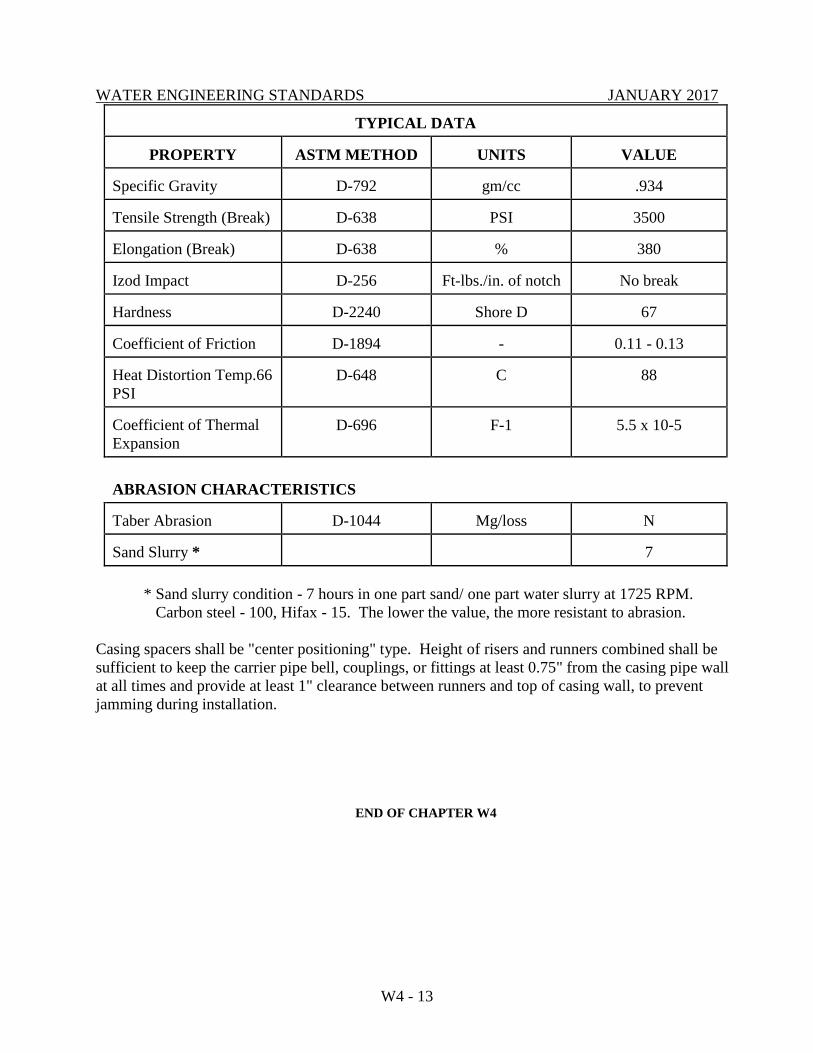
WATER ENGINEERING STANDARDS JANUARY 2017
W4 - 13
TYPICAL DATA
PROPERTY
ASTM METHOD
UNITS
VALUE
Specific Gravity
D-792
gm/cc
.934
Tensile Strength (Break)
D-638
PSI
3500
Elongation (Break)
D-638
%
380
Izod Impact
D-256
Ft-lbs./in. of notch
No break
Hardness
D-2240
Shore D
67
Coefficient of Friction
D-1894
-
0.11 - 0.13
Heat Distortion Temp.66
PSI
D-648
C
88
Coefficient of Thermal
Expansion
D-696
F-1
5.5 x 10⁻⁵
ABRASION CHARACTERISTICS
Taber Abrasion
D-1044
Mg/loss
N
Sand Slurry *
7
* Sand slurry condition - 7 hours in one part sand/ one part water slurry at 1725 RPM.
Carbon steel - 100, Hifax - 15. The lower the value, the more resistant to abrasion.
Casing spacers shall be "center positioning" type. Height of risers and runners combined shall be
sufficient to keep the carrier pipe bell, couplings, or fittings at least 0.75" from the casing pipe wall
at all times and provide at least 1" clearance between runners and top of casing wall, to prevent
jamming during installation.
END OF CHAPTER W4
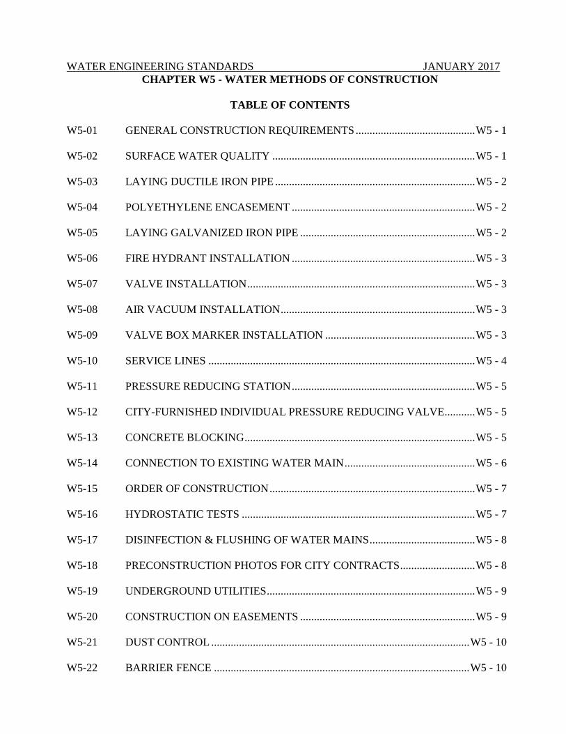
WATER ENGINEERING STANDARDS JANUARY 2017
CHAPTER W5 - WATER METHODS OF CONSTRUCTION
TABLE OF CONTENTS
W5-01 GENERAL CONSTRUCTION REQUIREMENTS ........................................... W5 - 1
W5-02 SURFACE WATER QUALITY ......................................................................... W5 - 1
W5-03 LAYING DUCTILE IRON PIPE ........................................................................ W5 - 2
W5-04 POLYETHYLENE ENCASEMENT .................................................................. W5 - 2
W5-05 LAYING GALVANIZED IRON PIPE ............................................................... W5 - 2
W5-06 FIRE HYDRANT INSTALLATION .................................................................. W5 - 3
W5-07 VALVE INSTALLATION .................................................................................. W5 - 3
W5-08 AIR VACUUM INSTALLATION ...................................................................... W5 - 3
W5-09 VALVE BOX MARKER INSTALLATION ...................................................... W5 - 3
W5-10 SERVICE LINES ................................................................................................ W5 - 4
W5-11 PRESSURE REDUCING STATION .................................................................. W5 - 5
W5-12 CITY-FURNISHED INDIVIDUAL PRESSURE REDUCING VALVE........... W5 - 5
W5-13 CONCRETE BLOCKING ................................................................................... W5 - 5
W5-14 CONNECTION TO EXISTING WATER MAIN ............................................... W5 - 6
W5-15 ORDER OF CONSTRUCTION .......................................................................... W5 - 7
W5-16 HYDROSTATIC TESTS .................................................................................... W5 - 7
W5-17 DISINFECTION & FLUSHING OF WATER MAINS ...................................... W5 - 8
W5-18 PRECONSTRUCTION PHOTOS FOR CITY CONTRACTS ........................... W5 - 8
W5-19 UNDERGROUND UTILITIES ........................................................................... W5 - 9
W5-20 CONSTRUCTION ON EASEMENTS ............................................................... W5 - 9
W5-21 DUST CONTROL ............................................................................................. W5 - 10
W5-22 BARRIER FENCE ............................................................................................ W5 - 10
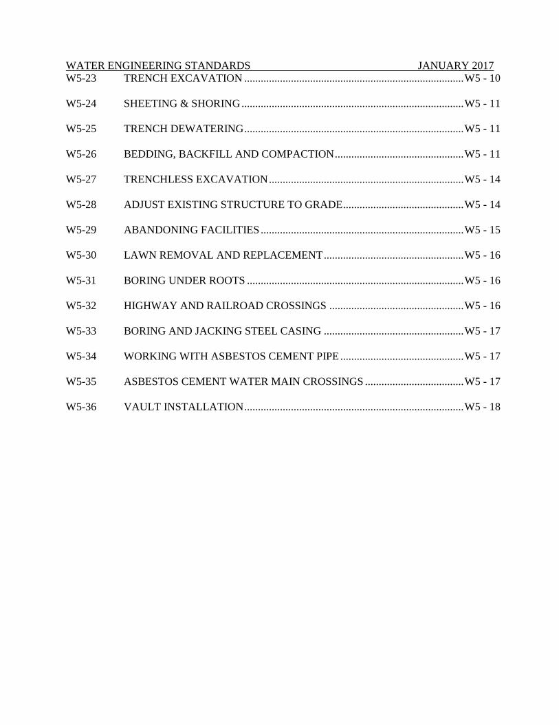
WATER ENGINEERING STANDARDS JANUARY 2017
W5-23 TRENCH EXCAVATION ................................................................................ W5 - 10
W5-24 SHEETING & SHORING ................................................................................. W5 - 11
W5-25 TRENCH DEWATERING ................................................................................ W5 - 11
W5-26 BEDDING, BACKFILL AND COMPACTION ............................................... W5 - 11
W5-27 TRENCHLESS EXCAVATION ....................................................................... W5 - 14
W5-28 ADJUST EXISTING STRUCTURE TO GRADE ............................................ W5 - 14
W5-29 ABANDONING FACILITIES .......................................................................... W5 - 15
W5-30 LAWN REMOVAL AND REPLACEMENT ................................................... W5 - 16
W5-31 BORING UNDER ROOTS ............................................................................... W5 - 16
W5-32 HIGHWAY AND RAILROAD CROSSINGS ................................................. W5 - 16
W5-33 BORING AND JACKING STEEL CASING ................................................... W5 - 17
W5-34 WORKING WITH ASBESTOS CEMENT PIPE ............................................. W5 - 17
W5-35 ASBESTOS CEMENT WATER MAIN CROSSINGS .................................... W5 - 17
W5-36 VAULT INSTALLATION ................................................................................ W5 - 18
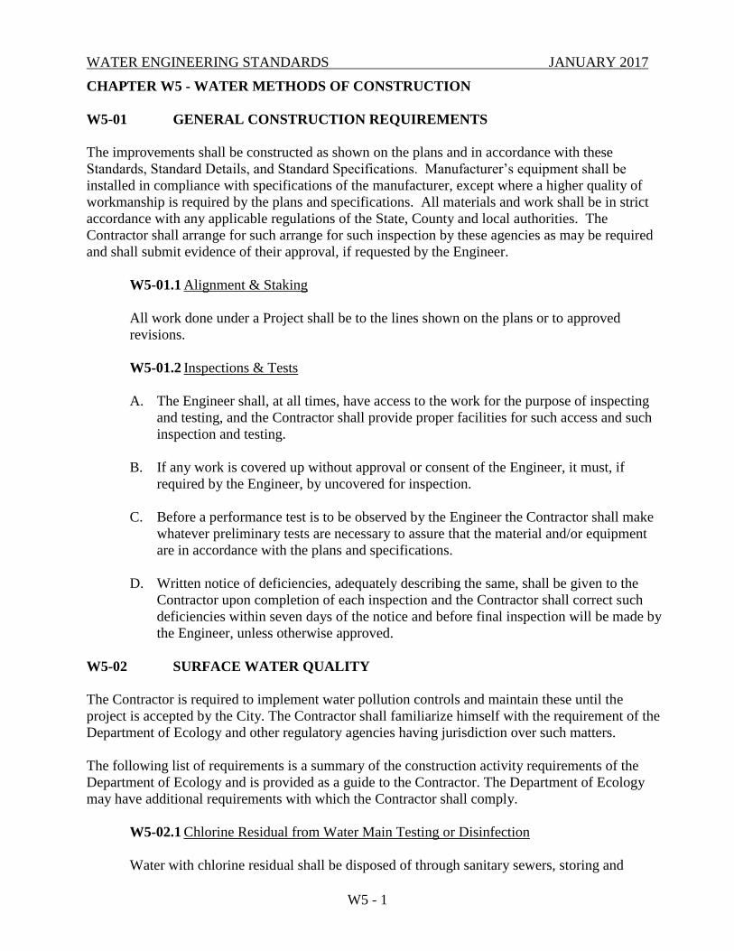
WATER ENGINEERING STANDARDS JANUARY 2017
W5 - 1
CHAPTER W5 - WATER METHODS OF CONSTRUCTION
W5-01 GENERAL CONSTRUCTION REQUIREMENTS
The improvements shall be constructed as shown on the plans and in accordance with these
Standards, Standard Details, and Standard Specifications. Manufacturer’s equipment shall be
installed in compliance with specifications of the manufacturer, except where a higher quality of
workmanship is required by the plans and specifications. All materials and work shall be in strict
accordance with any applicable regulations of the State, County and local authorities. The
Contractor shall arrange for such arrange for such inspection by these agencies as may be required
and shall submit evidence of their approval, if requested by the Engineer.
W5-01.1 Alignment & Staking
All work done under a Project shall be to the lines shown on the plans or to approved
revisions.
W5-01.2 Inspections & Tests
A. The Engineer shall, at all times, have access to the work for the purpose of inspecting
and testing, and the Contractor shall provide proper facilities for such access and such
inspection and testing.
B. If any work is covered up without approval or consent of the Engineer, it must, if
required by the Engineer, by uncovered for inspection.
C. Before a performance test is to be observed by the Engineer the Contractor shall make
whatever preliminary tests are necessary to assure that the material and/or equipment
are in accordance with the plans and specifications.
D. Written notice of deficiencies, adequately describing the same, shall be given to the
Contractor upon completion of each inspection and the Contractor shall correct such
deficiencies within seven days of the notice and before final inspection will be made by
the Engineer, unless otherwise approved.
W5-02 SURFACE WATER QUALITY
The Contractor is required to implement water pollution controls and maintain these until the
project is accepted by the City. The Contractor shall familiarize himself with the requirement of the
Department of Ecology and other regulatory agencies having jurisdiction over such matters.
The following list of requirements is a summary of the construction activity requirements of the
Department of Ecology and is provided as a guide to the Contractor. The Department of Ecology
may have additional requirements with which the Contractor shall comply.
W5-02.1 Chlorine Residual from Water Main Testing or Disinfection
Water with chlorine residual shall be disposed of through sanitary sewers, storing and
WATER ENGINEERING STANDARDS JANUARY 2017
W5 - 2
aerating or percolation into the ground. Water containing a chlorine residual shall not be
disposed of into the storm drainage system or any waterway.
W5-02.2 Oil and Chemical Storage and Handling
Storage area shall be diked. No disposal of oil products or waste on the site, including oil
filters. The Contractor shall provide a waste oil disposal tank, if needed.
W5-03 LAYING DUCTILE IRON PIPE
Work shall be accomplished in accordance with AWWA Standard C600 and the manufacturer’s
recommendation.
The bottom of the trench shall be finished to grade in such a manner that the pipe will have
bearing along the entire length of the barrel. Bolts on mechanical pipe and fittings shall be
tightened uniformly with a "Torque" wrench which measures the torque for mechanical joints
shall be as follows:
2" - 3" pipe sizes 5/8" Bolts 40 - 60 ft-lbs torque
4" - 24" pipe size 3/4" Bolts 60 - 90 ft-lbs torque
Installation of push-on joint (Tyton) pipe shall be in accordance with the manufacturer's
instructions. All buried ductile iron pipe and adjacent valves and fittings shall be encased with
8-mil polyethylene.
Pipe shall not be located below soil nails or other retaining wall reinforcement. If the pipe is
located above a soil nail or other retaining wall reinforcement, a minimum of 5’ of clearance is
required.
W5-04 POLYETHYLENE ENCASEMENT
Installation of Polyethylene Encasement shall be in accordance with the latest AWWA Standard
C105. All Ductile iron pipe and fittings shall be wrapped except as specifically excluded on the
plans or in these specifications.
W5-05 LAYING GALVANIZED IRON PIPE
The galvanized iron pipe, valves and fittings shall be threaded.
Joints shall be made in accordance with good plumbing practice. Threads shall be coated with
Teflon tape before connecting.
Pipe shall not be located below soil nails. If the pipe is located above a soil nail, a minimum of
5’ of clearance is required.
W5-06 FIRE HYDRANT INSTALLATION
Fire hydrants shall be set as shown in the Standard Details and AWWA Standard C600. Hydrant
WATER ENGINEERING STANDARDS JANUARY 2017
W5 - 3
and the gate valve must have lugs. The tee on the main line shall not be considered as part of the
assembly. The hydrant run shall be restrained with MEGALUG restrainer at M.J. end on hydrant
and gate valve. If more than one pipe is required on hydrant run, connect pipes with mechanical
joint sleeve and MEGALUG restrainers.
When fire hydrants are located in parking lots, or other areas where permitted speed limits do not
exceed five miles per hour, hydrant guard posts shall be installed as follows:
Hydrant guard posts shall be installed in areas where the hydrant is not protected
by a cement concrete curb on all sides where vehicles may have access. Guard
posts shall be installed according to the minimum dimensions shown in the
Standard Details.
Where a hydrant is being installed, reset, moved or reconnected, a blue raised pavement
marker (Type 2) shall be installed perpendicular to each hydrant in the interior
channelization of the outside lane, unless one already exists. Install the lane marker one
foot off of the channelization line, toward the hydrant.
W5-07 VALVE INSTALLATION
Before installation, valves shall be cleaned of all foreign material. Such blocking as the
Engineer may deem necessary shall be provided. The valve and valve box shall be set plumb
with the valve box centered on the valve. The top of the valve box shall be set with all valves
except auxiliary valves for hydrants. Where valve operating nut is more than three feet below
finished grade, a stem extension conforming to the Standard Detail must be installed. Tapping
valves shall be water tested prior to tapping water main.
The top of the valve box base section shall be located a minimum of 6" and maximum of 9"
below finished grade. A polyethylene sheet, 8-mils thick, shall be placed between the top and
base valve box sections to prevent metal to metal contact where the sections overlap.
Valve box top sections shall be adjusted flush with the finished pavement and, in those areas to
be excavated for future roadway grades, enough adjustment shall be provided in the valve box to
allow the top of the box to be adjusted to the required grade.
W5-08 AIR VACUUM INSTALLATION
Installation shall be as shown on the Standard Detail.
Iron Piping and fittings shall be galvanized. Location of the air release valves as shown on the
plans is approximate. The installation shall be set at the high point of the line. The water line
must be constructed so the air release/vacuum check valve may be installed in a convenient
location.
W5-09 VALVE BOX MARKER INSTALLATION
Concrete marker posts, painted with two coats Rust-Oleum No. 2766 Hi-Gloss white paint, shall
be set for all valves, where needed. The marker shall be set on a line through the valve at right
WATER ENGINEERING STANDARDS JANUARY 2017
W5 - 4
angles to the center line of the road. The marker shall generally be set on the property line unless
the Engineer decides another location is safer or more conspicuous. Distance to the valves shall
be neatly stenciled on the post with 2-inch numerals. Valve markers shall be installed only in
unimproved or unpaved areas.
W5-10 SERVICE LINES
W5-10.1 New Service Installations
Service installation shall be as shown on the Standard Details.
Tapping of polyethylene encased ductile iron pipe shall be performed by wrapping
three layers of polyethylene compatible adhesive tape completely around the pipe to
cover the area where the direct tapping machine and chain will be mounted.
Where a saddle is used in lieu of direct tapping, make a cut in the taped area large
enough to accommodate the gasket directly in contact with the ductile iron pipe.
Make necessary repair for damaged encasement.
The existing polyethylene encasement shall be field cut and replaced after the tap is
installed.
W5-10.2 Reconnecting Existing Services
Install service connections as shown on the Standard Detail and plans. Install
services under paving by boring. Bore or tunnel under sidewalks and curbs.
Damages shall be repaired by Contractor. Provide 30" minimum cover on service
lines. Install service at 90 degrees horizontally to the main to intercept the existing
meters. A deviation of not more than 3 degrees will be allowed. Blow off service
prior to connection to meter.
Install meter setter and boxes as shown on the Standard Detail and where directed by
the Engineer.
Service connections shall not be transferred to the new main until it has been
successfully flushed, disinfected and tested. When transferring services from the
existing main to the new main, the Contractor shall take sanitary precautions to
protect the potable water supply in both the existing and new mains.
The Contractor shall submit for approval a sketch and a list of proposed bushings,
adapters, etc. The sketch shall show proposed fittings, (by brand name) for single
meter hookups, and connection to existing copper and plastic pipe of various
diameters. Multi-meter hook-ups are not allowed; when existing multi-meter hook-
ups are encountered, the Contractor shall convert them to single meter hook-ups.
All new service line shall be soft annealed copper.
No reconnection to sub-standard service lines shall be allowed.
WATER ENGINEERING STANDARDS JANUARY 2017
W5 - 5
Substandard plastic service pipe is usually 80 psi polyethylene pipe. The Engineer
shall decide if existing service lines are substandard.
W5-11 PRESSURE REDUCING STATION
The pressure reducing valves, strainers, pressure relief, pipes and fittings shall be constructed in
accordance with the applicable AWWA and uniform plumbing code requirements. Pressure
reducing valves, 6" and larger, shall be supported by a pipe stanchion. Stanchion shall be bolted
to vault floor.
Pressure relief discharge pipe shall be placed in location that will not be subject to damage or
erosion during discharge of water.
W5-12 CITY-FURNISHED INDIVIDUAL PRESSURE REDUCING VALVE
Individual pressure reducing valve assembly shall be installed on the discharge side of the
existing water meter, and shall be contained inside a new water meter box. Each pressure
reducing valve shall be installed, as shown in the approved plans and Standard Detail, in
accordance with the latest edition of the uniform plumbing code, and as described in these
specifications or as directed by the engineer. All excavation shall be made manually to minimize
disturbance of the surrounding areas.
All improved areas disturbed by construction shall be restored to its original condition or better
in accordance with these specifications.
Before attempting to make any cut into the existing service line the contractor shall make sure
that necessary fittings and connectors are available in order to avoid a prolonged shut-off water
service.
Existing service lines consist of copper tubing, polyethylene pipe, galvanized iron pipe or PVC
pipe.
Contractor shall notify the property owners or property managers 48 hours in advance prior to
installation of pressure reducing valve assembly. Water shut-off affecting business
establishments shall be performed after business hours.
When not installed through a developer extension or City capital improvement project, the
developer, or builder, shall install necessary individual pressure reducing valves in conformance
with the uniform plumbing code.
W5-13 CONCRETE BLOCKING
All bends and tees and valves shall be blocked in accordance with the Standard Details. All
poured in place blocking shall have a minimum measurement of twelve inches (12") between the
pipe and the undisturbed bank. The Contractor shall install blocking which is adequate to
withstand full test pressure as well as to continuously withstand operating pressures under all
conditions of service. All concrete shall be mechanically mixed.
WATER ENGINEERING STANDARDS JANUARY 2017
W5 - 6
W5-14 CONNECTION TO EXISTING WATER MAIN
Points of connection to existing water mains shall be exposed prior to trenching of the new line,
and not less than 48 hours prior to the anticipated connection time. The Contractor shall request
a shut-down from the Utility at least 7 business days excluding holidays in advance of the need
of any water main shut-off or connection. water main shut-offs shall not be scheduled to take
place on Fridays, or on the five days before nor one day after a City holiday, unless otherwise
approved by the Utility. The Contractor shall notify impacted water customers not less than 48
hours (2 calendar days excluding weekends and holidays) in advance of interruption of water
service. The Contractor shall ensure that the existing fittings are in accordance with the
approved plans and that the connection can be made in accordance with the approved plans. The
Contractor shall immediately notify the Engineer if the connection cannot be made in accordance
with the plans in order that the connection detail may be revised.
Connection to the existing main shall take place only after the new main is flushed, disinfected,
and satisfactory bacteriological sample results are obtained. An approved backflow prevention
assembly shall be installed between the existing and new water lines during disinfection and
flushing of new main. All connections to the existing system and all testing of the new line must
be with the authorization of, and in the presence of, the authorized representative of the Utility.
Opening and closing of valves, and use of water from the City's system, will be done only by the
Utility. The backflow preventer and supply hose must be disconnected during hydrostatic
pressure testing of new main.
The Utility priority is to install connections to existing water mains via cut-ins. Tapping tees are
of second priority and may be installed upon approval by the Utility. Connections may be made
to existing pipes under pressure with a tapping machine by determining the size and type of pipe
and installing tapping tee to fit complete with tapping gate valve. Tapping tees shall be installed
as shown on the Standard Details. Where cut-ins are permitted to be made in existing pipes, the
work shall be conducted at such a time and in such a manner as to minimize the interruption of
service. Cut-in time must be approved by the Utility. Necessary pipe, fittings and gate valves
shall be assembled at the site ready for installation prior to the shutting-off of water in the
existing main. Once the water has been shut off, the work shall be prosecuted vigorously and
shall not be halted until the line is restored to service. The interiors of all pipe and fittings to be
used in final connection shall be swabbed or sprayed with a 1% available chlorine solution.
All water main shut-offs shall be performed by Water Utility staff. Water main shut-offs shall
occur during non-holiday weekdays unless otherwise specified herein or as agreed to by the
Engineer. The Contractor shall request water main shut-offs at least seven calendar days in
advance (not including holidays) of need. The Contractor shall notify all affected water users in
writing at least 48 hours in advance (not including weekends and holidays) of any water shut-
offs. The Engineer will provide the written notice to customers for the Contractor to distribute.
Water main shut-offs shall not occur in the five (5) weekdays preceding or the day after the
major holidays listed below:
Memorial Day
Fourth of July
WATER ENGINEERING STANDARDS JANUARY 2017
W5 - 7
Labor Day
Thanksgiving
Christmas
New Year’s Day
Due to the needs of various water customers in the project vicinity, water shut-off periods are
limited to the times set forth below:
Days Hours
Monday 8:30 AM to 3:00 PM
Tuesday 8:30 AM to 3:00 PM
Wednesday 8:30 AM to 3:00 PM
Thursday 8:30 AM to 3:00 PM
Friday DO NOT SCHEDULE
Saturday DO NOT SCHEDULE
Sunday DO NOT SCHEDULE
The Engineer, at his sole discretion, may adjust these shut-off periods in order to address specific
project circumstances and customer needs.
W5-15 ORDER OF CONSTRUCTION
Restoration of trenches shall closely follow installation and testing of pipe. The Engineer will
inspect and observe the hydrostatic test of the pipe within 24 hours after notification by the
Contractor that a section is ready for inspection and test. The Contractor shall contact the
Engineer at least 24 hours in advance of the completion of disinfection and flushing and his
representative shall be present when the Engineer takes water samples.
W5-16 HYDROSTATIC TESTS
Prior to the acceptance of the work, the installation shall be subjected to a hydrostatic pressure
test of 200 psi for 15 minutes at the high point in the line and any leaks or imperfections
developing under said pressure shall be remedied by the Contractor before final acceptance of
the work. No air will be allowed in the lines. The mains shall be tested between valves, with a
maximum length of 1500 linear feet to be tested. Insofar as possible, no hydrostatic pressure
shall be placed against the opposite side of the valve being tested. Test pressure shall be
maintained while the entire installation is inspected. The Contractor shall provide all necessary
equipment and shall perform all work connected with the test. Tests shall be made after all
valved connections have been made. At unvalved connection points, a temporary plug (or 2"
blow-off assembly on lines without hydrants) shall be installed at the end of the new main. This
shall include concrete blocking necessary to withstand pressures encountered during the
hydrostatic test.
Fire Line testing shall be in accordance with the City’s Fire Code and National Fire Prevention
Association (NFPA) Standard #13 and #25, with no loss for two hours.
Once the new line is successfully tested and disinfected, the plug (blow-off) shall be removed
WATER ENGINEERING STANDARDS JANUARY 2017
W5 - 8
and the connection to the existing main completed. Insofar as it is practical, tests shall be made
with pipe joints, fittings and valves exposed for inspection. For approval, pressure shall not drop
more than 10 psi for 15 minutes. The Contractor shall perform the test to assure that the
equipment to be used for the test is adequate and in good operating condition, and the air in the
line has been released before requesting the Engineer to witness the test. The Engineer shall
witness the test; if the test does not pass inspection for any reason, additional trips required to
witness the test shall be done at the Contractor's expense.
The contractor shall provide special plugs and blocking necessary in those locations where it
would be necessary to test against butterfly valves to insure that the pressure ratings of these
valves is not exceeded during testing.
W5-17 DISINFECTION & FLUSHING OF WATER MAINS
Disinfection of water mains shall be accomplished by the Contractor in accordance with the
requirements of the Washington State Department of Health, consistent with AWWA Standard
C651, and in a manner satisfactory to the Engineer. The section to be disinfected shall be
thoroughly flushed at maximum flow established by the Engineer prior to chlorination. Flushing
period must be approved by the City. Sections will ordinarily be disinfected between adjacent
valves unless, in the opinion of the Engineer, a longer section may be satisfactorily handled.
One of two methods of disinfection shall be used, as described below. Where AWWA
recommendations are in conflict, the more stringent criteria shall apply:
1. Continuous-Feed Method, per AWWA Standard C651 and as follows: Chlorine shall
be applied by solution feed at one end of the section with a valve or hydrant at the
opposite end open sufficiently to permit a flow through during chlorine application.
The chlorine solution shall be fed into the pipeline already mixed by an automatically
proportioning applicator so as to provide a steady application rate of not less than 60
ppm chlorine. Hydrants along the chlorinated section shall be open during
application until the presence of chlorine has definitely been detected in each hydrant
run. When a chlorine concentration of not less than 50 ppm has been established
throughout the line, the valves shall be closed and the line left undisturbed for 24
hours.
2. Tablet/Granule Method, per AWWA Standard C651 and as follows: Granulated
chlorine (dry calcium hypochlorite at 65% - 70% chlorine) shall be placed in the pipe
to yield a dosage of not less than 50 ppm. The number of ounces of 65% test calcium
hypochlorite required for a 20-foot length of pipe equals .00843ld, in which "d" is the
diameter in inches. The line shall be left undisturbed for 24 hours.
The Contractor shall exercise special care in flushing to avoid damage to surrounding property
and to conform with Section W5-01 WATER QUALITY.
Following disinfection and the required contact time, water samples shall be taken for approval
by the local health agency. Should the initial treatment result in an unsatisfactory bacteriological
test, additional chlorination using the first procedure shall be repeated by the Contractor until
satisfactory results are obtained. The Contractor shall be responsible for disposal of treated
WATER ENGINEERING STANDARDS JANUARY 2017
W5 - 9
water flushed from mains and at no time shall chlorinated water from a new main be flushed into
a body of fresh water. This is to include lakes, rivers, streams, storm drainage systems, and any
and all other waters where fish or other natural water life can be expected. Disposal may be
made to any available sanitary sewer provided the rate of disposal will not overload the sewer, as
determined by the Engineer.
W5-18 PRECONSTRUCTION PHOTOS FOR CITY CONTRACTS
Before commencing any construction work as described in the plans and specifications, the
Contractor shall provide photographs of pre-existing conditions of the area that will be disturbed
during construction operations. Photographs will be obtained as follows:
1. Every 25 feet interval in easements.
2. Every 50 feet interval in paved areas, and
3. Any other location as directed by the Engineer.
The photographs shall be taken with a digital camera, 2MP (4”x6”) color prints, contained in
albums, catalogued, and cross-referenced
W5-19 UNDERGROUND UTILITIES
The plans show the approximate locations of various existing utilities known to the Engineer,
such as gas lines, water mains, storm drainage, power lines, telephone lines, television cables,
and other obstructions based on information obtained from various sources. This information is
not guaranteed to be accurate, and the Contractor is directed to check for interferences and
obstructions by inquiry from the different utilities and by underground exploration ahead of his
regular excavation.
The Contractor shall request field locates and notify the owners of underground facilities about
the scheduled commencement of excavation through a one-call number (1-800-424-5555), or
811, 72 hours before construction for utility locations.
If the Utility is not included in the one-number locator service, notice shall be provided
individually to those owners of underground facilities known to or suspected of having
underground facilities within the area of proposed excavation.
Notice shall be made to owners of underground utilities not less than two (2) business days or
more than ten (10) business days prior to scheduled date of commencement of excavation.
The Contractor shall excavate around and under service pipes with special care and shall support
and maintain them in service. Where it is necessary to cut, move or reconnect any service lines,
arrangements shall be made with the respective utility.
If a water main has been field marked as unlocatable and cannot be located by hand-digging or
hydroexcavator, the excavator must contact Utility Department Personnel at (425) 452-7840 to
arrange for an on-site meeting. Utility Department personnel will assess risk of damage and
WATER ENGINEERING STANDARDS JANUARY 2017
W5 - 10
create a mitigation plan that may include throttling a water main or standing-by while reasonable
care is taken in the continuance of work.
W5-20 CONSTRUCTION ON EASEMENTS
All work on easements shall be performed strictly in accordance with easement provisions.
Easements shall be restored equal to or better than original condition. The Contractor shall do no
work on easement areas until specifically authorized by the Engineer. A signed and written
release from the easement grantor shall be furnished to the Utility Inspector prior to permit sign-
off.
W5-21 DUST CONTROL
The contractor shall sprinkle water as necessary to keep the dust down. This sprinkling shall be
maintained until the project is accepted. Sprinkling shall be kept to a minimum and shall not
produce runoff from the site. On paved streets, if dust becomes a nuisance when backfilling is
completed, the Contractor shall vacuum sweep the portions of streets being used for traffic.
Flushing of streets shall not be permitted without prior City approval.
W5-22 BARRIER FENCE
Where indicated on the Plans, a bright orange safety fence shall be placed parallel to the silt
fence, 2 feet nearer to the construction activity. Minimum fence material height shall be 2 feet.
Top of fence shall be located 3 feet above ground.
The barrier fence shall be supported as recommended by the manufacturer and as directed by the
Engineer.
W5-23 TRENCH EXCAVATION
Before commencement of trenching provide mini-gabions for all downhill storm drain catch
basins per City of Bellevue Standards for temporary sediment trap at curb inlet. Plastic sheeting
must be available on-site. In case of rain any stockpiled material must be covered and secured.
Clearing and grubbing limits may be established by the Engineer for certain areas and the
Contractor shall confine his operations within those limits. Debris resulting from the clearing
and grubbing shall be disposed of by the Contractor.
Trenches shall be excavated to the line and grade designated by the Engineer and in accordance
with the Standard Details. Trenches shall comply with OSHA and WISHA requirements
regarding worker safety. The trench width at the top of the pipe shall be 30 inches for pipe up to
and including 12 inch inside diameter and the outside diameter of the pipe barrel plus 16 inches
for pipe larger than 12 inch inside diameter. Where higher strength pipe or special bedding is
required because of excess trench width, it shall be furnished.
The trench shall be kept free from water until joining has been completed. Surface water shall be
diverted so as not to enter the trench. The Contractor shall maintain sufficient pumping
equipment on the job to insure that these provisions are carried out. The Contractor shall
WATER ENGINEERING STANDARDS JANUARY 2017
W5 - 11
perform all excavation of every description and of whatever substance encountered as part of his
trench excavation cost. Unsuitable material below the depth of the bedding shall be removed and
replaced with satisfactory materials as determined by the Engineer.
Trenching operations shall not proceed more than 100 feet in advance of pipe laying except with
written approval of the Engineer.
Providing sheeting, shoring, cribbing, cofferdams, and all aspects involved therein shall be the
sole responsibility of the Contractor. Such trench/excavation protection shall comply with the
requirements of Section 2-09 Structure Excavation and Section 7-08.3(1)B Shoring of the
Standard Specifications, Chapter 49.17 RCW of the Washington Safety and Health Act, and Part
N – Excavation, Trenching and Shoring of Chapter 296-155 WAC.
When trenching operations take place in the public right-of-way, the pavement, and all other
improvements, shall be restored as required by the Right-of-Way Use Permit.
W5-24 SHEETING & SHORING
The Contractor shall provide and install sheeting and shoring as necessary to protect workmen,
the work and existing utilities and other properties in compliance with OSHA and WISHA
requirements. All sheeting and shoring above the pipe shall be removed prior to backfilling.
Sheeting below the top of the pipe may be cut off and left in place.
All trenches and excavations more than 4 feet in depth shall be shored in compliance with
applicable Federal and State regulations. Shoring shall be required in all street excavation.
Sloping to the angle of repose will be permitted only in non-critical off-street areas.
Removal of the sheeting and shoring shall be accomplished in such a manner that there will be
no damage to the work or to the other properties.
W5-25 TRENCH DEWATERING
When water is encountered to a degree that a successful trenching and pipe laying operation is
hampered, dewatering will be the responsibility of the Contractor. Determination of the method
to be used to dewater trenched areas will be the responsibility of the Contractor, but any method
used must be in accordance with the specifications and requirements of the Washington State
Department of Ecology and the Local Jurisdiction.
W5-26 BEDDING, BACKFILL AND COMPACTION
W5-26.1 Pipe Bedding Construction Requirements
Pipe bedding shall conform to Section 7-08.3(1)C Bedding the Pipes of the Standard
Specifications as modified herein in order to provide uniform support along the entire
pipe barrel, without load concentration at joint collars or bells.
Bedding disturbed by pipe movement, by removal of shoring, or by movement of trench
shield or box, shall be reconsolidated prior to placing backfill.
WATER ENGINEERING STANDARDS JANUARY 2017
W5 - 12
Pipe bedding shall be placed in loose layers and compacted to 90% maximum dry
density. Lifts not more than 6 inches in thickness shall be placed and compacted along
the sides of the pipe to a height of at least 6 inches above the top of the pipe. Material
shall be carefully worked under the pipe haunches and then compacted.
Jetting is not an allowable method to compact the bedding materials.
W5-26.2 Trench Backfill Construction Requirements
Backfilling shall be accomplished in accordance with Section 2-09 Structure Excavation
of the Standard Specifications as modified herein:
In paved areas, trench backfill material shall be compacted to 95% maximum dry
density per Section 2-03.3(14)D Compaction and Moisture Control Tests of the
Standard Specifications.
In unpaved areas, trench backfill material shall be compacted to 90% maximum
dry density per Section 2-03.3(14)D Compaction and Moisture Control Tests of
the Standard Specifications.
The Contractor shall arrange for compaction testing to be performed by a certified
technician. The Contractor shall provide the Engineer with one copy of the
compaction test report within 24 hours of the completion of the test.
Compaction tests shall be made at a maximum of 4 foot depth increments with a
minimum of one test for any backfilling less than 4 feet in depth. The maximum
space between tests shall not exceed 100 linear feet.
For mechanical compaction methods (“hoe pack,” vibratory roller, static roller,
etc.), the maximum backfill lift shall not exceed 2 feet between the application of
compaction equipment.
For manual compaction methods (all walk-behind equipment, “jump jack,” etc.),
the maximum backfill lift shall not exceed 1 foot between the application of
compaction methods.
Jetting is not an allowable method to compact the trench backfill.
Surface restoration shall be as specified in the Right-of-Way Use Permit and as shown on
the approved plans.
See Appendix A for trench backfill Standard Details.
W5-26.3 Structure Backfill Construction Requirements
Backfilling shall be accomplished in accordance with Section 2-09 - Structure Excavation
of the Standard Specifications as modified herein:
WATER ENGINEERING STANDARDS JANUARY 2017
W5 - 13
In paved areas, backfill material shall be compacted to 95% maximum dry density
per Section 2-03.3(14)D - Compaction and Moisture Control Tests of the
Standard Specifications.
In unpaved areas, backfill material shall be compacted to 90% maximum dry
density per Section 2-03.3(14)D - Compaction and Moisture Control Tests of the
Standard Specifications.
The Contractor shall arrange for compaction testing to be performed by a certified
technician. The Contractor shall provide the Engineer with one copy of the
compaction test report within 24 hours of the completion of the test.
Compaction tests shall be made at a maximum of 4 foot depth increments with a
minimum of one test for any backfilling less than 4 feet in depth. At least one (1)
compaction test shall be performed at each backfilled structure or for every 50 CY
of backfill placed. If the structure (e.g. manhole, catch basin or inlet) is part of a
pipeline trench, then trench compaction testing frequency governs.
For mechanical compaction methods (“hoe pack,” vibratory roller, static roller,
etc.), the maximum backfill lift shall not exceed 2 feet between the application of
compaction equipment.
For manual compaction methods (all walk-behind equipment, “jump jack,” etc.),
the maximum backfill lift shall not exceed 1 foot between the application of
compaction methods.
Jetting is not an allowable method to compact the structure backfill.
Surface restoration shall be as specified in the Right-of-Way Use Permit and as shown on
the approved plans.
W5-26.4 Foundation Gravel Construction Requirements
Foundation gravel under manholes, catch basins, inlets, vaults, and other precast concrete
structures shall be placed in layers not more than 6 inches thick and compacted to provide
a firm and level base on which to place the structure. Unless shown otherwise on the
Contract Plans, the minimum thickness of foundation gravel under precast concrete
structures is 6 inches.
W5-26.5 Controlled Density Fill Construction Requirements
Controlled Density Fill (CDF) can be proportioned to be flowable, non-segregating, or
excavatable by hand or machine. Desired flowability shall be achieved with the
following guidelines:
Low Flowability below 6-inch slump
Normal Flowability 6 - 8-inch slump
High Flowability 8-inch slump or greater
WATER ENGINEERING STANDARDS JANUARY 2017
W5 - 14
CDF shall be placed by any reasonable means into the area to be filled.
CDF patching, mixing and placing may be started if weather conditions are favorable,
when the temperature is at 34 degrees F and rising. At the time of placement, CDF must
have a temperature of at least 40 degrees F. Mixing and placing shall stop when
temperature is 38 degrees F or less and falling. Each filling stage shall be as continuous
an operation as is practicable. CDF shall not be placed on frozen ground.
Trench section to be filled with CDF shall be contained at either end of trench section by
bulkhead or earth fill.
When used to support existing asbestos cement (A.C.) pipe, the flowable CDF shall be
brought up uniformly to the bottom of the A.C. pipe, as shown on the plans, or as
directed by the Engineer.
Contractor shall provide steel plates to span utility trenches and prevent traffic contact
with CDF for at least 24 hours after placement or until CDF is compacted or hardened to
prevent rutting by construction equipment or traffic.
W5-27 TRENCHLESS EXCAVATION
The use of trenchless excavation methods such as pipe bursting and horizontal directional
drilling shall be considered by the City on a case-by-case basis under the following conditions:
A. Romac 501 transition couplings are required at both ends.
B. The installed pipe must be electronically located and marked on the ground for
measurement in order to draw the as-built schematics.
C. The pipe must be video-inspected following installation, with water running. The
video inspection must be provided to the Inspector to approve the installation or
require corrections.
D. Pipe bursting is not allowed on another person’s property or public right-of-way
without the appropriate permission, such as an easement, or right-of-way use permit.
W5-28 ADJUST EXISTING STRUCTURE TO GRADE
W5-28.1 Vault Cover Adjustment
Existing vault covers affected by a pavement overlay, or adjustment in surface grade,
shall be adjusted to grade within three calendar days excluding weekends and holidays.
W5-28.2 Valve Box Adjustment - Pavement Overlays and Sidewalks
A. Raising the existing valve box cover less than 2" shall be accomplished by adjusting
the existing top section of the valve box.
WATER ENGINEERING STANDARDS JANUARY 2017
W5 - 15
B. Raising the existing valve box cover 2" or more, shall be accomplished by either
adjusting the existing top section or by inserting a valve box paving riser into the
existing valve box top. The paving riser shall be epoxied to the valve box.
C. If the valve box base section needs to be extended, the contractor shall install a 4"
diameter cast iron soil pipe, with bell-end of the soil pipe inserted over the top of the
existing valve box base section. The spigot-end of the soil pipe shall be located a
minimum of 6" and maximum of 9" below finished grade. The valve box top section
shall be slipped over the soil pipe and adjusted to final grade. A polyethylene sheet,
8 mils thick, shall be placed between the valve box and soil pipe to prevent metal to
metal contact where the sections overlap.
Final box adjustment shall leave the top of the valve box no higher than final grade, and
no lower than 0.5" below final grade.
In asphalt concrete pavement overlay areas, excavation of the valve box to be raised shall
be accomplished by saw cutting or neat-line jackhammering the pavement a minimum of
12" around the perimeter of the valve box.
Final adjustment of valve boxes shall be made within 20 calendar days following the final
overlay.
W5-28.3 Valve Box Adjustment - Unimproved Areas
Adjustment of valve box covers located outside paved areas or sidewalks can be
accomplished using a 12" valve box adjusting sleeve inserted into the existing valve box
top section.
W5-29 ABANDONING FACILITIES
W5-29.1 Abandoning Pipe In-Place
The Contractor shall plug the open ends of all pipes, fittings, etc. to be abandoned with
end cap coupling on asbestos cement or steel pipe, with mechanical joint cap or plug on
cast or ductile iron pipe.
W5-29.2 Abandoning Structures
Abandonment of structures shall be completed only after piped systems have been
properly abandoned. Structures within the public right-of-way, a public easement or
which are part of the publicly-owned and maintained system must be:
- removed completely according to Section 2-02 of the Standard Specifications; or
- abandoned according to Section 7-05.3(2) of the Standard Specifications
provided no conflicts with new utilities or improvements arise
W5-29.3 Abandoning Gate Valves In-Place
WATER ENGINEERING STANDARDS JANUARY 2017
W5 - 16
Abandoned valves shall be removed and a blind flange installed on the tee. When an
abandoned valve cannot be removed, as determined by the utility, the valve shall be
closed, a blind flange installed and a piece of 2” white PVC shall be placed over the
operating nut.
W5-29.4 Abandonment of existing water services
W2-04.3 Water General Plan Notes - Note 19
W5-30 LAWN REMOVAL AND REPLACEMENT
Any lawn damaged by the Contractor outside of limits shown on the plan shall be restored to
conditions existing prior to construction. Contractor shall take care to limit the area of
disturbance.
When lawn removal and replacement is called for, a sufficient width (at least 2' wider than
outside width of backhoe wheels or tracks) of lawn turf shall be removed prior to beginning
excavation so that heavy equipment does not run over the lawn.
The area of the sod to be removed shall be laid out in squares or strips of such size as to provide
easy handling and matching. The sod shall then be carefully cut along these lines to a depth of
four (4) inches, taking care to keep cuts straight and strips of the same width. After the sod has
been cut vertically, it shall be removed to a uniform depth of approximately three (3) inches with
an approved type of sod cutter.
This operation shall be performed in such manner as to ensure uniform thickness of sod
throughout the operation.
Prior to installation of new sod, the scalped area shall be carefully shaped to proper grade and be
thoroughly compacted. Wherever the construction operations have resulted in the placement of
unsuitable or poorer soils in the area to be re-sodded, the surface shall be left low and covered
with top soil.
The finished grade, after shaping and compacting the top soil, shall be thoroughly dampened
prior to and immediately before replacing the sod. The sod shall be replaced to the required
grade, taking care to butt each piece tightly against the adjacent one. Upon completion, the sod
shall be dampened and rolled with a lawn roller.
All tools used shall be of the type specially designed for the work and be satisfactory to the
Engineer. In no case shall sod be removed by the use of a mattock or other tool which will not
meet requirements specified herein.
Sod shall be a 4-way blend of Ryegrasses as grown by J.B. SOD & SEED of Redmond, WA, or
equivalent approved by the Engineer.
W5-31 BORING UNDER ROOTS
Boring under the root systems of trees (and plants) shall be accomplished by excavating a trench
or pit on each side of the tree and then hand digging or pushing the pipe through the soil under
WATER ENGINEERING STANDARDS JANUARY 2017
W5 - 17
the tree. The pit walls shall be a minimum of 7 feet from the center of the tree and shall be
sufficient depth to lay the pipe at the grade shown on the plan and profile.
W5-32 HIGHWAY AND RAILROAD CROSSINGS
Interstate, state, or county highway and railroad crossings require the placing of steel, cast iron or
concrete pipe casing by jacking or tunneling and laying the carrier pipe within the casing.
W5-33 BORING AND JACKING STEEL CASING
The Contractor shall verify the vertical and horizontal location of existing utilities. If required to
avoid conflicts and maintain minimum clearances, adjustment shall be made to the grade of the
casing.
The pipe shall be bored and jacked where indicated. The Contractor shall remove or penetrate
all obstructions encountered. If groundwater is found to be a problem during boring operations,
the Contractor shall do all that is necessary to control the flow sufficiently to protect the
excavation, pipe and equipment so that the work is not impaired. Any pipe damaged during the
boring and jacking operation shall be repaired by the Contractor in a manner approved by the
Engineer.
Special care shall be taken during the installation of the bored and jacked pipe to ensure that no
settlement or caving be caused to the above surface. Any such caving caused by the placement
of the pipe shall be the Contractor's responsibility and he shall repair any area so affected as
directed by the Engineer.
During the jacking operations, particular care shall be exercised to prevent caving ahead of the
pipe which will cause voids outside of the pipe. If voids exist, the Contractor shall drill through
the wall of the pipe and fill the voids with a pumped cement grout. All voids shall be filled to
the satisfaction of the Engineer.
The carrier pipe shall be installed in the casing as shown on the drawings. The Contractor shall
support carrier pipe with casing spacers as shown in the Standard Detail. The casing pipe shall
not be backfilled with sand and grout. The casing ends shall be sealed with manufactured rubber
end seal devices.
Boring pits shall be backfilled with select native material and compacted to 95% maximum dry
density as determined by ASTM D-1557. The contractor shall provide sufficient select backfill
material to make up for the rejected material.
All disturbed ground shall be restored to its original condition or better.
W5-34 WORKING WITH ASBESTOS CEMENT PIPE
When working with asbestos cement pipe, the Contractor is required to maintain workers’
exposure to asbestos material at or below the exposure limit as prescribed in WAC 296-62-07705
State/Federal Guidelines and Certification.
WATER ENGINEERING STANDARDS JANUARY 2017
W5 - 18
W5-35 ASBESTOS CEMENT WATER MAIN CROSSINGS
Where new utility line crosses below an existing AC main, the AC pipe shall be replaced with DI
pipe to 3 feet past each side of trench as shown on the Standard Detail. Alternatively, where
directed by the Engineer, the trench shall be backfilled with controlled density fill (CDF, aka
flowable fill) from bottom of trench to bottom of the AC main.
W5-36 VAULT INSTALLATION
Vaults for water facilities (pressure reducing station, water service, backflow assembly, etc.)
shall be constructed at the locations shown in the plan and as staked. It shall be constructed as
shown in the plans, Standard Details and as directed by the Engineer.
The excavation shall have minimum one (1) foot clearance between the vault outer surfaces and
the earth bank. The vault shall be placed on firm soil. If the foundation material is inadequate,
the contractor shall use foundation gravel or bedding concrete to support the vault. The vault
shall be plumb and watertight. The access cover shall be seated properly to prevent rocking and
shall be adjusted to match the finished grade. Vault shall have coal tar coating of 5 to 9 mils
applied to the exterior.
Vault floor shall drain to daylight, or to location shown on the plan. Drain pipe shall be
minimum 4" diameter.
Where knockout locations for pipe do not coincide with locations of pipe penetrations into the
vault, the Contractor shall core drill openings for pipe.
END OF CHAPTER W5
WATER ENGINEERING STANDARDS JANUARY 2017
CHAPTER W6 – SUMMARY OF UNDERGROUND FIRE SYSTEM INSTALLATION
REQUIREMENTS FOR COMMERCIAL/MULTI-FAMILY PROJECTS
(FOR SERVICES GREATER THAN 2 INCHES IN DIAMETER)
TABLE OF CONTENTS
W6-01 GENERAL ........................................................................................................ W6 - 1
W6-02 PERMITTING .................................................................................................. W6 - 1
W6-03 INSTALLATION ............................................................................................. W6 - 1
W6-04 INSPECTIONS ................................................................................................. W6 - 1
W6-05 MATERIALS & CONSTRUCTION REQUIREMENTS ................................ W6 - 2
WATER ENGINEERING STANDARDS JANUARY 2017
W6 - 1
CHAPTER W6 – SUMMARY OF UNDERGROUND FIRE SYSTEM INSTALLATION
REQUIREMENTS FOR COMMERCIAL/MULTI-FAMILY PROJECTS (FOR SERVICES
GREATER THAN 2 INCHES IN DIAMETER)
W6-01 GENERAL
Listed below is a summary of the requirements for the installation of underground fire lines in
commercial and multi-family projects. A detailed listing of requirements can be found in Section 6-
7, “Automatic Fire Sprinkler and Standpipe Systems” of the Fire Department’s Construction
Guidelines and the Utilities Department’s Engineering Standards – water works section.
W6-02 PERMITTING
Installation of a dedicated fire service line from the municipal water main to the building floor
flange and underground fire sprinkler piping and appurtenances (e.g. FDC’s) shall be accomplished
under a Utility Developer Extension Agreement (UE).
W6-03 INSTALLATION
Contractor must be a Level “U” or Level III licensed contractor in accordance with RCW 18-160
and WAC 212-80 to install any portion of the fire sprinkler underground piping. Developer shall
submit proof of Contractor’s Certificate of Competency Holder and fire sprinkler system licensing
prior to permit issuance. State law does not allow a licensed contractor to subcontract fire sprinkler
system installation to an unlicensed contractor.
W6-04 INSPECTIONS
Utilities Inspectors will inspect and test the underground fire-lines:
(1) DCVA - Inside the Building – from the municipal water main to within five (5) feet
of the building foundation; and
(2) DCVA - Outside the Building – from the municipal water main to the downstream
flange on the DCVA.
Wall-mounted PIV’s and FDC’s , as well as interior DCVA’s and swing check valves will be
inspected by the Fire Department under a separate permit.
Connections and fittings shall not be backfilled prior to inspection.
Pressure test – 200 psi for two hours, or 50 psi in excess of working pressures, whichever is greater,
with no loss between the gate valve on the municipal water main and the floor flange.
Bag Flush – In the presence of the Fire Inspector, first charge the service line from a fire hydrant
(Standard Detail W-9) through the FDC and flush out the floor flange. Next, flush the entire fire
line out at the floor flange.
The flush must be witnessed by the Fire Inspector. The fire-line shall be flushed for a minimum of
15 minutes at scouring velocities unless otherwise directed by the Inspector. If debris is detected in
WATER ENGINEERING STANDARDS JANUARY 2017
W6 - 2
the bag, additional test(s) shall be performed until the debris has been cleared from the line.
Disinfection and Purity Test – See Utilities Engineering Standards Section W5-17.
Inspection processes and approved materials may be different outside the Bellevue city limits (e.g.
Clyde Hill, Medina, Hunts Point, etc.). New backflow assembly test reports from outside of
Bellevue city limits must be submitted to Bellevue Utilities, 425-452-5208.
W6-05 MATERIALS & CONSTRUCTION REQUIREMENTS
W6-05.1 General
Minimum depth of cover for all piping is 3 feet.
Maximum depth of cover for all piping is 6 feet.
W6-05.2 Pipe
Ductile Iron Pipe, Class 52, cement mortar lined or epoxy coated. See Utilities Engineering
Standards Section W4-02.
Polyethylene encasement, 8 mil thickness minimum. See Utilities Engineering Standards
Section W4-03.
All pipe shall have restrained joints (See Utilities Engineering Standards Section W4-29).
Field lock gaskets are not allowed.
Casings are required under walls and footings. See Utilities Engineering Standards Section
W4-36 and W4-37.
W6-05.3 Fittings
Ductile Iron, Class 52, compact type, cement mortar lined or epoxy coated. See Utilities
Engineering Standards Section W4-04.
All fittings shall have restrained joints (See Utilities Engineering Standards Section W4-29)
and concrete thrust blocking. Dual restraint is required on all changes in direction. “Field-
Lok” gaskets as manufactured by V.S. Pipe and Foundry are not allowed.
Cement concrete blocking is required at all changes in direction (Standard Details W-1, W-
2, and W-3).
W6-05.4 Double Check Valve Assembly (DCVA)
Assembly must be installed in the orientation approved by the Washington State Department
of Health. See Utilities Engineering Standards Section W4-31 and Standard Detail W-45.
W6-05.5 (Not Used)
WATER ENGINEERING STANDARDS JANUARY 2017
W6 - 3
W6-05.6 Post Indicator Valve (PIV)
Location – PIV shall be set on the fire service line between the easement/property line and
the point of connection of the FDC on the fire service line.
Clearance – 3 feet from obstructions, vegetation, fencing, structures, curb line, and edge of
sidewalk; 5 feet from protective bollards.
PIV – Listed for fire protection service, rated for 200 psi test pressure.
Paint – 2 coats of Rust-Oleum Regal Red over primer.
W6-05.7 Bollards
Bollards are required when the PIV or FDC may be subject to vehicular damage. Install6-
inch diameter minimum, Schedule 40 iron pipe or Class 52 DI pipe, filled with Class 3000
concrete.
Height – equal to or higher than the height of the FDC or PIV.
Embedment – 3 foot depth in a 15-inch diameter concrete footing.
Spacing – sufficient to protect the FDC or PIV spaced not more than 4 feet apart.
Paint – 2 coats of Rust-Oleum Regal Red over primer.
W6-05.8 Tamper Protection
Tamper (supervisory) switches shall be installed on PIV’s and DCVA’s.
Electrical conduits penetrating vault walls shall be neatly cored or drilled and the annular
space grouted, inside and out, to prevent seepage.
A vault drain (gravity to storm drain or sump pump – no dry wells) is required if tamper
switches and wiring are not waterproof.
Tamper protection will be inspected by Fire Department under the fire sprinkler permit
(FB).
END OF CHAPTER W6
APPENDICES
APPENDIX W-1
WATER WORKS STANDARD DETAILS ....................................................................... A(W1 - 1)
APPENDIX W-2
DRAFTING STANDARDS ................................................................................................ A(W2 - 1)
APPENDIX W-3
SAMPLE TITLE BLOCK ................................................................................................... A(W3 - 1)
APPENDIX W-4
WATER APPROVED MATERIALS LIST ........................................................................ A(W4 - 1)
APPENDIX W-5
WATER WORKS REFERENCE STANDARDS .............................................................. A(W5 – 1)
WATER ENGINEERING STANDARDS JANUARY 2017
A(W1 - 1)
APPENDIX W-1
WATER WORKS STANDARD DETAILS
CONCRETE BLOCKING .................................................................................................. W-1
VERTICAL BLOCKING WITH RESTRAINED JOINTS FOR NEW LINES ................ W-2
VERTICAL BLOCKING FOR CONNECTING TO EXISTING MAIN .......................... W-3
CONCRETE SLOPE ANCHOR DETAIL ......................................................................... W-4
PIPE CLAMP AND ANCHOR RODS FOR CONCRETE BLOCKING .......................... W-5
TYPICAL TRENCH DETAIL ........................................................................................... W-6
CASING INSTALLATION................................................................................................ W-7
TYPICAL A.C. WATER MAIN
CROSSING REPLACEMENT DETAIL ........................................................................... W-8
FILLING NEW WATER MAINS ...................................................................................... W-9
TAPPING TEES ............................................................................................................... W-10
VALVE BOX INSTALLATION ..................................................................................... W-11
VALVE OPERATING EXTENSION .............................................................................. W-12
FIRE HYDRANT ASSEMBLY ....................................................................................... W-13
FIRE HYDRANT GUARD POST & VALVE MARKER POST .................................... W-14
2" BLOW-OFF ASSEMBLY ........................................................................................... W-15
1" AIR & VACUUM RELEASE VALVE ASSEMBLY ................................................. W-16
STANDARD PRESSURE REDUCING STATION ........................................................ W-17
TYPICAL P.R.V. SCHEMATIC ...................................................................................... W-18
PRESSURE REDUCING STATION ACCESS LADDER AND
PRESSURE RELIEF DRAIN........................................................................................... W-19
INDIVIDUAL PRESSURE REDUCING VALVE ASSEMBLY (RESIDENTIAL) ...... W-20
WATER ENGINEERING STANDARDS JANUARY 2017
A(W1 - 2)
INDIVIDUAL PRESSURE REDUCING VALVE ASSEMBLY
(MULTI-FAMILY OR COMMERCIAL) ........................................................................ W-21
INDIVIDUAL PRESSURE REDUCING VALVE ASSEMBLY WITH
PRESSURE RELIEF (MULTI-FAMILY OR COMMERCIAL)..................................... W-22
1"X 1" SINGLE WATER SERVICE OR DOMESTIC IRRIGATION SERVICE
(HORIZONTAL METER SETTER) ................................................................................ W-23
1" X 1" SINGLE WATER SERVICE OR DOMESTIC IRRIGATION SERVICE
(VERTICAL METER SETTER) ...................................................................................... W-24
1-1/2” DOMESTIC WATER AND/OR FIRE SERVICE ................................................ W-25
1-1/2” DOMESTIC WATER SERVICE (COMMERCIAL AND MULTI-FAMILY) ... W-26
1-1/2” IRRIGATION WATER SERVICE ....................................................................... W-27
1-1/2” IRRIGATION WATER SERVICE
(COMMERCIAL AND MULTI-FAMILY) ..................................................................... W-28
2" DOMESTIC WATER AND/OR FIRE SERVICE....................................................... W-29
2" DOMESTIC WATER SERVICE (COMMERCIAL AND MULTI-FAMILY) .......... W-30
2" IRRIGATION WATER SERVICE .............................................................................. W-31
2" IRRIGATION OR FIRE SPRINKLER WATER SERVICE
(COMMERCIAL AND MULTI-FAMILY) ..................................................................... W-32
3" TO 6" DOMESTIC METER INSTALLATION .......................................................... W-33
8" DOMESTIC METER INSTALLATION ..................................................................... W-34
3" TO 6" IRRIGATION METER INSTALLATION ....................................................... W-35
1" TO 2" DOUBLE CHECK VALVE ASSEMBLY FOR IRRIGATION SYSTEMS
(OUTSIDE INSTALLATION) ......................................................................................... W-36
NOT USED-...................................................................................................................... W-37
DOUBLE CHECK VALVE ASSEMBLY (INSIDE INSTALLATION) ........................ W-38
OUTSIDE DCVA INSTALLATION FOR 1-1/2” AND 2"
COMMERCIAL FIRE SPRINKLER SYSTEMS ............................................................ W-39
OUTSIDE DCVA INSTALLATION FOR 3” AND LARGER COMMERCIAL FIRE
SPRINKLER SYSTEMS .................................................................................................. W-40
WATER ENGINEERING STANDARDS JANUARY 2017
A(W1 - 3)
1-1/2” AND 2" DOMESTIC DOUBLE CHECK VALVE ASSEMBLY FOR
CONTINUOUS SUPPLY (OUTSIDE INSTALLATION) .............................................. W-41
3" TO 6" DOMESTIC DOUBLE CHECK VALVE ASSEMBLY
FOR CONTINUOUS SUPPLY (OUTSIDE INSTALLATION) ..................................... W-42
8" AND 10" DOMESTIC DOUBLE CHECK VALVE ASSEMBLY
FOR CONTINUOUS SUPPLY (OUTSIDE INSTALLATION) ..................................... W-43
3" TO 10" DOUBLE CHECK VALVE ASSEMBLY FOR DOMESTIC AND
IRRIGATION SERVICES (OUTSIDE INSTALLATION) ............................................ W-44
3" TO 10" DOUBLE CHECK DETECTOR ASSEMBLY FOR FIRE SPRINKLER
SYSTEMS (OUTSIDE INSTALLATION) ...................................................................... W-45
REDUCED PRESSURE BACKFLOW ASSEMBLY FOR DOMESTIC AND
IRRIGATION SERVICES (OUTSIDE INSTALLATION) ......................................... W-46A
3" TO 10" REDUCED PRESSURE BACKFLOW ASSEMBLY FOR DOMESTIC AND
IRRIGATION SERVICES (BURIED VAULT INSTALLATION) ............................. W-46B
3" TO 10" REDUCED PRESSURE DETECTOR ASSEMBLY FOR FIRE SPRINKLER
SYSTEM (OUTSIDE INSTALLATION) ........................................................................ W-47
REDUCED PRESSURE BACKFLOW ASSEMBLY FOR DOMESTIC AND IRRIGATION
SERVICE (INSIDE INSTALLATION) W-48
NOT USED- .................................................................................................................... W-49
REQUIREMENTS FOR FDC AND CHECK VALVE ROUTED THROUGH BACKFLOW
ASSEMBLY VAULT – 2 ................................................................................................. W-50
NOT USED-...................................................................................................................... W-51
NOT USED-...................................................................................................................... W-52
PROJECT SIGN DETAIL ................................................................................................ W-53
ROADWAY CLEARANCES FOR ABOVE GROUND APPURTENANCES .............. W-54
FIRELINE VALVE MARKER ........................................................................................ W-55
THRUST BLOCK ADJACENT TO VAULT .................................................................. W-56
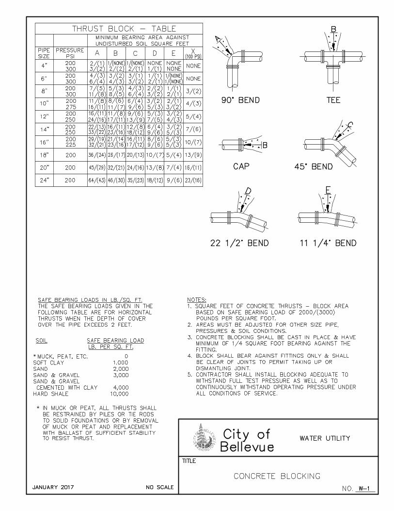
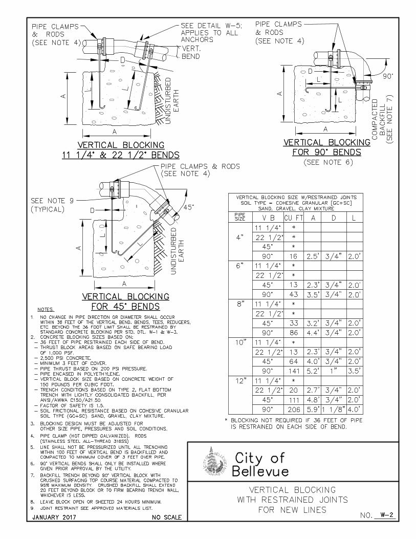
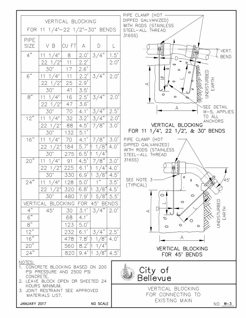
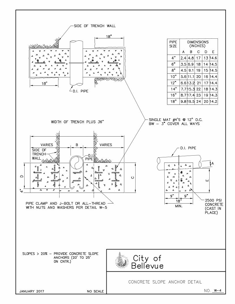
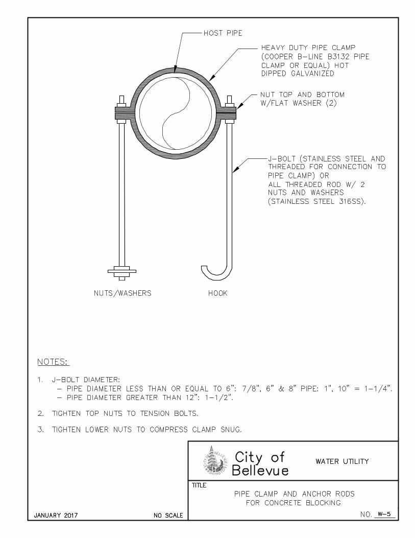
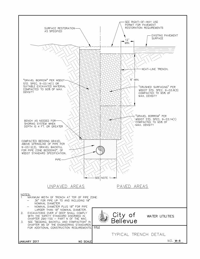
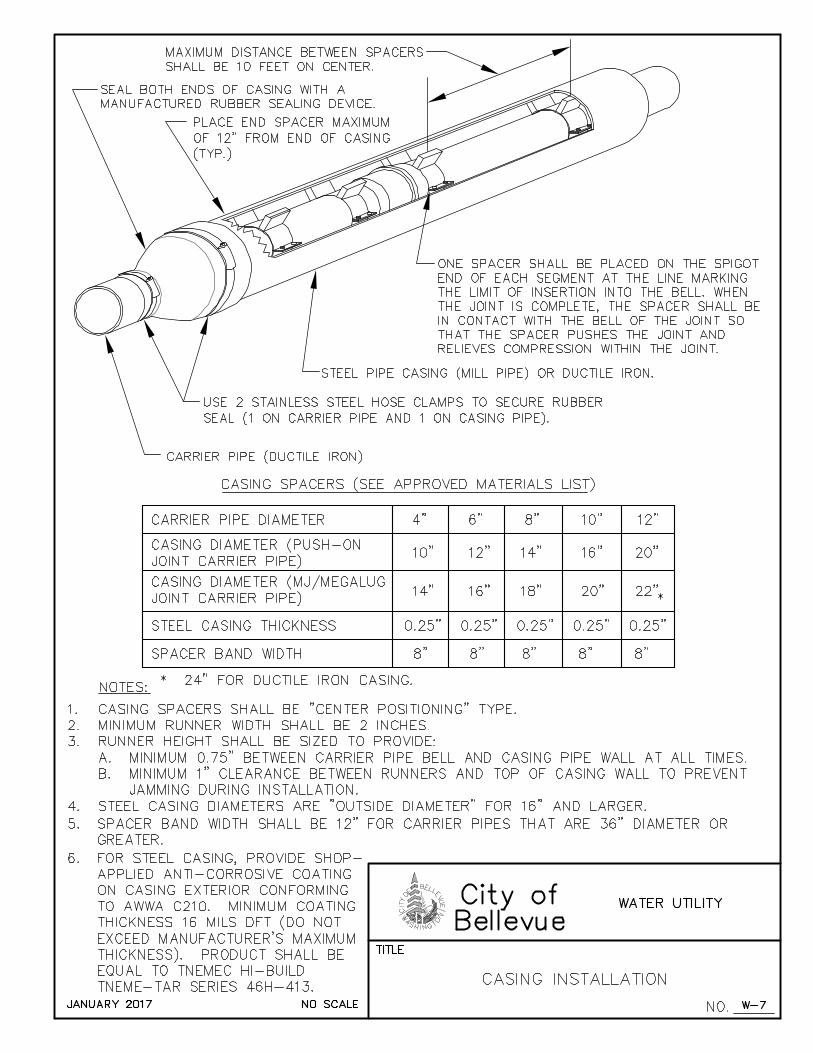
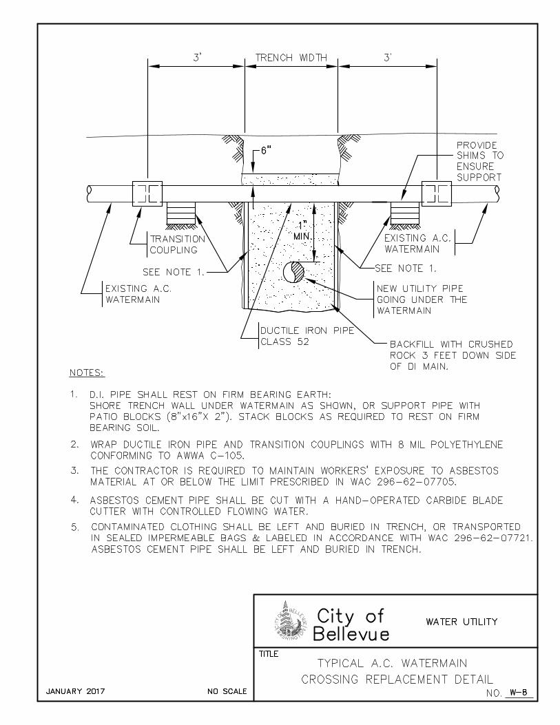
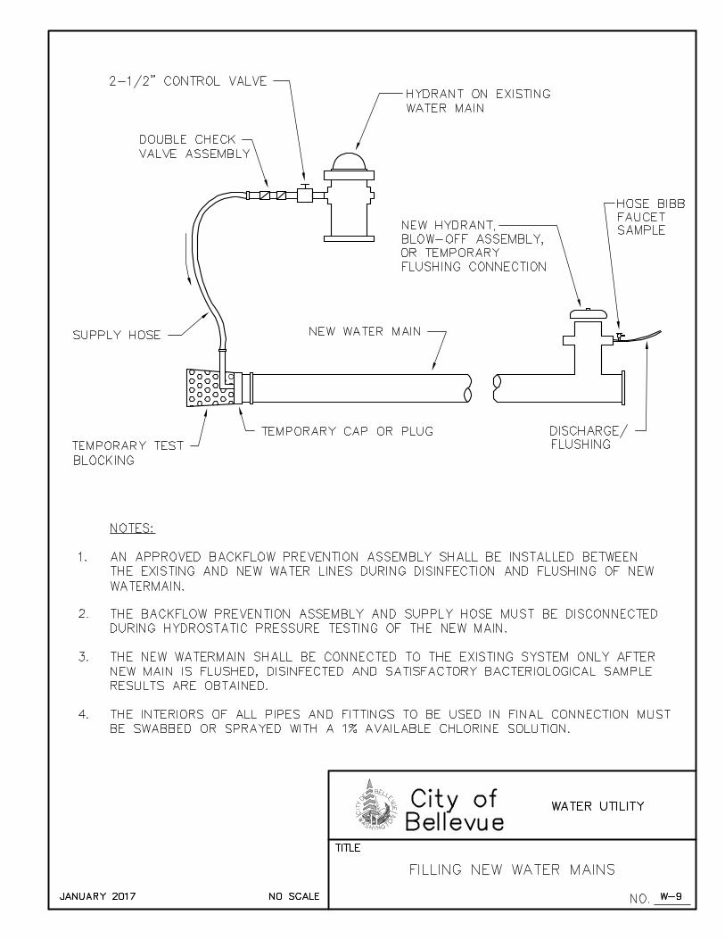
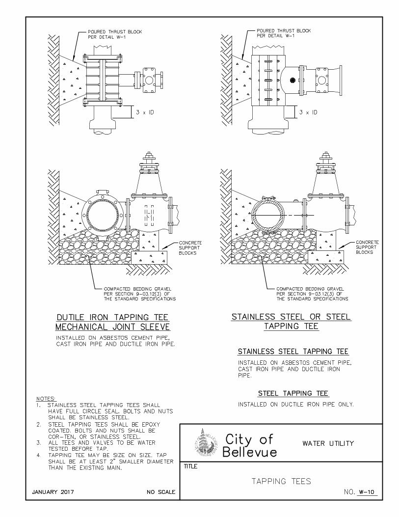
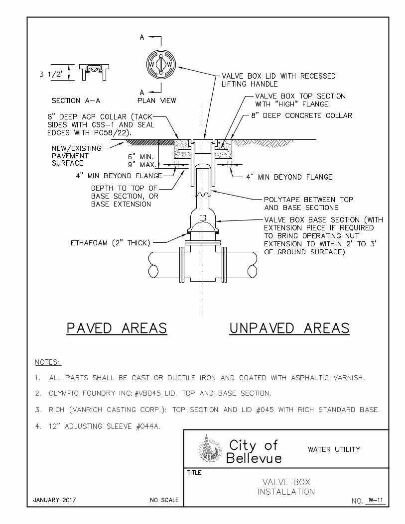
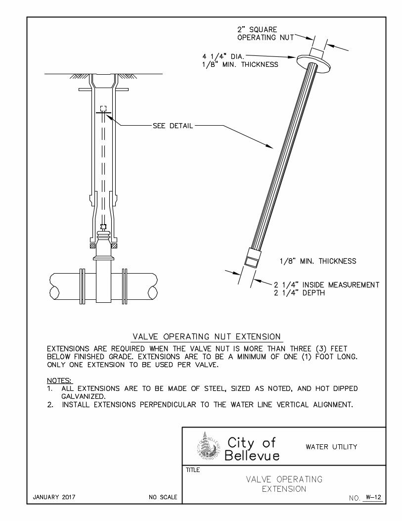
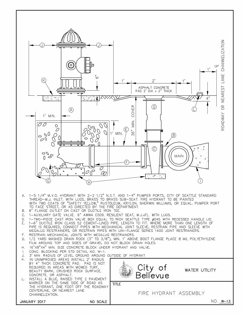

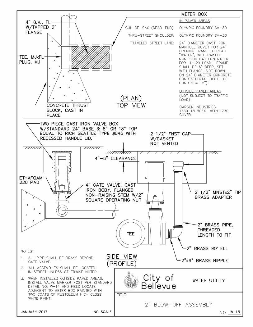
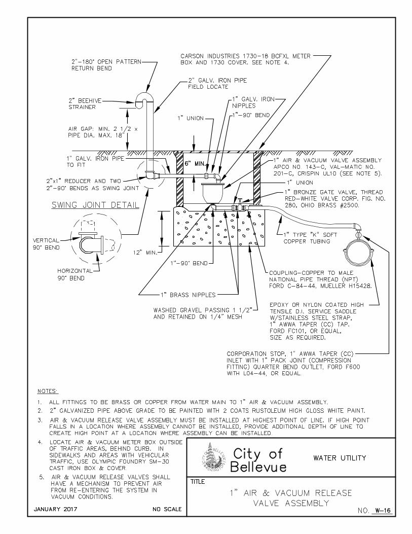
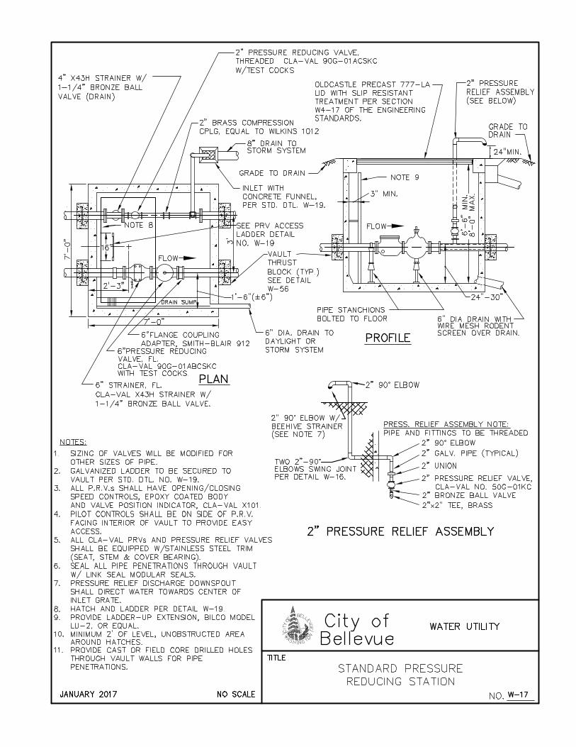
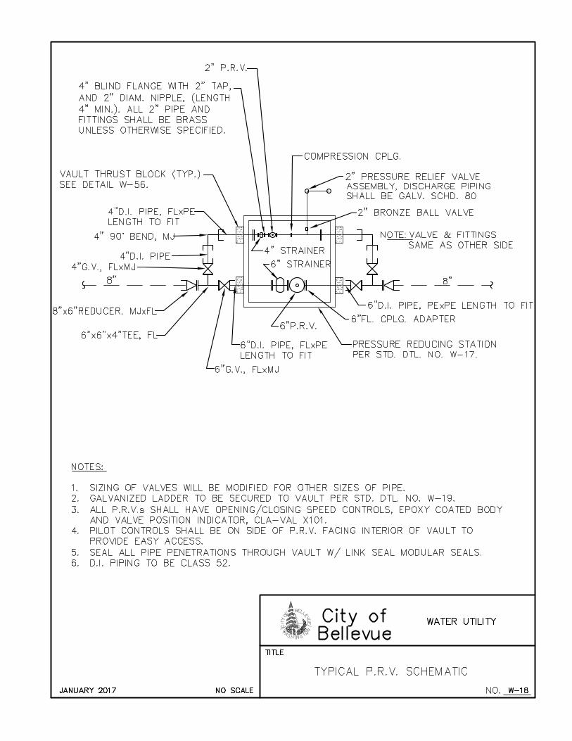
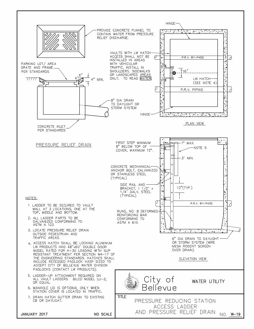
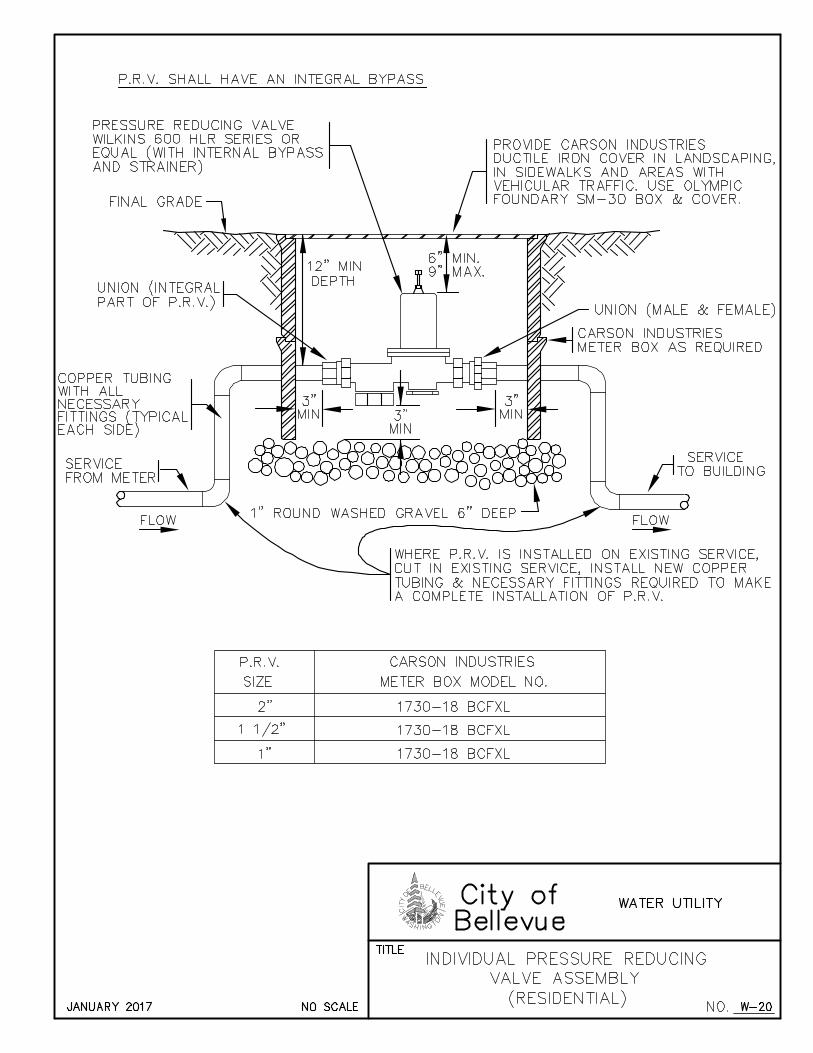
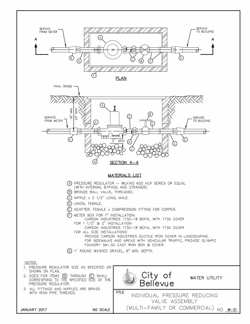
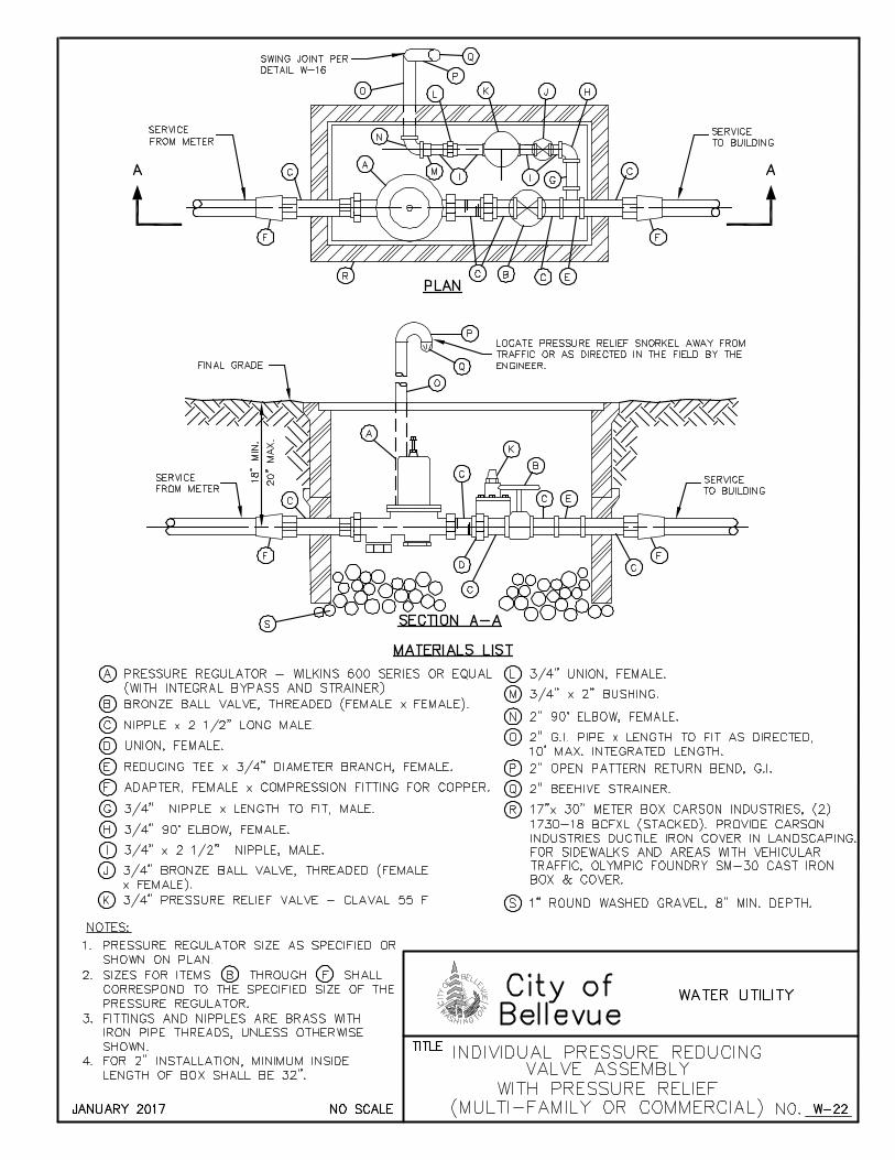
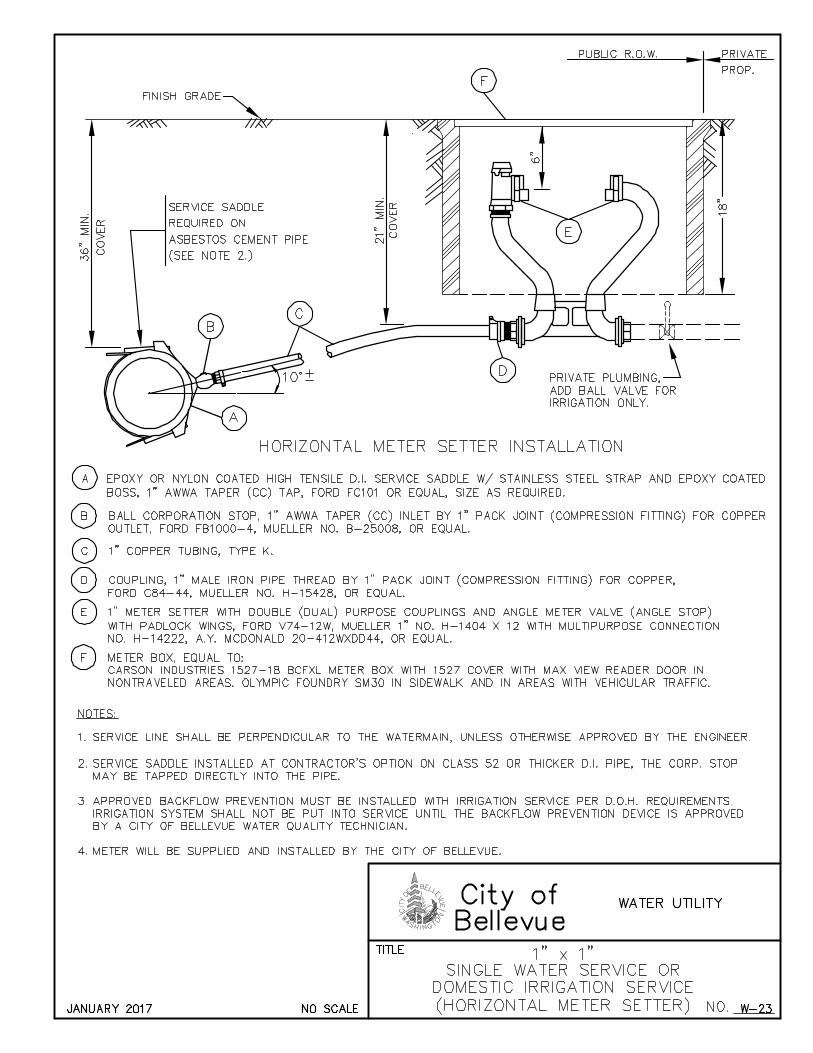
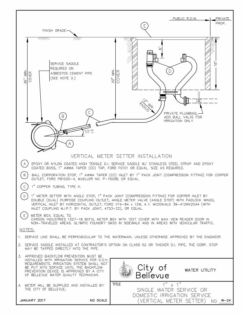
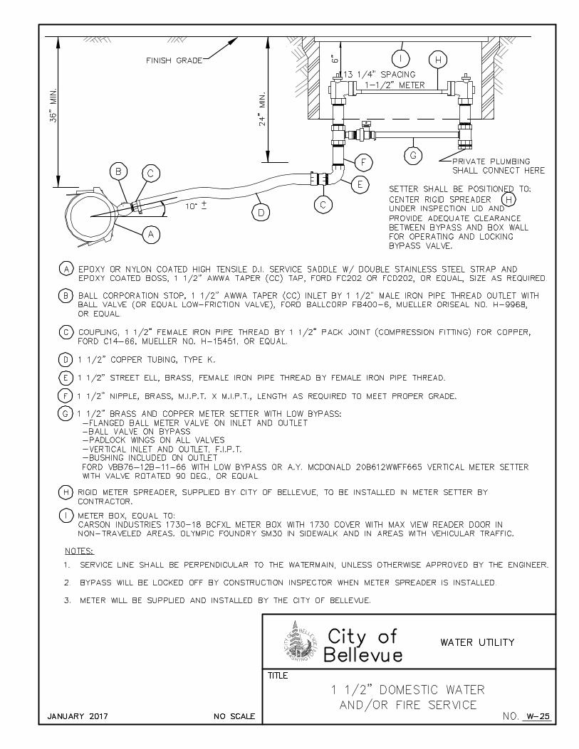
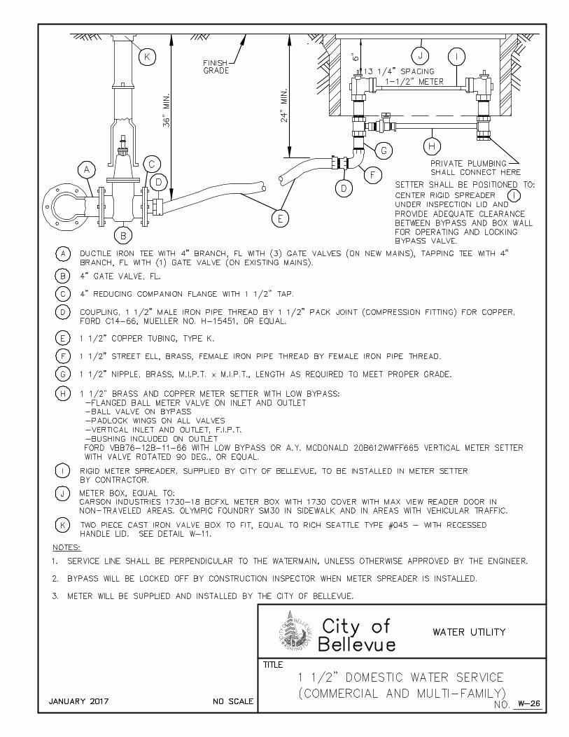
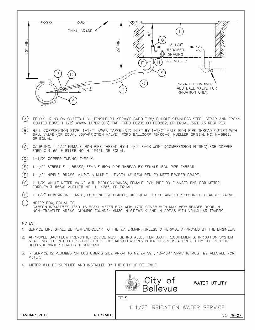
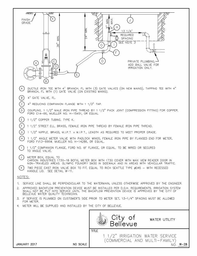
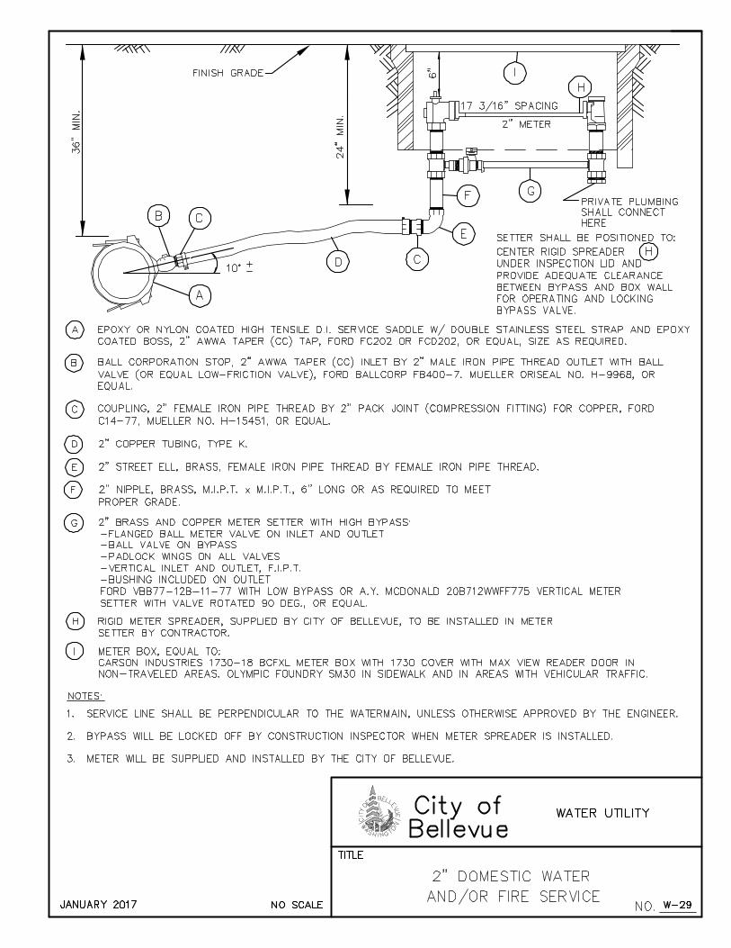
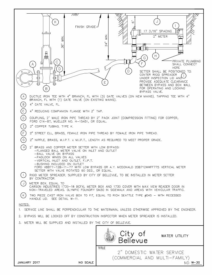
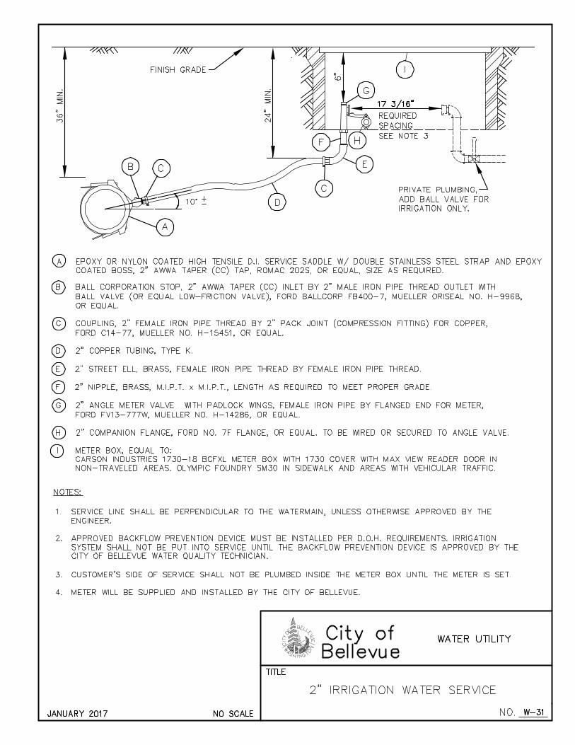
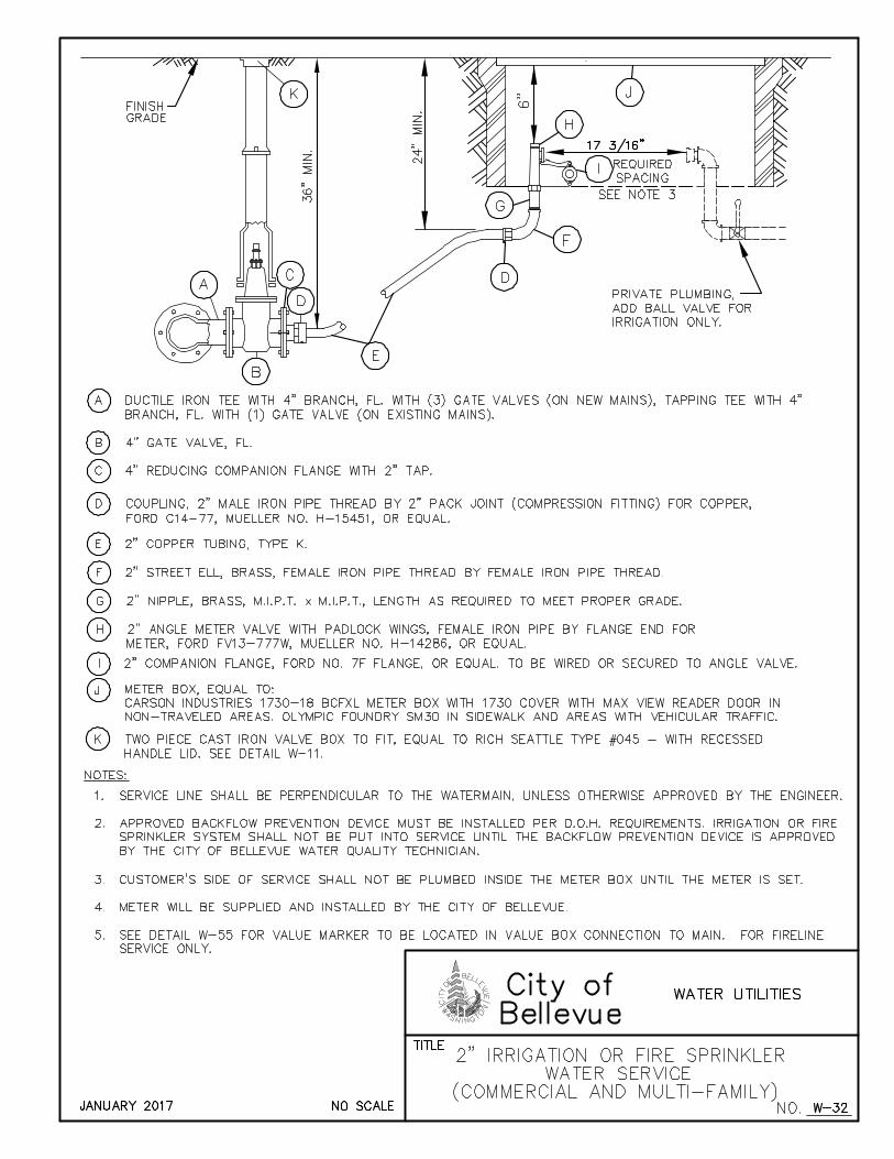
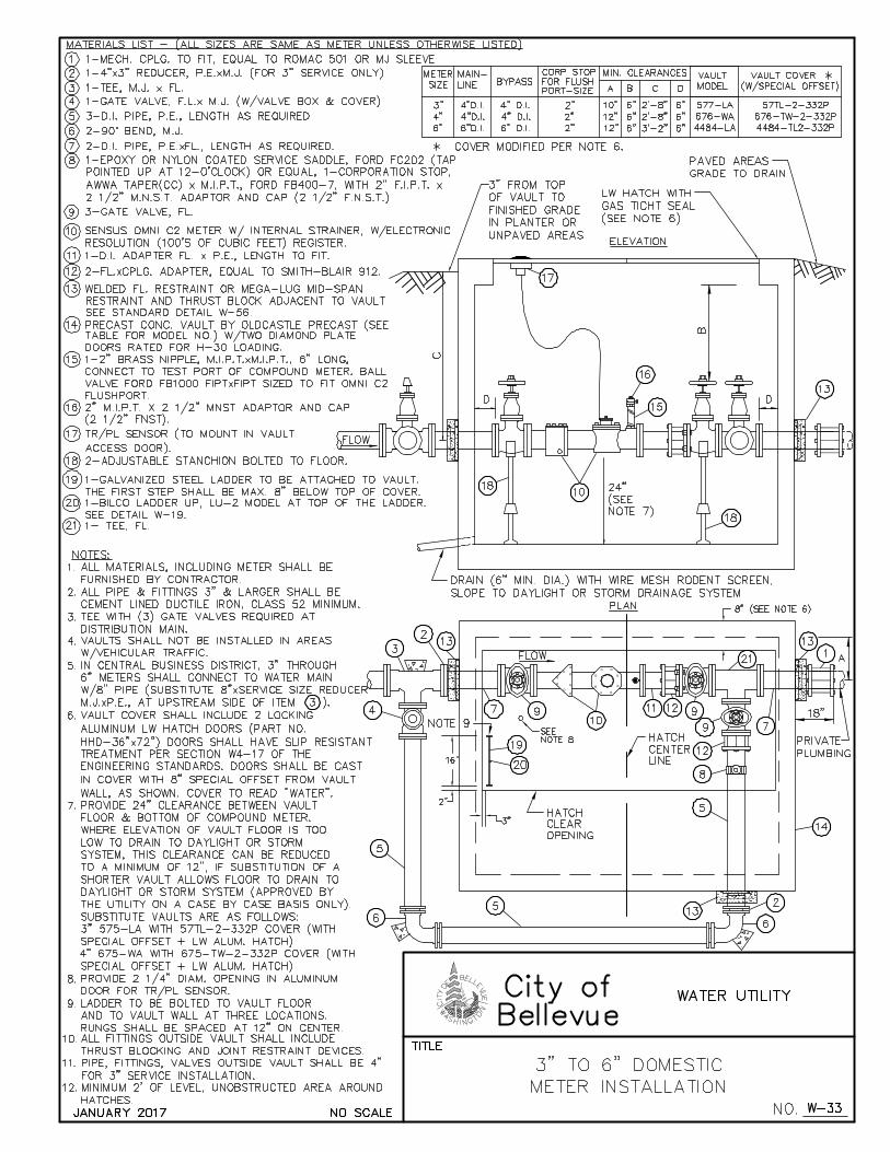
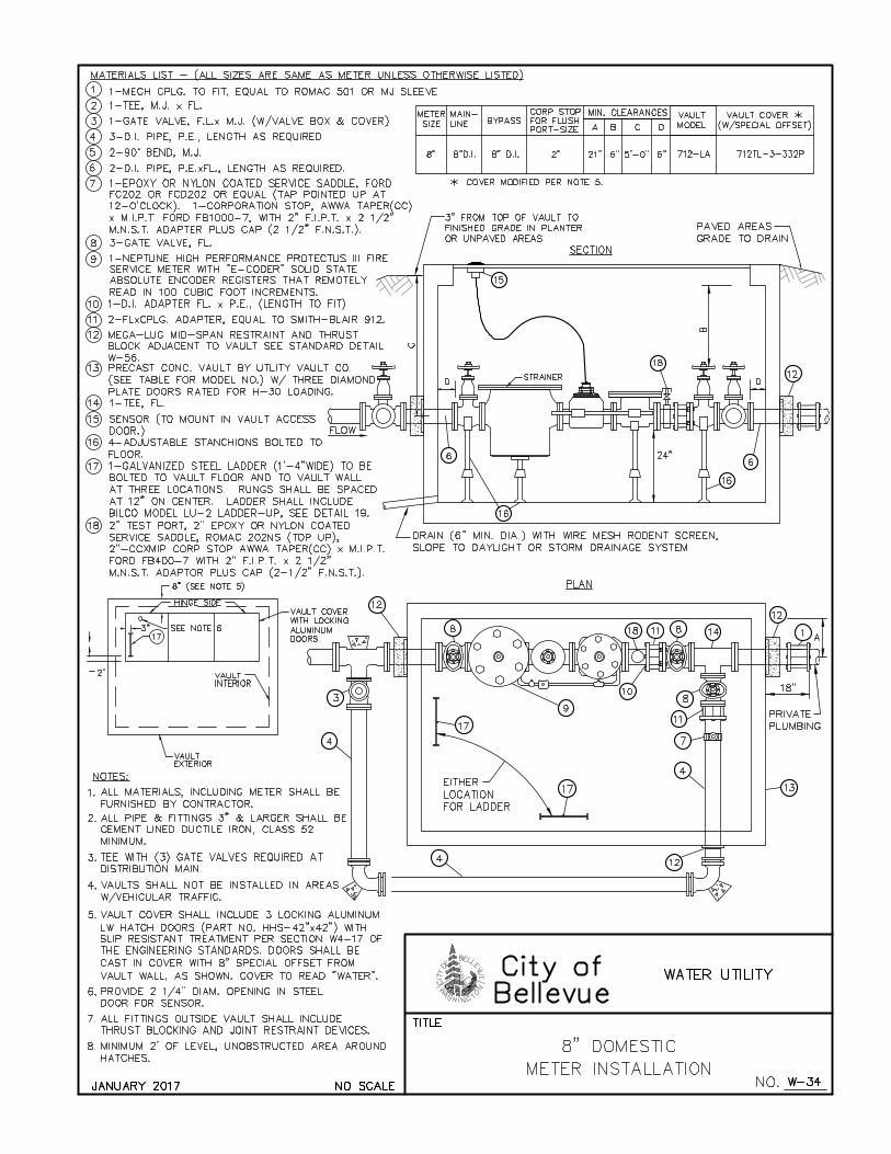
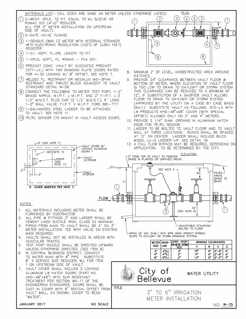
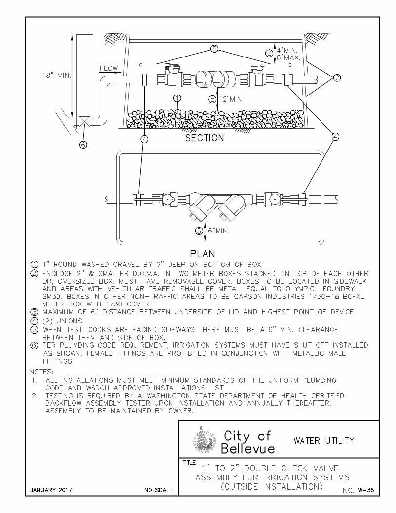

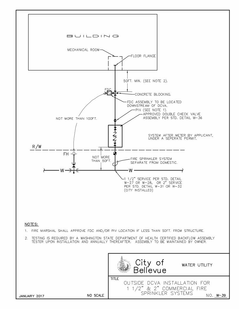
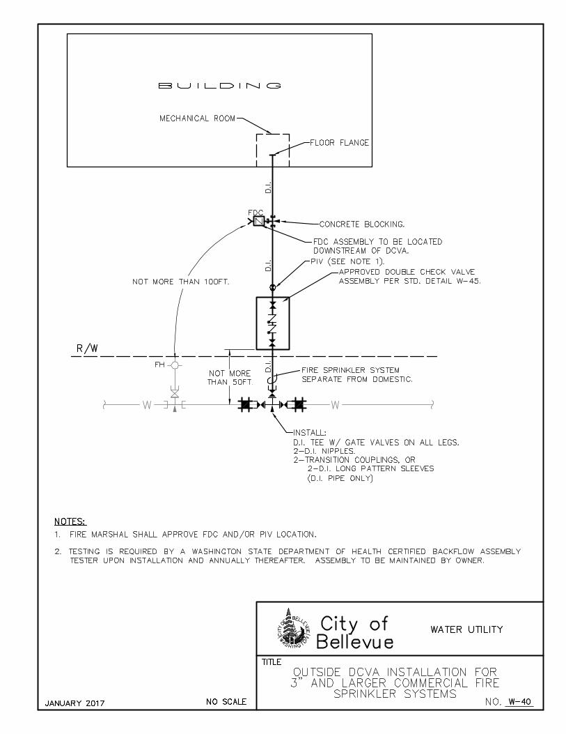
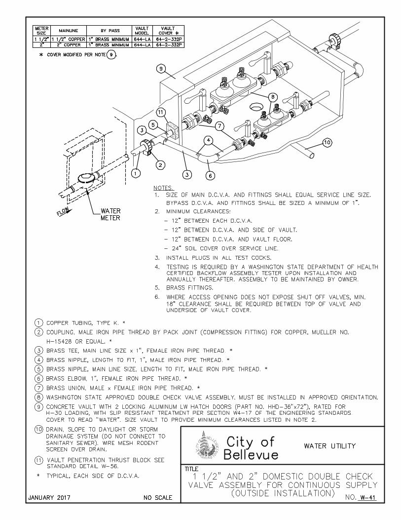
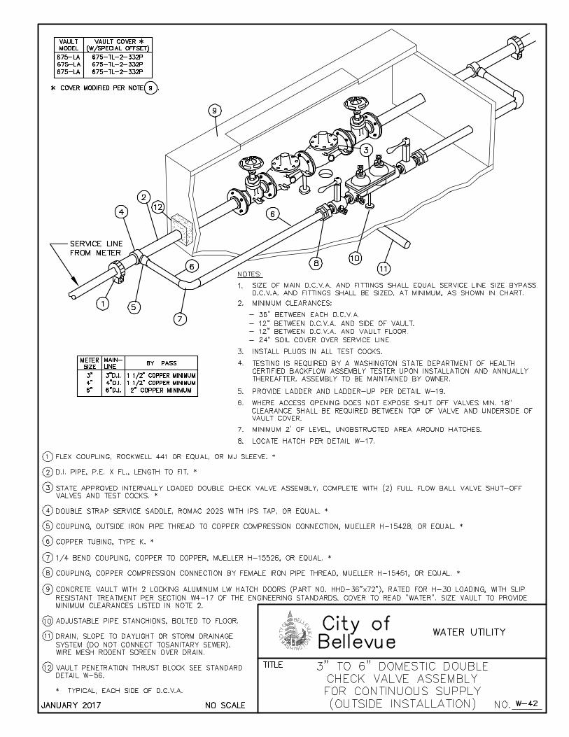
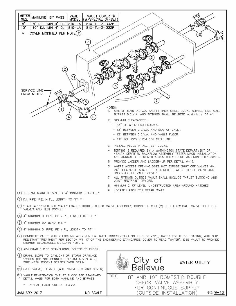
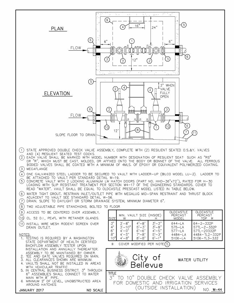
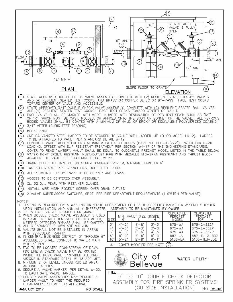
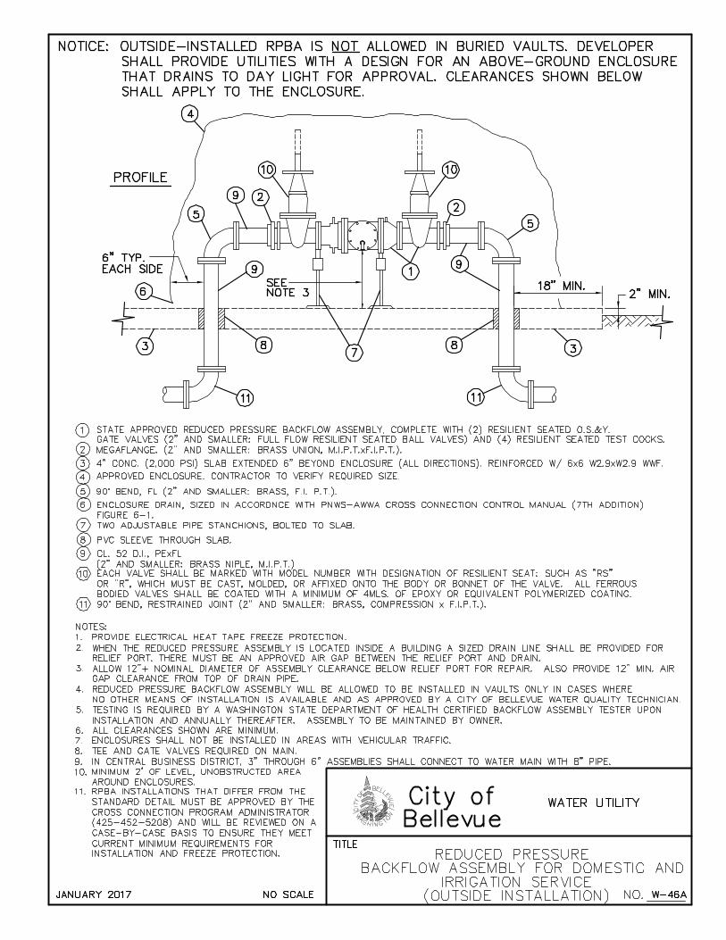
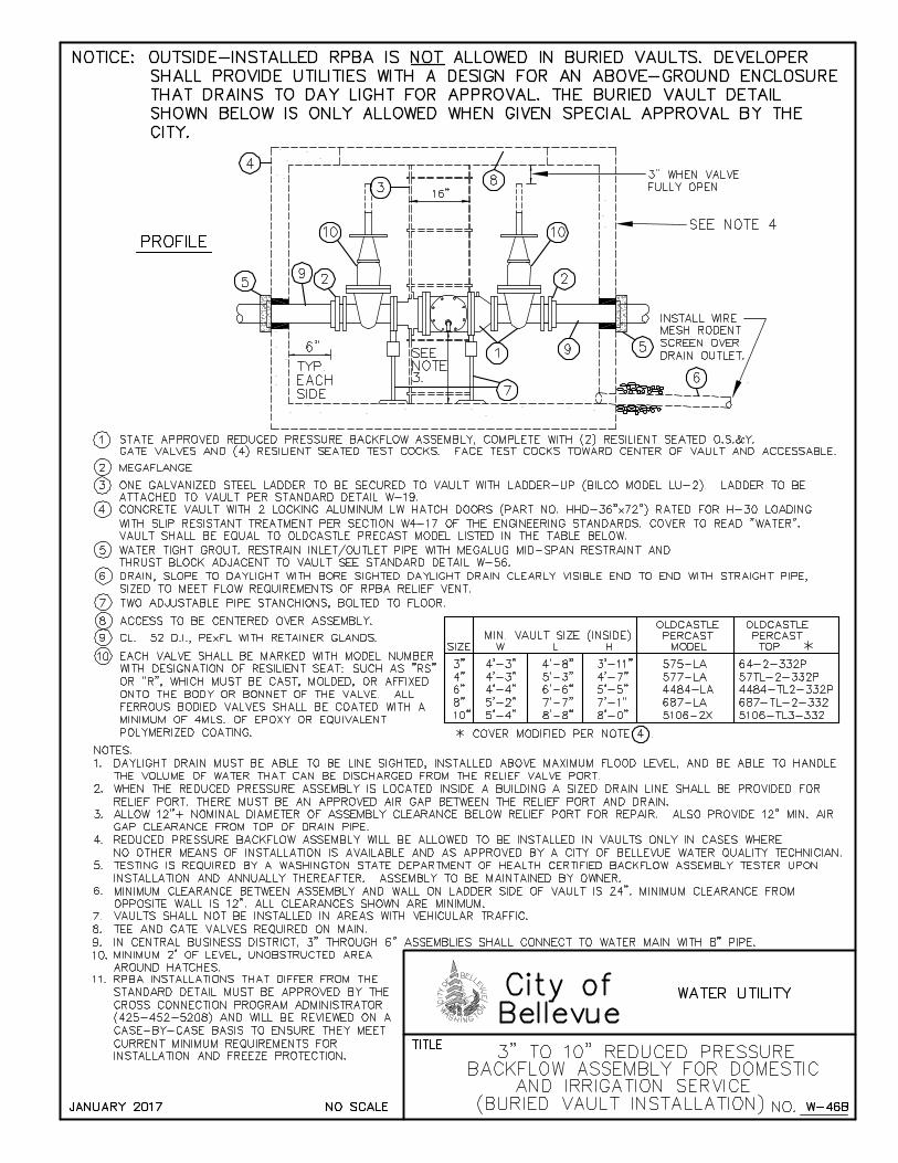
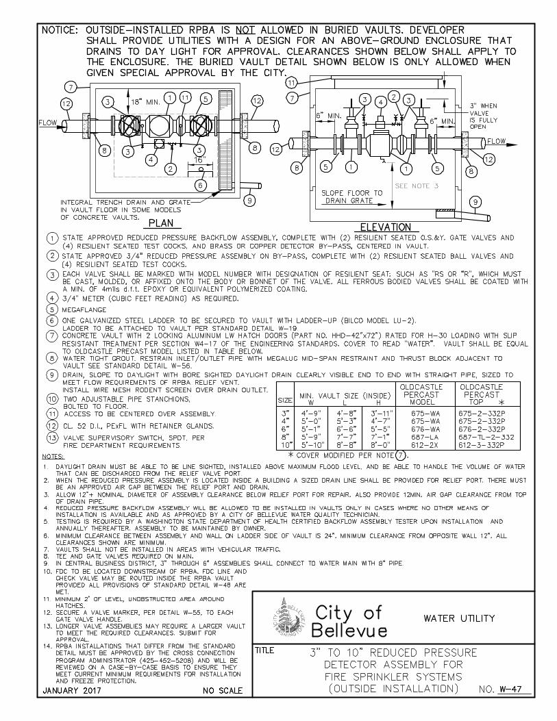
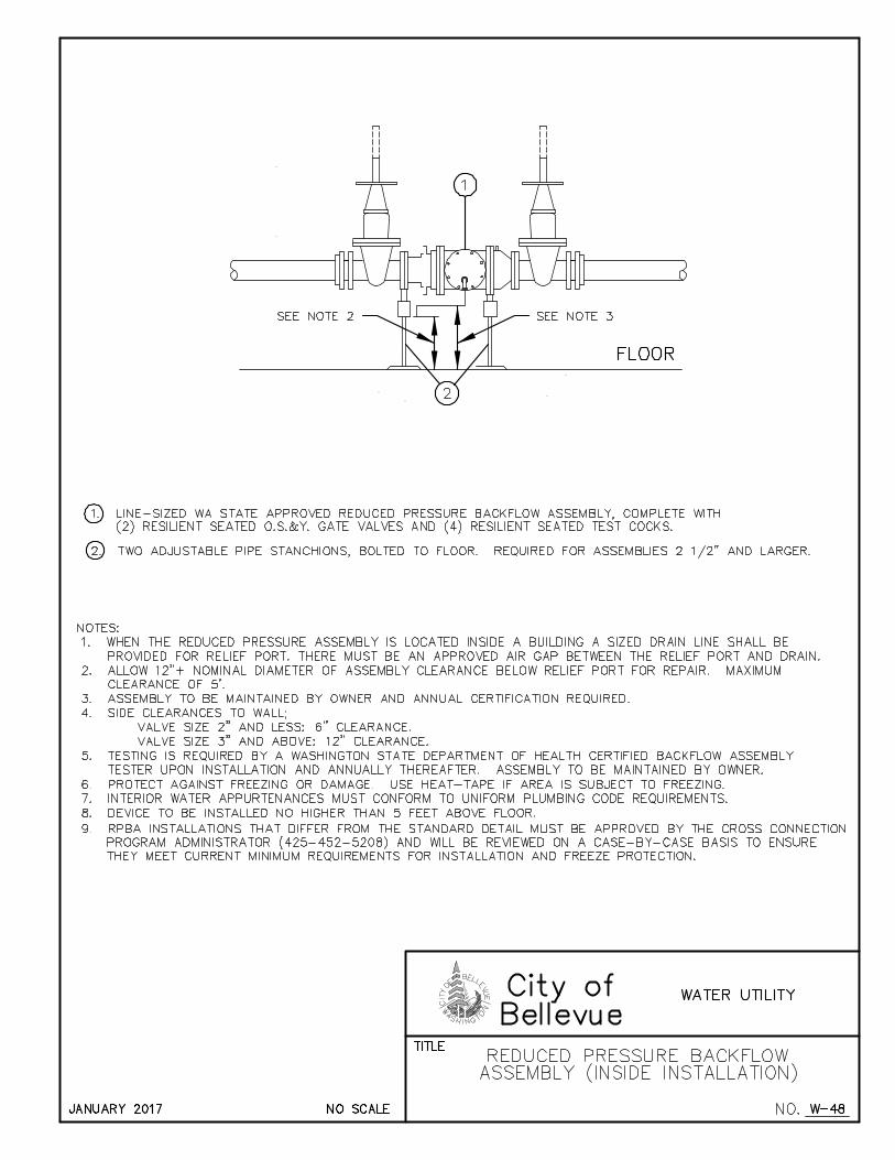
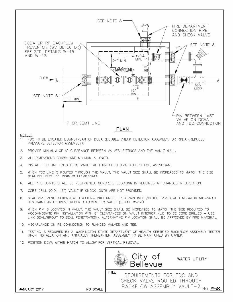
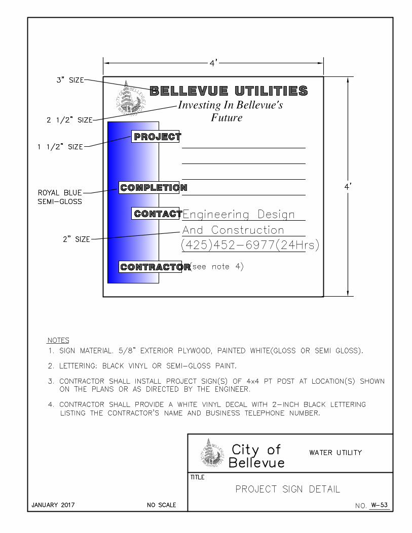
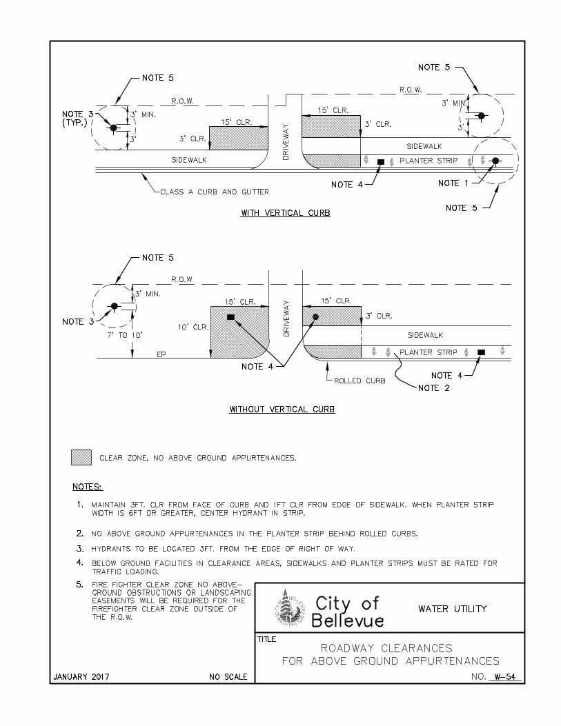
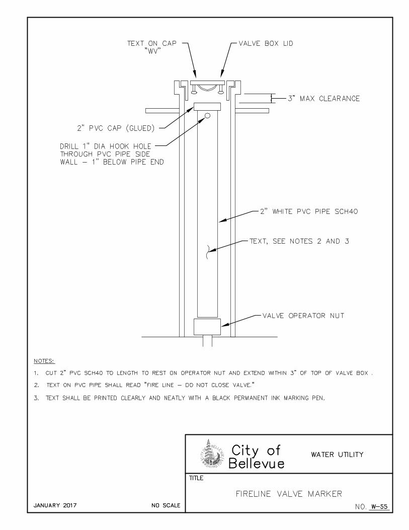
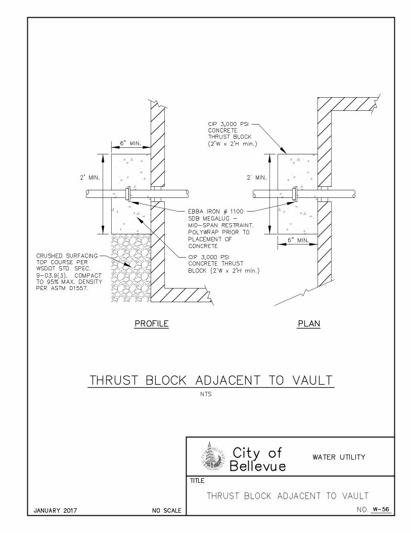
WATER ENGINEERING STANDARDS JANUARY 2017
APPENDIX W-2
DRAFTING STANDARDS
Also available in AutoCAD format at:
http://www.bellevuewa.gov/utilities_maps_forms.htm
WATER SYMBOLS ............................................................................................................. A(W2 -1)
SANITARY/STORM SEWER SYMBOLS .......................................................................... A(W2 -2)
SURVEY SYMBOLS ............................................................................................................ A(W2 -3)
SURFACE FEATURES/LANDSCAPE SYMBOLS ............................................................ A(W2 -4)
SIGNALIZATION SYMBOLS ............................................................................................. A(W2 -5)
CHANNELIZATION SYMBOLS ........................................................................................ A(W2 -7)
GAS/POWER/TELEPHONE SYMBOLS ............................................................................ A(W2 -8)
SURFACE FEATURES LINETYPES ................................................................................... A(W2-9)
SURVEY LINETYPES ........................................................................................................ A(W2-10)
UTILITIES LINETYPES ..................................................................................................... A(W2-11)
TEXT STYLES ..................................................................................................................... A(W2-12)
NOTES .................................................................................................................................. A(W2-12)
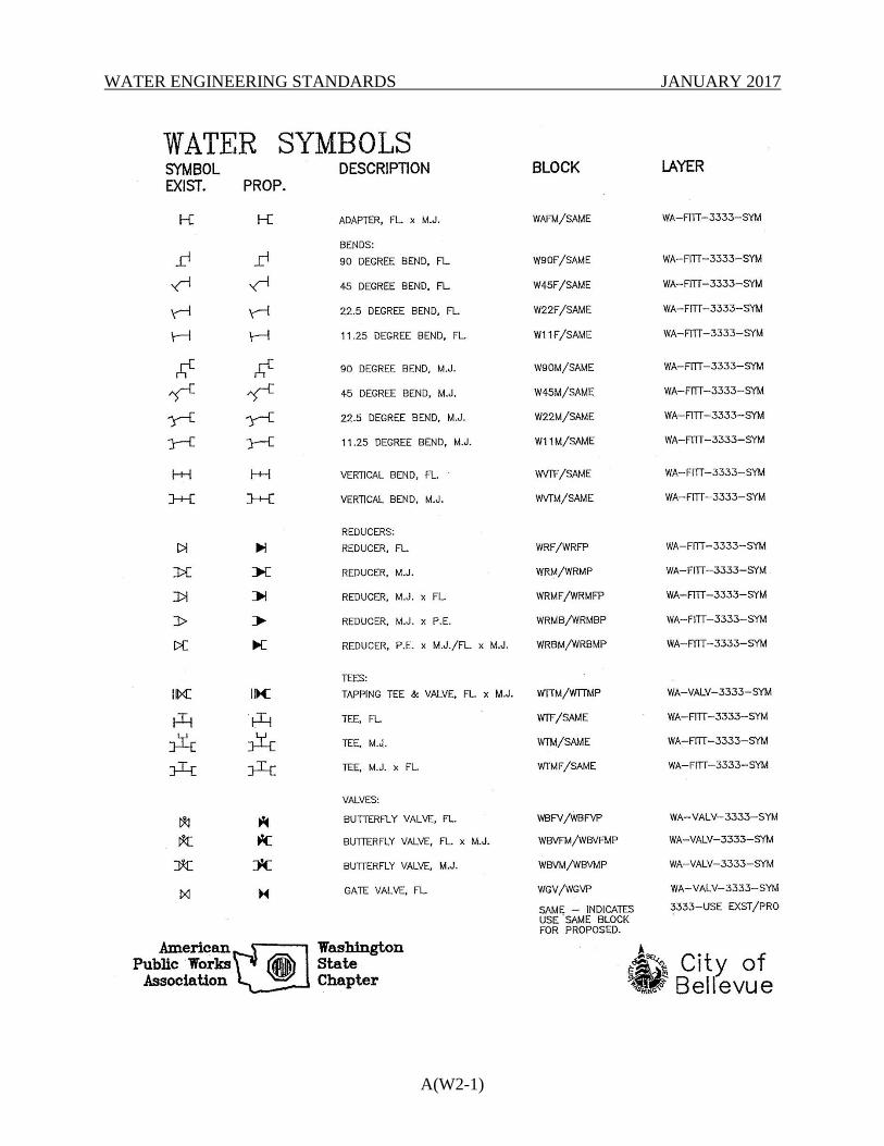
WATER ENGINEERING STANDARDS JANUARY 2017
A(W2-1)
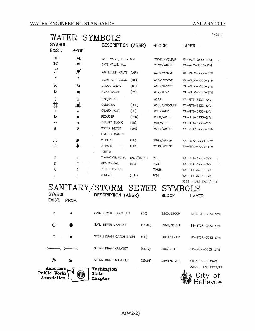
WATER ENGINEERING STANDARDS JANUARY 2017
A(W2-2)
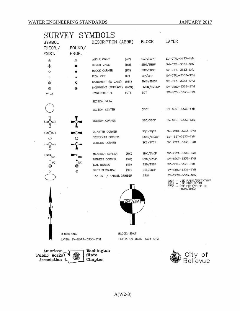
WATER ENGINEERING STANDARDS JANUARY 2017
A(W2-3)
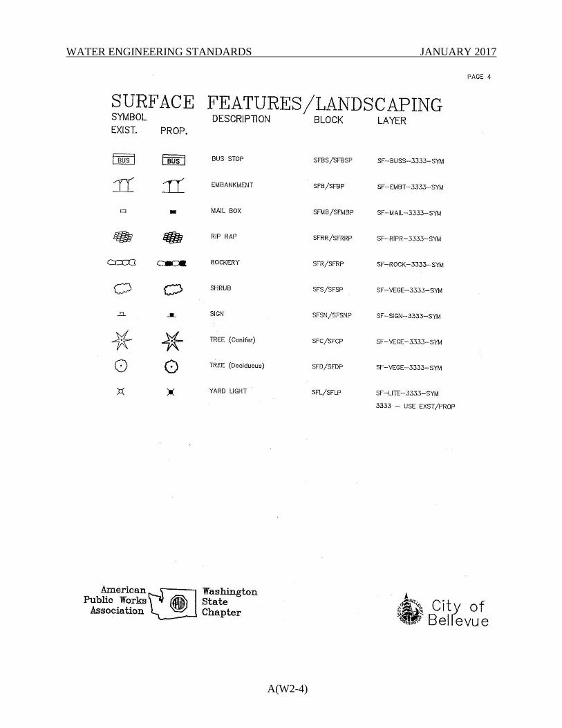
WATER ENGINEERING STANDARDS JANUARY 2017
A(W2-4)
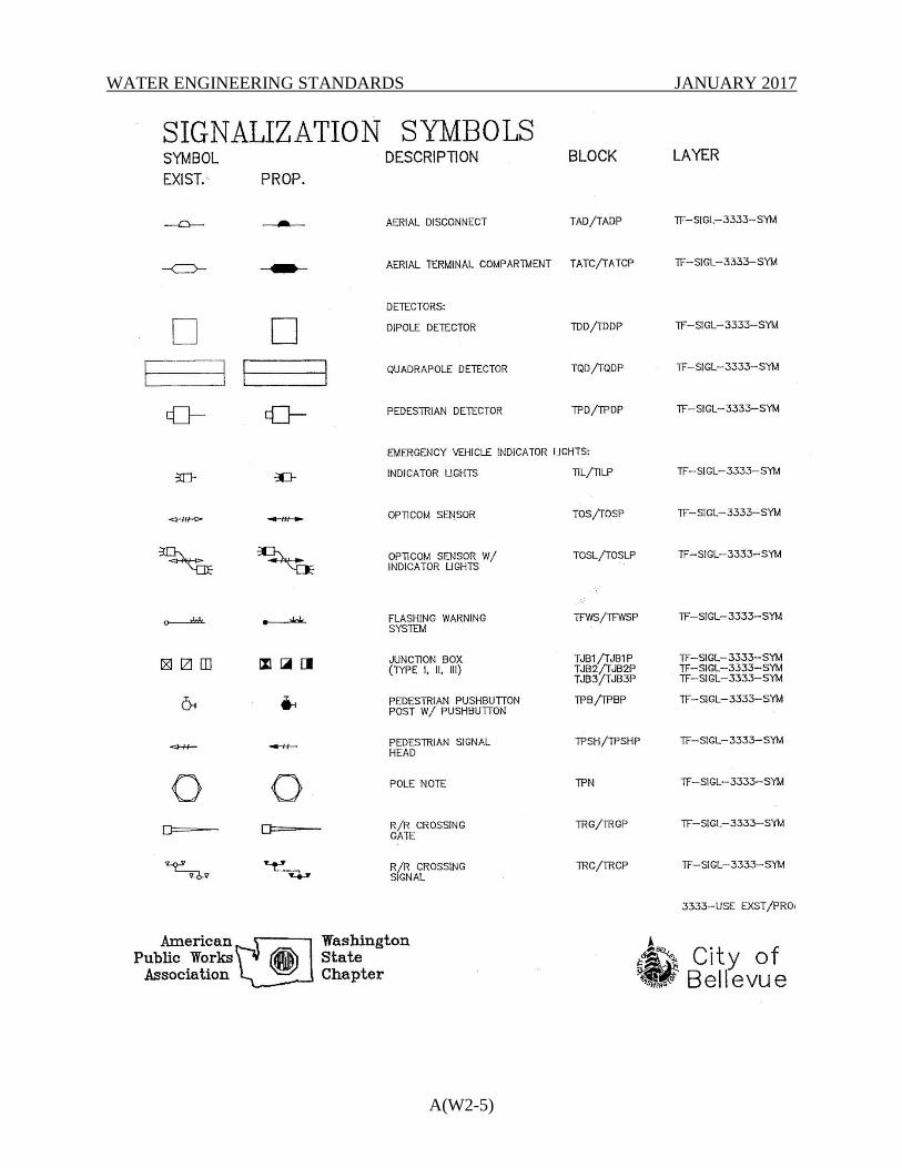
WATER ENGINEERING STANDARDS JANUARY 2017
A(W2-5)
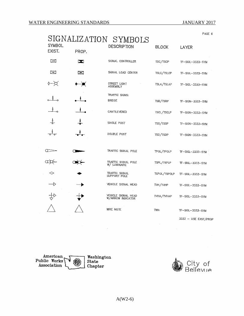
WATER ENGINEERING STANDARDS JANUARY 2017
A(W2-6)
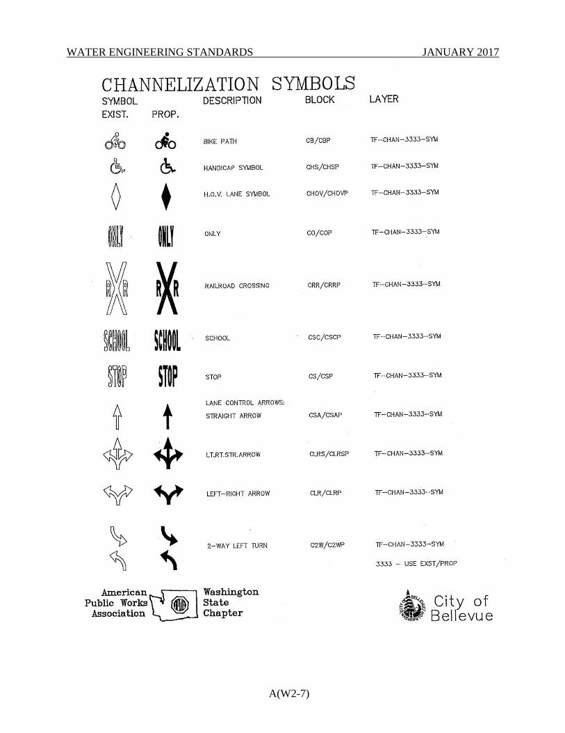
WATER ENGINEERING STANDARDS JANUARY 2017
A(W2-7)
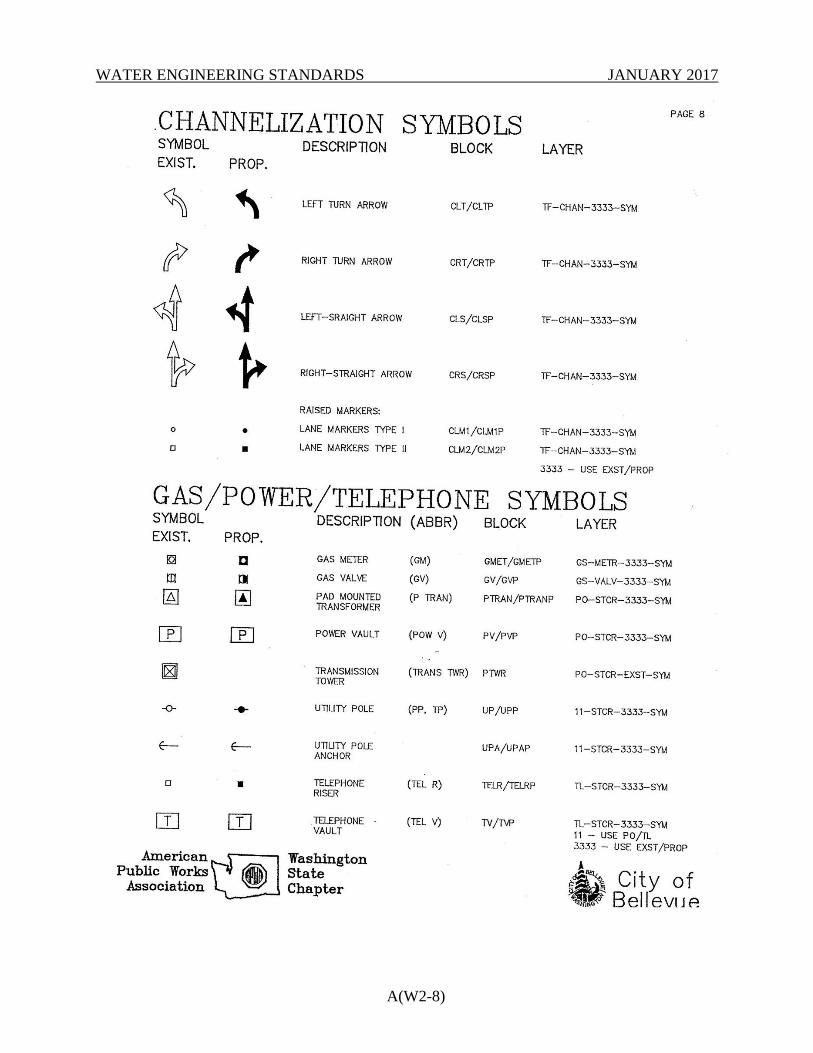
WATER ENGINEERING STANDARDS JANUARY 2017
A(W2-8)
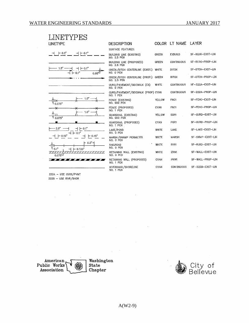
WATER ENGINEERING STANDARDS JANUARY 2017
A(W2-9)
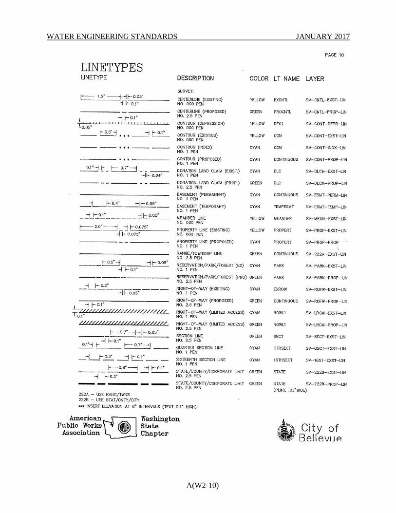
WATER ENGINEERING STANDARDS JANUARY 2017
A(W2-10)
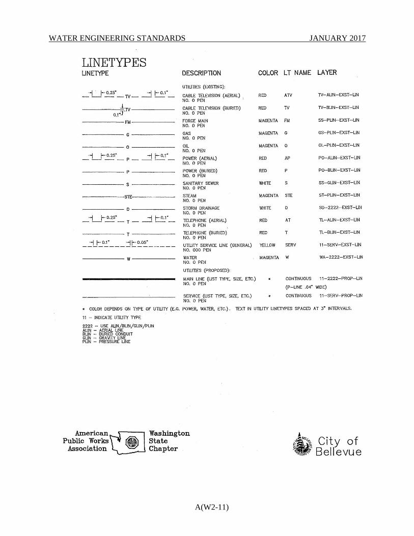
WATER ENGINEERING STANDARDS JANUARY 2017
A(W2-11)
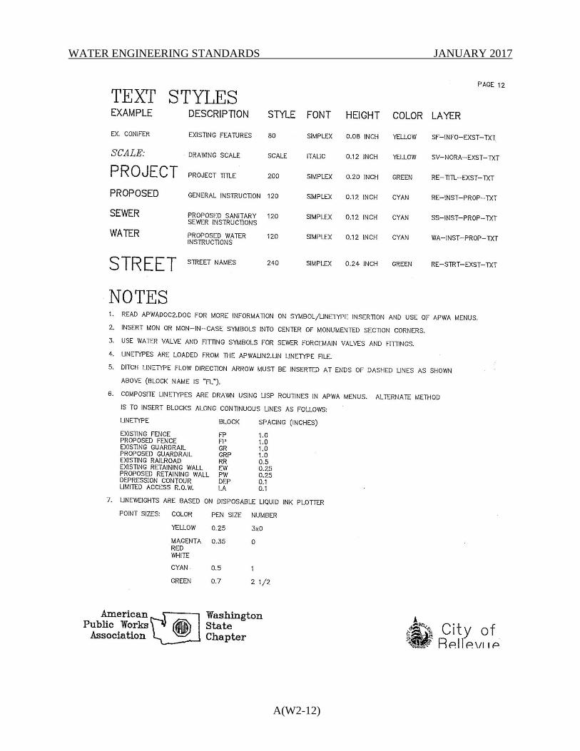
WATER ENGINEERING STANDARDS JANUARY 2017
A(W2-12)
WATER ENGINEERING STANDARDS JANUARY 2017
A(W3 – 1)
APPENDIX W-3
SAMPLE TITLE BLOCK
Also available in AutoCAD format at:
http://www.bellevuewa.gov/utilities_maps_forms.htm
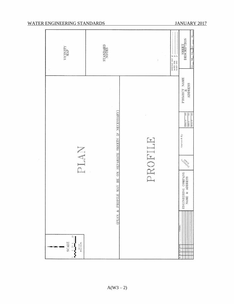
WATER ENGINEERING STANDARDS JANUARY 2017
A(W3 – 2)
WATER ENGINEERING STANDARDS JANUARY 2017
A(W3 – 3)
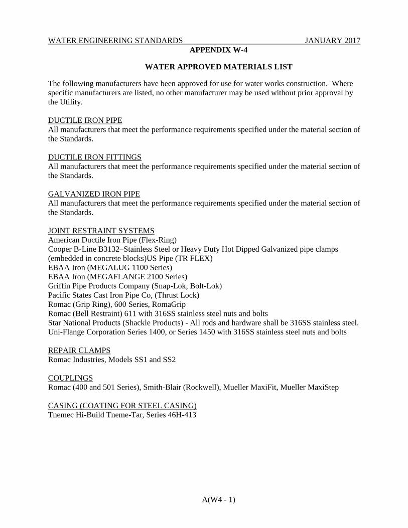
WATER ENGINEERING STANDARDS JANUARY 2017
A(W4 - 1)
APPENDIX W-4
WATER APPROVED MATERIALS LIST
The following manufacturers have been approved for use for water works construction. Where
specific manufacturers are listed, no other manufacturer may be used without prior approval by
the Utility.
DUCTILE IRON PIPE
All manufacturers that meet the performance requirements specified under the material section of
the Standards.
DUCTILE IRON FITTINGS
All manufacturers that meet the performance requirements specified under the material section of
the Standards.
GALVANIZED IRON PIPE
All manufacturers that meet the performance requirements specified under the material section of
the Standards.
JOINT RESTRAINT SYSTEMS
American Ductile Iron Pipe (Flex-Ring)
Cooper B-Line B3132–Stainless Steel or Heavy Duty Hot Dipped Galvanized pipe clamps
(embedded in concrete blocks)US Pipe (TR FLEX)
EBAA Iron (MEGALUG 1100 Series)
EBAA Iron (MEGAFLANGE 2100 Series)
Griffin Pipe Products Company (Snap-Lok, Bolt-Lok)
Pacific States Cast Iron Pipe Co, (Thrust Lock)
Romac (Grip Ring), 600 Series, RomaGrip
Romac (Bell Restraint) 611 with 316SS stainless steel nuts and bolts
Star National Products (Shackle Products) - All rods and hardware shall be 316SS stainless steel.
Uni-Flange Corporation Series 1400, or Series 1450 with 316SS stainless steel nuts and bolts
REPAIR CLAMPS
Romac Industries, Models SS1 and SS2
COUPLINGS
Romac (400 and 501 Series), Smith-Blair (Rockwell), Mueller MaxiFit, Mueller MaxiStep
CASING (COATING FOR STEEL CASING)
Tnemec Hi-Build Tneme-Tar, Series 46H-413
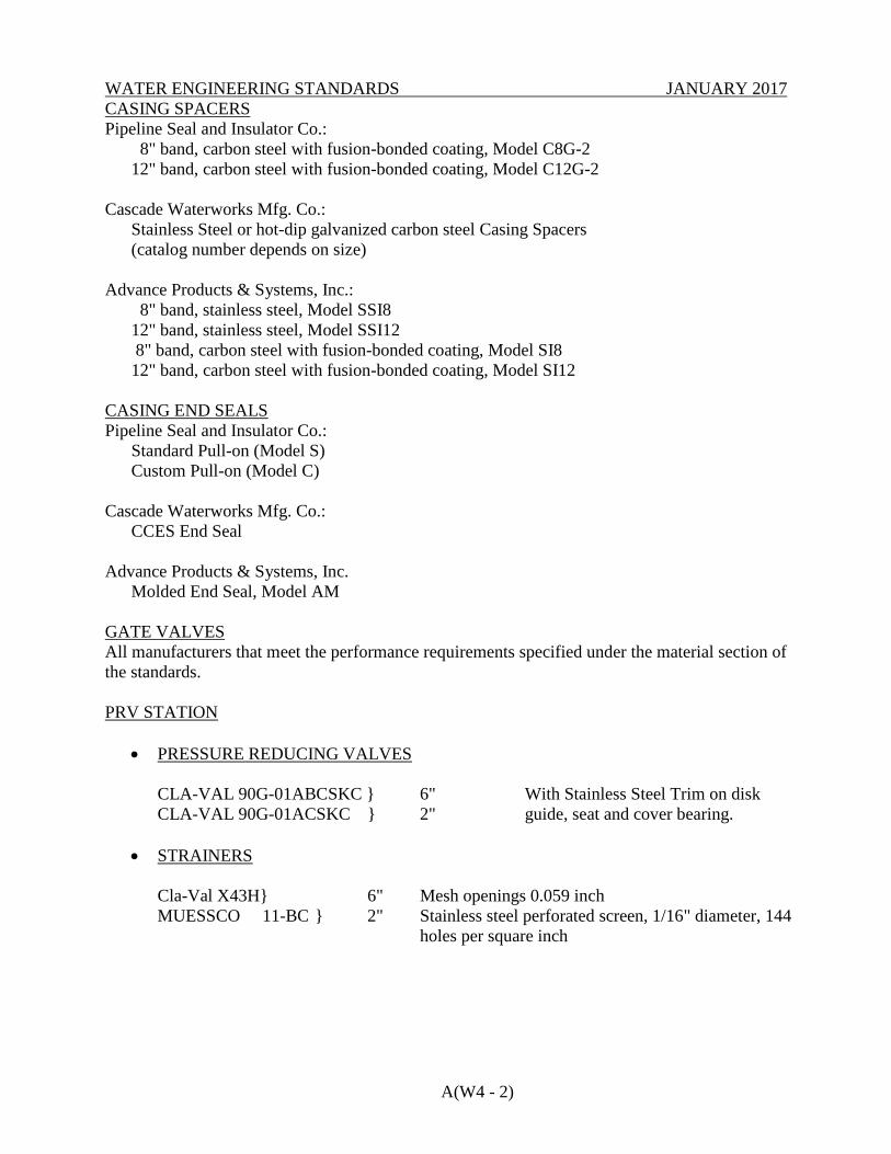
WATER ENGINEERING STANDARDS JANUARY 2017
A(W4 - 2)
CASING SPACERS
Pipeline Seal and Insulator Co.:
8" band, carbon steel with fusion-bonded coating, Model C8G-2
12" band, carbon steel with fusion-bonded coating, Model C12G-2
Cascade Waterworks Mfg. Co.:
Stainless Steel or hot-dip galvanized carbon steel Casing Spacers
(catalog number depends on size)
Advance Products & Systems, Inc.:
8" band, stainless steel, Model SSI8
12" band, stainless steel, Model SSI12
8" band, carbon steel with fusion-bonded coating, Model SI8
12" band, carbon steel with fusion-bonded coating, Model SI12
CASING END SEALS
Pipeline Seal and Insulator Co.:
Standard Pull-on (Model S)
Custom Pull-on (Model C)
Cascade Waterworks Mfg. Co.:
CCES End Seal
Advance Products & Systems, Inc.
Molded End Seal, Model AM
GATE VALVES
All manufacturers that meet the performance requirements specified under the material section of
the standards.
PRV STATION
PRESSURE REDUCING VALVES
CLA-VAL 90G-01ABCSKC } 6" With Stainless Steel Trim on disk
CLA-VAL 90G-01ACSKC } 2" guide, seat and cover bearing.
STRAINERS
Cla-Val X43H} 6" Mesh openings 0.059 inch
MUESSCO 11-BC } 2" Stainless steel perforated screen, 1/16" diameter, 144
holes per square inch
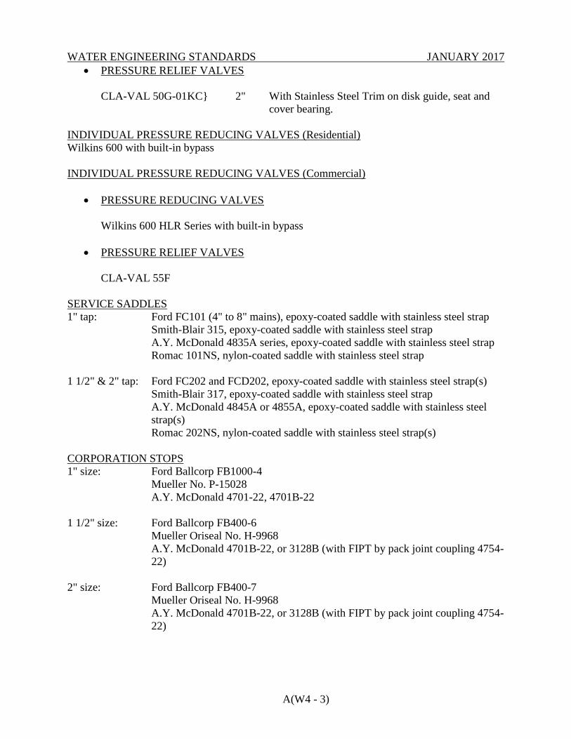
WATER ENGINEERING STANDARDS JANUARY 2017
A(W4 - 3)
PRESSURE RELIEF VALVES
CLA-VAL 50G-01KC} 2" With Stainless Steel Trim on disk guide, seat and
cover bearing.
INDIVIDUAL PRESSURE REDUCING VALVES (Residential)
Wilkins 600 with built-in bypass
INDIVIDUAL PRESSURE REDUCING VALVES (Commercial)
PRESSURE REDUCING VALVES
Wilkins 600 HLR Series with built-in bypass
PRESSURE RELIEF VALVES
CLA-VAL 55F
SERVICE SADDLES
1" tap: Ford FC101 (4" to 8" mains), epoxy-coated saddle with stainless steel strap
Smith-Blair 315, epoxy-coated saddle with stainless steel strap
A.Y. McDonald 4835A series, epoxy-coated saddle with stainless steel strap
Romac 101NS, nylon-coated saddle with stainless steel strap
1 1/2" & 2" tap: Ford FC202 and FCD202, epoxy-coated saddle with stainless steel strap(s)
Smith-Blair 317, epoxy-coated saddle with stainless steel strap
A.Y. McDonald 4845A or 4855A, epoxy-coated saddle with stainless steel
strap(s)
Romac 202NS, nylon-coated saddle with stainless steel strap(s)
CORPORATION STOPS
1" size: Ford Ballcorp FB1000-4
Mueller No. P-15028
A.Y. McDonald 4701-22, 4701B-22
1 1/2" size: Ford Ballcorp FB400-6
Mueller Oriseal No. H-9968
A.Y. McDonald 4701B-22, or 3128B (with FIPT by pack joint coupling 4754-
22)
2" size: Ford Ballcorp FB400-7
Mueller Oriseal No. H-9968
A.Y. McDonald 4701B-22, or 3128B (with FIPT by pack joint coupling 4754-
22)
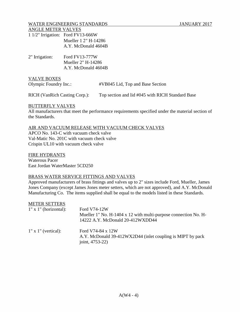
WATER ENGINEERING STANDARDS JANUARY 2017
A(W4 - 4)
ANGLE METER VALVES
1 1/2" Irrigation: Ford FV13-666W
Mueller 1 " H-14286
A.Y. McDonald 4604B
2" Irrigation: Ford FV13-777W
Mueller 2" H-14286
A.Y. McDonald 4604B
VALVE BOXES
Olympic Foundry Inc.: #VB045 Lid, Top and Base Section
RICH (VanRich Casting Corp.): Top section and lid #045 with RICH Standard Base
BUTTERFLY VALVES
All manufacturers that meet the performance requirements specified under the material section of
the Standards.
AIR AND VACUUM RELEASE WITH VACUUM CHECK VALVES
APCO No. 143-C with vacuum check valve
Val-Matic No. 201C with vacuum check valve
Crispin UL10 with vacuum check valve
FIRE HYDRANTS
Waterous Pacer
East Jordan WaterMaster 5CD250
BRASS WATER SERVICE FITTINGS AND VALVES
Approved manufacturers of brass fittings and valves up to 2" sizes include Ford, Mueller, James
Jones Company (except James Jones meter setters, which are not approved), and A.Y. McDonald
Manufacturing Co. The items supplied shall be equal to the models listed in these Standards.
METER SETTERS
1" x 1" (horizontal): Ford V74-12W
Mueller 1" No. H-1404 x 12 with multi-purpose connection No. H-
14222 A.Y. McDonald 20-412WXDD44
1" x 1" (vertical): Ford V74-84 x 12W
A.Y. McDonald 39-412WX2D44 (inlet coupling is MIPT by pack
joint, 4753-22)
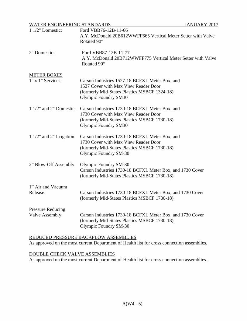
WATER ENGINEERING STANDARDS JANUARY 2017
A(W4 - 5)
1 1/2" Domestic: Ford VBB76-12B-11-66
A.Y. McDonald 20B612WWFF665 Vertical Meter Setter with Valve
Rotated 90°
2" Domestic: Ford VBB87-12B-11-77
A.Y. McDonald 20B712WWFF775 Vertical Meter Setter with Valve
Rotated 90°
METER BOXES
1" x 1" Services: Carson Industries 1527-18 BCFXL Meter Box, and
1527 Cover with Max View Reader Door
(formerly Mid-States Plastics MSBCF 1324-18)
Olympic Foundry SM30
1 1/2" and 2" Domestic: Carson Industries 1730-18 BCFXL Meter Box, and
1730 Cover with Max View Reader Door
(formerly Mid-States Plastics MSBCF 1730-18)
Olympic Foundry SM30
1 1/2" and 2" Irrigation: Carson Industries 1730-18 BCFXL Meter Box, and
1730 Cover with Max View Reader Door
(formerly Mid-States Plastics MSBCF 1730-18)
Olympic Foundry SM-30
2” Blow-Off Assembly: Olympic Foundry SM-30
Carson Industries 1730-18 BCFXL Meter Box, and 1730 Cover
(formerly Mid-States Plastics MSBCF 1730-18)
1” Air and Vacuum
Release: Carson Industries 1730-18 BCFXL Meter Box, and 1730 Cover
(formerly Mid-States Plastics MSBCF 1730-18)
Pressure Reducing
Valve Assembly: Carson Industries 1730-18 BCFXL Meter Box, and 1730 Cover
(formerly Mid-States Plastics MSBCF 1730-18)
Olympic Foundry SM-30
REDUCED PRESSURE BACKFLOW ASSEMBLIES
As approved on the most current Department of Health list for cross connection assemblies.
DOUBLE CHECK VALVE ASSEMBLIES
As approved on the most current Department of Health list for cross connection assemblies.
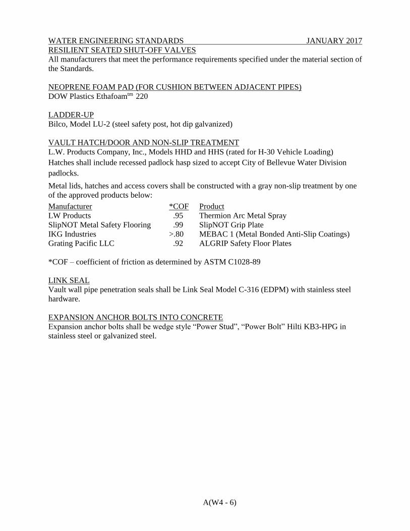
WATER ENGINEERING STANDARDS JANUARY 2017
A(W4 - 6)
RESILIENT SEATED SHUT-OFF VALVES
All manufacturers that meet the performance requirements specified under the material section of
the Standards.
NEOPRENE FOAM PAD (FOR CUSHION BETWEEN ADJACENT PIPES)
DOW Plastics Ethafoamtm 220
LADDER-UP
Bilco, Model LU-2 (steel safety post, hot dip galvanized)
VAULT HATCH/DOOR AND NON-SLIP TREATMENT
L.W. Products Company, Inc., Models HHD and HHS (rated for H-30 Vehicle Loading)
Hatches shall include recessed padlock hasp sized to accept City of Bellevue Water Division
padlocks.
Metal lids, hatches and access covers shall be constructed with a gray non-slip treatment by one
of the approved products below:
Manufacturer *COF Product
LW Products .95 Thermion Arc Metal Spray
SlipNOT Metal Safety Flooring .99 SlipNOT Grip Plate
IKG Industries >.80 MEBAC 1 (Metal Bonded Anti-Slip Coatings)
Grating Pacific LLC .92 ALGRIP Safety Floor Plates
*COF – coefficient of friction as determined by ASTM C1028-89
LINK SEAL
Vault wall pipe penetration seals shall be Link Seal Model C-316 (EDPM) with stainless steel
hardware.
EXPANSION ANCHOR BOLTS INTO CONCRETE
Expansion anchor bolts shall be wedge style “Power Stud”, “Power Bolt” Hilti KB3-HPG in
stainless steel or galvanized steel.
WATER ENGINEERING STANDARDS JANUARY 2017
APPENDIX W-5
WATER WORKS REFERENCE STANDARDS
1. STANDARDS FOR UTILITIES INSTALLED IN PROXIMITY OF SEATTLE
PUBLIC UTILITIES TRANSMISSION PIPELINES .............................................. A(W5-1)
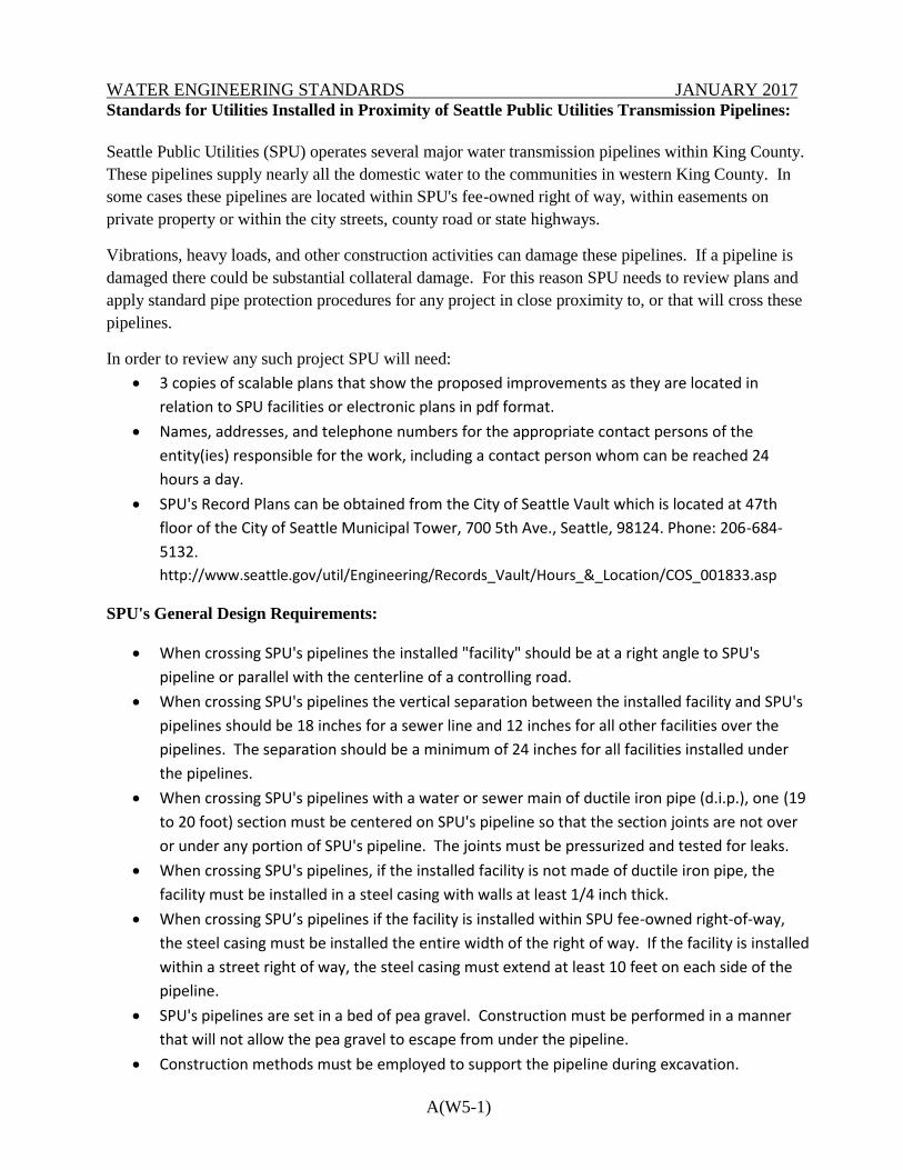
WATER ENGINEERING STANDARDS JANUARY 2017
A(W5-1)
Standards for Utilities Installed in Proximity of Seattle Public Utilities Transmission Pipelines:
Seattle Public Utilities (SPU) operates several major water transmission pipelines within King County.
These pipelines supply nearly all the domestic water to the communities in western King County. In
some cases these pipelines are located within SPU's fee-owned right of way, within easements on
private property or within the city streets, county road or state highways.
Vibrations, heavy loads, and other construction activities can damage these pipelines. If a pipeline is
damaged there could be substantial collateral damage. For this reason SPU needs to review plans and
apply standard pipe protection procedures for any project in close proximity to, or that will cross these
pipelines.
In order to review any such project SPU will need:
3 copies of scalable plans that show the proposed improvements as they are located in
relation to SPU facilities or electronic plans in pdf format.
Names, addresses, and telephone numbers for the appropriate contact persons of the
entity(ies) responsible for the work, including a contact person whom can be reached 24
hours a day.
SPU's Record Plans can be obtained from the City of Seattle Vault which is located at 47th
floor of the City of Seattle Municipal Tower, 700 5th Ave., Seattle, 98124. Phone: 206-684-
5132.
http://www.seattle.gov/util/Engineering/Records_Vault/Hours_&_Location/COS_001833.asp
SPU's General Design Requirements:
When crossing SPU's pipelines the installed "facility" should be at a right angle to SPU's
pipeline or parallel with the centerline of a controlling road.
When crossing SPU's pipelines the vertical separation between the installed facility and SPU's
pipelines should be 18 inches for a sewer line and 12 inches for all other facilities over the
pipelines. The separation should be a minimum of 24 inches for all facilities installed under
the pipelines.
When crossing SPU's pipelines with a water or sewer main of ductile iron pipe (d.i.p.), one (19
to 20 foot) section must be centered on SPU's pipeline so that the section joints are not over
or under any portion of SPU's pipeline. The joints must be pressurized and tested for leaks.
When crossing SPU's pipelines, if the installed facility is not made of ductile iron pipe, the
facility must be installed in a steel casing with walls at least 1/4 inch thick.
When crossing SPU’s pipelines if the facility is installed within SPU fee-owned right-of-way,
the steel casing must be installed the entire width of the right of way. If the facility is installed
within a street right of way, the steel casing must extend at least 10 feet on each side of the
pipeline.
SPU's pipelines are set in a bed of pea gravel. Construction must be performed in a manner
that will not allow the pea gravel to escape from under the pipeline.
Construction methods must be employed to support the pipeline during excavation.
WATER ENGINEERING STANDARDS JANUARY 2017
A(W5-2)
"Trenchless" construction methods must be approved on a site by site basis due to the high
probability of substantial collateral damage if one of SPU's pipelines is damaged.
Cathodic pipe protection methods may be required.
For parallel installations, SPU would like 10 feet of separation on each side of its pipelines.
Shallow curb inlets can be closer than 10 feet if ductile iron is used and the drain line diverts
the water to a catch basin at a remote location.
Special protections or bridging methods may be required to protect the pipeline due to the
width and/or depth of trenching in the vicinity of SPU pipelines.
If SPU's pipeline is exposed, SPU wants to inspect the pipe prior to back filling.
Special fill and/or compaction may be required depending on the method and depth of
excavation.
Overhead wire installations typically require a minimum of 25 feet of vertical clearance from
the ground.
Vibrations could damage some of SPU's pipelines; therefore pile driving, blasting and other
vibration producing work may be restricted.
Heavy loads could damage some of SPU's pipelines. Therefore pipe protection may be
necessary if heavy equipment crosses the pipe. Typical protection would include temporary
bridging using timbers and steel plate.
SPU Operations requirements:
Notify SPU at least 48 hours notice prior to construction. Locating SPU's pipeline by potholing
must be supervised. Call SPU's Lake Youngs Operations at 206-684-3933.
Any work in close proximity to SPU's pipeline (including locating by potholing) must be
supervised by SPU. Call SPU's Lake Youngs Headquarters at 206-684-3933 at least 48 hours in
advance.
Questions:
Teri Hallauer
Sr. Real Property Agent
206-684-5971
Fax: 206-615-1215
Audrey Hansen
Manager, Real Estate Services
206-684-5877
Seattle Public Utilities Real Estate Services
Seattle Municipal Tower
700 Fifth Avenue, Suite 4900
P.O. Box 34018
Seattle, WA 98124-4018
05/01/09