Embed Size (px)
Citation preview
Water Confinement in HydrophobicNanopores. Pressure-InducedWettingand DryingSergei Smirnov,* Ivan Vlassiouk,† Pavel Takmakov,‡ and Fabian Rios
Department of Chemistry and Biochemistry, New Mexico State University, Las Cruces, New Mexico 88003. †Current address: Oak Ridge National laboratory,Oak Ridge, Tennessee 37831. ‡Current address: Department of Chemistry, University of North Carolina at Chapel Hill, Chapel Hill, North Carolina 27599.
Investigation and utilization of hydro-phobic surfaces for various applicationshas gained a new momentum recently.
Hydrophobicity is a fundamental property
that controls interactions between non-
polar substances and water. These interac-
tions in turn are responsible for numerous
physical and biophysical phenomena. Hy-
drophobicity has been studied extensively,
but many aspects are still not well under-
stood. Strong attraction between water
molecules due to hydrogen bonding makes
their interaction with nonpolar substances
unfavorable. Poor wetting of a hydrophobic
surface by water can be observed experi-
mentally as a large contact angle between
a water droplet and the surface.
Recent development of nanometer scale
systems and their applications in the bio-
logical, chemical, and physical sciences in-
creasingly emphasizes the importance of in-
terfaces: the smaller the object size, the
greater its surface-to-volume ratio. What
could have been an insignificant annoy-
ance in the macroscopic and even micro-
scopic systems can no longer be ignored on
the nanoscale. Behavior of a liquid near the
solid surface is substantially different from
that in the bulk and is affected by confine-
ment of liquid in nanosized voids. Water at
a hydrophilic surface was predicted by com-
puter simulation to have a higher density
than in the bulk,1 while near hydrophobic
surfaces, a thin layer of low-density water is
expected.15 Another striking theoretical
prediction is that water confined between
two hydrophobic surfaces or in a hydropho-
bic pore is supposed to spontaneously
evaporate when the size of the pore is suffi-
ciently small.35 Since the phenomenon is
important fundamentally as well as to vari-
ous applications such as electrowetting6
and sensors,7 it is essential to identify theconditions when spontaneous evaporationcan occur.
Similarly to the interior of biologicalmembranes, artificial membranes can bemade hydrophobic and impermeable towater and dissolved in it ions. Moreover,the hydrophobic surface can be also maderesponsive to various stimuli that switch itssurface tension79 and turn the membraneinto an artificial mediator for transport ofions and other species. In living organisms,such transfer across the membrane is selec-tive and controls a variety of metabolicand signaling purposes, such as nerve im-pulses generated by the controlled releaseof ions across the membranes. Mimickingbiological channels using synthetic nano-pores is a challenging scientific problemwith possible applications in medicine, ma-terials science, fuel cells, analytical chemis-try, and sensors. We recently showed thatsuch switching can be initiated by light inthe membrane’s surface of which is modi-fied by a mixed monolayer of hydrophobicmolecules and photochromic spiropyran8 orby pH in hydrophobic membranes withamino or carboxyl groups.10 In order to havea full control of the nanopore wetting, onedesires to have the switching capability in
*Address correspondence [email protected].
Received for review May 17, 2010and accepted July 30, 2010.
Published online August 6, 2010.10.1021/nn101080k
© 2010 American Chemical Society
ABSTRACT Wetting and drying of hydrophobic pores with diameters lower than 0.2 m by aqueous solutions
at different hydrostatic pressures is investigated by measuring the ionic conductance variation through the
nanopores. The critical pressure for water intrusion into the nanopores increases with lowering the pore diameter
and the surface tension of the hydrophobic modification, in agreement with the Laplace equation. Nevertheless,
restoring the pressure to the atmospheric one does not result in spontaneous pore dewetting unless bubbles are
left inside the pores. Such bubbles can appear at the regions of narrowing cross section and/or varying quality of
the hydrophobic modification and thus can be engineered to control water expulsion.
KEYWORDS: hydrophobicity · ionic conductance · nanopores · spontaneousdewetting
ARTIC
LE
www.acsnano.org VOL. 4 NO. 9 5069–5075 2010 5069

both directions, from dry to wet and in reverse. The re-
verse transition is what we address in this paper.
Here we describe the investigation of spontaneous
dewetting in hydrophobic nanoporous membrane fil-
ters using electrical impedance measurements. Under-
standing this phenomenon should provide insight into
the behavior of hydrophobic nanopores and offers
practical implications for utilization of natural and artifi-
cial systems with tailored responsive hydrophobic/
hydrophilic surface properties. We demonstrate that
spontaneous dewetting of hydrophobic nanopores can
occur only when the pores are not completely filled
with water/electrolyte. When monitored electrically, the
effect appears as a significant but incomplete recovery
of the ionic resistance through membrane after dewet-
ting. No recovery of the resistance is observed when the
pores are filled with water completely. The incomplete
recovery is due in part to hysteresis of the surface
conductance.
RESULTS AND DISCUSSIONThe membranes were modified with aliphatic and
fluorinated silanes, as shown in Figure 1 and described
in Materials and Methods, to make them highly hydro-
phobic. An apparent contact angle for a small water
drop (in the sessile technique) is greater than 140° for
all of them. Despite no electrolyte intrusion into the
membrane at ambient external pressure, membranes
have very low but measurable conductance that de-
pends on the modifier and not on the electrolyte con-
centration or its pH.13 Membranes with these hydropho-
bic modifiers show very high resistance, greater than 1
M, and remain superhydrophobic for indistinguish-
ably long time if left in electrolyte. Their resistance var-
ies in the following order: SiH16 SiNH2F8 SiNH9,
which was discussed previously,13 and is due to surface
conductance from ionizable groups below the hydro-
phobic monolayer. Residual hydroxyls on alumina sur-
face and on silanes as well as amines and amides of the
linkers contribute to that surface conductance. Their hy-
dration and the resulting conductance were found to
slightly increase over time, which is also related to hys-
teresis of the contact angle. Autoionization of residual
water bound on the surface contributes to the effect, as
well.
The fact that the resistance is not infinite allows
one to use it for monitoring the extent of water/electro-
lyte intrusion into the pores. In a simple model that we
previously discussed,13 the resistance of a single pore
with constant diameter, D, and length L, is given by
where Rs is the sheet resistance of the hydrophobic
monolayer. If the pore is partially filled with electrolyte,
the resistance of that portion is insignificant (by many
orders of magnitude) as compared to the surface wall
resistance of the “dry” portion. Thus one can still use eq
1 in this case with L referring to the length of the dry
portion.
The equilibrium of forces at a watergas interface
in a nanopore can be described by balancing the pres-
sure difference with the capillary force:
where r1 and r2 are the curvatures of meniscus at the
pore mouth, Pext is the external pressure on the outside
of the membrane, and Pin is the pressure inside the
pore. By virtue of how the cell is prepared in our experi-
ments, Pin always equals the vapor pressure of water,
Pin Pvap (23 Torr at 25 °C). The surface tension differ-
ence, , between the wall/vapor, wv, and wall/liquid,
wl, interfaces relates to the surface tension of the free
liquidvapor interface, , and the contact angle, , on
the surface via the Young equation:
For a hydrophilic surface ( 90°), the equilibrium in
eq 2 cannot be sustained at any external pressure (since
Pext Pvap) and water fills up the pore. For a hydropho-
bic surface ( 90°), the pore remains dry until the ex-
ternal pressure reaches its critical value, which is de-
pendent on and the pore cross section. The latter
can be mimicked as an ellipse with the two diameters,
D1 and D2, which become identical for a perfectly cylin-
drical pore D D1 D2. The critical pressure for
Figure 1. Four types of hydrophobic surface modificationsused in this study with their labels. The first two (SiH16 andSiH2F6) were obtained using toluene solutions of hexadecyl-trimethoxysilane and 1H,1H,2H,2H-perfluoro-octyltrichlorosilane, respectively. The last two (SiNH9 andSiNH2F8) were obtained in two steps: first “amination” us-ing aminopropyl trimethoxysilane in toluene, and then reac-tion with either decanoic acid or fluoroundecanoic acid us-ing EDC coupling reagent in ethanol. For simplicity, Si atomsare drawn connected to the surface via a single SiO bond;the remaining two bonds are presented as hydroxyls, but athigh densities, most neighboring silanes form lateralSiOSi bonds.
Rpore ) RsL
πD(1)
∆P ) Pext - Pin ) -∆γ( 1r1
+ 1r2
) (2)
∆γ ≡ γwv - γwl ) γ cos θ (3)
ART
ICLE
VOL. 4 NO. 9 SMIRNOV ET AL. www.acsnano.org5070

nanometer-sized pores is usually much higher thanthe water vapor pressure, which allows neglecting Pin
in eq 2. The pressure, Po, at which water is capable ofintruding into the pores15
is quite large even for the largest pores in our study. In-deed, for uniform diameter D 0.2 m and hydropho-bic modification of a modest advancing contact angleof a 105° (i.e., || 19 mN/m), the critical pressureis Po 3.8 bar. Simple electrolytes, such as KCl usedhere, have minimal effect on the surface tension. Ac-cording to ref 16, 1.0 M KCl solution has only insignifi-cantly increased from 72 to 74 mN/m. Thus, the out-come of measurements with 1.0 M KCl can bepresumed to hold almost identically to such with purewater.
The pores in the membrane are not identical; theyvary in the quality of coverage (i.e., different ) andthe pore diameter that fluctuates not only between thepores but likely within the pore as well, as is illustratedby Figure 2. From SEM images, “0.2 m” Whatmanmembranes have an average 213 nm diameter on oneside and 114 nm on the other side.11 From the porome-try measurements,11 one side of these membranes haspore diameters, D, ranging from 122 to 256 nm (with143 nm at 50% level) and another side from 130 to 178nm (with 152 nm at 50% level). As a result, the water in-
trusion into the membrane happens not at a singlepressure but over a range of pressures.
Figure 3 demonstrates the variation of the resis-tance as a function of pressure for the two types of com-mercial membranes, 0.2 and 0.02 m, with two typesof hydrophobic surface modifications. Comparison of0.2 m membranes with SiH16 and SiNH2F8 modifica-tions reveals that both demonstrate a broad range ofpressures when water intrudes into the membrane andcauses the resistance to decline. The ratio of the high-est to the lowest pressure is roughly a factor of 2, inagreement with the pore diameter distribution.11 At thesame time, the SiNH2F8-modified membrane requiresalmost twice as much pressure to become totally open,more than 12 bar versus just 7 bar for the SiH16 mem-brane. These values are in a good agreement with thecontact angles on flat surfaces of a 105 and 120° forsurfaces modified with SiH16 and SiNH2F8, respec-tively, and the pore diameter ca. 120 nm is the small-est pore diameter for such membranes.11 Incidentally,the low limit pressures in both cases are roughly halfthe highest value, in agreement with the higher endvalues in the pore diameter distribution (ca. 250 nm).
After reaching the critical pressure, when the mem-brane resistance equals the value corresponding to itbeing filled with electrolyte (ca. 17 ), the resistance re-mains this low even after the pressure is reduced tothe atmospheric one. This is a relatively well-understood situation,5 where spontaneous dewettingof hydrophobically modified nanopores is kineticallyunfeasible despite the significant thermodynamic ad-vantage. A high activation barrier makes such a transi-tion kinetically impossible for the nanopore diametersgreater than D 10 nm. The transition state requiresformation of a bubble inside the pore, which defines alarge activation barrier, #. From the standard capil-lary theory, the latter can be estimated by analyzing thegrand potential variation, , upon creation of a va-por bubble of volume VV that has a surface area SSV incontact with the walls and SLV area of the liquid/vaporinterface:17,18
The two types of transition states, a cylindrically sym-metric annular doughnut-like void and a bubble on thewall, have similar activation barriers that scale approxi-mately as the pore diameter squared, D:17
The dimensional parameter DP/4 is an effectivemeasure of the relative contributions from the surfacetension and the vapor expansion terms. The coefficientsA and B differ for the two cases of transition states anddepend on the contact angle, but both are on the orderof unity (actually, they are less than 117). Equation 6 sug-
Po ≈ ∆Po ) -2γ cos θa( 1D1
+ 1D2
) (4)
Figure 2. Illustration of different pore morphologies in amembrane with hydrophobic modification and their re-sponse to hydrostatic pressure of water (blue) that is insuffi-cient to intrude into pores of a too small diameter (I) butpenetrates through large pores (II). Pores with variable di-ameter (III and IV) have incomplete water penetration. TypeIII has uncontrolled (unintentional) diameter variation, whiletype IV is often realized for alumina membranes that arenot “perfectly open” after their construction using anodiza-tion of Al. Type V represents the geometry of commercial0.02 m membranes from Whatman, where the 0.02 mportion is only 1 m deep on one side of the membrane andits remaining 59 m of thickness has pores with the nomi-nal 0.2 m diameter.11
∆Ω ) VV∆P + SLVγlv + SSV(γsv - γsl) ) VV∆P +
SLVγ + SSVγ cos θ (5)
∆Ω# ≈ πγD2(A + Bδ) (6)
ARTIC
LE
www.acsnano.org VOL. 4 NO. 9 5069–5075 2010 5071

gests that for D 150 nm the activation barrier is ex-tremely high, # 106 kBT, and bubbles cannot spon-taneously form in a reasonable time. Even for D 20nm, the barrier is too high, # 2 104 kBT. Addi-tional contribution to # in eq 5 from line tension thatis proportional to the length of the three phase separa-tion line can somewhat lower17 #, but it would stillbe insufficient to increase the probability of bubble for-mation to a measurable value for the pores of D 10nm.
The situation at intermediate pressures is less obvi-ous. When the applied pressure is restored down tothe atmospheric one, the membrane resistance par-tially recovers. The extent of this recovery is negligiblewith SiH16 modifier (Figure 3A), but it can reach asmuch as 15% with SiNH2F8 (Figure 3B) at pressuresnear 89 bar, which correspond to the maximum inthe pore distribution by diameters (150 nm). Distribu-tion of pore diameters causes water intrusion at differ-ent pressures, and the type of this distribution affectsthe manner in how it proceeds. Uneven pore diameteralso affects the recovery after the external pressuredrops to the atmospheric one. If the pores are perfectcylinders but of different diameters, then they shouldbe entirely filled with water as soon as the critical pres-sure of eq 4 is reached. Large pores are filled first andthe smallest pores last, as illustrated by cases I and II inFigure 2. Pores entirely filled with water do not dry outafter the pressure is dropped back to the atmosphericone due to the above mentioned large activationbarrier.
A pore with variable diameter (such as in the casesIII and IV of Figure 2), say from Dmin to Dmax, may endup at a pressure that exceeds the critical Po for Dmax but
too low for penetrating into the narrowing of Dmin. Theelectrical resistance of the pore at such pressure wouldsignificantly decrease in accordance with a shorter va-por gap but would still be large since the conductancethrough the gap portion is very small. This vapor gaphelps in spontaneous pore dewetting after releasingthe pressure. Water is pushed out of the pore by thesurface tension at the interface with vapor and the wallsas long as the contact angle with the surface staysabove 90°. For high-quality surface modifications, thecontact angle remains almost unaffected by history ofits exposure, but for rough and/or inhomogeneous sur-faces, the hysteresis of the contact angle (the differ-ence between the advancing, a, and receding, r,angles) can be as high as 1015°. For aliphatic surfacemodifiers, it can cause the receding contact angle to fallbelow 90°, that is, when spontaneous dewetting wouldnot be possible for cylindrical pores. The receding con-tact angle for fluorinated surfaces, even with large hys-teresis, remains above 90°, which can explain the differ-ence in behavior of SiNH2F8 and SiH16 0.2 mmembranes. Inhomogeneity of hydrophobic surfacemodification broadens the distribution of critical pres-sures Po and the extent of recovery after the pressurerelease.
Besides the narrowing in the pores, such as in thecase III, other imperfections can also appear duringmembrane preparation. The pores grown by anodiza-tion of metallic Al foil are sealed on one side and needadditional chemical (with phosphoric acid), electro-chemical (changing the anodization voltage at the end),mechanical (polishing), or a combination of such meansto eliminate the oxide barrier on one side, that is, tomake them opened. Depending on the process, the re-
Figure 3. Variation of the impedance at 100 Hz with hydrostatic pressure for commercial 0.2 and 0.02 m membranesmodified with SiNH2F8 and SiH16. Arrows indicate the points when pressure was increased (up) to a designated value inbars and decreased (down) to the atmospheric pressure, respectively. (A) 0.2 m membrane modified with SiH16. Pressuresteps are 0.7 bar starting with 4.3 bar. (B) 0.02 m membrane modified with SiH16. Pressure steps are 0.7 bar (from 2.9 to 8.5bar) and 1.5 bar (from 8.5 to 16.0 bar). Every step of the pressure increase is followed by discharge to the atmospheric pres-sure (0.9 bar). (C,D) 0.2 and 0.02 m membranes modified with SiNH2F8.
ART
ICLE
VOL. 4 NO. 9 SMIRNOV ET AL. www.acsnano.org5072
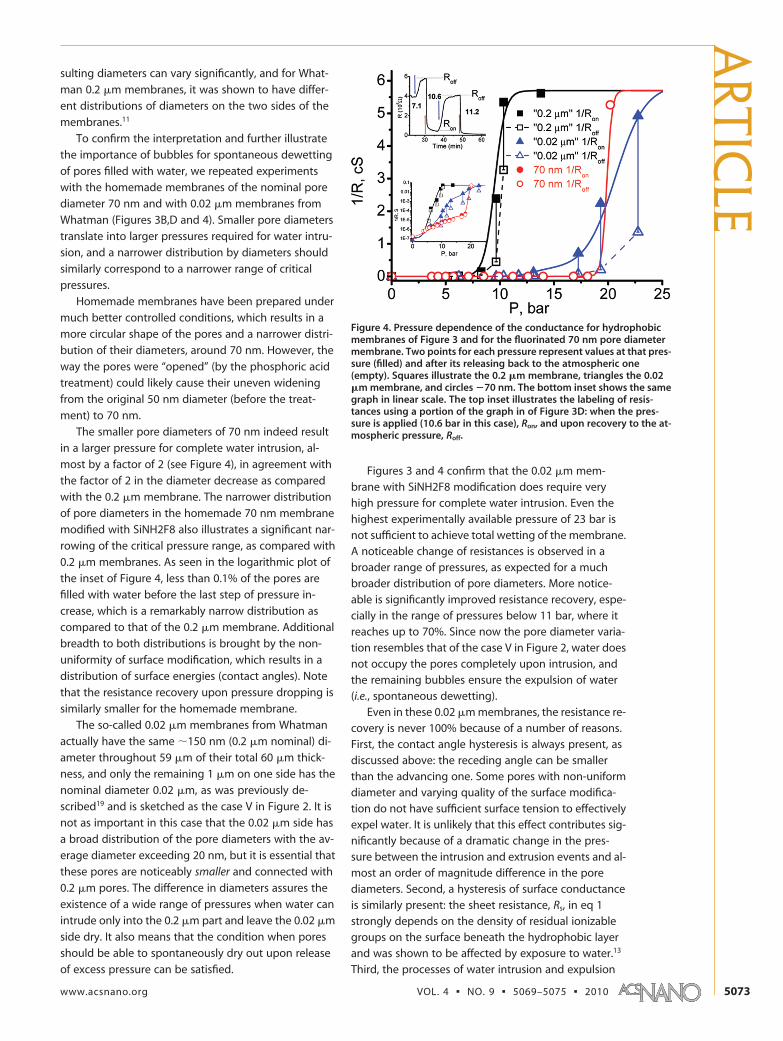
sulting diameters can vary significantly, and for What-
man 0.2 m membranes, it was shown to have differ-
ent distributions of diameters on the two sides of the
membranes.11
To confirm the interpretation and further illustrate
the importance of bubbles for spontaneous dewetting
of pores filled with water, we repeated experiments
with the homemade membranes of the nominal pore
diameter 70 nm and with 0.02 m membranes from
Whatman (Figures 3B,D and 4). Smaller pore diameters
translate into larger pressures required for water intru-
sion, and a narrower distribution by diameters should
similarly correspond to a narrower range of critical
pressures.
Homemade membranes have been prepared under
much better controlled conditions, which results in a
more circular shape of the pores and a narrower distri-
bution of their diameters, around 70 nm. However, the
way the pores were “opened” (by the phosphoric acid
treatment) could likely cause their uneven widening
from the original 50 nm diameter (before the treat-
ment) to 70 nm.
The smaller pore diameters of 70 nm indeed result
in a larger pressure for complete water intrusion, al-
most by a factor of 2 (see Figure 4), in agreement with
the factor of 2 in the diameter decrease as compared
with the 0.2 m membrane. The narrower distribution
of pore diameters in the homemade 70 nm membrane
modified with SiNH2F8 also illustrates a significant nar-
rowing of the critical pressure range, as compared with
0.2 m membranes. As seen in the logarithmic plot of
the inset of Figure 4, less than 0.1% of the pores are
filled with water before the last step of pressure in-
crease, which is a remarkably narrow distribution as
compared to that of the 0.2 m membrane. Additional
breadth to both distributions is brought by the non-
uniformity of surface modification, which results in a
distribution of surface energies (contact angles). Note
that the resistance recovery upon pressure dropping is
similarly smaller for the homemade membrane.
The so-called 0.02 m membranes from Whatman
actually have the same 150 nm (0.2 m nominal) di-
ameter throughout 59 m of their total 60 m thick-
ness, and only the remaining 1 m on one side has the
nominal diameter 0.02 m, as was previously de-
scribed19 and is sketched as the case V in Figure 2. It is
not as important in this case that the 0.02 m side has
a broad distribution of the pore diameters with the av-
erage diameter exceeding 20 nm, but it is essential that
these pores are noticeably smaller and connected with
0.2 m pores. The difference in diameters assures the
existence of a wide range of pressures when water can
intrude only into the 0.2 m part and leave the 0.02 m
side dry. It also means that the condition when pores
should be able to spontaneously dry out upon release
of excess pressure can be satisfied.
Figures 3 and 4 confirm that the 0.02 m mem-brane with SiNH2F8 modification does require veryhigh pressure for complete water intrusion. Even thehighest experimentally available pressure of 23 bar isnot sufficient to achieve total wetting of the membrane.A noticeable change of resistances is observed in abroader range of pressures, as expected for a muchbroader distribution of pore diameters. More notice-able is significantly improved resistance recovery, espe-cially in the range of pressures below 11 bar, where itreaches up to 70%. Since now the pore diameter varia-tion resembles that of the case V in Figure 2, water doesnot occupy the pores completely upon intrusion, andthe remaining bubbles ensure the expulsion of water(i.e., spontaneous dewetting).
Even in these 0.02 m membranes, the resistance re-covery is never 100% because of a number of reasons.First, the contact angle hysteresis is always present, asdiscussed above: the receding angle can be smallerthan the advancing one. Some pores with non-uniformdiameter and varying quality of the surface modifica-tion do not have sufficient surface tension to effectivelyexpel water. It is unlikely that this effect contributes sig-nificantly because of a dramatic change in the pres-sure between the intrusion and extrusion events and al-most an order of magnitude difference in the porediameters. Second, a hysteresis of surface conductanceis similarly present: the sheet resistance, Rs, in eq 1strongly depends on the density of residual ionizablegroups on the surface beneath the hydrophobic layerand was shown to be affected by exposure to water.13
Third, the processes of water intrusion and expulsion
Figure 4. Pressure dependence of the conductance for hydrophobicmembranes of Figure 3 and for the fluorinated 70 nm pore diametermembrane. Two points for each pressure represent values at that pres-sure (filled) and after its releasing back to the atmospheric one(empty). Squares illustrate the 0.2 m membrane, triangles the 0.02m membrane, and circles 70 nm. The bottom inset shows the samegraph in linear scale. The top inset illustrates the labeling of resis-tances using a portion of the graph in of Figure 3D: when the pres-sure is applied (10.6 bar in this case), Ron, and upon recovery to the at-mospheric pressure, Roff.
ARTIC
LE
www.acsnano.org VOL. 4 NO. 9 5069–5075 2010 5073

are not isothermal under our experimental conditions.
The membrane resistance in both processes ap-
proaches a saturation value very slowly (Figure 3). Wa-
ter intrusion is an exothermal process because of the
work done against the surface tension and condensa-
tion of excess water vapor, but more significantly, pres-
surization of the vessel by gas is also increasing temper-
ature in the chamber. The temperature change needs
a significant time to equilibrate with surroundings,
which would be seen as a slow component in the resis-
tance decline following the initial sharp drop. The dura-
tion of this slow component obviously depends on the
change in temperature and the geometry of the cell
and the pressurizing chamber. Similarly, the dewetting
process is endothermic and is accompanied by the local
temperature decline, but the temperature drop due to
the nitrogen gas expulsion from the pressure chamber
leads to a stronger cooling. As a result, the resistance re-
covery via warming up is slow, as well.
Phenomena similar to those of spontaneous dewet-
ting discussed here are also of importance in design-
ing superhydrophobic/oleophobic surfaces. Combina-
tion of the effects of microscopic pockets of air trapped
beneath the liquid droplets and the texture of spe-
cially engineered surfaces can provide high contact
angles with low hysteresis for liquids with greatly vary-ing surface tension.20,21 In such engineered textures, it issimilarly important to have incomplete surface wettingto efficiently support metastable compositesolidliquidair interfaces.
CONCLUSIONSWe experimentally confirm that long hydrophobic
nanopores allow water intrusion under a sufficientlyhigh hydrostatic pressure, the critical value of which de-pends on the pore diameter and the type/quality ofthe hydrophobic modification. At the same time, restor-ing the pressure to the atmospheric one results in spon-taneous dewetting only when a bubble of vapor is leftinside the pore. Such bubbles appear at the regions ofnarrowing cross section and/or varying quality of thehydrophobic modification and thus can be engineeredto control water expulsion. The ionic resistance throughthe membranes correspondingly demonstrates dra-matic changes accompanying these events of electro-lyte entering and leaving the pores. The total resistancechange spans in excess of 6 orders of magnitude. Re-covery of the resistance to the original high value is al-ways less than 100%, which, in addition to the men-tioned effects, is due to hysteresis in the conductanceof hydrophobic walls after wetting and drying.
MATERIALS AND METHODSAll chemicals used in this work were obtained from Sigma-
Aldrich (St Louis, MO) and were used as received.Three types of free-standing nanoporous alumina mem-
branes were used in this study: commercial “Anodisc” fromWhatman (Whatman, Florham Park, NJ) with the nominal 0.2 or0.02 m diameter pores (60 m thick)1114 and the homemade60 m thick membranes with 70 nm diameter pores. The latterwere prepared using a previously described procedure14 thatconsists of anodization of cleaned and electropolished Al foil(99.9%, Alfa Aesar, Ward Hill, MA) in oxalic acid at 5 °C and 40 Vfollowed by dissolution of Al substrate in CuCl2 and pore open-ing/widening in 1 M phosphoric acid at room temperature for 30min. The membranes were rendered highly hydrophobic usingfour different modifications (shown in Figure 1), as previously de-scribed.13 In the first scheme, the membrane surface was di-rectly silanized with hexadecyltriethoxysilane from toluene solu-tion (overnight); in the second scheme, the membrane surfacewas also directly silanized with 1H,1H,2H,2H-perfluorooctyltrichlorosilane from toluene solution, also over-night. We will label such membranes as SiH16 and SiH2F6, re-spectively (see Figure 1). In both cases, the treatment was con-cluded by thorough washing in ethanol and overnight baking at120 °C. In the other two schemes, the membrane was first ami-nated using 3-aminopropyl trimethoxysilane and then carboxy-lic acid ends of either decanoic acid or 2H,2H,3H,3H-perfluoroundecanoic acid were coupled to the surface-boundamino groups using EDC coupling reagent 1-ethyl-3-(3-(dimethylamino)propyl)carbodiimide.13 We will label such mem-branes as SiNH9 and SiNH2F8, respectively (see Figure 1). Thedensity of bound to the membrane surface monolayers wasmonitored by IR absorbance. The data will be presented onlyfor SiH16 and SiNH2F8 modifications because others showed in-ferior electrical resistance properties compared to these two.13
The electrical impedance due to ionic conductance throughthe membranes was measured in a homemade two-electrodeelectrochemical cell13 using a CH 604B electrochemical worksta-
tion (from CH Instruments Inc., Austin, TX). The membrane formsa barrier between the two halves of the cell containing de-gassed 1.0 M potassium chloride in water at pH 7. Two Ag/AgClelectrodes were in close proximity to the membrane, and a lowvoltage (5 mV) was employed for AC impedance measurements.The open area of the membranes was 0.25 cm2 that resulted inthe resistance of 17 with unmodified membrane in 1.0 M KCl;that is, this is the minimum measurable resistance or the “cell re-sistance” under the experimental conditions. The impedancevariation with pressure was monitored at 100 Hz. At this fre-quency, the capacitive contribution to the impedance is mini-mal. In order to maintain reproducible environment, the cell wasfirst degassed using a water pump and a similarly degassed so-lution was introduced independently into the both cell compart-ments by suction. Two 1/8 in. o.d. Tygon tubes were left con-nected to each side of the cell and filled with electrolyte up tothe length of 50 cm. Since gas diffusion through such a long dis-tance is incredibly slow, applying pressure to this assemblyhydrostatically with a gas precludes its penetration into themembrane, leaving only electrolyte and water vapor. This assem-bly was placed inside a homemade stainless steel high-pressurechamber with electrical feed-through contacts for connectingthe electrodes to the workstation. The pressure inside the cham-ber was supplied by nitrogen gas from a tank connected via ahigh-pressure manometer. The maximum controlled pressurewas limited by the pressure reductor not to exceed 23 bar abovethe atmospheric one.
Acknowledgment. This work was partially supported by agrant from the National Science Foundation (NSF DMR 0900238).The authors are also grateful to NM EPSCOR program for provid-ing funds to purchase the potentiostat used in this study.
REFERENCES AND NOTES1. Lum, K.; Chandler, D.; Weeks, J. Hydrophobicity at Small
and Large Length Scales. J. Phys. Chem. B 1999, 103, 4570–4577.
ART
ICLE
VOL. 4 NO. 9 SMIRNOV ET AL. www.acsnano.org5074
2. Helmy, R.; Kazakevich, Y.; Ni, C.; Fadeev, A. Wetting inHydrophobic Nanochannels: A Challenge of ClassicalCapillarity. J. Am. Chem. Soc. 2005, 127, 12446–12447.
3. Lum, K.; Chandler, D. Phase Diagram and Free Energies ofVapor Films and Tubes for a Confined Fluid. Int. J.Thermophys. 1998, 19, 845–855.
4. Lum, K; Luzar, A. Pathway to Surface-Induced PhaseTransition of a Confined Fluid. Phys. Rev. E 1997, 56,R6283–R6286.
5. Luzar, A. Activation Barrier Scaling for the SpontaneousEvaporation of Confined Water. J. Phys. Chem. B 2004, 108,19859–19866.
6. Krupenkin, T. N.; Taylor, J. A.; Schneider, T. M.; Yang, S.From Rolling Ball to Complete Wetting: The DynamicTuning of Liquids on Nanostructured Surfaces. Langmuir2004, 20, 3824–3827.
7. Vlassiouk, I.; Smirnov, S. Biosensing with Nanopores. InBiosensing Using Nanomaterials; Merkoci, A., Ed.; Wiley:New York, 2009; pp 459490.
8. Vlassiouk, I.; Park, C.-D.; Vail, S. A.; Gust, D.; Smirnov, S.Control of Nanopore Wetting by a PhotochromicSpiropyran: A Light-Controlled Valve and Electrical Switch.Nano Lett. 2006, 6, 1013–1017.
9. Rios, F.; Smirnov, S. Biochemically Responsive SmartSurface. ACS Appl. Mater. Interfaces 2009, 1, 768–774.
10. Holmes-Farley, S. R.; Reamey, R. H.; McCarthy, T. J.; Deutch,J.; Whitesides, G. M. AcidBase Behavior of CarboxylicAcid Groups Covalently Attached at the Surface ofPolyethylene: The Usefulness of Contact Angle inFollowing the Ionization of Surface Functionality.Langmuir 1985, 1, 725–740.
11. Hernandez, A.; Martinez, F.; Martin, A.; Pradanos, P. PorousStructure and Surface Charge Density on the Walls ofMicroporous Alumina Membranes. J. Colloid Interface Sci.1995, 173, 284–296.
12. Vlassiouk, I.; Krasnoslobodtsev, A.; Smirnov, S.; Germann,M. ‘Direct’ Detection and Separation of DNA UsingNanoporous Alumina Filters. Langmuir 2004, 20,9913–9915.
13. Smirnov, S.; Vlassiouk, I.; Rios, F.; Vail, S.; Gust, D. ElectricalConductance of Hydrophobic Membranes or WhatHappens Below the Surface. Langmuir 2007, 23,7784–7792.
14. Takmakov, P.; Vlassiouk, I.; Smirnov, S. Application ofAnodized Aluminum in Fluorescence Detection ofBiological Species. Anal. Bioanal. Chem. 2006, 385,954–958.
15. Washburn, E. W. The Dynamics of Capillary Flow. Phys. Rev.1921, 17, 273–283.
16. Yu, Y. X.; Gao, G. H.; Li, Y. G. Surface Tension for AqueousElectrolyte Solutions by the Modified Mean SphericalApproximation. Fluid Phase Equilib. 2000, 173, 23–38.
17. Lefevre, B.; Saugey, A.; Barrat, J. L.; Bocquet, L.; Charlaix, E.;Gobin, P. F.; Vigier, G. Intrusion and Extrusion of Water inHydrophobic Mesopores. J. Chem. Phys. 2004, 120,4927–4938.
18. Husowitz, B.; Talanquer, V. Nucleation in CylindricalCapillaries. J. Chem. Phys. 2004, 121, 8021–8028.
19. Vlassiouk, I.; Takmakov, P.; Smirnov, S. Sensing DNAHybridization via Ionic Conductance through aNanoporous Electrode. Langmuir 2005, 21, 4776–4778.
20. Tuteja, A.; Choi, W.; Mabry, J.; McKinley, G.; Cohen, R.Robust Omniphobic Surfaces. Proc. Natl. Acad. Sci. U.S.A.2008, 105, 18200–18205.
21. Tuteja, A.; Choi, W.; Ma, M.; Mabry, J.; Mazzella, S.;Rutledge, G.; McKinley, G.; Cohen, R. DesigningSuperoleophobic Surfaces. Science 2007, 318, 1618–1622.
ARTIC
LE
www.acsnano.org VOL. 4 NO. 9 5069–5075 2010 5075