Embed Size (px)
Citation preview
1
Wastewater Treatment Systems
Biological Wastewater Treatment
Biological Treatment Systems
Attached Growth Systems Trickling Filter Rotating Biological Contactor
Suspended Growth System Activated Sludge System
2
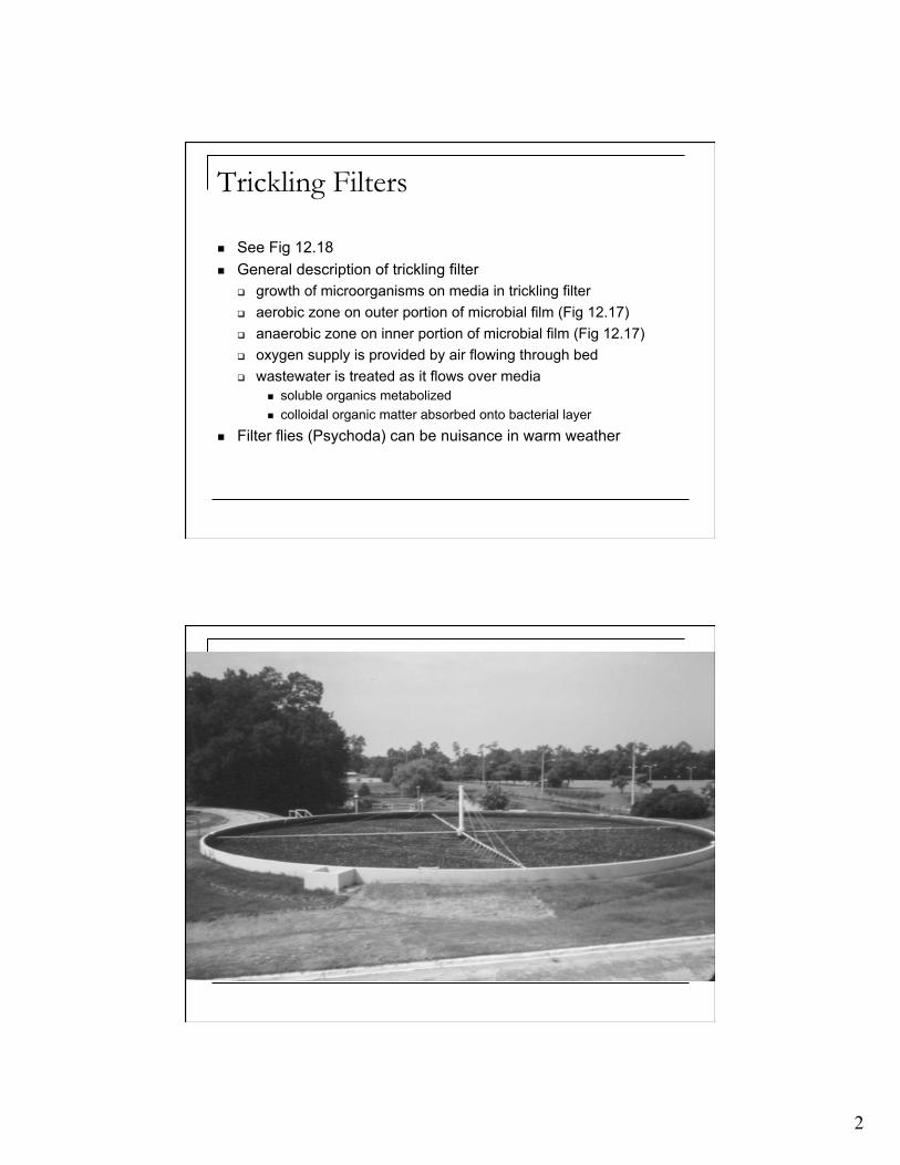
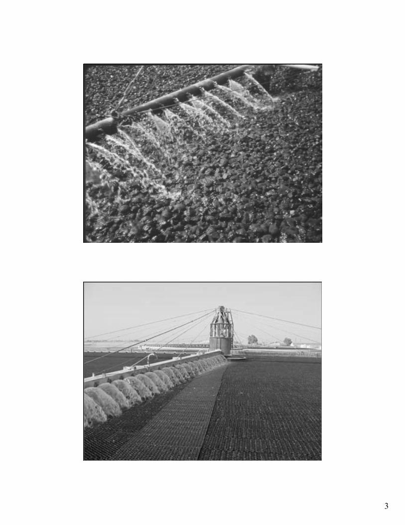
Trickling Filters
See Fig 12.18 General description of trickling filter
growth of microorganisms on media in trickling filter aerobic zone on outer portion of microbial film (Fig 12.17) anaerobic zone on inner portion of microbial film (Fig 12.17) oxygen supply is provided by air flowing through bed wastewater is treated as it flows over media
soluble organics metabolized colloidal organic matter absorbed onto bacterial layer
Filter flies (Psychoda) can be nuisance in warm weather
3

4
Trickling Filter Secondary Treatment Systems As microorganisms grow, the microbial growth sloughs off the
media Microbial solids are captured in a final clarifier Recirculation
dilutes raw wastewater and reduces wastewater strength wastewater passes through trickling filter more than once maintains a minimum hydraulic loading on filter common range for QR/Q: 0.5 - 3.0 see other recirculation patterns (Fig 12.22, Fig. 12.23)
5
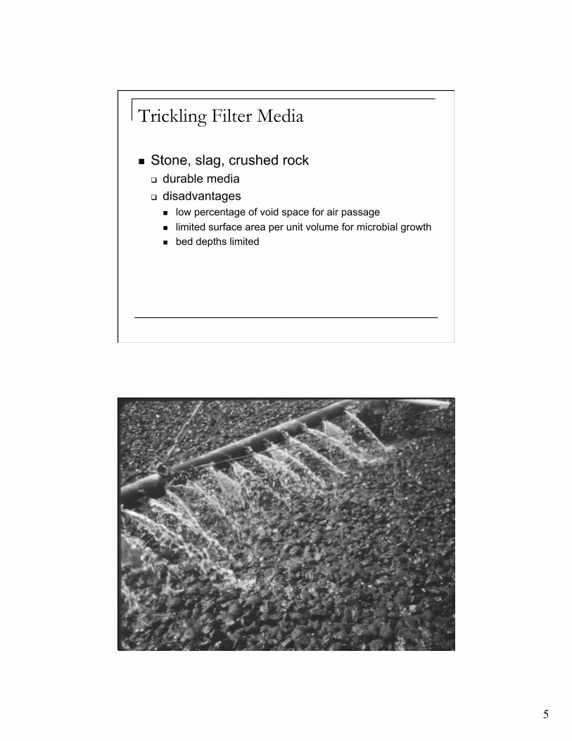
Trickling Filter Media
Stone, slag, crushed rock durable media disadvantages
low percentage of void space for air passage limited surface area per unit volume for microbial growth bed depths limited
6
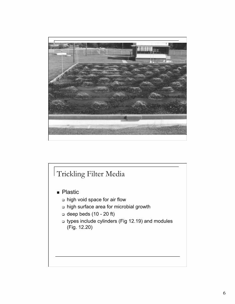
Trickling Filter Media
Plastic high void space for air flow high surface area for microbial growth deep beds (10 - 20 ft) types include cylinders (Fig 12.19) and modules
(Fig. 12.20)
7
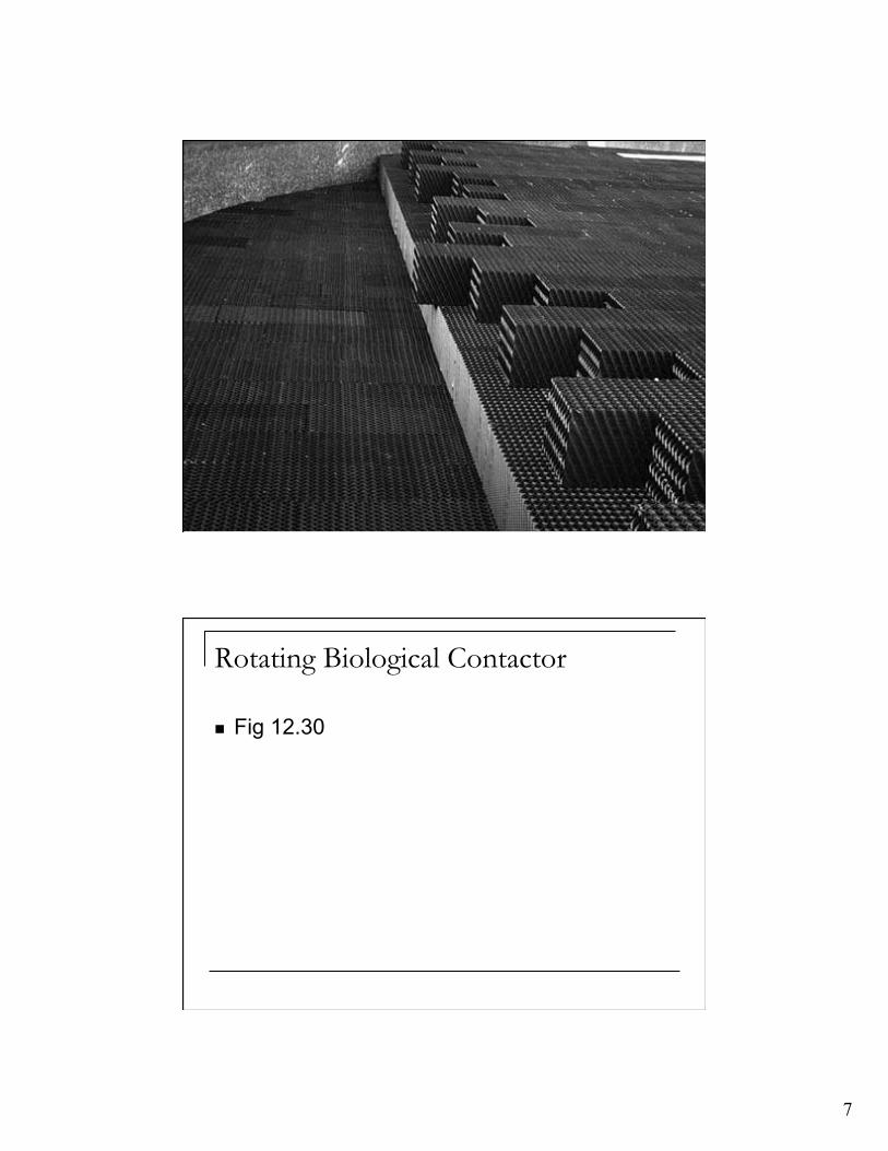
Rotating Biological Contactor
Fig 12.30

8
9
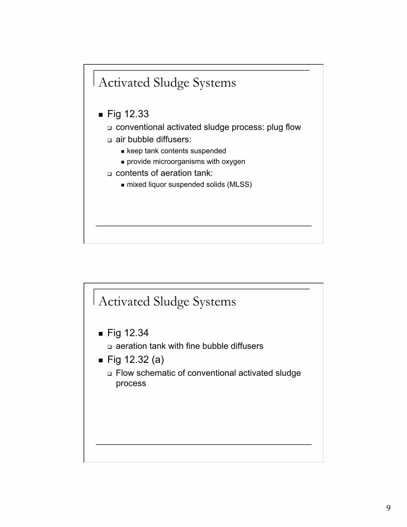
Activated Sludge Systems
Fig 12.33 conventional activated sludge process: plug flow air bubble diffusers:
keep tank contents suspended provide microorganisms with oxygen
contents of aeration tank: mixed liquor suspended solids (MLSS)
Activated Sludge Systems
Fig 12.34 aeration tank with fine bubble diffusers
Fig 12.32 (a) Flow schematic of conventional activated sludge
process

10
Description of Activated Sludge
Wastewater flows into aerated tank Microorganisms metabolize organic substrate Biological flocs of microorganisms (activated
sludge) settle out in secondary clarifier
Description of Activated Sludge
Settled microorganisms are recycled to the aeration tank
Clear supernatant from the secondary clarifier can be disinfected and discharged from the plant if no additional treatment is required

11
Description of Activated Sludge
When organic substrate is utilized in the synthesis of new cellular material, microbial mass accumulates in the system
The excess microbial mass (sludge) is wasted from the system
The sludge wasted from the system is treated in the sludge processing units of the plant before returning to the environment
Activated Sludge Systems Problems Treatment Efficiency - Example 1 Activated Sludge Mass Balance - Example 1
12
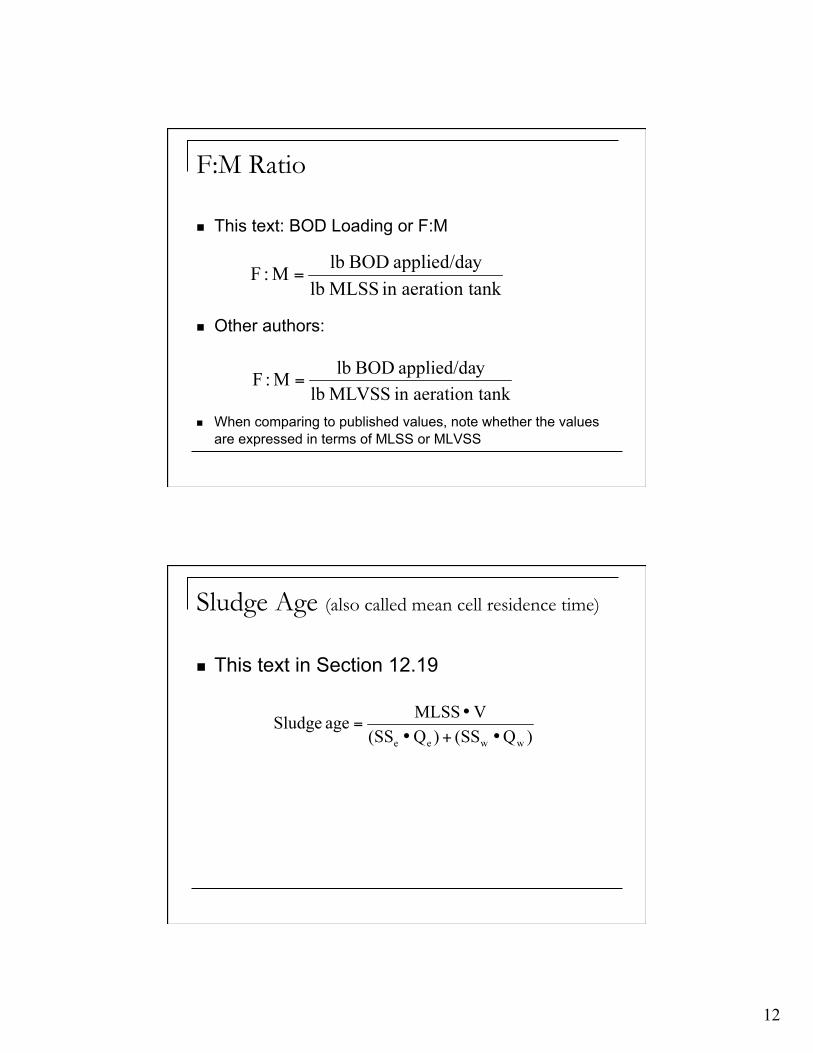
F:M Ratio
This text: BOD Loading or F:M
Other authors:
When comparing to published values, note whether the values are expressed in terms of MLSS or MLVSS
Sludge Age (also called mean cell residence time)
This text in Section 12.19
13
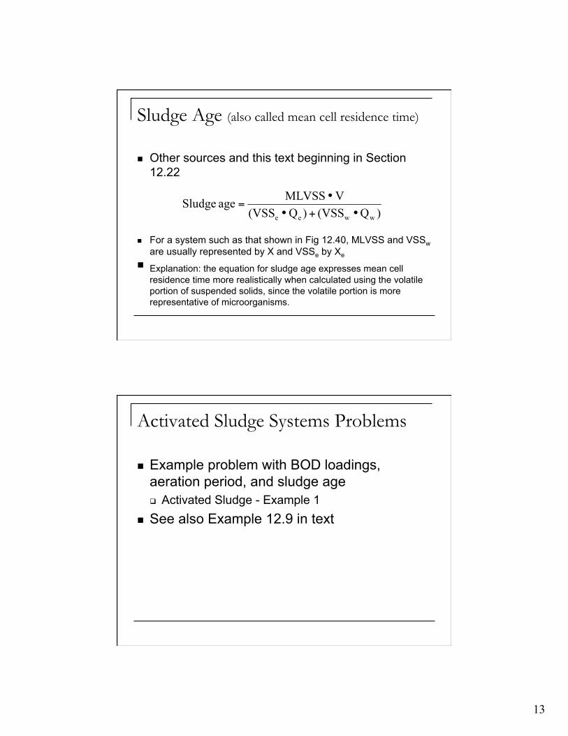
Sludge Age (also called mean cell residence time)
Other sources and this text beginning in Section 12.22
For a system such as that shown in Fig 12.40, MLVSS and VSSw are usually represented by X and VSSe by Xe
Explanation: the equation for sludge age expresses mean cell residence time more realistically when calculated using the volatile portion of suspended solids, since the volatile portion is more representative of microorganisms.
Activated Sludge Systems Problems
Example problem with BOD loadings, aeration period, and sludge age Activated Sludge - Example 1
See also Example 12.9 in text
14
Activated Sludge Processes Conventional activated sludge process
plug flow: Fig 12.32(a)
Step-aeration activated sludge process also called “step-feed” influent wastewater introduced at several points helps
provide a more uniform oxygen demand throughout the flow path
Fig 12.32(b)
Completely-mixed activated sludge process Fig 12.40
Activated Sludge Processes: Extended Aeration Extended aeration activated sludge process
Fig 12.32(d): note that there is no primary clarifier residential communities, small towns, etc. aeration period: 24 hours or longer operates in endogenous growth phase final clarifiers
long detention time overflow rate: 200 - 600 gpd/ft2

15
Activated Sludge Processes: Extended Aeration Types of extended aeration systems
oxidation ditch (Fig 12.36) Carrousel® system (Fig 12.37) field erected plant (Fig 12.35)
Design of Activated Sludge Systems Using an approach that relies on data such as that
presented in Table 12.3 and/or state standards Using a kinetics model, as presented in Section
12.22, assuming certain wastewater characteristics Using kinetic constants determined in a laboratory or
pilot plant study as described in Section 12.23

16
Design of Activated Sludge Systems Design of Step Aeration System
Activated Sludge - Example 2 see also Example 12.10, text
Design of Extended Aeration System Activated Sludge - Example 3 see also Example 12.12
Design of Activated Sludge Systems Design of a completely-mixed activated
sludge process using kinetics approach Example 12.15, text