Embed Size (px)
Citation preview

Benjamin FollettStructural OptionArchitectural Engineering Senior Thesis Presentation 2009The Pennsylvania State University
Washington Park CondominiumsMt. Lebanon, Pennsylvania
Project Overview
Existing Structure
Why Re‐design?
Structural Redesign
Architectural Detailing
Conclusion
Acoustics
Presentation Outline
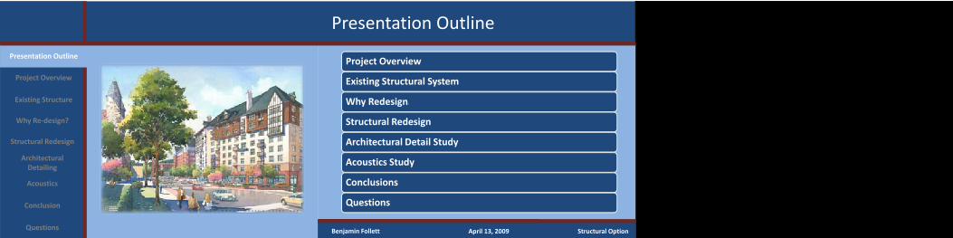
Project Overview
Existing Structural System
Why Redesign?
Structural Redesign
Architectural Detail Study
Acoustics Study
Conclusions
Questions
Presentation Outline
Questions Benjamin Follett April 13, 2009 Structural Option
Project Overview
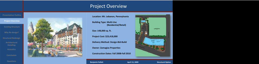
Location: Mt. Lebanon, Pennsylvania
Building Type: Multi‐Use (Residential/Retail)
Size: 148,000 sq. ft.
Project Cost: $23,418,000
Delivery Method: Design‐Bid‐Build
Owner: Zamagias Properties
Construction Dates: Fall 2008‐Fall 2010
Project Overview
Existing Structure
Why Re‐design?
Structural Redesign
Architectural Detailing
Conclusion
Acoustics
Questions
Presentation Outline
Benjamin Follett April 13, 2009 Structural Option
Existing Conditions – Floor Systems
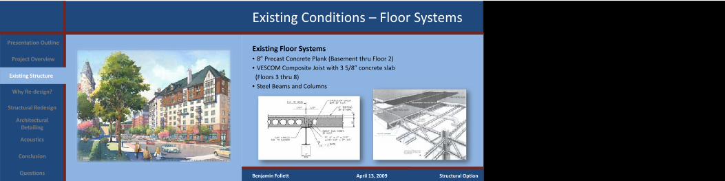
Existing Floor Systems• 8” Precast Concrete Plank (Basement thru Floor 2)• VESCOM Composite Joist with 3 5/8” concrete slab (Floors 3 thru 8)
• Steel Beams and Columns
Project Overview
Existing Structure
Why Re‐design?
Structural Redesign
Architectural Detailing
Conclusion
Acoustics
Questions
Presentation Outline
Benjamin Follett April 13, 2009 Structural Option
Existing Conditions – Lateral System
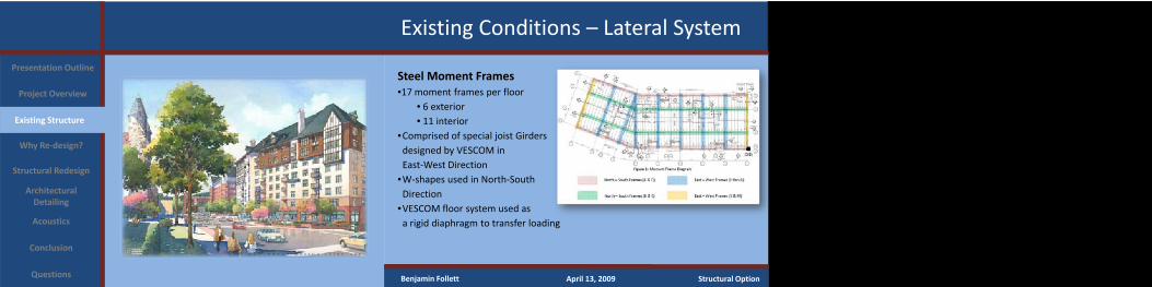
Steel Moment Frames•17 moment frames per floor
• 6 exterior• 11 interior
•Comprised of special joist Girders designed by VESCOM inEast‐West Direction
Project Overview
Existing Structure
Why Re‐design?
Structural Redesign
Architectural Detailing
Conclusion
Acoustics
Questions
Presentation Outline
Benjamin Follett April 13, 2009 Structural Option
•W‐shapes used in North‐South Direction
•VESCOM floor system used as a rigid diaphragm to transfer loading
Existing Conditions – Lateral System
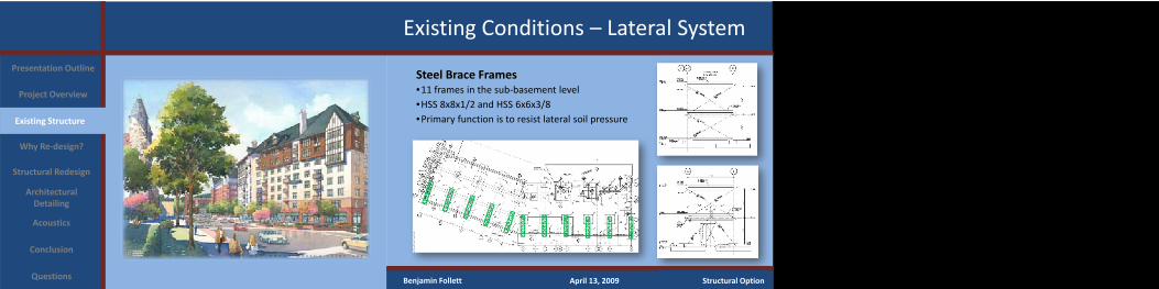
Steel Brace Frames•11 frames in the sub‐basement level•HSS 8x8x1/2 and HSS 6x6x3/8•Primary function is to resist lateral soil pressure
Project Overview
Existing Structure
Why Re‐design?
Structural Redesign
Architectural Detailing
Conclusion
Acoustics
Questions
Presentation Outline
Benjamin Follett April 13, 2009 Structural Option
Why Redesign?
Project Overview
Existing Structure
Why Re‐design?
Structural Redesign
Architectural Detailing
Conclusion
Acoustics
Questions
Presentation Outline
Benjamin Follett April 13, 2009 Structural Option
Problem Statement•Lack of construction experience with newer composite steel joist system• Inefficient lateral system with most columns and beams being part of the moment frame system
•Possibility of unwanted floor vibrations with use of composite joist system.•Ultimately why was composite joist system chosen over a reinforced concrete system?
Problem Solution – Complete redesign of both the gravity and lateral systems of Washington Park Condominiums
Why Redesign?
Project Overview
Existing Structure
Why Re‐design?
Structural Redesign
Architectural Detailing
Conclusion
Acoustics
Questions
Presentation Outline
Benjamin Follett April 13, 2009 Structural Option
Design Goals•Study and determine relevant differences between the use of steel and concrete structures for Washington Park Condominiums
•Maintain allowable story drift while reducing motion perceived by building occupants
•Adhere to the current column layout of the building•Design a more efficient lateral force resisting system using concrete•Reduce sound transmission throughout building between areas with high noise levels and the apartments
Learn how to design both gravity and lateral systems using reinforced concrete.
Structural Redesign – Gravity System
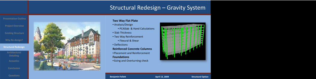
Two Way Flat Plate• Analysis/Design
• PCASlab & Hand Calculations• Slab Thickness• Two Way Reinforcement
• Flexural & Shear• DeflectionsReinforced Concrete Columns•Placement and ReinforcementFoundations•Sizing and Overturning check
Project Overview
Existing Structure
Why Re‐design?
Structural Redesign
Architectural Detailing
Conclusion
Acoustics
Questions
Presentation Outline
Benjamin Follett April 13, 2009 Structural Option
Structural Redesign – Gravity System
Project Overview
Existing Structure
Why Re‐design?
Structural Redesign
Architectural Detailing
Conclusion
Acoustics
Questions
Presentation Outline
Benjamin Follett April 13, 2009 Structural Option
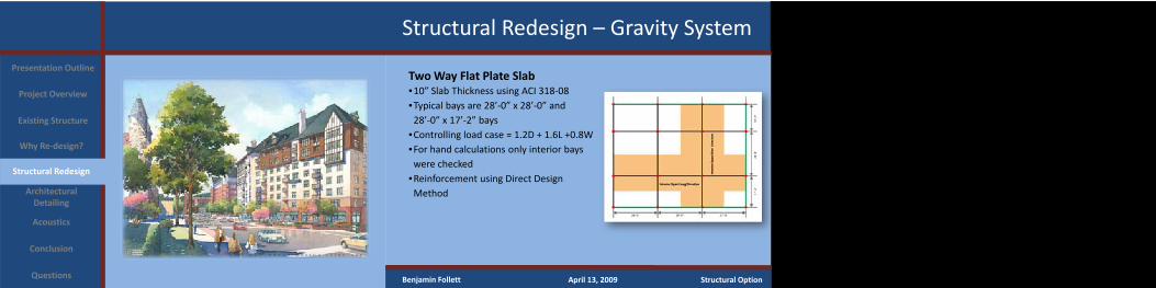
Two Way Flat Plate Slab•10” Slab Thickness using ACI 318‐08•Typical bays are 28’‐0” x 28’‐0” and 28’‐0” x 17’‐2” bays
•Controlling load case = 1.2D + 1.6L +0.8W•For hand calculations only interior bays were checked
•Reinforcement using Direct Design Method
Structural Redesign – Gravity System
Two Way Flat Plate SlabProject Overview
Existing Structure
Why Re‐design?
Structural Redesign
Architectural Detailing
Conclusion
Acoustics
Questions
Presentation Outline
Benjamin Follett April 13, 2009 Structural Option
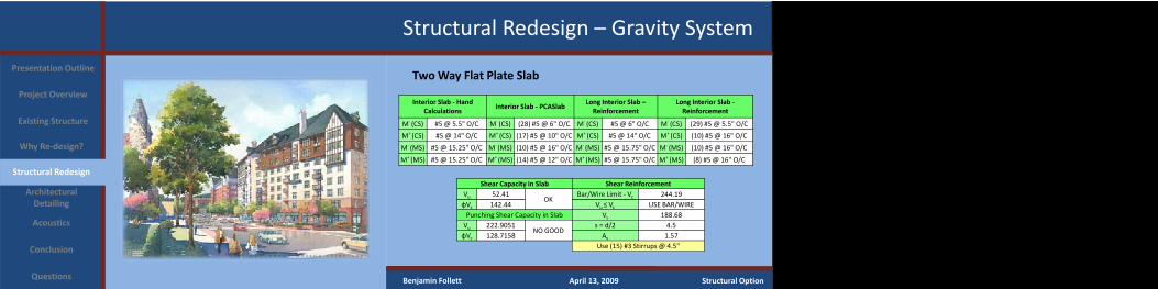
Interior Slab ‐ Hand Calculations
Interior Slab ‐ PCASlabLong Interior Slab –Reinforcement
Long Interior Slab ‐Reinforcement
M‐ (CS) #5 @ 5.5" O/C M‐ (CS) (28) #5 @ 6" O/C M‐ (CS) #5 @ 6" O/C M‐ (CS) (29) #5 @ 5.5" O/C
M+ (CS) #5 @ 14" O/C M+ (CS) (17) #5 @ 10" O/C M+ (CS) #5 @ 14" O/C M+ (CS) (10) #5 @ 16" O/C
M‐ (MS) #5 @ 15.25" O/C M‐ (MS) (10) #5 @ 16" O/C M‐ (MS) #5 @ 15.75" O/C M‐ (MS) (10) #5 @ 16" O/C
M+ (MS) #5 @ 15.25" O/C M+ (MS) (14) #5 @ 12" O/C M+ (MS) #5 @ 15.75" O/C M+ (MS) (8) #5 @ 16" O/C
Shear Capacity in Slab Shear ReinforcementVu 52.41
OKBar/Wire Limit ‐ Vc 244.19
φVc 142.44 Vu ≤ Vc USE BAR/WIREPunching Shear Capacity in Slab Vs 188.68Vu 222.9051
NO GOODs = d/2 4.5
φVc 128.7158 Av 1.57Use (15) #3 Stirrups @ 4.5"
Structural Redesign – Gravity System
Two Way Flat Plate SlabProject Overview
Existing Structure
Why Re‐design?
Structural Redesign
Architectural Detailing
Conclusion
Acoustics
Questions
Presentation Outline
Benjamin Follett April 13, 2009 Structural Option

Structural Redesign – Gravity System
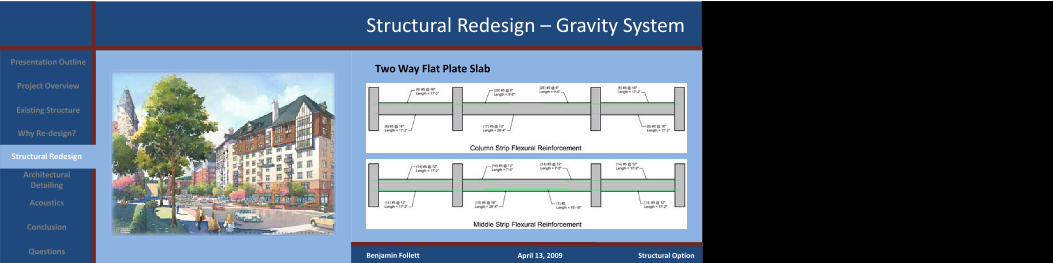
Two Way Flat Plate Slab – Deflections•Allowable deflections from ACI 9.5•All slab deflections meet given criteria
Project Overview
Existing Structure
Why Re‐design?
Structural Redesign
Architectural Detailing
Conclusion
Acoustics
Questions
Presentation Outline
Benjamin Follett April 13, 2009 Structural Option
Deflections for Two Way Slabs
Interior Span (Short Direction)
Exterior Span (Short Direction)
Interior Span (Long Direction)
Exterior Span (Long Direction)
Allowable Live Load Deflection
l/360 = 0.944 in l/360 = 0.944 in l/360 = 0.933 in l/360 = 0.944 in
Actual Live Load Deflection
0.111 in 0.139 in 0.149 in 0.118 in
Allowable Total Load Deflection
l/240 = 1.417 in l/240 = 1.417 in l/240 = 1.417 in l/240 = 1.417 in
Actual Total Load Deflection
0.326 in 0.412 in 0.421 in 0.353 in
Structural Redesign – Gravity System
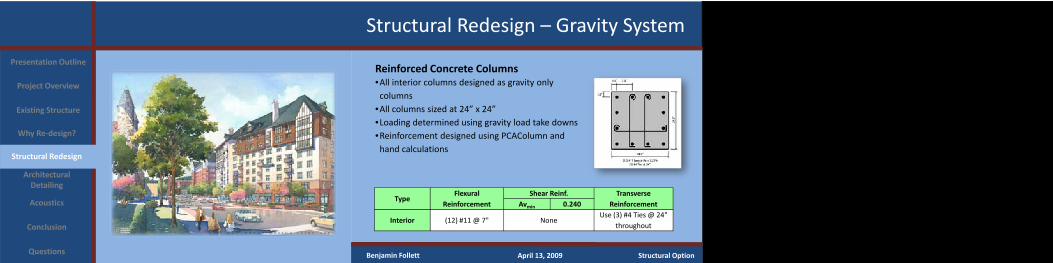
Reinforced Concrete Columns•All interior columns designed as gravity only columns
•All columns sized at 24” x 24”•Loading determined using gravity load take downs•Reinforcement designed using PCAColumn and hand calculations
TypeFlexural
ReinforcementShear Reinf. Transverse
ReinforcementAvmin 0.240
Interior (12) #11 @ 7" NoneUse (3) #4 Ties @ 24"
throughout
Project Overview
Existing Structure
Why Re‐design?
Structural Redesign
Architectural Detailing
Conclusion
Acoustics
Questions
Presentation Outline
Benjamin Follett April 13, 2009 Structural Option
Structural Redesign – Foundations
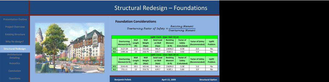
Foundation ConsiderationsProject Overview
Existing Structure
Why Re‐design?
Structural Redesign
Architectural Detailing
Conclusion
Acoustics
Questions
Presentation Outline
Uplift Check ‐ Shear Wall (Wind)
Overturning Moment (k‐ft)
Wall Length (ft)
Wall Weight (kips)
Axial Load on Wall (kips)
Resisting Moment (k‐ft)
Factor of Safety
(Calculated)
Factor of Safety (Recommended)
Uplift Problem
ST2 3127.59 19.5 422.66 981.9 13694.0 4.38 3.0 NoSL2 1385.26 10 216.75 619.7 4182.1 3.02 3.0 No
Uplift Check ‐ Shear Wall (Wind)
Overturning Moment (k‐ft)
Wall Length (ft)
Wall Weight (kips)
Axial Load on Wall (kips)
Resisting Moment (k‐ft)
Factor of Safety
(Calculated)
Factor of Safety (Recommended)
Uplift Problem
ST2 2543.45 19.5 422.66 981.9 13694.0 5.38 3.0 NoSL2 715.11 10 216.75 619.7 4182.1 5.85 3.0 No
Benjamin Follett April 13, 2009 Structural Option
Structural Redesign – Foundations
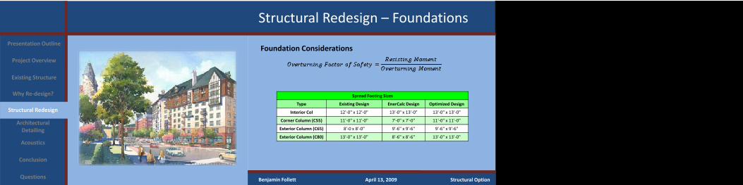
Foundation ConsiderationsProject Overview
Existing Structure
Why Re‐design?
Structural Redesign
Architectural Detailing
Conclusion
Acoustics
Questions
Presentation Outline
Benjamin Follett April 13, 2009 Structural Option
Spread Footing Sizes
Type Existing Design EnerCalc Design Optimized Design
Interior Col 12'‐0" x 12'‐0" 13'‐0" x 13'‐0" 13'‐0" x 13'‐0"
Corner Column (C55) 11'‐0" x 11'‐0" 7'‐0" x 7'‐0" 11'‐0" x 11'‐0"
Exterior Column (C65) 8'‐0 x 8'‐0" 9'‐6" x 9'‐6" 9'‐6" x 9'‐6"
Exterior Column (C80) 13'‐0" x 13'‐0" 8'‐6" x 8'‐6" 13'‐0" x 13'‐0"
Structural Redesign – Lateral System
Project Overview
Existing Structure
Why Re‐design?
Structural Redesign
Architectural Detailing
Conclusion
Acoustics
Questions
Presentation Outline
Benjamin Follett April 13, 2009 Structural Option
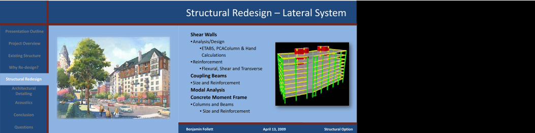
Shear Walls•Analysis/Design
•ETABS, PCAColumn & Hand Calculations
•Reinforcement •Flexural, Shear and Transverse
Coupling Beams•Size and Reinforcement
Modal AnalysisConcrete Moment Frame•Columns and Beams
• Size and Reinforcement

Structural Redesign – Lateral System
Reinforced Concrete Shear Walls• Placement of Shear Walls around Stair and Elevator ShaftsProject Overview
Existing Structure
Why Re‐design?
Structural Redesign
Architectural Detailing
Conclusion
Acoustics
Questions
Presentation Outline
Benjamin Follett April 13, 2009 Structural Option
SL2
SB2 SR2
ST2ET2
ER2
EB2
EL2
ET1
EL1ER1
EB1
SL2SB1
SR1
ST1
Structural Redesign – Lateral System
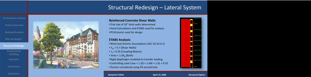
Reinforced Concrete Shear Walls•Trial size of 18” thick walls determined•Hand Calculations and ETABS used for analysis•PCAColumn used for design
ETABS Analysis•Wind and Seismic Assumptions (ACI 10.10.4.1)• f22 = 0.7 (Shear Walls)• I3 = 0.35 (Coupling Beams)• Area = 1.0Ag (Both)•Rigid diaphragm modeled to transfer loading•Controlling Load Case = 1.2D + 1.6W + 1.0L + 0.5S•Torsion considered using 5% eccentricity
Project Overview
Existing Structure
Why Re‐design?
Structural Redesign
Architectural Detailing
Conclusion
Acoustics
Questions
Presentation Outline
Benjamin Follett April 13, 2009 Structural Option
Structural Redesign – Lateral System
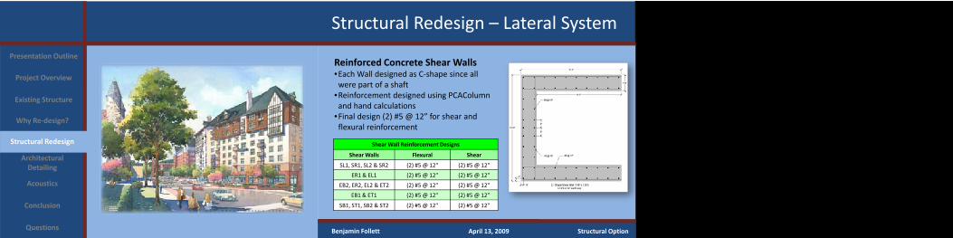
Reinforced Concrete Shear Walls•Each Wall designed as C‐shape since all were part of a shaft
•Reinforcement designed using PCAColumn and hand calculations
•Final design (2) #5 @ 12” for shear and flexural reinforcement
Project Overview
Existing Structure
Why Re‐design?
Structural Redesign
Architectural Detailing
Conclusion
Acoustics
Questions
Presentation Outline
Benjamin Follett April 13, 2009 Structural Option
Shear Wall Reinforcement Designs
Shear Walls Flexural Shear
SL1, SR1, SL2 & SR2 (2) #5 @ 12" (2) #5 @ 12"
ER1 & EL1 (2) #5 @ 12" (2) #5 @ 12"
EB2, ER2, EL2 & ET2 (2) #5 @ 12" (2) #5 @ 12"
EB1 & ET1 (2) #5 @ 12" (2) #5 @ 12"
SB1, ST1, SB2 & ST2 (2) #5 @ 12" (2) #5 @ 12"
Structural Redesign – Lateral System
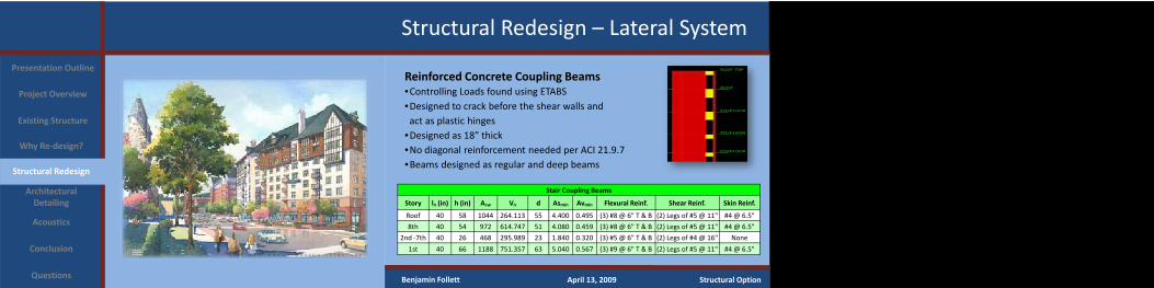
Reinforced Concrete Coupling Beams•Controlling Loads found using ETABS•Designed to crack before the shear walls andact as plastic hinges
•Designed as 18” thick•No diagonal reinforcement needed per ACI 21.9.7•Beams designed as regular and deep beams
Project Overview
Existing Structure
Why Re‐design?
Structural Redesign
Architectural Detailing
Conclusion
Acoustics
Questions
Presentation Outline
Benjamin Follett April 13, 2009 Structural Option
Stair Coupling Beams
Story ln (in) h (in) Acw Vn d Asmin Avmin Flexural Reinf. Shear Reinf. Skin Reinf.
Roof 40 58 1044 264.113 55 4.400 0.495 (3) #8 @ 6" T & B (2) Legs of #5 @ 11" #4 @ 6.5"
8th 40 54 972 614.747 51 4.080 0.459 (3) #8 @ 6" T & B (2) Legs of #5 @ 11" #4 @ 6.5"
2nd ‐7th 40 26 468 295.989 23 1.840 0.320 (3) #5 @ 6" T & B (2) Legs of #4 @ 16" None
1st 40 66 1188 751.357 63 5.040 0.567 (3) #9 @ 6" T & B (2) Legs of #5 @ 11" #4 @ 6.5"

Structural Redesign – Lateral System
Reinforced Concrete Coupling Beams•Controlling Loads found using ETABS•Designed to crack before the shear walls andact as plastic hinges
•Designed as 18” thick•No diagonal reinforcement needed per ACI 21.9.7•Beams designed as regular and deep beams
Project Overview
Existing Structure
Why Re‐design?
Structural Redesign
Architectural Detailing
Conclusion
Acoustics
Questions
Presentation Outline
Benjamin Follett April 13, 2009 Structural Option
Elevator Coupling Beams
Story ln (in) h (in) Acw Vn d Asmin Avmin Flexural Reinf. Shear Reinf. Skin Reinf.
ROOF 46 58 1044 660.284 55 4.400 0.495 (3) #8 @ 6" T & B (2) Legs of #5 @ 11" #4 @ 6"
8th 46 54 972 614.747 51 4.080 0.459 (3) #8 @ 6" T & B (2) Legs of #5 @ 11" #4 @ 6"
2nd ‐ 7th 46 26 468 295.989 23 1.840 0.320 (3) #5 @ 6" T & B (2) Legs of #4 @ 16" None
1st 46 66 1188 751.357 63 5.040 0.567 (3) #9 @ 6" T & B (2) Legs of #5 @ 11" #4 @ 6"
Structural Redesign – Lateral System
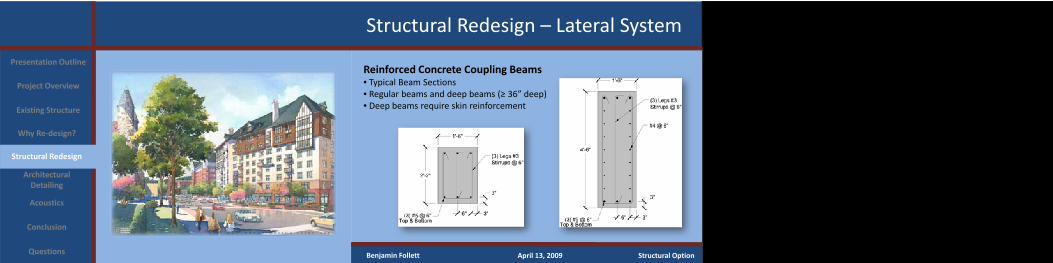
Reinforced Concrete Coupling Beams• Typical Beam Sections• Regular beams and deep beams (≥ 36” deep)• Deep beams require skin reinforcement
Project Overview
Existing Structure
Why Re‐design?
Structural Redesign
Architectural Detailing
Conclusion
Acoustics
Questions
Presentation Outline
Benjamin Follett April 13, 2009 Structural Option
Structural Redesign – Lateral System
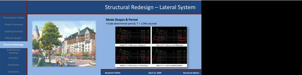
Mode Shapes & Period• Code determined period, T = 1.046 seconds Project Overview
Existing Structure
Why Re‐design?
Structural Redesign
Architectural Detailing
Conclusion
Acoustics
Questions
Presentation Outline
Benjamin Follett April 13, 2009 Structural Option
Structural Redesign – Lateral System
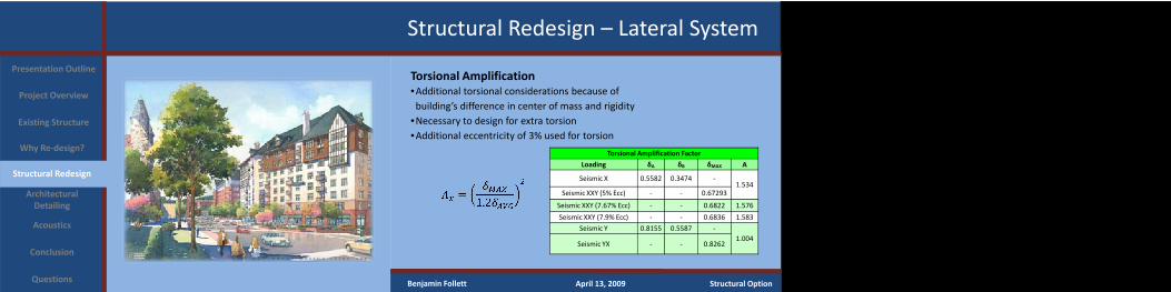
Torsional Amplification•Additional torsional considerations because of building’s difference in center of mass and rigidity
•Necessary to design for extra torsion•Additional eccentricity of 3% used for torsion
Project Overview
Existing Structure
Why Re‐design?
Structural Redesign
Architectural Detailing
Conclusion
Acoustics
Questions
Presentation Outline
Benjamin Follett April 13, 2009 Structural Option
Torsional Amplification Factor
Loading δA δB δMAX A
Seismic X 0.5582 0.3474 ‐1.534
Seismic XXY (5% Ecc) ‐ ‐ 0.67293
Seismic XXY (7.67% Ecc) ‐ ‐ 0.6822 1.576
Seismic XXY (7.9% Ecc) ‐ ‐ 0.6836 1.583
Seismic Y 0.8155 0.5587 ‐1.004
Seismic YX ‐ ‐ 0.8262
Structural Redesign – Lateral System
Torsional Amplification•Additional torsional considerations because of building’s difference in center of mass and rigidity
•Necessary to design for extra torsion•Additional eccentricity of 3% used for torsion
Project Overview
Existing Structure
Why Re‐design?
Structural Redesign
Architectural Detailing
Conclusion
Acoustics
Questions
Presentation Outline
Benjamin Follett April 13, 2009 Structural Option
As a result of accidental torsion and the desire to investigate, additional lateral systems, exterior
moment frames were designed.
Structural Redesign – Lateral System
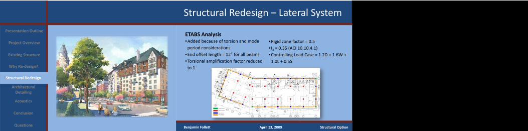
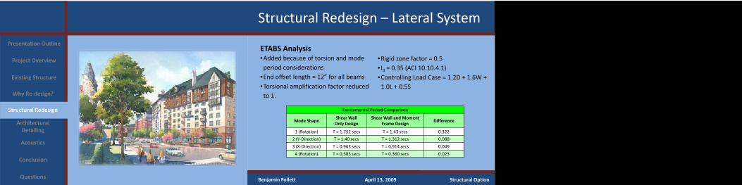
ETABS Analysis•Added because of torsion and mode period considerations
•End offset length = 12” for all beams•Torsional amplification factor reduced to 1.
Project Overview
Existing Structure
Why Re‐design?
Structural Redesign
Architectural Detailing
Conclusion
Acoustics
Questions
Presentation Outline
Benjamin Follett April 13, 2009 Structural Option
•Rigid zone factor = 0.5• I3 = 0.35 (ACI 10.10.4.1)•Controlling Load Case = 1.2D + 1.6W + 1.0L + 0.5S
Structural Redesign – Lateral System
ETABS Analysis•Added because of torsion and mode period considerations
•End offset length = 12” for all beams•Torsional amplification factor reduced to 1.
Project Overview
Existing Structure
Why Re‐design?
Structural Redesign
Architectural Detailing
Conclusion
Acoustics
Questions
Presentation Outline
Benjamin Follett April 13, 2009 Structural Option
Fundamental Period Comparison
Mode ShapeShear Wall Only Design
Shear Wall and Moment Frame Design
Difference
1 (Rotation) T = 1.752 secs T = 1.43 secs 0.322
2 (Y‐Direction) T = 1.40 secs T = 1.312 secs 0.088
3 (X‐Direction) T = 0.963 secs T = 0.914 secs 0.049
4 (Rotation) T = 0.383 secs T = 0.360 secs 0.023
•Rigid zone factor = 0.5• I3 = 0.35 (ACI 10.10.4.1)•Controlling Load Case = 1.2D + 1.6W + 1.0L + 0.5S
Structural Redesign – Lateral System
Benjamin Follett April 13, 2009 Structural Option
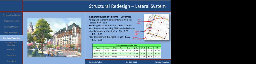
Concrete Moment Frame ‐ Columns•Designed as intermediate moment frame as stated in ACI 21.3
•Redesign of all exterior and corner columns•Loads determined using ETABS and takedowns•Load Case (long direction) = 1.2D + 1.0E + 1.0L + 0.2S
•Load Case (short direction) = 1.2D + 1.6W + 1.0L + 0.5S
Concrete Column Loading (kips)
Type Area Self Wt. Dead Live Quake Wind Snow LC
Corner (C55) 118.75 49.027 194.750 53.438 9.320 42.520 2.731 415.37
Exterior 1 (C65) 314.71 49.027 516.124 141.620 20.280 20.200 7.238 855.74
Exterior 2 (C80) 240.33 49.027 394.141 108.149 14.600 13.020 5.528 663.55
Corner Column (C55)
Project Overview
Existing Structure
Why Re‐design?
Structural Redesign
Architectural Detailing
Conclusion
Acoustics
Questions
Presentation Outline
ExteriorColumn (C80)
Exterior Column (C65)
Structural Redesign – Lateral System
Benjamin Follett April 13, 2009 Structural Option
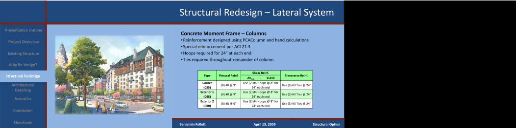
Concrete Moment Frame – Columns•Reinforcement designed using PCAColumn and hand calculations•Special reinforcement per ACI 21.3•Hoops required for 24” at each end•Ties required throughout remainder of column
Type Flexural Reinf.Shear Reinf.
Transverse Reinf.Avmin 0.240
Corner (C55)
(8) #8 @ 9"Use (2) #4 Hoops @ 8" for
24" each endUse (3) #3 Ties @ 24"
Exterior 1 (C65)
(8) #8 @ 9"Use (2) #4 Hoops @ 8" for
24" each endUse (3) #3 Ties @ 24"
Exterior 2 (C80)
(8) #8 @ 9"Use (2) #4 Hoops @ 8" for
24" each endUse (3) #3 Ties @ 24"
Project Overview
Existing Structure
Why Re‐design?
Structural Redesign
Architectural Detailing
Conclusion
Acoustics
Questions
Presentation Outline
Structural Redesign – Lateral System
Benjamin Follett April 13, 2009 Structural Option
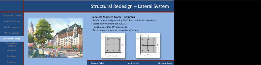
Concrete Moment Frame – Columns•Reinforcement designed using PCAColumn and hand calculations•Special reinforcement per ACI 21.3•Hoops required for 24” at each end•Ties required throughout remainder of column
Project Overview
Existing Structure
Why Re‐design?
Structural Redesign
Architectural Detailing
Conclusion
Acoustics
Questions
Presentation Outline
Structural Redesign – Lateral System
Benjamin Follett April 13, 2009 Structural Option
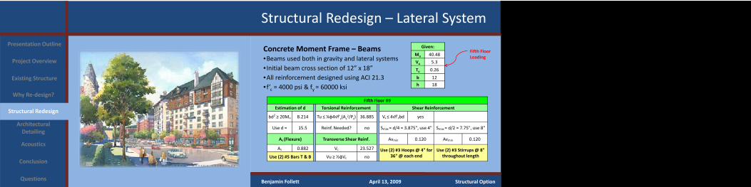
Concrete Moment Frame – Beams•Beams used both in gravity and lateral systems• Initial beam cross section of 12” x 18”•All reinforcement designed using ACI 21.3• f’c = 4000 psi & fy = 60000 ksi
Project Overview
Existing Structure
Why Re‐design?
Structural Redesign
Architectural Detailing
Conclusion
Acoustics
Questions
Presentation Outline
Fifth Floor B9
Estimation of d Torsional Reinforcement Shear Reinforcement
bd2 ≥ 20Mu 8.214 Tu ≤ ¼φ4√f'c(Ac2/Pc) 36.885 Vs ≤ 4√f'cbd yes
Use d = 15.5 Reinf. Needed? no Smax = d/4 = 3.875", use 4" Smax = d/2 = 7.75", use 8"
As (Flexure) Transverse Shear Reinf. Avmin 0.120 Avmin 0.120
As 0.882 Vc 23.527 Use (2) #3 Hoops @ 4" for 36" @ each end
Use (2) #3 Stirrups @ 8" throughout lengthUse (2) #5 Bars T & B Vu ≥ ½φVc no
Given:
Mu 40.48
Vu 5.3
Tu 0.26
b 12
h 18
Fifth Floor Loading

Structural Redesign – Lateral System
Benjamin Follett April 13, 2009 Structural Option
Concrete Moment Frame – Beams DetailsProject Overview
Existing Structure
Why Re‐design?
Structural Redesign
Architectural Detailing
Conclusion
Acoustics
Questions
Presentation Outline
End Beam Detail Throughout Beam Detail
Structural Redesign – Lateral System
Benjamin Follett April 13, 2009 Structural Option
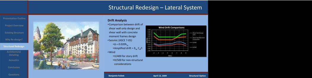
Drift Analysis•Comparison between drift of shear wall only design and shear wall with concrete moment frames design
•Seismic (ASCE 7‐05)•∆ = 0.020hsx•Amplified drift = δxe Cd/I
•Wind•H/400 for story drift•H/500 for non‐structural considerations
Project Overview
Existing Structure
Why Re‐design?
Structural Redesign
Architectural Detailing
Conclusion
Acoustics
Questions
Presentation Outline
0.00
0.050.10
0.15
0.200.25
0.30
0.350.40
0.45
0.50
2 3 4 5 6 7 8 9
Drift (in)
Story
Wind Drift Comparisons
Shear Wall Design Drift
Shear Wall/Moment Frame Drift
H/400
H/500
Structural Redesign – Lateral System
Benjamin Follett April 13, 2009 Structural Option
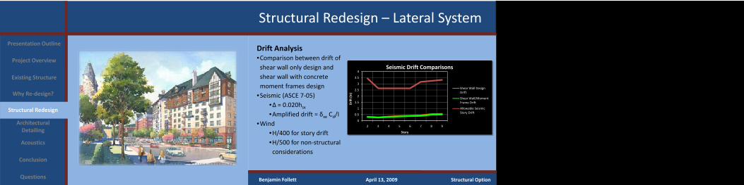
Drift Analysis•Comparison between drift of shear wall only design and shear wall with concrete moment frames design
•Seismic (ASCE 7‐05)•∆ = 0.020hsx•Amplified drift = δxe Cd/I
•Wind•H/400 for story drift•H/500 for non‐structural considerations
Project Overview
Existing Structure
Why Re‐design?
Structural Redesign
Architectural Detailing
Conclusion
Acoustics
Questions
Presentation Outline
0
0.5
1
1.5
2
2.5
3
3.5
4
2 3 4 5 6 7 8 9
Drift (in)
Story
Seismic Drift Comparisons
Shear Wall Design Drift
Shear Wall/Moment Frame Drift
Allowable Seismic Story Drift
Architectural Detailing Study
Project Overview
Existing Structure
Why Re‐design?
Structural Redesign
Architectural Detailing
Conclusion
Acoustics
Questions
Presentation Outline
Benjamin Follett April 13, 2009 Structural Option
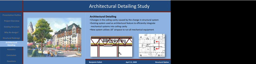
Architectural Detailing •Changes in the ceiling cavity caused by the change in structural system•Existing system used as architectural feature to efficiently integrate mechanical systems into ceiling cavity
•New system utilizes 18” airspace to run all mechanical equipment
Architectural Detailing Study
Project Overview
Existing Structure
Why Re‐design?
Structural Redesign
Architectural Detailing
Conclusion
Acoustics
Questions
Presentation Outline
Benjamin Follett April 13, 2009 Structural Option
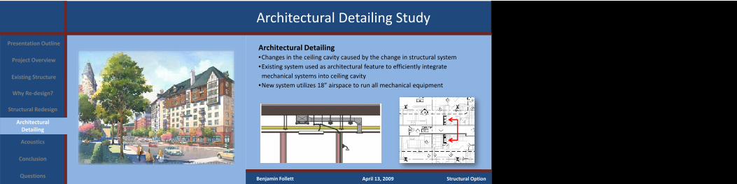
Architectural Detailing •Changes in the ceiling cavity caused by the change in structural system•Existing system used as architectural feature to efficiently integrate mechanical systems into ceiling cavity
•New system utilizes 18” airspace to run all mechanical equipment
Architectural Detailing Study
Project Overview
Existing Structure
Why Re‐design?
Structural Redesign
Architectural Detailing
Conclusion
Acoustics
Questions
Presentation Outline
Benjamin Follett April 13, 2009 Structural Option
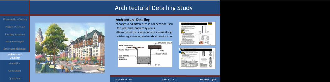
Architectural Detailing •Changes and differences in connections used for steel and concrete systems
•New connection uses concrete screws along with a lag screw expansion shield and anchor
Acoustics Breadth Study
Project Overview
Existing Structure
Why Re‐design?
Structural Redesign
Architectural Detailing
Conclusion
Acoustics
Questions
Presentation Outline
Benjamin Follett April 13, 2009 Structural Option
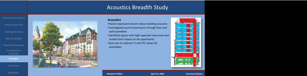
Acoustics•Owner expressed concern about building acoustics• Investigated sound transmission through floor and wall assemblies
• Identified spaces with high expected noise level and studied their impact on the apartments
•Goal was to improve TL and STC values for assemblies
Acoustics Breadth Study
Project Overview
Existing Structure
Why Re‐design?
Structural Redesign
Architectural Detailing
Conclusion
Acoustics
Questions
Presentation Outline
Benjamin Follett April 13, 2009 Structural Option
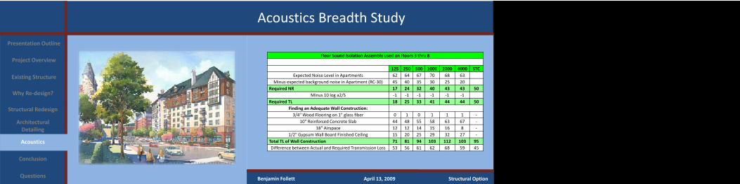
Floor Sound Isolation Assembly used on Floors 3 thru 8
125 250 500 1000 2000 4000 STCExpected Noise Level in Apartments 62 64 67 70 68 63
Minus expected background noise in Apartment (RC‐30) 45 40 35 30 25 20Required NR 17 24 32 40 43 43 50
Minus 10 log a2/S ‐1 ‐1 ‐1 ‐1 ‐1 ‐1Required TL 18 25 33 41 44 44 50
Finding an Adequate Wall Construction:3/4" Wood Flooring on 1" glass fiber 0 1 0 1 1 1 ‐
10" Reinforced Concrete Slab 44 48 55 58 63 67 ‐18" Airspace 12 12 14 15 16 8 ‐
1/2" Gypsum Wall Board Finished Ceiling 15 20 25 29 32 27 ‐Total TL of Wall Construction 71 81 94 103 112 103 95Difference between Actual and Required Transmission Loss 53 56 61 62 68 59 45
Acoustics Breadth Study
Project Overview
Existing Structure
Why Re‐design?
Structural Redesign
Architectural Detailing
Conclusion
Acoustics
Questions
Presentation Outline
Benjamin Follett April 13, 2009 Structural Option
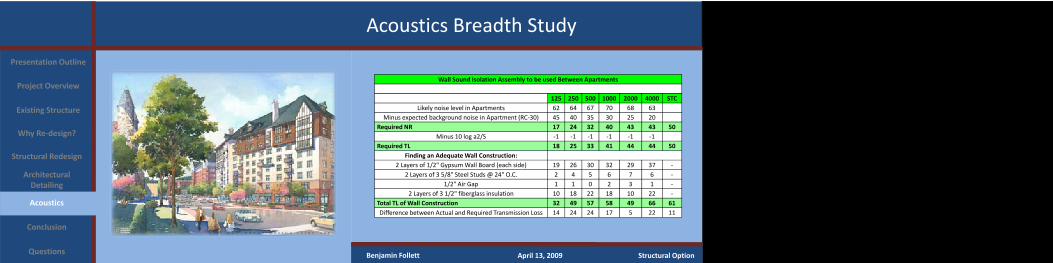
Wall Sound Isolation Assembly to be used Between Apartments
125 250 500 1000 2000 4000 STCLikely noise level in Apartments 62 64 67 70 68 63
Minus expected background noise in Apartment (RC‐30) 45 40 35 30 25 20Required NR 17 24 32 40 43 43 50
Minus 10 log a2/S ‐1 ‐1 ‐1 ‐1 ‐1 ‐1Required TL 18 25 33 41 44 44 50
Finding an Adequate Wall Construction:2 Layers of 1/2" Gypsum Wall Board (each side) 19 26 30 32 29 37 ‐
2 Layers of 3 5/8" Steel Studs @ 24" O.C. 2 4 5 6 7 6 ‐1/2" Air Gap 1 1 0 2 3 1 ‐
2 Layers of 3 1/2" fiberglass insulation 10 18 22 18 10 22 ‐Total TL of Wall Construction 32 49 57 58 49 66 61Difference between Actual and Required Transmission Loss 14 24 24 17 5 22 11
Acoustics Breadth Study
Project Overview
Existing Structure
Why Re‐design?
Structural Redesign
Architectural Detailing
Conclusion
Acoustics
Questions
Presentation Outline
Benjamin Follett April 13, 2009 Structural Option
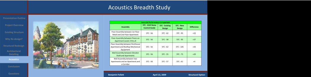
Acoustic Performance Comparison
AssemblySTC ‐ HUD Noise Control Guide
STC ‐ Existing Design
STC ‐ New Design
Difference
Floor Assembly between 1st Floor Retail and 2nd Floor Apartment
STC ‐ 56 STC ‐ 62 STC ‐ 95 +33
Floor Assembly between Floors on Apartment Levels 3 thru 8
STC ‐ 56 STC ‐ 58 STC ‐ 95 +37
Floor Assembly between Penthouse Apartment and Rooftop Mechanical
EquipmentSTC ‐ 56 STC ‐ 62 STC ‐ 105 +43
Wall Assembly between Elevator Shaft and Apartments
STC ‐ 56 STC ‐ 55 STC ‐ 75 +20
Wall Assembly between two Apartments and an Apartment and
a CorridorSTC ‐ 56 STC ‐ 57 STC ‐ 61 +4

Conclusions and Recommendations
Project Overview
Existing Structure
Why Re‐design?
Structural Redesign
Architectural Detailing
Conclusion
Acoustics
Questions
Presentation Outline
Benjamin Follett April 13, 2009 Structural Option
Conclusions and Recommendations•Redesign of structural system caused the following:
•Reduced building motion in terms of building period and drift•Possible overdesign with the inclusion of concrete moment frames•Minor impacts on architectural aspects of the building•Better acoustical performance of all floor/wall assemblies
•Recommendations•Existing structural system is most likely the most efficient•Benefits of the use of reinforced concrete in the design of mid‐rise apartment buildings is evident
Overall, the main objective of learning how to analyze and design all aspects of a concrete structure was accomplished!

Acknowledgements
Project Overview
Existing Structure
Why Re‐design?
Structural Redesign
Architectural Detailing
Conclusion
Acoustics
Questions
Presentation Outline
Benjamin Follett April 13, 2009 Structural Option
Zamagias PropertiesMichael Heins
WBCM, LLCBrian Channer, PEMike Wuerthele, PE, Senior VPBrandon PettnerJeremy Urban
Indovina Associates ArchitectsBrian Roth, AIA
CJL EngineeringGary CzyrnikHarry Hoover
The Penn State UniversityProf. M.K. ParfittDr. Linda M. HanaganProf. Robert J. HollandDr. Ali Memari
AE StudentsScott Rabold & the Bat Cave
Lastly, I would like to thank all of my peers in the AE program, along with my family and friends for their endless support and encouragement through this entire project. Your help was invaluable and for that I am extremely grateful.
Questions?
Project Overview
Existing Structure
Why Re‐design?
Structural Redesign
Architectural Detailing
Conclusion
Acoustics
Questions
Presentation Outline
Benjamin Follett April 13, 2009 Structural Option