Embed Size (px)
Citation preview
1
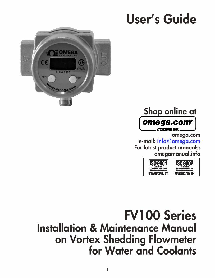
User’s Guide
Shop online at
FV100 Series
Installation & Maintenance Manual on Vortex Shedding Flowmeter
for Water and Coolants
omega.com e-mail: [email protected]
For latest product manuals: omegamanual.info
2
U.S.A. and Canada: Sales Service: 1-800-826-6342 / 1-800-TC-OMEGA®
Customer Service: 1-800-622-2378 / 1-800-622-BEST®
Engineering Service: 1-800-872-9436 / 1-800-USA-WHEN®
TELEX: 996404 EASYLINK: 62968934 CABLE: OMEGA
Mexico: En Español: (001) 203-359-7803 e-mail: [email protected]
FAX: (001) 203-359-7807 [email protected]
Servicing Europe: Benelux: Postbus 8034, 1180 LA Amstelveen, The Netherlands
TEL: +31 (0)20 3472121 FAX: +31 (0)20 6434643
Toll Free in Benelux: 0800 0993344 e-mail: [email protected]
Czech Republic: Frystatska 184, 733 01 Karviná, Czech Republic
TEL: +420 (0)59 6311899 FAX: +420 (0)59 6311114
Toll Free: 0800-1-66342 e-mail: [email protected]
France: 11, rue Jacques Cartier, 78280 Guyancourt, France
TEL: +33 (0)1 61 37 2900 FAX: +33 (0)1 30 57 5427
Toll Free in France: 0800 466 342 e-mail: [email protected]
Germany/Austria: Daimlerstrasse 26, D-75392 Deckenpfronn, Germany
TEL: +49 (0)7056 9398-0 FAX: +49 (0)7056 9398-29
Toll Free in Germany: 0800 639 7678 e-mail: [email protected]
United Kingdom: One Omega Drive, River Bend Technology Centre
ISO 9002 Certified Northbank, Irlam, Manchester
M44 5BD United Kingdom
TEL: +44 (0)161 777 6611 FAX: +44 (0)161 777 6622
Toll Free in United Kingdom: 0800-488-488
e-mail: [email protected]
It is the policy of OMEGA Engineering, Inc. to comply with all worldwide safety and EMC/EMI regulations that apply. OMEGA is constantly pursuing certification of its products to the European New Approach Directives. OMEGA will add the CE mark to every appropriate device upon certification. The information contained in this document is believed to be correct, but OMEGA accepts no liability for any errors it contains, and reserves the right to alter specifications without notice. WARNING: These products are not designed for use in, and should not be used for, human applications.
Servicing North America:
For immediate technical or application assistance:
U.S.A.: One Omega Drive, P.O. Box 4047 ISO 9001 Certified Stamford, CT 06907-0047 TEL: (203) 359-1660 FAX: (203) 359-7700
e-mail: [email protected] Canada: 976 Bergar Laval (Quebec) H7L 5A1, Canada TEL: (514) 856-6928 FAX: (514) 856-6886
e-mail: [email protected]
3
CONTENTS
Subject Page
Specifications ................................................................................... 4
How It Works .................................................................................... 4
Applications ...................................................................................... 5
Using This Manual ........................................................................... 5
Features .......................................................................................... 5
Installation ....................................................................................... 6
Electrical /Wiring /Grounding .......................................................... 6
Wiring Diagram /DC Power Supply Voltage Requirements ........... 7
Setup and Configuration ................................................................. 8
Model Codes ................................................................................. 11
Installation Drawings ..................................................................... 11
Pressure Drop Data ...................................................................... 11
Warranty ......................................................................................... 12
4
Specifications Maximum operating pressure: 200 PSIG (13.78 Bar)
Minimum operating pressure: See pressure drop data, Page 7
Maximum operating temperature (fluid and ambient): 185°F (85ºC), 186°F to 210°F (85ºC to 99ºC) with
reduced rating of the solid state relay.
Minimum operating temperature (fluid and ambient): 35°F (2ºC).
Enclosure Rating: IP65, Type 1, 3, 4, 12, & 13
Analog Output: 4 - 20 mA (600 OHM @ 24 VDC)
Response Time: 1.5 sec to 63% of flow
Accuracy: ± 5% of Full Scale
Alarm Output: Solid State Relay, optically isolated, 250 mA @ 30 VDC
Deadband: 2.5 % Full Scale
Power: 10 - 30 VDC @ 80 mA
Caution: The unit shall be supplied by a SELV (separated extra-low voltage) source in accordance with
CSA Standard C22.2 No.1010.1-92 Annex H.
Electrical Connection: 5 - Pin micro male connector
Capacities: 1/4" 4 GPM, 1/2" 12 GPM
Process Connections: NPT Female
Wetted Parts: Brass or Stainless Steel, PVDF & Viton
Environmental conditions: This device has been designed for use in Installation category I, pollution
degree 4, at altitudes up to 2000 meters (6560 ft.), either indoors or outdoors as defined in CSA
Standard C22.2 No.1010.1-92.
HOW IT WORKS The FV100 is an inline flow meter that utilizes the vortex shedding measuring principle. The fluid
strikes a bluff body which imparts alternating vortices downstream of the bluff which create a pressure
on a sensor body containing a piezoelectric crystal. The frequency of the sensor is proportional to the
velocity of the fluid and is amplified and converted to a 4-20mA output linear with flow. Vortex tech-
nology yields a meter with no moving parts to hang up or wear.
The meter has a bright .3 inch high LED display of flow in either liters or gallons. It can be mounted
with flow in any direction and the display can be rotated 180 degrees in the field for viewing conve-
nience. The meter requires a nominal 24 VDC power source and outputs a visual display of flow, as well
as 4-20 mA proportional to flow, and a field settable solid state relay for low flow alarm conditions. The
meters come pre-calibrated for the specific range as determined by size. The turndown is 10: 1 and the
accuracy is better than 5% of full scale flow.
5
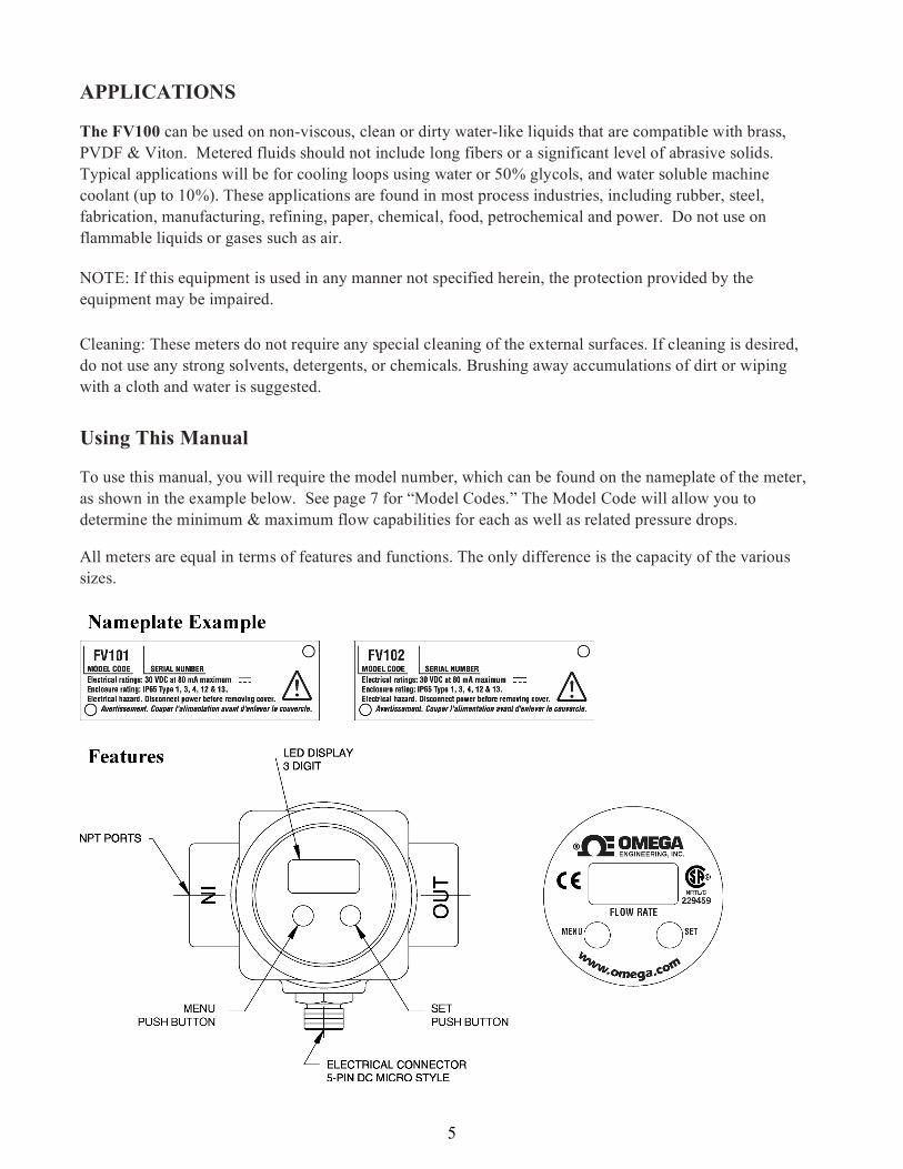
APPLICATIONS
Using This Manual
To use this manual, you will require the model number, which can be found on the nameplate of the meter,
as shown in the example below. See page 7 for “Model Codes.” The Model Code will allow you to
determine the minimum & maximum flow capabilities for each as well as related pressure drops.
All meters are equal in terms of features and functions. The only difference is the capacity of the various
sizes.
Cleaning: These meters do not require any special cleaning of the external surfaces. If cleaning is desired,
do not use any strong solvents, detergents, or chemicals. Brushing away accumulations of dirt or wiping
with a cloth and water is suggested.
The FV100 can be used on non-viscous, clean or dirty water-like liquids that are compatible with brass,
PVDF & Viton. Metered fluids should not include long fibers or a significant level of abrasive solids.
Typical applications will be for cooling loops using water or 50% glycols, and water soluble machine
coolant (up to 10%). These applications are found in most process industries, including rubber, steel,
fabrication, manufacturing, refining, paper, chemical, food, petrochemical and power. Do not use on
flammable liquids or gases such as air.
NOTE: If this equipment is used in any manner not specified herein, the protection provided by the
equipment may be impaired.
6
Installation
There are no upstream or downstream piping requirements to achieve the operating specifications given
herein. The meters may be installed in any position as long as good piping installation requirements are
adhered to for best results. This includes proper support of adjacent piping to minimize inherent vibrations
produced within the system. Unions of the same pipe size and full port isolation ball valves may be installed
for ease of removal and servicing, if required.
Isolation ball valves, when used, should be in the full open position. Throttling valves should always be
placed down stream of the meter.
Teflon tape or pipe sealants can be used in mounting the meter to the piping when using good technique.
Use of diaphragm or piston pumps will affect metering performance, unless they are installed with
properly sized pulsation dampeners and pressure control valves. The piping system must create some back
pressure on the meter to prevent cavitation, especially at full flow.
Electrical/Wiring/Grounding
Electrical Service: General Purpose
Electrical Classification: Non-hazardous, Type 1, 3, 4 (equal to IP 65), 12 & 13
Power Requirements: 24 VDC (10 - 30 VDC) @ 80 mA
Electrical Connection: 5-Pin micro style, DC
Cabling: 5-Pin Female shielded cable (cable is grounded at the connection - do not connect shield at the
panel; unless piping is non-conductive)
Current Output: 4- 20 mA (600 OHM @ 24 VDC) (Note: Use of a 250 OHM 0.1% 1/2 -watt precision
resistor for voltage input receivers will produce a 1-5 VDC signal.
Solid State Relay: Optically isolated, current limited to 250 mA @ 30 VDC
Grounding: Proper grounding is required to eliminate electrical noise which may be present within the fluid
and piping system. This noise can get coupled into the flowmeter sensor and result in a false flow reading
at the low end.
If the flowmeter output indicates flow when there is no flow, try the following:
1. Place a 0.1 microfarad capacitor between DC power supply ground (pin 3) and Chassis ground (shield).
Chassis ground is the same as the piping or the fluid. The voltage rating on the capacitor should be more than
100 volts.
2. Connect the DC and Chassis grounds together.
7
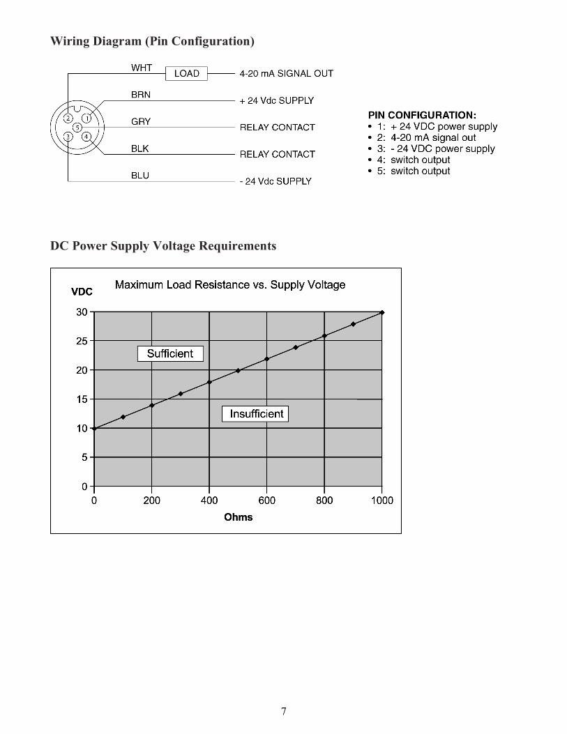
Wiring Diagram (Pin Configuration)
DC Power Supply Voltage Requirements
8
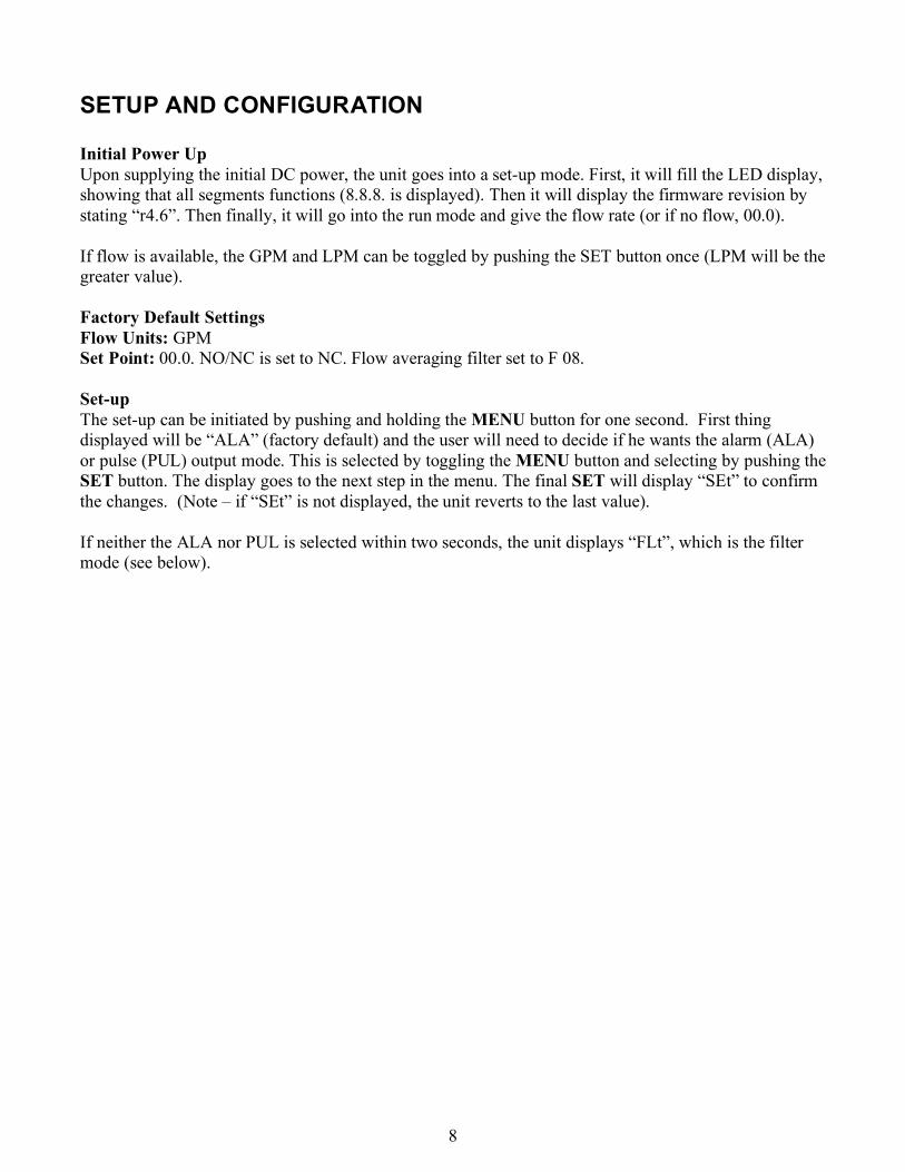
SETUP AND CONFIGURATION
Initial Power Up
Upon supplying the initial DC power, the unit goes into a set-up mode. First, it will fill the LED display,
showing that all segments functions (8.8.8. is displayed). Then it will display the firmware revision by
stating “r4.6”. Then finally, it will go into the run mode and give the flow rate (or if no flow, 00.0).
If flow is available, the GPM and LPM can be toggled by pushing the SET button once (LPM will be the
greater value).
Factory Default Settings
Flow Units: GPM
Set Point: 00.0. NO/NC is set to NC. Flow averaging filter set to F 08.
Set-up
The set-up can be initiated by pushing and holding the MENU button for one second. First thing
displayed will be “ALA” (factory default) and the user will need to decide if he wants the alarm (ALA)
or pulse (PUL) output mode. This is selected by toggling the MENU button and selecting by pushing the
SET button. The display goes to the next step in the menu. The final SET will display “SEt” to confirm
the changes. (Note – if “SEt” is not displayed, the unit reverts to the last value).
If neither the ALA nor PUL is selected within two seconds, the unit displays “FLt”, which is the filter
mode (see below).
9
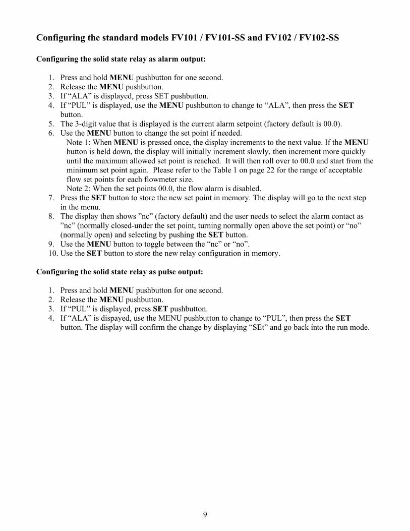
Configuring the standard models FV101 / FV101-SS and FV102 / FV102-SS
Configuring the solid state relay as alarm output:
1. Press and hold MENU pushbutton for one second.
2. Release the MENU pushbutton.
3. If “ALA” is displayed, press SET pushbutton.
4. If “PUL” is displayed, use the MENU pushbutton to change to “ALA”, then press the SET
button.
5. The 3-digit value that is displayed is the current alarm setpoint (factory default is 00.0).
6. Use the MENU button to change the set point if needed.
Note 1: When MENU is pressed once, the display increments to the next value. If the MENU
button is held down, the display will initially increment slowly, then increment more quickly
until the maximum allowed set point is reached. It will then roll over to 00.0 and start from the
minimum set point again. Please refer to the Table 1 on page 22 for the range of acceptable
flow set points for each flowmeter size.
Note 2: When the set points 00.0, the flow alarm is disabled.
7. Press the SET button to store the new set point in memory. The display will go to the next step
in the menu.
8. The display then shows ”nc” (factory default) and the user needs to select the alarm contact as
”nc” (normally closed-under the set point, turning normally open above the set point) or “no”
(normally open) and selecting by pushing the SET button.
9. Use the MENU button to toggle between the “nc” or “no”.
10. Use the SET button to store the new relay configuration in memory.
Configuring the solid state relay as pulse output:
1. Press and hold MENU pushbutton for one second.
2. Release the MENU pushbutton.
3. If “PUL” is displayed, press SET pushbutton.
4. If “ALA” is dispayed, use the MENU pushbutton to change to “PUL”, then press the SET
button. The display will confirm the change by displaying “SEt” and go back into the run mode.
10
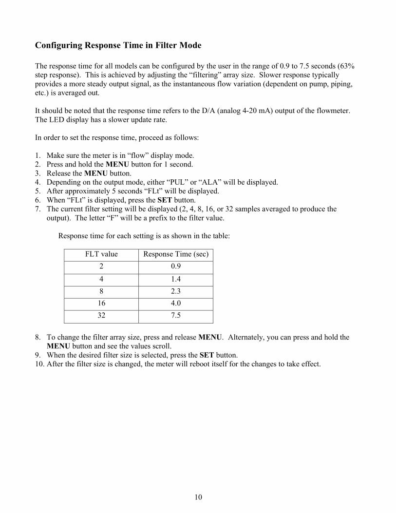
Configuring Response Time in Filter Mode
The response time for all models can be configured by the user in the range of 0.9 to 7.5 seconds (63%
step response). This is achieved by adjusting the “filtering” array size. Slower response typically
provides a more steady output signal, as the instantaneous flow variation (dependent on pump, piping,
etc.) is averaged out.
It should be noted that the response time refers to the D/A (analog 4-20 mA) output of the flowmeter.
The LED display has a slower update rate.
In order to set the response time, proceed as follows:
1. Make sure the meter is in “flow” display mode.
2. Press and hold the MENU button for 1 second.
3. Release the MENU button.
4. Depending on the output mode, either “PUL” or “ALA” will be displayed.
5. After approximately 5 seconds “FLt” will be displayed.
6. When “FLt” is displayed, press the SET button.
7. The current filter setting will be displayed (2, 4, 8, 16, or 32 samples averaged to produce the
output). The letter “F” will be a prefix to the filter value.
Response time for each setting is as shown in the table:
FLT value Response Time (sec)
2 0.9
4 1.4
8 2.3
16 4.0
32 7.5
8. To change the filter array size, press and release MENU. Alternately, you can press and hold the
MENU button and see the values scroll.
9. When the desired filter size is selected, press the SET button.
10. After the filter size is changed, the meter will reboot itself for the changes to take effect.
11
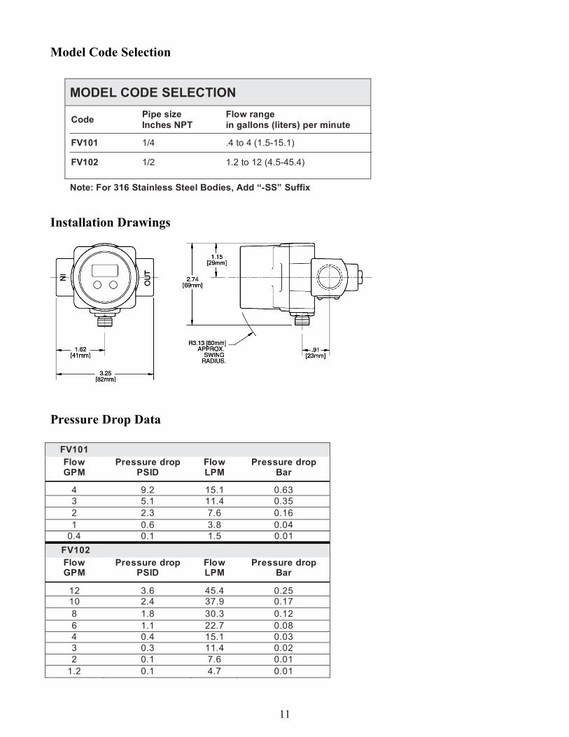
Model Code Selection
Installation Drawings
Pressure Drop Data
FV101 Flow Pressure drop Flow Pressure drop GPM PSID LPM Bar
4 9.2 15.1 0.63
3 5.1 11.4 0.35
2 2.3 7.6 0.16
1 0.6 3.8 0.04
0.4 0.1 1.5 0.01
FV102 Flow Pressure drop Flow Pressure drop GPM PSID LPM Bar
12 3.6 45.4 0.25 10 2.4 37.9 0.17
8 1.8 30.3 0.12
6 1.1 22.7 0.08
4 0.4 15.1 0.03
3 0.3 11.4 0.02
2 0.1 7.6 0.01
1.2 0.1 4.7 0.01
MODEL CODE SELECTION
Code Pipe size Inches NPT
Flow range in gallons (liters) per minute
FV101 1/4 .4 to 4 (1.5-15.1)
FV102 1/2 1.2 to 12 (4.5-45.4)
Note: For 316 Stainless Steel Bodies, Add “-SS” Suffix
12
WARRANTY/DISCLAIMER
OMEGA ENGINEERING, INC. warrants this unit to be free of defects in materials and workmanship fora period of 13 months from date of purchase. OMEGA’s WARRANTY adds an additional one (1)month grace period to the normal one (1) year product warranty to cover handling and shippingtime. This ensures that OMEGA’s customers receive maximum coverage on each product. If the unit malfunctions, it must be returned to the factory for evaluation. OMEGA’s Customer Service Department will issue an Authorized Return (AR) number immediately upon phone or written request. Upon examination by OMEGA, if the unit is found to be defective, it will be repaired or replaced at no charge. OMEGA’s WARRANTY does not apply to defects resulting from any action of the purchaser, including but not limited to mishandling, improper interfacing, operation outside of design limits, improper repair, or unauthorized modification. This WARRANTY is VOID if the unit shows evidence of having been tampered with or shows evidence of having been damaged as a result of excessive corrosion; or current, heat, moisture or vibration; improper specification; misapplication; misuse or other operating conditions outside of OMEGA’s control. Components in which wear is not warranted, include but are not limited to contact points, fuses, and triacs. OMEGA is pleased to offer suggestions on the use of its various products. However, OMEGAneither assumes responsibility for any omissions or errors nor assumes liability for anydamages that result from the use of its products in accordance with information provided byOMEGA, either verbal or written. OMEGA warrants only that the parts manufactured by thecompany will be as specified and free of defects. OMEGA MAKES NO OTHER WARRANTIES ORREPRESENTATIONS OF ANY KIND WHATSOEVER, EXPRESSED OR IMPLIED, EXCEPT THAT OFTITLE, AND ALL IMPLIED WARRANTIES INCLUDING ANY WARRANTY OF MERCHANTABILITYAND FITNESS FOR A PARTICULAR PURPOSE ARE HEREBY DISCLAIMED. LIMITATION OFLIABILITY: The remedies of purchaser set forth herein are exclusive, and the total liability ofOMEGA with respect to this order, whether based on contract, warranty, negligence,indemnification, strict liability or otherwise, shall not exceed the purchase price of thecomponent upon which liability is based. In no event shall OMEGA be liable forconsequential, incidental or special damages. CONDITIONS: Equipment sold by OMEGA is not intended to be used, nor shall it be used: (1) as a“Basic Component” under 10 CFR 21 (NRC), used in or with any nuclear installation or activity; or (2)in medical applications or used on humans. Should any Product(s) be used in or with any nuclearinstallation or activity, medical application, used on humans, or misused in any way, OMEGA assumesno responsibility as set forth in our basic WARRANTY/DISCLAIMER language, and, additionally,purchaser will indemnify OMEGA and hold OMEGA harmless from any liability or damage whatsoeverarising out of the use of the Product(s) in such a manner.
RETURN REQUESTS/INQUIRIES Direct all warranty and repair requests/inquiries to the OMEGA Customer Service Department.BEFORE RETURNING ANY PRODUCT(S) TO OMEGA, PURCHASER MUST OBTAIN AN AUTHORIZEDRETURN (AR) NUMBER FROM OMEGA’S CUSTOMER SERVICE DEPARTMENT (IN ORDER TO AVOIDPROCESSING DELAYS). The assigned AR number should then be marked on the outside of the returnpackage and on any correspondence. The purchaser is responsible for shipping charges, freight, insurance and proper packaging to preventbreakage in transit.
FOR WARRANTY RETURNS, please have the following information available BEFORE contacting OMEGA: 1. Purchase Order number under which the product was PURCHASED, 2. Model and serial number of the product under warranty, and 3. Repair instructions and/or specific problems relative to the product.
FOR NON-WARRANTY REPAIRS, consult OMEGA for current repair charges. Have the following information available BEFORE contacting OMEGA:
1. Purchase Order number to cover the COST of the repair, 2. Model and serial number of the product, and
3. Repair instructions and/or specific problems relative to the product.
OMEGA’s policy is to make running changes, not model changes, whenever an improvement is possible. This affords our customers the latest in technology and engineering. OMEGA is a registered trademark of OMEGA ENGINEERING, INC. © Copyright 2004 OMEGA ENGINEERING, INC. All rights reserved. This document may not be copied, photocopied, reproduced, translated, or reduced to any electronic medium or machine-readable form, in whole or in part, without the prior written consent of OMEGA ENGINEERING, INC.
13
TEMPERATURE
Thermocouple, RTD & Thermistor Probes, Connectors, Panels & Assemblies
Wire: Thermocouple, RTD & Thermistor
Calibrators & Ice Point References
Recorders, Controllers & Process Monitors
Infrared Pyrometers
PRESSURE, STRAIN AND FORCE Transducers & Strain Gages
Load Cells & Pressure Gages
Displacement Transducers
Instrumentation & Accessories
FLOW/LEVEL Rotameters, Gas Mass Flowmeters & Flow Computers
Air Velocity Indicators
Turbine/Paddlewheel Systems
Totalizers & Batch Controllers
pH/CONDUCTIVITY pH Electrodes, Testers & Accessories
Benchtop/Laboratory Meters
Controllers, Calibrators, Simulators & Pumps
Industrial pH & Conductivity Equipment
DATA ACQUISITION Data Acquisition & Engineering Software
Communications-Based Acquisition Systems
Plug-in Cards for Apple, IBM & Compatibles
Datalogging Systems
Recorders, Printers & Plotters
HEATERS Heating Cable
Cartridge & Strip Heaters
Immersion & Band Heaters
Flexible Heaters
Laboratory Heaters
ENVIRONMENTAL MONITORING AND CONTROL Metering & Control Instrumentation
Refractometers
Pumps & Tubing
Air, Soil & Water Monitors
Industrial Water & Wastewater Monitors
pH, Conductivity & Dissolved Oxygen Instruments
M-4116/0808
Where Do I Find Everything I Need for Process Measurement and Control?
OMEGA…Of Course! Shop online at omega.com