Embed Size (px)
Citation preview

omega.com e-mail: [email protected]
For latest product manuals:omegamanual.info
Series FV-200Vortex Shedding Flow Meter
Shop online at
User’s Guide

Servicing North America:U.S.A. : One Omega Drive, P.O. Box 4047 ISO 9001 Certified Stamford, CT 06907-0047
TEL: (203) 359-1660 FAX: (203) 359-7700 e-mail: [email protected]
Canada : 976 Bergar Laval (Quebec) H7L 5A1, Canad a TEL: (514) 856-6928 FAX: (514) 856-6886 e-mail: [email protected] a
For immediate technical or application assistance:U.S.A. and Canada : Sales Service: 1-800-826-6342/1-800-TC-OMEG A ®
Customer Service: 1-800-622-2378/1-800-622-BES T ®
Engineering Service: 1-800-872-9436/1-800-USA-WHEN ®
Mexico: En Espa n ˜o l: (001) 203-359-7803 e-mail: [email protected] FAX: (001) 203-359-7807 [email protected] x
Servicing Europe:Czech Republic: Frystatska 184, 733 01 Karviná, Czech Republic
TEL: + 420 (0) 59 6311899 FAX: + 420 (0) 59 6311114
Toll Free: 0800-1-66342 e-mail: [email protected]
Germany/Austria : Daimlerstrasse 26, D-75392 Deckenpfronn, Germany TEL: +49 (0)7056 9398- 0 FAX: +49 (0)7056 9398-29 Toll Free in Germany: 0800 639 7678 e-mail: [email protected] e
United Kingdom: One Omega Drive, River Bend Technology Centre ISO 9001 Certified Northbank, Irlam, Manchester
M44 5BD United Kingdom TEL: +44 (0)161 777 6611 FAX: +44 (0)161 777 6622 Toll Free in United Kingdom: 0800-488-488 e-mail: [email protected]
OMEGAne t ® Online Service I nternet e-mail omega.com [email protected]
It is the policy of OMEGA Engineering, Inc. to comply with all worldwide safety and EMC/EMIregulations that apply. OMEGA is constantly pursuing certification of its products to the European NewApproach Directives. OMEGA will add the CE mark to every appropriate device upon certification.The information contained in this document is believed to be correct, but OMEGA accepts no liability for anyerrors it contains, and reserves the right to alter specifications without notice.WARNING: These products are not designed for use in, and should not be used for, human applications.

TABLE OF CONTENTS
INTRODUCTION ....................................................................................................................................................... 1DESCRIPTION ......................................................................................................................................................................... 1OPERATING PRINCIPLE ....................................................................................................................................................... 1FLUIDS ....................................................................................................................................................................................... 1
GENERAL INSTALLATION INFORMATION ...................................................................................................... 2FLOW RATE AND RANGE REQUIREMENTS .................................................................................................................. 2PIPING REQUIREMENTS ..................................................................................................................................................... 2BACK PRESSURE .................................................................................................................................................................... 7TEMPERATURE ....................................................................................................................................................................... 7OUTPUTS .................................................................................................................................................................................. 8K-FACTORS .............................................................................................................................................................................. 8
ELECTRICAL INSTALLATIONPOWER ...................................................................................................................................................................................... 8WIRING ...................................................................................................................................................................................... 8
4-20 mA LOOP .................................................................................................................................................................... 80-5 VDC Output ................................................................................................................................................................11Pulse Output .....................................................................................................................................................................11
3 PIN CONNECTION OPTION ..........................................................................................................................................12
RVL (INLINE) SERIES ..............................................................................................................................................14SPECIFICATIONS ..................................................................................................................................................................14FLOW RATES ..........................................................................................................................................................................14MECHANICAL INSTALLATION ........................................................................................................................................15
Dimensions ........................................................................................................................................................................16Temperature Limits .........................................................................................................................................................16Pressure Drop ....................................................................................................................................................................16
RVL (WAFER) SERIES .............................................................................................................................................17SPECIFICATIONS ..................................................................................................................................................................17FLOW RATES ..........................................................................................................................................................................17MECHANICAL INSTALLATION ........................................................................................................................................17
Dimensions ........................................................................................................................................................................20Temperature Limits .........................................................................................................................................................20Pressure Drop ....................................................................................................................................................................21
RVL (TUBE) SERIES .................................................................................................................................................22SPECIFICATIONS ..................................................................................................................................................................22FLOW RATES ..........................................................................................................................................................................22MECHANICAL INSTALLATION ........................................................................................................................................22
Dimensions ........................................................................................................................................................................23Temperature Limits .........................................................................................................................................................24Pressure Drop ....................................................................................................................................................................24
MAINTENANCE .......................................................................................................................................................25TROUBLESHOOTING ............................................................................................................................................25APPENDIX .................................................................................................................................................................26

Page 1
INTRODUCTIONDESCRIPTION
The FV-200 series vortex-shedding fl ow meter is a general-purpose electronic liquid fl ow meter. Three outputs are available. The standard output is a two wire (loop powered) 4-20 mA current. Options for a 0 to 5 VDC or a frequency output proportional to the volumetric fl ow rate are also available. The choice of output must be made at the time of ordering. High accuracy is assured by individual fl ow testing. Since it uses no moving parts, maintenance is minimized.
The FV-200 is available in several types of plastics allowing them to be used in a wide variety of chemical applications.
OPERATING PRINCIPLE
An everyday example of a vortex shedding phenomenon is a fl ag waving in the breeze: the fl ag waves due to the vortices shed by air moving across the fl agpole.
Within the fl ow meter, as a fl uid moves across a tiny strut or “bluff body”, vortices are also shed but on a smaller scale. The vortices form alternately, from one side to the other, causing pressure fl uctuations. These are detected by the crystals in the sensor tube, and are converted to an analog signal or pulse output. The frequency of the vortices is directly proportional to the fl ow. This results in extremely accurate and repeatable measurements with no troublesome moving parts (see fi gure 1).
FLUIDS
Any clean liquid compatible with the plastic material of construction that does not contain signifi cant amounts of fi bers or abrasive materials can be used.
Danger - Do not use with: explosive or fl ammable materials, food or bev-erages, or gaseous fl uids.
Viscosities above 1 cSt will raise the minimum usable fl ow rate (in eff ect reducing range-abil-ity). This eff ect is linear to viscosity. No adjust-ments are required for viscosities up to 2.0 cSt. Liquids with higher viscosities will adversely aff ect the permissible amount and duration of over range fl ow (see table 1).
Viscosity and RangeabilityViscosity Minimum Maximum Flow Range
1 cSt 1 12 12:12 cSt 2 12 6:13 cSt 3 12 4:14 cSt 4 12 3:15 cSt 5 12 2.4:16 cSt 6 12 2:1
TABLE 1
BluffBody
CounterDetector
Detector
FIGURE 1

Page 2
GENERAL INSTALLATION INFORMATION
Prior to installation, the following items should be considered.
1) The vortex transmitter contains electronic circuitry which can be aff ected by high electromagnet-ic or electrostatic fi elds. Care should be taken to locate the installation in an area away from large electrical motors, transformers, or other devices which can produce such interference.
2) Proper grounding is required to eliminate electrical noise which may be present within the fl uid and piping system or in the near vicinity of the vortex transmitter. For non-conductive piping sys-tems, an exterior grounding strap should be used to provide a path to earth ground. For conduc-tive piping systems, a properly grounded pipe will require no additional preparation.
FLOW RATE AND RANGE REQUIREMENTS
Most manufacturers state fl ow range capabilities by publishing the maximum allowed fl ow rates. Then they provide a turndown ratio to determine minimum fl ow rate. To use the turndown ratio, simply divide the maximum rate by the ratio to determine the minimum rate. The FV-200 vortex fl ow meters have a 12:1 turndown ratio at a viscosity of 1 cSt. Higher viscosities will reduce the turndown.
NOTE: The ¼” NPT and ½” Flare meters have a standard turndown ratio of 8:1
PIPING REQUIREMENTS
Turbulence in the pipe line can aff ect the accuracy of most fl ow meters. Sources of turbulence are pumps, valves, or changes-in-direction in the line. To avoid these potential problems, it is standard prac-tice to place the meter a certain distance from the turbulence source. These distances are indicated in Pipe Diameters (PD). For example, 10 PD means place the fl ow meter ten times its inside diameter away from the source of turbulence. Downstream distances between the meter and a valve or a change-in-direction must also be followed.
The best accuracy is achieved with at least 20 PD upstream and 5 PD downstream for FV-200 vortex fl ow meters. If an upstream elbow is closely coupled to another elbow creating a change in plane, 27 PD is required upstream and 10 PD downstream. (see Figure 2, 3, and 4)
When the diameter of the meter is smaller than the pipe line, at least 20 PD of pipe with the same diam-eter as the meter upstream, and 2 PD downstream is needed. Overall, 25 PD of straight run prior to the meter is required (see Figure 5). If there is a plane change in the installation, this IN OUT requirement in-creases to 25 PD upstream (30 overall). The downstream requirement is now 2 PD of pipe with the same diameter as the meter, and a minimum of 5 PD overall of straight run. If there is a valve downstream the usual 10 PD between the meter and a valve is still required.
If the required piping parameters are not met, there will be a reduction in accuracy.
NOTE: Pulsating fl ow will aff ect accuracy (pressure pulses will not.

Page 3
HORIZONTAL FLOW - (Sensing element in vertical orientation)
Confi gurationPiping Requirements
(pipe diameters) Accuracy(full scale)
Repeatability(of point)
Inlet Outlet1 plane change
205
±1.00% 0.25%1 plane change w/outlet valve 102 plane changes
275
2 plane changes w/outlet valve 10
Flow
20 DiaMinimum
5 DiaMinimum
Flow
20 DiaMinimum
10 DiaMinimum
Two PlaneChanges
Flow
5 DiaMinimum
27 DiaMinimum
Flow
10 DiaMinimum
Two PlaneChanges
27 DiaMinimum
FIGURE 2

Page 4
HORIZONTAL FLOW - (Sensing element in horizontal orientation)
Confi gurationPiping Requirements
(pipe diameters) Accuracy(full scale)
Repeatability(of point)
Inlet Outlet1 plane change
205
±1.50% 0.25%1 plane change w/outlet valve 102 plane changes
275
2 plane changes w/outlet valve 10
Flow
20 DiaMinimum
5 DiaMinimum
Flow
20 DiaMinimum
10 DiaMinimum
Two PlaneChanges
Flow
5 DiaMinimum
27 DiaMinimum
Flow
10 DiaMinimum
Two PlaneChanges
27 DiaMinimum
FIGURE 3

Page 5
VERTICAL FLOW - (upward or downward fl ow and sensor in any orientation)
Confi gurationPiping Requirements
(pipe diameters) Accuracy(full scale)
Repeatability(of point)
Inlet Outlet1 plane change
205
±1.00% 0.25%1 plane change w/outlet valve 102 plane changes
275
2 plane changes w/outlet valve 10
Flow
20 DiaMinimum
5 DiaMinimum
Flow
20 DiaMinimum
10 DiaMinimum
Flow
5 DiaMinimum
27 DiaMinimum
Two PlaneChanges
Flow10 Dia
Minimum
Two PlaneChanges
27 DiaMinimum
FIGURE 4

Page 6
25 DiaMinimum
10 DiaMinimum
5 DiaMinimum
2 DiaMinimum
20 DiaMinimum
Flow
25 DiaMinimum
5 DiaMinimum
5 DiaMinimum
2 DiaMinimum
20 DiaMinimum
Flow
Two PlaneChanges
5 DiaMinimum
30 DiaMinimum
5 DiaMinimum
2 DiaMinimum
25 DiaMinimum
Flow
FIGURE 5

Page 7
BACK PRESSURE
Back pressure (the pressure immediately downstream of the meter) must be maintained above a mini-mum level in order to avoid cavitation. For most applications, this may be ignored if the fl ow rate is less than 75% of maximum.
Back Pressure = 2.75 ΔP + 1.25 PV - 14.7Where:
ΔP = Pressure drop in psi at max fl ow PV = Vapor pressure in psia of the liquid at operating temp. (eg. the PV of water at 100 °F is 0.42.) BP = Back pressure (downstream of meter) in psig.
For example the back pressure required for water, at 100 °F (37 °C) in a ½” meter, where the maximum pressure drop is 8 psi, 7.8 psig back pressure is suffi cient. For other liquids, use the following formula to calculate the minimum back pressure.
BP = (2.75 × 8) + (1.25 × 0.42) - 14.7BP = 22 + 0.525 - 14.7BP = 7.825
TEMPERATURE
To protect the internal crystals in each unit, temperature limitations must be adhered to. All permissible operating temperatures are identifi ed by meter and material type. Additionally fl uid temperature will af-fect maximum working pressures. For de-rating information see the maximum fl uid operating pressures for the specifi c fl ow meter model.
OUTPUTS
The FV-200 series meters can be obtained with either an analog output or a rate frequency output. The standard analog output is a 4-20 mA current an optional 0-5 VDC is also available. The analog output can also be re-confi gured in the fi eld using a PC communications cable and programming software which are both available from Omega.
The analog current output varies between 4 mA (0 fl ow) and 20 mA (maximum fl ow). The 0 to 5 VDC analog output is also continuously variable between 0 V (0 fl ow) and 5 V (maximum fl ow).
NOTE: One of the two analog output options (4-20 mA or 0-5 VDC) are hard-ware selected at the factory and can not be changed in the fi eld.
The rate frequency output produces pulses whose frequency is proportional to the fl ow going through the meter. Each meter has a slightly diff erent output frequency which is listed on the calibration sheet that accompanies the meter. Table 2 shows the long term aver-age full scale output frequency for standard size meters.
Meter Size in (mm)
Average Full Scale Frequency (Hz)
Pulse Width (msec)
¼ (6.4) 1055 0.47
½ (12.7) 820 0.61
½ (12.7) 570 0.88
¾ (19.1) 284 1.76
1 (25.4) 292 1.71
1½ (38.1) 144 3.47
2 (50.8) 148 3.38
3 (76.2) 61 8.20
TABLE 2

Page 8
The frequency output option generates a square wave with an amplitude that matches the input power level. The pulse width varies with frequency and is found by using the following formula. The result is in seconds.
PW = 12 x Maximum Frequency (Hz)
K-FACTORS
The K-factor (with regards to fl ow) is the number of pulses that must be accumulated to equal a particu-lar volume of fl uid. Think of each pulse as representing a small fraction of the totalizing unit.
Calibration reports that accompany FV-200 series meters include a nominal K-factor in both gallons and liters. See the sample calibration sheet in the appendix of this manual.
ELECTRICAL INSTALLATIONPOWER
The meter requires an 8 to 28 VDC power supply. The specifi c connections depend upon which output is option is used. See wiring details for the specifi c output option .
NOTE: This instrument requires clean electrical line power. Do not operate this unit on circuits with noisy components (i.e. Fluorescent lights, relays, compressors, variable frequency drives, etc.) Linear power supplies are also much preferable to switching power supplies.
NOTE: The power and output connections share a common ground.
WIRING
4-20 mA LOOP
Connect a twisted pair wire (not provided) to the terminals of the transmitter marked +8-28 VDC and Output. If the twisted pair wire is shielded, do not connect the shield to the transmitter. The shield should be grounded at the receiver only (see fi gure 6). The transmitter is reverse-polarity protected.

Page 9
FIGURE 6
+8-28 VDC
Gnd
Output
Programming
+8-28 VDC
Gnd
Output
8 to 28 VDCOutput POWER
SUPPLY8-28 VDC
4-20 mA
Load
RECEIVER
The receiving equipment must accept industry standard “true two-wire” or “loop powered” 4-20 mA pro-cess transmitter inputs. This means that the receiving equipment, such as a recorder or controller, must supply power for the transmitter along the twisted wire pair. If the receiving equipment does not provide power, a separate power supply, typically 24 VDC and at least 30 mA, must be used, as shown in fi gure 6. There are many brands of receivers which provide 24 VDC for this purpose.
Several receivers may be connected in a series as shown in fi gure 7, but only one should provide power, and all should have isolated inputs. The voltage provided by the receiver must be within the limits shown in the Supply Voltage chart (see fi gure 8).
+8-28 VDC
Gnd
Output
Programming
+8-28 VDC
Gnd
Output
8 to 28 VDCOutput
4-20 mA
Additional Loads
RECEIVER/POWER SUPPLY
RECEIVERRECEIVER
FIGURE 7

Page 10
100200300400500600700800900
10001100
10 128 14 16 18 20 22 24 26 28
Supply Voltage (VDC)
Loop
Loa
d (O
hm's
)
Operate in theShaded Region
Supply Voltage - 8 VDC0.02
= Maximum Loop Resistance
FIGURE 8
To use this fi gure, fi rst add the resistance of all the receivers, indicators, etc., and the wire in the loop. If the wire resistance is unknown, use a value of 50 Ohm for a twisted wire of 1,000 feet or less with a gauge of #22 AWG or heavier.
Find the total load (in ohms) on the left hand side of the chart in fi gure 8 and follow that value horizon-tally until it intersect with the shaded area.
From the intersection point look straight down to where a vertical line would intersect the voltage scale. This is the minimum voltage needed for the transmitter to operate properly under the specifi c load con-ditions.
Example: After checking the specifi cation for all the loads in an application the total amounted to 800 ohms. Following the 800 ohm line in fi gure 9 to the right the intersection point is about ¾ of the way across the chart in fi gure 9.
A vertical line through the intersec-tion point crosses the voltage axis at about 24 VDC so with a load of 800 ohms a standard 24 volt power sup-ply would be used.
100200300400500600700800900
10001100
10 128 14 16 18 20 22 24 26 28
Supply Voltage (VDC)
Loop
Loa
d (O
hm's
)
Operate in theShaded Region
Supply Voltage - 8 VDC0.02
= Maximum Loop Resistance
FIGURE 9

Page 11
Figure 10 and fi gure 11 show typical connections for the 0-5 VDC and pulse output options.
0 - 5 VDC OUTPUT
FIGURE 10
Output
8 to 28 VDCOutputGround
+8-28 VDC
Gnd
0 - 5 VDC
Digital Display
Programming
8-28 VDCPOWERSUPPLY
PULSE OUTPUT
+8-28 VDC
Gnd
Output
8 to OutpGrou
8-28 VDCPOWERSUPPLY
Counter
PulseOutput
FIGURE 11

Page 12
3 PIN CONNECTION OPTION
An optional 3 pin connection is available for when the transmitter/meter combination are to be mount-ed remotely from the power source/receiver. The mating connector is P.N. RF8687000.
+8-28 VDC
Gnd
Output
8 to 28 VDCOutput
White+4-20 mA Input
Black-4-20 mA InputMeter
Electronics
mA
-+
-+Ammeter
8 to 28 VDCPower Supply
+ 4-20 mA Input
-4-20 mA Input
P.N. RF8687000 Connector
FIGURE 12
+8-28 VDC
Gnd
Output
8 to 28 VDCOutputGround
WhiteOutput
Black- Supply Green
Ground
MeterElectronics
-+
8 to 28 VDCPower Supply
WhiteOutput
Black+VGreen
Ground
Counter
P.N. RF8687000 Connector
FIGURE 13

Page 13
White+ 4-20 mA Input
Black- 4-20 mA Input
FIGURE 14

Page 14
FV-200 (INLINE) SERIES
FV-200 (Inline) Specifi cations
Fluid: LiquidsConnection: NPT Female or Butt (PVDF only)
Turndown Ratio:12:1 (½” - 2”) 8:1 (¼”)
Accuracy:±1% of full scale (4-20 mA or 0-5 VDC)±2% of full scale, frequency pulse
Repeatability: ±0.25% of actual fl ow
MaterialsPVC standardCPVC, PVDF optional
Output Signals:
4-20 mA standard0-5 VDC or frequency pulse optional (Push - Pull Driver) 150 mA Sink or Source
Power Supply: 8 to 28 VDCResponse Time 2 seconds minimum, step change in fl ow.Enclosure: Type 4X (IP 66)
FV-200 (Inline) Nominal Flow Rates
Tube Size
(inches)
Minimum Flow
gpm (lpm)
Maximum
Flow
gpm (lpm)
Nominal Full
Scale Frequency
Hz
Weight
lbs (Kg)
¼ 0.6 (2.3) 5 (18.9) 1052 1.5 (0.68)½ 1.3 (4.7) 15 (56.8) 570 1.6 (0.72)¾ 2.1 (7.9) 25 (94.6) 284 1.7 (0.77)1 4.2 (15.8) 50 (189.3) 292 1.8 (0.80)
1½ 8.3 (31.5) 100 (378.5) 144 3.1 (1.40)2 16.7 (63.1) 200 (757.1) 142 2.7 (1.22)
MECHANICAL INSTALLATION
This meter will provide years of accurate service if good fl ow meter installation practices are followed. The fl ow meter should be installed where pipe vibration is minimal.
Observe the upstream piping requirements listed under “Piping requirements”. Upstream valves should not be used to control fl ow rate. They should always be kept fully open. Good quality ball valves with integral unions may be connected directly to the fl ow meter if the valves are fully open during operation. This allows easy isolation and removal of the fl ow meter, should maintenance be required. Cavitation and fl ow rate pulsation will adversely aff ect fl ow meter performance.

Page 15
Diaphragm or piston pumps may not be used. Do not use Tefl on® tape or any kind of pipe dope
when piping.
The simple appearance of the fl ow meter may tempt an installer to handle it as an ordinary nipple. Re-member, it is a precision electronic instrument. Treat it with care.
Do not use excessive force. Mating fi ttings (FNPT) and fl anges should be screwed into meter hand tight; then tighten an additional ½ to ¾ turn.
Always use two wrenches when turning the fl ow meter into a fi tting, one across the fl ats on the fl ow meter end, close to the fi tting, and one on the fi tting.
Do not use tools inside the fl ow meter, as this may damage the vortex sensor, and invalidate the war-ranty.
The fl ow meter may be mounted in any orientation. Three holes, tapped ¼-20 UNC-2B, .375-inch deep, on ¾” centers are provided on the ¾ inch and smaller fl ow meters. These holes may be used (at the user’s discretion) to provide support for the fl ow meter should pipe supports not be practical.
I
ED
B
A
C
F
Cord Grip
NPT/BUTTEND
COVER
CONDUIT ADAPTOR
TERMINAL STRIP
ELECTRONICS MODULE
THREE PIN CONNECTOR
FLOW SENSOR BODY
CORD GRIP
FIGURE 11

Page 16
Size
inches (mm)
FV-200 (Inline) Dimensions PVC/CPVC
A B C D E F I
¼ 3.81 (97) 1.75 (45) 5.25 (133) 2.50 (64) 0.30 (8) 2.88 (73) 3.00 (76)½ 3.81 (97) 1.75 (45) 7.13 (181) 2.50 (64) 0.55 (14) 2.88 (73) 3.00 (76)¾ 3.81 (97) 1.75 (45) 7.63 (194) 2.50 (64) 0.74 (19) 2.88 (73) 3.00 (76)1 3.92 (100) 1.75 (45) 8.03 (204) 2.50 (64) 0.96 (24) 2.88 (73) 3.00 (76)
1½ 3.90 (99) 2.00 (51) 8.37 (213) 2.50 (64) 1.50 (38) 2.88 (73) 3.38 (86)2 4.31 (109) 2.00 (51) 8.37 (213) 2.50 (64) 1.94 (49) 2.88 (73) 3.38 (86)
Size
inches (mm)
FV-200 (Inline) Dimensions PVDF (BUTT Fusion Only)
A B C D E F I
¼ 5.90 (150) 0.63 (16) 4.87 (124) 1.31 (33) 0.30 (8) 2.88 (73) 3.00 (76)½ 5.75 (146) 0.78 (20) 4.87 (124) 1.31 (33) 0.55 (14) 2.88 (73) 3.00 (76)¾ 5.75 (146) 0.94 (24) 4.87 (124) 1.44 (37) 0.74 (19) 2.88 (73) 3.00 (76)1 5.88 (149) 1.19 (30) 5.09 (129) 2.00 (51) 0.96 (24) 2.88 (73) 3.00 (76)
1½ 6.21 (158) 1.50 (38) 6.24 (158) 2.50 (64) 1.50 (38) 2.88 (73) 3.38 (86)2 6.60 (168) 1.88 (48) 6.77 (172) 3.00 (76) 1.94 (49) 2.88 (73) 3.38 (86)
Maximum Fluid
Temperature °F (°C)
FV-200 (Inline) Maximum Operating Pressure PSIG (KPa)
PVC CPVC PVDF
203 (95) Not Recommended Consult Factory Consult Factory
150 (66) Not Recommended 63 (434) 130 (896)100 (38) 93 (641) 120 (827) 150 (1034)70 (21) 150 (1034) 150 (1034) 150 (1034)
.5 2 10 25 100.3 1 5 15 50 200.05
.1
.2
.5
1
2
58
101220
FLOW (GPM)
PRES
SURE
DRO
P (P
SID
)
¼ in
.
½ in
.¾
in.
1 in
. 1
½ in
.2
in.
6002 5 10 20 50 2003.5
5
10
203550
100
200
350500750
FLOW (LPM)
PRES
SURE
DRO
P (M
ILLIBA
R) 1000
30 100 300 800
¼ in
.
½ in
.¾
in.
1 in
. 1
½ in
.2
in.
FIGURE 12

Page 17
FV-200 (WAFER) SERIES
FV-200 (Wafer) Specifi cations
Fluid: LiquidsConnection: WaferTurndown Ratio: 12:1
Accuracy:±1% of full scale (4-20 mA or 0-5 VDC)±2% of full scale, frequency pulse
Repeatability: ±0.25% of actual fl ow
MaterialsPVC standardCPVC, Polypropylene, PVDF optional
Output Signals:
4-20 mA standard0-5 VDC or frequency pulse optional (Push - Pull Driver) 150 mA Sink or Source
Power Supply: 8 to 28 VDCResponse Time 2 seconds minimum, step change in fl ow.Enclosure: Type 4X (IP 66)
FV-200 (Wafer) Nominal Flow Rates
Tube Size
(inches)
Minimum Flow
gpm (lpm)
Maximum
Flow
gpm (lpm)
Nominal Full
Scale Frequency
Hz
Weight
lbs (Kg)
½ 1.3 (4.7) 15 (56.8) 570 0.8 (0.36)¾ 2.1 (7.9) 25 (94.6) 284 0.9 (0.41)1 4.2 (15.8) 50 (189.3) 292 1.1 (0.50)
1½ 8.3 (31.5) 100 (378.5) 144 1.7 (0.77)2 16.7 (63.1) 200 (757.1) 148 2.6 (1.17)3 25.0 (94.6) 300 (1136) 61 4.8 (2.16)
MECHANICAL INSTALLATION
The FV-200 (Wafer) series transmitters are designed with wafer style fl ow bodies, which mount easily between standard ANSI style pipe fl anges.
Observe the upstream piping requirements listed under “Piping requirements”. Upstream valves should not be used to control fl ow rate. They should always be kept fully open. Good quality ball valves with integral unions may be connected directly to the fl ow meter if the valves are fully open during operation. This allows easy isolation and removal of the fl ow meter, should maintenance be required. Cavitation and fl ow rate pulsation will adversely aff ect fl ow meter performance.

Page 18
Diaphragm or piston pumps may not be used. Do not use Tefl on® tape or any kind of pipe dope vawhen piping. For fl anged meters, do not allow gaskets to protrude into the fl ow stream.
The following steps will insure proper installation and operation.
1) A uniform fl ow profi le is required to assure proper vortex shedding. This requires a non-pulsating fl ow along with the proper length of straight pipe run before and after the transmitter. Figures
2,3,4 and 4 shows the proper piping requirements and dimensions.
FLANGE SIZE RECOMMENDED TORQUE
½ -1½” 10-15 ft. Ibs.2-3” 20-30 ft. Ibs.
2) Flanges are to be spaced to accommodate the width of the fl ow body. Dimensions are listed on page 20.
3) Align the fl ow body centered with respect to fl anges and gaskets, insert threaded rods, retaining nuts and lock washers.
4) Install all retaining nuts hand tight, and then uniformly tighten the nuts in an alternating se-quence, diametrically opposed to each other. Uniform stress across the fl ange will prevent leak-age at the gasket. Torque ratings are listed below.
5) The use of grounding rings is recommended when metal pipes are used in conjunction with this meter. See fi gure 13

Page 19
GroundingRings
FIGURE 13

Page 20
C
E
D
A
B
Cord Grip
TERMINAL STRIP
ELECTRONICS MODULE
THREE PIN CONNECTOR
FLOW SENSOR BODY
COVER
CONDUIT ADAPTOR
CORD GRIP
FIGURE 14
Size inchesFV-200 (Wafer) Dimensions PP/PVC/CPVC/PVDF
A B C D E
½ 5.85 (149) 0.78 (20) 2.03 (52) 1.75 (45) 2.88 (73)¾ 5.90(150) 0.94 (24) 2.03 (52) 1.75 (45) 2.88 (73)1 5.69 (145) 1.19 (30) 2.25 (57) 1.75 (45) 2.88 (73)
1½ 6.00 (152) 1.50 (38) 2.63 (67) 1.75 (45) 2.88 (73)2 6.37 (162) 1.88 (48) 3.22 (82) 1.75 (45) 2.88 (73)3 6.88 (175) 2.50 (64) 4.25. (108) 1.75 (45) 2.88 (73)
FV-200 (Wafer) Standard Specifi cations
Maximum Fluid
Temperature °F (°C)
Maximum Operating Pressure PSIG (KPa)
PVC CPVC Polypropylene PVDF
203 (95) Not Recommended Consult Factory Not Recommended Consult Factory150 (66) Not Recommended 63 (434) 90 (621) 130 (896)100 (38) 100 (690) 120 (827) 130 (896) 150 (1034)70 (21) 150 (1034) 150 (1034) 150 (1034) 150 (1034)

Page 21
FV-200 (Wafer) High Pressure Specifi cations
Maximum Fluid
Temperature °F (°C)
Maximum Operating Pressure PSIG (KPa)
PVC CPVC Polypropylene PVDF
203 (95) Not Recommended Not Recommended Not Recommended Consult Factory150 (66) Consult Factory Consult Factory 90 (621) 300 (2068)100 (38) Consult Factory Consult Factory 130 (896) 400 (2750)70 (21) Consult Factory Consult Factory 150 (1034) 400 (2750)
.5 2 10 25 100 300.3 1 5 15 50 200.05
.1
.2
.5
1
2
58
101220
FLOW (GPM)
PRES
SURE
DRO
P (P
SID
)
1½ in
.
1 in
.
2 in
.
3 in
.
¾ in
.
½ in
.
6002 5 10 20 50 2003.5
5
10
203550
100
200
350500750
FLOW (LPM)
PRES
SURE
DRO
P (M
ILLIBA
R) 1000
30 100 300 8001200
1/2
in. 3/
4 in
.1
in.
1½
in.
2 in
.3
in.
FIGURE 15

Page 22
FV-200 (TUBE) SERIES
FV-200 (Tube) Specifi cations
Fluid: LiquidsConnection: Tube (Flare end)
Turndown Ratio:12:1 (¾”, 1”) 8:1 (½”)
Accuracy:±1% of full scale (4-20 mA or 0-5 VDC)±2% of full scale, frequency pulse
Repeatability: ±0.25% of actual fl ow
MaterialsPVC standardCPVC, Polypropylene, PVDF optional
Output Signals:
4-20 mA standard0-5 VDC or frequency pulse optional (Push - Pull Driver) 150 mA Sink or Source
Power Supply: 8 to 28 VDCResponse Time 2 seconds minimum, step change in fl ow.Enclosure: Type 4X (IP 66)
FV-200 (Tube) Nominal Flow Rates
Tube Size
(inches)
Minimum Flow
gpm (lpm)
Maximum Flow
gpm (lpm)
Weight
lbs (Kg)
½ 0.6 (2.3) 5 (18.9) 1.5 (0.68)¾ 1.3 (4.7) 15 (56.8) 1.6 (0.72)1 2.1 (7.9) 25 (94.6) 1.7 (0.77)
MECHANICAL INSTALLATION
This meter will provide years of accurate service if good fl ow meter installation practices are followed. The fl ow meter should be installed where pipe vibration is minimal.
Observe the upstream piping requirements listed under “Piping requirements”. Upstream valves should not be used to control fl ow rate. They should always be kept fully open. Good quality ball valves with integral unions may be connected directly to the fl ow meter if the valves are fully open during operation.
This allows easy isolation and removal of the fl ow meter, should maintenance be required. Cavitation and fl ow rate pulsation will adversely aff ect fl ow meter performance.
Diaphragm or piston pumps may not be used. Do not use Tefl on® tape or any kind of pipe dope when piping.

Page 23
The simple appearance of the fl ow meter may tempt an installer to handle it as an ordinary nipple. Re-member, it is a precision electronic instrument. Treat it with care.
1) To install a fl are fi tting, fi rst remove any burrs from the pipe ends, then slide the fl are nut onto the pipe. Push it back far enough so that it will be out of the way when you use the fl aring tool.
2) Clip the pipe in the fl aring tool, keeping the end fl ush with the face of the tool. 3) Slowly turn the handle on the tool until it bottoms out. 4) Unscrew the handle and remove the tool to check the quality of the fl are. (If the fl are isn’t smooth
or even the fi rst time, cut off the end with your pipe cutter, and try the technique again.) 5) Line up and tighten the nut and fl ared pipe to the fi tting body. Make the connection as tight but
not so tight as to distort the fl ow meter body.
Always use two wrenches when turning a fi tting onto the fl ow meter, one across the fl ats on the fl ow meter end, close to the fi tting, and one on the fi tting.
Do not use tools inside the fl ow meter, as this may damage the vortex sensor, and invalidate the war-ranty.
The fl ow meter may be mounted in any orientation.
C
B
A
TERMINAL STRIP
ELECTRONICS MODULE
THREE PIN CONNECTOR
FLOW SENSOR BODY
COVER
CONDUIT ADAPTOR
CORD GRIP
FIGURE 16
FV-200 (Tube) Dimensions
Tube Size (inches) A B) C
½ 1.31 (33.3) 6.25 (158.8) 4.87 (123.7)¾ 1.31 (33.3) 6.25 (158.8) 4.66 (118.4)1 1.44 (36.6) 6.59 (167.4) 5.42 (137.7)
Page 24
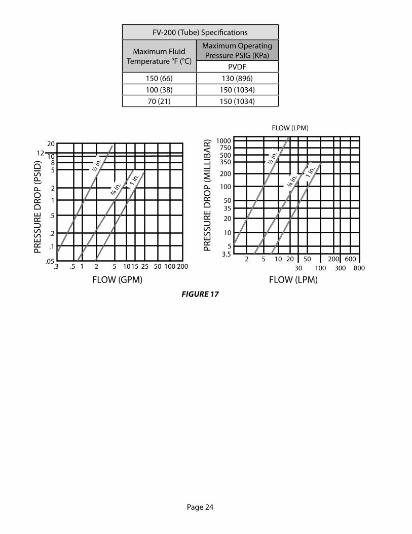
FV-200 (Tube) Specifi cations
Maximum Fluid Temperature °F (°C)
Maximum Operating Pressure PSIG (KPa)
PVDF150 (66) 130 (896)100 (38) 150 (1034)70 (21) 150 (1034)
.5 2 10 25 100.3 1 5 15 50 200.05
.1
.2
.5
1
2
58
101220
PRES
SURE
DRO
P (P
SID
)
½ in
.
1 in
.
¾ in
.
FLOW (GPM)
FLOW (LPM)
6002 5 10 20 50 2003.5
5
10
203550
100
200
350500750
FLOW (LPM)
PRES
SURE
DRO
P (M
ILLIBA
R) 1000
30 100 300 800
1 in
.
½ in
.
¾ in
.FIGURE 17

Page 25
MAINTENANCE
This fl ow meter requires no maintenance in normal service if properly installed. If the fl ow tube should become clogged with debris, it will be necessary to remove the meter from service for cleaning. Signifi -cant clogging will often result in high (up to 20%) and/or erratic output. Do not stick tools into the tube, as this may permanently damage the vortex sensor. The vortex sensor can not be repaired in the fi eld. To clean the fl ow tube, run hot (up to 160 °F) soapy water into the downstream end of the fl ow tube. Large objects jammed against the bluff body maybe dislodged by lightly tapping the upstream end of the fl ow tube against a fi rm surface.
WARNING: Do not remove vortex meter during operation. Always disconnect primary power source before inspection of service. Do not tap the fl ow tube so hard that the threads, on threaded units, become damaged
A schedule of maintenance checks should be determined based upon environmental conditions and frequency of use. Inspect the meter at least once a year.
The inspection should consist of performing visual, electrical, and mechanical checks on all components.1) Visually check for evidence of overheating by noting discoloration of wires or other components.2) Check for damaged or worn parts, especially the bluff body, or indications of corrosion.3) Check for tight , clean electrical connections and that the device is operating properly.
TROUBLESHOOTING
If diffi culty is encountered, locate the symptom most likely present and follow the appropriate instruc-tions.
CURRENT LOOP
SYMPTOM - NO CURRENT OUTPUT
1) Place a DC voltmeter across the two terminal block screws. With the electronics module powered there must be at least 8 VDC present. If there is less than 8 VDC, but more than 0 VDC, check the power source for suffi cient voltage to drive the loop, as shown on page 10, in Figure 8. If there is 0 VDC present check for a broken wire or connector in the loop.
2) Check for the proper polarity of the current loop connections.3) Make sure the receiving device is confi gured to provide (source) current to the electronics mod-
ule.
SYMPTOM - ZERO FLOW INDICATION (4 mA IN LOOP).
1) Check that the fl ow is greater than the minimum specifi ed for the particular size fl ow meter in use. If the fl ow rate is too low, replace the fl ow meter with the proper size fl ow meter.
2) If the fl ow rate is suffi cient, partially remove the electronic module. Check that the three pin con-nector that connects the electronics module to the fl ow transducers is positively connected (See
Figure 18). If it is disconnected, align and insert the connector on to the bottom of the electronics module.

Page 26
SYMPTOM - Erratic Flow Indication
Check that there is at least 8 VDC present across the two terminal block screws.
Check for material clogging the fl ow meter and in the upstream piping.
Check for erosion of the bluff body by sighting down the meters bore. Erosion or damage to the bluff body will cause erratic readings and compromise accuracy. If the erosion continues, the fl ow meter will need to be periodically replaced.
Check upstream piping to assure that the required piping is used. (See the piping requirements specifi -cations starting on page 2 for this information.)
Check for pipe vibration. Normal amounts of pipe vibration are easily tolerated. In addition to this, the transmitter module contains a highly eff ective active fi lter that rejects false signals caused by pipe vibra-tion. This fi lter is most eff ective under fl owing conditions. If vibration is causing the meter to indicate fl ow when the fl ow is stopped it will most likely not cause error under fl owing conditions. The false fl ow indication may be ignored, or the pipe may be restrained by fi rm clamps, or the noise adjustment may be readjusted. Be sure to read the noise adjustment instructions.
Check for electrical noise. Under some conditions there can be high common mode AC noise present between the fl uid and the power supply ground. The fl ow meter is designed to reject up to 50 volts of AC common mode noise without loss of accuracy. If metal piping is used, place a ground strap on the pipe on both sides of the fl ow meter (the fl ow meter is made of non-conductive plastic) and connect them both to the one point where the loop is grounded (see wiring diagrams starting on page 9). If plastic pip-ing is used, a grounding orifi ce should be used. The transmitter module contains a highly eff ective active fi lter that will reject false signals due to high common mode voltage. This fi lter is most eff ective under fl owing conditions. If a false indication of fl ow is encountered at zero fl ow, it will probably not cause error under fl owing conditions. In addition, the noise adjustment may be used, but it will reduce the ability of the fl ow meter to measure low fl ow rates. See the noise adjustment instructions before attempting to make this adjustment.
OVER-STRESSED SENSOR
If the maximum permitted fl ow rate of 125% of Recommended capacity (100% of HT meters) is exceed-ed, it is possible to over-stress the sensor.

Page 27
APPENDIXCALIBRATION CERTIFICATE SAMPLE
Calibration Report
Unit Under Test (UUT) Information: Master Meter:
Description: ¾ ” In-Line NPT End Flow Meter Std uncertainty: ±0.25%Model Number: FV-201 Traceability No: 30400/31801Serial Number: 99999 Model No: FT8-8N EXW-LEG-5/FT-16 NEXW-LEG-1Sensor Type: Vortex Shedding Serial No: 806890/16011903Output type: 0-5VMinimum Flow: 2.1 GPM 7.9 LPM Customer Information:
Maximum Flow: 25 GPM 94.6 LPM Customer Name:
Calibration Date: October 24, 2007 Customer No.:
Calibration Interval: 12 Months Order No.:
Cal. Liquid: WaterAmbient Temperature: 71.74 °FAmbient Humidity: 31.39 %RHLinear Points: 5
UUT Calibration Data Table In GPM:
Flow Standard
Actual GPM
UUTHz
UUT Temp °F
Visc.cSt
UUT F/V Hz/cSt
UUT K CYC/GAL
(Hz*60)/NK GPM
Linear COEFF.
Raw Err % FS
Calc.0-5V
Meas. 0-5V
Output Err % FS
1 25.00 100.000 72.00 0.949 105.406 240.00 24.57 1.0174 1.71 5.000 5.000 0.00
1 18.00 75.000 72.00 0.949 79.055 250.00 18.43 0.9767 -1.71 3.600 3.680 0.40
1 12.00 50.000 72.00 0.949 52.703 250.00 12.29 0.9767 -1.14 2.400 2.420 0.10
1 6.00 25.000 72.00 0.949 26.352 250.00 6.14 0.9767 -0.57 1.200 1.200 0.00
1 2.10 10.000 72.00 0.949 10.541 285.71 2.46 0.8547 -1.43 0.420 0.420 0.00
Nominal K (NK) 244.186
UUT Calibration Data Table In LPM:
Flow Standard
Actual GPM
UUTHz
UUT Temp °F
Visc.cSt
UUT F/V Hz/cSt
UUT K CYC/GAL
(Hz*60)/NK GPM
Linear COEFF.
Raw Err % FS
Calc.0-5V
Meas. 0-5V
Output Err % FS
1 94.64 100.000 72.00 0.949 105.406 63.40 93.01 1.0174 1.71 5.000 5.000 0.00
1 68.14 75.000 72.00 0.949 79.055 66.04 69.76 0.9767 -1.71 3.600 3.680 0.40
1 45.42 50.000 72.00 0.949 52.703 66.04 46.51 0.9767 -1.14 2.400 2.420 0.10
1 22.71 25.000 72.00 0.949 26.352 66.04 23.25 0.9767 -0.57 1.200 1.200 0.00
1 7.95 10.000 72.00 0.949 10.541 75.48 9.30 0.8547 -1.43 0.420 0.420 0.00
Nominal K (NK) 64.507
Status: PASS
Meter Accuracy (of FS): ± 0.4 %
Average Calib. Temperature : 72 F
Average Calib. Specifi c Gravity : 1 Calibrated By: Ramon Benedict
Average Calib. Viscosity : 0.95 cSt
Flow Direction : Forward Certifi ed By: Larry Perez
Calibrations are performed using standards traceable to National Institute of Standards and Technology.The equipment and calibration procedures complies with ISO 9001
Sampleee
mmp
mpp
LCOE
.57 1.01741.0174
18.4318.43 0.97670.9767
0 12.2929 0.97670.9767 -1
250.00 6.146.14 0.97670
285.711 2.46.46 0.8547
Nominal K (NK) 244.186al K (NK) 244.1
SaSammmmp
mp
sc.cSt
UUT F/V T F/V Hz/cStHz/cSt
UUT K UUT KCYC/GALC/
(Hz*
0.9490.949 105.406105.406 63.40
.00 0.9490.949 79.05579.055
0.9490.949 52.703
0.9490.949 26.
0.9490

Page 28
NOTES

Page 29
NOTES

Page 30
NOTES

Page 31
WARRANTY/DISCLAIMEROMEGA ENGINEERING, INC. warrants this unit to be free of defects in materials and workmanship for aperiod of 13 months from date of purchase. OMEGA’s WARRANTY adds an additional one (1) monthgrace period to the normal one (1) year product warranty to cover handling and shipping time. Thisensures that OMEGA’s customers receive maximum coverage on each product. If the unit malfunctions, it must be returned to the factory for evaluation. OMEGA’s Customer ServiceDepartment will issue an Authorized Return (AR) number immediately upon phone or written request.Upon examination by OMEGA, if the unit is found to be defective, it will be repaired or replaced at nocharge. OMEGA’s WARRANTY does not apply to defects resulting from any action of the purchaser,including but not limited to mishandling, improper interfacing, operation outside of design limits, improper repair, or unauthorized modification. This WARRANTY is VOID if the unit shows evidence of having been tampered with or shows evidence of having been damaged as a result of excessive corrosion;or current, heat, moisture or vibration; improper specification; misapplication; misuse or other operatingconditions outside of OMEGA’s control. Components in which wear is not warranted, include but are not limited to contact points, fuses, and triacs.OMEGA is pleased to offer suggestions on the use of its various products. However, OMEGA neither assumes responsibility for any omissions or errors nor assumes liability for anydamages that result from the use of its products in accordance with information provided byOMEGA, either verbal or written. OMEGA warrants only that the parts manufactured by thecompany will be as specified and free of defects. OMEGA MAKES NO OTHER WARRANTIES OR REPRESENTATIONS OF ANY KIND WHATSOEVER, EXPRESSED OR IMPLIED, EXCEPT THAT OFTITLE, AND ALL IMPLIED WARRANTIES INCLUDING ANY WARRANTY OF MERCHANTABILITYAND FITNESS FOR A PARTICULAR PURPOSE ARE HEREBY DISCLAIMED. LIMITATION OF LIABILITY: The remedies of purchaser set forth herein are exclusive, and the total liability of OMEGA with respect to this order, whether based on contract, warranty, negligence, indemnification, strict liability or otherwise, shall not exceed the purchase price of the component upon which liability is based. In no event shall OMEGA be liable for consequential, incidental or special damages.CONDITIONS: Equipment sold by OMEGA is not intended to be used, nor shall it be used: (1) as a “BasicComponent” under 10 CFR 21 (NRC), used in or with any nuclear installation or activity; or (2) in medicalapplications or used on humans. Should any Product(s) be used in or with any nuclear installation oractivity, medical application, used on humans, or misused in any way, OMEGA assumes no responsibilityas set forth in our basic WARRANTY/DISCLAIMER language, and, additionally, purchaser will indemnifyOMEGA and hold OMEGA harmless from any liability or damage whatsoever arising out of the use of theProduct(s) in such a manner.
RETURN REQUESTS/INQUIRIESDirect all warranty and repair requests/inquiries to the OMEGA Customer Service Department. BEFORERETURNING ANY PRODUCT(S) TO OMEGA, PURCHASER MUST OBTAIN AN AUTHORIZED RETURN(AR) NUMBER FROM OMEGA’S CUSTOMER SERVICE DEPARTMENT (IN ORDER TO AVOIDPROCESSING DELAYS). The assigned AR number should then be marked on the outside of the returnpackage and on any correspondence.The purchaser is responsible for shipping charges, freight, insurance and proper packaging to preventbreakage in transit.
FOR WARRANTY RETURNS, please have the following information available BEFORE contacting OMEGA:1. Purchase Order number under which the product
was PURCHASED,2. Model and serial number of the product under
warranty, and3. Repair instructions and/or specific problems
relative to the product.
FOR NON-WARRANTY REPAIRS, consult OMEGAfor current repair charges. Have the followinginformation available BEFORE contacting OMEGA:1. Purchase Order number to cover the COST
of the repair,2. Model and serial number of the product, and3. Repair instructions and/or specific problems
relative to the product.
OMEGA’s policy is to make running changes, not model changes, whenever an improvement is possible. This affordsour customers the latest in technology and engineering.OMEGA is a registered trademark of OMEGA ENGINEERING, INC.© Copyright 2008 OMEGA ENGINEERING, INC. All rights reserved. This document may not be copied, photocopied,reproduced, translated, or reduced to any electronic medium or machine-readable form, in whole or in part, without theprior written consent of OMEGA ENGINEERING, INC.

M-4503/1108
Where Do I Find Everything I Need for Process Measurement and Control?
OMEGA…Of Course!Shop online at omega.com SM
TEMPERATURE� � Thermocouple, RTD & Thermistor Probes, Connectors, Panels & Assemblies � � Wire: Thermocouple, RTD & Thermistor � � Calibrators & Ice Point References � � Recorders, Controllers & Process Monitor s � � Infrared Pyrometers
PRESSURE, STRAIN AND FORCE� � Transducers & Strain Gage s � � Load Cells & Pressure Gage s � � Displacement Transducers � � Instrumentation & Accessories
FLOW/LEVEL� � Rotameters, Gas Mass Flowmeters & Flow Computers � � Air Velocity Indicator s � � Turbine/Paddlewheel Systems � � Totalizers & Batch Controllers
pH/CONDUCTIVITY� � pH Electrodes, Testers & Accessories � � Benchtop/Laboratory Meters � � Controllers, Calibrators, Simulators & Pumps � � Industrial pH & Conductivity Equipment
DATA ACQUISITION� � Data Acquisition & Engineering Softwar e � � Communications-Based Acquisition Systems � � Plug-in Cards for Apple, IBM & Compatibles � � Datalogging Systems � � Recorders, Printers & Plotters
HEATERS� � Heating Cabl e � � Cartridge & Strip Heaters � � Immersion & Band Heaters � � Flexible Heaters � � Laboratory Heaters
ENVIRONMENTALMONITORING AND CONTROL� � Metering & Control Instrumentatio n � � Refractometers � � Pumps & Tubing � � Air, Soil & Water Monitor s � � Industrial Water & Wastewater Treatment � � pH, Conductivity & Dissolved Oxygen Instrument s