Embed Size (px)
Citation preview
Vortex-Pro Robotic Pool Cleaner
Owner's Manual
H050
3800
Rev
A
WARNINGFOR YOUR SAFETY - For anything other than the routine cleaning and maintenance described in this manual, this product must be repaired by a pool technician who is licensed and qualified in pool equipment by the jurisdiction in which the product will be installed where such state or local requirements exist. In the event no such state or local requirement exists, the pool technician must be a professional with sufficient experience in pool equipment installation and maintenance so that all of the instructions in this manual can be followed exactly. Improper installation and/or operation will void the warranty.

Table of Contents
Section 1. Important Safety Instructions ........ 3
Section 2. Cleaner Specifications ................... 42.1 GeneralSpecifications ....................................... 4
Section 3. Assembly ......................................... 43.1 Unpacking .......................................................... 43.2 AssemblingtheTransportCaddy ....................... 53.3 ConnectingtheControlboxtoCaddy ................ 73.4 ConnectingFloatingCabletoControlBox ......... 7
Section 4. Operation ......................................... 84.1 SubmergingtheCleaner .................................... 84.2 TheVX554WDCleanerControlbox ............... 104.3 StartingtheCleaner ......................................... 104.4 StoppingtheCleaner
andRemovingfromthePool .............................114.5 OperatingtheCleanerwith
theRemoteControl ..........................................114.6 SynchronizingtheRemoteControl ................... 124.7 StoringtheCleaner ......................................... 12
Section 5. Programming the Cleaner ............. 135.1 DisplayingCurrentDayandTime ..................... 135.2 ChangingtheClockDayandTime ................... 135.3 ChangingDefaultCleaningTimes .................... 135.4 ProgrammingCleaningCycles ......................... 145.5 CancelingCleaningCycles .............................. 14
Section 6. Cleaning and Maintenance .......... 156.1 CleaningtheFilterCanister .............................. 156.2. CordTangling ................................................... 166.3 ReplacingtheBrushes ..................................... 176.4 ReplacingtheTyres .......................................... 18
Section 7. Spare Parts .................................... 19
Section 8. Troubleshooting ........................... 208.1 ViewingCleanerStatusInformation
forTroubleshooting ........................................... 208.2 ControlBoxErrorCodes .................................. 218.3 GeneralTroubleshooting .................................. 22
Section 9. Conformity ..................................23
THANKYOUFORPURCHASINGTHISROBOTICPOOLCLEANERBYZODIAC®.
YOURCLEANERHASBEENDESIGNEDANDMANUFACTUREDTOBEEASILYINSTALLEDANDTOPROVIDELOWMAINTENANCEOPERATION.AWARRANTYCARDISSUPPLIEDINTHEBOX.PLEASEGOTO www.zodiac.co.zaTOREGISTERFORWARRANTY.
Takingthesestepswillhelpensurepromptwarrantyservice,shoulditberequired.Ifserviceisrequired,please contactyouroriginaldealer.Iftheoriginaldealerdoesnotperformwarrantyservice,pleasevisit www.zodiac.co.zatolocateanindependentservicecompanynearyou.Ifyouareunabletolocateaservice company,pleasecallourCustomerCareLineat086088POOL(0860887665).
H0503800_REV A2

Section 1. Important Safety Instructions Congratulations on purchasing the Zodiac® robotic cleaner. Please read through the entire manual before installing the cleaner. Your cleaner must be installed and operated as specified.
READ AND FOLLOW ALL INSTRUCTIONS
SAVE THESE INSTRUCTIONS
WARNINGFailure to comply with the following warnings can result in permanent injury, electrocution or death.
PREVENT ELECTRICAL SHOCKToreduceriskofelectricalshock:
• ThecleaneristobeinstalledinaccordancewiththerelevantrequirementsoftheSouthAfricanwiringrules,OccupationalHealthandSafetyAct,1993(Actno.85of1993)scheduleelectricalinstallationregulations.Alsorefertotheinstallationinstructionsrelatingtotheswimmingpoolequipmentforwhichthecleanerwillbeanintegralpart.ThecleaneristobesuppliedthroughaResidualCurrentDevice(EarthLeakage)witharatedresidualoperatingcurrentof30mA.
• Donotenterpoolwhiletheroboticcleanerisinwater.
• Donotburycord.Locatecordsoastopreventitfrombeingdamagedbylawnmowers,hedgetrimmersandotherequipment.
• Toreducetheriskofelectricalshock,donotusetheroboticcleanerorcontrolboxifthecordiswornordamaged.ContactZodiacCustomerCareLineat086088POOL(0860887665)immediatelyforproperservicingandreplacementofthedamagedcord.
• Doubleinsulation—Forcontinuedprotectionagainstpossibleelectricshock,useonlyidenticalreplacementpartswhenservicing.Donotattemptrepairoftheroboticcleaner,controlbox,powercord,orfloatingcable.
• Useonlythepowersupplyprovidedwiththeproduct.
• NEVEROPENControlbox.
• DONOTUSEANEXTENSIONCORDTOCONNECTTHEUNITTOELECTRICSUPPLY;PROVIDEAPROPERLYLOCATEDRCDPROTECTEDPOWEROUTLET.THECONTROLBOXSHOULDBEPLACEDNEARTHERCDPROTECTEDPOWEROUTLETPOINT.
PREVENT CHILD INJURY AND DROWNING
• Toreducetheriskofinjury,donotpermitchildrenorpersonswithreducedphysical,sensoryormentalcapabilities,orlackofexperienceandknowledgetooperatethisproduct.
• Donotletanyone,especiallysmallchildren,sit,step,lean,orclimbonanyequipmentinstalledaspartofyourpool’soperationalsystem.
CAUTIONFailure to comply with the following warnings could cause damage to pool equipment or personal injury.
• Theroboticcleanermustbeinstalledandoperatedasspecified.
• Thisproductisintendedforusewithpermanently-installedpools.Donotusewithstorablepools.Apermanently-installedpoolisconstructedinoronthegroundorinabuildingsuchthatitcannotbereadilydisassembledforstorage.Astorablepoolisconstructedsothatitiscapableofbeingreadilydisassembledforstorageandreassembledtoitsoriginalintegrity.
• Thisproductisunsuitableforuseinvinylpools.
• Itisnotrecommendedthatyoukeepyourcleanerinthepoolforunecessaryperiodsoftimewhennotrunning.
• Cleanthefiltercanisteraftereachuse.
• Do not use the product in your pool if the water temperature is above 35˚ C (95˚ F) or below 13˚ C (55˚ F).
3 H0503800_REV A

Section 2. Cleaner Specifications2.1 General SpecificationsThe general specifications for the cleaner are as follows:
x 2
A
B C Dx 2x 2
E x 2
F
GH
I
Figure 1. Transport Caddy Assembly Components (A) handle frame
(B) support blocks (x 2) (C) wheels (x 2) (D) wheel locking clips (x 2) (E) wheel axle / hubcap (x 2) (F) base unit (G) cleaner hook (h) caddy handle (I) remote control hook
When unpacking the cleaner and its components:• Check to make sure each component is in the box.• Check cleaner and components for damage during
transport.• If there are any missing parts or damage, contact
Zodiac® at 0860 88 POOL (0860 887 665).
Control box supply voltage
220-240VAC,50Hz
Supply voltage 30VDC
Installed load 150Wmax
Cable length 21m
Cleaner size (WxDxH)
43x48x27cm
Weight of Cleaner 9.5kg
Packed weight 19kg
Filtration All-purposefiltercanister
Cycle lengths Variableprogrammingforcleaningfloor,walls,andwaterline. From1.5-3.0hours.
Filter Canister 200microns
The cleaner is a double-insulated product. A double-insulated electrical appliance is one which has been designed in such a way that it does not require a safety connection to ground. The basic requirement for double-insulation is that no single failure can result in dangerous voltage becoming exposed so that it might cause an electric shock and that this is achieved without relying on an earthed (grounded) metal casing. This is achieved by having two (2) layers of insulating material surrounding live parts or by using reinforced insulation. Therefore, devices having double-insulated construction, such as this cleaner, do not utilize a grounded (three-prong) cord/plug.
Section 3. Assembly3.1 UnpackingThe packaging should contain the following items:
• Robotic cleaner• Control box• Remote Control• Transport and storage caddy assembly components• Quick Start Guide• Warranty Card
H0503800_REV A4

3.2 Assembling the Transport Caddy1. Unscrew the handnut from the base unit
(Figure 2).
Figure 2. Remove Handnut from Base Unit2. Insert the metal handle frame tubing into the
base unit with notch end at the top, then rotate so the bends are away from you. (Figure 3)
3. Push base unit down (Figure 3) so the metal handle frame is seated in the recess on the underside of the base.
Figure 3. Connect Metal Frame to Base Unit4. Slide the handnut over the tube and twist to
tighten onto base unit (Figure 4).
Figure 4. Twist Handnut to Secure Frame5. Snap two (2) support blocks into place
(Figure 5).
6. Slide axle and hubcap piece through center of wheel and attach to base unit. Snap locking clip into place to secure wheel. Repeat to attach both wheels (Figure 5).
Figure 5. Snap in Support Blocks and Attach Wheels
7. Slide the control box base / caddy handle attachment down over the metal tubing until it snaps into place. (See Figure 6).
5 H0503800_REV A

Figure 8. Snap Remote Control Holder into Place
Figure 9. Fully Assembled Transport Caddy
Figure 6. Attach Caddy Handle8. Align cleaner hook pins with the top holes in
the handle tube and snap into place (Figure 7).
Figure 7. Snap Cleaner Hook into Place
9. Locate pin on the remote control holder and align it with the receptacle on the handle of the caddy to attach the remote control box to caddy (Figure 8).
H0503800_REV A6

3.4 Connecting Floating Cable to Control Box
WARNINGFailuretocomplywiththefollowingwarningscanresultinpermanentinjury,electrocutionordrowning.
PREVENT ELECTRICAL SHOCK
• Keepthecontrolboxatleast3.5mfromtheedgeofthepool.
• ThecleaneristobeinstalledinaccordancewiththerelevantrequirementsoftheSouthAfricanwiringrules,OccupationalHealthandSafetyAct,1993(Actno.85of1993)scheduleelectricalinstallationregulations.Alsorefertotheinstallationinstructionsrelatingtotheswimmingpoolequipmentforwhichthecleanerwillbeanintegralpart.ThecleaneristobesuppliedthroughaResidualCurrentDevice(EarthLeakage)witharatedresidualoperatingcurrentof30mA.
• Donotuseanextensioncordtoconnectthecontrolbox.
• Donotallowanyonetoswimwhilethecleanerisin thepool.
1. Unscrew the protective cap for the power cable from the side of the control box by turning counter-clockwise (Figure 12).
Figure 12. Remove Protective Cap
3.3 Connecting the Control box to Caddy1. Align the bottom of the control box with the
notch at bottom of the control box hook on the caddy (Figure 10).
Figure 10. Align Control box with Caddy Hook 2. Press control box onto the caddy hook until it
snaps and locks into position (Figure 11).
Figure 11. Attach the Control box onto Caddy
7 H0503800_REV A

Figure 13. Connect Power Cable2. Gripthenotchedendofthefloatingpower
cable, insert into the control box, and turn clockwise to tighten. (Figure 13.)
NOTE: Toavoiddamagingthepowercable,donottrytotwisttheentIrecablehousing(seeFigure14a).
Figure14a.
NOTE: Toavoidexposingthepowercableconnectorpinstowater,besuretheconnectorisscrewedinallthewayandthereisnogap.(seeFigure14b).
Figure14b.
Section 4. Operation
CAUTIONTopreventdamagetothecleaner,besuretoadheretothefollowingguidelines:• Removethecleanerfromthepoolafterthecleaningcycleiscompletedandstoreonthecaddyoutofdirectsunlightorinclementweather.
• Neverliftthecleaneroutofthepoolbythefloatingcable.Alwaysusetheliftfeaturetoremovecleanerfromthepool.
• Takeadditionalcarewhenliftingthecleaneroutofthepool.Itbecomesheavierwhenfilledwithwater.
• Alwaysremovethecleanerfrompoolwhensuperchlorinatingoraddingacid.
• Donothandlecleanerwhileitisinoperation.
IMPORTANT• Alwaysmakesurethecleanerheadisfullysubmergedbeforeyoubeginoperation.
• Cleanthefiltercanisteraftereachcleaningcycle.
• Donotleaveyourcleanerinthepoolonapermanentbasis.
• Attheendofeachcycle,removethecleanerfromthepool.Startatthecleanerheadanduntangleanycoilsinthecablebeforestoringthecleaner.
Whenthecontrolboxispoweredonwiththefloatingcable attached, the operating time for the current selected cycle is displayed.
The robotic cleaner includes a safety feature that automatically stops the cleaner if it is powered on but not submerged in water. For pools equipped with a beach area, this safety feature is programmed to drive the cleaner in reverse and back into the pool when the impeller is out of the water.
4.1 Submerging the Cleaner1. Submerge the cleaner in the pool and remove
any air trapped inside by keeping the unit vertical (Figure 15).
H0503800_REV A8

1
Figure 15. Submerge the Cleaner Vertically
2. Ensure the unit sinks to the bottom of the pool anddoesnotfloat(Figure16).
2
Figure 16. Cleaner Sinking to the Bottom of the Pool
3. Spreadoutthefloatingcableoverthepool,ensuring there are no kinks or coils in the cable (Figure 17).
Figure 17. Spread Floating Cable Over the Pool
9 H0503800_REV A

4.3 Starting the Cleaner The default cleaning surface setting for the Vortex cleaners is Floor Only . To change the current programmed cycle, see Section 5. Programming the Cleaner.
Select Cleaning Surface:
Use to change cleaning surface setting.
Toggle between: Floor Only Floor and Walls Waterline Select Cleaning Intensity Level:
Use to choose cleaning intensity level.
Toggle between: INTENSIVE HIGH INTENSITY
Select Pool Shape:
Use to choose pool shape.
Toggle between: RECTANGULAR FREEFORM Begin Cleaning:
After selecting the cleaning surface and other options as applicable, press to begin operation.
The screen displays the time remaining for the selected cycle. For example, 0:44 on the display indicates that cleaning will be completed in 44 minutes.
NOTE: Thecontrolboxautomaticallyswitchestostandbypowermodeafter10minutesofinactivityandthedisplayscreenturnsoff.Pressanykeytoexitstandbymode.Cleanerwillcontinuetofunctioninstandbymodeifinthemiddleofacleaningcycle.
Display Current Time/ Set Time
Program Cleaning Cycles / Set Time
Navigate Day/Hour
Remove Cleaner from Pool
Start/Stop Cleaner Operation
Cancel Programming
Validate Time Setting Selection
Select Cleaning Surface• Floor• Floor and Walls• Waterline only
Select Cleaning Level• Intensive • High Intensity Select Pool Shape
• Rectangular • Freeform
Dirty Filter Indicator
4.2 The VX55 4WD Cleaner Control box
H0503800_REV A10

4.4 Stopping the Cleaner and Removing from the Pool
The automated Lift System makes removing the cleaner from the pool simple. The Lift System will move the cleaner toward the edge of the pool then drive it to the surface for removal.
1. At the end of the cleaning cycle, or at any time during a cleaning cycle, press to begin the automated lift procedure.
Press and hold the Lift System button to turn cleaner to the left. Cleaner will keep rotating left. Once the cleaner is oriented towards the wall of your choice, release the button.
Press and release the Lift System button and the cleaner will drive up the wall and to the water line and wait to be retrieved.
The screen displays when the Lift System is in operation.
NOTE: Tostoptheliftprocedureatanytime,press .
2. When the cleaner is within arm's reach, use the handle to remove from the water (Figures 18, 19). Never lift the cleaner out of the pool by the floatingcable.
1
2
Figure 18. Remove Cleaner From Pool with Handle
3
Figure 19. Keep Cleaner Vertical to Drain Water
4.5 Operating the Cleaner with the Remote Control
The VX55 4WD robotic cleaner comes with a handheld remote control stored on the cleaner caddy next to the control box. The remote control is factory-synchronized to your cleaner's control box.
ON/OFF button
Lift System button
Figure 20. VX55 4WD Remote Control• To turn on the remote control:
Press (see Figure 20) and hold for 3 seconds.
The display shows to indicate the cleaner is now operating in remote control mode.
• To pilot the cleaner, point the device toward the cleaner in the water and move directionally as shown in Figure 21.
Backward
Turn Left Stop Turn Right
Forward
Figure 21. Remote Control Directional Commands
11 H0503800_REV A

• To remove the cleaner from the pool using the remote control, press (see Figure 20). The cleaner rotates left until you release the Lift System button.
4.6 Synchronizing the Remote ControlEven though the remote control is factory-synchronized to your cleaner's control box, it may be necessary to synchronize again if you need to replace either the control box or the remote control.
• To synchronize the remote control to the control box:
Press and hold for 3 seconds to turn on remote. Plug the control box into a power source. When the display shows the operating time, press and simultaneously for six (6) seconds.
• The display shows followed by the normal operating time display to indicate the cleaner is now synched with the remote and ready to begin operating in remote control mode.
4.7 Storing the Cleaner The cleaner must be cleaned regularly using slightly soapy clean water. Do not use solvents such as acetone or its equivalent. Rinse the cleaner generously using clean water. Do not let your cleaner dry in direct sunlight near the pool.
NOTE: Itisrecommendedthatthecleanerisstoredonitscaddyfordrying(seeFigure23).
1. Disconnectthefloatingcablefromthecontrolbox. Replace the protective cap on the control box.
2. Starting at the cleaner head. Remove all coils andtanglesfromthefloatingcable(Figure22).
Figure 22. Smooth the Floating Cable
3. Looselycoilthefloatingcablestartingatthecleaner and moving toward the connection point at control box.
Figure 23. Cleaner Correctly Stored on Caddy
H0503800_REV A12

Section 5. Programming the Cleaner
The control box allows you to program the cleaner to run each day for up to 7 days, perfect for when you go away on holidays.
NOTE:Youcannotchangeprogrammingordisplaycurrentdayandtimeduringacleaningcycle.
5.1 Displaying Current Day and Time
• Press to display curent day and time in 24-hour clock format.
Current day and time is displayed for 5 seconds.
5.2 Changing the Clock Day and Time
1. Press and hold for three (3) seconds.
All days of the week flash twice.
2. Press or buttons to cycle through seven (7) days and display desired day.
3. Press to select.
Current hour setting flashes.
4. Press or buttons to cycle through 24 hours and display desired hour setting.
NOTE: Controlboxissettodisplaytimein24-hourclockformat.Timesettingwillcyclethrough1-24.
5. Press to select.
Current minutes setting flashes.
6. Press or buttons to cycle through 1-59 minutes and display desired minutes setting.
7. Press to select.
8. Press to set time and exit the menu.
9. Press to display current day and time setting and verify the time you set is correct.
5.3 Changing Default Cleaning Times
Use to change cleaning surface setting.
Default cleaning times are: Floor Only: 1 hour 30 minutes Floor and Walls: 2 hours 30 minutes Waterline: Variable cleaning time depending on settings
1. Press or buttons to increase or decrease cleaning time in 30-minute increments.
2. Press to select.
5.4 Programming Cleaning CyclesYou can program up to seven cleaning cycles. Program cleaning for either seven consecutive cycles or the same cycle repeated over several weeks (e.g., every Wednesday and Saturday for three weeks).
13 H0503800_REV A
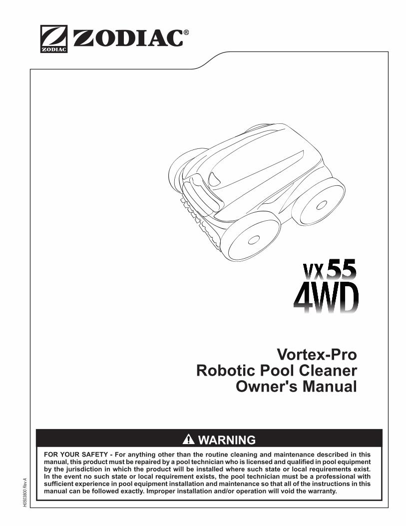
1. Choose pool cleaning settings to program.
• Choose to select either the pool floororthefloorandwallsofthepool. • Choose to select Walls only in addition to Floor Only or Floor and Walls. • Choose to select intensive or high intensity level cleaning. • Choose to select pool shape.
2. Press to view current programmed cleaning cycles. Cycle day and time is displayed for three seconds.
3. When the cleaning cycle you want to change is displayed, press and hold for 3 to 5 seconds. Thedaysoftheweekflashtwice.
NOTE: Ifthedisplayflashesallzeros,thetimehasnotbeenset(newcleaner).Dayandtimemustbesetbeforeyoucanprogramcleaningtimes,seesection5.2 Changing the Clock Day and Time.
4. Press or buttons to cycle through 7 days of the week.
5. Press to select.
Hour setting flashes twice.
6. Press or buttons to cycle through 24 hours.
7. Press to select.
Minutes setting flashes zero.
8. Press or buttons to cycle through four 15- minute increments (00, 15, 30, or 45).
10. Press to select.
The next day to program flashes.
11. Press to program an additional cleaning cycle for a different day OR
Press to exit the programming menu
Days of the week are lit indicating programs stored in the control box memory for that day.
5.5 Cancelling Cleaning Cycles
To Cancel an Individual Program:
1. Press and hold for 3 to 5 seconds.
Thedaysoftheweekflashtwice.
2. Press or buttons to cycle through seven (7) days.
NOTE: Ifthedayoftheweekflasheswithnotimedisplayed,thereisnoprogramsetforthatday.
H0503800_REV A14

3. Press and hold for 3 to 5 seconds to delete programming for the selected day.
Press to exit.
To Cancel All Programs:
1. Press to make sure you have exited the Programming Menu.
2. Press and hold to delete all programming in the control box.
The display will turn off for one (1) second. When all programs are cancelled, the current day and time is displayed on the screen with no days of the week lit.
Section 6. Cleaning and Maintenance
WARNINGToavoidelectricshockandotherhazardswhichcouldresultinpermanentinjuryordeath,disconnect(unplug)thecontrolboxfromthepowersourcebeforeperforminganycleaningandmaintenance.
6.1 Cleaning the Filter CanisterThefiltercanistershouldbecleanedattheendofeachcycle.
1. Make sure the control box cable is disconnected fromtheelectricaloutletorthefloatingcablehas been disconnected from the control box.
2. Remove the cleaner from the water and let the remaining water drain by maintaining the cleaner in the vertical position.
3. Set the unit on its wheels.
4. Toremovethefiltercanisterassemblyfromthecleaner, follow steps 5 through 8 below.
5. Push the cover lock (1) and lift the cover (2) until it is secured in the vertical position. (Figure 24).
2
1
Figure 24. Lift Cleaner Cover
6. Removethefiltercanisterassemblyfromthebody (3), as shown in Figure 25.
15 H0503800_REV A

3
Figure 25. Remove Filter Canister Assembly
7. Push the quick release button on the canister assembly(4)andpullopenthefilterassembly(5), as shown in Figure 26.
45
Figure 26. Open Filter Canister Assembly
8. Separatethefiltercanisterfromthefiltersupport (6), as shown in Figure 27.
6
Figure 27. Remove Filter Canister
9. Emptyalldebrisfromthefiltercanister,thenrinsethecanister,thefiltersupport,andthecleaner under water or using a hose, as shown in Figure 28.
Figure 28. Wash Filter Canister
7
6.2. Cord Tangling
IMPORTANTCleanerfloatingcablemaybecometangledifcorrectprocedureisnotfollowedaftereachcleaningcycle.
Tanglingofthefloatingcablecanoccurmorefrequentlywhen operating the cleaner on the automatic timer 7-Day Programmed Cycle. Do not leave the cleaner unattended for prolonged periods and follow the procedure below to avoid excessive tangling.
H0503800_REV A16

After every cleaning cycle:
1. Unplugthefloatingcableatthecontrolbox.
2. Remove the cleaner from the pool and untangle anykinksandcoilsinthefloatingcablestartingat the cleaner head.
3. Removefiltercanisterandrinsewithcleanwater.Plugthefloatingcablebackintothecontrol box and store cleaner for next use.
6.3 Replacing the BrushesThecleanerisfittedwithPVCbrushes.Thereare''wear'' indicators on the brushes (Figure 29). To maintain cleaner performance at its best you need to replace the brushes as soon as one of the wear indicators is reached (even if the blade wear is not even). It is recommended that you replace the brushes when the rubber is worn down to the top of the wear indicator(oreverytwoyears,whichevercomesfirst).
Figure 29. Wear Indicators1. Lift the cleaner to a vertical position so that the
handle is up (Figure 30).
1
Figure 30. Cleaner in Upright Position2. Separate the edges of the brush and undo the
tabs (Figure 31). Remove the worn brushes.
2
Figure 31. Undo the Tabs of the Brush
17 H0503800_REV A

3. To install a new brush matt, position the new brush matt on the roller with the bristles facing downwards (Figure 32).
3
Figure 32. Install the New Brush4. Thread each tab into the slot provided and
gently feed it through until the heel comes out at the other side of the slot (Figure 33).
4
Figure 33. Pull Tabs Through Each Slot
5. Use scissors to cut the tabs at the guides, as shown in Figure 34.
Figure 34. Cut Tabs
6. Repeat this procedure to replace the second brush matt.
6.4 Replacing the Tyres1. Pull on the inside of the old tyre to remove the
tyre lip from the wheel (Figure 35).
1
Figure 35. Pull the Old Tyre Over the Wheel
2. Remove the old tyre (Figure 36).
2
Figure 36. Remove the Old Tyre
3. To replace the tyre, position the tyre on the wheel making sure to orient the tyre so that the word INSIDE is toward the body of the cleaner (Figure 37).
H0503800_REV A18

Figure 37. Tyre Replacement Orientation
1
I N S I D E
TowardsBody
INS
IDE
INSIDE
4. Push one side of the tyre on to the wheel and fittheribofthetyreinthegrooveofthewheel(Figure 38).
2
Figure 38. Start on One Side of the Tyre
5. Work the tyre onto the wheel and verify the rib of the tyre is positioned properly within the groove of the wheel (Figure 39).
3
Figure 39. Work the Tyre On Around the Wheel
6. Push and position the rib of the inner side of the tyre in the groove of the wheel (Figure 40). If needed, turn the wheel gently to help with installation.
4
Figure 40. Push the Tyre into Place on the Wheel
Section 7. Spare Parts
The complete spare parts list and exploded view is available on the Zodiac website at
www.zodiac.co.za
19 H0503800_REV A
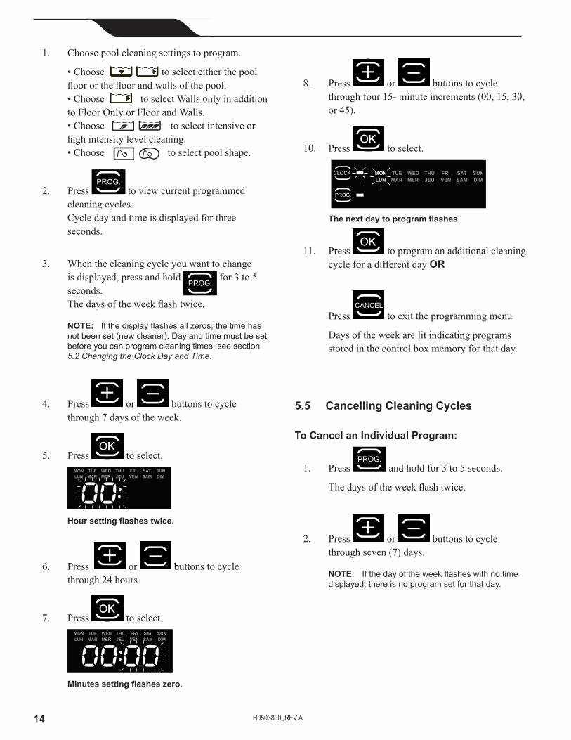
Section 8. Troubleshooting8.1 Viewing Cleaner Status Information for Troubleshooting Information about your cleaner's current status and any relevent error condition is available through a troubleshooting status screen. After cycling through each message, control box returns to current day and time display. To view cleaner status information:
1. Remove cleaner from the pool and turn power off.
2. Press and atthesametimeandholdforatleastfive(5)seconds.
The following cleaner operation messages are displayed consecutively for three (3) seconds:
Total hours cleaner has operated since new.
Last error code (if cleaner has had at least one error).
Time (in operating hours) the error occurred.
H0503800_REV A20

8.2 Control Box Error Codes Thecontrolboxwilldisplayoneoftendifferenterrorcodestoindicatespecificproblemswitheitherthecontrolboxormechanically with the cleaner.
• To remove an error code after troubleshooting, press any key and the control box turns off.
• If an error code is displayed and no key pressed, the screen goes into standby mode after 10 minutes of inactivity. Press any key to turn the screen back on.
• When an error is detected, programming for the control box is temporarily suspended. The button is turned off. Press and hold the button to clear the error code and reactivate current programming.
Error Code Cause • Solution123
(1)Pumpshort-circuit.
(2)Rightsidetractionmotor short-circuit
(3)Leftsidetractionmotor short-circuit
• Checkforanysmalldebrisorfloatingcablestoppingbrushesfromturningfreely.
• Checktheconnectorpinsinthefloatingcableforcorrosionorabentpin.
• Turneachwheelonequarterturninonedirectionrepeatedlyuntilrotationissmoothandnotcatching,thenrepeatturningwheelintheoppositedirectionuntilrotationissmooth.
4 Pumpmotoroverconsumption • Checkforsmalldebrisorhairinthefan.• Cleanthefiltercanister.
56
(5)Rightsidedrivemotorsoverconsumption(6)Leftsidedrivemotorsoverconsumption
• Checkforanysmalldebrisorhairandthatthefloatingcableisnotcaught,stoppingbrushesfromturningfreely.
• Turneachwheelonequarterturninonedirectionrepeatedlyuntilrotationissmoothandnotcatching,thenrepeatturningwheelintheoppositedirectionuntilrotationissmooth.
78
(7)Cleanerfloatsonthesurface.(8)Cleaneristurnedonandrunningoutofwater.
• Turncleanerpoweroff,thensubmergecleaner accordingtocorrectprocedure.
9 NOTACLEANERERROR • Endofcyclestatuscode.Cleanerfunctionisnormal.Noactionrequired.
10 Cleanerandcontrolboxcommunicationerror.
• Turncleanerpoweroffthenbackontorestarttheprogram.
• Checkconnectionofthefloatingcableonthecontrolbox.
• Checktheconnectorpinsinthefloatingcableforcorrosionorabentpin.
If any of the above problems are not resolved through troubleshooting, contact Zodiac Customer Care Line: 0860 POOL (0860 887 665).
21 H0503800_REV A
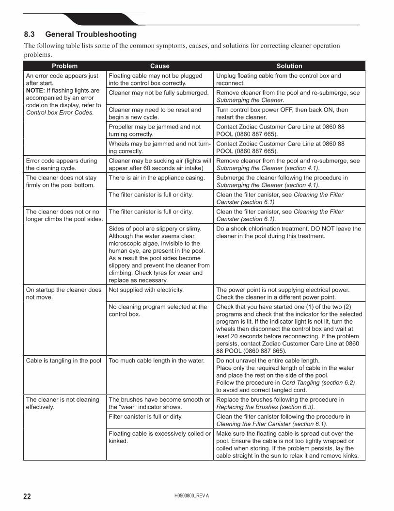
Problem Cause SolutionAnerrorcodeappearsjustafterstart.NOTE:Ifflashinglightsareaccompaniedbyanerrorcodeonthedisplay,refertoControl box Error Codes.
Floatingcablemaynotbepluggedintothecontrolboxcorrectly.
Unplugfloatingcablefromthecontrolboxandreconnect.
Cleanermaynotbefullysubmerged. Removecleanerfromthepoolandre-submerge,seeSubmerging the Cleaner.
Cleanermayneedtoberesetandbeginanewcycle.
TurncontrolboxpowerOFF,thenbackON,thenrestartthecleaner.
Propellermaybejammedandnotturningcorrectly.
ContactZodiacCustomerCareLineat086088POOL(0860887665).
Wheelsmaybejammedandnotturn-ingcorrectly.
ContactZodiacCustomerCareLineat086088POOL(0860887665).
Errorcodeappearsduringthecleaningcycle.
Cleanermaybesuckingair(lightswillappearafter60secondsairintake)
Removecleanerfromthepoolandre-submerge,seeSubmerging the Cleaner (section 4.1).
Thecleanerdoesnotstayfirmlyonthepoolbottom.
Thereisairintheappliancecasing. SubmergethecleanerfollowingtheprocedureinSubmerging the Cleaner (section 4.1).
Thefiltercanisterisfullordirty. Cleanthefiltercanister,seeCleaning the Filter Canister (section 6.1)
Thecleanerdoesnotornolongerclimbsthepoolsides.
Thefiltercanisterisfullordirty. Cleanthefiltercanister,seeCleaning the Filter Canister (section 6.1).
Sidesofpoolareslipperyorslimy.Althoughthewaterseemsclear,microscopicalgae,invisibletothehumaneye,arepresentinthepool.Asaresultthepoolsidesbecomeslipperyandpreventthecleanerfromclimbing.Checktyresforwearandreplaceasnecessary.
Doashockchlorinationtreatment.DONOTleavethecleanerinthepoolduringthistreatment.
Onstartupthecleanerdoesnotmove.
Notsuppliedwithelectricity. Thepowerpointisnotsupplyingelectricalpower.Checkthecleanerinadifferentpowerpoint.
Nocleaningprogramselectedatthecontrolbox.
Checkthatyouhavestartedone(1)ofthetwo(2)programsandcheckthattheindicatorfortheselectedprogramislit.Iftheindicatorlightisnotlit,turnthewheelsthendisconnectthecontrolboxandwaitatleast20secondsbeforereconnecting.Iftheproblempersists,contactZodiacCustomerCareLineat086088POOL(0860887665).
Cableistanglinginthepool Toomuchcablelengthinthewater. Donotunraveltheentirecablelength.Placeonlytherequiredlengthofcableinthewaterandplacetherestonthesideofthepool. FollowtheprocedureinCord Tangling (section 6.2) toavoidandcorrecttangledcord.
Thecleanerisnotcleaningeffectively.
Thebrusheshavebecomesmoothorthe"wear"indicatorshows.
Replacethebrushesfollowingtheprocedurein Replacing the Brushes (section 6.3).
Filtercanisterisfullordirty. CleanthefiltercanisterfollowingtheprocedureinCleaning the Filter Canister (section 6.1).
Floatingcableisexcessivelycoiledorkinked.
Makesurethefloatingcableisspreadoutoverthepool.Ensurethecableisnottootightlywrappedorcoiledwhenstoring.Iftheproblempersists,laythecablestraightinthesuntorelaxitandremovekinks.
8.3 General TroubleshootingThe following table lists some of the common symptoms, causes, and solutions for correcting cleaner operation problems.
H0503800_REV A22

Section 9. Conformity
IEC 60335-2-41
Australian Cert. No. SAA100894EA SAA100540
3145455L100001-01A
87002641965
The manufacturer reserves the right to modify these specificationswithoutnotice.Althoughtheroboticpoolcleaners have been tested in a large variety of swimming pools, Zodiac cannot guarantee that this robotic pool cleaner will be compatible with all pools. Some pool features may affect performance. For further advice, please contact your Zodiac dealer.
23 H0503800_REV A

ZODIAC® is a registered trademark of Zodiac International, S.A.S.U, used under license. All other trademarks used herein are the property of their respective owners.
©2015 Zodiac Pool Systems, Inc. H0503800 Rev A
Zodiac Group South Africa Private Bag x127 Halfway House, 1685 011 237 3900 | www.zodiac.co.za