Embed Size (px)
Citation preview
VMWARE HORIZON 7 ENTERPRISE EDITION REFERENCE ARCHITECTUREVMware Horizon 7, Version 7.3 and Later
TECHNICAL WHITE PAPER – JANUARY 2018
T E C H N I C A L W H I T E PA P E R | 2
VMWARE HORIZON 7 ENTERPRISE EDITION REFERENCE ARCHITECTURE
Table of Contents
Executive Summary . . . . . . . . . . . . . . . . . . . . . . . . . . . . . . . . . . . . . . . . . . . . . . . . . . . . . . . . . . . . . . . . . . . . . . . .7
VMware Reference Architectures . . . . . . . . . . . . . . . . . . . . . . . . . . . . . . . . . . . . . . . . . . . . . . . . . . . . . . . . . . . 9
Audience . . . . . . . . . . . . . . . . . . . . . . . . . . . . . . . . . . . . . . . . . . . . . . . . . . . . . . . . . . . . . . . . . . . . . . . . . . . . . . . 9
Horizon 7 Enterprise Edition Solution Overview . . . . . . . . . . . . . . . . . . . . . . . . . . . . . . . . . . . . . . . . . . . . . .10
Platform Integration . . . . . . . . . . . . . . . . . . . . . . . . . . . . . . . . . . . . . . . . . . . . . . . . . . . . . . . . . . . . . . . . . . . . .12
Reference Architecture Design Methodology . . . . . . . . . . . . . . . . . . . . . . . . . . . . . . . . . . . . . . . . . . . . . . . . 13
Business Drivers and Use Cases Definitions . . . . . . . . . . . . . . . . . . . . . . . . . . . . . . . . . . . . . . . . . . . . . . . . . . 14
Business Drivers and Requirements . . . . . . . . . . . . . . . . . . . . . . . . . . . . . . . . . . . . . . . . . . . . . . . . . . . . . . 14
Use Cases . . . . . . . . . . . . . . . . . . . . . . . . . . . . . . . . . . . . . . . . . . . . . . . . . . . . . . . . . . . . . . . . . . . . . . . . . . . . . . 15
Addressing Business Requirements with Horizon 7 Enterprise Edition . . . . . . . . . . . . . . . . . . . . . . 16
Horizon 7 Services Definition . . . . . . . . . . . . . . . . . . . . . . . . . . . . . . . . . . . . . . . . . . . . . . . . . . . . . . . . . . . . . . . 17
Business Process Application Service . . . . . . . . . . . . . . . . . . . . . . . . . . . . . . . . . . . . . . . . . . . . . . . . . . . . 18
Mobile Secure Workspace Service . . . . . . . . . . . . . . . . . . . . . . . . . . . . . . . . . . . . . . . . . . . . . . . . . . . . . . . 19
Dedicated Power Workspace Service . . . . . . . . . . . . . . . . . . . . . . . . . . . . . . . . . . . . . . . . . . . . . . . . . . . . .21
Developer Workspace Service . . . . . . . . . . . . . . . . . . . . . . . . . . . . . . . . . . . . . . . . . . . . . . . . . . . . . . . . . . . 22
High-Performance Workspace Service . . . . . . . . . . . . . . . . . . . . . . . . . . . . . . . . . . . . . . . . . . . . . . . . . . . 23
Architecture Principles and Concepts . . . . . . . . . . . . . . . . . . . . . . . . . . . . . . . . . . . . . . . . . . . . . . . . . . . . . . 24
Pod and Block . . . . . . . . . . . . . . . . . . . . . . . . . . . . . . . . . . . . . . . . . . . . . . . . . . . . . . . . . . . . . . . . . . . . . . . . . . 24
Horizon 7 Enterprise Edition Logical Architecture . . . . . . . . . . . . . . . . . . . . . . . . . . . . . . . . . . . . . . . . . 26
Horizon 7 Enterprise Edition Component Design . . . . . . . . . . . . . . . . . . . . . . . . . . . . . . . . . . . . . . . . . . . . 28
VMware Identity Manager . . . . . . . . . . . . . . . . . . . . . . . . . . . . . . . . . . . . . . . . . . . . . . . . . . . . . . . . . . . . . . . 28
View in Horizon 7 . . . . . . . . . . . . . . . . . . . . . . . . . . . . . . . . . . . . . . . . . . . . . . . . . . . . . . . . . . . . . . . . . . . . . . . 34
Protocol . . . . . . . . . . . . . . . . . . . . . . . . . . . . . . . . . . . . . . . . . . . . . . . . . . . . . . . . . . . . . . . . . . . . . . . . . . . . . . . 39
Unified Access Gateway . . . . . . . . . . . . . . . . . . . . . . . . . . . . . . . . . . . . . . . . . . . . . . . . . . . . . . . . . . . . . . . . .40
VMware App Volumes . . . . . . . . . . . . . . . . . . . . . . . . . . . . . . . . . . . . . . . . . . . . . . . . . . . . . . . . . . . . . . . . . .46
VMware User Environment Manager . . . . . . . . . . . . . . . . . . . . . . . . . . . . . . . . . . . . . . . . . . . . . . . . . . . . .50
True SSO . . . . . . . . . . . . . . . . . . . . . . . . . . . . . . . . . . . . . . . . . . . . . . . . . . . . . . . . . . . . . . . . . . . . . . . . . . . . . . . 55
VMware vRealize Operations Manager for Horizon . . . . . . . . . . . . . . . . . . . . . . . . . . . . . . . . . . . . . . . . 58
VMware ThinApp . . . . . . . . . . . . . . . . . . . . . . . . . . . . . . . . . . . . . . . . . . . . . . . . . . . . . . . . . . . . . . . . . . . . . . . 61
Load Balancing and External Access . . . . . . . . . . . . . . . . . . . . . . . . . . . . . . . . . . . . . . . . . . . . . . . . . . . . . 62
T E C H N I C A L W H I T E PA P E R | 3
VMWARE HORIZON 7 ENTERPRISE EDITION REFERENCE ARCHITECTURE
vSphere Infrastructure Design . . . . . . . . . . . . . . . . . . . . . . . . . . . . . . . . . . . . . . . . . . . . . . . . . . . . . . . . . . . . . 66
vSphere . . . . . . . . . . . . . . . . . . . . . . . . . . . . . . . . . . . . . . . . . . . . . . . . . . . . . . . . . . . . . . . . . . . . . . . . . . . . . . . . 66
vSAN . . . . . . . . . . . . . . . . . . . . . . . . . . . . . . . . . . . . . . . . . . . . . . . . . . . . . . . . . . . . . . . . . . . . . . . . . . . . . . . . . . 67
Networking . . . . . . . . . . . . . . . . . . . . . . . . . . . . . . . . . . . . . . . . . . . . . . . . . . . . . . . . . . . . . . . . . . . . . . . . . . . . 68
NSX for vSphere . . . . . . . . . . . . . . . . . . . . . . . . . . . . . . . . . . . . . . . . . . . . . . . . . . . . . . . . . . . . . . . . . . . . . . . . 70
Physical Environment Design . . . . . . . . . . . . . . . . . . . . . . . . . . . . . . . . . . . . . . . . . . . . . . . . . . . . . . . . . . . . . . 76
Active Directory . . . . . . . . . . . . . . . . . . . . . . . . . . . . . . . . . . . . . . . . . . . . . . . . . . . . . . . . . . . . . . . . . . . . . . . . 76
Group Policy . . . . . . . . . . . . . . . . . . . . . . . . . . . . . . . . . . . . . . . . . . . . . . . . . . . . . . . . . . . . . . . . . . . . . . . . . . . 76
DNS . . . . . . . . . . . . . . . . . . . . . . . . . . . . . . . . . . . . . . . . . . . . . . . . . . . . . . . . . . . . . . . . . . . . . . . . . . . . . . . . . . . 76
DHCP . . . . . . . . . . . . . . . . . . . . . . . . . . . . . . . . . . . . . . . . . . . . . . . . . . . . . . . . . . . . . . . . . . . . . . . . . . . . . . . . . . 76
Certificate Authority . . . . . . . . . . . . . . . . . . . . . . . . . . . . . . . . . . . . . . . . . . . . . . . . . . . . . . . . . . . . . . . . . . . . 77
Microsoft RDS Licensing . . . . . . . . . . . . . . . . . . . . . . . . . . . . . . . . . . . . . . . . . . . . . . . . . . . . . . . . . . . . . . . . 77
Key Management Service . . . . . . . . . . . . . . . . . . . . . . . . . . . . . . . . . . . . . . . . . . . . . . . . . . . . . . . . . . . . . . . 77
Database . . . . . . . . . . . . . . . . . . . . . . . . . . . . . . . . . . . . . . . . . . . . . . . . . . . . . . . . . . . . . . . . . . . . . . . . . . . . . . 77
Load Balancer . . . . . . . . . . . . . . . . . . . . . . . . . . . . . . . . . . . . . . . . . . . . . . . . . . . . . . . . . . . . . . . . . . . . . . . . . . 77
Firewall and External Access Networking . . . . . . . . . . . . . . . . . . . . . . . . . . . . . . . . . . . . . . . . . . . . . . . . . 78
File Servers . . . . . . . . . . . . . . . . . . . . . . . . . . . . . . . . . . . . . . . . . . . . . . . . . . . . . . . . . . . . . . . . . . . . . . . . . . . . 79
Service Integration Design . . . . . . . . . . . . . . . . . . . . . . . . . . . . . . . . . . . . . . . . . . . . . . . . . . . . . . . . . . . . . . . . 79
Common Components . . . . . . . . . . . . . . . . . . . . . . . . . . . . . . . . . . . . . . . . . . . . . . . . . . . . . . . . . . . . . . . . . . 81
Business Process Application Service . . . . . . . . . . . . . . . . . . . . . . . . . . . . . . . . . . . . . . . . . . . . . . . . . . . .84
Mobile Secure Workspace Service . . . . . . . . . . . . . . . . . . . . . . . . . . . . . . . . . . . . . . . . . . . . . . . . . . . . . . . 87
Dedicated Power Workspace Service . . . . . . . . . . . . . . . . . . . . . . . . . . . . . . . . . . . . . . . . . . . . . . . . . . . .90
Developer Workspace Service . . . . . . . . . . . . . . . . . . . . . . . . . . . . . . . . . . . . . . . . . . . . . . . . . . . . . . . . . . . 91
High-Performance Workspace Service . . . . . . . . . . . . . . . . . . . . . . . . . . . . . . . . . . . . . . . . . . . . . . . . . . . 93
User Experience Design . . . . . . . . . . . . . . . . . . . . . . . . . . . . . . . . . . . . . . . . . . . . . . . . . . . . . . . . . . . . . . . . . . 96
Client Devices (Endpoints) . . . . . . . . . . . . . . . . . . . . . . . . . . . . . . . . . . . . . . . . . . . . . . . . . . . . . . . . . . . . . . 96
Sample User Workflows . . . . . . . . . . . . . . . . . . . . . . . . . . . . . . . . . . . . . . . . . . . . . . . . . . . . . . . . . . . . . . . . . 97
Appendix A: Use Case Definitions . . . . . . . . . . . . . . . . . . . . . . . . . . . . . . . . . . . . . . . . . . . . . . . . . . . . . . . . .102
Static Task Worker . . . . . . . . . . . . . . . . . . . . . . . . . . . . . . . . . . . . . . . . . . . . . . . . . . . . . . . . . . . . . . . . . . . . . 102
Mobile Knowledge Worker . . . . . . . . . . . . . . . . . . . . . . . . . . . . . . . . . . . . . . . . . . . . . . . . . . . . . . . . . . . . . 102
Software Developer/IT (Power User) . . . . . . . . . . . . . . . . . . . . . . . . . . . . . . . . . . . . . . . . . . . . . . . . . . . . 102
Multimedia Designer . . . . . . . . . . . . . . . . . . . . . . . . . . . . . . . . . . . . . . . . . . . . . . . . . . . . . . . . . . . . . . . . . . . 103
Contractor . . . . . . . . . . . . . . . . . . . . . . . . . . . . . . . . . . . . . . . . . . . . . . . . . . . . . . . . . . . . . . . . . . . . . . . . . . . . 103
T E C H N I C A L W H I T E PA P E R | 4
VMWARE HORIZON 7 ENTERPRISE EDITION REFERENCE ARCHITECTURE
Appendix B: Management Virtual Machine Specifications . . . . . . . . . . . . . . . . . . . . . . . . . . . . . . . . . . . 104
vCenter Server . . . . . . . . . . . . . . . . . . . . . . . . . . . . . . . . . . . . . . . . . . . . . . . . . . . . . . . . . . . . . . . . . . . . . . . . 104
SQL Server . . . . . . . . . . . . . . . . . . . . . . . . . . . . . . . . . . . . . . . . . . . . . . . . . . . . . . . . . . . . . . . . . . . . . . . . . . . . 105
Connection Server . . . . . . . . . . . . . . . . . . . . . . . . . . . . . . . . . . . . . . . . . . . . . . . . . . . . . . . . . . . . . . . . . . . . . 106
Enrollment Server . . . . . . . . . . . . . . . . . . . . . . . . . . . . . . . . . . . . . . . . . . . . . . . . . . . . . . . . . . . . . . . . . . . . . 106
Composer . . . . . . . . . . . . . . . . . . . . . . . . . . . . . . . . . . . . . . . . . . . . . . . . . . . . . . . . . . . . . . . . . . . . . . . . . . . . . 107
App Volumes Manager . . . . . . . . . . . . . . . . . . . . . . . . . . . . . . . . . . . . . . . . . . . . . . . . . . . . . . . . . . . . . . . . . 108
vRealize Operations Manager . . . . . . . . . . . . . . . . . . . . . . . . . . . . . . . . . . . . . . . . . . . . . . . . . . . . . . . . . . . 109
NSX Manager . . . . . . . . . . . . . . . . . . . . . . . . . . . . . . . . . . . . . . . . . . . . . . . . . . . . . . . . . . . . . . . . . . . . . . . . . .110
Appendix C: Horizon 7 Installation and Configuration . . . . . . . . . . . . . . . . . . . . . . . . . . . . . . . . . . . . . . . .111
Installation Prerequisites . . . . . . . . . . . . . . . . . . . . . . . . . . . . . . . . . . . . . . . . . . . . . . . . . . . . . . . . . . . . . . . . 111
Horizon 7 Installation Steps . . . . . . . . . . . . . . . . . . . . . . . . . . . . . . . . . . . . . . . . . . . . . . . . . . . . . . . . . . . . . . 112
Preparation . . . . . . . . . . . . . . . . . . . . . . . . . . . . . . . . . . . . . . . . . . . . . . . . . . . . . . . . . . . . . . . . . . . . . . . . . . . . 113
Deployment . . . . . . . . . . . . . . . . . . . . . . . . . . . . . . . . . . . . . . . . . . . . . . . . . . . . . . . . . . . . . . . . . . . . . . . . . . . . 113
Post-Installation Configuration . . . . . . . . . . . . . . . . . . . . . . . . . . . . . . . . . . . . . . . . . . . . . . . . . . . . . . . . . . . 113
Certificates . . . . . . . . . . . . . . . . . . . . . . . . . . . . . . . . . . . . . . . . . . . . . . . . . . . . . . . . . . . . . . . . . . . . . . . . . . . . . 114
Pool Settings . . . . . . . . . . . . . . . . . . . . . . . . . . . . . . . . . . . . . . . . . . . . . . . . . . . . . . . . . . . . . . . . . . . . . . . . . . . 115
RDS Farm Settings . . . . . . . . . . . . . . . . . . . . . . . . . . . . . . . . . . . . . . . . . . . . . . . . . . . . . . . . . . . . . . . . . . . . . 116
Appendix D: Unified Access Gateway Installation and Configuration . . . . . . . . . . . . . . . . . . . . . . . . . . 117
Appliance Requirements . . . . . . . . . . . . . . . . . . . . . . . . . . . . . . . . . . . . . . . . . . . . . . . . . . . . . . . . . . . . . . . . 117
Deployment Options . . . . . . . . . . . . . . . . . . . . . . . . . . . . . . . . . . . . . . . . . . . . . . . . . . . . . . . . . . . . . . . . . . . . 117
Installation Prerequisites . . . . . . . . . . . . . . . . . . . . . . . . . . . . . . . . . . . . . . . . . . . . . . . . . . . . . . . . . . . . . . . . 118
Connection Server Settings . . . . . . . . . . . . . . . . . . . . . . . . . . . . . . . . . . . . . . . . . . . . . . . . . . . . . . . . . . . . . 119
Firewall Rules . . . . . . . . . . . . . . . . . . . . . . . . . . . . . . . . . . . . . . . . . . . . . . . . . . . . . . . . . . . . . . . . . . . . . . . . . 120
Deployment . . . . . . . . . . . . . . . . . . . . . . . . . . . . . . . . . . . . . . . . . . . . . . . . . . . . . . . . . . . . . . . . . . . . . . . . . . . 120
Deployment Steps . . . . . . . . . . . . . . . . . . . . . . . . . . . . . . . . . . . . . . . . . . . . . . . . . . . . . . . . . . . . . . . . . . . . . . 121
T E C H N I C A L W H I T E PA P E R | 5
VMWARE HORIZON 7 ENTERPRISE EDITION REFERENCE ARCHITECTURE
Appendix E: Building a Master VM Template . . . . . . . . . . . . . . . . . . . . . . . . . . . . . . . . . . . . . . . . . . . . . . . . 122
Build a New VM and Tune Hardware . . . . . . . . . . . . . . . . . . . . . . . . . . . . . . . . . . . . . . . . . . . . . . . . . . . . 122
vGPU Specifications . . . . . . . . . . . . . . . . . . . . . . . . . . . . . . . . . . . . . . . . . . . . . . . . . . . . . . . . . . . . . . . . . . . 124
Tune Windows . . . . . . . . . . . . . . . . . . . . . . . . . . . . . . . . . . . . . . . . . . . . . . . . . . . . . . . . . . . . . . . . . . . . . . . . 124
VMware OS Optimization Tool . . . . . . . . . . . . . . . . . . . . . . . . . . . . . . . . . . . . . . . . . . . . . . . . . . . . . . . . . . 126
RDSH Specifications . . . . . . . . . . . . . . . . . . . . . . . . . . . . . . . . . . . . . . . . . . . . . . . . . . . . . . . . . . . . . . . . . . . 126
Applications . . . . . . . . . . . . . . . . . . . . . . . . . . . . . . . . . . . . . . . . . . . . . . . . . . . . . . . . . . . . . . . . . . . . . . . . . . . 127
Antivirus Best Practices (If Not Using Endpoint Antivirus) . . . . . . . . . . . . . . . . . . . . . . . . . . . . . . . . 127
Install VMware Tools and Agents . . . . . . . . . . . . . . . . . . . . . . . . . . . . . . . . . . . . . . . . . . . . . . . . . . . . . . . . 127
Finalize . . . . . . . . . . . . . . . . . . . . . . . . . . . . . . . . . . . . . . . . . . . . . . . . . . . . . . . . . . . . . . . . . . . . . . . . . . . . . . . 128
Appendix F: Group Policies . . . . . . . . . . . . . . . . . . . . . . . . . . . . . . . . . . . . . . . . . . . . . . . . . . . . . . . . . . . . . . .129
OU GPO Best Practices . . . . . . . . . . . . . . . . . . . . . . . . . . . . . . . . . . . . . . . . . . . . . . . . . . . . . . . . . . . . . . . . 129
Common GPO Settings for Desktop and RDSH Server VMs . . . . . . . . . . . . . . . . . . . . . . . . . . . . . . . 130
Desktop . . . . . . . . . . . . . . . . . . . . . . . . . . . . . . . . . . . . . . . . . . . . . . . . . . . . . . . . . . . . . . . . . . . . . . . . . . . . . . 130
RDS Host OU Level . . . . . . . . . . . . . . . . . . . . . . . . . . . . . . . . . . . . . . . . . . . . . . . . . . . . . . . . . . . . . . . . . . . . . 131
User Configuration Settings . . . . . . . . . . . . . . . . . . . . . . . . . . . . . . . . . . . . . . . . . . . . . . . . . . . . . . . . . . . . 132
User Environment Manager – Group Policy Settings . . . . . . . . . . . . . . . . . . . . . . . . . . . . . . . . . . . . . . 133
Appendix G: Smart Policies . . . . . . . . . . . . . . . . . . . . . . . . . . . . . . . . . . . . . . . . . . . . . . . . . . . . . . . . . . . . . . .134
Appendix H: Mandatory Profile . . . . . . . . . . . . . . . . . . . . . . . . . . . . . . . . . . . . . . . . . . . . . . . . . . . . . . . . . . . . 137
Create the Mandatory Profile . . . . . . . . . . . . . . . . . . . . . . . . . . . . . . . . . . . . . . . . . . . . . . . . . . . . . . . . . . . 137
Configure Active Directory Group Policies for Mandatory Profile . . . . . . . . . . . . . . . . . . . . . . . . . . 138
Appendix I: VMware App Volumes Installation and Configuration . . . . . . . . . . . . . . . . . . . . . . . . . . . 140
Prerequisites . . . . . . . . . . . . . . . . . . . . . . . . . . . . . . . . . . . . . . . . . . . . . . . . . . . . . . . . . . . . . . . . . . . . . . . . . . 140
Install . . . . . . . . . . . . . . . . . . . . . . . . . . . . . . . . . . . . . . . . . . . . . . . . . . . . . . . . . . . . . . . . . . . . . . . . . . . . . . . . . 140
Next Steps . . . . . . . . . . . . . . . . . . . . . . . . . . . . . . . . . . . . . . . . . . . . . . . . . . . . . . . . . . . . . . . . . . . . . . . . . . . . 140
Appendix J: Printing . . . . . . . . . . . . . . . . . . . . . . . . . . . . . . . . . . . . . . . . . . . . . . . . . . . . . . . . . . . . . . . . . . . . . . 141
USB Redirection and Printing . . . . . . . . . . . . . . . . . . . . . . . . . . . . . . . . . . . . . . . . . . . . . . . . . . . . . . . . . . . . 141
Location-Based Printing Overview . . . . . . . . . . . . . . . . . . . . . . . . . . . . . . . . . . . . . . . . . . . . . . . . . . . . . . . 141
Printing Environment . . . . . . . . . . . . . . . . . . . . . . . . . . . . . . . . . . . . . . . . . . . . . . . . . . . . . . . . . . . . . . . . . . 142
T E C H N I C A L W H I T E PA P E R | 6
VMWARE HORIZON 7 ENTERPRISE EDITION REFERENCE ARCHITECTURE
Appendix K: NSX Manager Installation and Configuration . . . . . . . . . . . . . . . . . . . . . . . . . . . . . . . . . . . .143
Installation Prerequisites . . . . . . . . . . . . . . . . . . . . . . . . . . . . . . . . . . . . . . . . . . . . . . . . . . . . . . . . . . . . . . . 143
Installation Steps . . . . . . . . . . . . . . . . . . . . . . . . . . . . . . . . . . . . . . . . . . . . . . . . . . . . . . . . . . . . . . . . . . . . . . 143
Post-Installation Configuration . . . . . . . . . . . . . . . . . . . . . . . . . . . . . . . . . . . . . . . . . . . . . . . . . . . . . . . . . . 144
Certificates . . . . . . . . . . . . . . . . . . . . . . . . . . . . . . . . . . . . . . . . . . . . . . . . . . . . . . . . . . . . . . . . . . . . . . . . . . . . 144
Appendix L: NSX Distributed Firewall Rules for Horizon 7 . . . . . . . . . . . . . . . . . . . . . . . . . . . . . . . . . . . .145
Resource Block of VDI and RDSH Machines and Infrastructure . . . . . . . . . . . . . . . . . . . . . . . . . . . . 145
Management Block for Horizon 7 Infrastructure Components . . . . . . . . . . . . . . . . . . . . . . . . . . . . . 149
Appendix M: Product Versions Used in This Reference Architecture . . . . . . . . . . . . . . . . . . . . . . . . . .163
Additional Resources . . . . . . . . . . . . . . . . . . . . . . . . . . . . . . . . . . . . . . . . . . . . . . . . . . . . . . . . . . . . . . . . . . . . 164
About the Authors . . . . . . . . . . . . . . . . . . . . . . . . . . . . . . . . . . . . . . . . . . . . . . . . . . . . . . . . . . . . . . . . . . . . . . 164
T E C H N I C A L W H I T E PA P E R | 7
VMWARE HORIZON 7 ENTERPRISE EDITION REFERENCE ARCHITECTURE
Executive SummaryThis paper describes how to address business requirements and use cases with services constructed by integrating the components of VMware Horizon® 7 Enterprise Edition .
It is intended to help customers—IT architects, consultants, and administrators—involved in the early phases of planning, design, and deployment by offering a standard, repeatable, and highly scalable approach to design and integration that can easily be adapted to specific environments and requirements .
The approach taken in this paper is, as with any technology solution, to start by defining business requirements and drivers . These requirements can, in turn, be mapped to use cases that can be adapted to most scenarios .
With Horizon 7 Enterprise Edition we can deliver solutions for these use cases by creating services composed of several components in a very efficient and reusable manner . The resultant environment and the services delivered can be easily adapted to address changes in the business and use cases .
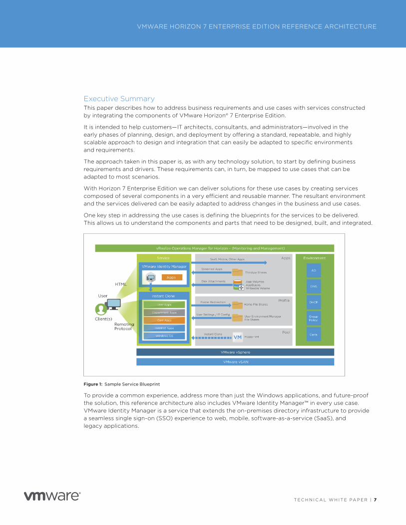
One key step in addressing the use cases is defining the blueprints for the services to be delivered . This allows us to understand the components and parts that need to be designed, built, and integrated .
Figure 1: Sample Service Blueprint
To provide a common experience, address more than just the Windows applications, and future-proof the solution, this reference architecture also includes VMware Identity Manager™ in every use case . VMware Identity Manager is a service that extends the on-premises directory infrastructure to provide a seamless single sign-on (SSO) experience to web, mobile, software-as-a-service (SaaS), and legacy applications .
T E C H N I C A L W H I T E PA P E R | 8
VMWARE HORIZON 7 ENTERPRISE EDITION REFERENCE ARCHITECTURE
T E C H N I C A L W H I T E PA P E R | 8
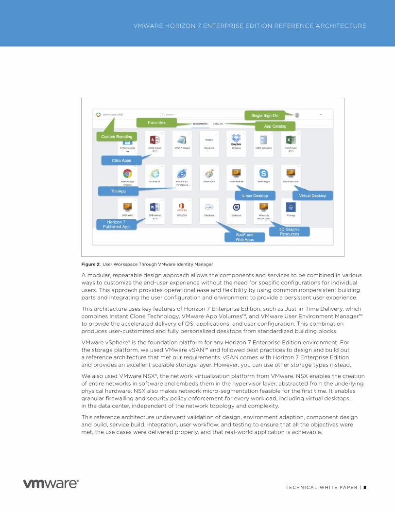
Figure 2: User Workspace Through VMware Identity Manager
A modular, repeatable design approach allows the components and services to be combined in various ways to customize the end-user experience without the need for specific configurations for individual users . This approach provides operational ease and flexibility by using common nonpersistent building parts and integrating the user configuration and environment to provide a persistent user experience .
This architecture uses key features of Horizon 7 Enterprise Edition, such as Just-in-Time Delivery, which combines Instant Clone Technology, VMware App Volumes™, and VMware User Environment Manager™ to provide the accelerated delivery of OS, applications, and user configuration . This combination produces user-customized and fully personalized desktops from standardized building blocks .
VMware vSphere® is the foundation platform for any Horizon 7 Enterprise Edition environment . For the storage platform, we used VMware vSAN™ and followed best practices to design and build out a reference architecture that met our requirements . vSAN comes with Horizon 7 Enterprise Edition and provides an excellent scalable storage layer . However, you can use other storage types instead .
We also used VMware NSX®, the network virtualization platform from VMware . NSX enables the creation of entire networks in software and embeds them in the hypervisor layer, abstracted from the underlying physical hardware . NSX also makes network micro-segmentation feasible for the first time . It enables granular firewalling and security policy enforcement for every workload, including virtual desktops, in the data center, independent of the network topology and complexity .
This reference architecture underwent validation of design, environment adaption, component design and build, service build, integration, user workflow, and testing to ensure that all the objectives were met, the use cases were delivered properly, and that real-world application is achievable .
T E C H N I C A L W H I T E PA P E R | 9
VMWARE HORIZON 7 ENTERPRISE EDITION REFERENCE ARCHITECTURE
T E C H N I C A L W H I T E PA P E R | 9
VMware Reference ArchitecturesVMware reference architectures are designed and validated by VMware and supporting partners to address common use cases, such as enterprise desktop replacement, remote access, and disaster recovery .
This reference architecture is intended to provide detailed configuration information and an example architecture for deploying all products in an integrated manner .
This Horizon 7 Enterprise Edition reference architecture presents high-level design and low-level configuration for the key features and integration points of Horizon 7 Enterprise Edition to form cohesive services to address typical business use cases .
VMware reference architectures offer customers:
• Standardized, validated, repeatable components
• Scalable designs that allow room for future growth
• Validated and tested designs that reduce implementation and operational risks
• Quick implementation, reduced costs, and minimized risk
This reference architecture does not provide performance data or stress testing metrics . However, it does provide a structure and guidance on architecting in repeatable blocks for scale . The principles followed include the use of high availability, load balancing, and ensuring that there are no single points of failure to provide a production-ready design .
AudienceThis reference architecture helps customers, IT architects, consultants, and administrators involved in the early phases of planning, designing, and deploying Horizon 7 Enterprise Edition solutions .
The reader should have:
• A solid understanding of desktop and application virtualization
• Familiarity with virtual desktops in VMware Horizon 7
• A solid understanding of firewall policy and load-balancing configurations
T E C H N I C A L W H I T E PA P E R | 1 0
VMWARE HORIZON 7 ENTERPRISE EDITION REFERENCE ARCHITECTURE
T E C H N I C A L W H I T E PA P E R | 1 0
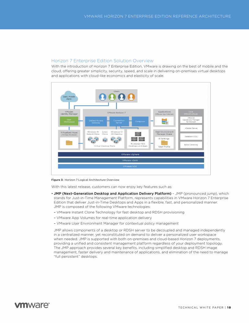
Horizon 7 Enterprise Edition Solution OverviewWith the introduction of Horizon 7 Enterprise Edition, VMware is drawing on the best of mobile and the cloud, offering greater simplicity, security, speed, and scale in delivering on-premises virtual desktops and applications with cloud-like economics and elasticity of scale .
Figure 3: Horizon 7 Logical Architecture Overview
With this latest release, customers can now enjoy key features such as:
• JMP (Next-Generation Desktop and Application Delivery Platform) – JMP (pronounced jump), which stands for Just-in-Time Management Platform, represents capabilities in VMware Horizon 7 Enterprise Edition that deliver Just-in-Time Desktops and Apps in a flexible, fast, and personalized manner . JMP is composed of the following VMware technologies:
– VMware Instant Clone Technology for fast desktop and RDSH provisioning
– VMware App Volumes for real-time application delivery
– VMware User Environment Manager for contextual policy management
JMP allows components of a desktop or RDSH server to be decoupled and managed independently in a centralized manner, yet reconstituted on demand to deliver a personalized user workspace when needed . JMP is supported with both on-premises and cloud-based Horizon 7 deployments, providing a unified and consistent management platform regardless of your deployment topology . The JMP approach provides several key benefits, including simplified desktop and RDSH image management, faster delivery and maintenance of applications, and elimination of the need to manage “full persistent” desktops .
T E C H N I C A L W H I T E PA P E R | 1 1
VMWARE HORIZON 7 ENTERPRISE EDITION REFERENCE ARCHITECTURE
T E C H N I C A L W H I T E PA P E R | 1 1
• Just-in-Time Desktops – Leverages Instant Clone Technology coupled with App Volumes to accelerate the delivery of user-customized and fully personalized desktops . Dramatically reduce infrastructure requirements while enhancing security by delivering a brand new personalized desktop and application services to end users every time they log in .
– Reap the economic benefits of stateless, nonpersistent virtual desktops served up to date upon each login .
– Deliver a pristine, high-performance personalized desktop every time a user logs in .
– Improve security by destroying desktops every time a user logs out .
• VMware App Volumes – Provides real-time application delivery and management .
– Quickly provision applications at scale .
– Dynamically attach applications to users, groups, or devices, even when users are logged in to their desktop .
– Provision, deliver, update, and retire applications in real time .
– Provide a user-writable volume, allowing users to install applications that follow them across desktops .
• VMware User Environment Manager – Offers personalization and dynamic policy configuration across any virtual, physical, and cloud-based environment .
– Provide end users with quick access to a Windows workspace and applications, with a personalized and consistent experience across devices and locations .
– Simplify end-user profile management by providing organizations with a single and scalable solution that leverages the existing infrastructure .
– Speed up the login process by applying configuration and environment settings in an asynchronous process instead of all at login .
– Provide a dynamic environment configuration, such as drive or printer mappings, when a user launches an application .
• Horizon Smart Policies – Deliver a real-time, policy-based system that provides contextual, fine-grained control . IT can intelligently enable or disable client features based on user device, location, and more .
– Conditions can be reevaluated when specific events occur, such as user reconnect, allowing the policies to be contextually applied and reassessed .
– With True SSO, users benefit from single-click, password-free login to their Windows desktops and apps through a single digital workspace .
• Blast Extreme – Provides a high-performance graphics experience accessible on billions of devices, including ultra-low-cost PCs . Purpose-built and optimized for the mobile cloud, this display technology is built on industry-standard H .264 .
– Multi-codec – Blast Extreme supports the JPG/PNG and H .264 codecs .
– Multi-protocol – Supports both TCP and UDP transport protocols .
– Adaptation – Automatically selects the appropriate codec based on endpoint and policy, and the appropriate transport protocol based on network conditions and policy .
T E C H N I C A L W H I T E PA P E R | 1 2
VMWARE HORIZON 7 ENTERPRISE EDITION REFERENCE ARCHITECTURE
T E C H N I C A L W H I T E PA P E R | 1 2
Platform IntegrationVMware Horizon 7 Enterprise Edition extends the power of virtualization with virtual compute, virtual storage, and virtual networking and security to drive down costs, enhance the user experience, and deliver greater business agility .
Horizon 7 Enterprise Edition can leverage native storage optimizations from vSphere, including SE Sparse, VAAI, and storage acceleration, to lower storage costs while delivering a superior user experience .
Horizon 7 Enterprise Edition with vSAN Advanced for Desktop automates storage provisioning and leverages direct-attached storage resources to reduce storage costs for desktop workloads . Horizon 7 supports all-flash capabilities to better support more end users at lower costs across distributed locations .
T E C H N I C A L W H I T E PA P E R | 1 3
VMWARE HORIZON 7 ENTERPRISE EDITION REFERENCE ARCHITECTURE
T E C H N I C A L W H I T E PA P E R | 1 3
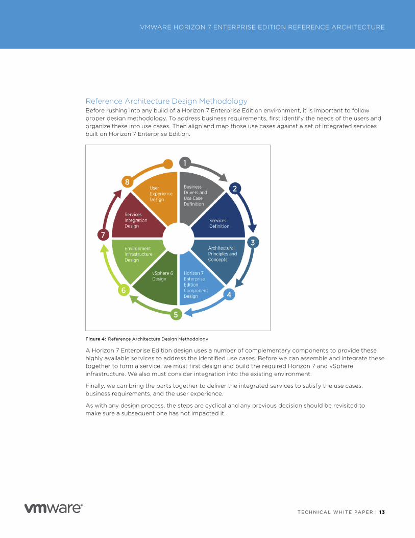
Reference Architecture Design MethodologyBefore rushing into any build of a Horizon 7 Enterprise Edition environment, it is important to follow proper design methodology . To address business requirements, first identify the needs of the users and organize these into use cases . Then align and map those use cases against a set of integrated services built on Horizon 7 Enterprise Edition .
Figure 4: Reference Architecture Design Methodology
A Horizon 7 Enterprise Edition design uses a number of complementary components to provide these highly available services to address the identified use cases . Before we can assemble and integrate these together to form a service, we must first design and build the required Horizon 7 and vSphere infrastructure . We also must consider integration into the existing environment .
Finally, we can bring the parts together to deliver the integrated services to satisfy the use cases, business requirements, and the user experience .
As with any design process, the steps are cyclical and any previous decision should be revisited to make sure a subsequent one has not impacted it .
T E C H N I C A L W H I T E PA P E R | 1 4
VMWARE HORIZON 7 ENTERPRISE EDITION REFERENCE ARCHITECTURE
T E C H N I C A L W H I T E PA P E R | 1 4
Business Drivers and Use Cases DefinitionsAn end-user computing (EUC) solution based on VMware Horizon 7 Enterprise Edition can address a wide-ranging set of business requirements and use cases . In this particular reference architecture, the solution targets the most common requirements and use cases seen in customer deployments to date .
Business Drivers and RequirementsAny technology solution should directly address critical business requirements and drivers . Each and every design choice should center on a specific business requirement . Business requirements could be driven by the end user or by the team deploying EUC services . The top-eight common key business drivers addressed by this solution are:
1 . Provide greater business mobility by providing mobile access to modern and legacy applications on laptops, tablets, and smartphones .
2 . Reduce user support calls by simplifying and securing access to applications .
3 . Allow fast provisioning of and secure access for internal users and third-party suppliers to line-of-business applications .
4 . Centralize and secure corporate data to meet compliance standards .
5 . Reduce application management overhead and reduce application provisioning time .
6 . Simplify root cause analysis and time to resolution of user issues .
7 . Reduce physical device management overhead .
8 . Allow users to access corporate applications and data from their own devices .
T E C H N I C A L W H I T E PA P E R | 1 5
VMWARE HORIZON 7 ENTERPRISE EDITION REFERENCE ARCHITECTURE
T E C H N I C A L W H I T E PA P E R | 1 5
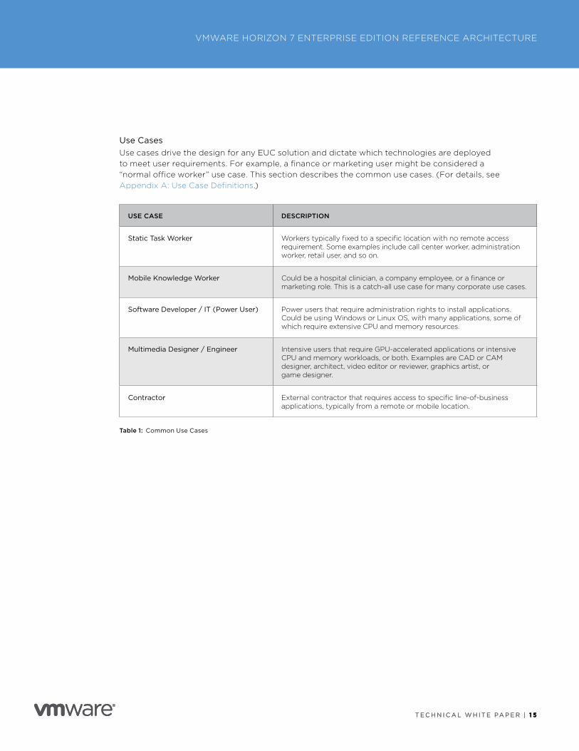
Use CasesUse cases drive the design for any EUC solution and dictate which technologies are deployed to meet user requirements . For example, a finance or marketing user might be considered a “normal office worker” use case . This section describes the common use cases . (For details, see Appendix A: Use Case Definitions .)
USE CASE DESCRIPTION
Static Task Worker Workers typically fixed to a specific location with no remote access requirement . Some examples include call center worker, administration worker, retail user, and so on .
Mobile Knowledge Worker Could be a hospital clinician, a company employee, or a finance or marketing role . This is a catch-all use case for many corporate use cases .
Software Developer / IT (Power User) Power users that require administration rights to install applications . Could be using Windows or Linux OS, with many applications, some of which require extensive CPU and memory resources .
Multimedia Designer / Engineer Intensive users that require GPU-accelerated applications or intensive CPU and memory workloads, or both . Examples are CAD or CAM designer, architect, video editor or reviewer, graphics artist, or game designer .
Contractor External contractor that requires access to specific line-of-business applications, typically from a remote or mobile location .
Table 1: Common Use Cases
T E C H N I C A L W H I T E PA P E R | 1 6
VMWARE HORIZON 7 ENTERPRISE EDITION REFERENCE ARCHITECTURE
T E C H N I C A L W H I T E PA P E R | 1 6
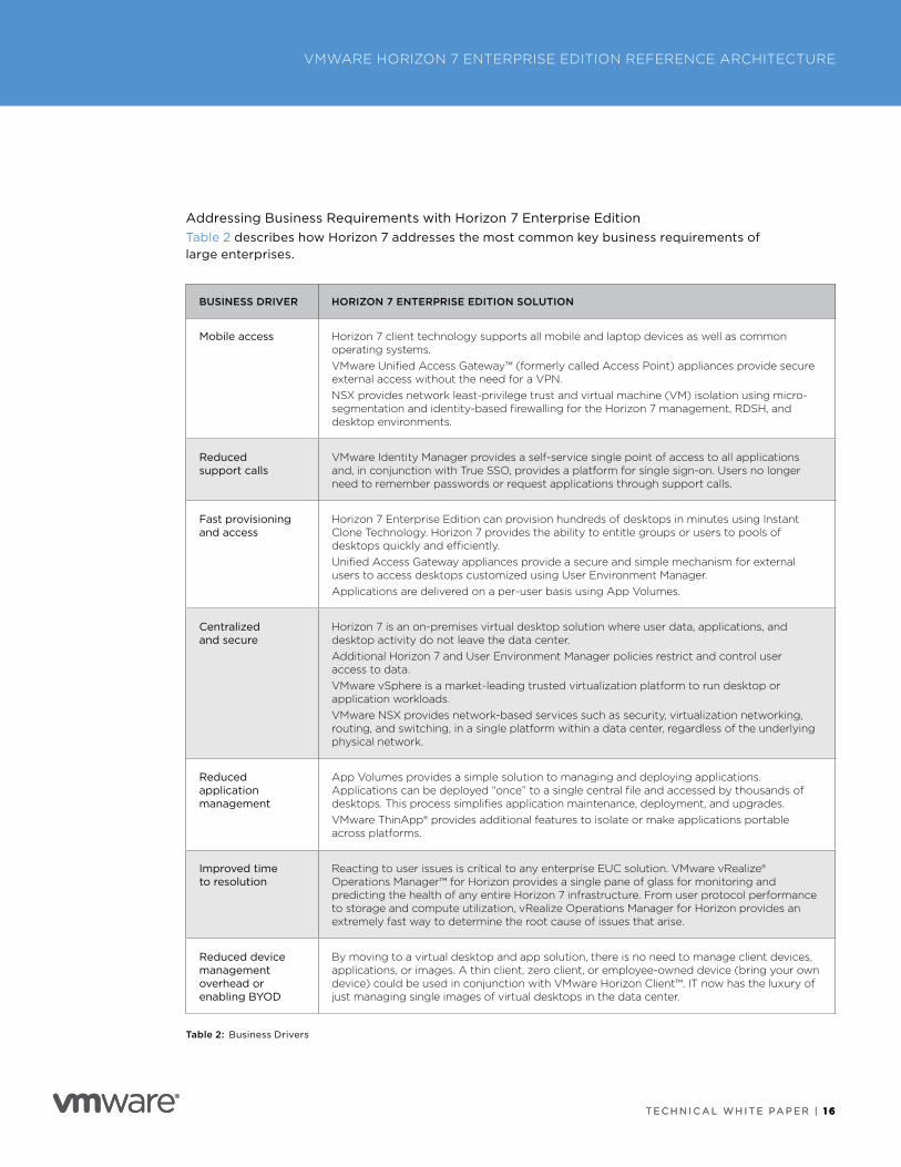
Addressing Business Requirements with Horizon 7 Enterprise EditionTable 2 describes how Horizon 7 addresses the most common key business requirements of large enterprises .
BUSINESS DRIVER HORIZON 7 ENTERPRISE EDITION SOLUTION
Mobile access Horizon 7 client technology supports all mobile and laptop devices as well as common operating systems . VMware Unified Access Gateway™ (formerly called Access Point) appliances provide secure external access without the need for a VPN . NSX provides network least-privilege trust and virtual machine (VM) isolation using micro-segmentation and identity-based firewalling for the Horizon 7 management, RDSH, and desktop environments .
Reduced support calls
VMware Identity Manager provides a self-service single point of access to all applications and, in conjunction with True SSO, provides a platform for single sign-on . Users no longer need to remember passwords or request applications through support calls .
Fast provisioning and access
Horizon 7 Enterprise Edition can provision hundreds of desktops in minutes using Instant Clone Technology . Horizon 7 provides the ability to entitle groups or users to pools of desktops quickly and efficiently . Unified Access Gateway appliances provide a secure and simple mechanism for external users to access desktops customized using User Environment Manager . Applications are delivered on a per-user basis using App Volumes .
Centralized and secure
Horizon 7 is an on-premises virtual desktop solution where user data, applications, and desktop activity do not leave the data center . Additional Horizon 7 and User Environment Manager policies restrict and control user access to data .VMware vSphere is a market-leading trusted virtualization platform to run desktop or application workloads . VMware NSX provides network-based services such as security, virtualization networking, routing, and switching, in a single platform within a data center, regardless of the underlying physical network .
Reduced application management
App Volumes provides a simple solution to managing and deploying applications . Applications can be deployed “once” to a single central file and accessed by thousands of desktops . This process simplifies application maintenance, deployment, and upgrades . VMware ThinApp® provides additional features to isolate or make applications portable across platforms .
Improved time to resolution
Reacting to user issues is critical to any enterprise EUC solution . VMware vRealize® Operations Manager™ for Horizon provides a single pane of glass for monitoring and predicting the health of any entire Horizon 7 infrastructure . From user protocol performance to storage and compute utilization, vRealize Operations Manager for Horizon provides an extremely fast way to determine the root cause of issues that arise .
Reduced device management overhead or enabling BYOD
By moving to a virtual desktop and app solution, there is no need to manage client devices, applications, or images . A thin client, zero client, or employee-owned device (bring your own device) could be used in conjunction with VMware Horizon Client™ . IT now has the luxury of just managing single images of virtual desktops in the data center .
Table 2: Business Drivers
T E C H N I C A L W H I T E PA P E R | 1 7
VMWARE HORIZON 7 ENTERPRISE EDITION REFERENCE ARCHITECTURE
T E C H N I C A L W H I T E PA P E R | 1 7
Horizon 7 Services DefinitionFrom our business requirements, we outlined several typical use cases and their requirements . Taking the business requirements and combining them with one or more use cases enables the definition of a service.
The service defines the unique requirements and identifies the technology or feature combinations that satisfy those unique requirements .
After the service has been defined, you can define the service quality to be associated with that service . These qualities include the performance, availability, security, and management and monitoring requirements to meet service-level agreements (SLAs) .
Note: The remainder of this document details the design to satisfy each of the service definitions .
Do not treat the list of services as exclusive or prescriptive; each environment is different . Adapt the services to your particular use cases . In some cases, that might mean adding additional components, while in others it might be possible to remove some that are not required . You can also combine multiple services to address more complex use cases .
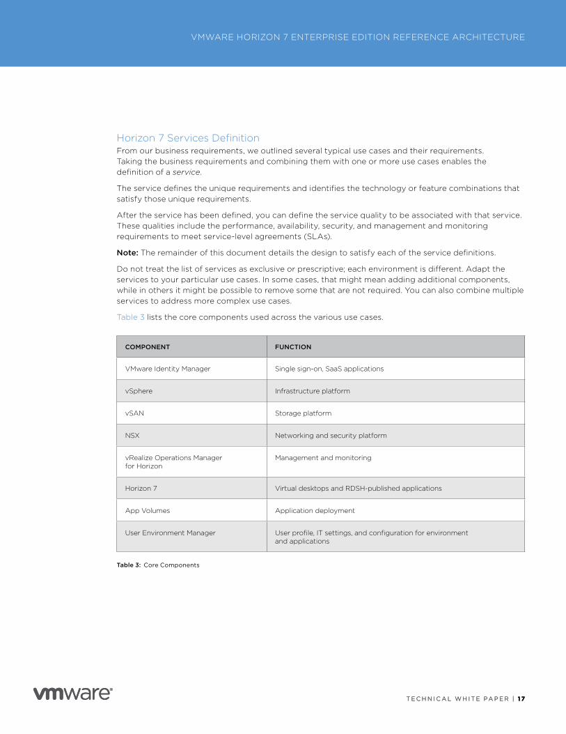
Table 3 lists the core components used across the various use cases .
COMPONENT FUNCTION
VMware Identity Manager Single sign-on, SaaS applications
vSphere Infrastructure platform
vSAN Storage platform
NSX Networking and security platform
vRealize Operations Manager for Horizon
Management and monitoring
Horizon 7 Virtual desktops and RDSH-published applications
App Volumes Application deployment
User Environment Manager User profile, IT settings, and configuration for environment and applications
Table 3: Core Components
T E C H N I C A L W H I T E PA P E R | 1 8
VMWARE HORIZON 7 ENTERPRISE EDITION REFERENCE ARCHITECTURE
T E C H N I C A L W H I T E PA P E R | 1 8
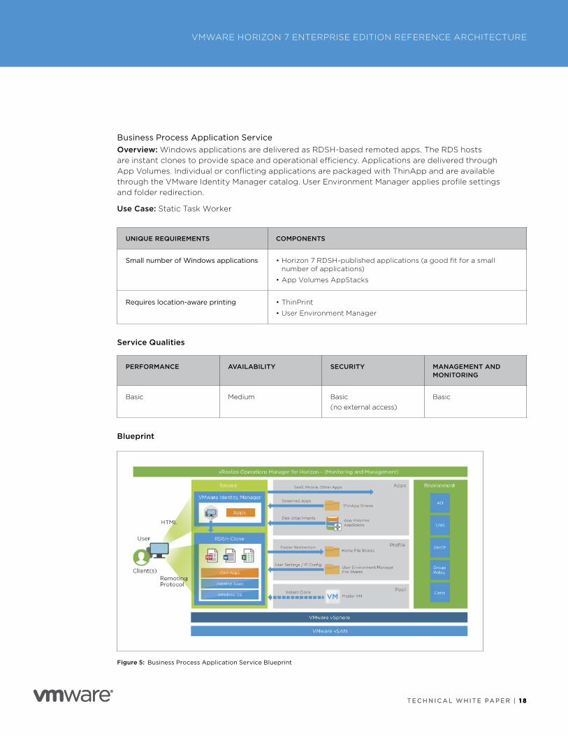
Business Process Application ServiceOverview: Windows applications are delivered as RDSH-based remoted apps . The RDS hosts are instant clones to provide space and operational efficiency . Applications are delivered through App Volumes . Individual or conflicting applications are packaged with ThinApp and are available through the VMware Identity Manager catalog . User Environment Manager applies profile settings and folder redirection .
Use Case: Static Task Worker
UNIQUE REQUIREMENTS COMPONENTS
Small number of Windows applications • Horizon 7 RDSH-published applications (a good fit for a small number of applications)
• App Volumes AppStacks
Requires location-aware printing • ThinPrint
• User Environment Manager
Service Qualities
PERFORMANCE AVAILABILITY SECURITY MANAGEMENT AND MONITORING
Basic Medium Basic(no external access)
Basic
Blueprint
Figure 5: Business Process Application Service Blueprint
T E C H N I C A L W H I T E PA P E R | 1 9
VMWARE HORIZON 7 ENTERPRISE EDITION REFERENCE ARCHITECTURE
T E C H N I C A L W H I T E PA P E R | 1 9
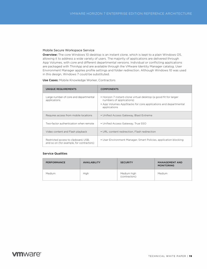
Mobile Secure Workspace ServiceOverview: The core Windows 10 desktop is an instant clone, which is kept to a plain Windows OS, allowing it to address a wide variety of users . The majority of applications are delivered through App Volumes, with core and different departmental versions . Individual or conflicting applications are packaged with ThinApp and are available through the VMware Identity Manager catalog . User Environment Manager applies profile settings and folder redirection . Although Windows 10 was used in this design, Windows 7 could be substituted .
Use Cases: Mobile Knowledge Worker, Contractors
UNIQUE REQUIREMENTS COMPONENTS
Large number of core and departmental applications
• Horizon 7 instant-clone virtual desktop (a good fit for larger numbers of applications)
• App Volumes AppStacks for core applications and departmental applications
Requires access from mobile locations • Unified Access Gateway, Blast Extreme
Two-factor authentication when remote • Unified Access Gateway, True SSO
Video content and Flash playback • URL content redirection, Flash redirection
Restricted access to clipboard, USB, and so on (for example, for contractors)
• User Environment Manager, Smart Policies, application blocking
Service Qualities
PERFORMANCE AVAILABILITY SECURITY MANAGEMENT AND MONITORING
Medium High Medium high (contractors)
Medium
T E C H N I C A L W H I T E PA P E R | 2 0
VMWARE HORIZON 7 ENTERPRISE EDITION REFERENCE ARCHITECTURE
T E C H N I C A L W H I T E PA P E R | 2 0
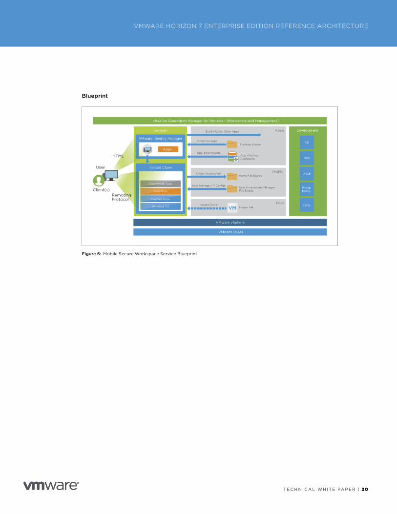
Blueprint
Figure 6: Mobile Secure Workspace Service Blueprint
T E C H N I C A L W H I T E PA P E R | 2 1
VMWARE HORIZON 7 ENTERPRISE EDITION REFERENCE ARCHITECTURE
T E C H N I C A L W H I T E PA P E R | 2 1
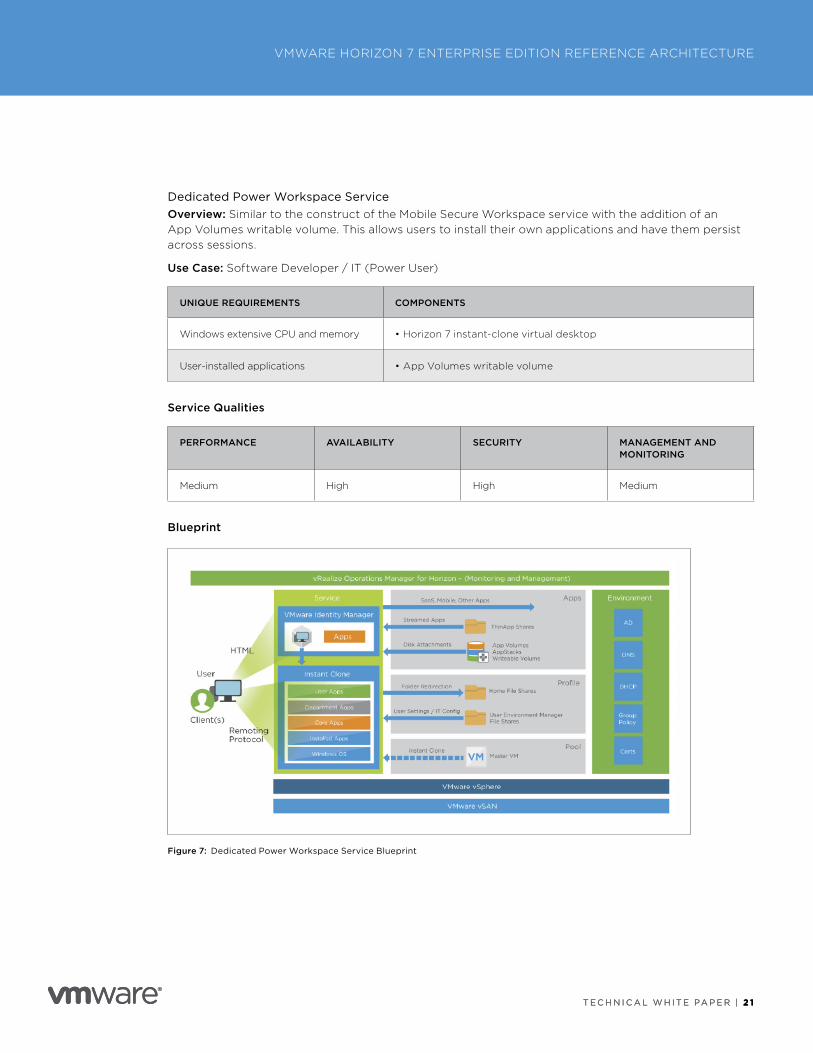
Dedicated Power Workspace ServiceOverview: Similar to the construct of the Mobile Secure Workspace service with the addition of an App Volumes writable volume . This allows users to install their own applications and have them persist across sessions .
Use Case: Software Developer / IT (Power User)
UNIQUE REQUIREMENTS COMPONENTS
Windows extensive CPU and memory • Horizon 7 instant-clone virtual desktop
User-installed applications • App Volumes writable volume
Service Qualities
PERFORMANCE AVAILABILITY SECURITY MANAGEMENT AND MONITORING
Medium High High Medium
Blueprint
Figure 7: Dedicated Power Workspace Service Blueprint
T E C H N I C A L W H I T E PA P E R | 2 2
VMWARE HORIZON 7 ENTERPRISE EDITION REFERENCE ARCHITECTURE
T E C H N I C A L W H I T E PA P E R | 2 2
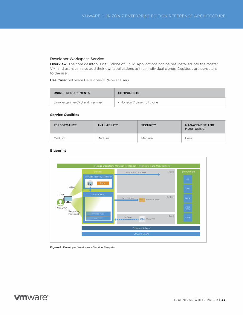
Developer Workspace ServiceOverview: The core desktop is a full clone of Linux . Applications can be pre-installed into the master VM, and users can also add their own applications to their individual clones . Desktops are persistent to the user .
Use Case: Software Developer/IT (Power User)
UNIQUE REQUIREMENTS COMPONENTS
Linux extensive CPU and memory • Horizon 7 Linux full clone
Service Qualities
PERFORMANCE AVAILABILITY SECURITY MANAGEMENT AND MONITORING
Medium Medium Medium Basic
Blueprint
Figure 8: Developer Workspace Service Blueprint
T E C H N I C A L W H I T E PA P E R | 2 3
VMWARE HORIZON 7 ENTERPRISE EDITION REFERENCE ARCHITECTURE
T E C H N I C A L W H I T E PA P E R | 2 3
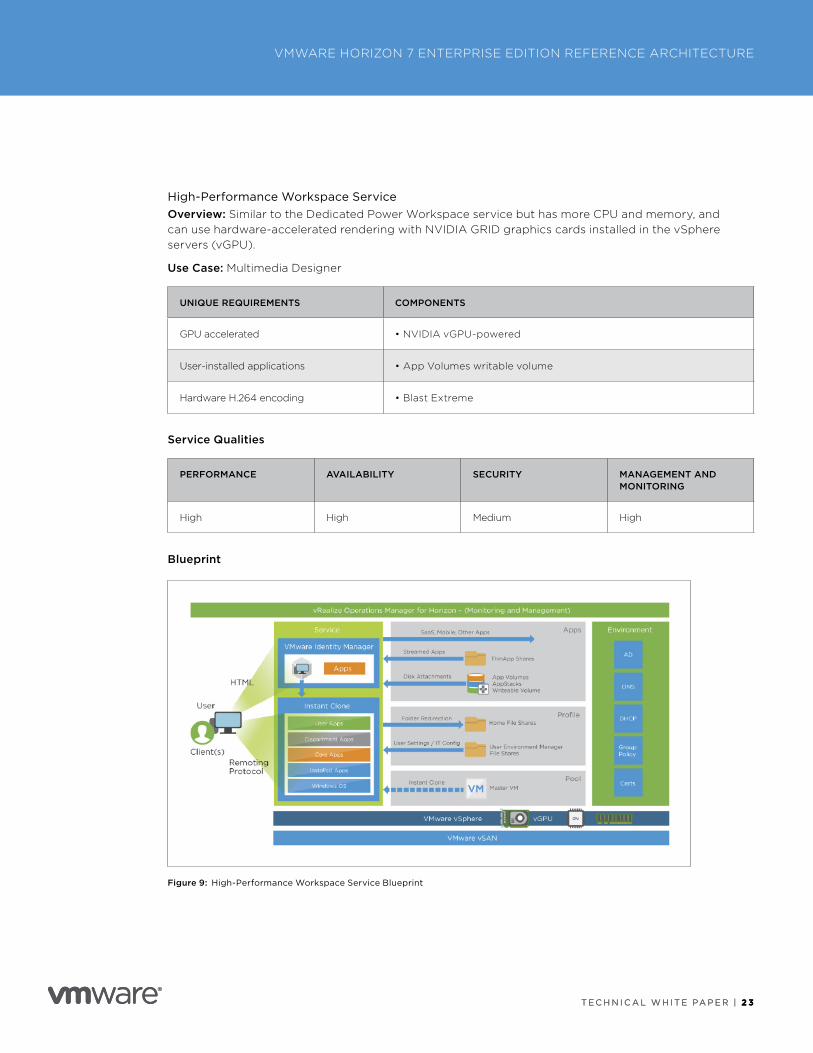
High-Performance Workspace ServiceOverview: Similar to the Dedicated Power Workspace service but has more CPU and memory, and can use hardware-accelerated rendering with NVIDIA GRID graphics cards installed in the vSphere servers (vGPU) .
Use Case: Multimedia Designer
UNIQUE REQUIREMENTS COMPONENTS
GPU accelerated • NVIDIA vGPU-powered
User-installed applications • App Volumes writable volume
Hardware H .264 encoding • Blast Extreme
Service Qualities
PERFORMANCE AVAILABILITY SECURITY MANAGEMENT AND MONITORING
High High Medium High
Blueprint
Figure 9: High-Performance Workspace Service Blueprint
T E C H N I C A L W H I T E PA P E R | 2 4
VMWARE HORIZON 7 ENTERPRISE EDITION REFERENCE ARCHITECTURE
T E C H N I C A L W H I T E PA P E R | 2 4
Architecture Principles and ConceptsA Horizon 7 Enterprise Edition design uses a number of complementary components to provide a variety of highly available services to address the identified use cases . Before we can assemble and integrate these components to form the desired service, we first need to design and build the infrastructure required .
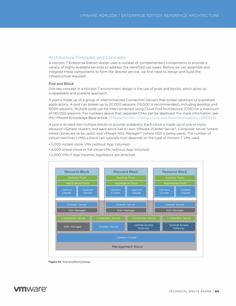
Pod and BlockOne key concept in a Horizon 7 environment design is the use of pods and blocks, which gives us a repeatable and scalable approach .
A pod is made up of a group of interconnected Connection Servers that broker desktops or published applications . A pod can broker up to 20,000 sessions (10,000 is recommended), including desktop and RDSH sessions . Multiple pods can be interconnected using Cloud Pod Architecture (CPA) for a maximum of 140,000 sessions . For numbers above that, separate CPAs can be deployed . For more information, see the VMware Knowledge Base article VMware Horizon 7 Sizing Limits and Recommendations (2150348) .
A pod is divided into multiple blocks to provide scalability . Each block is made up of one or more resource vSphere clusters, and each block has its own VMware vCenter Server®, Composer server (where linked clones are to be used), and VMware NSX Manager™ (where NSX is being used) . The number of virtual machines (VMs) a block can typically host depends on the type of Horizon 7 VMs used:
• 5,000 instant-clone VMs (without App Volumes)
• 4,000 linked-clone or full-clone VMs (without App Volumes)
• 2,000 VMs if App Volumes AppStacks are attached
Figure 10: Pod and Block Design
T E C H N I C A L W H I T E PA P E R | 2 5
VMWARE HORIZON 7 ENTERPRISE EDITION REFERENCE ARCHITECTURE
T E C H N I C A L W H I T E PA P E R | 2 5
To add more resource capacity, you can simply add more resource blocks . We also add an additional Connection Server for each additional block to add the capability for more session connections .
Depending on the types of VMs (instant clones, linked clones, full clones, whether using App Volumes), a resource block could be up to 5,000, 4,000, or 2,000 VMs, respectively . Typically, we have multiple resource blocks and up to seven Connection Servers in a pod capable of hosting 10,000 sessions . For numbers above that, we deploy additional pods .
As you can see, this approach allows us to design a single block capable of thousands of sessions that can then be repeated to create a pod capable of handling 10,000 sessions . Multiple pods grouped using Cloud Pod Architecture can then be used to scale the environment as large as needed .
This guide focuses on the architecture of a complete Horizon 7 Enterprise Edition environment but also concentrates on the design required to build and scale the first block .
For scalability and operational efficiency, it is normally a best practice to have a separate vSphere cluster to host all the management components . This structure keeps the VMs that run services like vCenter Server, NSX Manager, Connection Server, Unified Access Gateway, and databases separate from the desktop and RDSH server VMs . Other Horizon 7 Enterprise Edition components are generally designed to follow this approach to ensure scalability . We detail the design of each of the components later in this document .
Although this separation of management components is generally recommended, management components can be co-hosted on the same vSphere cluster as the end-user resources, if desired . If you place everything on the same vSphere cluster, you must configure the setup to ensure resource prioritization for the management components . Sizing of resources (for example, virtual desktops) must also take into account the overhead of the management servers .
This guide focuses on a relatively simple environment composed of a single resource block and a separate management block .
T E C H N I C A L W H I T E PA P E R | 2 6
VMWARE HORIZON 7 ENTERPRISE EDITION REFERENCE ARCHITECTURE
T E C H N I C A L W H I T E PA P E R | 2 6
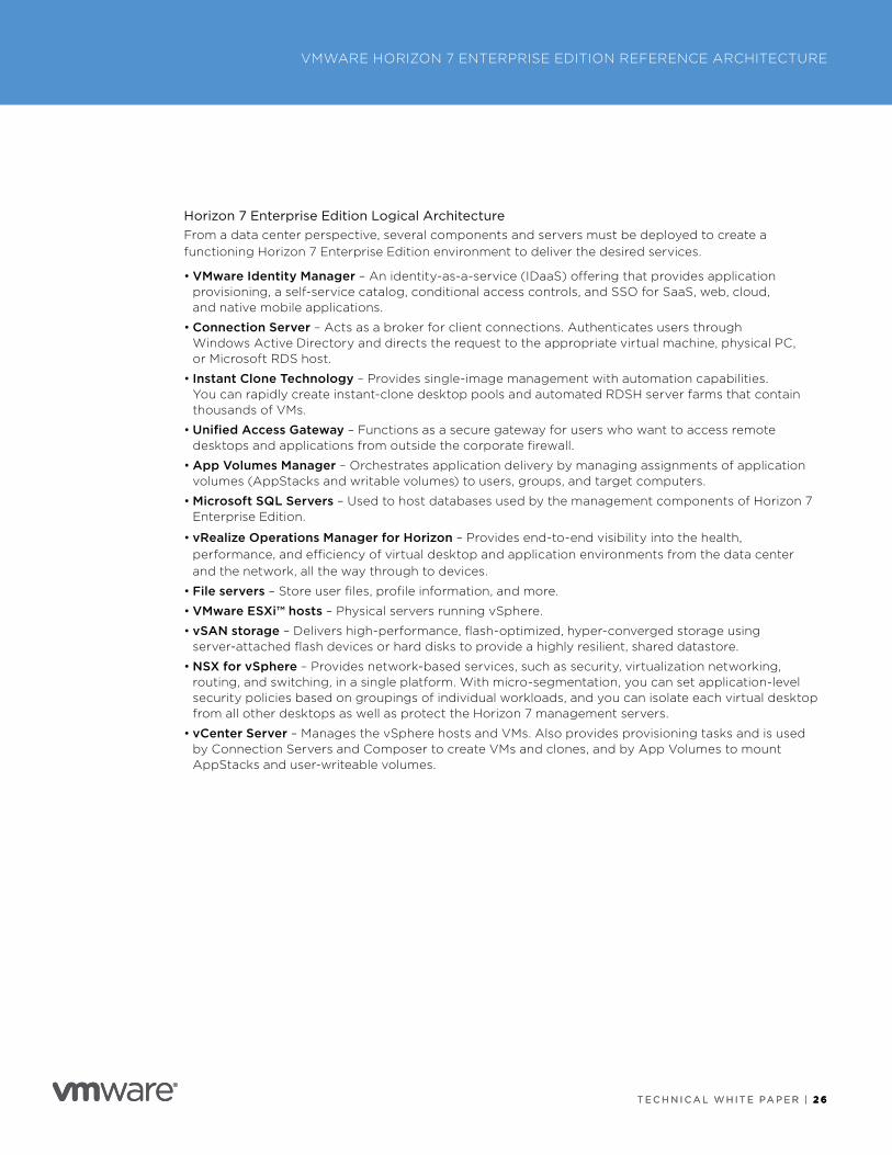
Horizon 7 Enterprise Edition Logical ArchitectureFrom a data center perspective, several components and servers must be deployed to create a functioning Horizon 7 Enterprise Edition environment to deliver the desired services .
• VMware Identity Manager – An identity-as-a-service (IDaaS) offering that provides application provisioning, a self-service catalog, conditional access controls, and SSO for SaaS, web, cloud, and native mobile applications .
• Connection Server – Acts as a broker for client connections . Authenticates users through Windows Active Directory and directs the request to the appropriate virtual machine, physical PC, or Microsoft RDS host .
• Instant Clone Technology – Provides single-image management with automation capabilities . You can rapidly create instant-clone desktop pools and automated RDSH server farms that contain thousands of VMs .
• Unified Access Gateway – Functions as a secure gateway for users who want to access remote desktops and applications from outside the corporate firewall .
• App Volumes Manager – Orchestrates application delivery by managing assignments of application volumes (AppStacks and writable volumes) to users, groups, and target computers .
• Microsoft SQL Servers – Used to host databases used by the management components of Horizon 7 Enterprise Edition .
• vRealize Operations Manager for Horizon – Provides end-to-end visibility into the health, performance, and efficiency of virtual desktop and application environments from the data center and the network, all the way through to devices .
• File servers – Store user files, profile information, and more .
• VMware ESXi™ hosts – Physical servers running vSphere .
• vSAN storage – Delivers high-performance, flash-optimized, hyper-converged storage using server-attached flash devices or hard disks to provide a highly resilient, shared datastore .
• NSX for vSphere – Provides network-based services, such as security, virtualization networking, routing, and switching, in a single platform . With micro-segmentation, you can set application-level security policies based on groupings of individual workloads, and you can isolate each virtual desktop from all other desktops as well as protect the Horizon 7 management servers .
• vCenter Server – Manages the vSphere hosts and VMs . Also provides provisioning tasks and is used by Connection Servers and Composer to create VMs and clones, and by App Volumes to mount AppStacks and user-writeable volumes .
T E C H N I C A L W H I T E PA P E R | 2 7
VMWARE HORIZON 7 ENTERPRISE EDITION REFERENCE ARCHITECTURE
T E C H N I C A L W H I T E PA P E R | 2 7
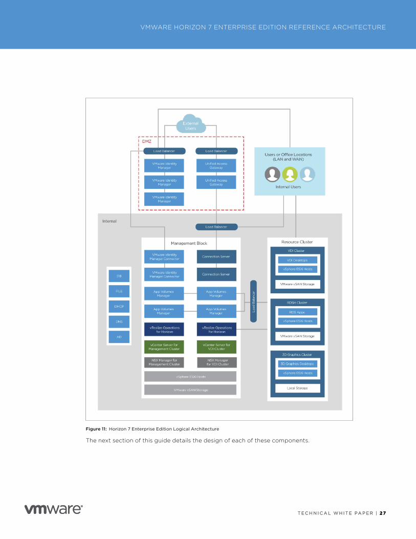
Figure 11: Horizon 7 Enterprise Edition Logical Architecture
The next section of this guide details the design of each of these components .
T E C H N I C A L W H I T E PA P E R | 2 8
VMWARE HORIZON 7 ENTERPRISE EDITION REFERENCE ARCHITECTURE
T E C H N I C A L W H I T E PA P E R | 2 8
Horizon 7 Enterprise Edition Component DesignTo be able to deliver the Horizon 7 Enterprise Edition services outlined in earlier sections, and to address the use cases, we first need to design and build out the infrastructure components required .
This section includes a low-level design of each of the products or areas that need to be considered . This is not an exhaustive design or installation guide, and it is recommended that you also refer to the installation guides .
Installation best practices or recommended configurations for the design outlined in this document can be found in the appendixes .
VMware Identity ManagerVMware Identity Manager provides a number of capabilities for Horizon 7 implementations . VMware Identity Manager is a key component of VMware Workspace™ ONE™ . Among the capabilities of Identity Manager are:
• Simple application access for end users – Provides access to different types of applications, including SaaS-based web applications (such as Salesforce, Dropbox, Concur, and many others), Horizon 7–based applications and desktops, RDSH-published applications and desktops, ThinApp apps, and Citrix-based applications and desktops .
• Enterprise single sign-on – Simplifies business mobility with an included identity provider (IdP), or integration with existing on-premises identity providers so that you can aggregate SaaS and native mobile and Windows 10 apps into a single catalog . Users have a single identity regardless of whether they log in to an internal, external, or virtual-based application .
• Enterprise identity management with adaptive access – Establishes trust between users, devices, and the hybrid cloud for a seamless user experience and powerful conditional access controls that leverage VMware AirWatch® device enrollment and SSO adaptors .
• Self-service app store – Allows end users to search for and select entitled applications in a simple way while providing enterprise security and compliance controls to ensure that the right users have access to the right applications .
T E C H N I C A L W H I T E PA P E R | 2 9
VMWARE HORIZON 7 ENTERPRISE EDITION REFERENCE ARCHITECTURE
T E C H N I C A L W H I T E PA P E R | 2 9
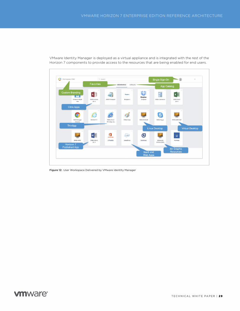
VMware Identity Manager is deployed as a virtual appliance and is integrated with the rest of the Horizon 7 components to provide access to the resources that are being enabled for end users .
Figure 12: User Workspace Delivered by VMware Identity Manager
T E C H N I C A L W H I T E PA P E R | 3 0
VMWARE HORIZON 7 ENTERPRISE EDITION REFERENCE ARCHITECTURE
T E C H N I C A L W H I T E PA P E R | 3 0
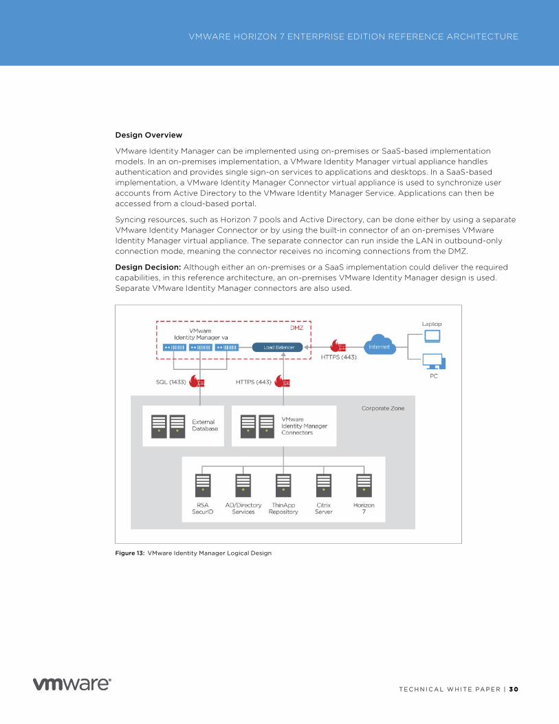
Design Overview
VMware Identity Manager can be implemented using on-premises or SaaS-based implementation models . In an on-premises implementation, a VMware Identity Manager virtual appliance handles authentication and provides single sign-on services to applications and desktops . In a SaaS-based implementation, a VMware Identity Manager Connector virtual appliance is used to synchronize user accounts from Active Directory to the VMware Identity Manager Service . Applications can then be accessed from a cloud-based portal .
Syncing resources, such as Horizon 7 pools and Active Directory, can be done either by using a separate VMware Identity Manager Connector or by using the built-in connector of an on-premises VMware Identity Manager virtual appliance . The separate connector can run inside the LAN in outbound-only connection mode, meaning the connector receives no incoming connections from the DMZ .
Design Decision: Although either an on-premises or a SaaS implementation could deliver the required capabilities, in this reference architecture, an on-premises VMware Identity Manager design is used . Separate VMware Identity Manager connectors are also used .
Figure 13: VMware Identity Manager Logical Design
T E C H N I C A L W H I T E PA P E R | 3 1
VMWARE HORIZON 7 ENTERPRISE EDITION REFERENCE ARCHITECTURE
T E C H N I C A L W H I T E PA P E R | 3 1
Database
VMware Identity Manager can be set up with an internal or external database to store and organize server data . A PostgreSQL database is embedded in the VMware Identity Manager virtual appliance, but this internal database is not recommended for use with production deployments .
To use an external database, have your database administrator prepare an empty external database and schema before you use the VMware Identity Manager Setup wizard to connect to the external database . Licensed users can use an external Microsoft SQL Server 2012, 2014, or 2016 database server to set up a high-availability external database environment . For more information, see Add an External Database to the VMware Identity Manager Appliance in Installing and Configuring VMware Identity Manager .
The database requires 64 GB of disk space for the first 100,000 users, and another 20 GB for each additional 10,000 users .
Design Decision: To make our configuration match that of most enterprises, an external database is implemented .
Scalability and Availability
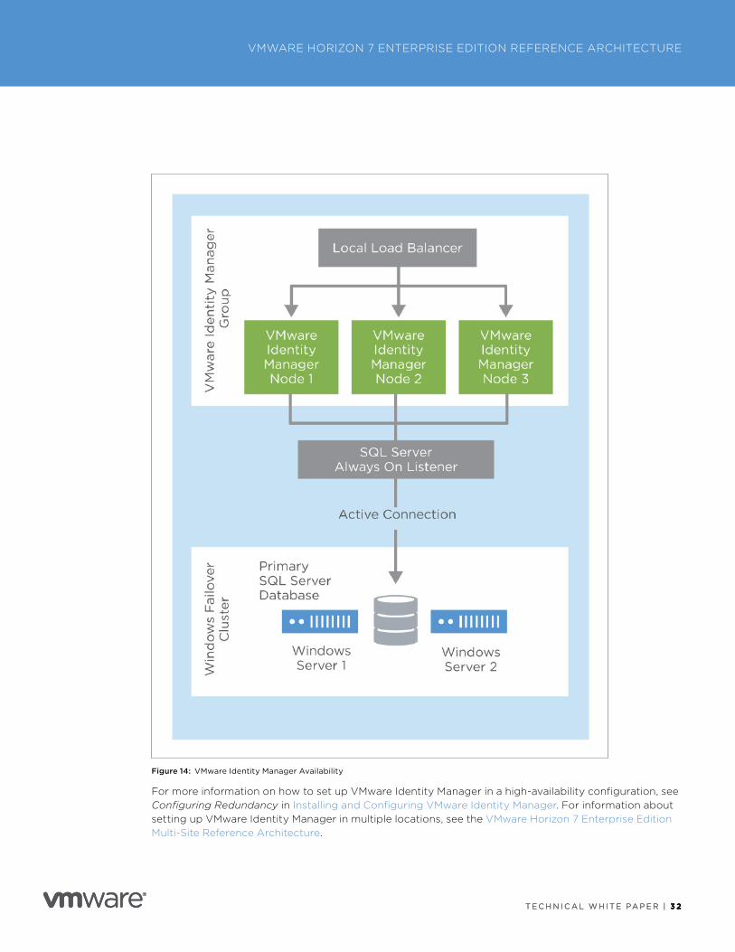
VMware Identity Manager has been tested to 100,000 users per single virtual appliance installation . For a high-availability environment, at least three VMware Identity Manager appliances should be configured to ensure availability in the event of a failure of an appliance or ESXi host . After initial configuration, the virtual appliance is cloned twice and deployed with new IP addresses and host names .
In this reference architecture, we used Microsoft SQL Server 2016 and its cluster offering Always On availability groups, which is supported with VMware Identity Manager . This allows us to deploy multiple instances of VMware Identity Manager, pointing to the same database protected by an availability group, with an availability group listener as the single Java Database Connectivity (JDBC) target for all instances .
Windows Server Failover Clustering (WSFC) is used to improve local database availability and redundancy . In a WSFC cluster, two Windows servers are clustered together to run one instance of SQL Server, which is called a SQL Server failover cluster instance (FCI) . Failover of the SQL Server services between these two Windows servers is automatic .
T E C H N I C A L W H I T E PA P E R | 3 2
VMWARE HORIZON 7 ENTERPRISE EDITION REFERENCE ARCHITECTURE
T E C H N I C A L W H I T E PA P E R | 3 2
Figure 14: VMware Identity Manager Availability
For more information on how to set up VMware Identity Manager in a high-availability configuration, see Configuring Redundancy in Installing and Configuring VMware Identity Manager . For information about setting up VMware Identity Manager in multiple locations, see the VMware Horizon 7 Enterprise Edition Multi-Site Reference Architecture .
T E C H N I C A L W H I T E PA P E R | 3 3
VMWARE HORIZON 7 ENTERPRISE EDITION REFERENCE ARCHITECTURE
T E C H N I C A L W H I T E PA P E R | 3 3
Design Decision: To provide high availability, three VMware Identity Manager 3 .0 appliances are deployed in the DMZ, and two VMware Identity Manager 3 .0 Connectors are deployed inside the corporate LAN, configured to use an outbound-only connection mode . An external SQL Server 2016 database server is installed on a two-node Windows Server Failover Cluster, which uses a SQL Server Always On availability group .
Prerequisites
This section details the prerequisites for the VMware Identity Manager configuration .
vSphere and ESXi
Although several versions are supported, we used vSphere 6 .5 .
NTP
The Network Time Protocol (NTP) must be correctly configured on all hosts and time-synchronized to an NTP server . You must turn on time sync at the ESXi host level, using an NTP server to prevent a time drift between virtual appliances . If you deploy multiple virtual appliances on different hosts, consider disabling the Sync to Host option for time synchronization . Instead, configure the NTP server in each virtual appliance directly to make sure that there is no time drift between virtual appliances .
Network Configuration
• Static IP address and DNS Forward (A) and Reverse (PTR) records .
• Inbound firewall port 443 is open so that users outside the network can connect to the VMware Identity Manager instance or the load balancer .
Active Directory
VMware Identity Manager 3 .0 supports Active Directory configurations on Windows 2008 R2, 2012, 2012 R2, and 2016, including:
• Single AD domain
• Multidomain, single forest
• Multiforest with trust relationships
• Multiforest with untrusted relationships (requires external connector configuration)
• Active Directory Global Catalog optional for Directory Sync
We used Windows 2016 .
Infrastructure Overview
Each VMware Identity Manager 3 .0 appliance has the following minimum requirements:
• 6 GB RAM
• 2 vCPU
• 100 GB disk space
Each VMware Identity Manager 3 .0 Connector appliance has the following minimum requirements:
• 6 GB RAM
• 4 vCPU
• 60 GB disk space
• 1 x vCenter Server is deployed per Horizon 7 block of approximately 2,000 VMs
T E C H N I C A L W H I T E PA P E R | 3 4
VMWARE HORIZON 7 ENTERPRISE EDITION REFERENCE ARCHITECTURE
T E C H N I C A L W H I T E PA P E R | 3 4
Install and Initial Configuration
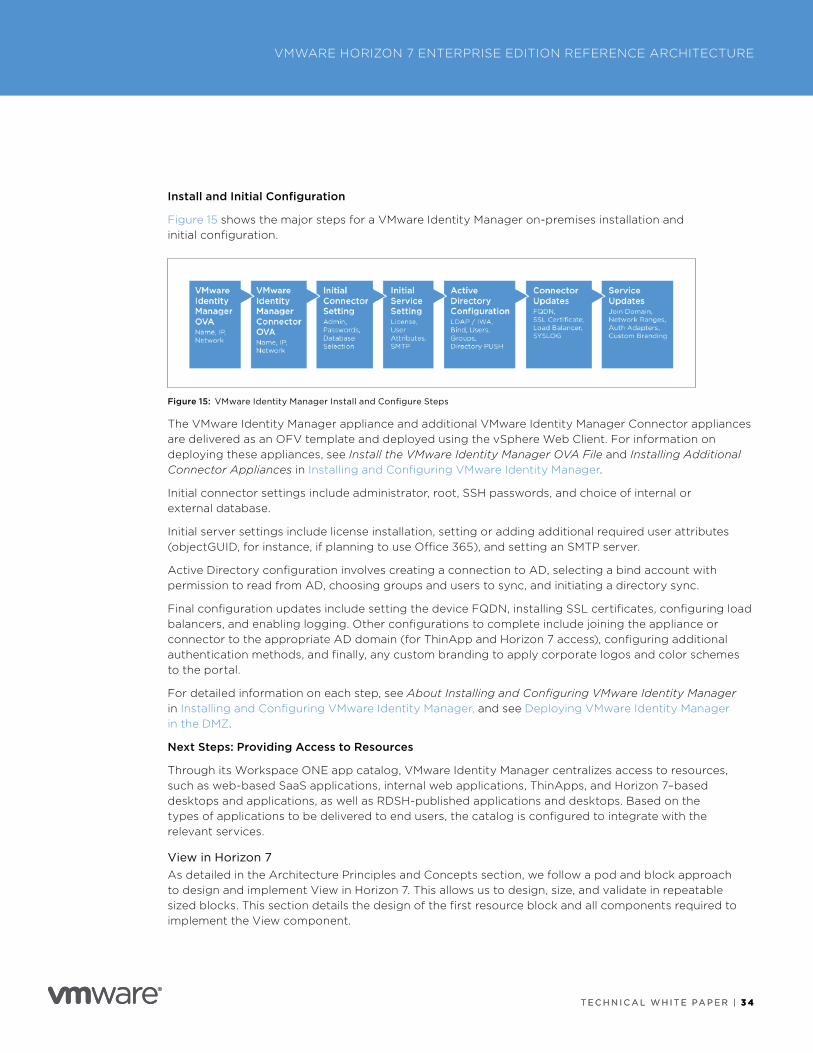
Figure 15 shows the major steps for a VMware Identity Manager on-premises installation and initial configuration .
Figure 15: VMware Identity Manager Install and Configure Steps
The VMware Identity Manager appliance and additional VMware Identity Manager Connector appliances are delivered as an OFV template and deployed using the vSphere Web Client . For information on deploying these appliances, see Install the VMware Identity Manager OVA File and Installing Additional Connector Appliances in Installing and Configuring VMware Identity Manager .
Initial connector settings include administrator, root, SSH passwords, and choice of internal or external database .
Initial server settings include license installation, setting or adding additional required user attributes (objectGUID, for instance, if planning to use Office 365), and setting an SMTP server .
Active Directory configuration involves creating a connection to AD, selecting a bind account with permission to read from AD, choosing groups and users to sync, and initiating a directory sync .
Final configuration updates include setting the device FQDN, installing SSL certificates, configuring load balancers, and enabling logging . Other configurations to complete include joining the appliance or connector to the appropriate AD domain (for ThinApp and Horizon 7 access), configuring additional authentication methods, and finally, any custom branding to apply corporate logos and color schemes to the portal .
For detailed information on each step, see About Installing and Configuring VMware Identity Manager in Installing and Configuring VMware Identity Manager, and see Deploying VMware Identity Manager in the DMZ .
Next Steps: Providing Access to Resources
Through its Workspace ONE app catalog, VMware Identity Manager centralizes access to resources, such as web-based SaaS applications, internal web applications, ThinApps, and Horizon 7–based desktops and applications, as well as RDSH-published applications and desktops . Based on the types of applications to be delivered to end users, the catalog is configured to integrate with the relevant services .
View in Horizon 7As detailed in the Architecture Principles and Concepts section, we follow a pod and block approach to design and implement View in Horizon 7 . This allows us to design, size, and validate in repeatable sized blocks . This section details the design of the first resource block and all components required to implement the View component .
T E C H N I C A L W H I T E PA P E R | 3 5
VMWARE HORIZON 7 ENTERPRISE EDITION REFERENCE ARCHITECTURE
T E C H N I C A L W H I T E PA P E R | 3 5
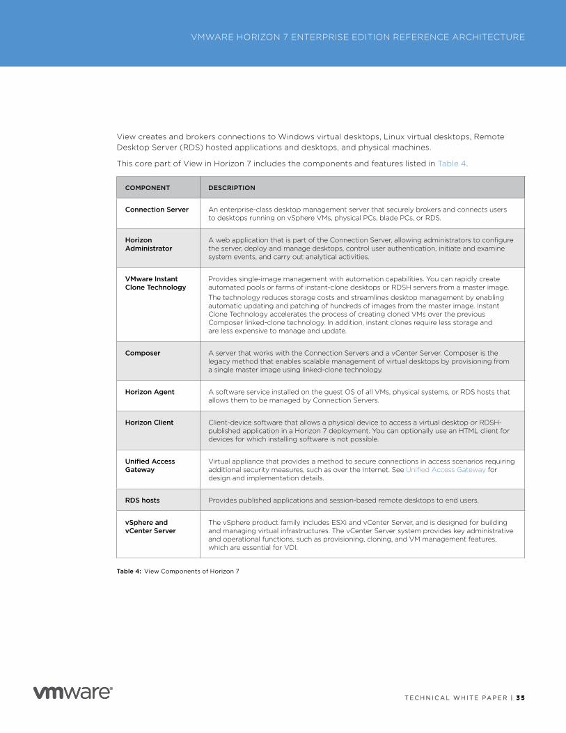
View creates and brokers connections to Windows virtual desktops, Linux virtual desktops, Remote Desktop Server (RDS) hosted applications and desktops, and physical machines .
This core part of View in Horizon 7 includes the components and features listed in Table 4 .
COMPONENT DESCRIPTION
Connection Server An enterprise-class desktop management server that securely brokers and connects users to desktops running on vSphere VMs, physical PCs, blade PCs, or RDS .
Horizon Administrator
A web application that is part of the Connection Server, allowing administrators to configure the server, deploy and manage desktops, control user authentication, initiate and examine system events, and carry out analytical activities .
VMware Instant Clone Technology
Provides single-image management with automation capabilities . You can rapidly create automated pools or farms of instant-clone desktops or RDSH servers from a master image .The technology reduces storage costs and streamlines desktop management by enabling automatic updating and patching of hundreds of images from the master image . Instant Clone Technology accelerates the process of creating cloned VMs over the previous Composer linked-clone technology . In addition, instant clones require less storage and are less expensive to manage and update .
Composer A server that works with the Connection Servers and a vCenter Server . Composer is the legacy method that enables scalable management of virtual desktops by provisioning from a single master image using linked-clone technology .
Horizon Agent A software service installed on the guest OS of all VMs, physical systems, or RDS hosts that allows them to be managed by Connection Servers .
Horizon Client Client-device software that allows a physical device to access a virtual desktop or RDSH-published application in a Horizon 7 deployment . You can optionally use an HTML client for devices for which installing software is not possible .
Unified Access Gateway
Virtual appliance that provides a method to secure connections in access scenarios requiring additional security measures, such as over the Internet . See Unified Access Gateway for design and implementation details .
RDS hosts Provides published applications and session-based remote desktops to end users .
vSphere and vCenter Server
The vSphere product family includes ESXi and vCenter Server, and is designed for building and managing virtual infrastructures . The vCenter Server system provides key administrative and operational functions, such as provisioning, cloning, and VM management features, which are essential for VDI .
Table 4: View Components of Horizon 7
T E C H N I C A L W H I T E PA P E R | 3 6
VMWARE HORIZON 7 ENTERPRISE EDITION REFERENCE ARCHITECTURE
T E C H N I C A L W H I T E PA P E R | 3 6
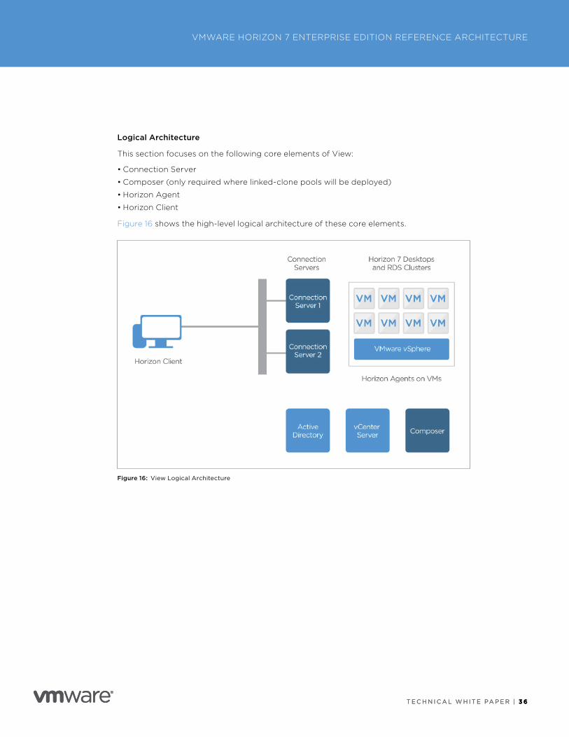
Logical Architecture
This section focuses on the following core elements of View:
• Connection Server
• Composer (only required where linked-clone pools will be deployed)
• Horizon Agent
• Horizon Client
Figure 16 shows the high-level logical architecture of these core elements .
Figure 16: View Logical Architecture
T E C H N I C A L W H I T E PA P E R | 3 7
VMWARE HORIZON 7 ENTERPRISE EDITION REFERENCE ARCHITECTURE
T E C H N I C A L W H I T E PA P E R | 3 7
Design Overview
A successful deployment of Horizon 7 depends on good planning and a robust understanding of the platform . The following sections discuss the design options and details the design decisions that were made to satisfy the design requirements .
Scalability and Availability
One key design principle is to remove single points of failure in the deployment .
vCenter Server
vCenter Server is the delimiter of a resource block . As outlined in Pod and Block, the number of recommended VMs per vCenter Server (and therefore per resource block) depends on the types of VMs in use:
• 5,000 instant-clone VMs (without App Volumes)
• 4,000 linked-clone or full-clone VMs (without App Volumes)
• 2,000 VMs if App Volumes AppStacks are attached
A single vCenter Server can handle 25,000 VMs, but that would introduce a single point of failure that could affect too large a number of objects . It would also have performance implications because a single vCenter Server could become a bottleneck in provisioning tasks .
Design Decision: 1 x vCenter Server is deployed per Horizon 7 block of approximately 2,000 VMs . 2,000 was chosen because this resource block hosts a mix of VM types, including the use of App Volumes AppStacks .
Connection Server
A single Connection Server supports a maximum of 4,000 sessions (Blast Extreme or PCoIP) . 2,000 is recommended as a best practice .
For more information, see the VMware Knowledge Base article VMware Horizon 7 Sizing Limits and Recommendations (2150348) .
To satisfy the requirements that the proposed solution be robust and be able to handle failure, we deploy (n+1) .
Design Decision: 2 x Connection Servers (n+1) are deployed to satisfy the requirement of one resource block capable of hosting up to 2,000 sessions while also providing high availability . Additional Connection Servers can be added if a larger block size is chosen .
For more information, see Appendix C: Horizon 7 Installation and Configuration .
Composer Server
The Composer server is required only when using linked clones . Instant clones do not require a Composer server .
Each Composer server is paired with a vCenter Server, so in a block architecture where we have one vCenter Server per 4,000 linked-clone VMs, we would also have a Composer server .
T E C H N I C A L W H I T E PA P E R | 3 8
VMWARE HORIZON 7 ENTERPRISE EDITION REFERENCE ARCHITECTURE
T E C H N I C A L W H I T E PA P E R | 3 8
High availability is provided by VMware vSphere High Availability (HA), which restarts the Composer VM in the case of a vSphere host outage . VM monitoring with VMware vSphere HA can also attempt to restart the VM in case of an operating system crash . If the VMware View Composer service becomes unavailable, all existing desktops can continue to work just fine . While HA is restarting the Composer VM, the only impact is on any provisioning tasks within that block (image refreshes or recomposes, creating new linked-clone pools) .
Design Decision: Although we did not use Composer in this reference architecture, if you choose to use Composer, deploy one Composer server per block of approximately 4,000 linked-clone VMs .
Load Balancing of Connection Servers
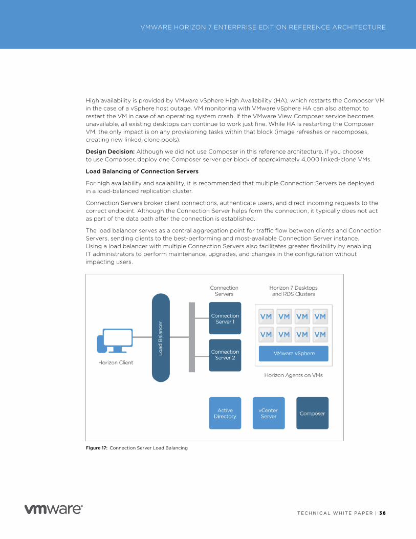
For high availability and scalability, it is recommended that multiple Connection Servers be deployed in a load-balanced replication cluster .
Connection Servers broker client connections, authenticate users, and direct incoming requests to the correct endpoint . Although the Connection Server helps form the connection, it typically does not act as part of the data path after the connection is established .
The load balancer serves as a central aggregation point for traffic flow between clients and Connection Servers, sending clients to the best-performing and most-available Connection Server instance . Using a load balancer with multiple Connection Servers also facilitates greater flexibility by enabling IT administrators to perform maintenance, upgrades, and changes in the configuration without impacting users .
Figure 17: Connection Server Load Balancing
T E C H N I C A L W H I T E PA P E R | 3 9
VMWARE HORIZON 7 ENTERPRISE EDITION REFERENCE ARCHITECTURE
T E C H N I C A L W H I T E PA P E R | 3 9
Connection Servers require the load balancer to have a session persistence setting . This is sometimes referred to as persistent connections or sticky connections, and ensures data stays directed to the relevant Connection Server . For more information, see the VMware Knowledge Base article Load Balancing for VMware Horizon View (2146312) .
Design Decision: A load balancer is placed in front of the Connection Servers for both internal connections and external connections through the Unified Access Gateway appliances . The source IP is configured for the persistence or affinity type .
Authentication
One of the methods of accessing Horizon 7 desktops and applications is through VMware Identity Manager . This method requires integration between Connection Servers and VMware Identity Manager using the SAML 2 .0 standard to establish mutual trust, which is essential for single sign-on (SSO) functionality . When SSO is enabled, users who log in to VMware Identity Manager with Active Directory credentials can launch remote desktops and applications without having to go through a second login procedure . If you set up the True SSO feature, users can log in using authentication mechanisms other than AD credentials . See Using SAML Authentication and see Setting Up True SSO in the View Administration guide for details .
Design Decision: SAML authentication is allowed on the Connection Servers . The Connection Servers are configured to allow VMware Identity Manager to be a dynamic SAML authenticator .
Virtual Machine Build
Connection Servers and Composer servers run as Windows services . Specifications are detailed in Appendix B: Management Virtual Machine Specifications . Each server is deployed with a single network card, and static IP address information is required for each server .
Design Decision: Windows Server 2016 is used for the OS build as the latest supported version . IP address information is allocated for each server .
Physical Hosting
The Connection Server and Composer VMs are part of the management block and are placed on the Management vSphere hosts . vSphere HA and DRS can be used to ensure maximum availability .
ProtocolHorizon 7 is a multi-protocol solution . Three remoting protocols are available when creating desktop pools or RDSH-published applications—RDP, PCoIP, and the new Blast Extreme protocol .
Design Decision: For this design, we leverage Blast Extreme . This display protocol supports multiple codecs (JPG/PNG and H .264), both TCP and UDP from a transport protocol perspective, and the ability to do hardware encoding with NVIDIA GRID vGPU . This protocol has full feature and performance parity with PCoIP and is optimized for mobile devices, which can decode video using the H .264 protocol in hardware .
Configuration
Blast Extreme is configured through Horizon 7 when creating a pool . The Blast Extreme display protocol is integrated directly into the Connection Server so that no separate installation is required . The protocol can also be selected directly on the Horizon Client side when a user selects a desktop pool . Blast Extreme can also use TCP port sharing with Unified Access Gateway so firewall configuration and port requirements can be simplified .

T E C H N I C A L W H I T E PA P E R | 4 0
VMWARE HORIZON 7 ENTERPRISE EDITION REFERENCE ARCHITECTURE
T E C H N I C A L W H I T E PA P E R | 4 0
Prerequisites
In order to use the Blast Extreme display protocol, the following must be in place:
• Horizon 7 infrastructure .
• Horizon Client 4 .x must be used to connect .
Key Design Considerations
• Use H .264 when possible (most modern devices have the ability to hardware-decode H .264) .
• TCP 443 port sharing with Unified Access Gateway simplifies port requirements .
• Even if a pool is forced to Blast Extreme, devices such as PCoIP zero clients will connect using PCoIP .
• Horizon 4 .x Client must be used to connect .
• See the Blast Extreme Display Protocol in VMware Horizon 7 white paper for more information, including optimization tips .
Unified Access GatewayUnified Access Gateway is an integral component in any Horizon 7 deployment . It enables remote access from outside the corporate network to internally hosted virtual desktops and applications . Unified Access Gateway is typically deployed within the corporate DMZ and acts as a proxy host for connections to your company’s resources . Unified Access Gateway directs authenticated requests to the appropriate resource and discards any unauthenticated requests . Unified Access Gateway can also perform authentication, if desired .
To meet the design requirements, Unified Access Gateway appliances are deployed in front of Connection Servers .
Design Overview
A successful deployment of Unified Access Gateway is dependent on good planning and a robust understanding of the platform . The following sections discuss the design options and details the design decisions that are made to satisfy the design requirements .
Scalability
Unified Access Gateway 3 .1 .1 supports a maximum of 2,000 Blast Extreme sessions and 2,000 PCoIP sessions .
To satisfy the requirements that the proposed solution be robust and able to handle failures, we deploy n+1 appliances .
Design Decision: 2 x Unified Access Gateway 3 .1 .1 appliances (n+1) are deployed to satisfy the requirement of 2,000 sessions and high availability .
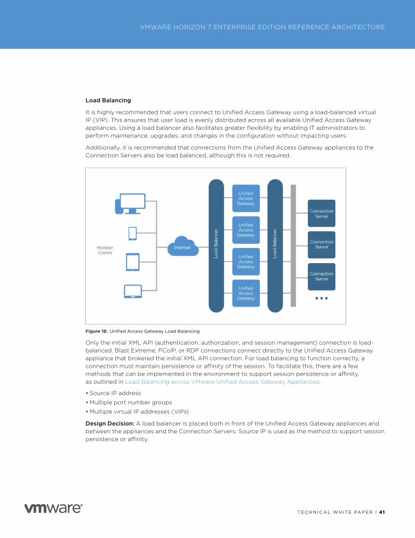
T E C H N I C A L W H I T E PA P E R | 4 1
VMWARE HORIZON 7 ENTERPRISE EDITION REFERENCE ARCHITECTURE
T E C H N I C A L W H I T E PA P E R | 4 1
Load Balancing
It is highly recommended that users connect to Unified Access Gateway using a load-balanced virtual IP (VIP) . This ensures that user load is evenly distributed across all available Unified Access Gateway appliances . Using a load balancer also facilitates greater flexibility by enabling IT administrators to perform maintenance, upgrades, and changes in the configuration without impacting users .
Additionally, it is recommended that connections from the Unified Access Gateway appliances to the Connection Servers also be load balanced, although this is not required .
Figure 18: Unified Access Gateway Load Balancing
Only the initial XML API (authentication, authorization, and session management) connection is load-balanced . Blast Extreme, PCoIP, or RDP connections connect directly to the Unified Access Gateway appliance that brokered the initial XML API connection . For load balancing to function correctly, a connection must maintain persistence or affinity of the session . To facilitate this, there are a few methods that can be implemented in the environment to support session persistence or affinity, as outlined in Load Balancing across VMware Unified Access Gateway Appliances:
• Source IP address
• Multiple port number groups
• Multiple virtual IP addresses (VIPs)
Design Decision: A load balancer is placed both in front of the Unified Access Gateway appliances and between the appliances and the Connection Servers . Source IP is used as the method to support session persistence or affinity .
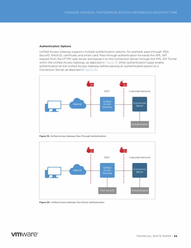
T E C H N I C A L W H I T E PA P E R | 4 2
VMWARE HORIZON 7 ENTERPRISE EDITION REFERENCE ARCHITECTURE
T E C H N I C A L W H I T E PA P E R | 4 2
Authentication Options
Unified Access Gateway supports multiple authentication options, for example, pass-through, RSA SecurID, RADIUS, certificate, and smart card . Pass-through authentication forwards the XML API request from the HTTPS web server and passes it to the Connection Server through the XML API Tunnel within the Unified Access Gateway, as depicted in Figure 19 . Other authentication types enable authentication at the Unified Access Gateway before passing an authenticated session to a Connection Server, as depicted in Figure 20 .
Figure 19: Unified Access Gateway Pass-Through Authentication
Figure 20: Unified Access Gateway Two-Factor Authentication
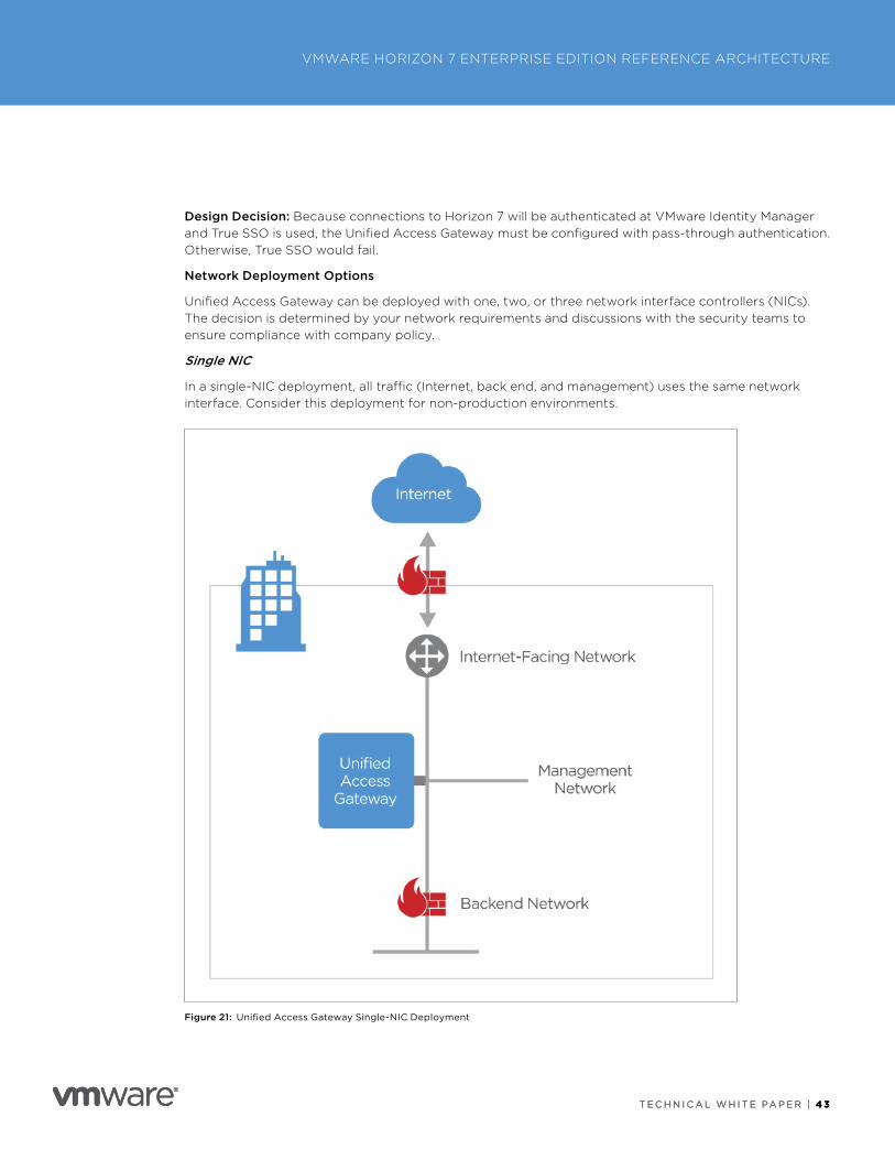
T E C H N I C A L W H I T E PA P E R | 4 3
VMWARE HORIZON 7 ENTERPRISE EDITION REFERENCE ARCHITECTURE
T E C H N I C A L W H I T E PA P E R | 4 3
Design Decision: Because connections to Horizon 7 will be authenticated at VMware Identity Manager and True SSO is used, the Unified Access Gateway must be configured with pass-through authentication . Otherwise, True SSO would fail .
Network Deployment Options
Unified Access Gateway can be deployed with one, two, or three network interface controllers (NICs) . The decision is determined by your network requirements and discussions with the security teams to ensure compliance with company policy .
Single NIC
In a single-NIC deployment, all traffic (Internet, back end, and management) uses the same network interface . Consider this deployment for non-production environments .
Figure 21: Unified Access Gateway Single-NIC Deployment
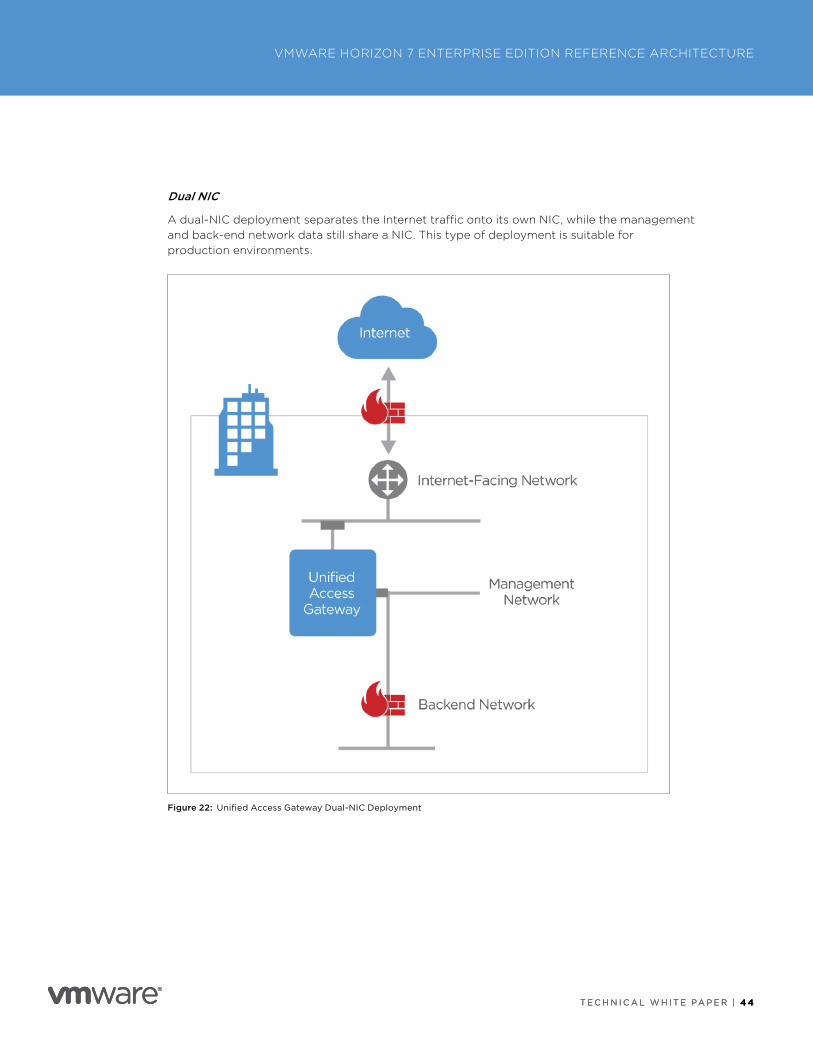
T E C H N I C A L W H I T E PA P E R | 4 4
VMWARE HORIZON 7 ENTERPRISE EDITION REFERENCE ARCHITECTURE
T E C H N I C A L W H I T E PA P E R | 4 4
Dual NIC
A dual-NIC deployment separates the Internet traffic onto its own NIC, while the management and back-end network data still share a NIC . This type of deployment is suitable for production environments .
Figure 22: Unified Access Gateway Dual-NIC Deployment
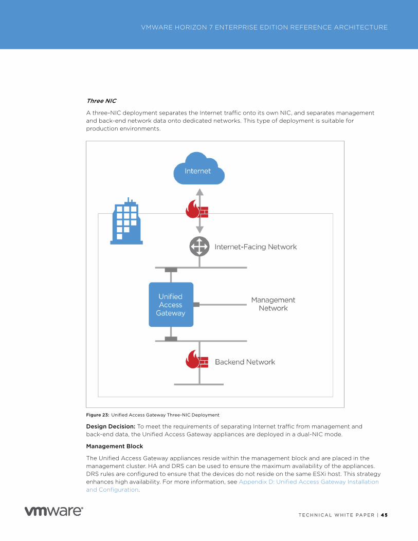
T E C H N I C A L W H I T E PA P E R | 4 5
VMWARE HORIZON 7 ENTERPRISE EDITION REFERENCE ARCHITECTURE
T E C H N I C A L W H I T E PA P E R | 4 5
Three NIC
A three-NIC deployment separates the Internet traffic onto its own NIC, and separates management and back-end network data onto dedicated networks . This type of deployment is suitable for production environments .
Figure 23: Unified Access Gateway Three-NIC Deployment
Design Decision: To meet the requirements of separating Internet traffic from management and back-end data, the Unified Access Gateway appliances are deployed in a dual-NIC mode .
Management Block
The Unified Access Gateway appliances reside within the management block and are placed in the management cluster . HA and DRS can be used to ensure the maximum availability of the appliances . DRS rules are configured to ensure that the devices do not reside on the same ESXi host . This strategy enhances high availability . For more information, see Appendix D: Unified Access Gateway Installation and Configuration .
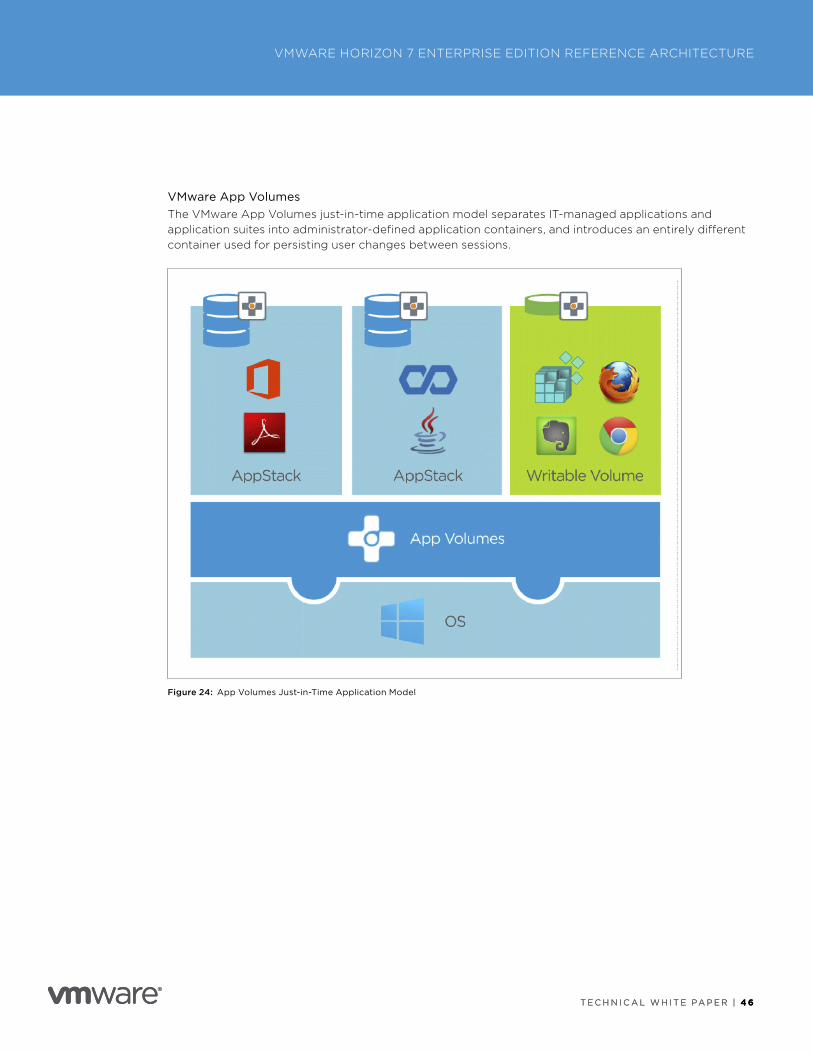
T E C H N I C A L W H I T E PA P E R | 4 6
VMWARE HORIZON 7 ENTERPRISE EDITION REFERENCE ARCHITECTURE
T E C H N I C A L W H I T E PA P E R | 4 6
VMware App VolumesThe VMware App Volumes just-in-time application model separates IT-managed applications and application suites into administrator-defined application containers, and introduces an entirely different container used for persisting user changes between sessions .
Figure 24: App Volumes Just-in-Time Application Model
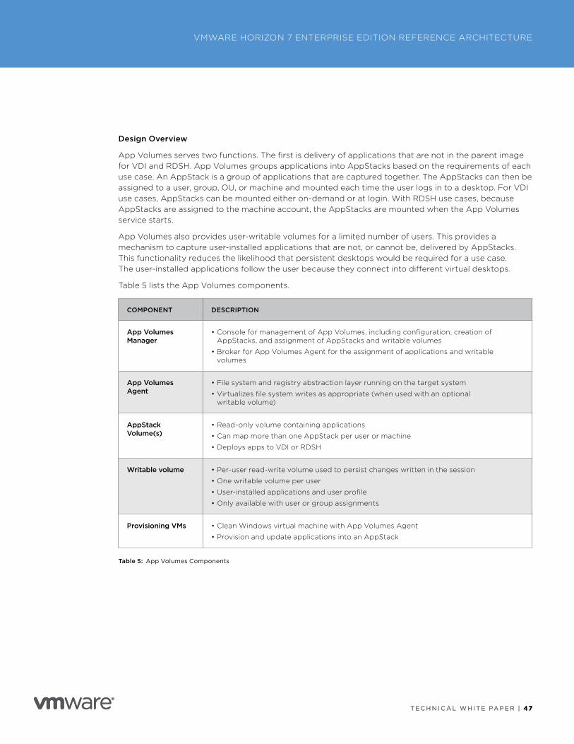
T E C H N I C A L W H I T E PA P E R | 47
VMWARE HORIZON 7 ENTERPRISE EDITION REFERENCE ARCHITECTURE
T E C H N I C A L W H I T E PA P E R | 47
Design Overview
App Volumes serves two functions . The first is delivery of applications that are not in the parent image for VDI and RDSH . App Volumes groups applications into AppStacks based on the requirements of each use case . An AppStack is a group of applications that are captured together . The AppStacks can then be assigned to a user, group, OU, or machine and mounted each time the user logs in to a desktop . For VDI use cases, AppStacks can be mounted either on-demand or at login . With RDSH use cases, because AppStacks are assigned to the machine account, the AppStacks are mounted when the App Volumes service starts .
App Volumes also provides user-writable volumes for a limited number of users . This provides a mechanism to capture user-installed applications that are not, or cannot be, delivered by AppStacks . This functionality reduces the likelihood that persistent desktops would be required for a use case . The user-installed applications follow the user because they connect into different virtual desktops .
Table 5 lists the App Volumes components .
COMPONENT DESCRIPTION
App Volumes Manager
• Console for management of App Volumes, including configuration, creation of AppStacks, and assignment of AppStacks and writable volumes
• Broker for App Volumes Agent for the assignment of applications and writable volumes
App Volumes Agent
• File system and registry abstraction layer running on the target system
• Virtualizes file system writes as appropriate (when used with an optional writable volume)
AppStack Volume(s)
• Read-only volume containing applications
• Can map more than one AppStack per user or machine
• Deploys apps to VDI or RDSH
Writable volume • Per-user read-write volume used to persist changes written in the session
• One writable volume per user
• User-installed applications and user profile
• Only available with user or group assignments
Provisioning VMs • Clean Windows virtual machine with App Volumes Agent
• Provision and update applications into an AppStack
Table 5: App Volumes Components
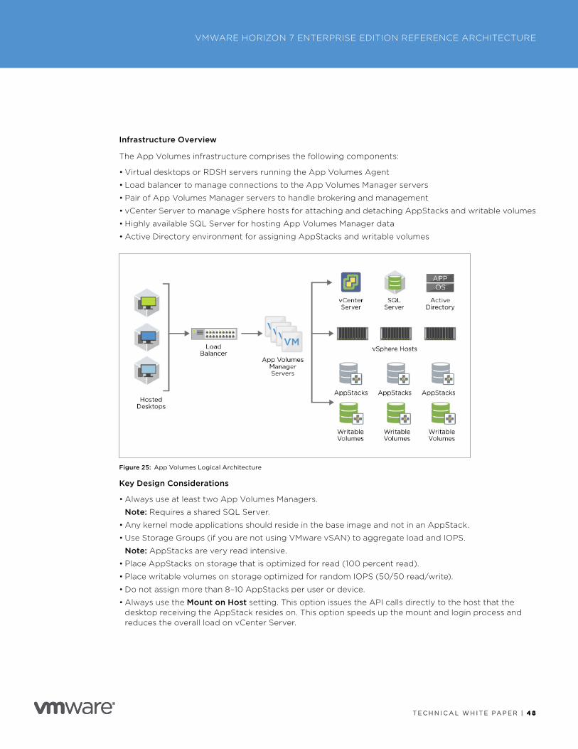
T E C H N I C A L W H I T E PA P E R | 4 8
VMWARE HORIZON 7 ENTERPRISE EDITION REFERENCE ARCHITECTURE
T E C H N I C A L W H I T E PA P E R | 4 8
Infrastructure Overview
The App Volumes infrastructure comprises the following components:
• Virtual desktops or RDSH servers running the App Volumes Agent
• Load balancer to manage connections to the App Volumes Manager servers
• Pair of App Volumes Manager servers to handle brokering and management
• vCenter Server to manage vSphere hosts for attaching and detaching AppStacks and writable volumes
• Highly available SQL Server for hosting App Volumes Manager data
• Active Directory environment for assigning AppStacks and writable volumes
Figure 25: App Volumes Logical Architecture
Key Design Considerations
• Always use at least two App Volumes Managers .
Note: Requires a shared SQL Server .
• Any kernel mode applications should reside in the base image and not in an AppStack .
• Use Storage Groups (if you are not using VMware vSAN) to aggregate load and IOPS .
Note: AppStacks are very read intensive .
• Place AppStacks on storage that is optimized for read (100 percent read) .
• Place writable volumes on storage optimized for random IOPS (50/50 read/write) .
• Do not assign more than 8–10 AppStacks per user or device .
• Always use the Mount on Host setting . This option issues the API calls directly to the host that the desktop receiving the AppStack resides on . This option speeds up the mount and login process and reduces the overall load on vCenter Server .
T E C H N I C A L W H I T E PA P E R | 4 9
VMWARE HORIZON 7 ENTERPRISE EDITION REFERENCE ARCHITECTURE
T E C H N I C A L W H I T E PA P E R | 4 9
Scalability and Availability of App Volumes Managers
The App Volumes Managers are the primary point of management and configuration, and are used for brokering volumes to agents . For a production environment, deploy at least two App Volumes Manager servers . The main concern with App Volumes Managers is handling login storms . To size this design, we assumed each App Volumes Manager was able to handle 750 users, but the exact number can vary, depending on the load and the specifics of each environment . It is recommended that you test the load and size the number of App Volumes Manager servers appropriately .
The App Volumes Manager is stateless—all of the data required by App Volumes is located in a SQL database . By deploying at least two App Volumes Manager servers, we can ensure the availability of App Volumes services and distribute the user load .
Design Decision: Four VMware App Volumes Manager servers were deployed with a load balancer .
Database
VMware App Volumes 2 .13 uses a Microsoft SQL Server database to store all of the configuration, assignment, and metadata . This database is a critical aspect of the design, and it must be accessible to all of the App Volumes Managers .
Design Decision: The SQL database was placed on a highly available SQL Server, which is installed on a Windows Server Failover Cluster . An Always On availability group achieves automatic failover, and all App Volumes Managers point to the availability group listener for the SQL Server .
For more information, see Appendix I: VMware App Volumes Installation and Configuration .
AppStack Storage
App Volumes uses a construct of Storage Groups . A Storage Group is a collection of datastores that are used to serve AppStacks or distribute writeable volumes . In App Volumes 2 .13, the AppStacks within a Storage Group can be replicated among the peers to ensure that all AppStacks are available . Having a common datastore presented to all hosts in all vCenter Servers allows AppStacks to be replicated across vCenter Servers and datastores .
Note: This design uses vSAN, which provides a single, highly available datastore per vSphere cluster .
Design Decision: Storage Groups are used in this design because there are separate vSAN datastores for the instant-clone pools . AppStacks are automatically replicated between the two datastores by the Storage Group .
Load Balancing
For high performance and availability, an external load balancer is required to balance connections between App Volumes Managers .
Design Decision: A load balancer is placed in front of the App Volumes Manager servers . The load balancer properly distributes load and keeps the services available in the event of an issue with one of the managers .
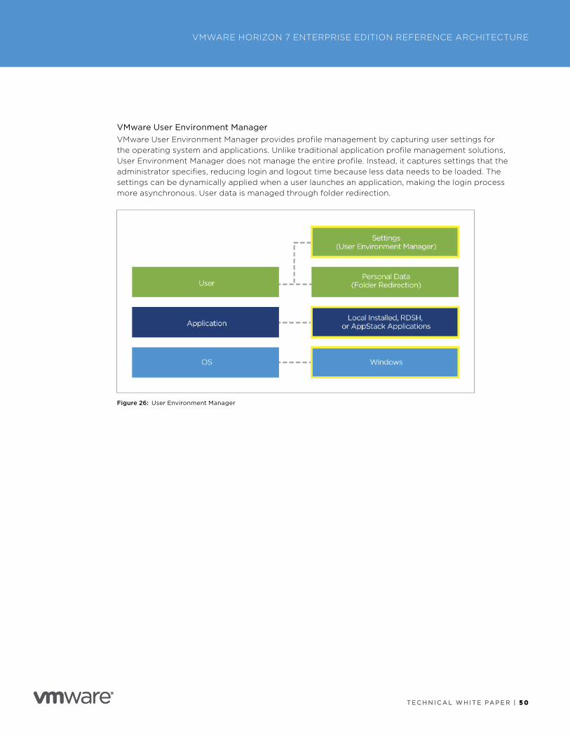
T E C H N I C A L W H I T E PA P E R | 5 0
VMWARE HORIZON 7 ENTERPRISE EDITION REFERENCE ARCHITECTURE
T E C H N I C A L W H I T E PA P E R | 5 0
VMware User Environment ManagerVMware User Environment Manager provides profile management by capturing user settings for the operating system and applications . Unlike traditional application profile management solutions, User Environment Manager does not manage the entire profile . Instead, it captures settings that the administrator specifies, reducing login and logout time because less data needs to be loaded . The settings can be dynamically applied when a user launches an application, making the login process more asynchronous . User data is managed through folder redirection .
Figure 26: User Environment Manager
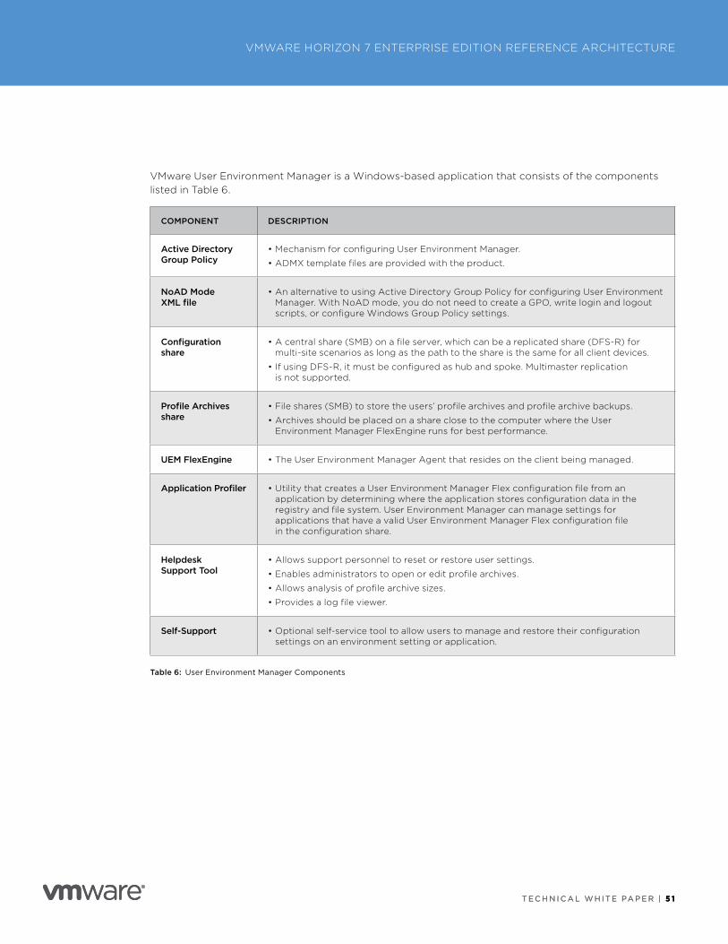
T E C H N I C A L W H I T E PA P E R | 5 1
VMWARE HORIZON 7 ENTERPRISE EDITION REFERENCE ARCHITECTURE
T E C H N I C A L W H I T E PA P E R | 5 1
VMware User Environment Manager is a Windows-based application that consists of the components listed in Table 6 .
COMPONENT DESCRIPTION
Active Directory Group Policy
• Mechanism for configuring User Environment Manager .
• ADMX template files are provided with the product .
NoAD Mode XML file
• An alternative to using Active Directory Group Policy for configuring User Environment Manager . With NoAD mode, you do not need to create a GPO, write login and logout scripts, or configure Windows Group Policy settings .
Configuration share
• A central share (SMB) on a file server, which can be a replicated share (DFS-R) for multi-site scenarios as long as the path to the share is the same for all client devices .
• If using DFS-R, it must be configured as hub and spoke . Multimaster replication is not supported .
Profile Archives share
• File shares (SMB) to store the users’ profile archives and profile archive backups .
• Archives should be placed on a share close to the computer where the User Environment Manager FlexEngine runs for best performance .
UEM FlexEngine • The User Environment Manager Agent that resides on the client being managed .
Application Profiler • Utility that creates a User Environment Manager Flex configuration file from an application by determining where the application stores configuration data in the registry and file system . User Environment Manager can manage settings for applications that have a valid User Environment Manager Flex configuration file in the configuration share .
Helpdesk Support Tool
• Allows support personnel to reset or restore user settings .
• Enables administrators to open or edit profile archives .
• Allows analysis of profile archive sizes .
• Provides a log file viewer .
Self-Support • Optional self-service tool to allow users to manage and restore their configuration settings on an environment setting or application .
Table 6: User Environment Manager Components
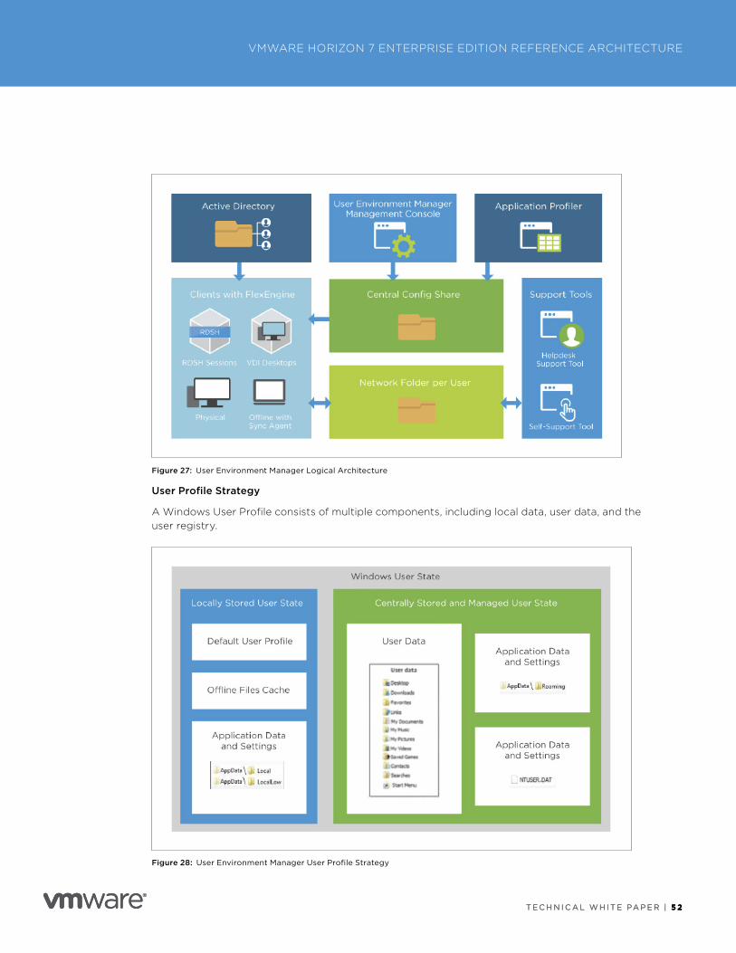
T E C H N I C A L W H I T E PA P E R | 5 2
VMWARE HORIZON 7 ENTERPRISE EDITION REFERENCE ARCHITECTURE
T E C H N I C A L W H I T E PA P E R | 5 2
Figure 27: User Environment Manager Logical Architecture
User Profile Strategy
A Windows User Profile consists of multiple components, including local data, user data, and the user registry .
Figure 28: User Environment Manager User Profile Strategy
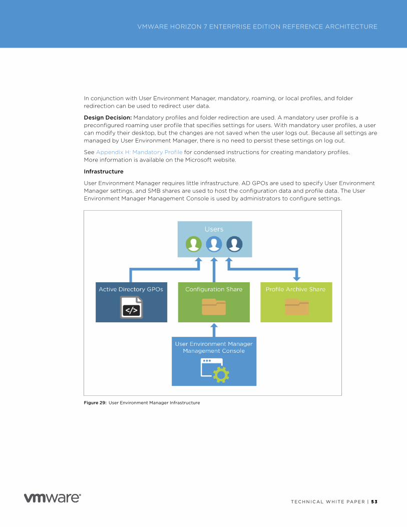
T E C H N I C A L W H I T E PA P E R | 5 3
VMWARE HORIZON 7 ENTERPRISE EDITION REFERENCE ARCHITECTURE
T E C H N I C A L W H I T E PA P E R | 5 3
In conjunction with User Environment Manager, mandatory, roaming, or local profiles, and folder redirection can be used to redirect user data .
Design Decision: Mandatory profiles and folder redirection are used . A mandatory user profile is a preconfigured roaming user profile that specifies settings for users . With mandatory user profiles, a user can modify their desktop, but the changes are not saved when the user logs out . Because all settings are managed by User Environment Manager, there is no need to persist these settings on log out .
See Appendix H: Mandatory Profile for condensed instructions for creating mandatory profiles . More information is available on the Microsoft website .
Infrastructure
User Environment Manager requires little infrastructure . AD GPOs are used to specify User Environment Manager settings, and SMB shares are used to host the configuration data and profile data . The User Environment Manager Management Console is used by administrators to configure settings .
Figure 29: User Environment Manager Infrastructure
T E C H N I C A L W H I T E PA P E R | 5 4
VMWARE HORIZON 7 ENTERPRISE EDITION REFERENCE ARCHITECTURE
T E C H N I C A L W H I T E PA P E R | 5 4
Prerequisites
• Create SMB file shares for configuration data and user data .
• Import ADMX templates for User Environment Manager .
• Create Group Policy settings for User Environment Manager .
• Install the FlexEngine agent on the clients to be managed .
• Install the User Environment Manager Management Console, and point to the configuration share .
• Use Easy Start to do initial configuration of many common Windows environment and application settings . Easy Start provides many application templates, including for various versions of Microsoft Office .
Key Design Considerations
• Use DFS-R or file server clustering to provide HA to configuration and user shares .
– DFS-R can only be hub and spoke . Multimaster replication is not supported .
– See the Microsoft KB article Microsoft’s Support Statement Around Replicated User Profile Data for supported scenarios .
• Use loopback processing when applying the GPO settings to computer objects .
Install
Refer to the User Environment Manager Administrator’s Guide for detailed installation procedures . This reference architecture uses User Environment Manager 9 .2 .1 .
Next Steps
After installing User Environment Manager, perform the following tasks to verify functionality:
• Install User Environment Manager Agent on one or more clients .
• Set a few customizations (for example, desktop shortcuts for VLC and Notepad++) .
• Log in to the client and verify that User Environment Manager has made the requested changes .
• Check the user log to verify that User Environment Manager is working, or to troubleshoot . The logs folder is in the SMB share specified for user data .
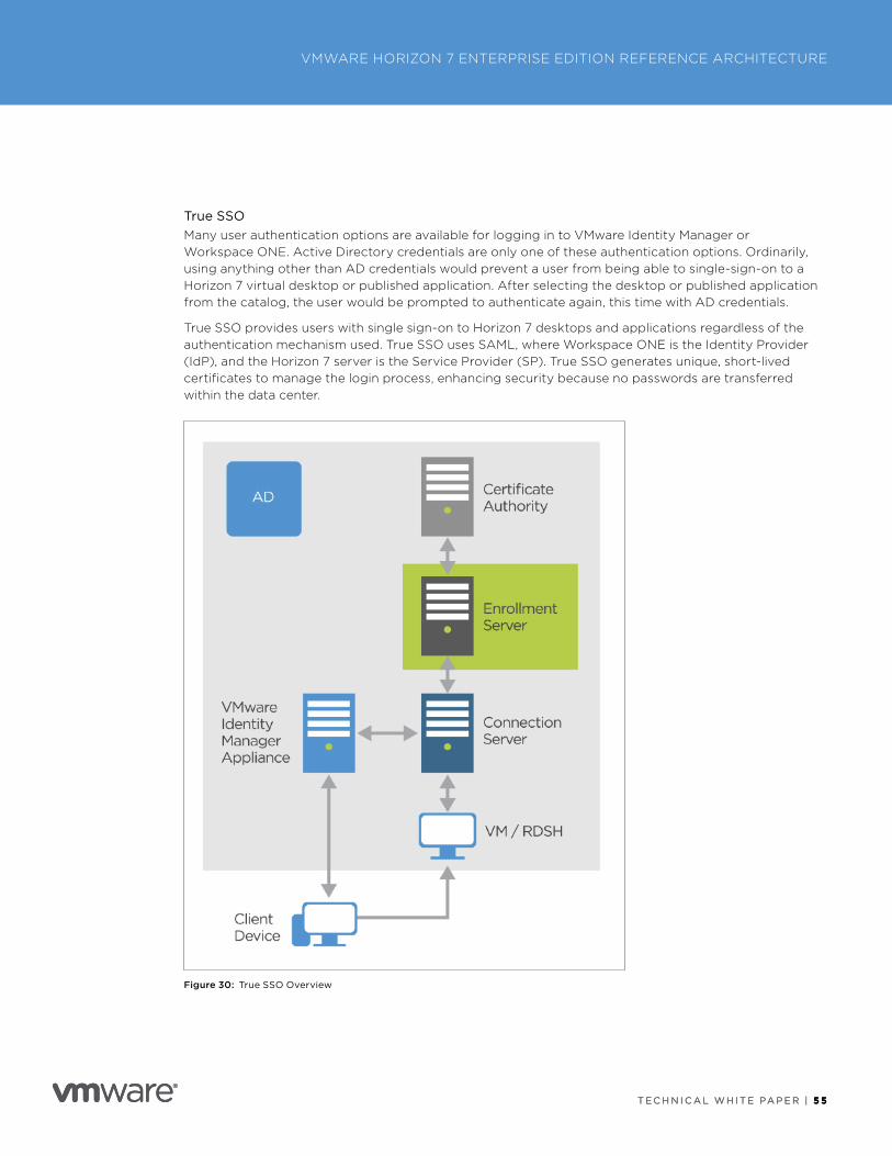
T E C H N I C A L W H I T E PA P E R | 5 5
VMWARE HORIZON 7 ENTERPRISE EDITION REFERENCE ARCHITECTURE
T E C H N I C A L W H I T E PA P E R | 5 5
True SSOMany user authentication options are available for logging in to VMware Identity Manager or Workspace ONE . Active Directory credentials are only one of these authentication options . Ordinarily, using anything other than AD credentials would prevent a user from being able to single-sign-on to a Horizon 7 virtual desktop or published application . After selecting the desktop or published application from the catalog, the user would be prompted to authenticate again, this time with AD credentials .
True SSO provides users with single sign-on to Horizon 7 desktops and applications regardless of the authentication mechanism used . True SSO uses SAML, where Workspace ONE is the Identity Provider (IdP), and the Horizon 7 server is the Service Provider (SP) . True SSO generates unique, short-lived certificates to manage the login process, enhancing security because no passwords are transferred within the data center .
Figure 30: True SSO Overview
T E C H N I C A L W H I T E PA P E R | 5 6
VMWARE HORIZON 7 ENTERPRISE EDITION REFERENCE ARCHITECTURE
T E C H N I C A L W H I T E PA P E R | 5 6
True SSO requires a new service—the enrollment server—to be installed using the Horizon 7 installation media . The enrollment server can be installed on a dedicated Windows 2016 server, or it can co-exist on the server running the MS Certificate Authority service .
Design Overview
For True SSO to function, several components must be installed and configured within the environment . The following sections discuss the design options and detail the design decisions that satisfy the requirements .
Note: For more information on how to install and configure True SSO, see Setting Up True SSO in the View Administration guide .
Enrollment Server
The enrollment server is responsible for receiving certificate signing requests from the Connection Server and then passing them to the Certificate Authority to sign using the relevant certificate template .
Scalability
The enrollment server is a lightweight service that can be installed on a dedicated Windows 2016 server, or it can co-exist with the MS Certificate Authority .
A single enrollment server can easily handle all the requests from a single pod .
To satisfy the requirements that the proposed solution be robust and able to handle failure, we deploy n+1 enrollment servers .
Design Decision: Two enrollment servers are deployed within a pod to satisfy the requirement of 2,000 sessions and high availability . Each enrollment server is hosted on a dedicated Windows 2016 VM .
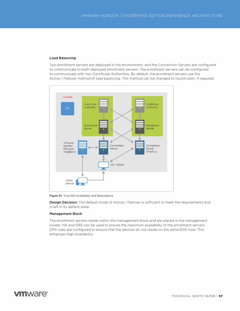
T E C H N I C A L W H I T E PA P E R | 5 7
VMWARE HORIZON 7 ENTERPRISE EDITION REFERENCE ARCHITECTURE
T E C H N I C A L W H I T E PA P E R | 5 7
Load Balancing
Two enrollment servers are deployed in the environment, and the Connection Servers are configured to communicate to both deployed enrollment servers . The enrollment servers can be configured to communicate with two Certificate Authorities . By default, the enrollment servers use the Active / Failover method of load balancing . This method can be changed to round robin, if required .
Figure 31: True SSO Availability and Redundancy
Design Decision: The default mode of Active / Failover is sufficient to meet the requirements and is left in its default state .
Management Block
The enrollment servers reside within the management block and are placed in the management cluster . HA and DRS can be used to ensure the maximum availability of the enrollment servers . DRS rules are configured to ensure that the devices do not reside on the same ESXi host . This enhances High Availability .
T E C H N I C A L W H I T E PA P E R | 5 8
VMWARE HORIZON 7 ENTERPRISE EDITION REFERENCE ARCHITECTURE
T E C H N I C A L W H I T E PA P E R | 5 8
VMware vRealize Operations Manager for HorizonTraditionally, management and monitoring of enterprise environments involved monitoring a bewildering array of systems, requiring administrators to switch between multiple consoles to support the environment .
VMware vRealize Operations for Horizon provides end-to-end visibility of VMware Horizon and its supporting infrastructure, enabling administrators to:
• Meet service-level agreements (SLAs)
• Reduce the first time to resolution (FTR)
• Improve user satisfaction
• Proactively monitor the environment, and resolve issues before they affect users
• Optimize resources, and lower management costs
• Monitor reporting
• Create custom dashboards
Design Overview
VMware vRealize Operations for Horizon facilitates proactive monitoring and management of a VMware Horizon environment and can also proactively monitor vSphere and display all information, alerts, and warnings for compute, storage, and networking .
VMware vRealize Operations for Horizon consists of two components: the vRealize Operations Manager appliance and the Horizon adapter . Other adapters can be added to the core vRealize Operations Manager appliance to gather information from other sources; for example, the VMware vRealize Operations for Published Applications™ adapter retrieves information from Citrix environments and displays it within the vRealize Operations Manager dashboards .
The latest release of vRealize Operations Manager (6 .5) and the Horizon adapter (6 .5) are used .
Design Decision: To meet the customer requirements, the vRealize Operations Manager for Horizon appliance and the Horizon adapter are used .
Deployment Options
VMware vRealize Operations Manager can be deployed on either Windows or Linux . It can also be deployed as a self-contained appliance .
VMware vRealize Operations Manager can be deployed as a single node, as part of a cluster, or as a cluster with remote nodes .
• Single Node – A single-node deployment does not provide high availability and is limited in the number of objects that it can support .
• Cluster – A cluster can consist of up to eight nodes (appliances) . This configuration provides flexibility and the ability to scale to suit most customer deployments while providing high availability .
• Cluster + Remote Node – A remote node is deployed on a remote site or data center to capture information before compressing and passing it back to the cluster for processing . Remote nodes can also be used within the same data center as the cluster and have adapters installed on them instead of the cluster nodes, freeing the cluster nodes to handle the analytical processing .
Design Decision: The vRealize Operations Manager appliances are deployed as part of a cluster to meet the requirements .
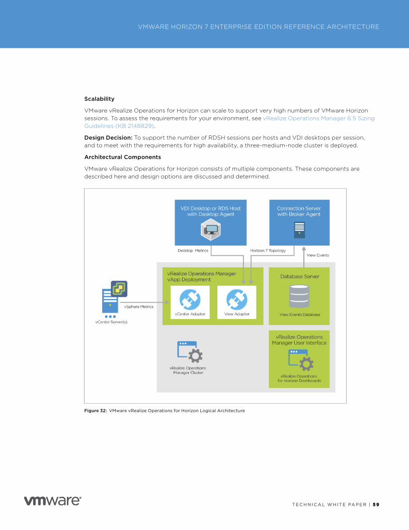
T E C H N I C A L W H I T E PA P E R | 5 9
VMWARE HORIZON 7 ENTERPRISE EDITION REFERENCE ARCHITECTURE
T E C H N I C A L W H I T E PA P E R | 5 9
Scalability
VMware vRealize Operations for Horizon can scale to support very high numbers of VMware Horizon sessions . To assess the requirements for your environment, see vRealize Operations Manager 6 .5 Sizing Guidelines (KB 2148829) .
Design Decision: To support the number of RDSH sessions per hosts and VDI desktops per session, and to meet with the requirements for high availability, a three-medium-node cluster is deployed .
Architectural Components
VMware vRealize Operations for Horizon consists of multiple components . These components are described here and design options are discussed and determined .
Figure 32: VMware vRealize Operations for Horizon Logical Architecture
T E C H N I C A L W H I T E PA P E R | 6 0
VMWARE HORIZON 7 ENTERPRISE EDITION REFERENCE ARCHITECTURE
T E C H N I C A L W H I T E PA P E R | 6 0
Broker Agent
The broker agent is a Windows service that runs on a Connection Server host that collects Horizon 7 inventory information, and then sends that information to the vRealize Operations Manager Horizon adapter .
• The broker agent collects information from the event database and sends it to the Horizon adapter .
• The broker agent is installed on one Connection Server host in each View pod .
• Only one broker agent exists in each View pod .
• Connection Server 6 .0 .1 or later is required . We used Connection Server 7 .3 .2 .
• .NET Framework 4 .5 is required .
Design Decision: The broker agent is configured to collect information from the event database . It is deployed to a single Connection Server within the pod .
Horizon Adapter
The adapter passes data from the agents to vRealize Operations Manager for analysis and visualization . It also obtains inventory information from the broker agent and collects metrics and performance data from desktop agents . Horizon adapters do not support HA . In the event of a failure, data will not be collected until the issue is resolved, and the adapter is brought back online .
Design Decision: Install the Horizon adapter on one of the cluster nodes .
Desktop Agent
The vRealize Operations for Horizon desktop agent runs on each remote desktop VM or RDS host in the Horizon 7 environment . The desktop agent is included in the Horizon Agent installer . It collects metrics and performance data and sends that data to the Horizon adapter . Metrics collected by the desktop agent include:
• Desktop and application objects
• Users’ login time and duration
• Session duration
• Resource and protocol information
Design Decision: The desktop agent is installed as part of the standard Horizon Agent and is enabled during installation .
Firewall Ports
To support a successful installation, the following firewall ports must be open bidirectionally between:
• Connection Server (broker agent) and the vRealize Operations node: TCP 3091, 3101, and 3100
• Horizon Agents and the vRealize Operations node: TCP 3091 and 3099
See Create an Instance of the Horizon Adapter in the vRealize Operations for Horizon Installation guide for more detail .
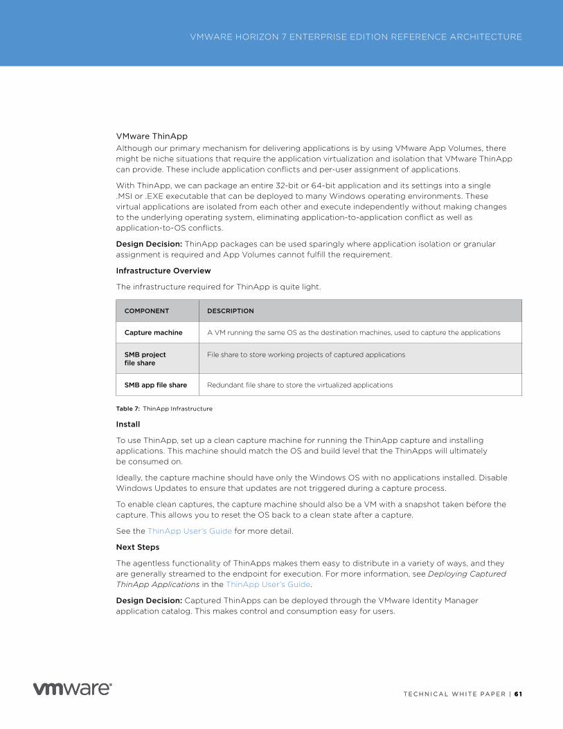
T E C H N I C A L W H I T E PA P E R | 6 1
VMWARE HORIZON 7 ENTERPRISE EDITION REFERENCE ARCHITECTURE
T E C H N I C A L W H I T E PA P E R | 6 1
VMware ThinAppAlthough our primary mechanism for delivering applications is by using VMware App Volumes, there might be niche situations that require the application virtualization and isolation that VMware ThinApp can provide . These include application conflicts and per-user assignment of applications .
With ThinApp, we can package an entire 32-bit or 64-bit application and its settings into a single .MSI or .EXE executable that can be deployed to many Windows operating environments . These virtual applications are isolated from each other and execute independently without making changes to the underlying operating system, eliminating application-to-application conflict as well as application-to-OS conflicts .
Design Decision: ThinApp packages can be used sparingly where application isolation or granular assignment is required and App Volumes cannot fulfill the requirement .
Infrastructure Overview
The infrastructure required for ThinApp is quite light .
COMPONENT DESCRIPTION
Capture machine A VM running the same OS as the destination machines, used to capture the applications
SMB project file share
File share to store working projects of captured applications
SMB app file share Redundant file share to store the virtualized applications
Table 7: ThinApp Infrastructure
Install
To use ThinApp, set up a clean capture machine for running the ThinApp capture and installing applications . This machine should match the OS and build level that the ThinApps will ultimately be consumed on .
Ideally, the capture machine should have only the Windows OS with no applications installed . Disable Windows Updates to ensure that updates are not triggered during a capture process .
To enable clean captures, the capture machine should also be a VM with a snapshot taken before the capture . This allows you to reset the OS back to a clean state after a capture .
See the ThinApp User’s Guide for more detail .
Next Steps
The agentless functionality of ThinApps makes them easy to distribute in a variety of ways, and they are generally streamed to the endpoint for execution . For more information, see Deploying Captured ThinApp Applications in the ThinApp User’s Guide .
Design Decision: Captured ThinApps can be deployed through the VMware Identity Manager application catalog . This makes control and consumption easy for users .
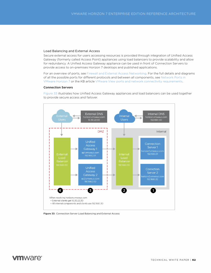
T E C H N I C A L W H I T E PA P E R | 6 2
VMWARE HORIZON 7 ENTERPRISE EDITION REFERENCE ARCHITECTURE
T E C H N I C A L W H I T E PA P E R | 6 2
Load Balancing and External AccessSecure external access for users accessing resources is provided through integration of Unified Access Gateway (formerly called Access Point) appliances using load balancers to provide scalability and allow for redundancy . A Unified Access Gateway appliance can be used in front of Connection Servers to provide access to on-premises Horizon 7 desktops and published applications .
For an overview of ports, see Firewall and External Access Networking . For the full details and diagrams of all the possible ports for different protocols and between all components, see Network Ports in VMware Horizon 7 or the KB article VMware View ports and network connectivity requirements .
Connection Servers
Figure 33 illustrates how Unified Access Gateway appliances and load balancers can be used together to provide secure access and failover .
Figure 33: Connection Server Load Balancing and External Access
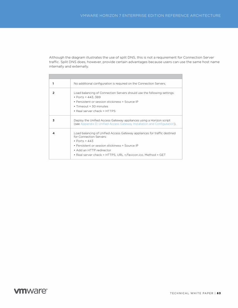
T E C H N I C A L W H I T E PA P E R | 6 3
VMWARE HORIZON 7 ENTERPRISE EDITION REFERENCE ARCHITECTURE
T E C H N I C A L W H I T E PA P E R | 6 3
Although the diagram illustrates the use of split DNS, this is not a requirement for Connection Server traffic . Split DNS does, however, provide certain advantages because users can use the same host name internally and externally .
1 No additional configuration is required on the Connection Servers .
2 Load balancing of Connection Servers should use the following settings:• Ports = 443, 389
• Persistent or session stickiness = Source IP
• Timeout = 30 minutes
• Real server check = HTTPS
3 Deploy the Unified Access Gateway appliances using a Horizon script (see Appendix D: Unified Access Gateway Installation and Configuration) .
4 Load balancing of Unified Access Gateway appliances for traffic destined for Connection Servers:• Ports = 443
• Persistent or session stickiness = Source IP
• Add an HTTP redirector
• Real server check = HTTPS, URL =/favicon .ico, Method = GET
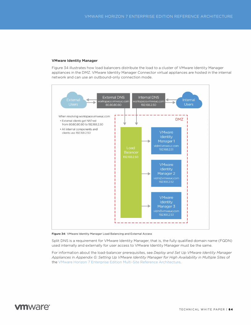
T E C H N I C A L W H I T E PA P E R | 6 4
VMWARE HORIZON 7 ENTERPRISE EDITION REFERENCE ARCHITECTURE
T E C H N I C A L W H I T E PA P E R | 6 4
VMware Identity Manager
Figure 34 illustrates how load balancers distribute the load to a cluster of VMware Identity Manager appliances in the DMZ . VMware Identity Manager Connector virtual appliances are hosted in the internal network and can use an outbound-only connection mode .
Figure 34: VMware Identity Manager Load Balancing and External Access
Split DNS is a requirement for VMware Identity Manager, that is, the fully qualified domain name (FQDN) used internally and externally for user access to VMware Identity Manager must be the same .
For information about the load-balancer prerequisites, see Deploy and Set Up VMware Identity Manager Appliances in Appendix G: Setting Up VMware Identity Manager for High Availability in Multiple Sites of the VMware Horizon 7 Enterprise Edition Multi-Site Reference Architecture .
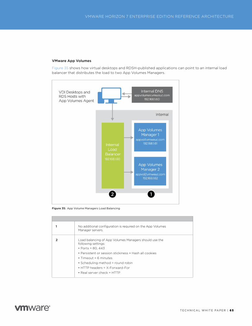
T E C H N I C A L W H I T E PA P E R | 6 5
VMWARE HORIZON 7 ENTERPRISE EDITION REFERENCE ARCHITECTURE
T E C H N I C A L W H I T E PA P E R | 6 5
VMware App Volumes
Figure 35 shows how virtual desktops and RDSH-published applications can point to an internal load balancer that distributes the load to two App Volumes Managers .
Figure 35: App Volume Managers Load Balancing
1 No additional configuration is required on the App Volumes Manager servers .
2 Load balancing of App Volumes Managers should use the following settings:• Ports = 80, 443
• Persistent or session stickiness = Hash all cookies
• Timeout = 6 minutes
• Scheduling method = round robin
• HTTP headers = X-Forward-For
• Real server check = HTTP
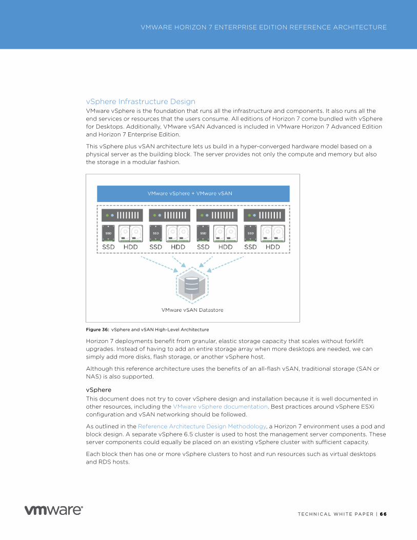
T E C H N I C A L W H I T E PA P E R | 6 6
VMWARE HORIZON 7 ENTERPRISE EDITION REFERENCE ARCHITECTURE
T E C H N I C A L W H I T E PA P E R | 6 6
vSphere Infrastructure DesignVMware vSphere is the foundation that runs all the infrastructure and components . It also runs all the end services or resources that the users consume . All editions of Horizon 7 come bundled with vSphere for Desktops . Additionally, VMware vSAN Advanced is included in VMware Horizon 7 Advanced Edition and Horizon 7 Enterprise Edition .
This vSphere plus vSAN architecture lets us build in a hyper-converged hardware model based on a physical server as the building block . The server provides not only the compute and memory but also the storage in a modular fashion .
Figure 36: vSphere and vSAN High-Level Architecture
Horizon 7 deployments benefit from granular, elastic storage capacity that scales without forklift upgrades . Instead of having to add an entire storage array when more desktops are needed, we can simply add more disks, flash storage, or another vSphere host .
Although this reference architecture uses the benefits of an all-flash vSAN, traditional storage (SAN or NAS) is also supported .
vSphere This document does not try to cover vSphere design and installation because it is well documented in other resources, including the VMware vSphere documentation . Best practices around vSphere ESXi configuration and vSAN networking should be followed .
As outlined in the Reference Architecture Design Methodology, a Horizon 7 environment uses a pod and block design . A separate vSphere 6 .5 cluster is used to host the management server components . These server components could equally be placed on an existing vSphere cluster with sufficient capacity .
Each block then has one or more vSphere clusters to host and run resources such as virtual desktops and RDS hosts .
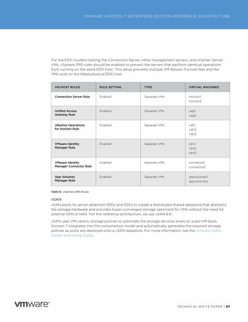
T E C H N I C A L W H I T E PA P E R | 6 7
VMWARE HORIZON 7 ENTERPRISE EDITION REFERENCE ARCHITECTURE
T E C H N I C A L W H I T E PA P E R | 6 7
For the ESXi clusters hosting the Connection Server, other management servers, and vCenter Server VMs, vSphere DRS rules should be enabled to prevent the servers that perform identical operations from running on the same ESXi host . This setup prevents multiple VM failures if a host fails and the VMs exist on the failed physical ESXi host .
VM/HOST RULES RULE SETTING TYPE VIRTUAL MACHINES
Connection Server Rule Enabled Separate VMs horizon1horizon2
Unified Access Gateway Rule
Enabled Separate VMs uag1uag2
vRealize Operations for Horizon Rule
Enabled Separate VMs v4h1v4h2v4h3
VMware Identity Manager Rule
Enabled Separate VMs idm1idm2idm3
VMware Identity Manager Connector Rule
Enabled Separate VMs connector1connector2
App Volumes Manager Rule
Enabled Separate VMs appvolumes1appvolumes2
Table 8: vSphere DRS Rules
vSANvSAN pools its server-attached HDDs and SSDs to create a distributed shared datastore that abstracts the storage hardware and provides hyper-converged storage optimized for VMs without the need for external SAN or NAS . For this reference architecture, we use vSAN 6 .6 .
vSAN uses VM-centric storage policies to automate the storage services levels on a per-VM basis . Horizon 7 integrates into this consumption model and automatically generates the required storage policies as pools are deployed onto a vSAN datastore . For more information, see the VMware vSAN Design and Sizing Guide .
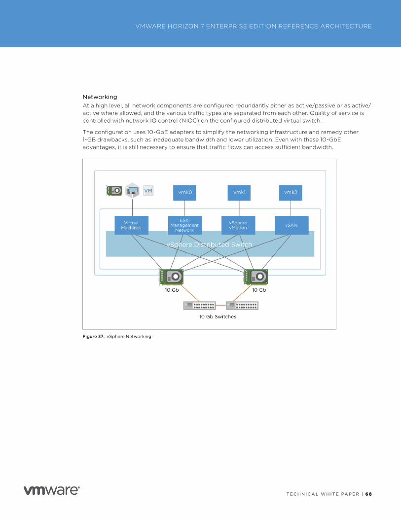
T E C H N I C A L W H I T E PA P E R | 6 8
VMWARE HORIZON 7 ENTERPRISE EDITION REFERENCE ARCHITECTURE
T E C H N I C A L W H I T E PA P E R | 6 8
NetworkingAt a high level, all network components are configured redundantly either as active/passive or as active/active where allowed, and the various traffic types are separated from each other . Quality of service is controlled with network IO control (NIOC) on the configured distributed virtual switch .
The configuration uses 10-GbE adapters to simplify the networking infrastructure and remedy other 1-GB drawbacks, such as inadequate bandwidth and lower utilization . Even with these 10-GbE advantages, it is still necessary to ensure that traffic flows can access sufficient bandwidth .
Figure 37: vSphere Networking
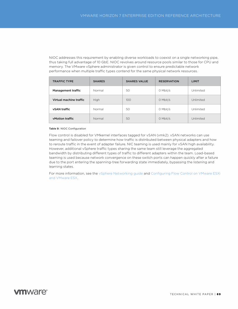
T E C H N I C A L W H I T E PA P E R | 6 9
VMWARE HORIZON 7 ENTERPRISE EDITION REFERENCE ARCHITECTURE
T E C H N I C A L W H I T E PA P E R | 6 9
NIOC addresses this requirement by enabling diverse workloads to coexist on a single networking pipe, thus taking full advantage of 10 GbE . NIOC revolves around resource pools similar to those for CPU and memory . The VMware vSphere administrator is given control to ensure predictable network performance when multiple traffic types contend for the same physical network resources .
TRAFFIC TYPE SHARES SHARES VALUE RESERVATION LIMIT
Management traffic Normal 50 0 Mbit/s Unlimited
Virtual machine traffic High 100 0 Mbit/s Unlimited
vSAN traffic Normal 50 0 Mbit/s Unlimited
vMotion traffic Normal 50 0 Mbit/s Unlimited
Table 9: NIOC Configuration
Flow control is disabled for VMkernel interfaces tagged for vSAN (vmk2) . vSAN networks can use teaming and failover policy to determine how traffic is distributed between physical adapters and how to reroute traffic in the event of adapter failure . NIC teaming is used mainly for vSAN high availability . However, additional vSphere traffic types sharing the same team still leverage the aggregated bandwidth by distributing different types of traffic to different adapters within the team . Load-based teaming is used because network convergence on these switch ports can happen quickly after a failure due to the port entering the spanning-tree forwarding state immediately, bypassing the listening and learning states .
For more information, see the vSphere Networking guide and Configuring Flow Control on VMware ESXi and VMware ESX .
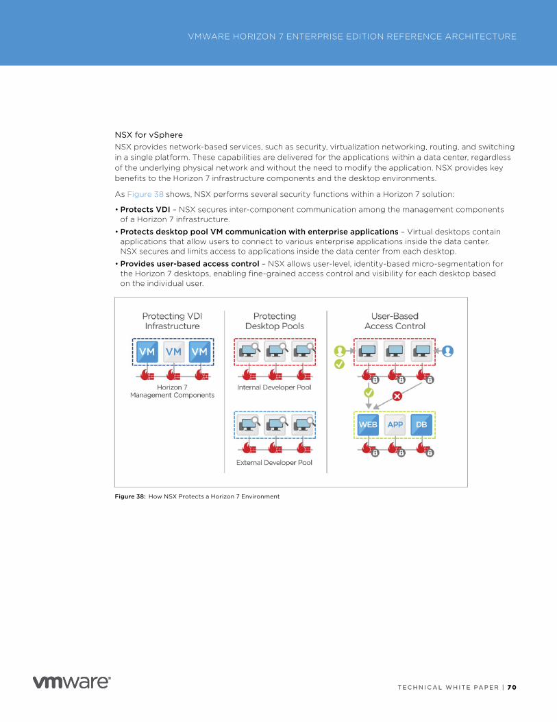
T E C H N I C A L W H I T E PA P E R | 7 0
VMWARE HORIZON 7 ENTERPRISE EDITION REFERENCE ARCHITECTURE
T E C H N I C A L W H I T E PA P E R | 7 0
NSX for vSphereNSX provides network-based services, such as security, virtualization networking, routing, and switching in a single platform . These capabilities are delivered for the applications within a data center, regardless of the underlying physical network and without the need to modify the application . NSX provides key benefits to the Horizon 7 infrastructure components and the desktop environments .
As Figure 38 shows, NSX performs several security functions within a Horizon 7 solution:
• Protects VDI – NSX secures inter-component communication among the management components of a Horizon 7 infrastructure .
• Protects desktop pool VM communication with enterprise applications – Virtual desktops contain applications that allow users to connect to various enterprise applications inside the data center . NSX secures and limits access to applications inside the data center from each desktop .
• Provides user-based access control – NSX allows user-level, identity-based micro-segmentation for the Horizon 7 desktops, enabling fine-grained access control and visibility for each desktop based on the individual user .
Figure 38: How NSX Protects a Horizon 7 Environment
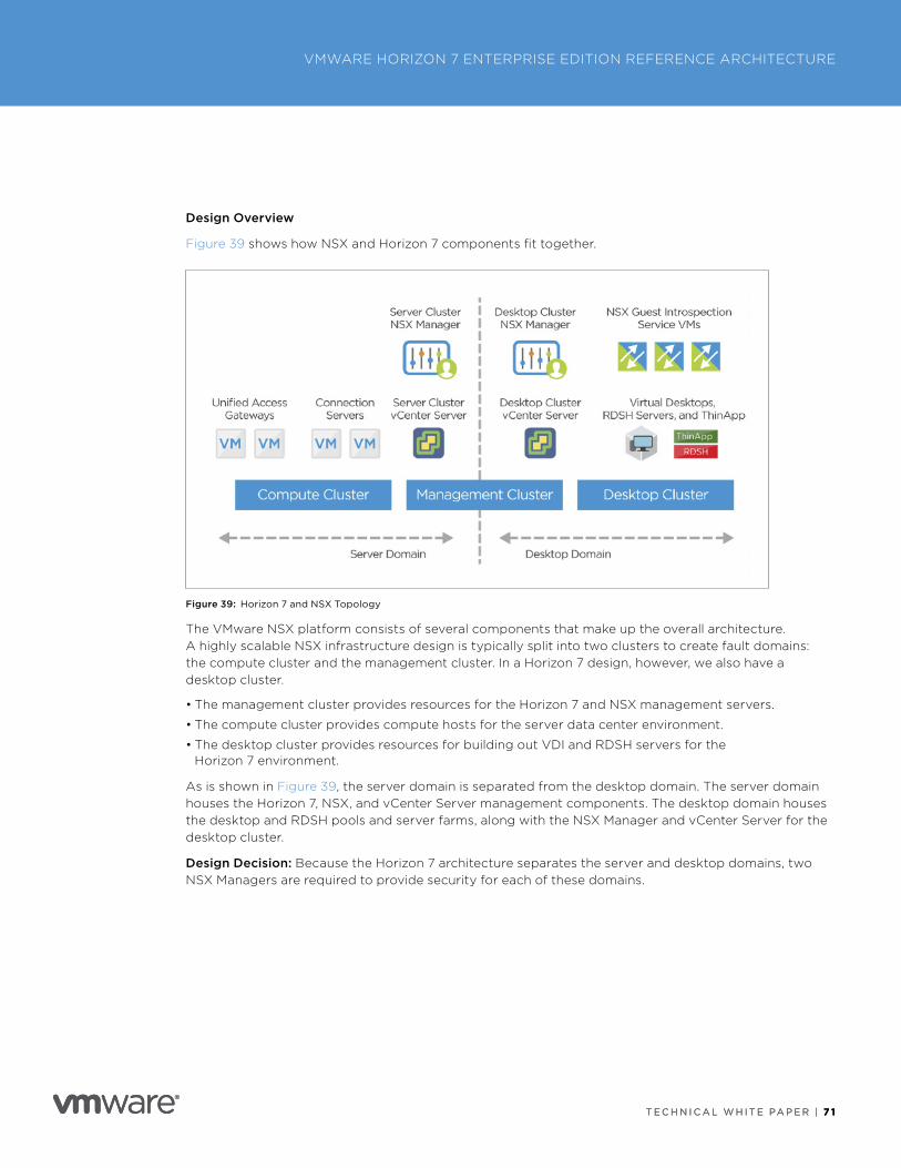
T E C H N I C A L W H I T E PA P E R | 7 1
VMWARE HORIZON 7 ENTERPRISE EDITION REFERENCE ARCHITECTURE
T E C H N I C A L W H I T E PA P E R | 7 1
Design Overview
Figure 39 shows how NSX and Horizon 7 components fit together .
Figure 39: Horizon 7 and NSX Topology
The VMware NSX platform consists of several components that make up the overall architecture . A highly scalable NSX infrastructure design is typically split into two clusters to create fault domains: the compute cluster and the management cluster . In a Horizon 7 design, however, we also have a desktop cluster .
• The management cluster provides resources for the Horizon 7 and NSX management servers .
• The compute cluster provides compute hosts for the server data center environment .
• The desktop cluster provides resources for building out VDI and RDSH servers for the Horizon 7 environment .
As is shown in Figure 39, the server domain is separated from the desktop domain . The server domain houses the Horizon 7, NSX, and vCenter Server management components . The desktop domain houses the desktop and RDSH pools and server farms, along with the NSX Manager and vCenter Server for the desktop cluster .
Design Decision: Because the Horizon 7 architecture separates the server and desktop domains, two NSX Managers are required to provide security for each of these domains .
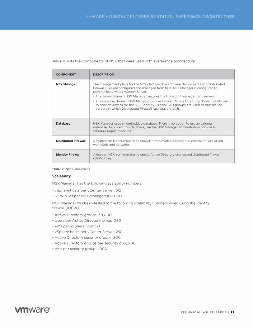
T E C H N I C A L W H I T E PA P E R | 7 2
VMWARE HORIZON 7 ENTERPRISE EDITION REFERENCE ARCHITECTURE
T E C H N I C A L W H I T E PA P E R | 7 2
Table 10 lists the components of NSX that were used in this reference architecture .
COMPONENT DESCRIPTION
NSX Manager The management plane for the NSX platform . The software deployments and Distributed Firewall rules are configured and managed from here . NSX Manager is configured to communicate with a vCenter Server . • The server domain NSX Manager secures the Horizon 7 management servers .
• The desktop domain NSX Manager connects to an Active Directory domain controller to provide access for the NSX Identity Firewall . AD groups are used to provide the objects in which Distributed Firewall rule sets are built .
Database NSX Manager uses an embedded database . There is no option to use an external database . To protect this database, use the NSX Manager administration console to schedule regular backups .
Distributed Firewall A hypervisor kernel-embedded firewall that provides visibility and control for virtualized workloads and networks .
Identity Firewall Allows an NSX administrator to create Active Directory user-based distributed firewall (DFW) rules .
Table 10: NSX Components
Scalability
NSX Manager has the following scalability numbers:
• vSphere hosts per vCenter Server: 512
• DFW rules per NSX Manager: 100,000
NSX Manager has been tested to the following scalability numbers when using the identity firewall (IDFW):
• Active Directory groups: 30,000
• Users per Active Directory group: 250
• VMs per vSphere host: 50
• vSphere hosts per vCenter Server: 250
• Active Directory security groups: 300
• Active Directory groups per security group: 10
• VMs per security group: 1,000
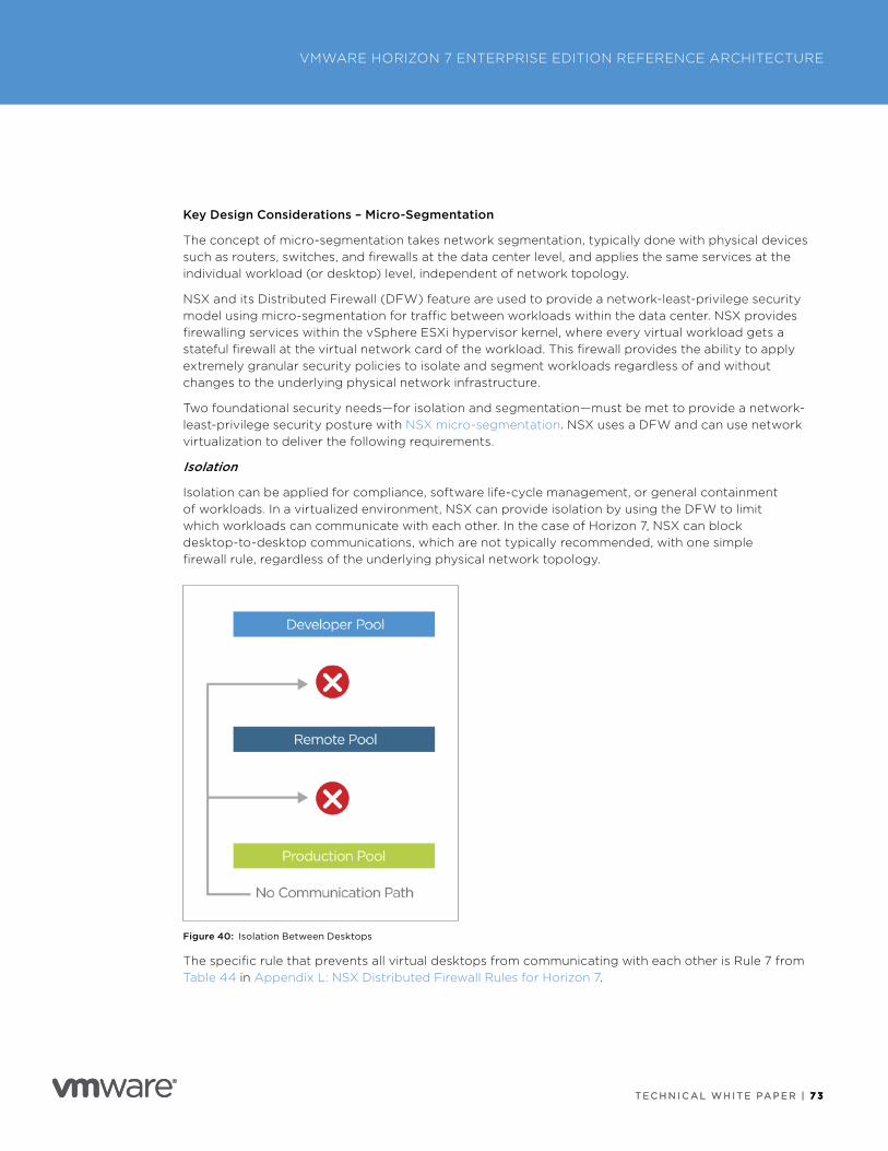
T E C H N I C A L W H I T E PA P E R | 7 3
VMWARE HORIZON 7 ENTERPRISE EDITION REFERENCE ARCHITECTURE
T E C H N I C A L W H I T E PA P E R | 7 3
Key Design Considerations – Micro-Segmentation
The concept of micro-segmentation takes network segmentation, typically done with physical devices such as routers, switches, and firewalls at the data center level, and applies the same services at the individual workload (or desktop) level, independent of network topology .
NSX and its Distributed Firewall (DFW) feature are used to provide a network-least-privilege security model using micro-segmentation for traffic between workloads within the data center . NSX provides firewalling services within the vSphere ESXi hypervisor kernel, where every virtual workload gets a stateful firewall at the virtual network card of the workload . This firewall provides the ability to apply extremely granular security policies to isolate and segment workloads regardless of and without changes to the underlying physical network infrastructure .
Two foundational security needs—for isolation and segmentation—must be met to provide a network-least-privilege security posture with NSX micro-segmentation . NSX uses a DFW and can use network virtualization to deliver the following requirements .
Isolation
Isolation can be applied for compliance, software life-cycle management, or general containment of workloads . In a virtualized environment, NSX can provide isolation by using the DFW to limit which workloads can communicate with each other . In the case of Horizon 7, NSX can block desktop-to-desktop communications, which are not typically recommended, with one simple firewall rule, regardless of the underlying physical network topology .
Figure 40: Isolation Between Desktops
The specific rule that prevents all virtual desktops from communicating with each other is Rule 7 from Table 44 in Appendix L: NSX Distributed Firewall Rules for Horizon 7 .
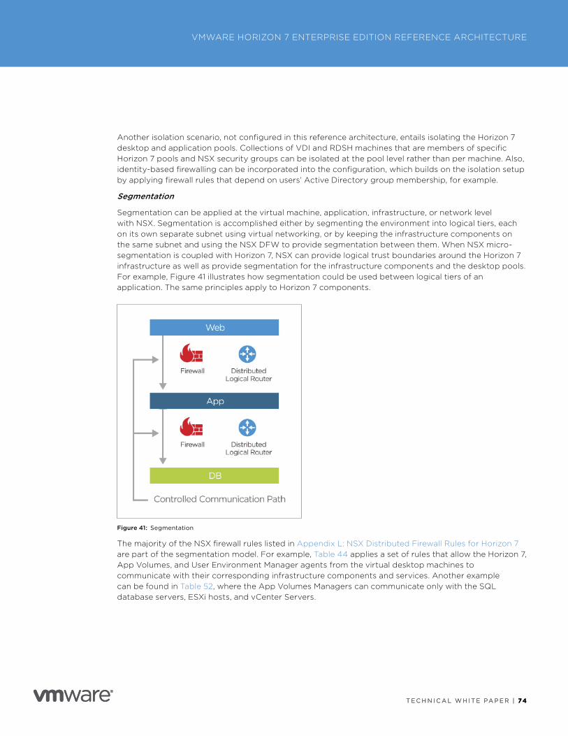
T E C H N I C A L W H I T E PA P E R | 74
VMWARE HORIZON 7 ENTERPRISE EDITION REFERENCE ARCHITECTURE
T E C H N I C A L W H I T E PA P E R | 74
Another isolation scenario, not configured in this reference architecture, entails isolating the Horizon 7 desktop and application pools . Collections of VDI and RDSH machines that are members of specific Horizon 7 pools and NSX security groups can be isolated at the pool level rather than per machine . Also, identity-based firewalling can be incorporated into the configuration, which builds on the isolation setup by applying firewall rules that depend on users’ Active Directory group membership, for example .
Segmentation
Segmentation can be applied at the virtual machine, application, infrastructure, or network level with NSX . Segmentation is accomplished either by segmenting the environment into logical tiers, each on its own separate subnet using virtual networking, or by keeping the infrastructure components on the same subnet and using the NSX DFW to provide segmentation between them . When NSX micro-segmentation is coupled with Horizon 7, NSX can provide logical trust boundaries around the Horizon 7 infrastructure as well as provide segmentation for the infrastructure components and the desktop pools . For example, Figure 41 illustrates how segmentation could be used between logical tiers of an application . The same principles apply to Horizon 7 components .
Figure 41: Segmentation
The majority of the NSX firewall rules listed in Appendix L: NSX Distributed Firewall Rules for Horizon 7 are part of the segmentation model . For example, Table 44 applies a set of rules that allow the Horizon 7, App Volumes, and User Environment Manager agents from the virtual desktop machines to communicate with their corresponding infrastructure components and services . Another example can be found in Table 52, where the App Volumes Managers can communicate only with the SQL database servers, ESXi hosts, and vCenter Servers .
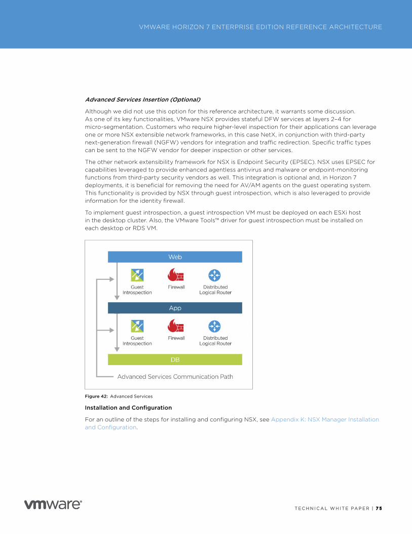
T E C H N I C A L W H I T E PA P E R | 7 5
VMWARE HORIZON 7 ENTERPRISE EDITION REFERENCE ARCHITECTURE
T E C H N I C A L W H I T E PA P E R | 7 5
Advanced Services Insertion (Optional)
Although we did not use this option for this reference architecture, it warrants some discussion . As one of its key functionalities, VMware NSX provides stateful DFW services at layers 2–4 for micro-segmentation . Customers who require higher-level inspection for their applications can leverage one or more NSX extensible network frameworks, in this case NetX, in conjunction with third-party next-generation firewall (NGFW) vendors for integration and traffic redirection . Specific traffic types can be sent to the NGFW vendor for deeper inspection or other services .
The other network extensibility framework for NSX is Endpoint Security (EPSEC) . NSX uses EPSEC for capabilities leveraged to provide enhanced agentless antivirus and malware or endpoint-monitoring functions from third-party security vendors as well . This integration is optional and, in Horizon 7 deployments, it is beneficial for removing the need for AV/AM agents on the guest operating system . This functionality is provided by NSX through guest introspection, which is also leveraged to provide information for the identity firewall .
To implement guest introspection, a guest introspection VM must be deployed on each ESXi host in the desktop cluster . Also, the VMware Tools™ driver for guest introspection must be installed on each desktop or RDS VM .
Figure 42: Advanced Services
Installation and Configuration
For an outline of the steps for installing and configuring NSX, see Appendix K: NSX Manager Installation and Configuration .
T E C H N I C A L W H I T E PA P E R | 7 6
VMWARE HORIZON 7 ENTERPRISE EDITION REFERENCE ARCHITECTURE
T E C H N I C A L W H I T E PA P E R | 7 6
Physical Environment DesignSeveral environment resources are required to support a Horizon 7 deployment . In most cases, the resources already exist . It is important to ensure that minimum versions are met and that any specific configurations for Horizon 7 are followed . For any external component that Horizon 7 depends on, the component must be designed to be scalable and highly available .
Active DirectoryHorizon 7 requires an Active Directory domain structure for user authentication and management . See the View Installation guide for details on the supported versions and preparation steps . Standard best practices for an Active Directory deployment should be followed to ensure that it is highly available .
Additionally, for Horizon 7, set up dedicated organizational units (OUs) for the machine accounts for virtual desktops and RDS hosts . Consider blocking inheritance on these OUs to stop any existing GPOs from having an undesired effect .
Group PolicyGroup Policy objects (GPOs) can be used in a variety of ways to control and configure both Horizon 7 components and standard Windows settings .
These policies are normally applied to the user or the computer Active Directory account, depending on where the objects are located in Active Directory . In a Horizon 7 environment, it is typical to set specific user policy settings for the specific Horizon 7 session only when a user connects to it . We also want to have user accounts processed separately from computer accounts with GPOs . This is where the loopback policy is widely used in any GPO that also needs to configure user settings . Enabling loopback processing is particularly important with User Environment Manager . User Environment Manager applies only user settings, so if the User Environment Manager GPOs are applied to computer objects, loopback processing must be enabled .
Refer to the Microsoft website for details .
DNSThe Domain Name System (DNS) is widely used in a Horizon 7 Enterprise Edition environment, from server components communication to clients and virtual desktops . Follow standard design principles for DNS, making it highly available . Additionally, ensure that:
• Forward and reverse zones are working well .
• Dynamic updates are enabled so that desktops register with DNS correctly .
• Scavenging is enabled and tuned to cope with the rapid cloning and replacement of desktops .
DHCPIn a Horizon 7 environment, desktops and RDS hosts rely on DHCP to get IP addressing information . DHCP must be allowed on the VM networks designated for these virtual desktops and RDS hosts .
The environment can be quite fluid, with instant-clone desktops being deleted at logout and recreated when a pool dips below the minimum number . Therefore, the DHCP lease period must be set to a relatively short period . The amount of time depends on the frequency of logouts and the lifetime of a clone .
Design Decision: DHCP must be available on the desktops and RDS hosts VM network . DHCP failover is implemented to ensure availability . The lease duration of the scopes used is set to 4 hours (based on an average logout after 8 hours) .
T E C H N I C A L W H I T E PA P E R | 7 7
VMWARE HORIZON 7 ENTERPRISE EDITION REFERENCE ARCHITECTURE
T E C H N I C A L W H I T E PA P E R | 7 7
Certificate AuthorityA Microsoft Enterprise Certificate Authority (CA) is a prerequisite for True SSO . A certificate template is created within the Microsoft CA and is used by True SSO to sign certificate signing requests (CSR) that are generated by the VM . These certificates are short-lived (approximately 1 hour) and are used solely for the purpose of single-signing a user into a desktop without the user having to provide AD credentials when accessing through VMware Identity Manager .
The Microsoft CA is used to create certificate-signing requests for Unified Access Gateway, VMware Identity Manager, and any other externally facing components . The CSR is then signed by a well-known external CA to ensure that any device connecting to the environment has access to a valid root certificate .
For details on setting up a Microsoft CA, see the View Administration guide .
Design Decision: A Microsoft Enterprise Certificate Authority was set up to support the True SSO capability .
Microsoft RDS LicensingHorizon 7 published applications use Microsoft RDSH servers as a shared server platform to host Windows applications . Microsoft RDS hosts require licensing through a Remote Desktop Licensing service . It is critical to ensure that the Remote Desktop Licensing service is highly available .
Key Management ServiceTo activate Windows (and Microsoft Office) licenses in a VDI environment, VMware recommends using Microsoft Key Management Service (KMS) with volume license keys . Because desktops are typically deleted at logout and are recreated frequently, it is important that this service be highly available . See the Microsoft documentation on how best to deploy volume activation .
Design Decision: Microsoft KMS was deployed in a highly available manner to allow desktops and RDS hosts to activate their Microsoft licenses .
DatabaseAs detailed in the component design section, several components require a database to store data and configurations . The database server needs to be highly available and scalable to match the demand . One option when using Microsoft SQL Server is to use clustering for HA .
Design Decision: Microsoft SQL Server was set up using Microsoft Failover Clustering to ensure availability .
More information is available in the Microsoft guides on SQL Server Failover Cluster Installation .
Load BalancerTo remove a single point of failure from some components, we can deploy more than one instance and use a third-party load balancer . This not only provides redundancy but also allows the load and processing to be spread across multiple instances of the component . To ensure that the load balancer itself does not become a point of failure, most load balancers allow for setup of multiple nodes in an HA or master-slave configuration .
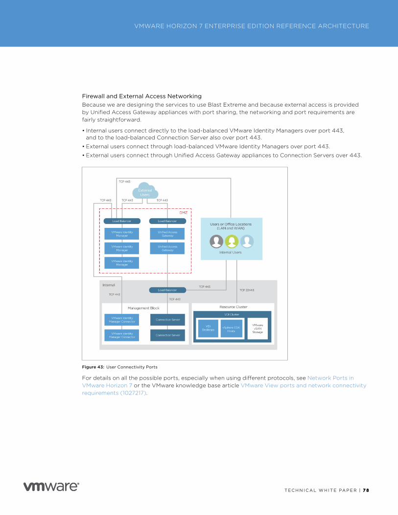
T E C H N I C A L W H I T E PA P E R | 7 8
VMWARE HORIZON 7 ENTERPRISE EDITION REFERENCE ARCHITECTURE
T E C H N I C A L W H I T E PA P E R | 7 8
Firewall and External Access NetworkingBecause we are designing the services to use Blast Extreme and because external access is provided by Unified Access Gateway appliances with port sharing, the networking and port requirements are fairly straightforward .
• Internal users connect directly to the load-balanced VMware Identity Managers over port 443, and to the load-balanced Connection Server also over port 443 .
• External users connect through load-balanced VMware Identity Managers over port 443 .
• External users connect through Unified Access Gateway appliances to Connection Servers over 443 .
Figure 43: User Connectivity Ports
For details on all the possible ports, especially when using different protocols, see Network Ports in VMware Horizon 7 or the VMware knowledge base article VMware View ports and network connectivity requirements (1027217) .

T E C H N I C A L W H I T E PA P E R | 7 9
VMWARE HORIZON 7 ENTERPRISE EDITION REFERENCE ARCHITECTURE
T E C H N I C A L W H I T E PA P E R | 7 9
File ServersUsers’ home drives, User Environment Manager repositories, and ThinApp shares are stored externally from the Horizon 7 environment on SMB shares provided by Windows file servers . We used two file servers with Distributed File Services enabled . This allows both servers to provide the SMB shares under a common shared namespace (DFS-N) .
We used DFS-R in a hub-spoke model to make sure that the primary file server replicates changes to the secondary file server . (Microsoft does not support multimaster replication of profile data .) In the event of an issue with one of the file servers, the share and data remain available . For more information, see DFS-R Overview from Microsoft .
Service Integration DesignAt this stage, we have our Horizon 7 Enterprise Edition components designed and deployed and have ensured that the environment has all the functionality and qualities that are required . We can now proceed to creating the parts from each component, and assembling and integrating them into the service that is delivered to end users .
Table 11 details the parts required for each service . The rest of this section details the design and build of each service .
BUSINESS PROCESS APPLICATION SERVICE
MOBILE SECURE WORKSPACE SERVICE
DEDICATED POWER WORKSPACE SERVICE
DEVELOPER WORKSPACE SERVICE
HIGH-PERFORMANCE WORKSPACE SERVICE
VMware Identity Manager
✓ ✓ ✓ ✓ ✓
Windows 10 instant clone
✓ ✓ ✓
RDSH instant clone
✓
Linux clone ✓
App Volumes AppStack
✓ ✓ ✓ ✓
App Volumes writable volume
✓ ✓
User Environment Manager
✓ ✓ ✓ ✓
Smart Policies ✓ ✓ ✓ ✓
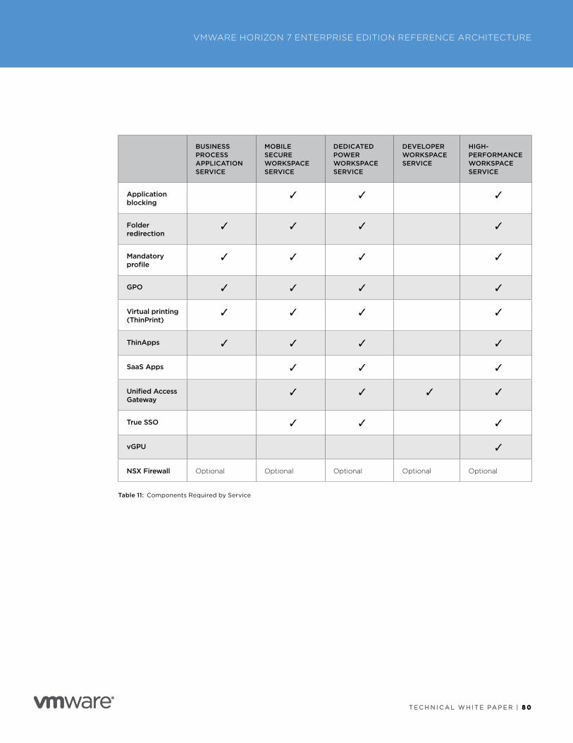
T E C H N I C A L W H I T E PA P E R | 8 0
VMWARE HORIZON 7 ENTERPRISE EDITION REFERENCE ARCHITECTURE
T E C H N I C A L W H I T E PA P E R | 8 0
BUSINESS PROCESS APPLICATION SERVICE
MOBILE SECURE WORKSPACE SERVICE
DEDICATED POWER WORKSPACE SERVICE
DEVELOPER WORKSPACE SERVICE
HIGH-PERFORMANCE WORKSPACE SERVICE
Application blocking
✓ ✓ ✓
Folder redirection
✓ ✓ ✓ ✓
Mandatory profile
✓ ✓ ✓ ✓
GPO ✓ ✓ ✓ ✓
Virtual printing (ThinPrint)
✓ ✓ ✓ ✓
ThinApps ✓ ✓ ✓ ✓
SaaS Apps ✓ ✓ ✓
Unified Access Gateway
✓ ✓ ✓ ✓
True SSO ✓ ✓ ✓
vGPU ✓
NSX Firewall Optional Optional Optional Optional Optional
Table 11: Components Required by Service
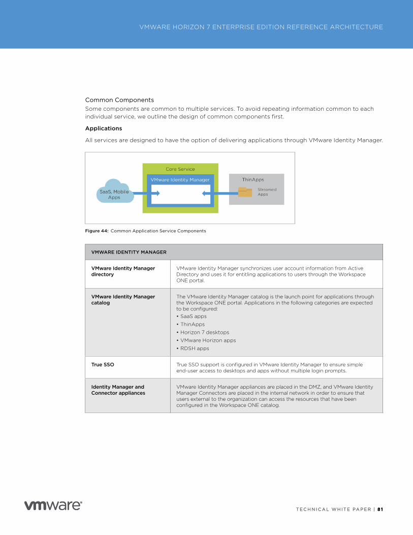
T E C H N I C A L W H I T E PA P E R | 8 1
VMWARE HORIZON 7 ENTERPRISE EDITION REFERENCE ARCHITECTURE
T E C H N I C A L W H I T E PA P E R | 8 1
Common ComponentsSome components are common to multiple services . To avoid repeating information common to each individual service, we outline the design of common components first .
Applications
All services are designed to have the option of delivering applications through VMware Identity Manager .
Figure 44: Common Application Service Components
VMWARE IDENTITY MANAGER
VMware Identity Manager directory
VMware Identity Manager synchronizes user account information from Active Directory and uses it for entitling applications to users through the Workspace ONE portal .
VMware Identity Manager catalog
The VMware Identity Manager catalog is the launch point for applications through the Workspace ONE portal . Applications in the following categories are expected to be configured:• SaaS apps
• ThinApps
• Horizon 7 desktops
• VMware Horizon apps
• RDSH apps
True SSO True SSO support is configured in VMware Identity Manager to ensure simple end-user access to desktops and apps without multiple login prompts .
Identity Manager and Connector appliances
VMware Identity Manager appliances are placed in the DMZ, and VMware Identity Manager Connectors are placed in the internal network in order to ensure that users external to the organization can access the resources that have been configured in the Workspace ONE catalog .
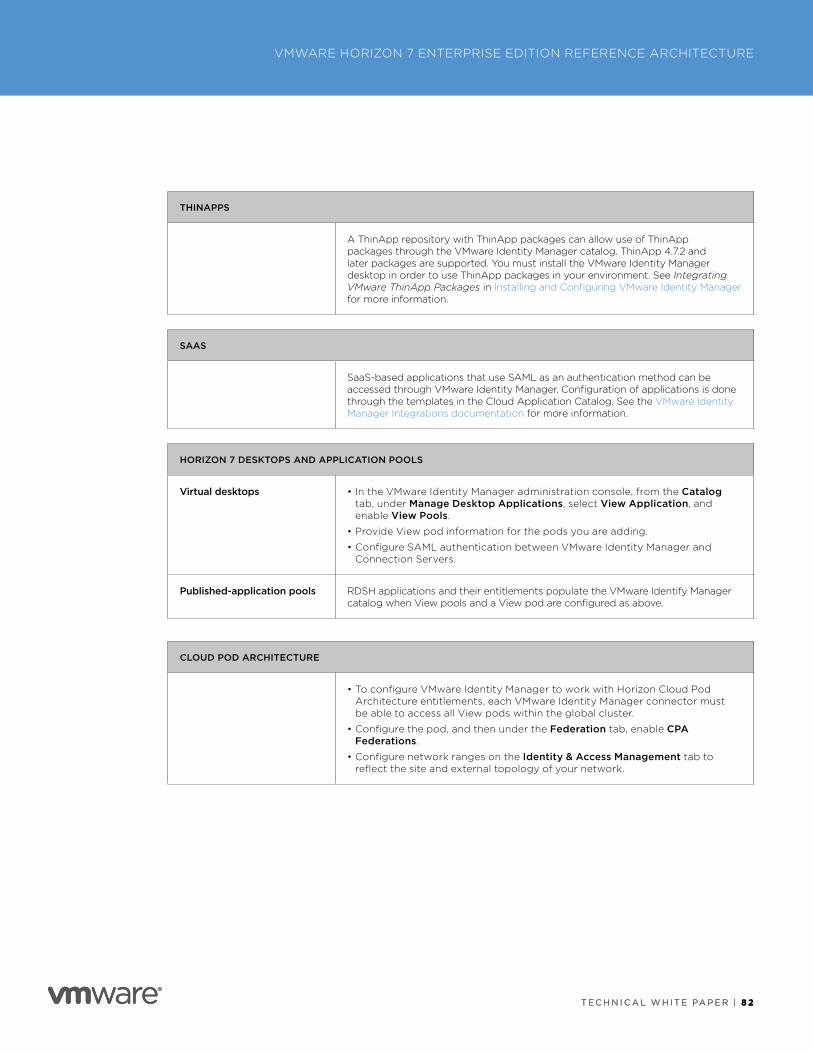
T E C H N I C A L W H I T E PA P E R | 8 2
VMWARE HORIZON 7 ENTERPRISE EDITION REFERENCE ARCHITECTURE
T E C H N I C A L W H I T E PA P E R | 8 2
THINAPPS
A ThinApp repository with ThinApp packages can allow use of ThinApp packages through the VMware Identity Manager catalog . ThinApp 4 .7 .2 and later packages are supported . You must install the VMware Identity Manager desktop in order to use ThinApp packages in your environment . See Integrating VMware ThinApp Packages in Installing and Configuring VMware Identity Manager for more information .
SAAS
SaaS-based applications that use SAML as an authentication method can be accessed through VMware Identity Manager . Configuration of applications is done through the templates in the Cloud Application Catalog . See the VMware Identity Manager Integrations documentation for more information .
HORIZON 7 DESKTOPS AND APPLICATION POOLS
Virtual desktops • In the VMware Identity Manager administration console, from the Catalog tab, under Manage Desktop Applications, select View Application, and enable View Pools .
• Provide View pod information for the pods you are adding .
• Configure SAML authentication between VMware Identity Manager and Connection Servers .
Published-application pools RDSH applications and their entitlements populate the VMware Identify Manager catalog when View pools and a View pod are configured as above .
CLOUD POD ARCHITECTURE
• To configure VMware Identity Manager to work with Horizon Cloud Pod Architecture entitlements, each VMware Identity Manager connector must be able to access all View pods within the global cluster .
• Configure the pod, and then under the Federation tab, enable CPA Federations .
• Configure network ranges on the Identity & Access Management tab to reflect the site and external topology of your network .
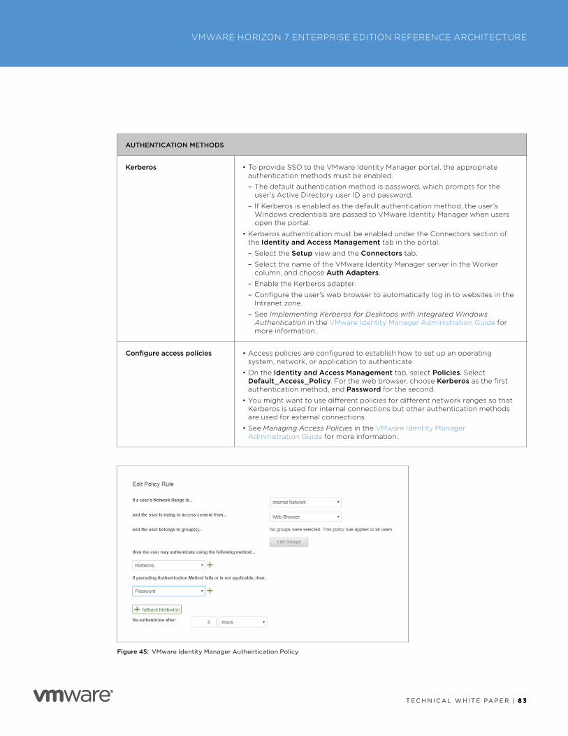
T E C H N I C A L W H I T E PA P E R | 8 3
VMWARE HORIZON 7 ENTERPRISE EDITION REFERENCE ARCHITECTURE
T E C H N I C A L W H I T E PA P E R | 8 3
AUTHENTICATION METHODS
Kerberos • To provide SSO to the VMware Identity Manager portal, the appropriate authentication methods must be enabled .
– The default authentication method is password, which prompts for the user’s Active Directory user ID and password .
– If Kerberos is enabled as the default authentication method, the user’s Windows credentials are passed to VMware Identity Manager when users open the portal .
• Kerberos authentication must be enabled under the Connectors section of the Identity and Access Management tab in the portal .
– Select the Setup view and the Connectors tab .
– Select the name of the VMware Identity Manager server in the Worker column, and choose Auth Adapters .
– Enable the Kerberos adapter .
– Configure the user’s web browser to automatically log in to websites in the Intranet zone .
– See Implementing Kerberos for Desktops with Integrated Windows Authentication in the VMware Identity Manager Administration Guide for more information .
Configure access policies • Access policies are configured to establish how to set up an operating system, network, or application to authenticate .
• On the Identity and Access Management tab, select Policies . Select Default_Access_Policy . For the web browser, choose Kerberos as the first authentication method, and Password for the second .
• You might want to use different policies for different network ranges so that Kerberos is used for internal connections but other authentication methods are used for external connections .
• See Managing Access Policies in the VMware Identity Manager Administration Guide for more information .
Figure 45: VMware Identity Manager Authentication Policy
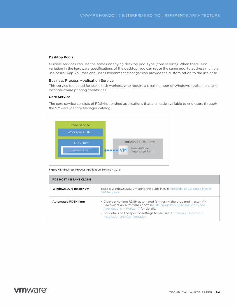
T E C H N I C A L W H I T E PA P E R | 8 4
VMWARE HORIZON 7 ENTERPRISE EDITION REFERENCE ARCHITECTURE
T E C H N I C A L W H I T E PA P E R | 8 4
Desktop Pools
Multiple services can use the same underlying desktop pool type (core service) . When there is no variation in the hardware specifications of the desktop, you can reuse the same pool to address multiple use cases . App Volumes and User Environment Manager can provide the customization to the use case .
Business Process Application ServiceThis service is created for static task workers, who require a small number of Windows applications and location-aware printing capabilities .
Core Service
The core service consists of RDSH-published applications that are made available to end users through the VMware Identity Manager catalog .
Figure 46: Business Process Application Service – Core
RDS HOST INSTANT CLONE
Windows 2016 master VM Build a Windows 2016 VM using the guidelines in Appendix E: Building a Master VM Template .
Automated RDSH farm • Create a Horizon RDSH automated farm using the prepared master VM . See Create an Automated Farm in Setting Up Published Desktops and Applications in Horizon 7 for details .
• For details on the specific settings to use, see Appendix C: Horizon 7 Installation and Configuration .
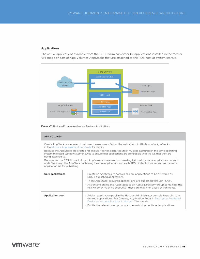
T E C H N I C A L W H I T E PA P E R | 8 5
VMWARE HORIZON 7 ENTERPRISE EDITION REFERENCE ARCHITECTURE
T E C H N I C A L W H I T E PA P E R | 8 5
Applications
The actual applications available from the RDSH farm can either be applications installed in the master VM image or part of App Volumes AppStacks that are attached to the RDS host at system startup .
Figure 47: Business Process Application Service – Applications
APP VOLUMES
Create AppStacks as required to address the use cases . Follow the instructions in Working with AppStacks in the VMware App Volumes User Guide for details . Because the AppStacks are created for an RDSH server, each AppStack must be captured on the same operating system (we used Windows Server 2016) to ensure that applications are compatible with the OS that they are being attached to .Because we use RDSH instant clones, App Volumes saves us from needing to install the same applications on each node . We assign the AppStack containing the core applications and each RDSH instant-clone server has the same application set for publishing .
Core applications • Create an AppStack to contain all core applications to be delivered as RDSH-published applications .
• These AppStack-delivered applications are published through RDSH .
• Assign and entitle the AppStacks to an Active Directory group containing the RDSH server machine accounts—these are machine-based assignments .
Application pool • Add an application pool in the Horizon Administrator console to publish the desired applications . See Creating Application Pools in Setting Up Published Desktops and Applications in Horizon 7 for details .
• Entitle the relevant user groups to the matching published applications .
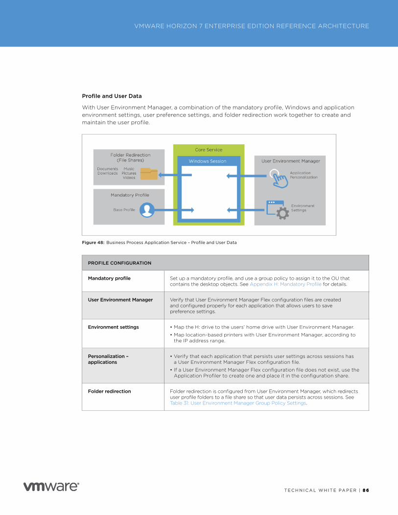
T E C H N I C A L W H I T E PA P E R | 8 6
VMWARE HORIZON 7 ENTERPRISE EDITION REFERENCE ARCHITECTURE
T E C H N I C A L W H I T E PA P E R | 8 6
Profile and User Data
With User Environment Manager, a combination of the mandatory profile, Windows and application environment settings, user preference settings, and folder redirection work together to create and maintain the user profile .
Figure 48: Business Process Application Service – Profile and User Data
PROFILE CONFIGURATION
Mandatory profile Set up a mandatory profile, and use a group policy to assign it to the OU that contains the desktop objects . See Appendix H: Mandatory Profile for details .
User Environment Manager Verify that User Environment Manager Flex configuration files are created and configured properly for each application that allows users to save preference settings .
Environment settings • Map the H: drive to the users’ home drive with User Environment Manager .
• Map location-based printers with User Environment Manager, according to the IP address range .
Personalization – applications
• Verify that each application that persists user settings across sessions has a User Environment Manager Flex configuration file .
• If a User Environment Manager Flex configuration file does not exist, use the Application Profiler to create one and place it in the configuration share .
Folder redirection Folder redirection is configured from User Environment Manager, which redirects user profile folders to a file share so that user data persists across sessions . See Table 31: User Environment Manager Group Policy Settings .
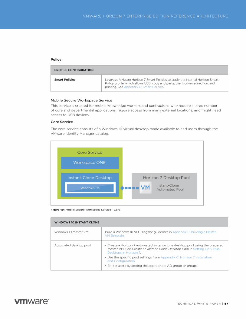
T E C H N I C A L W H I T E PA P E R | 8 7
VMWARE HORIZON 7 ENTERPRISE EDITION REFERENCE ARCHITECTURE
T E C H N I C A L W H I T E PA P E R | 8 7
Policy
PROFILE CONFIGURATION
Smart Policies Leverage VMware Horizon 7 Smart Policies to apply the Internal Horizon Smart Policy profile, which allows USB, copy and paste, client drive redirection, and printing . See Appendix G: Smart Policies .
Mobile Secure Workspace ServiceThis service is created for mobile knowledge workers and contractors, who require a large number of core and departmental applications, require access from many external locations, and might need access to USB devices .
Core Service
The core service consists of a Windows 10 virtual desktop made available to end users through the VMware Identity Manager catalog .
Figure 49: Mobile Secure Workspace Service – Core
WINDOWS 10 INSTANT CLONE
Windows 10 master VM Build a Windows 10 VM using the guidelines in Appendix E: Building a Master VM Template .
Automated desktop pool • Create a Horizon 7 automated instant-clone desktop pool using the prepared master VM . See Create an Instant-Clone Desktop Pool in Setting Up Virtual Desktops in Horizon 7 .
• Use the specific pool settings from Appendix C: Horizon 7 Installation and Configuration .
• Entitle users by adding the appropriate AD group or groups .
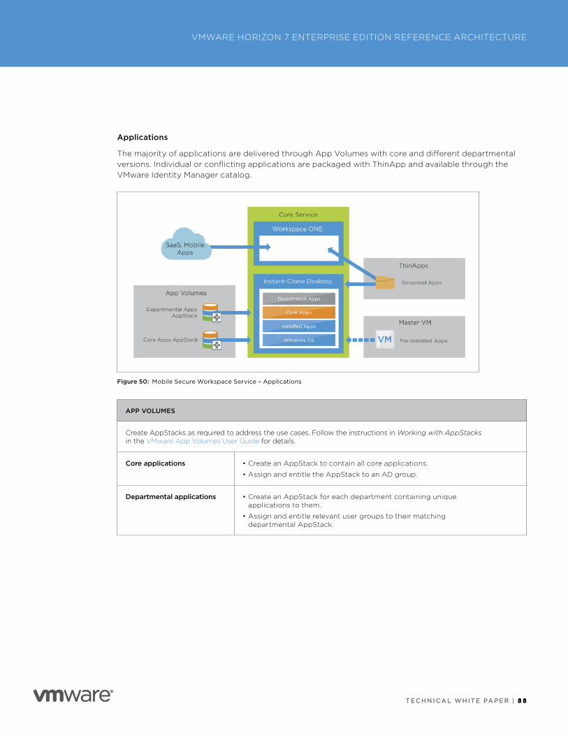
T E C H N I C A L W H I T E PA P E R | 8 8
VMWARE HORIZON 7 ENTERPRISE EDITION REFERENCE ARCHITECTURE
T E C H N I C A L W H I T E PA P E R | 8 8
Applications
The majority of applications are delivered through App Volumes with core and different departmental versions . Individual or conflicting applications are packaged with ThinApp and available through the VMware Identity Manager catalog .
Figure 50: Mobile Secure Workspace Service – Applications
APP VOLUMES
Create AppStacks as required to address the use cases . Follow the instructions in Working with AppStacks in the VMware App Volumes User Guide for details .
Core applications • Create an AppStack to contain all core applications .
• Assign and entitle the AppStack to an AD group .
Departmental applications • Create an AppStack for each department containing unique applications to them .
• Assign and entitle relevant user groups to their matching departmental AppStack .
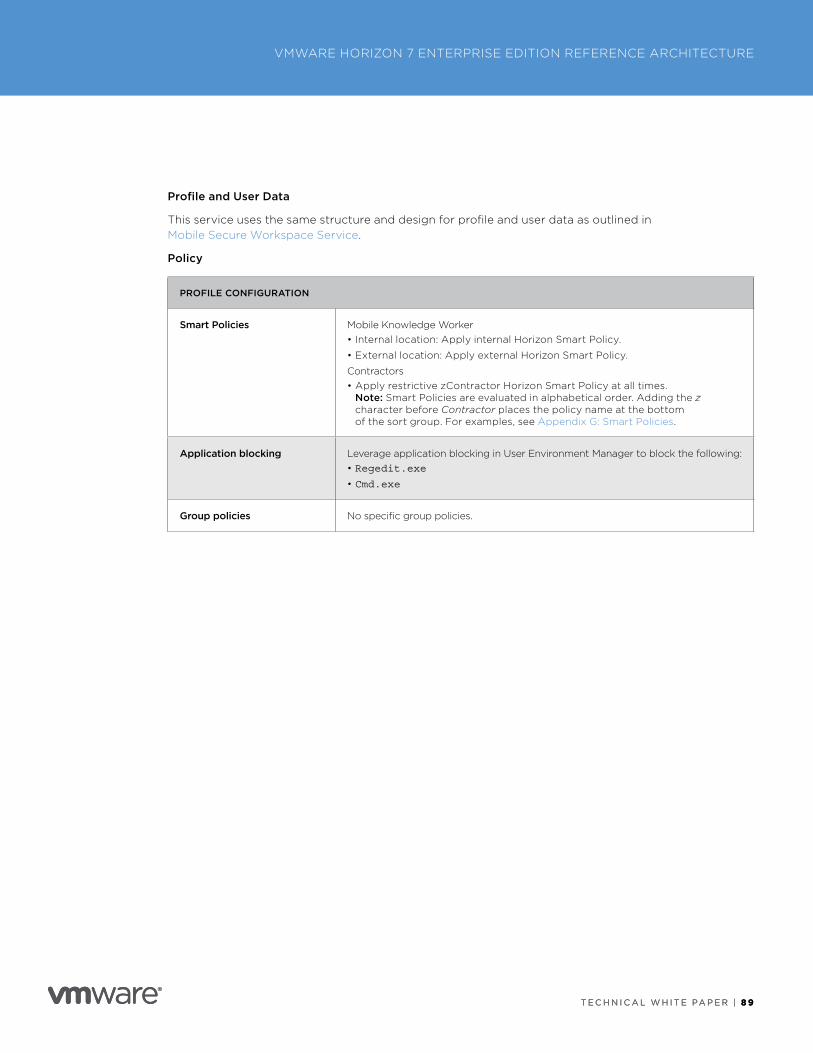
T E C H N I C A L W H I T E PA P E R | 8 9
VMWARE HORIZON 7 ENTERPRISE EDITION REFERENCE ARCHITECTURE
T E C H N I C A L W H I T E PA P E R | 8 9
Profile and User Data
This service uses the same structure and design for profile and user data as outlined in Mobile Secure Workspace Service .
Policy
PROFILE CONFIGURATION
Smart Policies Mobile Knowledge Worker • Internal location: Apply internal Horizon Smart Policy .
• External location: Apply external Horizon Smart Policy .
Contractors• Apply restrictive zContractor Horizon Smart Policy at all times .
Note: Smart Policies are evaluated in alphabetical order . Adding the z character before Contractor places the policy name at the bottom of the sort group . For examples, see Appendix G: Smart Policies .
Application blocking Leverage application blocking in User Environment Manager to block the following:• Regedit.exe
• Cmd.exe
Group policies No specific group policies .
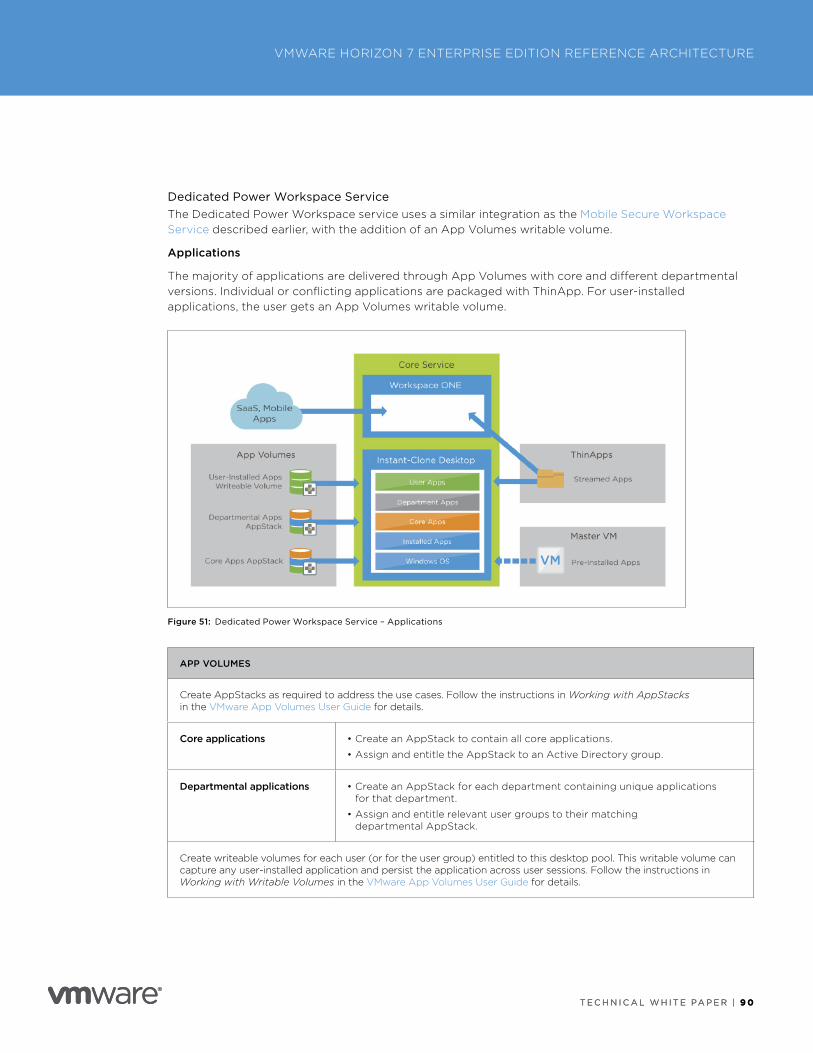
T E C H N I C A L W H I T E PA P E R | 9 0
VMWARE HORIZON 7 ENTERPRISE EDITION REFERENCE ARCHITECTURE
T E C H N I C A L W H I T E PA P E R | 9 0
Dedicated Power Workspace ServiceThe Dedicated Power Workspace service uses a similar integration as the Mobile Secure Workspace Service described earlier, with the addition of an App Volumes writable volume .
Applications
The majority of applications are delivered through App Volumes with core and different departmental versions . Individual or conflicting applications are packaged with ThinApp . For user-installed applications, the user gets an App Volumes writable volume .
Figure 51: Dedicated Power Workspace Service – Applications
APP VOLUMES
Create AppStacks as required to address the use cases . Follow the instructions in Working with AppStacks in the VMware App Volumes User Guide for details .
Core applications • Create an AppStack to contain all core applications .
• Assign and entitle the AppStack to an Active Directory group .
Departmental applications • Create an AppStack for each department containing unique applications for that department .
• Assign and entitle relevant user groups to their matching departmental AppStack .
Create writeable volumes for each user (or for the user group) entitled to this desktop pool . This writable volume can capture any user-installed application and persist the application across user sessions . Follow the instructions in Working with Writable Volumes in the VMware App Volumes User Guide for details .
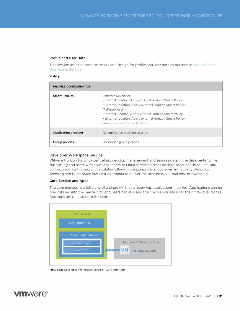
T E C H N I C A L W H I T E PA P E R | 9 1
VMWARE HORIZON 7 ENTERPRISE EDITION REFERENCE ARCHITECTURE
T E C H N I C A L W H I T E PA P E R | 9 1
Profile and User Data
This service uses the same structure and design for profile and user data as outlined in Mobile Secure Workspace Service .
Policy
PROFILE CONFIGURATION
Smart Policies Software Developer • Internal location: Apply internal Horizon Smart Policy .
• External location: Apply external Horizon Smart Policy .
IT (Power User) • Internal location: Apply internal Horizon Smart Policy .
• External location: Apply external Horizon Smart Policy .
See Appendix G: Smart Policies .
Application blocking No application blocking settings .
Group policies No specific group policies .
Developer Workspace ServiceVMware Horizon for Linux centralizes desktop management and secures data in the data center while supporting end users with seamless access to Linux services across devices, locations, mediums, and connections . Furthermore, this solution allows organizations to move away from costly Windows licensing and to embrace low-cost endpoints to deliver the best possible total cost of ownership .
Core Service and Apps
The core desktop is a full clone of a Linux VM that already has applications installed . Applications can be pre-installed into the master VM, and users can also add their own applications to their individual clones . Desktops are persistent to the user .
Figure 52: Developer Workspace Service – Core and Apps
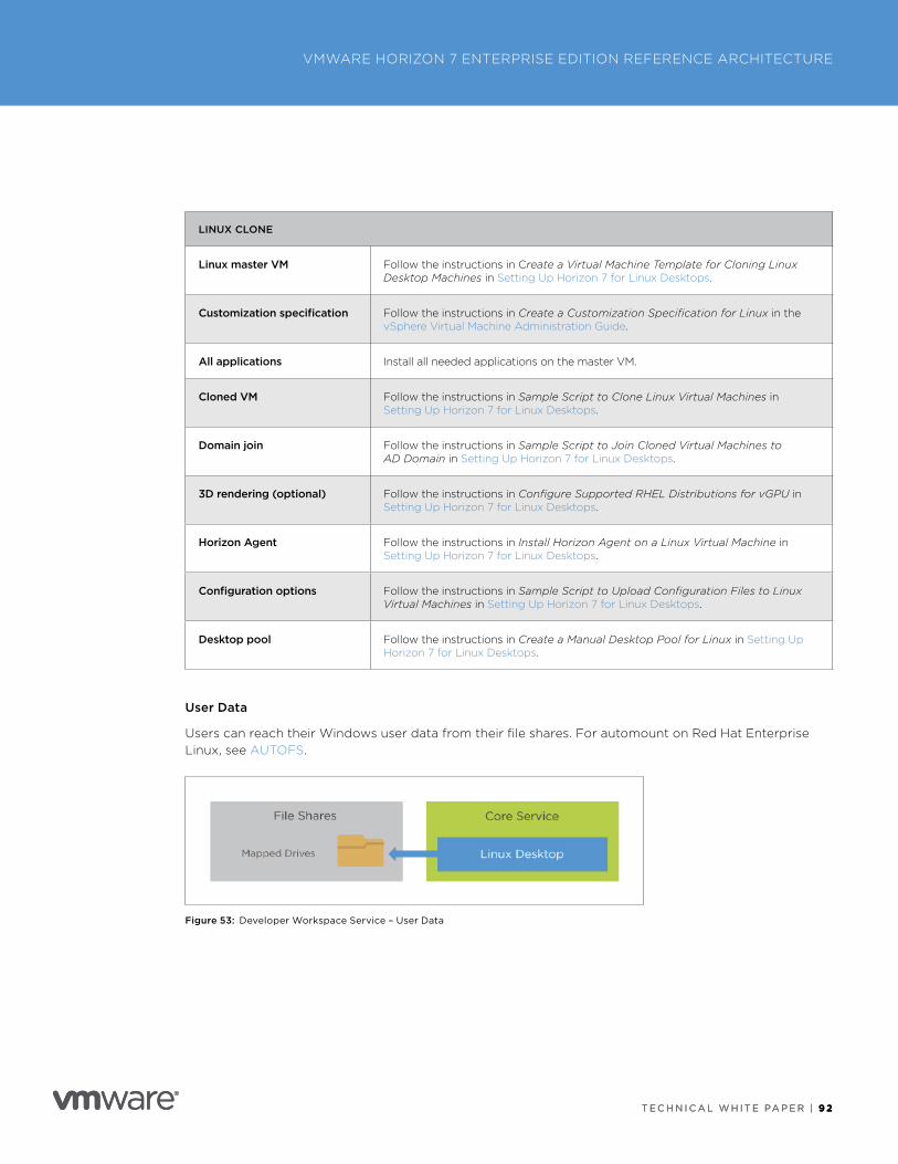
T E C H N I C A L W H I T E PA P E R | 9 2
VMWARE HORIZON 7 ENTERPRISE EDITION REFERENCE ARCHITECTURE
T E C H N I C A L W H I T E PA P E R | 9 2
LINUX CLONE
Linux master VM Follow the instructions in Create a Virtual Machine Template for Cloning Linux Desktop Machines in Setting Up Horizon 7 for Linux Desktops .
Customization specification Follow the instructions in Create a Customization Specification for Linux in the vSphere Virtual Machine Administration Guide .
All applications Install all needed applications on the master VM .
Cloned VM Follow the instructions in Sample Script to Clone Linux Virtual Machines in Setting Up Horizon 7 for Linux Desktops .
Domain join Follow the instructions in Sample Script to Join Cloned Virtual Machines to AD Domain in Setting Up Horizon 7 for Linux Desktops .
3D rendering (optional) Follow the instructions in Configure Supported RHEL Distributions for vGPU in Setting Up Horizon 7 for Linux Desktops .
Horizon Agent Follow the instructions in Install Horizon Agent on a Linux Virtual Machine in Setting Up Horizon 7 for Linux Desktops .
Configuration options Follow the instructions in Sample Script to Upload Configuration Files to Linux Virtual Machines in Setting Up Horizon 7 for Linux Desktops .
Desktop pool Follow the instructions in Create a Manual Desktop Pool for Linux in Setting Up Horizon 7 for Linux Desktops .
User Data
Users can reach their Windows user data from their file shares . For automount on Red Hat Enterprise Linux, see AUTOFS .
Figure 53: Developer Workspace Service – User Data
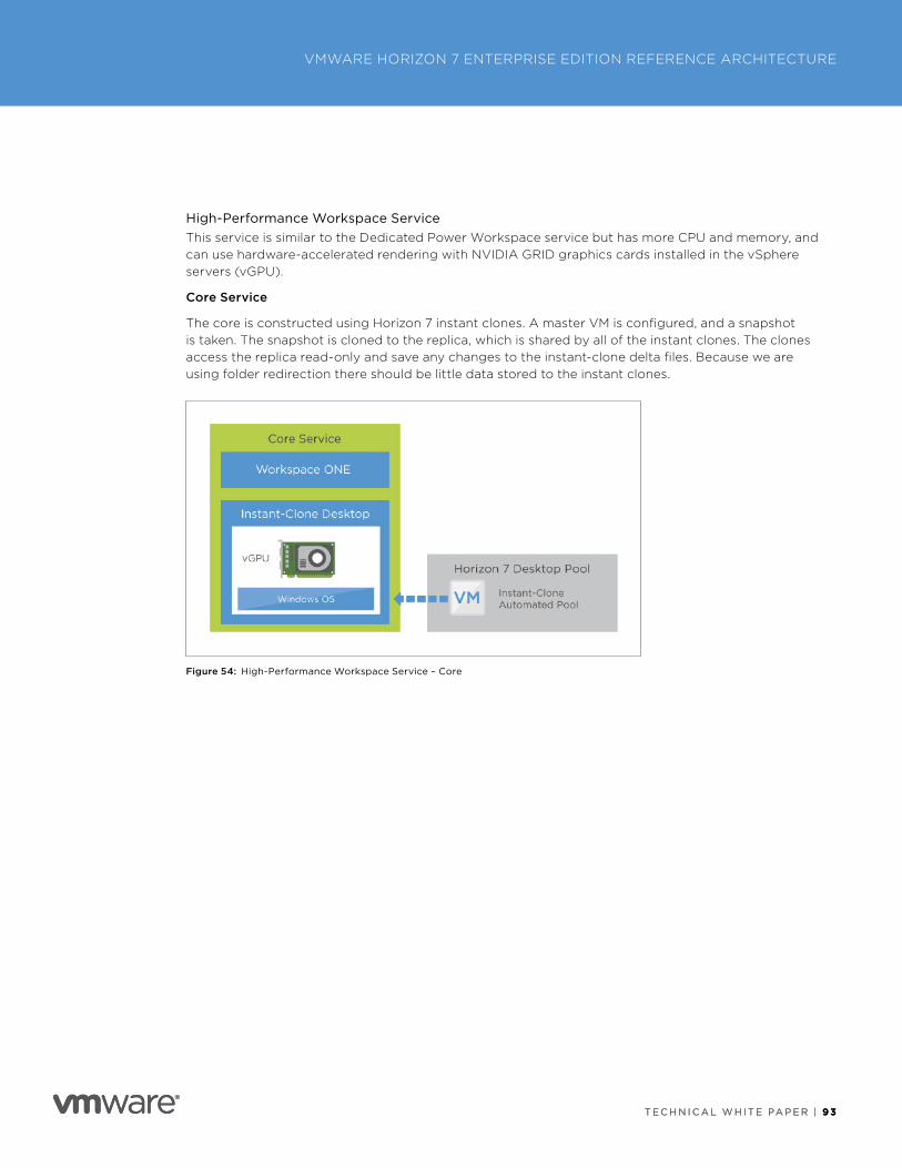
T E C H N I C A L W H I T E PA P E R | 9 3
VMWARE HORIZON 7 ENTERPRISE EDITION REFERENCE ARCHITECTURE
T E C H N I C A L W H I T E PA P E R | 9 3
High-Performance Workspace ServiceThis service is similar to the Dedicated Power Workspace service but has more CPU and memory, and can use hardware-accelerated rendering with NVIDIA GRID graphics cards installed in the vSphere servers (vGPU) .
Core Service
The core is constructed using Horizon 7 instant clones . A master VM is configured, and a snapshot is taken . The snapshot is cloned to the replica, which is shared by all of the instant clones . The clones access the replica read-only and save any changes to the instant-clone delta files . Because we are using folder redirection there should be little data stored to the instant clones .
Figure 54: High-Performance Workspace Service – Core
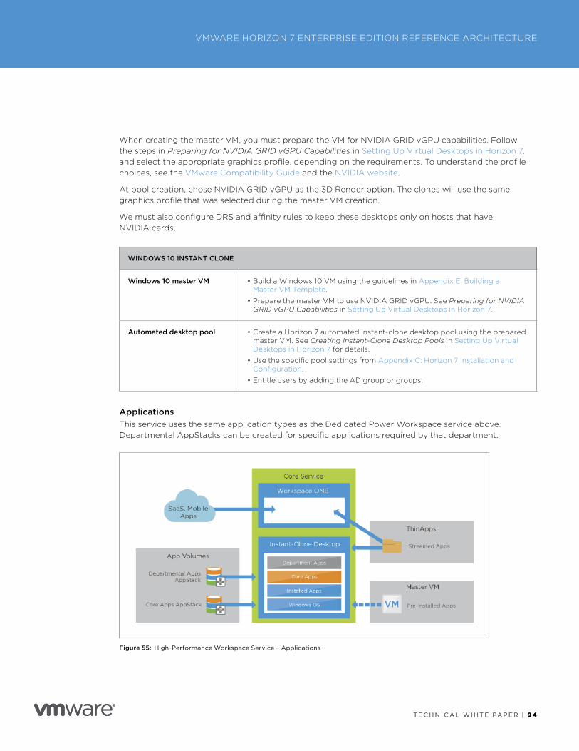
T E C H N I C A L W H I T E PA P E R | 9 4
VMWARE HORIZON 7 ENTERPRISE EDITION REFERENCE ARCHITECTURE
T E C H N I C A L W H I T E PA P E R | 9 4
When creating the master VM, you must prepare the VM for NVIDIA GRID vGPU capabilities . Follow the steps in Preparing for NVIDIA GRID vGPU Capabilities in Setting Up Virtual Desktops in Horizon 7, and select the appropriate graphics profile, depending on the requirements . To understand the profile choices, see the VMware Compatibility Guide and the NVIDIA website .
At pool creation, chose NVIDIA GRID vGPU as the 3D Render option . The clones will use the same graphics profile that was selected during the master VM creation .
We must also configure DRS and affinity rules to keep these desktops only on hosts that have NVIDIA cards .
WINDOWS 10 INSTANT CLONE
Windows 10 master VM • Build a Windows 10 VM using the guidelines in Appendix E: Building a Master VM Template .
• Prepare the master VM to use NVIDIA GRID vGPU . See Preparing for NVIDIA GRID vGPU Capabilities in Setting Up Virtual Desktops in Horizon 7 .
Automated desktop pool • Create a Horizon 7 automated instant-clone desktop pool using the prepared master VM . See Creating Instant-Clone Desktop Pools in Setting Up Virtual Desktops in Horizon 7 for details .
• Use the specific pool settings from Appendix C: Horizon 7 Installation and Configuration .
• Entitle users by adding the AD group or groups .
ApplicationsThis service uses the same application types as the Dedicated Power Workspace service above . Departmental AppStacks can be created for specific applications required by that department .
Figure 55: High-Performance Workspace Service – Applications
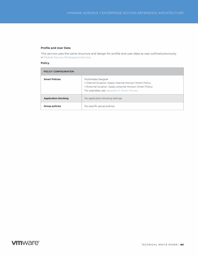
T E C H N I C A L W H I T E PA P E R | 9 5
VMWARE HORIZON 7 ENTERPRISE EDITION REFERENCE ARCHITECTURE
T E C H N I C A L W H I T E PA P E R | 9 5
Profile and User Data
This service uses the same structure and design for profile and user data as was outlined previously in Mobile Secure Workspace Service .
Policy
POLICY CONFIGURATION
Smart Policies Multimedia Designer • Internal location: Apply internal Horizon Smart Policy .
• External location: Apply external Horizon Smart Policy .
For examples, see Appendix G: Smart Policies .
Application blocking No application blocking settings .
Group policies No specific group policies .
T E C H N I C A L W H I T E PA P E R | 9 6
VMWARE HORIZON 7 ENTERPRISE EDITION REFERENCE ARCHITECTURE
T E C H N I C A L W H I T E PA P E R | 9 6
User Experience DesignThe success of any end-user computing solution hinges on the quality of the end user’s experience . This can sometimes be difficult to measure because it can be affected by the user’s perception . It is important to understand how users will interact with the environment and whether it delivers what they need . Feedback from users should be incorporated into the design—and on an ongoing basis—to ensure that any required changes are made to keep the solution relevant .
• How do users connect?
• How do users interact with the interfaces, applications, and other aspects of the solution?
• Does the workflow address the way users need to work?
• What does the typical workflow look like for them?
• Do the client device capabilities fulfill the use case needs?
• Does the environment deliver a usable and reliable experience? Consider response time, availability, ease of use, and the ability to customize to individual needs .
Client Devices (Endpoints)One of the aims of Horizon 7 Enterprise Edition is to allow access to applications and desktops from any device . Using VMware Identity Manager as the common access mechanism for all resources provides a familiar interface and experience across all devices .
When accessing virtual desktops and RDSH-published applications, it should be noted that not all clients are equal, and all clients do not have the same capabilities . An iPad might be great for mobility and certain use cases, but might not be suitable if features such as multiple monitors and USB redirection are required .
A user’s main working client device should match the requirements for that use case . This does not mean that a user is limited to just that device . It just means that other devices might not have all the functionality needed to deliver the full experience and capabilities .
• Understand the use cases thoroughly .
• There is no one perfect endpoint—different uses require different choices .
• Users will use multiple devices—try to set expectations about differences .
• Understand Microsoft Virtual Desktop Access (VDA) licensing implications .
One area that needs careful consideration is the use of Real-Time Audio-Video (RTAV) solutions such as Microsoft Skype for Business (Lync), especially where this includes VoIP or video calls . See Configuring Real-Time Audio-Video in Configuring Remote Desktop Features in Horizon 7 and in Microsoft Lync 2013 and Skype for Business on VMware Horizon 7 .
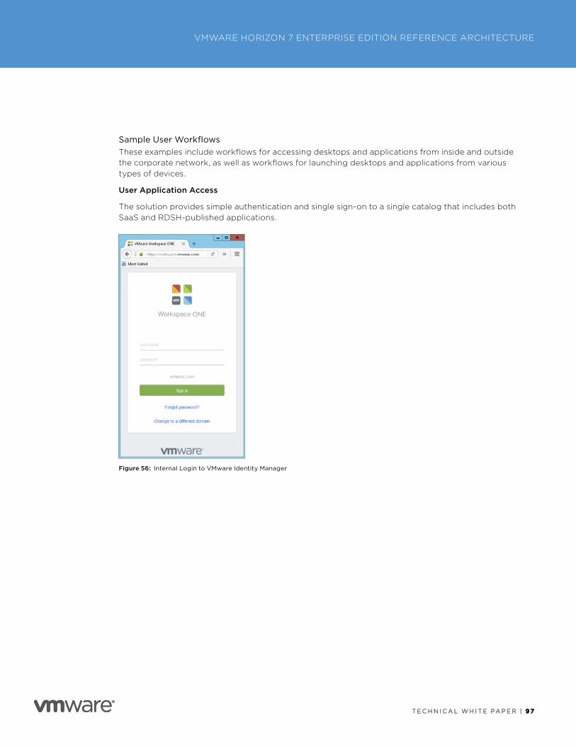
T E C H N I C A L W H I T E PA P E R | 9 7
VMWARE HORIZON 7 ENTERPRISE EDITION REFERENCE ARCHITECTURE
T E C H N I C A L W H I T E PA P E R | 9 7
Sample User WorkflowsThese examples include workflows for accessing desktops and applications from inside and outside the corporate network, as well as workflows for launching desktops and applications from various types of devices .
User Application Access
The solution provides simple authentication and single sign-on to a single catalog that includes both SaaS and RDSH-published applications .
Figure 56: Internal Login to VMware Identity Manager
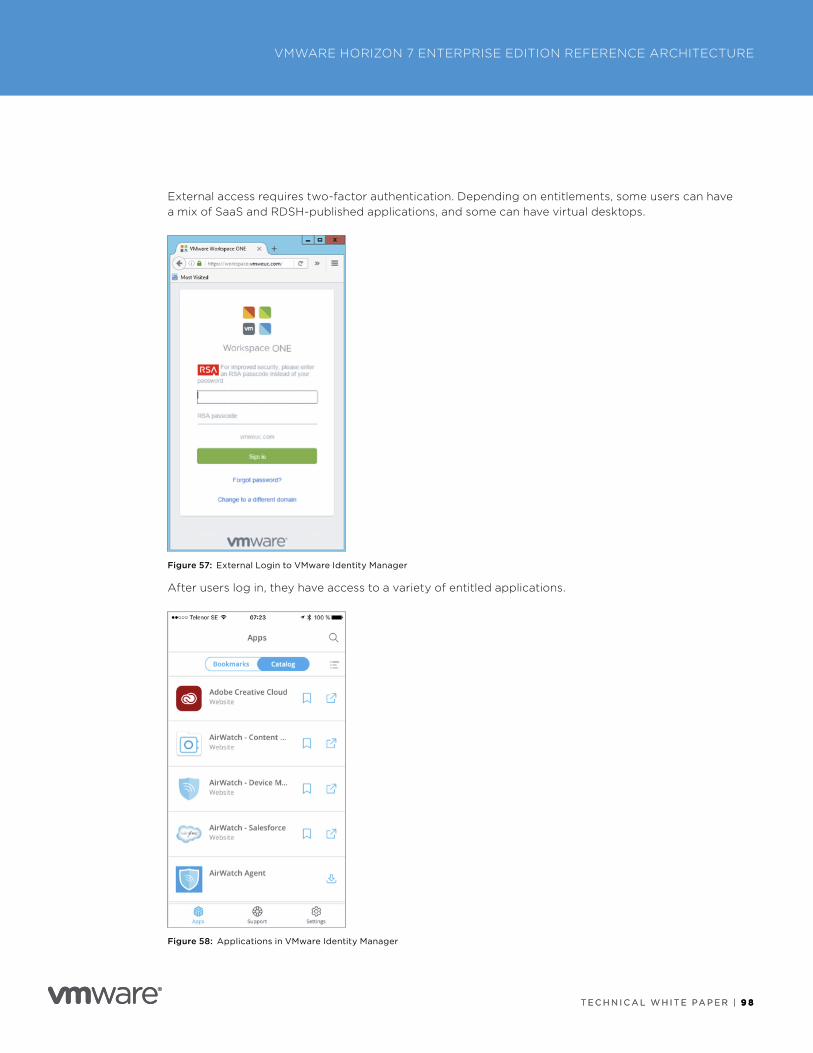
T E C H N I C A L W H I T E PA P E R | 9 8
VMWARE HORIZON 7 ENTERPRISE EDITION REFERENCE ARCHITECTURE
T E C H N I C A L W H I T E PA P E R | 9 8
External access requires two-factor authentication . Depending on entitlements, some users can have a mix of SaaS and RDSH-published applications, and some can have virtual desktops .
Figure 57: External Login to VMware Identity Manager
After users log in, they have access to a variety of entitled applications .
Figure 58: Applications in VMware Identity Manager
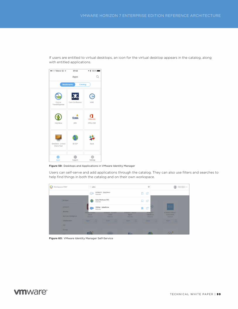
T E C H N I C A L W H I T E PA P E R | 9 9
VMWARE HORIZON 7 ENTERPRISE EDITION REFERENCE ARCHITECTURE
T E C H N I C A L W H I T E PA P E R | 9 9
If users are entitled to virtual desktops, an icon for the virtual desktop appears in the catalog, along with entitled applications .
Figure 59: Desktops and Applications in VMware Identity Manager
Users can self-serve and add applications through the catalog . They can also use filters and searches to help find things in both the catalog and on their own workspace .
Figure 60: VMware Identity Manager Self-Service
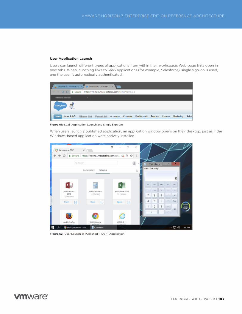
T E C H N I C A L W H I T E PA P E R | 1 0 0
VMWARE HORIZON 7 ENTERPRISE EDITION REFERENCE ARCHITECTURE
T E C H N I C A L W H I T E PA P E R | 1 0 0
User Application Launch
Users can launch different types of applications from within their workspace . Web page links open in new tabs . When launching links to SaaS applications (for example, Salesforce), single sign-on is used, and the user is automatically authenticated .
Figure 61: SaaS Application Launch and Single Sign-On
When users launch a published application, an application window opens on their desktop, just as if the Windows-based application were natively installed .
Figure 62: User Launch of Published (RDSH) Application
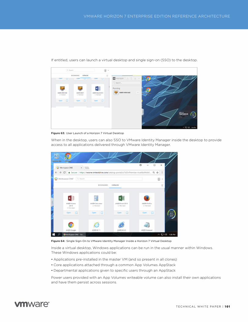
T E C H N I C A L W H I T E PA P E R | 1 0 1
VMWARE HORIZON 7 ENTERPRISE EDITION REFERENCE ARCHITECTURE
T E C H N I C A L W H I T E PA P E R | 1 0 1
If entitled, users can launch a virtual desktop and single sign-on (SSO) to the desktop .
Figure 63: User Launch of a Horizon 7 Virtual Desktop
When in the desktop, users can also SSO to VMware Identity Manager inside the desktop to provide access to all applications delivered through VMware Identity Manager .
Figure 64: Single Sign-On to VMware Identity Manager Inside a Horizon 7 Virtual Desktop
Inside a virtual desktop, Windows applications can be run in the usual manner within Windows . These Windows applications could be:
• Applications pre-installed in the master VM (and so present in all clones)
• Core applications attached through a common App Volumes AppStack
• Departmental applications given to specific users through an AppStack
Power users provided with an App Volumes writeable volume can also install their own applications and have them persist across sessions .
T E C H N I C A L W H I T E PA P E R | 1 0 2
VMWARE HORIZON 7 ENTERPRISE EDITION REFERENCE ARCHITECTURE
T E C H N I C A L W H I T E PA P E R | 1 0 2
Appendix A: Use Case DefinitionsEach use case defines what tasks a particular user, who plays a particular role, will be doing in the Horizon 7 solution . This reference architecture includes the following use cases:
• Static Task Worker
• Mobile Knowledge Worker
• Software Developer/IT (Power User)
• Multimedia Designer
• Contractor
Static Task WorkerStatic task workers are typically fixed to a specific location with no remote access requirement . Examples include call center worker, administration worker, and retail user . A static task worker:
• Uses a small number of Microsoft Windows applications . They do not install their own applications and do not require SaaS application access .
• Requires location-aware printing .
Mobile Knowledge WorkerA mobile knowledge worker could be a hospital clinician, a company employee, or someone who works in finance or marketing . This is a catch-all use case for many corporate use cases . A mobile knowledge worker:
• Mainly uses applications from a corporate location, but might access applications from mobile locations .
• Uses a large number of core and departmental applications but does not install their own applications . Requires SaaS application access .
• Has a video playback and Flash content requirement . Their GPU requirement is minimal, but GPU would improve user experience .
• Requires access to USB devices .
• Requires location-aware printing .
• Requires two-factor authentication when accessing applications remotely .
Software Developer/IT (Power User)Power users require administration rights to install applications . They could be using either a Windows or a Linux OS, with many applications, some of which require extensive CPU and memory resources . A power user:
• Mainly uses applications from a corporate location, but might access applications from mobile locations .
• Uses a large number of core and departmental applications and installs their own applications . Requires SaaS application access .
• Has a video playback and Flash content requirement .
• Requires two-factor authentication when accessing applications remotely .
T E C H N I C A L W H I T E PA P E R | 1 0 3
VMWARE HORIZON 7 ENTERPRISE EDITION REFERENCE ARCHITECTURE
T E C H N I C A L W H I T E PA P E R | 1 0 3
Multimedia DesignerMultimedia designers are intensive users that require GPU-accelerated applications, intensive CPU and memory workloads, or both . Examples are CAD and CAM designers, architects, video editors and reviewers, graphic artists, and game designers . A multimedia designer:
• Mainly uses applications from a corporate location, but might access applications from mobile locations .
• Uses a large number of core and departmental applications and installs their own applications . Requires SaaS application access .
• Has a GPU requirement with API support for DirectX 10+, video playback, and Flash content .
• Requires two-factor authentication when accessing applications remotely .
ContractorAn external contractor requires access to specific line-of-business applications, typically from a remote or mobile location .
• Mainly uses applications from a corporate location, but might access applications from mobile locations .
• Uses a subset of core and departmental applications based on the project they are working on . Might require SaaS application access .
• Has restricted access to clipboard, USB devices, and so on .
• Requires two-factor authentication when accessing applications remotely .
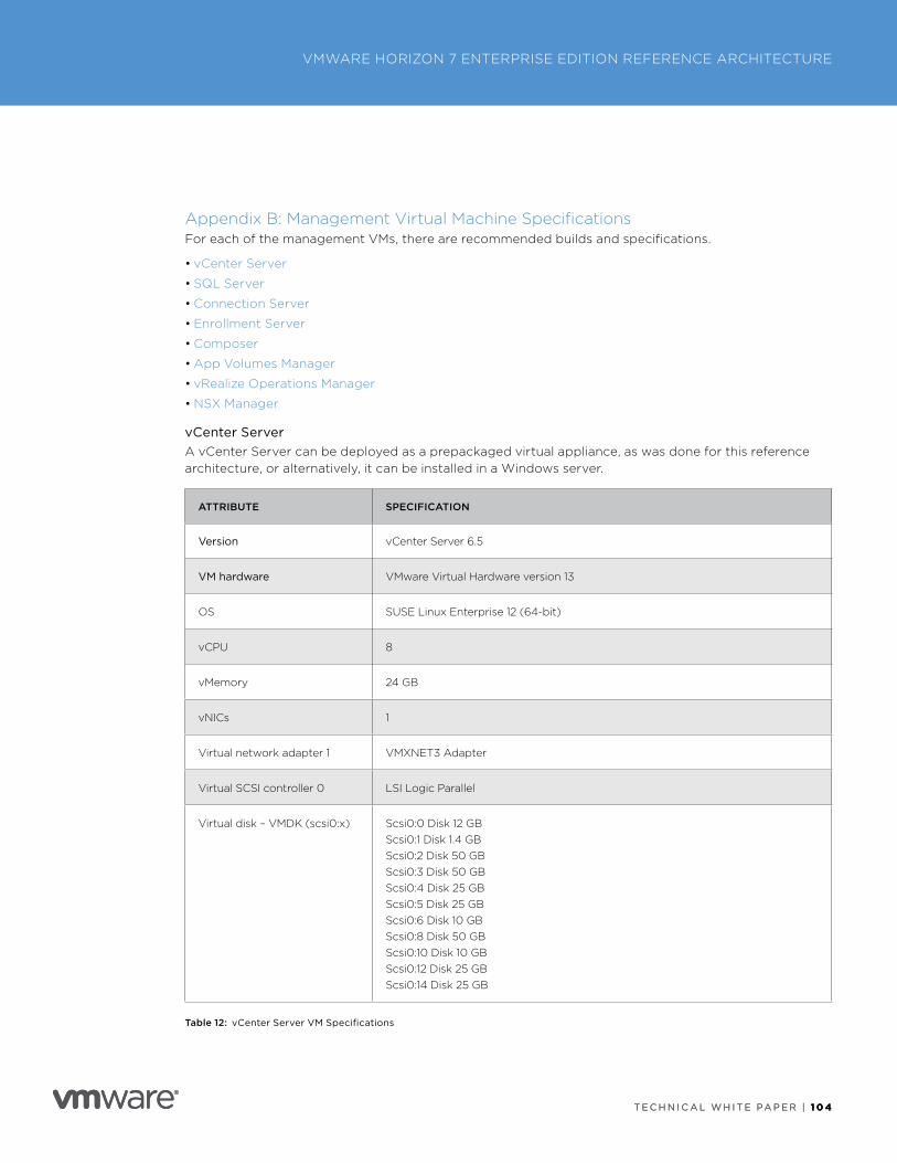
T E C H N I C A L W H I T E PA P E R | 1 0 4
VMWARE HORIZON 7 ENTERPRISE EDITION REFERENCE ARCHITECTURE
T E C H N I C A L W H I T E PA P E R | 1 0 4
Appendix B: Management Virtual Machine SpecificationsFor each of the management VMs, there are recommended builds and specifications .
• vCenter Server
• SQL Server
• Connection Server
• Enrollment Server
• Composer
• App Volumes Manager
• vRealize Operations Manager
• NSX Manager
vCenter Server A vCenter Server can be deployed as a prepackaged virtual appliance, as was done for this reference architecture, or alternatively, it can be installed in a Windows server .
ATTRIBUTE SPECIFICATION
Version vCenter Server 6 .5
VM hardware VMware Virtual Hardware version 13
OS SUSE Linux Enterprise 12 (64-bit)
vCPU 8
vMemory 24 GB
vNICs 1
Virtual network adapter 1 VMXNET3 Adapter
Virtual SCSI controller 0 LSI Logic Parallel
Virtual disk – VMDK (scsi0:x) Scsi0:0 Disk 12 GBScsi0:1 Disk 1 .4 GBScsi0:2 Disk 50 GBScsi0:3 Disk 50 GBScsi0:4 Disk 25 GBScsi0:5 Disk 25 GBScsi0:6 Disk 10 GBScsi0:8 Disk 50 GBScsi0:10 Disk 10 GBScsi0:12 Disk 25 GBScsi0:14 Disk 25 GB
Table 12: vCenter Server VM Specifications
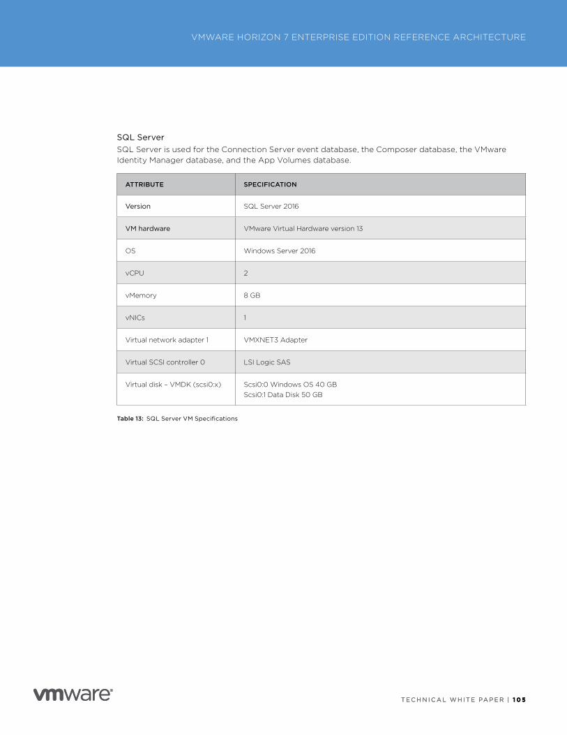
T E C H N I C A L W H I T E PA P E R | 1 0 5
VMWARE HORIZON 7 ENTERPRISE EDITION REFERENCE ARCHITECTURE
T E C H N I C A L W H I T E PA P E R | 1 0 5
SQL ServerSQL Server is used for the Connection Server event database, the Composer database, the VMware Identity Manager database, and the App Volumes database .
ATTRIBUTE SPECIFICATION
Version SQL Server 2016
VM hardware VMware Virtual Hardware version 13
OS Windows Server 2016
vCPU 2
vMemory 8 GB
vNICs 1
Virtual network adapter 1 VMXNET3 Adapter
Virtual SCSI controller 0 LSI Logic SAS
Virtual disk – VMDK (scsi0:x) Scsi0:0 Windows OS 40 GBScsi0:1 Data Disk 50 GB
Table 13: SQL Server VM Specifications
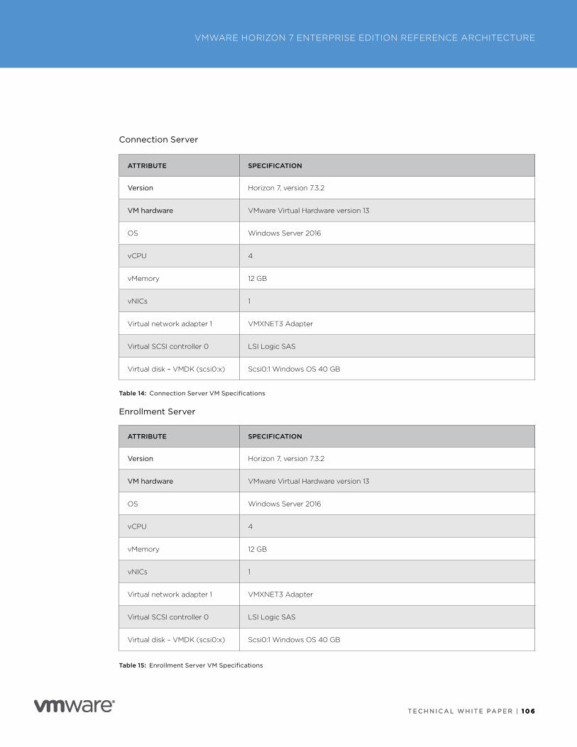
T E C H N I C A L W H I T E PA P E R | 1 0 6
VMWARE HORIZON 7 ENTERPRISE EDITION REFERENCE ARCHITECTURE
T E C H N I C A L W H I T E PA P E R | 1 0 6
Connection Server
ATTRIBUTE SPECIFICATION
Version Horizon 7, version 7 .3 .2
VM hardware VMware Virtual Hardware version 13
OS Windows Server 2016
vCPU 4
vMemory 12 GB
vNICs 1
Virtual network adapter 1 VMXNET3 Adapter
Virtual SCSI controller 0 LSI Logic SAS
Virtual disk – VMDK (scsi0:x) Scsi0:1 Windows OS 40 GB
Table 14: Connection Server VM Specifications
Enrollment Server
ATTRIBUTE SPECIFICATION
Version Horizon 7, version 7 .3 .2
VM hardware VMware Virtual Hardware version 13
OS Windows Server 2016
vCPU 4
vMemory 12 GB
vNICs 1
Virtual network adapter 1 VMXNET3 Adapter
Virtual SCSI controller 0 LSI Logic SAS
Virtual disk – VMDK (scsi0:x) Scsi0:1 Windows OS 40 GB
Table 15: Enrollment Server VM Specifications
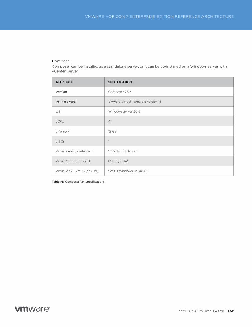
T E C H N I C A L W H I T E PA P E R | 1 07
VMWARE HORIZON 7 ENTERPRISE EDITION REFERENCE ARCHITECTURE
T E C H N I C A L W H I T E PA P E R | 1 07
ComposerComposer can be installed as a standalone server, or it can be co-installed on a Windows server with vCenter Server .
ATTRIBUTE SPECIFICATION
Version Composer 7 .3 .2
VM hardware VMware Virtual Hardware version 13
OS Windows Server 2016
vCPU 4
vMemory 12 GB
vNICs 1
Virtual network adapter 1 VMXNET3 Adapter
Virtual SCSI controller 0 LSI Logic SAS
Virtual disk – VMDK (scsi0:x) Scsi0:1 Windows OS 40 GB
Table 16: Composer VM Specifications
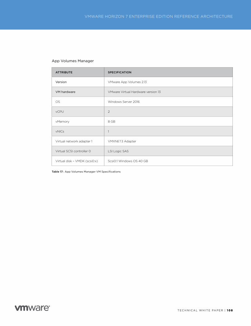
T E C H N I C A L W H I T E PA P E R | 1 0 8
VMWARE HORIZON 7 ENTERPRISE EDITION REFERENCE ARCHITECTURE
T E C H N I C A L W H I T E PA P E R | 1 0 8
App Volumes Manager
ATTRIBUTE SPECIFICATION
Version VMware App Volumes 2 .13
VM hardware VMware Virtual Hardware version 13
OS Windows Server 2016
vCPU 2
vMemory 8 GB
vNICs 1
Virtual network adapter 1 VMXNET3 Adapter
Virtual SCSI controller 0 LSI Logic SAS
Virtual disk – VMDK (scsi0:x) Scsi0:1 Windows OS 40 GB
Table 17: App Volumes Manager VM Specifications
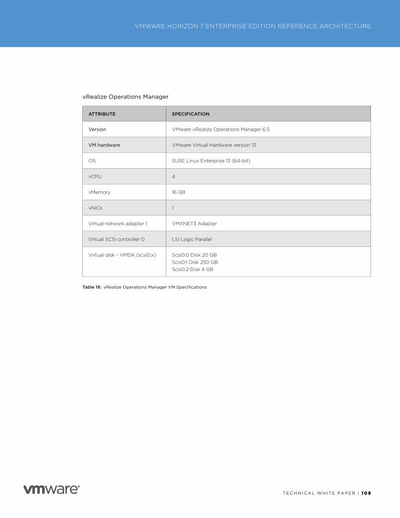
T E C H N I C A L W H I T E PA P E R | 1 0 9
VMWARE HORIZON 7 ENTERPRISE EDITION REFERENCE ARCHITECTURE
T E C H N I C A L W H I T E PA P E R | 1 0 9
vRealize Operations Manager
ATTRIBUTE SPECIFICATION
Version VMware vRealize Operations Manager 6 .5
VM hardware VMware Virtual Hardware version 13
OS SUSE Linux Enterprise 13 (64-bit)
vCPU 4
vMemory 16 GB
vNICs 1
Virtual network adapter 1 VMXNET3 Adapter
Virtual SCSI controller 0 LSI Logic Parallel
Virtual disk – VMDK (scsi0:x) Scsi0:0 Disk 20 GBScsi0:1 Disk 250 GBScsi0:2 Disk 4 GB
Table 18: vRealize Operations Manager VM Specifications

T E C H N I C A L W H I T E PA P E R | 1 1 0
VMWARE HORIZON 7 ENTERPRISE EDITION REFERENCE ARCHITECTURE
T E C H N I C A L W H I T E PA P E R | 1 1 0
NSX Manager
ATTRIBUTE SPECIFICATION
Version NSX Manager 6 .3 .5
VM hardware VMware Virtual Hardware version 13
OS Other Linux (64-bit)
vCPU 4
vMemory 16 GB
vNICs 1
Virtual network adapter 1 VMXNET3 Adapter
Virtual SCSI controller 0 LSI Logic Parallel
Virtual disk – VMDK (scsi0:x) Scsi0:0 Disk 60 GB
Table 19: NSX Manager VM Specifications
T E C H N I C A L W H I T E PA P E R | 1 1 1
VMWARE HORIZON 7 ENTERPRISE EDITION REFERENCE ARCHITECTURE
T E C H N I C A L W H I T E PA P E R | 1 1 1
Appendix C: Horizon 7 Installation and ConfigurationThis appendix provides an overview of the Horizon 7 deployment process, points to specific documents for detailed instructions, and lists certain settings that were used in this reference architecture .
Installation Prerequisites Before starting, certain other infrastructure components must be in place and configured:
• Management vSphere cluster
• VDI vSphere cluster
• Windows 2016 RDSH VM template
• Active Directory
• DNS
• DHCP
• Certificate Authority
• Load balancer
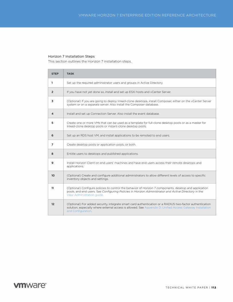
T E C H N I C A L W H I T E PA P E R | 1 1 2
VMWARE HORIZON 7 ENTERPRISE EDITION REFERENCE ARCHITECTURE
T E C H N I C A L W H I T E PA P E R | 1 1 2
Horizon 7 Installation StepsThis section outlines the Horizon 7 installation steps .
STEP TASK
1 Set up the required administrator users and groups in Active Directory .
2 If you have not yet done so, install and set up ESXi hosts and vCenter Server .
3 (Optional) If you are going to deploy linked-clone desktops, install Composer, either on the vCenter Server system or on a separate server . Also install the Composer database .
4 Install and set up Connection Server . Also install the event database .
5 Create one or more VMs that can be used as a template for full-clone desktop pools or as a master for linked-clone desktop pools or instant-clone desktop pools .
6 Set up an RDS host VM, and install applications to be remoted to end users .
7 Create desktop pools or application pools, or both .
8 Entitle users to desktops and published applications .
9 Install Horizon Client on end users’ machines and have end users access their remote desktops and applications .
10 (Optional) Create and configure additional administrators to allow different levels of access to specific inventory objects and settings .
11 (Optional) Configure policies to control the behavior of Horizon 7 components, desktop and application pools, and end users . See Configuring Policies in Horizon Administrator and Active Directory in the View Administration guide .
12 (Optional) For added security, integrate smart card authentication or a RADIUS two-factor authentication solution, especially where external access is allowed . See Appendix D: Unified Access Gateway Installation and Configuration .
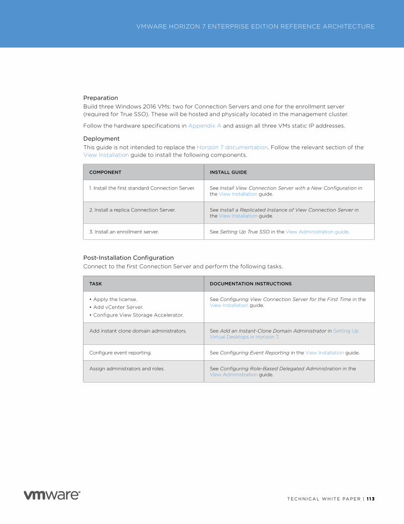
T E C H N I C A L W H I T E PA P E R | 1 1 3
VMWARE HORIZON 7 ENTERPRISE EDITION REFERENCE ARCHITECTURE
T E C H N I C A L W H I T E PA P E R | 1 1 3
PreparationBuild three Windows 2016 VMs: two for Connection Servers and one for the enrollment server (required for True SSO) . These will be hosted and physically located in the management cluster .
Follow the hardware specifications in Appendix A and assign all three VMs static IP addresses .
DeploymentThis guide is not intended to replace the Horizon 7 documentation . Follow the relevant section of the View Installation guide to install the following components .
COMPONENT INSTALL GUIDE
1 . Install the first standard Connection Server . See Install View Connection Server with a New Configuration in the View Installation guide .
2 . Install a replica Connection Server . See Install a Replicated Instance of View Connection Server in the View Installation guide .
3 . Install an enrollment server . See Setting Up True SSO in the View Administration guide .
Post-Installation ConfigurationConnect to the first Connection Server and perform the following tasks .
TASK DOCUMENTATION INSTRUCTIONS
• Apply the license .
• Add vCenter Server .
• Configure View Storage Accelerator .
See Configuring View Connection Server for the First Time in the View Installation guide .
Add instant clone domain administrators . See Add an Instant-Clone Domain Administrator in Setting Up Virtual Desktops in Horizon 7 .
Configure event reporting . See Configuring Event Reporting in the View Installation guide .
Assign administrators and roles . See Configuring Role-Based Delegated Administration in the View Administration guide .
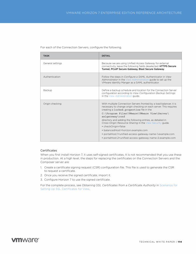
T E C H N I C A L W H I T E PA P E R | 1 1 4
VMWARE HORIZON 7 ENTERPRISE EDITION REFERENCE ARCHITECTURE
T E C H N I C A L W H I T E PA P E R | 1 1 4
For each of the Connection Servers, configure the following .
TASK DETAIL
General settings Because we are using Unified Access Gateway for external connectivity, leave the following fields deselected: HTTPS Secure Tunnel, PCoIP Secure Gateway, Blast Secure Gateway .
Authentication Follow the steps in Configure a SAML Authenticator in View Administrator in the View Administration guide to set up the VMware Identity Manger as a SAML authenticator .
Backup Define a backup schedule and location for the Connection Server configuration according to View Configuration Backup Settings in the View Administration guide .
Origin checking With multiple Connection Servers fronted by a load balancer, it is necessary to change origin checking on each server . This requires creating a locked.properties file in the
C:\Program Files\VMware\VMware View\Server\sslgateway\conf
directory and adding the following entries, as detailed in Cross-Origin Resource Sharing in the View Security guide .• checkOrigin=false
• balancedHost=horizon .example .com
• portalHost .1=unified-access-gateway-name-1 .example .com
• portalHost .2=unified-access-gateway-name-2 .example .com
CertificatesWhen you first install Horizon 7, it uses self-signed certificates . It is not recommended that you use these in production . At a high level, the steps for replacing the certificates on the Connection Servers and the Composer server are:
1 . Create a certificate signing request (CSR) configuration file . This file is used to generate the CSR to request a certificate .
2 . Once you receive the signed certificate, import it .
3 . Configure Horizon 7 to use the signed certificate .
For the complete process, see Obtaining SSL Certificates from a Certificate Authority in Scenarios for Setting Up SSL Certificates for View .
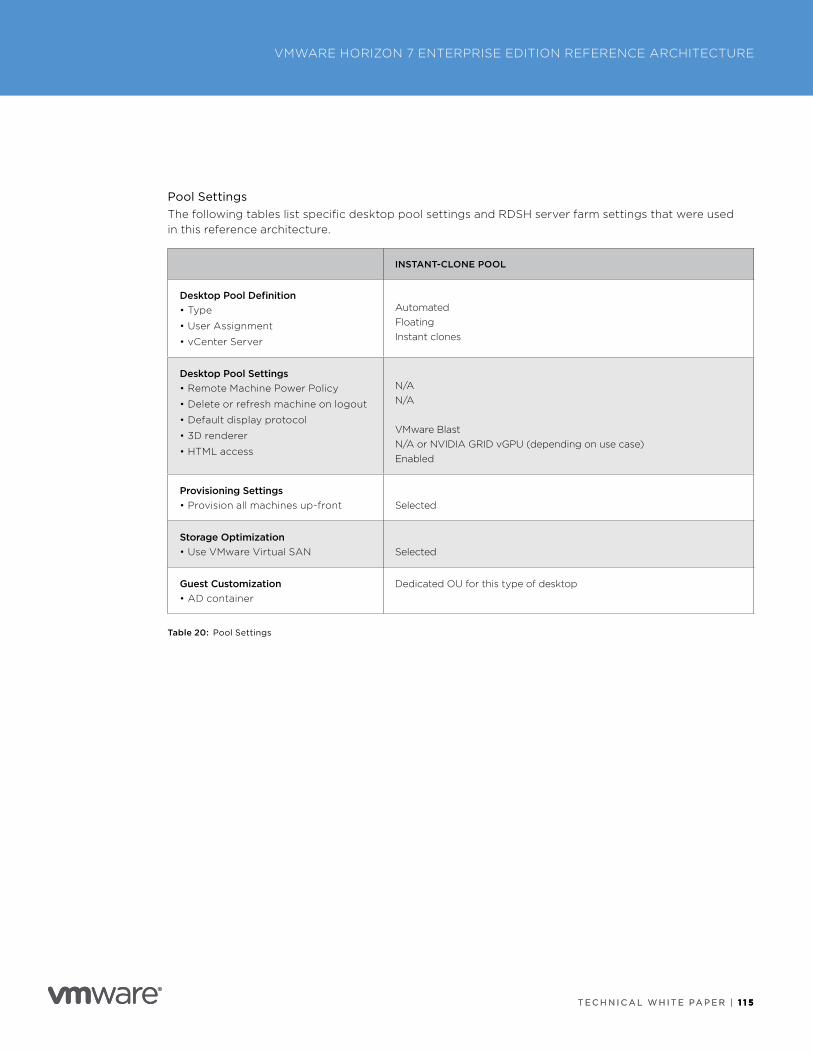
T E C H N I C A L W H I T E PA P E R | 1 1 5
VMWARE HORIZON 7 ENTERPRISE EDITION REFERENCE ARCHITECTURE
T E C H N I C A L W H I T E PA P E R | 1 1 5
Pool SettingsThe following tables list specific desktop pool settings and RDSH server farm settings that were used in this reference architecture .
INSTANT-CLONE POOL
Desktop Pool Definition• Type
• User Assignment
• vCenter Server
AutomatedFloatingInstant clones
Desktop Pool Settings• Remote Machine Power Policy
• Delete or refresh machine on logout
• Default display protocol
• 3D renderer
• HTML access
N/AN/A
VMware BlastN/A or NVIDIA GRID vGPU (depending on use case)Enabled
Provisioning Settings• Provision all machines up-front Selected
Storage Optimization• Use VMware Virtual SAN Selected
Guest Customization• AD container
Dedicated OU for this type of desktop
Table 20: Pool Settings
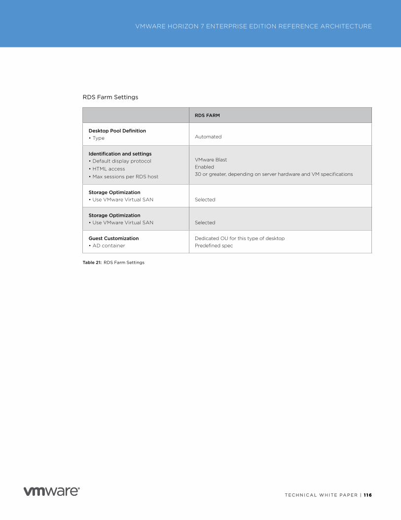
T E C H N I C A L W H I T E PA P E R | 1 1 6
VMWARE HORIZON 7 ENTERPRISE EDITION REFERENCE ARCHITECTURE
T E C H N I C A L W H I T E PA P E R | 1 1 6
RDS Farm Settings
RDS FARM
Desktop Pool Definition• Type
Automated
Identification and settings• Default display protocol
• HTML access
• Max sessions per RDS host
VMware BlastEnabled30 or greater, depending on server hardware and VM specifications
Storage Optimization• Use VMware Virtual SAN Selected
Storage Optimization• Use VMware Virtual SAN Selected
Guest Customization• AD container
Dedicated OU for this type of desktopPredefined spec
Table 21: RDS Farm Settings
T E C H N I C A L W H I T E PA P E R | 1 1 7
VMWARE HORIZON 7 ENTERPRISE EDITION REFERENCE ARCHITECTURE
T E C H N I C A L W H I T E PA P E R | 1 1 7
Appendix D: Unified Access Gateway Installation and ConfigurationTo facilitate a successful installation of Unified Access Gateway, various prerequisites must be in place prior to performing an installation . The following section details the prerequisites and deployment options available that satisfy the design requirements .
Note: Only the options that satisfy the design requirements are described here . Other options are available and documented within the Unified Access Gateway documentation .
Appliance RequirementsEach Unified Access Gateway appliance has the following requirements:
• 4 GB RAM
• 2 vCPUs
• 1–3 NICs
• 20 GB disk space
Deployment OptionsIn this section, we briefly discuss the two supported methods of deploying Unified Access Gateway and then detail the optimal solution to satisfy the design requirements .
vSphere OVF Template and Administration Console
Unified Access Gateway can be deployed by running the OVF wizard and responding to various deployment questions . This method requires responses from an IT administrator during deployment . If you use this method, the Unified Access Gateway is not production-ready on first boot and requires post-deployment configuration using the administration console . The required configuration tasks can be performed either manually or by importing a configuration file from another Unified Access Gateway appliance .
PowerShell Script
The PowerShell method ensures that the Unified Access Gateway virtual appliance is production-ready on first boot . This method uses the VMware OVF Tool command-line utility in the background . The IT administrator updates an INI file with the required configuration settings and then deploys the Unified Access Gateway by entering a simple deployment command in PowerShell ( .\uagdeploy.ps1 .\<name>.ini) .
Design Decision: The PowerShell method is used because it satisfies most deployment scenarios and does not require the IT administrator to enter complex OVF Tool commands to complete the deployment .
To download the PowerShell script and sample INI files, see Using PowerShell to Deploy VMware Unified Access Gateway .
T E C H N I C A L W H I T E PA P E R | 1 1 8
VMWARE HORIZON 7 ENTERPRISE EDITION REFERENCE ARCHITECTURE
T E C H N I C A L W H I T E PA P E R | 1 1 8
Installation Prerequisites Before deploying a Unified Access Gateway appliance, you must verify that certain prerequisites are met .
Certificates
Certificates are used to secure communications between the endpoint and the Unified Access Gateway and between the Unified Access Gateway and the Connection Servers .
Password Requirement
Unified Access Gateway requires the IT administrator to define two passwords during installation: The first secures access to the REST API, and the second secures access to the Unified Access Gateway appliance console . The passwords must meet the minimum requirements listed in the Unified Access Gateway documentation .
vCenter Network Profiles
Regardless of the type of deployment chosen, vCenter Server network profiles are required for each network that the Unified Access Gateway is attached to . The network profile provides the following information:
• Default gateway
• Subnet mask
• Subnet
• DNS servers
• DNS domain
IP Address and Fully Qualified Domain Name (FQDN)
As previously discussed, the Unified Access Gateway in this scenario is configured with two NICs:
• Internet-facing IP address and external FQDN
• Back-end and management IP address and FQDN
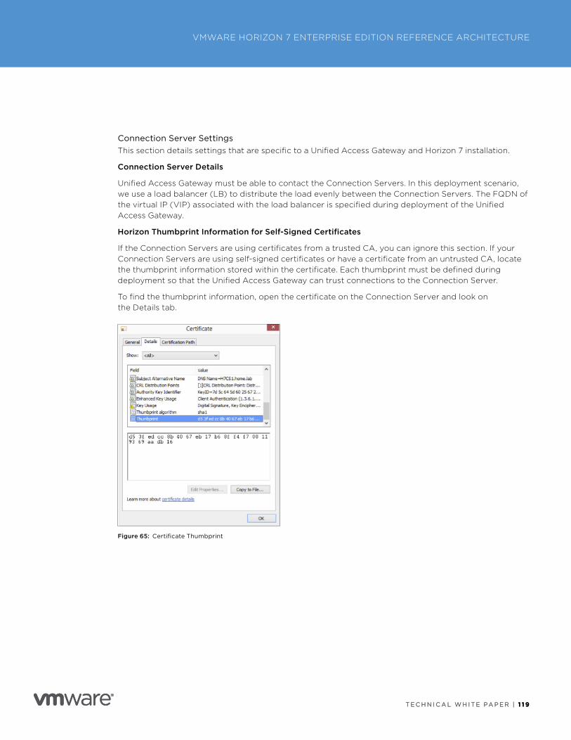
T E C H N I C A L W H I T E PA P E R | 1 1 9
VMWARE HORIZON 7 ENTERPRISE EDITION REFERENCE ARCHITECTURE
T E C H N I C A L W H I T E PA P E R | 1 1 9
Connection Server SettingsThis section details settings that are specific to a Unified Access Gateway and Horizon 7 installation .
Connection Server Details
Unified Access Gateway must be able to contact the Connection Servers . In this deployment scenario, we use a load balancer (LB) to distribute the load evenly between the Connection Servers . The FQDN of the virtual IP (VIP) associated with the load balancer is specified during deployment of the Unified Access Gateway .
Horizon Thumbprint Information for Self-Signed Certificates
If the Connection Servers are using certificates from a trusted CA, you can ignore this section . If your Connection Servers are using self-signed certificates or have a certificate from an untrusted CA, locate the thumbprint information stored within the certificate . Each thumbprint must be defined during deployment so that the Unified Access Gateway can trust connections to the Connection Server .
To find the thumbprint information, open the certificate on the Connection Server and look on the Details tab .
Figure 65: Certificate Thumbprint
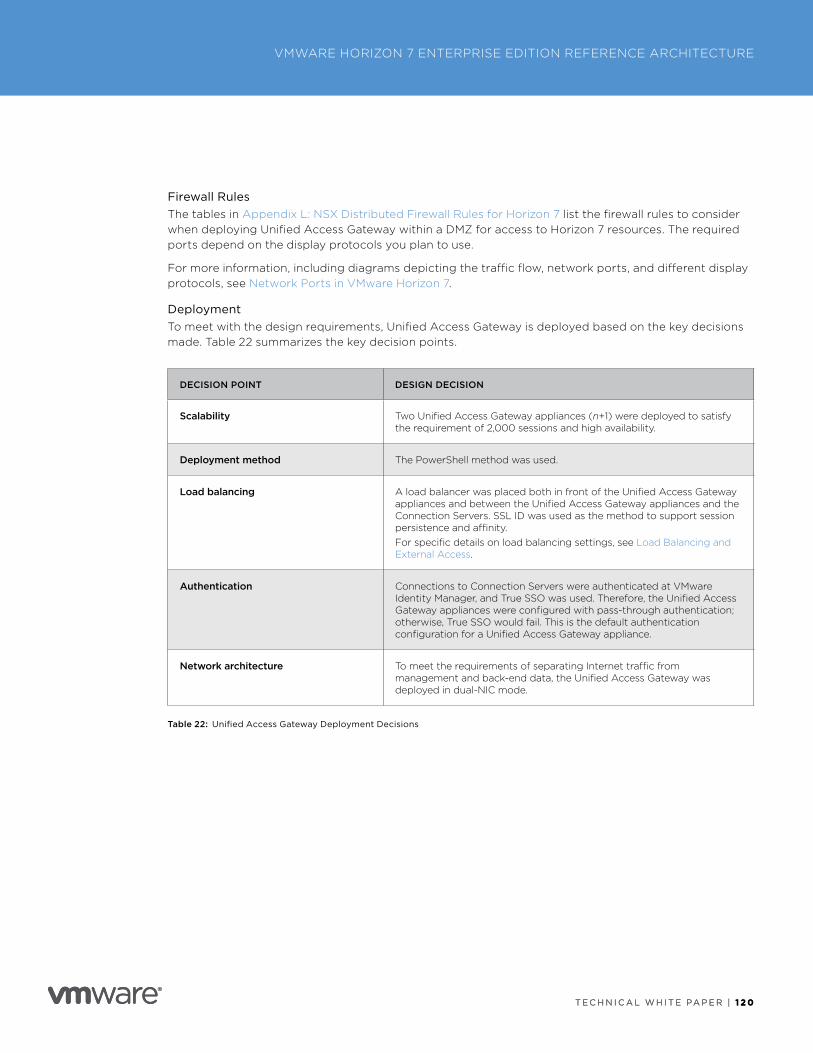
T E C H N I C A L W H I T E PA P E R | 1 2 0
VMWARE HORIZON 7 ENTERPRISE EDITION REFERENCE ARCHITECTURE
T E C H N I C A L W H I T E PA P E R | 1 2 0
Firewall RulesThe tables in Appendix L: NSX Distributed Firewall Rules for Horizon 7 list the firewall rules to consider when deploying Unified Access Gateway within a DMZ for access to Horizon 7 resources . The required ports depend on the display protocols you plan to use .
For more information, including diagrams depicting the traffic flow, network ports, and different display protocols, see Network Ports in VMware Horizon 7 .
DeploymentTo meet with the design requirements, Unified Access Gateway is deployed based on the key decisions made . Table 22 summarizes the key decision points .
DECISION POINT DESIGN DECISION
Scalability Two Unified Access Gateway appliances (n+1) were deployed to satisfy the requirement of 2,000 sessions and high availability .
Deployment method The PowerShell method was used .
Load balancing A load balancer was placed both in front of the Unified Access Gateway appliances and between the Unified Access Gateway appliances and the Connection Servers . SSL ID was used as the method to support session persistence and affinity .For specific details on load balancing settings, see Load Balancing and External Access .
Authentication Connections to Connection Servers were authenticated at VMware Identity Manager, and True SSO was used . Therefore, the Unified Access Gateway appliances were configured with pass-through authentication; otherwise, True SSO would fail . This is the default authentication configuration for a Unified Access Gateway appliance .
Network architecture To meet the requirements of separating Internet traffic from management and back-end data, the Unified Access Gateway was deployed in dual-NIC mode .
Table 22: Unified Access Gateway Deployment Decisions
T E C H N I C A L W H I T E PA P E R | 1 2 1
VMWARE HORIZON 7 ENTERPRISE EDITION REFERENCE ARCHITECTURE
T E C H N I C A L W H I T E PA P E R | 1 2 1
Deployment Steps Follow these high-level steps in the order listed .
1 . Download and install the latest OVF Tools from my .vmware .com .
2 . Download the latest Unified Access Gateway OVA file from my .vmware .com .
3 . Go to Using PowerShell to Deploy VMware Unified Access Gateway, and download the uagdeploy-310-v3.zip or later file and extract the contents .
4 . Make a copy, and edit one of the sample INI files (such as uag2-advanced.ini) .
5 . Enter your information as required for the [General] and [SSLCert] sections .
6 . Edit the edge service sections as required (for example, the [Horizon] section) .
7 . Run the script in PowerShell using the following command:
.\uagdeploy.psl .\<filename>.ini
8 . After the process is complete, wait a few minutes for the Unified Access Gateway appliance to boot completely .
You can monitor this process in the vSphere Web Client to see when the assigned IP address is reported on the summary page for the VM .
Log in to the Unified Access Gateway administration console to check the status of the configuration and service and to add or change the configuration . If you change any settings, such as adding a new edge service, remember to export the settings and update your INI file to reflect your changes .
For more information on deploying with the PowerShell method and the vSphere OVF Template method, see:
• VMware Unified Access Gateway Technical Deep Dive blog
• Using PowerShell to Deploy VMware Unified Access Gateway
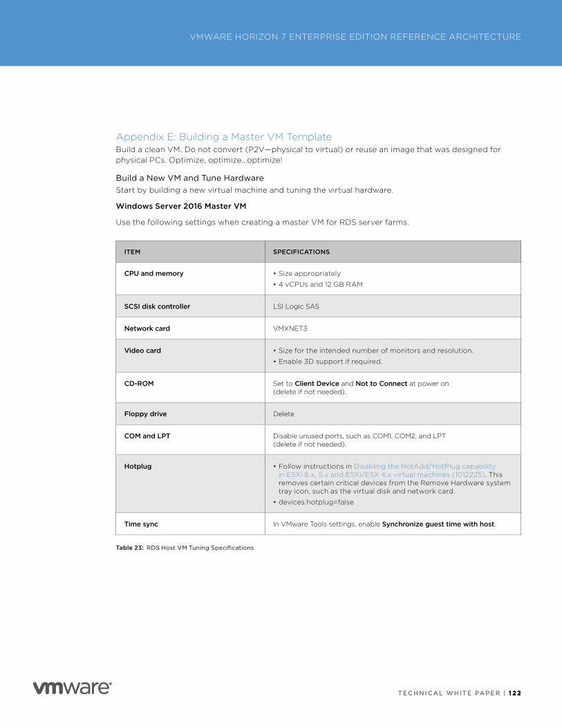
T E C H N I C A L W H I T E PA P E R | 1 2 2
VMWARE HORIZON 7 ENTERPRISE EDITION REFERENCE ARCHITECTURE
T E C H N I C A L W H I T E PA P E R | 1 2 2
Appendix E: Building a Master VM TemplateBuild a clean VM . Do not convert (P2V—physical to virtual) or reuse an image that was designed for physical PCs . Optimize, optimize…optimize!
Build a New VM and Tune HardwareStart by building a new virtual machine and tuning the virtual hardware .
Windows Server 2016 Master VM
Use the following settings when creating a master VM for RDS server farms .
ITEM SPECIFICATIONS
CPU and memory • Size appropriately
• 4 vCPUs and 12 GB RAM
SCSI disk controller LSI Logic SAS
Network card VMXNET3
Video card • Size for the intended number of monitors and resolution .
• Enable 3D support if required .
CD-ROM Set to Client Device and Not to Connect at power on (delete if not needed) .
Floppy drive Delete
COM and LPT Disable unused ports, such as COM1, COM2, and LPT (delete if not needed) .
Hotplug • Follow instructions in Disabling the HotAdd/HotPlug capability in ESXi 6 .x, 5 .x and ESXi/ESX 4 .x virtual machines (1012225) . This removes certain critical devices from the Remove Hardware system tray icon, such as the virtual disk and network card .
• devices .hotplug=false
Time sync In VMware Tools settings, enable Synchronize guest time with host .
Table 23: RDS Host VM Tuning Specifications
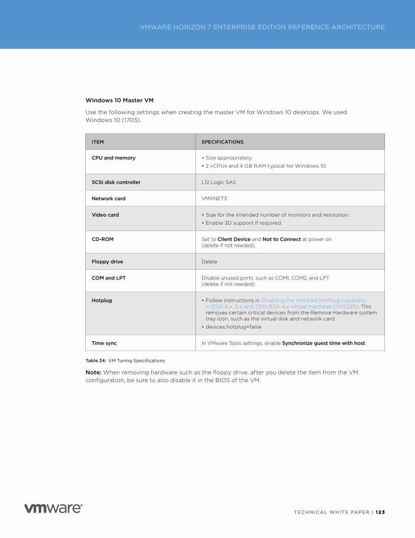
T E C H N I C A L W H I T E PA P E R | 1 2 3
VMWARE HORIZON 7 ENTERPRISE EDITION REFERENCE ARCHITECTURE
T E C H N I C A L W H I T E PA P E R | 1 2 3
Windows 10 Master VM
Use the following settings when creating the master VM for Windows 10 desktops . We used Windows 10 (1703) .
ITEM SPECIFICATIONS
CPU and memory • Size appropriately
• 2 vCPUs and 4 GB RAM typical for Windows 10
SCSI disk controller LSI Logic SAS
Network card VMXNET3
Video card • Size for the intended number of monitors and resolution .
• Enable 3D support if required .
CD-ROM Set to Client Device and Not to Connect at power on (delete if not needed) .
Floppy drive Delete
COM and LPT Disable unused ports, such as COM1, COM2, and LPT (delete if not needed) .
Hotplug • Follow instructions in Disabling the HotAdd/HotPlug capability in ESXi 6 .x, 5 .x and ESXi/ESX 4 .x virtual machines (1012225) . This removes certain critical devices from the Remove Hardware system tray icon, such as the virtual disk and network card .
• devices .hotplug=false
Time sync In VMware Tools settings, enable Synchronize guest time with host .
Table 24: VM Tuning Specifications
Note: When removing hardware such as the floppy drive, after you delete the item from the VM configuration, be sure to also disable it in the BIOS of the VM .
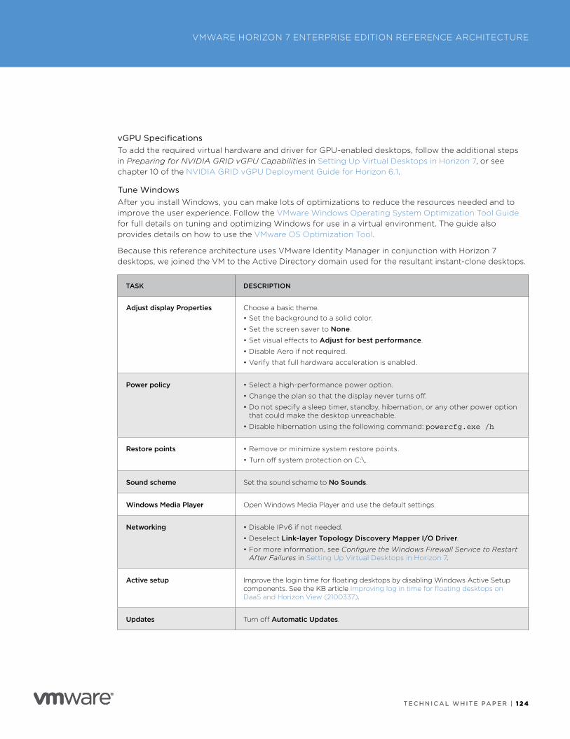
T E C H N I C A L W H I T E PA P E R | 1 2 4
VMWARE HORIZON 7 ENTERPRISE EDITION REFERENCE ARCHITECTURE
T E C H N I C A L W H I T E PA P E R | 1 2 4
vGPU SpecificationsTo add the required virtual hardware and driver for GPU-enabled desktops, follow the additional steps in Preparing for NVIDIA GRID vGPU Capabilities in Setting Up Virtual Desktops in Horizon 7, or see chapter 10 of the NVIDIA GRID vGPU Deployment Guide for Horizon 6 .1 .
Tune WindowsAfter you install Windows, you can make lots of optimizations to reduce the resources needed and to improve the user experience . Follow the VMware Windows Operating System Optimization Tool Guide for full details on tuning and optimizing Windows for use in a virtual environment . The guide also provides details on how to use the VMware OS Optimization Tool .
Because this reference architecture uses VMware Identity Manager in conjunction with Horizon 7 desktops, we joined the VM to the Active Directory domain used for the resultant instant-clone desktops .
TASK DESCRIPTION
Adjust display Properties Choose a basic theme .• Set the background to a solid color .
• Set the screen saver to None .
• Set visual effects to Adjust for best performance .
• Disable Aero if not required .
• Verify that full hardware acceleration is enabled .
Power policy • Select a high-performance power option .
• Change the plan so that the display never turns off .
• Do not specify a sleep timer, standby, hibernation, or any other power option that could make the desktop unreachable .
• Disable hibernation using the following command: powercfg.exe /h
Restore points • Remove or minimize system restore points .
• Turn off system protection on C:\ .
Sound scheme Set the sound scheme to No Sounds .
Windows Media Player Open Windows Media Player and use the default settings .
Networking • Disable IPv6 if not needed .
• Deselect Link-layer Topology Discovery Mapper I/O Driver .• For more information, see Configure the Windows Firewall Service to Restart
After Failures in Setting Up Virtual Desktops in Horizon 7 .
Active setup Improve the login time for floating desktops by disabling Windows Active Setup components . See the KB article Improving log in time for floating desktops on DaaS and Horizon View (2100337) .
Updates Turn off Automatic Updates .
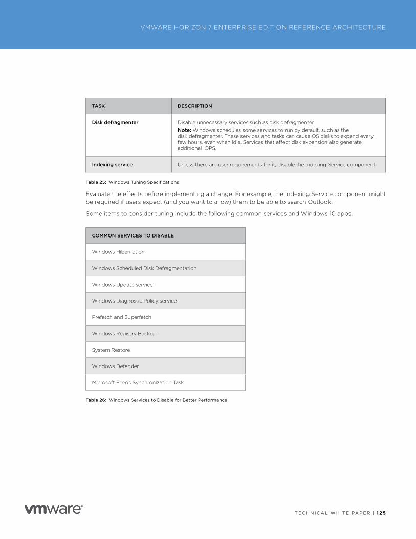
T E C H N I C A L W H I T E PA P E R | 1 2 5
VMWARE HORIZON 7 ENTERPRISE EDITION REFERENCE ARCHITECTURE
T E C H N I C A L W H I T E PA P E R | 1 2 5
TASK DESCRIPTION
Disk defragmenter Disable unnecessary services such as disk defragmenter .Note: Windows schedules some services to run by default, such as the disk defragmenter . These services and tasks can cause OS disks to expand every few hours, even when idle . Services that affect disk expansion also generate additional IOPS .
Indexing service Unless there are user requirements for it, disable the Indexing Service component .
Table 25: Windows Tuning Specifications
Evaluate the effects before implementing a change . For example, the Indexing Service component might be required if users expect (and you want to allow) them to be able to search Outlook .
Some items to consider tuning include the following common services and Windows 10 apps .
COMMON SERVICES TO DISABLE
Windows Hibernation
Windows Scheduled Disk Defragmentation
Windows Update service
Windows Diagnostic Policy service
Prefetch and Superfetch
Windows Registry Backup
System Restore
Windows Defender
Microsoft Feeds Synchronization Task
Table 26: Windows Services to Disable for Better Performance
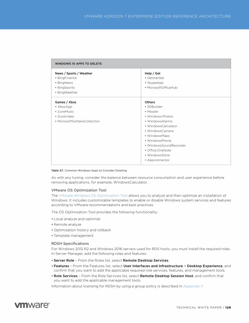
T E C H N I C A L W H I T E PA P E R | 1 2 6
VMWARE HORIZON 7 ENTERPRISE EDITION REFERENCE ARCHITECTURE
T E C H N I C A L W H I T E PA P E R | 1 2 6
WINDOWS 10 APPS TO DELETE
News / Sports / Weather• BingFinance
• BingNews
• BingSports
• BingWeather
Help / Get• Getstarted
• SkypeApp
• MicrosoftOfficeHub
Games / Xbox• XboxApp
• ZuneMusic
• ZuneVideo
• MicrosoftSolitaireCollection
Others• 3DBuilder
• People
• Windows .Photos
• WindowsAlarms
• WindowsCalculator
• WindowsCamera
• WindowsMaps
• WindowsPhone
• WindowsSoundRecorder
• Office .OneNote
• WindowsStore
• Appconnector
Table 27: Common Windows Apps to Consider Deleting
As with any tuning, consider the balance between resource consumption and user experience before removing applications, for example, WindowsCalculator .
VMware OS Optimization ToolThe VMware Windows OS Optimization Tool allows you to analyze and then optimize an installation of Windows . It includes customizable templates to enable or disable Windows system services and features according to VMware recommendations and best practices .
The OS Optimization Tool provides the following functionality:
• Local analyze and optimize
• Remote analyze
• Optimization history and rollback
• Template management
RDSH SpecificationsFor Windows 2012 R2 and Windows 2016 servers used for RDS hosts, you must install the required roles . In Server Manager, add the following roles and features:
• Server Role – From the Roles list, select Remote Desktop Services .
• Features – From the Features list, select User Interfaces and Infrastructure > Desktop Experience, and confirm that you want to add the applicable required role services, features, and management tools .
• Role Services – From the Role Services list, select Remote Desktop Session Host, and confirm that you want to add the applicable management tools .
Information about licensing for RDSH by using a group policy is described in Appendix F .
T E C H N I C A L W H I T E PA P E R | 1 2 7
VMWARE HORIZON 7 ENTERPRISE EDITION REFERENCE ARCHITECTURE
T E C H N I C A L W H I T E PA P E R | 1 2 7
ApplicationsAlthough our primary application-delivery mechanism is App Volumes, it might be desirable to install select applications in the master VM so that all clones get those applications in their base disk .
Many applications have integrated auto-update functionality . Install these applications and update them to the latest version, and then turn off or disable the auto-update functionality to prevent the clones from updating individually .
Antivirus Best Practices (If Not Using Endpoint Antivirus)Follow the best practices for using antivirus software on virtual desktops and RDS hosts as detailed in Antivirus Considerations in a VMware Horizon 7 Environment .
Install VMware Tools and AgentsWhen preparing a VM for use as a virtual desktop or RDS host, you must install the relevant product agents . The installation order is important, and if you update one agent, remove all subsequent agents and install their latest versions to maintain the installation order .
Agent Installation Order
1 . VMware Tools
2 . Horizon Agent
3 . User Environment Manager FlexEngine
4 . VMware Identity Manager Client
5 . App Volumes Agent
VMware Identity Manager Client
This agent enables virtual desktops to launch application types, such as ThinApps, that are delivered through VMware Identity Manager . Install from the command line, and specify the following parameters:
/v WORKSPACE_SERVER=”https://<WORKSPACE_SERVER_FQDN>” INSTALL_MODE=RUN_FROM_SHARE
Note: Replace the <WORKSPACE_SERVER_FQDN> with the server name that end users will use to access VMware Identity Manager . This might be the FQDN for the load balancer, if a load balancer is used in front of multiple VMware Identity Manager appliances .
Horizon Agent
1 . Select IPv4 or IPv6 .
Agent, client, and Connection Servers must all use the same IP version .
2 . Select additional features, if required . See Horizon Agent Custom Setup Options in Setting Up Virtual Desktops in Horizon 7 .
3 . Select a cloning technology: Instant Clone .
4 . Enable Remote Desktop, if not already done .
• Give suitable security group access (for example, Domain Users) .
• Add firewall exceptions if enabling manually .
T E C H N I C A L W H I T E PA P E R | 1 2 8
VMWARE HORIZON 7 ENTERPRISE EDITION REFERENCE ARCHITECTURE
T E C H N I C A L W H I T E PA P E R | 1 2 8
FinalizeThe last step before we can use this VM is to clean up and take a vSphere snapshot .
1 . Cleanup:
• Delete all event logs .
• Delete all hidden update folders in C:\Windows .
Example: $NtUninstallKB893756$ (except $hf_mig$)• Turn off disk performance counters (diskperf –n) .
• Delete contents of C:\Windows\Temp\ .
• Run Disk Cleanup to remove temporary files, empty the Recycle Bin, and remove other unneeded files .
• Run Disk Defragmenter (you might have to temporarily re-enable the Optimize drives service) .
• Flush DNS, and release the DHCP IP address lease .
2 . Shut down the VM .
3 . Disconnect the CD-ROM and make sure no ISO is configured in the VM .
4 . Snapshot the VM .

T E C H N I C A L W H I T E PA P E R | 1 2 9
VMWARE HORIZON 7 ENTERPRISE EDITION REFERENCE ARCHITECTURE
T E C H N I C A L W H I T E PA P E R | 1 2 9
Appendix F: Group PoliciesYou can use standard Microsoft Group Policy Object settings to configure virtual desktops and applications . You can also use VMware-provided GPO administrative templates for fine-grained control of access to features .
• OU GPO Best Practices
• Common GPO Settings
• Desktop
• RDS Host OU Level
• User Configuration Settings
• User Environment Manager – Group Policy Settings
OU GPO Best PracticesUse the following guidelines when applying GPO settings:
• Reuse GPOs .
• Create separate OUs for users and computers .
• Ensure that each GPO is enabled or disabled for Computer and User settings .
• Group similar settings into one GPO .
• Understand the difference between monolithic and functional GPOs:
– Monolithic GPOs contain settings for many different areas and are quite large . All settings are in one place . Use monolithic GPOs for generic settings that apply to all users or computers .
– Functional GPOs contain a limited set of settings for a specific area . Functional GPOs are smaller GPOs that facilitate settings being defined for particular users or VMs .
• Link the GPOs to the OU structure (or site), and then use Security Groups to selectively apply these GPOs to particular users or computers .
• Use loopback replace to ensure that only the settings for the VM’s OU are applied to the session .
This appendix contains a list of group policy settings that would typically be applied (this is not an exhaustive list) . Most other settings can be applied through User Environment Manager policies . The download of Horizon 7 includes a VMware-Horizon-Extras-Bundle ZIP file that contains a set of group policy templates to assist in defining these and other GPO settings .
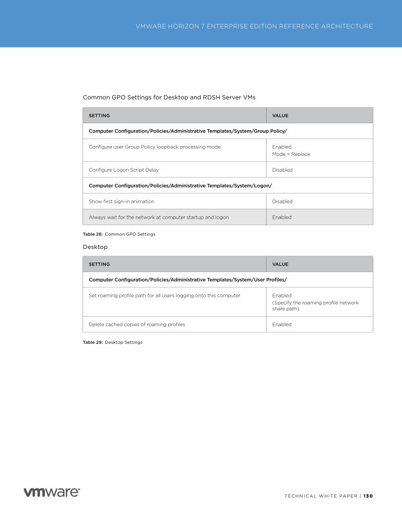
T E C H N I C A L W H I T E PA P E R | 1 3 0
VMWARE HORIZON 7 ENTERPRISE EDITION REFERENCE ARCHITECTURE
T E C H N I C A L W H I T E PA P E R | 1 3 0
Common GPO Settings for Desktop and RDSH Server VMs
SETTING VALUE
Computer Configuration/Policies/Administrative Templates/System/Group Policy/
Configure user Group Policy loopback processing mode EnabledMode = Replace
Configure Logon Script Delay Disabled
Computer Configuration/Policies/Administrative Templates/System/Logon/
Show first sign-in animation Disabled
Always wait for the network at computer startup and logon Enabled
Table 28: Common GPO Settings
Desktop
SETTING VALUE
Computer Configuration/Policies/Administrative Templates/System/User Profiles/
Set roaming profile path for all users logging onto this computer Enabled(Specify the roaming profile network share path) .
Delete cached copies of roaming profiles Enabled
Table 29: Desktop Settings
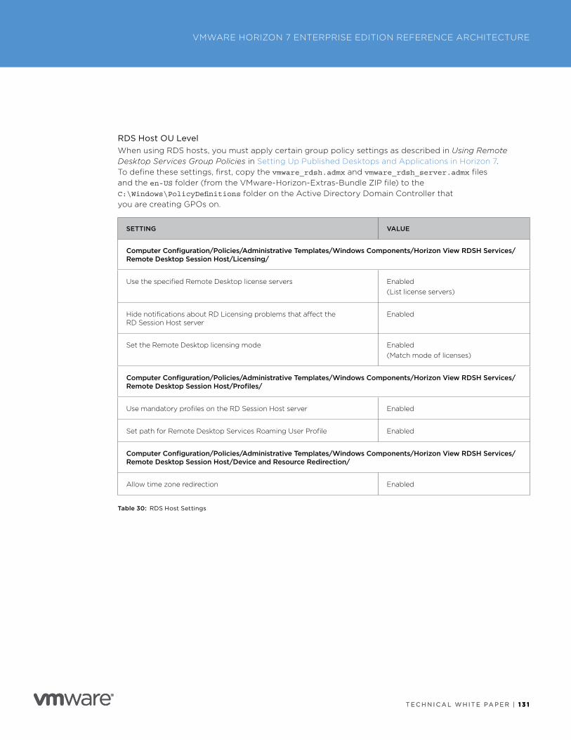
T E C H N I C A L W H I T E PA P E R | 1 3 1
VMWARE HORIZON 7 ENTERPRISE EDITION REFERENCE ARCHITECTURE
T E C H N I C A L W H I T E PA P E R | 1 3 1
RDS Host OU LevelWhen using RDS hosts, you must apply certain group policy settings as described in Using Remote Desktop Services Group Policies in Setting Up Published Desktops and Applications in Horizon 7 . To define these settings, first, copy the vmware_rdsh.admx and vmware_rdsh_server.admx files and the en-US folder (from the VMware-Horizon-Extras-Bundle ZIP file) to the C:\Windows\PolicyDefinitions folder on the Active Directory Domain Controller that you are creating GPOs on .
SETTING VALUE
Computer Configuration/Policies/Administrative Templates/Windows Components/Horizon View RDSH Services/Remote Desktop Session Host/Licensing/
Use the specified Remote Desktop license servers Enabled(List license servers)
Hide notifications about RD Licensing problems that affect the RD Session Host server
Enabled
Set the Remote Desktop licensing mode Enabled(Match mode of licenses)
Computer Configuration/Policies/Administrative Templates/Windows Components/Horizon View RDSH Services/Remote Desktop Session Host/Profiles/
Use mandatory profiles on the RD Session Host server Enabled
Set path for Remote Desktop Services Roaming User Profile Enabled
Computer Configuration/Policies/Administrative Templates/Windows Components/Horizon View RDSH Services/Remote Desktop Session Host/Device and Resource Redirection/
Allow time zone redirection Enabled
Table 30: RDS Host Settings
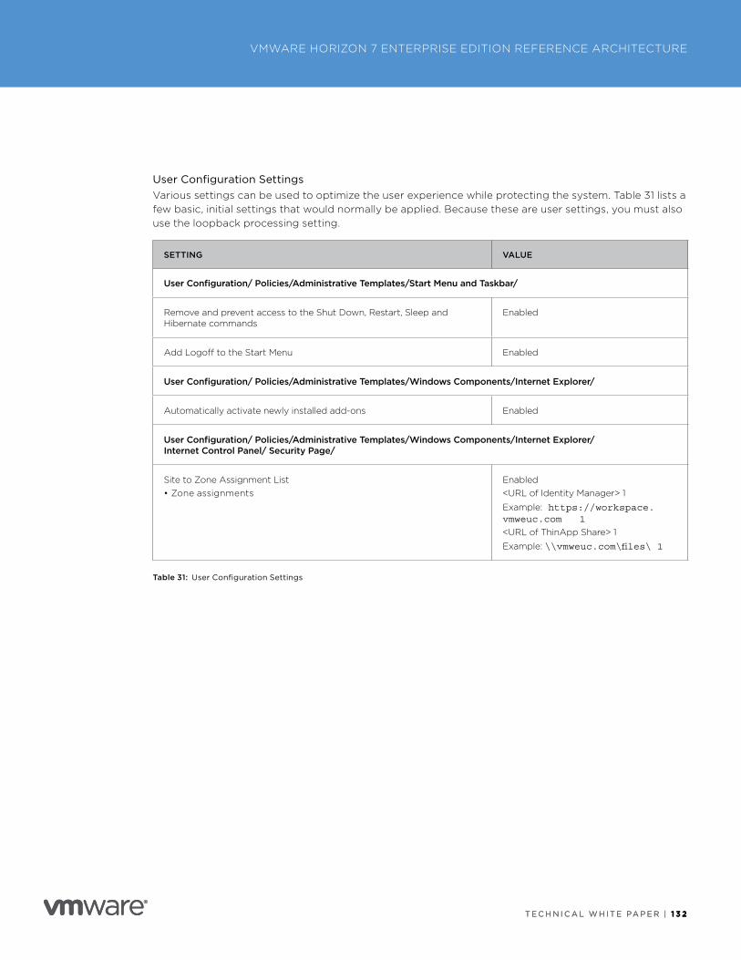
T E C H N I C A L W H I T E PA P E R | 1 3 2
VMWARE HORIZON 7 ENTERPRISE EDITION REFERENCE ARCHITECTURE
T E C H N I C A L W H I T E PA P E R | 1 3 2
User Configuration SettingsVarious settings can be used to optimize the user experience while protecting the system . Table 31 lists a few basic, initial settings that would normally be applied . Because these are user settings, you must also use the loopback processing setting .
SETTING VALUE
User Configuration/ Policies/Administrative Templates/Start Menu and Taskbar/
Remove and prevent access to the Shut Down, Restart, Sleep and Hibernate commands
Enabled
Add Logoff to the Start Menu Enabled
User Configuration/ Policies/Administrative Templates/Windows Components/Internet Explorer/
Automatically activate newly installed add-ons Enabled
User Configuration/ Policies/Administrative Templates/Windows Components/Internet Explorer/ Internet Control Panel/ Security Page/
Site to Zone Assignment List• Zone assignments
Enabled<URL of Identity Manager> 1
Example: https://workspace.vmweuc.com 1
<URL of ThinApp Share> 1
Example: \\vmweuc.com\files\ 1
Table 31: User Configuration Settings
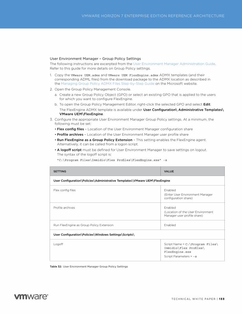
T E C H N I C A L W H I T E PA P E R | 1 3 3
VMWARE HORIZON 7 ENTERPRISE EDITION REFERENCE ARCHITECTURE
T E C H N I C A L W H I T E PA P E R | 1 3 3
User Environment Manager – Group Policy Settings The following instructions are excerpted from the User Environment Manager Administration Guide . Refer to this guide for more details on Group Policy settings .
1 . Copy the VMware UEM.admx and VMware UEM FlexEngine.admx ADMX templates (and their corresponding ADML files) from the download package to the ADMX location as described in the Managing Group Policy ADMX Files Step-by-Step Guide on the Microsoft website .
2 . Open the Group Policy Management Console .
a . Create a new Group Policy Object (GPO) or select an existing GPO that is applied to the users for which you want to configure FlexEngine .
b . To open the Group Policy Management Editor, right-click the selected GPO and select Edit .The FlexEngine ADMX template is available under User Configuration\ Administrative Templates\VMware UEM\FlexEngine .
3 . Configure the appropriate User Environment Manager Group Policy settings . At a minimum, the following must be set:
• Flex config files – Location of the User Environment Manager configuration share
• Profile archives – Location of the User Environment Manager user profile share
• Run FlexEngine as a Group Policy Extension – This setting enables the FlexEngine agent . Alternatively, it can be called from a logon script .
• A logoff script must be defined for User Environment Manager to save settings on logout . The syntax of the logoff script is:
"C:\Program Files\Immidio\Flex Profiles\FlexEngine.exe" -s
SETTING VALUE
User Configuration\Policies\Administrative Templates\VMware UEM\FlexEngine
Flex config files Enabled(Enter User Environment Manager configuration share)
Profile archives Enabled(Location of the User Environment Manager user profile share)
Run FlexEngine as Group Policy Extension Enabled
User Configuration\Policies\Windows Settings\Scripts\
Logoff Script Name = C:\Program Files\Immidio\Flex Profiles\FlexEngine.exe
Script Parameters = -s
Table 32: User Environment Manager Group Policy Settings
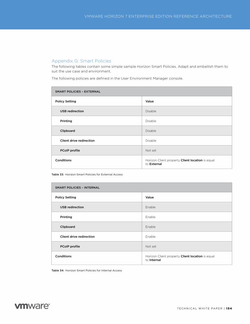
T E C H N I C A L W H I T E PA P E R | 1 3 4
VMWARE HORIZON 7 ENTERPRISE EDITION REFERENCE ARCHITECTURE
T E C H N I C A L W H I T E PA P E R | 1 3 4
Appendix G: Smart PoliciesThe following tables contain some simple sample Horizon Smart Policies . Adapt and embellish them to suit the use case and environment .
The following policies are defined in the User Environment Manager console .
SMART POLICIES – EXTERNAL
Policy Setting Value
USB redirection Disable
Printing Disable
Clipboard Disable
Client drive redirection Disable
PCoIP profile Not set
Conditions Horizon Client property Client location is equal to External
Table 33: Horizon Smart Policies for External Access
SMART POLICIES – INTERNAL
Policy Setting Value
USB redirection Enable
Printing Enable
Clipboard Enable
Client drive redirection Enable
PCoIP profile Not set
Conditions Horizon Client property Client location is equal to Internal
Table 34: Horizon Smart Policies for Internal Access
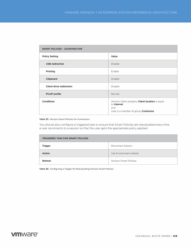
T E C H N I C A L W H I T E PA P E R | 1 3 5
VMWARE HORIZON 7 ENTERPRISE EDITION REFERENCE ARCHITECTURE
T E C H N I C A L W H I T E PA P E R | 1 3 5
SMART POLICIES – ZCONTRACTOR
Policy Setting Value
USB redirection Disable
Printing Enable
Clipboard Disable
Client drive redirection Disable
PCoIP profile Not set
Conditions Horizon Client property Client location is equal to InternalandUser is a member of group Contractor
Table 35: Horizon Smart Policies for Contractors
You should also configure a triggered task to ensure that Smart Policies are reevaluated every time a user reconnects to a session so that the user gets the appropriate policy applied .
TRIGGERED TASK FOR SMART POLICIES
Trigger Reconnect Session
Action Use Environment refresh
Refresh Horizon Smart Policies
Table 36: Configuring a Trigger for Reevaluating Horizon Smart Policies
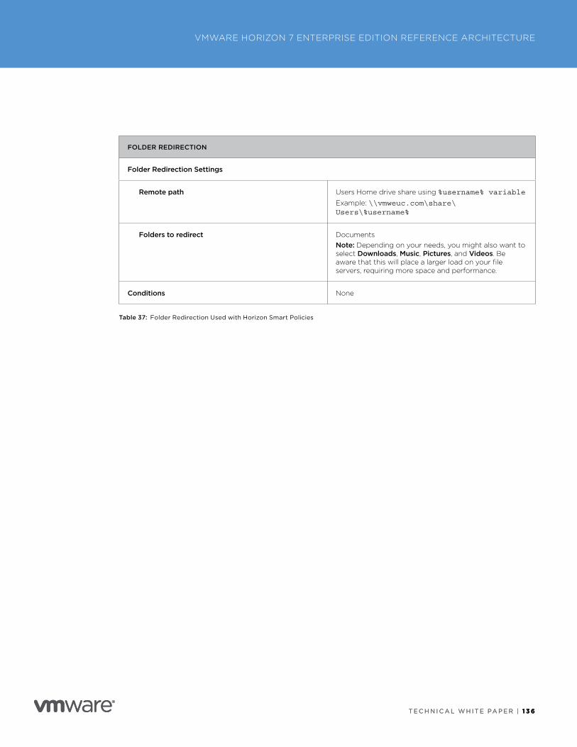
T E C H N I C A L W H I T E PA P E R | 1 3 6
VMWARE HORIZON 7 ENTERPRISE EDITION REFERENCE ARCHITECTURE
T E C H N I C A L W H I T E PA P E R | 1 3 6
FOLDER REDIRECTION
Folder Redirection Settings
Remote path Users Home drive share using %username% variable
Example: \\vmweuc.com\share\Users\%username%
Folders to redirect DocumentsNote: Depending on your needs, you might also want to select Downloads, Music, Pictures, and Videos . Be aware that this will place a larger load on your file servers, requiring more space and performance .
Conditions None
Table 37: Folder Redirection Used with Horizon Smart Policies
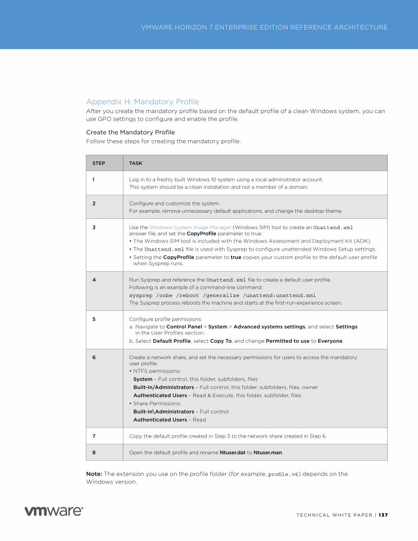
T E C H N I C A L W H I T E PA P E R | 1 3 7
VMWARE HORIZON 7 ENTERPRISE EDITION REFERENCE ARCHITECTURE
T E C H N I C A L W H I T E PA P E R | 1 3 7
Appendix H: Mandatory ProfileAfter you create the mandatory profile based on the default profile of a clean Windows system, you can use GPO settings to configure and enable the profile .
Create the Mandatory ProfileFollow these steps for creating the mandatory profile .
STEP TASK
1 Log in to a freshly built Windows 10 system using a local administrator account .This system should be a clean installation and not a member of a domain .
2 Configure and customize the system .For example, remove unnecessary default applications, and change the desktop theme .
3 Use the Windows System Image Manager (Windows SIM) tool to create an Unattend.xml answer file, and set the CopyProfile parameter to true .• The Windows SIM tool is included with the Windows Assessment and Deployment Kit (ADK) .
• The Unattend.xml file is used with Sysprep to configure unattended Windows Setup settings .
• Setting the CopyProfile parameter to true copies your custom profile to the default user profile when Sysprep runs .
4 Run Sysprep and reference the Unattend.xml file to create a default user profile . Following is an example of a command-line command:
sysprep /oobe /reboot /generalize /unattend:unattend.xml
The Sysprep process reboots the machine and starts at the first-run-experience screen .
5 Configure profile permissions:a . Navigate to Control Panel > System > Advanced systems settings, and select Settings
in the User Profiles section .
b . Select Default Profile, select Copy To, and change Permitted to use to Everyone .
6 Create a network share, and set the necessary permissions for users to access the mandatory user profile .• NTFS permissions:
System – Full control, this folder, subfolders, files
Built-in/Administrators – Full control, this folder, subfolders, files, owner
Authenticated Users – Read & Execute, this folder, subfolder, files
• Share Permissions:
Built-in\Administrators – Full control
Authenticated Users – Read
7 Copy the default profile created in Step 5 to the network share created in Step 6 .
8 Open the default profile and rename Ntuser.dat to Ntuser.man .
Note: The extension you use on the profile folder (for example, profile.v6) depends on the Windows version .
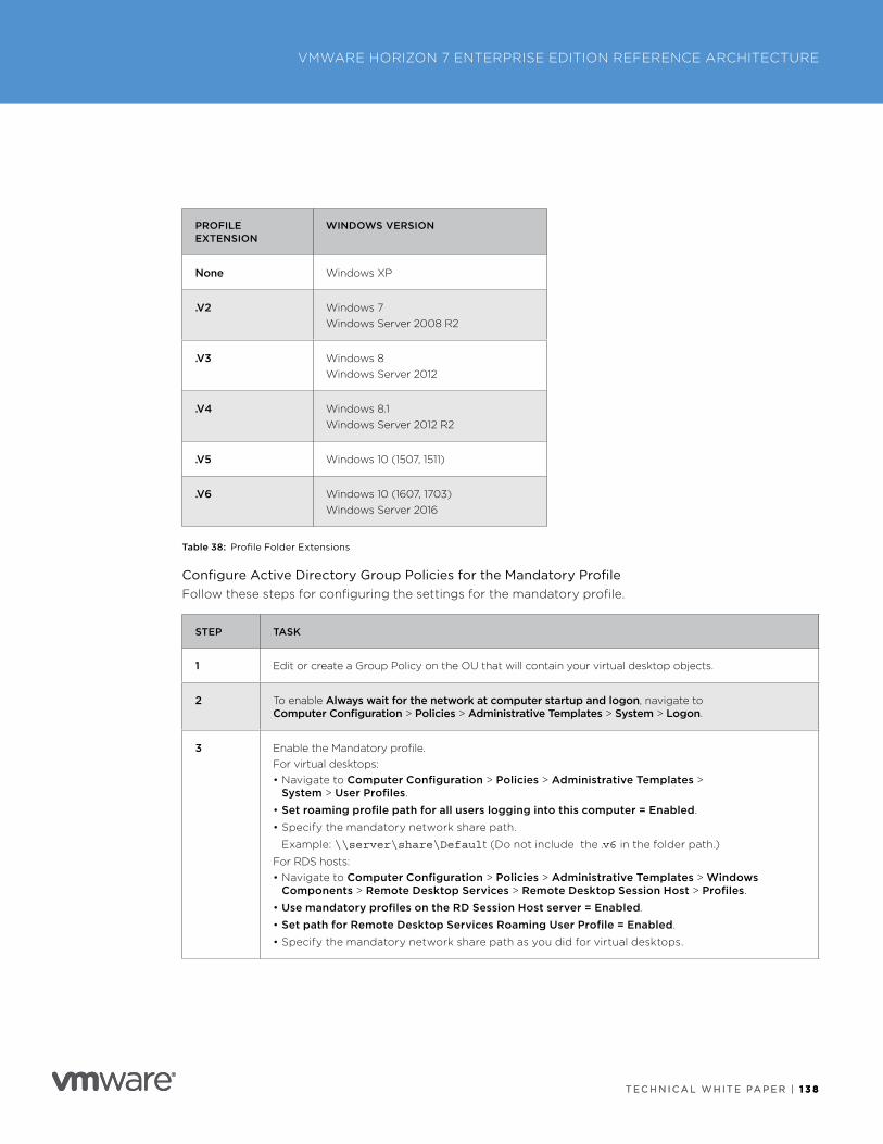
T E C H N I C A L W H I T E PA P E R | 1 3 8
VMWARE HORIZON 7 ENTERPRISE EDITION REFERENCE ARCHITECTURE
T E C H N I C A L W H I T E PA P E R | 1 3 8
PROFILE EXTENSION
WINDOWS VERSION
None Windows XP
.V2 Windows 7Windows Server 2008 R2
.V3 Windows 8Windows Server 2012
.V4 Windows 8 .1Windows Server 2012 R2
.V5 Windows 10 (1507, 1511)
.V6 Windows 10 (1607, 1703)Windows Server 2016
Table 38: Profile Folder Extensions
Configure Active Directory Group Policies for the Mandatory ProfileFollow these steps for configuring the settings for the mandatory profile .
STEP TASK
1 Edit or create a Group Policy on the OU that will contain your virtual desktop objects .
2 To enable Always wait for the network at computer startup and logon, navigate to Computer Configuration > Policies > Administrative Templates > System > Logon .
3 Enable the Mandatory profile .For virtual desktops:• Navigate to Computer Configuration > Policies > Administrative Templates >
System > User Profiles .
• Set roaming profile path for all users logging into this computer = Enabled .
• Specify the mandatory network share path .
Example: \\server\share\Default (Do not include the .v6 in the folder path .)
For RDS hosts:• Navigate to Computer Configuration > Policies > Administrative Templates > Windows
Components > Remote Desktop Services > Remote Desktop Session Host > Profiles .
• Use mandatory profiles on the RD Session Host server = Enabled .
• Set path for Remote Desktop Services Roaming User Profile = Enabled .
• Specify the mandatory network share path as you did for virtual desktops .
T E C H N I C A L W H I T E PA P E R | 1 3 9
VMWARE HORIZON 7 ENTERPRISE EDITION REFERENCE ARCHITECTURE
T E C H N I C A L W H I T E PA P E R | 1 3 9
For detailed instructions, see the following Microsoft articles:
• Configuring Standard User Accounts
• Creating a Mandatory User Profile
• Create Mandatory User Profiles
• Remove-AppxProvisionedPackage
When using mandatory profiles, also use folder redirection, which you can configure in the User Environment Manager policy .
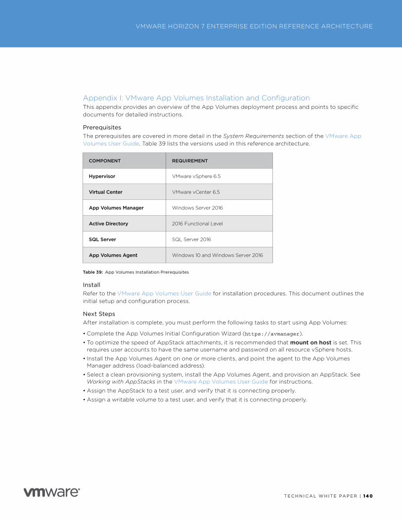
T E C H N I C A L W H I T E PA P E R | 1 4 0
VMWARE HORIZON 7 ENTERPRISE EDITION REFERENCE ARCHITECTURE
T E C H N I C A L W H I T E PA P E R | 1 4 0
Appendix I: VMware App Volumes Installation and ConfigurationThis appendix provides an overview of the App Volumes deployment process and points to specific documents for detailed instructions .
PrerequisitesThe prerequisites are covered in more detail in the System Requirements section of the VMware App Volumes User Guide . Table 39 lists the versions used in this reference architecture .
COMPONENT REQUIREMENT
Hypervisor VMware vSphere 6 .5
Virtual Center VMware vCenter 6 .5
App Volumes Manager Windows Server 2016
Active Directory 2016 Functional Level
SQL Server SQL Server 2016
App Volumes Agent Windows 10 and Windows Server 2016
Table 39: App Volumes Installation Prerequisites
InstallRefer to the VMware App Volumes User Guide for installation procedures . This document outlines the initial setup and configuration process .
Next StepsAfter installation is complete, you must perform the following tasks to start using App Volumes:
• Complete the App Volumes Initial Configuration Wizard (https://avmanager) .
• To optimize the speed of AppStack attachments, it is recommended that mount on host is set . This requires user accounts to have the same username and password on all resource vSphere hosts .
• Install the App Volumes Agent on one or more clients, and point the agent to the App Volumes Manager address (load-balanced address) .
• Select a clean provisioning system, install the App Volumes Agent, and provision an AppStack . See Working with AppStacks in the VMware App Volumes User Guide for instructions .
• Assign the AppStack to a test user, and verify that it is connecting properly .
• Assign a writable volume to a test user, and verify that it is connecting properly .
T E C H N I C A L W H I T E PA P E R | 1 4 1
VMWARE HORIZON 7 ENTERPRISE EDITION REFERENCE ARCHITECTURE
T E C H N I C A L W H I T E PA P E R | 1 4 1
Appendix J: PrintingThe virtual printing feature allows end users to use local or network printers from a Horizon 7 desktop or RDS session without requiring that additional print drivers be installed in the Horizon 7 desktop or RDS host . For each printer available through this feature, you can set preferences for data compression, print quality, double-sided printing, color, and so on .
The virtual printing feature allows Horizon Client users to transparently use local or network printers from within their remote client systems, yet removes the requirement for installing proprietary printer drivers on each Horizon 7–managed virtual desktop .
USB Redirection and PrintingTo send print jobs to a USB printer, users can use USB redirection . In a Horizon 7 environment, virtual printers and redirected USB printers can work together without conflict . A USB printer is a printer that is attached to a USB port on the local client system .
You can use USB redirection to attach a USB printer to a virtual USB port in the Horizon 7 desktop or RDS session as long as the required driver is also installed on the Horizon 7 desktop .
If you use USB redirection, the printer is no longer attached to the physical USB port on the client . This is why the USB printer does not appear in the list of local printers that the virtual printing feature displays . This also means that you can print to the USB printer from the Horizon 7 desktop or RDS session, but not from the local client machine .
On Windows clients, you can alternatively use virtual printing to send print jobs to a USB printer . If you use virtual printing, you can print to the USB printer from both the Horizon 7 desktop and the local client, and you do not need to install print drivers on the Horizon 7 desktop or RDS host .
Location-Based Printing OverviewLocation-based printing capabilities with Horizon 7 allow IT organizations to map Horizon 7 desktops to the printer that is closest to the endpoint client device .
For example, as a doctor moves from room to room in a hospital, each time the doctor prints a document, the print job is sent to the nearest printer . For sites that do not want to use virtual printing, a GPO setting can be applied through the Horizon Client group policy template, or through virtual channel or Windows Service management through GPO .
Location-based printing allows virtual desktops to be automatically mapped to network printers based on rules specified in the ThinPrint component TPVMGPoACmap.dll that appears as a Group Policy local computer setting when registered . The ThinPrint GPO rules apply one printer per rule . If multiple printers are to be mapped to the same set of virtual desktops, then multiple rules are required .
The ThinPrint AutoConnect component included with VMware Tools rebuilds the virtual desktop’s printer list based on these rules at login or reconnect from a disconnected Horizon 7 session .
The printer-mapping component can map printers to virtual desktops based on the following rules:
• Client access device IP address range
• Client access device name
• Client access device MAC address
• Active Directory user name of logged-in user
• Active Directory group membership of the logged-in user
If this feature is used, VMware recommends using the IP address range of the client access device to map local network printers to the virtual desktops .
T E C H N I C A L W H I T E PA P E R | 1 4 2
VMWARE HORIZON 7 ENTERPRISE EDITION REFERENCE ARCHITECTURE
T E C H N I C A L W H I T E PA P E R | 1 4 2
Printing EnvironmentThe following provides a high-level overview of how printing is typically used in an environment:
• Network printing – At the main campus and remote offices, users connect to a dedicated print server configured with printer shares . Users can select their printer from a portal-based map or configure printers through Active Directory (printers are filtered based on Active Directory sites or services) .
• Direct IP printing – There are use cases where printer connections are made directly to the IP address of the printer, bypassing the network printing shares on file servers or centrally managed print servers .
• Local printers – Users might also have a locally attached printer to their current endpoint or PC . These connections are typically USB connections to the endpoint . Other types of printer connections are unknown .
Design Decision: To provide a unified approach for installing and managing printers in the virtual desktops, User Environment Manager was used to map printers to users .
For remote or untrusted devices using Horizon 7 Windows-based clients, printers are automatically brought into the virtual desktop using ThinPrint virtual printing technologies . No drivers need to be installed on the local Windows endpoint . Other thin clients, zero clients, or mobile devices use the printer map to select their on-premises printer .
Non-Windows devices that do not use ThinPrint and have local printers attached to them can use USB redirection for printing, if necessary .
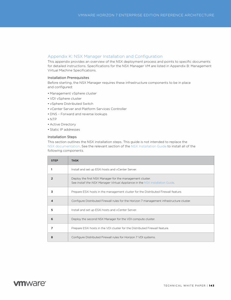
T E C H N I C A L W H I T E PA P E R | 1 4 3
VMWARE HORIZON 7 ENTERPRISE EDITION REFERENCE ARCHITECTURE
T E C H N I C A L W H I T E PA P E R | 1 4 3
Appendix K: NSX Manager Installation and ConfigurationThis appendix provides an overview of the NSX deployment process and points to specific documents for detailed instructions . Specifications for the NSX Manager VM are listed in Appendix B: Management Virtual Machine Specifications .
Installation PrerequisitesBefore starting, the NSX Manager requires these infrastructure components to be in place and configured:
• Management vSphere cluster
• VDI vSphere cluster
• vSphere Distributed Switch
• vCenter Server and Platform Services Controller
• DNS – Forward and reverse lookups
• NTP
• Active Directory
• Static IP addresses
Installation StepsThis section outlines the NSX installation steps . This guide is not intended to replace the NSX documentation . See the relevant section of the NSX Installation Guide to install all of the following components .
STEP TASK
1 Install and set up ESXi hosts and vCenter Server .
2 Deploy the first NSX Manager for the management cluster .See Install the NSX Manager Virtual Appliance in the NSX Installation Guide .
3 Prepare ESXi hosts in the management cluster for the Distributed Firewall feature .
4 Configure Distributed Firewall rules for the Horizon 7 management infrastructure cluster .
5 Install and set up ESXi hosts and vCenter Server .
6 Deploy the second NSX Manager for the VDI compute cluster .
7 Prepare ESXi hosts in the VDI cluster for the Distributed Firewall feature .
8 Configure Distributed Firewall rules for Horizon 7 VDI systems .
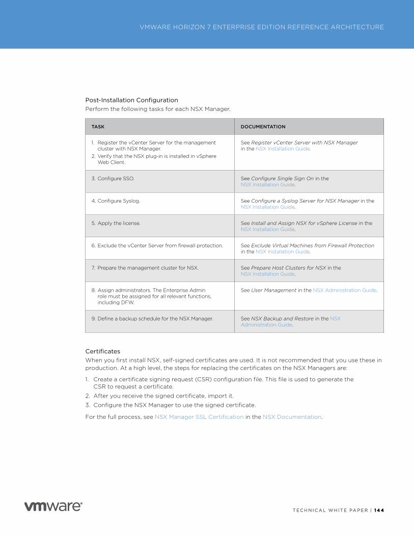
T E C H N I C A L W H I T E PA P E R | 1 4 4
VMWARE HORIZON 7 ENTERPRISE EDITION REFERENCE ARCHITECTURE
T E C H N I C A L W H I T E PA P E R | 1 4 4
Post-Installation ConfigurationPerform the following tasks for each NSX Manager .
TASK DOCUMENTATION
1 . Register the vCenter Server for the management cluster with NSX Manager .
2 . Verify that the NSX plug-in is installed in vSphere Web Client .
See Register vCenter Server with NSX Manager in the NSX Installation Guide .
3 . Configure SSO . See Configure Single Sign On in the NSX Installation Guide .
4 . Configure Syslog . See Configure a Syslog Server for NSX Manager in the NSX Installation Guide .
5 . Apply the license . See Install and Assign NSX for vSphere License in the NSX Installation Guide .
6 . Exclude the vCenter Server from firewall protection . See Exclude Virtual Machines from Firewall Protection in the NSX Installation Guide .
7 . Prepare the management cluster for NSX . See Prepare Host Clusters for NSX in the NSX Installation Guide .
8 . Assign administrators . The Enterprise Admin role must be assigned for all relevant functions, including DFW .
See User Management in the NSX Administration Guide .
9 . Define a backup schedule for the NSX Manager . See NSX Backup and Restore in the NSX Administration Guide .
CertificatesWhen you first install NSX, self-signed certificates are used . It is not recommended that you use these in production . At a high level, the steps for replacing the certificates on the NSX Managers are:
1 . Create a certificate signing request (CSR) configuration file . This file is used to generate the CSR to request a certificate .
2 . After you receive the signed certificate, import it .
3 . Configure the NSX Manager to use the signed certificate .
For the full process, see NSX Manager SSL Certification in the NSX Documentation .
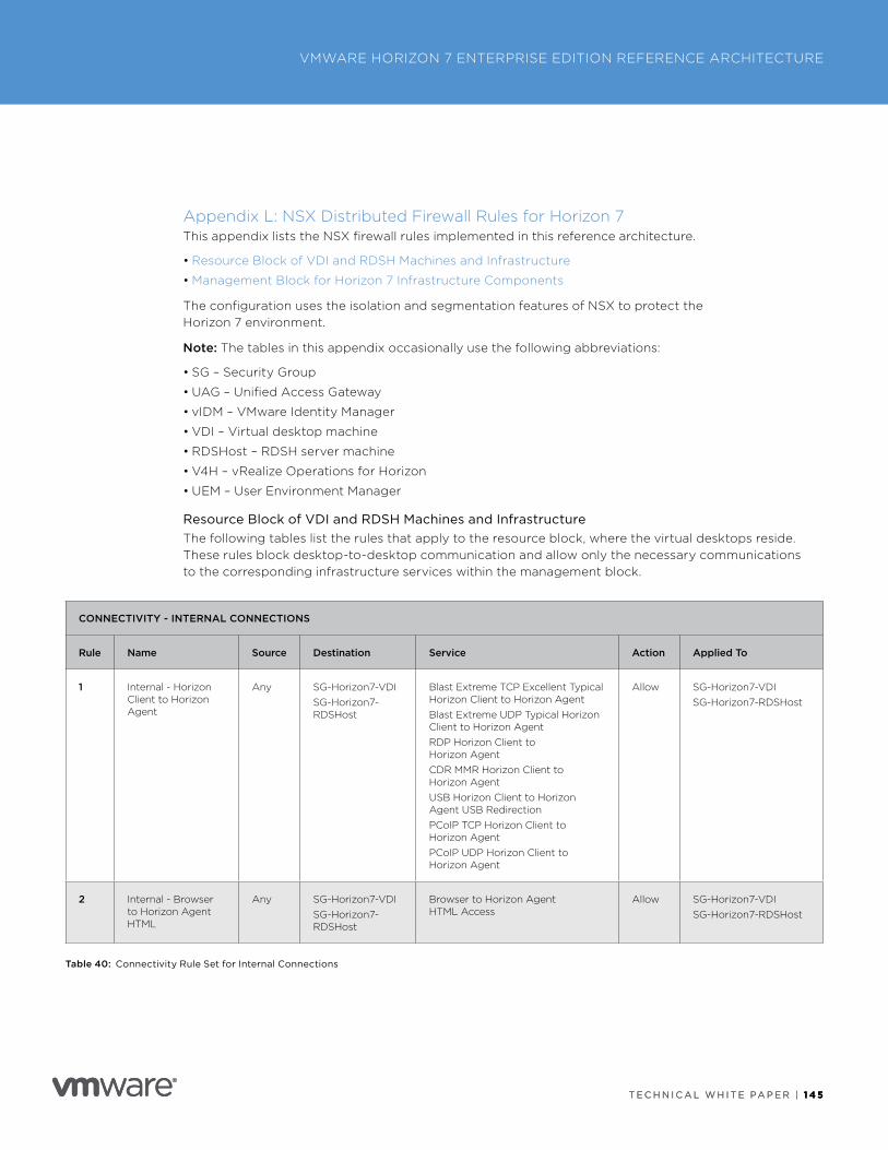
T E C H N I C A L W H I T E PA P E R | 1 4 5
VMWARE HORIZON 7 ENTERPRISE EDITION REFERENCE ARCHITECTURE
T E C H N I C A L W H I T E PA P E R | 1 4 5
Appendix L: NSX Distributed Firewall Rules for Horizon 7This appendix lists the NSX firewall rules implemented in this reference architecture .
• Resource Block of VDI and RDSH Machines and Infrastructure
• Management Block for Horizon 7 Infrastructure Components
The configuration uses the isolation and segmentation features of NSX to protect the Horizon 7 environment .
Note: The tables in this appendix occasionally use the following abbreviations:
• SG – Security Group
• UAG – Unified Access Gateway
• vIDM – VMware Identity Manager
• VDI – Virtual desktop machine
• RDSHost – RDSH server machine
• V4H – vRealize Operations for Horizon
• UEM – User Environment Manager
Resource Block of VDI and RDSH Machines and InfrastructureThe following tables list the rules that apply to the resource block, where the virtual desktops reside . These rules block desktop-to-desktop communication and allow only the necessary communications to the corresponding infrastructure services within the management block .
CONNECTIVITY - INTERNAL CONNECTIONS
Rule Name Source Destination Service Action Applied To
1 Internal - Horizon Client to Horizon Agent
Any SG-Horizon7-VDISG-Horizon7-RDSHost
Blast Extreme TCP Excellent Typical Horizon Client to Horizon AgentBlast Extreme UDP Typical Horizon Client to Horizon AgentRDP Horizon Client to Horizon AgentCDR MMR Horizon Client to Horizon AgentUSB Horizon Client to Horizon Agent USB RedirectionPCoIP TCP Horizon Client to Horizon Agent PCoIP UDP Horizon Client to Horizon Agent
Allow SG-Horizon7-VDISG-Horizon7-RDSHost
2 Internal - Browser to Horizon Agent HTML
Any SG-Horizon7-VDISG-Horizon7-RDSHost
Browser to Horizon Agent HTML Access
Allow SG-Horizon7-VDISG-Horizon7-RDSHost
Table 40: Connectivity Rule Set for Internal Connections
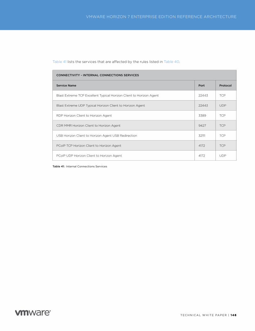
T E C H N I C A L W H I T E PA P E R | 1 4 6
VMWARE HORIZON 7 ENTERPRISE EDITION REFERENCE ARCHITECTURE
T E C H N I C A L W H I T E PA P E R | 1 4 6
Table 41 lists the services that are affected by the rules listed in Table 40 .
CONNECTIVITY - INTERNAL CONNECTIONS SERVICES
Service Name Port Protocol
Blast Extreme TCP Excellent Typical Horizon Client to Horizon Agent 22443 TCP
Blast Extreme UDP Typical Horizon Client to Horizon Agent 22443 UDP
RDP Horizon Client to Horizon Agent 3389 TCP
CDR MMR Horizon Client to Horizon Agent 9427 TCP
USB Horizon Client to Horizon Agent USB Redirection 32111 TCP
PCoIP TCP Horizon Client to Horizon Agent 4172 TCP
PCoIP UDP Horizon Client to Horizon Agent 4172 UDP
Table 41: Internal Connections Services
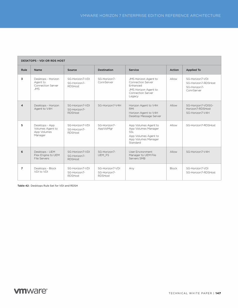
T E C H N I C A L W H I T E PA P E R | 1 47
VMWARE HORIZON 7 ENTERPRISE EDITION REFERENCE ARCHITECTURE
T E C H N I C A L W H I T E PA P E R | 1 47
DESKTOPS - VDI OR RDS HOST
Rule Name Source Destination Service Action Applied To
3 Desktops - Horizon Agent to Connection Server JMS
SG-Horizon7-VDISG-Horizon7-RDSHost
SG-Horizon7-ConnServer
JMS Horizon Agent to Connection Server EnhancedJMS Horizon Agent to Connection Server Legacy
Allow SG-Horizon7-VDISG-Horizon7-RDSHostSG-Horizon7-ConnServer
4 Desktops - Horizon Agent to V4H
SG-Horizon7-VDISG-Horizon7-RDSHost
SG-Horizon7-V4H Horizon Agent to V4H RMIHorizon Agent to V4H Desktop Message Server
Allow SG-Horizon7-VDISG-Horizon7-RDSHostSG-Horizon7-V4H
5 Desktops - App Volumes Agent to App Volumes Manager
SG-Horizon7-VDISG-Horizon7-RDSHost
SG-Horizon7-AppVolMgr
App Volumes Agent to App Volumes Manager SSLApp Volumes Agent to App Volumes Manager Standard
Allow SG-Horizon7-RDSHost
6 Desktops - UEM Flex Engine to UEM File Servers
SG-Horizon7-VDISG-Horizon7-RDSHost
SG-Horizon7-UEM_FS
User Environment Manager to UEM File Servers SMB
Allow SG-Horizon7-V4H
7 Desktops - Block VDI to VDI
SG-Horizon7-VDISG-Horizon7-RDSHost
SG-Horizon7-VDISG-Horizon7-RDSHost
Any Block SG-Horizon7-VDISG-Horizon7-RDSHost
Table 42: Desktops Rule Set for VDI and RDSH
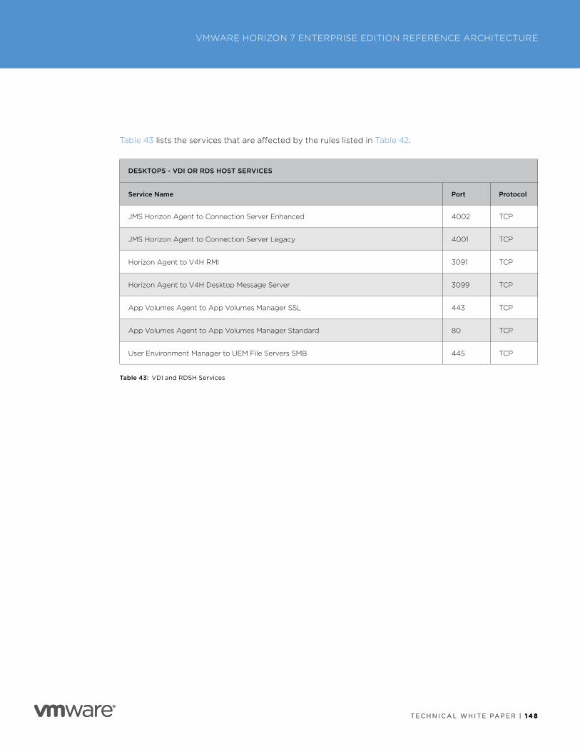
T E C H N I C A L W H I T E PA P E R | 1 4 8
VMWARE HORIZON 7 ENTERPRISE EDITION REFERENCE ARCHITECTURE
T E C H N I C A L W H I T E PA P E R | 1 4 8
Table 43 lists the services that are affected by the rules listed in Table 42 .
DESKTOPS - VDI OR RDS HOST SERVICES
Service Name Port Protocol
JMS Horizon Agent to Connection Server Enhanced 4002 TCP
JMS Horizon Agent to Connection Server Legacy 4001 TCP
Horizon Agent to V4H RMI 3091 TCP
Horizon Agent to V4H Desktop Message Server 3099 TCP
App Volumes Agent to App Volumes Manager SSL 443 TCP
App Volumes Agent to App Volumes Manager Standard 80 TCP
User Environment Manager to UEM File Servers SMB 445 TCP
Table 43: VDI and RDSH Services
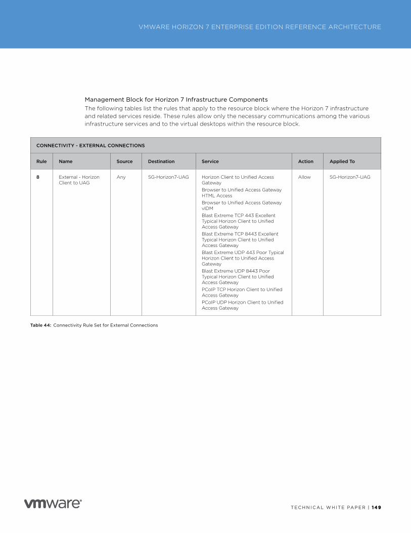
T E C H N I C A L W H I T E PA P E R | 1 4 9
VMWARE HORIZON 7 ENTERPRISE EDITION REFERENCE ARCHITECTURE
T E C H N I C A L W H I T E PA P E R | 1 4 9
Management Block for Horizon 7 Infrastructure ComponentsThe following tables list the rules that apply to the resource block where the Horizon 7 infrastructure and related services reside . These rules allow only the necessary communications among the various infrastructure services and to the virtual desktops within the resource block .
CONNECTIVITY - EXTERNAL CONNECTIONS
Rule Name Source Destination Service Action Applied To
8 External - Horizon Client to UAG
Any SG-Horizon7-UAG Horizon Client to Unified Access GatewayBrowser to Unified Access Gateway HTML AccessBrowser to Unified Access Gateway vIDMBlast Extreme TCP 443 Excellent Typical Horizon Client to Unified Access GatewayBlast Extreme TCP 8443 Excellent Typical Horizon Client to Unified Access GatewayBlast Extreme UDP 443 Poor Typical Horizon Client to Unified Access GatewayBlast Extreme UDP 8443 Poor Typical Horizon Client to Unified Access GatewayPCoIP TCP Horizon Client to Unified Access GatewayPCoIP UDP Horizon Client to Unified Access Gateway
Allow SG-Horizon7-UAG
Table 44: Connectivity Rule Set for External Connections
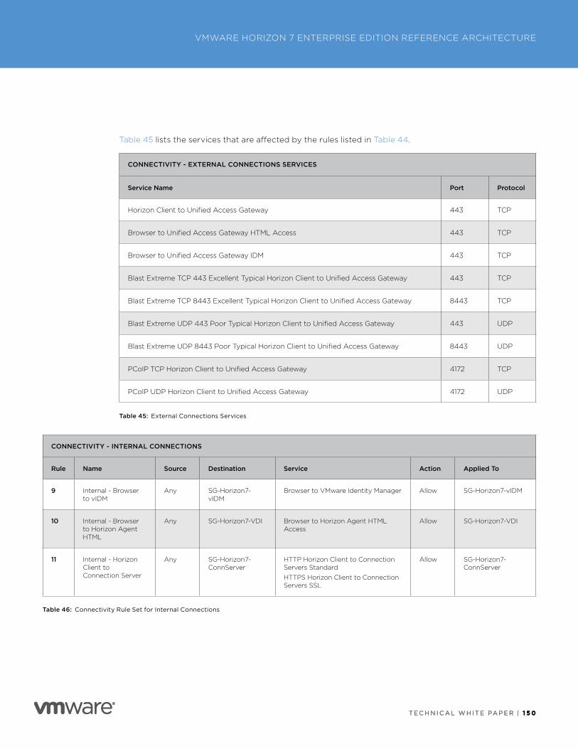
T E C H N I C A L W H I T E PA P E R | 1 5 0
VMWARE HORIZON 7 ENTERPRISE EDITION REFERENCE ARCHITECTURE
T E C H N I C A L W H I T E PA P E R | 1 5 0
Table 45 lists the services that are affected by the rules listed in Table 44 .
CONNECTIVITY - EXTERNAL CONNECTIONS SERVICES
Service Name Port Protocol
Horizon Client to Unified Access Gateway 443 TCP
Browser to Unified Access Gateway HTML Access 443 TCP
Browser to Unified Access Gateway IDM 443 TCP
Blast Extreme TCP 443 Excellent Typical Horizon Client to Unified Access Gateway 443 TCP
Blast Extreme TCP 8443 Excellent Typical Horizon Client to Unified Access Gateway 8443 TCP
Blast Extreme UDP 443 Poor Typical Horizon Client to Unified Access Gateway 443 UDP
Blast Extreme UDP 8443 Poor Typical Horizon Client to Unified Access Gateway 8443 UDP
PCoIP TCP Horizon Client to Unified Access Gateway 4172 TCP
PCoIP UDP Horizon Client to Unified Access Gateway 4172 UDP
Table 45: External Connections Services
CONNECTIVITY - INTERNAL CONNECTIONS
Rule Name Source Destination Service Action Applied To
9 Internal - Browser to vIDM
Any SG-Horizon7-vIDM
Browser to VMware Identity Manager Allow SG-Horizon7-vIDM
10 Internal - Browser to Horizon Agent HTML
Any SG-Horizon7-VDI Browser to Horizon Agent HTML Access
Allow SG-Horizon7-VDI
11 Internal - Horizon Client to Connection Server
Any SG-Horizon7-ConnServer
HTTP Horizon Client to Connection Servers StandardHTTPS Horizon Client to Connection Servers SSL
Allow SG-Horizon7-ConnServer
Table 46: Connectivity Rule Set for Internal Connections
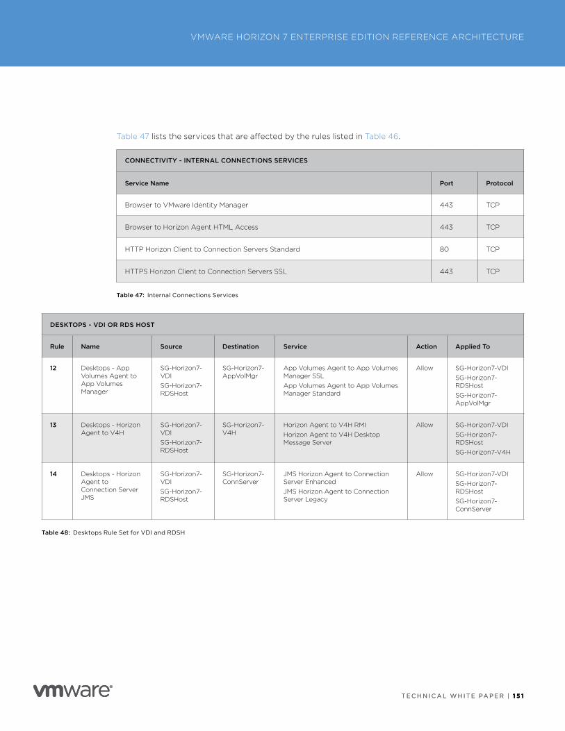
T E C H N I C A L W H I T E PA P E R | 1 5 1
VMWARE HORIZON 7 ENTERPRISE EDITION REFERENCE ARCHITECTURE
T E C H N I C A L W H I T E PA P E R | 1 5 1
Table 47 lists the services that are affected by the rules listed in Table 46 .
CONNECTIVITY - INTERNAL CONNECTIONS SERVICES
Service Name Port Protocol
Browser to VMware Identity Manager 443 TCP
Browser to Horizon Agent HTML Access 443 TCP
HTTP Horizon Client to Connection Servers Standard 80 TCP
HTTPS Horizon Client to Connection Servers SSL 443 TCP
Table 47: Internal Connections Services
DESKTOPS - VDI OR RDS HOST
Rule Name Source Destination Service Action Applied To
12 Desktops - App Volumes Agent to App Volumes Manager
SG-Horizon7-VDISG-Horizon7-RDSHost
SG-Horizon7-AppVolMgr
App Volumes Agent to App Volumes Manager SSLApp Volumes Agent to App Volumes Manager Standard
Allow SG-Horizon7-VDISG-Horizon7-RDSHostSG-Horizon7-AppVolMgr
13 Desktops - Horizon Agent to V4H
SG-Horizon7-VDISG-Horizon7-RDSHost
SG-Horizon7-V4H
Horizon Agent to V4H RMIHorizon Agent to V4H Desktop Message Server
Allow SG-Horizon7-VDISG-Horizon7-RDSHostSG-Horizon7-V4H
14 Desktops - Horizon Agent to Connection Server JMS
SG-Horizon7-VDISG-Horizon7-RDSHost
SG-Horizon7-ConnServer
JMS Horizon Agent to Connection Server EnhancedJMS Horizon Agent to Connection Server Legacy
Allow SG-Horizon7-VDISG-Horizon7-RDSHostSG-Horizon7-ConnServer
Table 48: Desktops Rule Set for VDI and RDSH
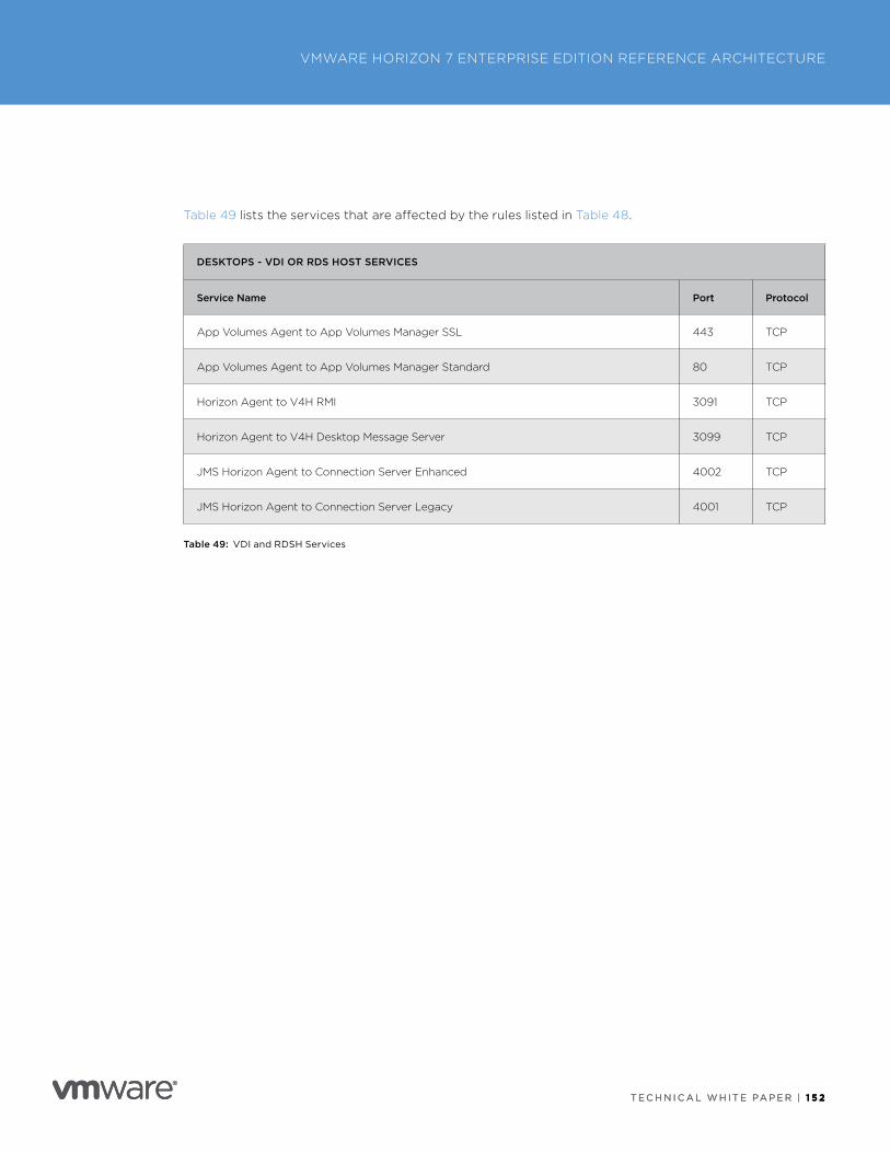
T E C H N I C A L W H I T E PA P E R | 1 5 2
VMWARE HORIZON 7 ENTERPRISE EDITION REFERENCE ARCHITECTURE
T E C H N I C A L W H I T E PA P E R | 1 5 2
Table 49 lists the services that are affected by the rules listed in Table 48 .
DESKTOPS - VDI OR RDS HOST SERVICES
Service Name Port Protocol
App Volumes Agent to App Volumes Manager SSL 443 TCP
App Volumes Agent to App Volumes Manager Standard 80 TCP
Horizon Agent to V4H RMI 3091 TCP
Horizon Agent to V4H Desktop Message Server 3099 TCP
JMS Horizon Agent to Connection Server Enhanced 4002 TCP
JMS Horizon Agent to Connection Server Legacy 4001 TCP
Table 49: VDI and RDSH Services
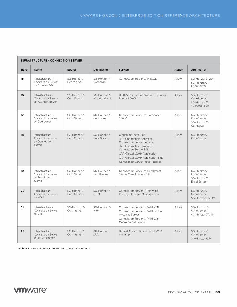
T E C H N I C A L W H I T E PA P E R | 1 5 3
VMWARE HORIZON 7 ENTERPRISE EDITION REFERENCE ARCHITECTURE
T E C H N I C A L W H I T E PA P E R | 1 5 3
INFRASTRUCTURE - CONNECTION SERVER
Rule Name Source Destination Service Action Applied To
15 Infrastructure - Connection Server to External DB
SG-Horizon7-ConnServer
SG-Horizon7-Database
Connection Server to MSSQL Allow SG-Horizon7-VDISG-Horizon7-ConnServer
16 Infrastructure - Connection Server to vCenter Server
SG-Horizon7-ConnServer
SG-Horizon7-vCenterMgmt
HTTPS Connection Server to vCenter Server SOAP
Allow SG-Horizon7-ConnServerSG-Horizon7-vCenterMgmt
17 Infrastructure - Connection Server to Composer
SG-Horizon7-ConnServer
SG-Horizon7-Composer
Connection Server to Composer SOAP
Allow SG-Horizon7-ConnServerSG-Horizon7-Composer
18 Infrastructure - Connection Server to Connection Server
SG-Horizon7-ConnServer
SG-Horizon7-ConnServer
Cloud Pod Inter-PodJMS Connection Server to Connection Server LegacyJMS Connection Server to Connection Server SSLCPA Global LDAP ReplicationCPA Global LDAP Replication SSLConnection Server Install Replica
Allow SG-Horizon7-ConnServer
19 Infrastructure - Connection Server to Enrollment Server
SG-Horizon7-ConnServer
SG-Horizon7-EnrollServer
Connection Server to Enrollment Server View Framework
Allow SG-Horizon7-ConnServerSG-Horizon7-EnrollServer
20 Infrastructure - Connection Server to vIDM
SG-Horizon7-ConnServer
SG-Horizon7-vIDM
Connection Server to VMware Identity Manager Message Bus
Allow SG-Horizon7-ConnServerSG-Horizon7-vIDM
21 Infrastructure - Connection Server to V4H
SG-Horizon7-ConnServer
SG-Horizon7-V4H
Connection Server to V4H RMIConnection Server to V4H Broker Message ServerConnection Server to V4H Cert Management Server
Allow SG-Horizon7-ConnServerSG-Horizon7-V4H
22 Infrastructure - Connection Server to 2FA Manager
SG-Horizon7-ConnServer
SG-Horizon-2FA
Default Connection Server to 2FA Manager
Allow SG-Horizon7-ConnServerSG-Horizon-2FA
Table 50: Infrastructure Rule Set for Connection Servers
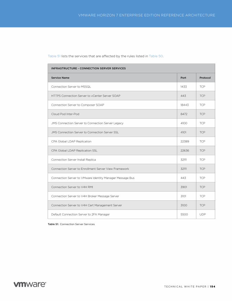
T E C H N I C A L W H I T E PA P E R | 1 5 4
VMWARE HORIZON 7 ENTERPRISE EDITION REFERENCE ARCHITECTURE
T E C H N I C A L W H I T E PA P E R | 1 5 4
Table 51 lists the services that are affected by the rules listed in Table 50 .
INFRASTRUCTURE - CONNECTION SERVER SERVICES
Service Name Port Protocol
Connection Server to MSSQL 1433 TCP
HTTPS Connection Server to vCenter Server SOAP 443 TCP
Connection Server to Composer SOAP 18443 TCP
Cloud Pod Inter-Pod 8472 TCP
JMS Connection Server to Connection Server Legacy 4100 TCP
JMS Connection Server to Connection Server SSL 4101 TCP
CPA Global LDAP Replication 22389 TCP
CPA Global LDAP Replication SSL 22636 TCP
Connection Server Install Replica 32111 TCP
Connection Server to Enrollment Server View Framework 32111 TCP
Connection Server to VMware Identity Manager Message Bus 443 TCP
Connection Server to V4H RMI 3901 TCP
Connection Server to V4H Broker Message Server 3101 TCP
Connection Server to V4H Cert Management Server 3100 TCP
Default Connection Server to 2FA Manager 5500 UDP
Table 51: Connection Server Services
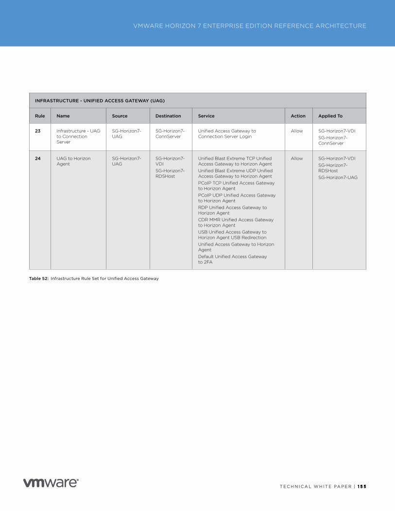
T E C H N I C A L W H I T E PA P E R | 1 5 5
VMWARE HORIZON 7 ENTERPRISE EDITION REFERENCE ARCHITECTURE
T E C H N I C A L W H I T E PA P E R | 1 5 5
INFRASTRUCTURE - UNIFIED ACCESS GATEWAY (UAG)
Rule Name Source Destination Service Action Applied To
23 Infrastructure - UAG to Connection Server
SG-Horizon7-UAG
SG-Horizon7-ConnServer
Unified Access Gateway to Connection Server Login
Allow SG-Horizon7-VDISG-Horizon7-ConnServer
24 UAG to Horizon Agent
SG-Horizon7-UAG
SG-Horizon7-VDISG-Horizon7-RDSHost
Unified Blast Extreme TCP Unified Access Gateway to Horizon AgentUnified Blast Extreme UDP Unified Access Gateway to Horizon AgentPCoIP TCP Unified Access Gateway to Horizon AgentPCoIP UDP Unified Access Gateway to Horizon AgentRDP Unified Access Gateway to Horizon AgentCDR MMR Unified Access Gateway to Horizon AgentUSB Unified Access Gateway to Horizon Agent USB RedirectionUnified Access Gateway to Horizon AgentDefault Unified Access Gateway to 2FA
Allow SG-Horizon7-VDISG-Horizon7-RDSHostSG-Horizon7-UAG
Table 52: Infrastructure Rule Set for Unified Access Gateway
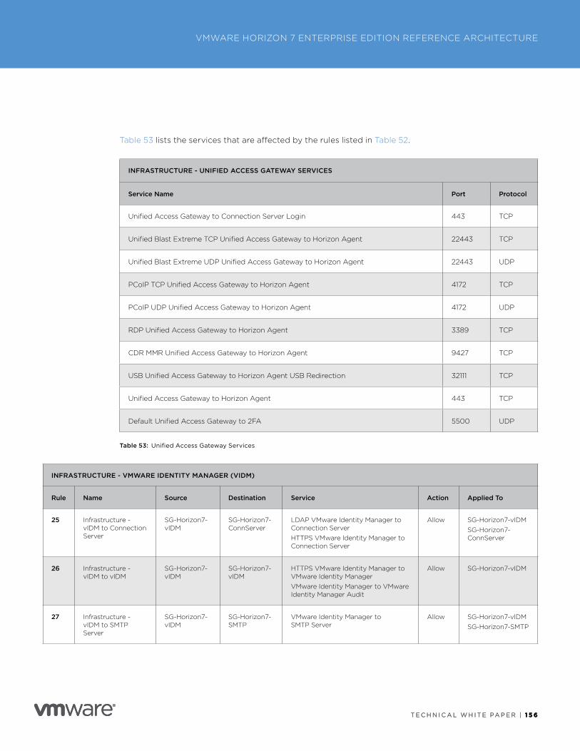
T E C H N I C A L W H I T E PA P E R | 1 5 6
VMWARE HORIZON 7 ENTERPRISE EDITION REFERENCE ARCHITECTURE
T E C H N I C A L W H I T E PA P E R | 1 5 6
Table 53 lists the services that are affected by the rules listed in Table 52 .
INFRASTRUCTURE - UNIFIED ACCESS GATEWAY SERVICES
Service Name Port Protocol
Unified Access Gateway to Connection Server Login 443 TCP
Unified Blast Extreme TCP Unified Access Gateway to Horizon Agent 22443 TCP
Unified Blast Extreme UDP Unified Access Gateway to Horizon Agent 22443 UDP
PCoIP TCP Unified Access Gateway to Horizon Agent 4172 TCP
PCoIP UDP Unified Access Gateway to Horizon Agent 4172 UDP
RDP Unified Access Gateway to Horizon Agent 3389 TCP
CDR MMR Unified Access Gateway to Horizon Agent 9427 TCP
USB Unified Access Gateway to Horizon Agent USB Redirection 32111 TCP
Unified Access Gateway to Horizon Agent 443 TCP
Default Unified Access Gateway to 2FA 5500 UDP
Table 53: Unified Access Gateway Services
INFRASTRUCTURE - VMWARE IDENTITY MANAGER (VIDM)
Rule Name Source Destination Service Action Applied To
25 Infrastructure - vIDM to Connection Server
SG-Horizon7-vIDM
SG-Horizon7-ConnServer
LDAP VMware Identity Manager to Connection ServerHTTPS VMware Identity Manager to Connection Server
Allow SG-Horizon7-vIDMSG-Horizon7-ConnServer
26 Infrastructure - vIDM to vIDM
SG-Horizon7-vIDM
SG-Horizon7-vIDM
HTTPS VMware Identity Manager to VMware Identity ManagerVMware Identity Manager to VMware Identity Manager Audit
Allow SG-Horizon7-vIDM
27 Infrastructure - vIDM to SMTP Server
SG-Horizon7-vIDM
SG-Horizon7-SMTP
VMware Identity Manager to SMTP Server
Allow SG-Horizon7-vIDMSG-Horizon7-SMTP
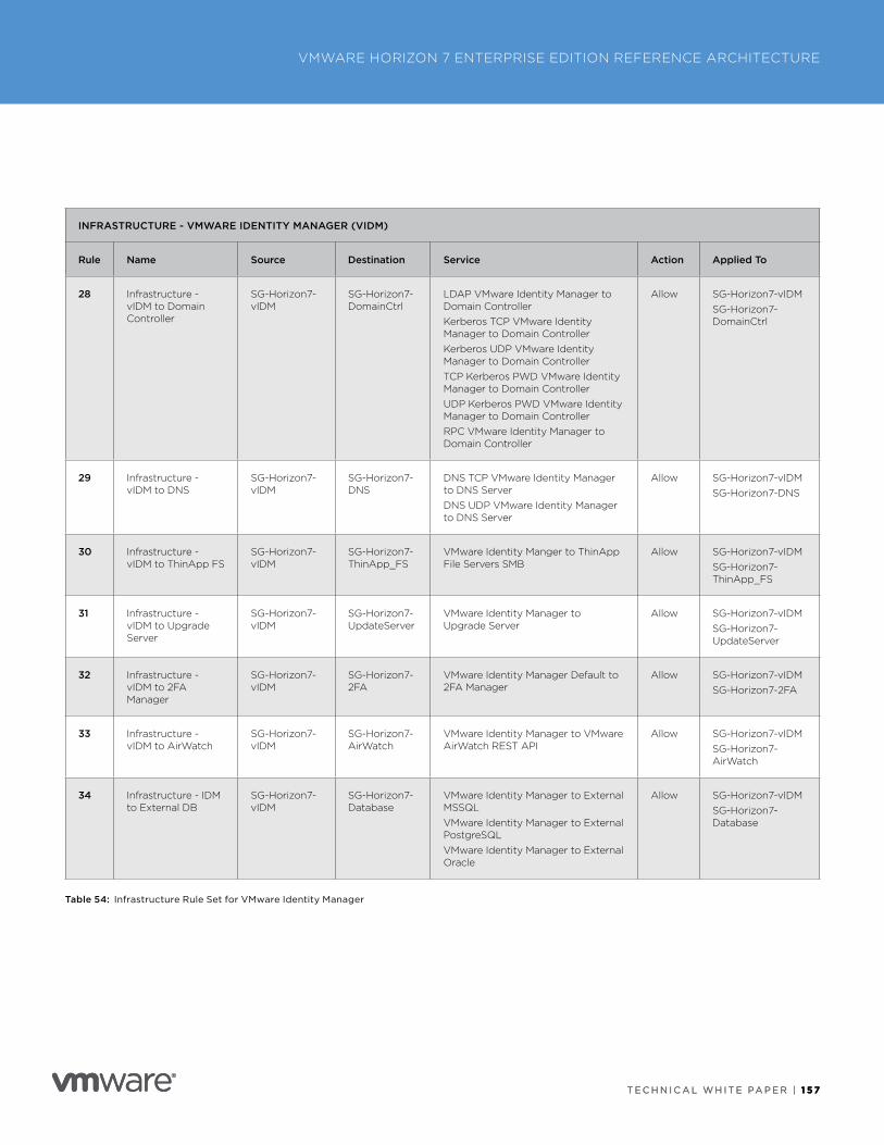
T E C H N I C A L W H I T E PA P E R | 1 5 7
VMWARE HORIZON 7 ENTERPRISE EDITION REFERENCE ARCHITECTURE
T E C H N I C A L W H I T E PA P E R | 1 5 7
INFRASTRUCTURE - VMWARE IDENTITY MANAGER (VIDM)
Rule Name Source Destination Service Action Applied To
28 Infrastructure - vIDM to Domain Controller
SG-Horizon7-vIDM
SG-Horizon7-DomainCtrl
LDAP VMware Identity Manager to Domain ControllerKerberos TCP VMware Identity Manager to Domain ControllerKerberos UDP VMware Identity Manager to Domain ControllerTCP Kerberos PWD VMware Identity Manager to Domain ControllerUDP Kerberos PWD VMware Identity Manager to Domain ControllerRPC VMware Identity Manager to Domain Controller
Allow SG-Horizon7-vIDMSG-Horizon7-DomainCtrl
29 Infrastructure - vIDM to DNS
SG-Horizon7-vIDM
SG-Horizon7-DNS
DNS TCP VMware Identity Manager to DNS ServerDNS UDP VMware Identity Manager to DNS Server
Allow SG-Horizon7-vIDMSG-Horizon7-DNS
30 Infrastructure - vIDM to ThinApp FS
SG-Horizon7-vIDM
SG-Horizon7-ThinApp_FS
VMware Identity Manger to ThinApp File Servers SMB
Allow SG-Horizon7-vIDMSG-Horizon7-ThinApp_FS
31 Infrastructure - vIDM to Upgrade Server
SG-Horizon7-vIDM
SG-Horizon7-UpdateServer
VMware Identity Manager to Upgrade Server
Allow SG-Horizon7-vIDMSG-Horizon7-UpdateServer
32 Infrastructure - vIDM to 2FA Manager
SG-Horizon7-vIDM
SG-Horizon7-2FA
VMware Identity Manager Default to 2FA Manager
Allow SG-Horizon7-vIDMSG-Horizon7-2FA
33 Infrastructure - vIDM to AirWatch
SG-Horizon7-vIDM
SG-Horizon7-AirWatch
VMware Identity Manager to VMware AirWatch REST API
Allow SG-Horizon7-vIDMSG-Horizon7-AirWatch
34 Infrastructure - IDM to External DB
SG-Horizon7-vIDM
SG-Horizon7-Database
VMware Identity Manager to External MSSQLVMware Identity Manager to External PostgreSQLVMware Identity Manager to External Oracle
Allow SG-Horizon7-vIDMSG-Horizon7-Database
Table 54: Infrastructure Rule Set for VMware Identity Manager
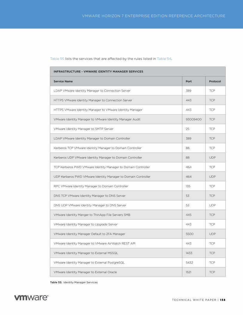
T E C H N I C A L W H I T E PA P E R | 1 5 8
VMWARE HORIZON 7 ENTERPRISE EDITION REFERENCE ARCHITECTURE
T E C H N I C A L W H I T E PA P E R | 1 5 8
Table 55 lists the services that are affected by the rules listed in Table 54 .
INFRASTRUCTURE - VMWARE IDENTITY MANAGER SERVICES
Service Name Port Protocol
LDAP VMware Identity Manager to Connection Server 389 TCP
HTTPS VMware Identity Manager to Connection Server 443 TCP
HTTPS VMware Identity Manager to VMware Identity Manager 443 TCP
VMware Identity Manager to VMware Identity Manager Audit 93009400 TCP
VMware Identity Manager to SMTP Server 25 TCP
LDAP VMware Identity Manager to Domain Controller 389 TCP
Kerberos TCP VMware Identity Manager to Domain Controller 88 TCP
Kerberos UDP VMware Identity Manager to Domain Controller 88 UDP
TCP Kerberos PWD VMware Identity Manager to Domain Controller 464 TCP
UDP Kerberos PWD VMware Identity Manager to Domain Controller 464 UDP
RPC VMware Identity Manager to Domain Controller 135 TCP
DNS TCP VMware Identity Manager to DNS Server 53 TCP
DNS UDP VMware Identity Manager to DNS Server 53 UDP
VMware Identity Manger to ThinApp File Servers SMB 445 TCP
VMware Identity Manager to Upgrade Server 443 TCP
VMware Identity Manager Default to 2FA Manager 5500 UDP
VMware Identity Manager to VMware AirWatch REST API 443 TCP
VMware Identity Manager to External MSSQL 1433 TCP
VMware Identity Manager to External PostgreSQL 5432 TCP
VMware Identity Manager to External Oracle 1521 TCP
Table 55: Identity Manager Services
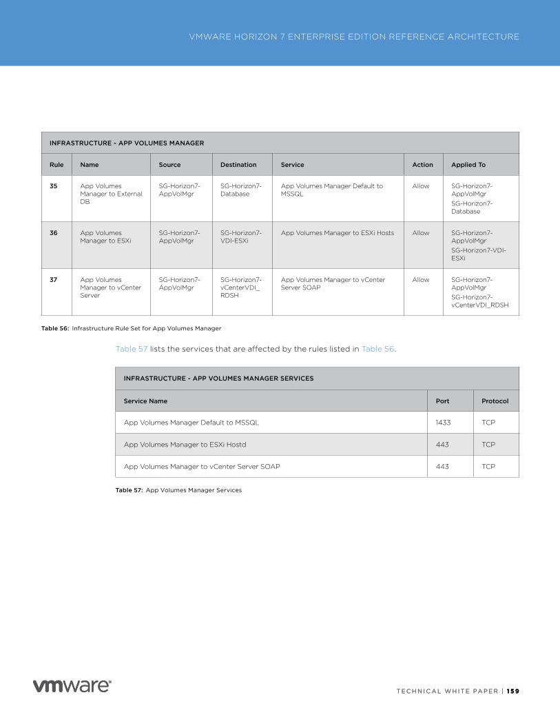
T E C H N I C A L W H I T E PA P E R | 1 5 9
VMWARE HORIZON 7 ENTERPRISE EDITION REFERENCE ARCHITECTURE
T E C H N I C A L W H I T E PA P E R | 1 5 9
INFRASTRUCTURE - APP VOLUMES MANAGER
Rule Name Source Destination Service Action Applied To
35 App Volumes Manager to External DB
SG-Horizon7-AppVolMgr
SG-Horizon7-Database
App Volumes Manager Default to MSSQL
Allow SG-Horizon7-AppVolMgrSG-Horizon7-Database
36 App Volumes Manager to ESXi
SG-Horizon7-AppVolMgr
SG-Horizon7-VDI-ESXi
App Volumes Manager to ESXi Hosts Allow SG-Horizon7-AppVolMgrSG-Horizon7-VDI-ESXi
37 App Volumes Manager to vCenter Server
SG-Horizon7-AppVolMgr
SG-Horizon7-vCenterVDI_RDSH
App Volumes Manager to vCenter Server SOAP
Allow SG-Horizon7-AppVolMgrSG-Horizon7-vCenterVDI_RDSH
Table 56: Infrastructure Rule Set for App Volumes Manager
Table 57 lists the services that are affected by the rules listed in Table 56 .
INFRASTRUCTURE - APP VOLUMES MANAGER SERVICES
Service Name Port Protocol
App Volumes Manager Default to MSSQL 1433 TCP
App Volumes Manager to ESXi Hostd 443 TCP
App Volumes Manager to vCenter Server SOAP 443 TCP
Table 57: App Volumes Manager Services
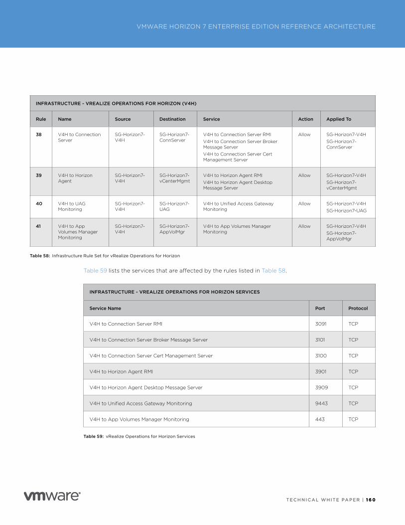
T E C H N I C A L W H I T E PA P E R | 1 6 0
VMWARE HORIZON 7 ENTERPRISE EDITION REFERENCE ARCHITECTURE
T E C H N I C A L W H I T E PA P E R | 1 6 0
INFRASTRUCTURE - VREALIZE OPERATIONS FOR HORIZON (V4H)
Rule Name Source Destination Service Action Applied To
38 V4H to Connection Server
SG-Horizon7-V4H
SG-Horizon7-ConnServer
V4H to Connection Server RMIV4H to Connection Server Broker Message ServerV4H to Connection Server Cert Management Server
Allow SG-Horizon7-V4HSG-Horizon7-ConnServer
39 V4H to Horizon Agent
SG-Horizon7-V4H
SG-Horizon7-vCenterMgmt
V4H to Horizon Agent RMIV4H to Horizon Agent Desktop Message Server
Allow SG-Horizon7-V4HSG-Horizon7-vCenterMgmt
40 V4H to UAG Monitoring
SG-Horizon7-V4H
SG-Horizon7-UAG
V4H to Unified Access Gateway Monitoring
Allow SG-Horizon7-V4HSG-Horizon7-UAG
41 V4H to App Volumes Manager Monitoring
SG-Horizon7-V4H
SG-Horizon7-AppVolMgr
V4H to App Volumes Manager Monitoring
Allow SG-Horizon7-V4HSG-Horizon7-AppVolMgr
Table 58: Infrastructure Rule Set for vRealize Operations for Horizon
Table 59 lists the services that are affected by the rules listed in Table 58 .
INFRASTRUCTURE - VREALIZE OPERATIONS FOR HORIZON SERVICES
Service Name Port Protocol
V4H to Connection Server RMI 3091 TCP
V4H to Connection Server Broker Message Server 3101 TCP
V4H to Connection Server Cert Management Server 3100 TCP
V4H to Horizon Agent RMI 3901 TCP
V4H to Horizon Agent Desktop Message Server 3909 TCP
V4H to Unified Access Gateway Monitoring 9443 TCP
V4H to App Volumes Manager Monitoring 443 TCP
Table 59: vRealize Operations for Horizon Services
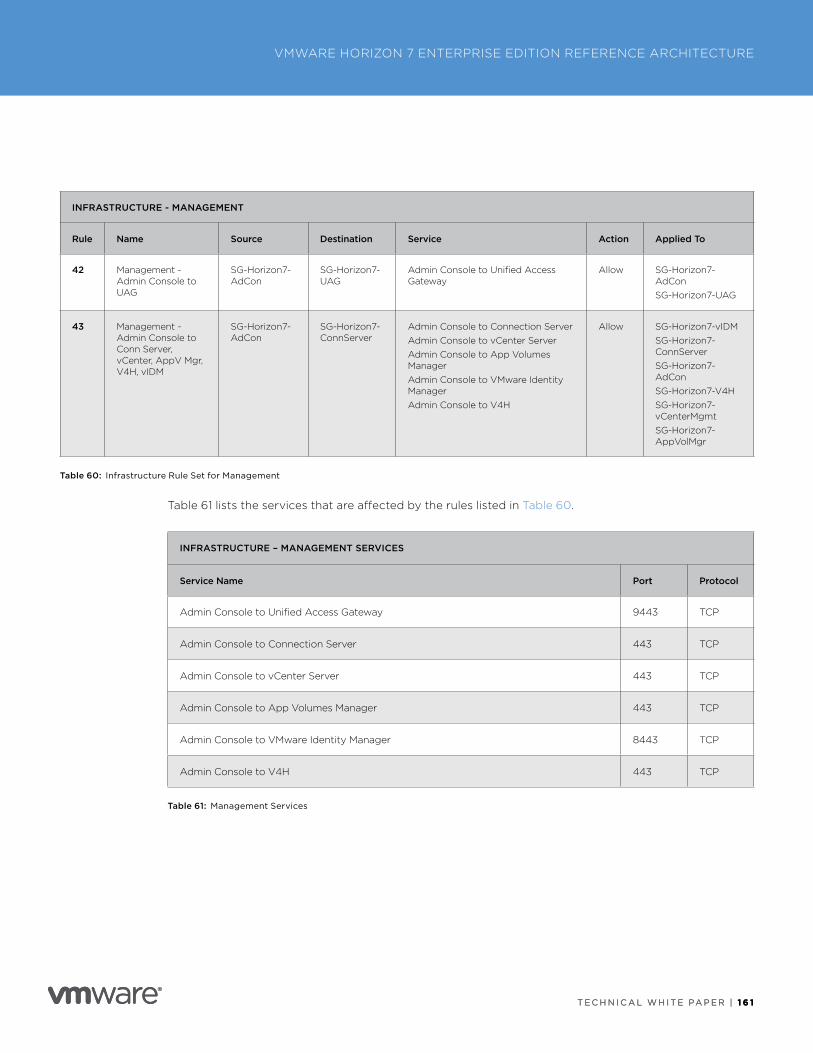
T E C H N I C A L W H I T E PA P E R | 1 6 1
VMWARE HORIZON 7 ENTERPRISE EDITION REFERENCE ARCHITECTURE
T E C H N I C A L W H I T E PA P E R | 1 6 1
INFRASTRUCTURE - MANAGEMENT
Rule Name Source Destination Service Action Applied To
42 Management - Admin Console to UAG
SG-Horizon7-AdCon
SG-Horizon7-UAG
Admin Console to Unified Access Gateway
Allow SG-Horizon7-AdConSG-Horizon7-UAG
43 Management - Admin Console to Conn Server, vCenter, AppV Mgr, V4H, vIDM
SG-Horizon7-AdCon
SG-Horizon7-ConnServer
Admin Console to Connection ServerAdmin Console to vCenter ServerAdmin Console to App Volumes ManagerAdmin Console to VMware Identity ManagerAdmin Console to V4H
Allow SG-Horizon7-vIDMSG-Horizon7-ConnServerSG-Horizon7-AdConSG-Horizon7-V4HSG-Horizon7-vCenterMgmtSG-Horizon7-AppVolMgr
Table 60: Infrastructure Rule Set for Management
Table 61 lists the services that are affected by the rules listed in Table 60 .
INFRASTRUCTURE – MANAGEMENT SERVICES
Service Name Port Protocol
Admin Console to Unified Access Gateway 9443 TCP
Admin Console to Connection Server 443 TCP
Admin Console to vCenter Server 443 TCP
Admin Console to App Volumes Manager 443 TCP
Admin Console to VMware Identity Manager 8443 TCP
Admin Console to V4H 443 TCP
Table 61: Management Services
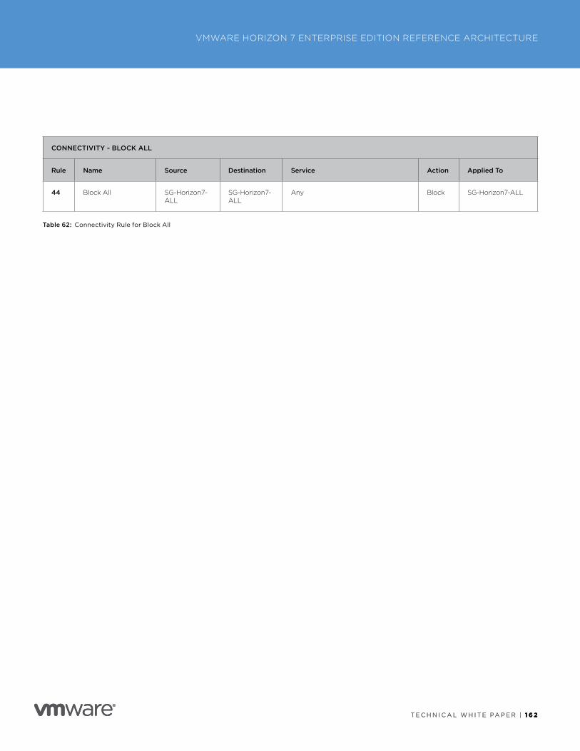
T E C H N I C A L W H I T E PA P E R | 1 6 2
VMWARE HORIZON 7 ENTERPRISE EDITION REFERENCE ARCHITECTURE
T E C H N I C A L W H I T E PA P E R | 1 6 2
CONNECTIVITY - BLOCK ALL
Rule Name Source Destination Service Action Applied To
44 Block All SG-Horizon7-ALL
SG-Horizon7-ALL
Any Block SG-Horizon7-ALL
Table 62: Connectivity Rule for Block All
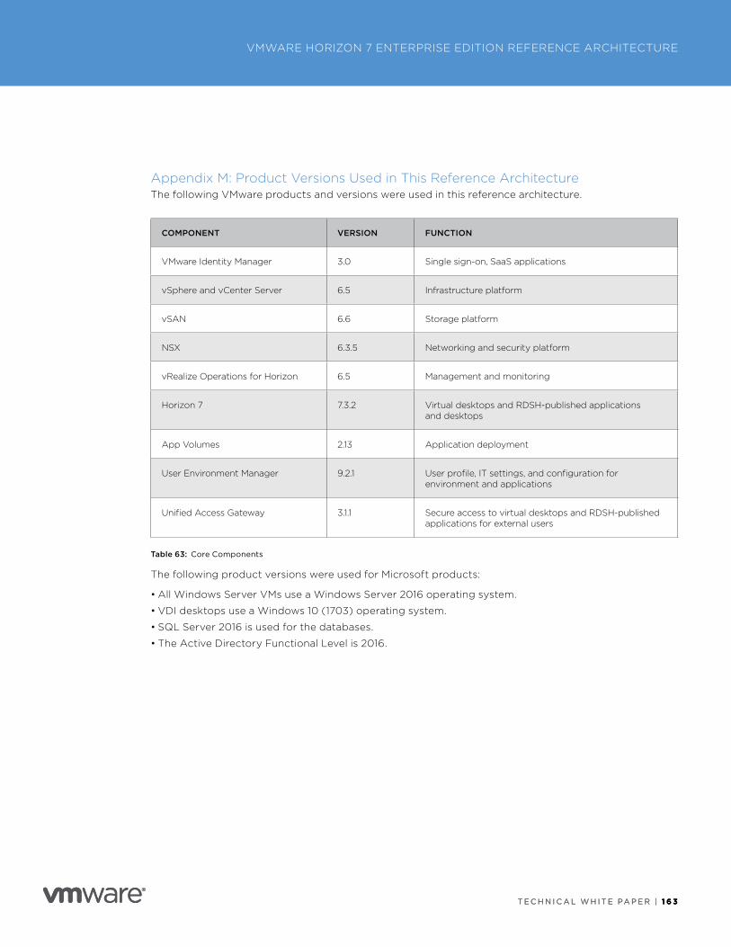
T E C H N I C A L W H I T E PA P E R | 1 6 3
VMWARE HORIZON 7 ENTERPRISE EDITION REFERENCE ARCHITECTURE
T E C H N I C A L W H I T E PA P E R | 1 6 3
Appendix M: Product Versions Used in This Reference ArchitectureThe following VMware products and versions were used in this reference architecture .
COMPONENT VERSION FUNCTION
VMware Identity Manager 3 .0 Single sign-on, SaaS applications
vSphere and vCenter Server 6 .5 Infrastructure platform
vSAN 6 .6 Storage platform
NSX 6 .3 .5 Networking and security platform
vRealize Operations for Horizon 6 .5 Management and monitoring
Horizon 7 7 .3 .2 Virtual desktops and RDSH-published applications and desktops
App Volumes 2 .13 Application deployment
User Environment Manager 9 .2 .1 User profile, IT settings, and configuration for environment and applications
Unified Access Gateway 3 .1 .1 Secure access to virtual desktops and RDSH-published applications for external users
Table 63: Core Components
The following product versions were used for Microsoft products:
• All Windows Server VMs use a Windows Server 2016 operating system .
• VDI desktops use a Windows 10 (1703) operating system .
• SQL Server 2016 is used for the databases .
• The Active Directory Functional Level is 2016 .
T E C H N I C A L W H I T E PA P E R | 1 6 4
VMWARE HORIZON 7 ENTERPRISE EDITION REFERENCE ARCHITECTURE
T E C H N I C A L W H I T E PA P E R | 1 6 4
Additional ResourcesLoad Balancing across VMware Unified Access Gateway Appliances
Load Balancing VMware Unified Access Gateway (an F5 Deployment Guide)
Network Ports in VMware Horizon 7
VMware App Volumes Documentation Center
VMware Horizon 7 Documentation Center
VMware Horizon 7 Enterprise Edition Multi-Site Reference Architecture
VMware Identity Manager Documentation Center
VMware NSX for vSphere Documentation Center
VMware Unified Access Gateway Documentation Center
VMware User Environment Manager Documentation Center
VMware vSphere Documentation Center
About the Authors Graeme Gordon is a Senior Staff End-User-Computing (EUC) Architect in End-User-Computing Technical Marketing, VMware .
Frank Anderson is a Solutions Architect in VMware End-User-Computing Technical Marketing .
Hilko Lantinga is an End-User Computing Architect in VMware End-User-Computing Technical Marketing .
Geoff Wilmington is a Senior Technical Product Manager with the Networking and Security Business Unit, VMware .
Donal Geary is a Reference Architect Engineer in End-User-Computing Technical Marketing, VMware .
Caroline Arakelian is a Senior Technical Marketing Manager, End-User-Computing Technical Marketing, VMware .
Alex Birch, formerly of VMware End-User-Computing Technical Marketing, co-authored the original version of this white paper .
Chris Halstead, Staff Engineer at VMware, co-authored the original version of this white paper .
Kevin Sheehan, End-User-Computing Senior Product Manager, co-authored the original version of this white paper .
Stéphane Asselin, Lead Product Architect in VMware End-User Computing, co-authored the original version of this white paper .
Matt Coppinger, Director of Technical Marketing and Enablement, End-User Computing, VMware, co-authored the original version of this white paper .
To comment on this paper, contact VMware End-User-Computing Technical Marketing at mailto:euc_tech_content_feedback@vmware .com .
VMware, Inc. 3401 Hillview Avenue Palo Alto CA 94304 USA Tel 877-486-9273 Fax 650-427-5001 www .vmware .comCopyright © 2018 VMware, Inc . All rights reserved . This product is protected by U .S . and international copyright and intellectual property laws . VMware products are covered by one or more patents listed at http://www .vmware .com/go/patents . VMware is a registered trademark or trademark of VMware, Inc . in the United States and/or other jurisdictions . All other marks and names mentioned herein may be trademarks of their respective companies . Item No: 5212-VMW-WP-HORIZON73-ENT-ED-RA-USLET-20180131 1/18