Embed Size (px)
Citation preview
SOLENOID DRIVEN METERING PUMPS
EN
VMS - VMSA - VMS PER
OPE
RATI
NG
MAN
UAL
Progettato da: Controllato da: Data:
Edizione Foglio/A4 EMEC_Verticale
Massimo_F Massimo_F 13/06/2013
00
Toll. Gen.±0.05
Peso Lordo: Peso Netto:
Materiale:
1 1
VMSA
VMS PER
VMS
2
This operating instructions contains safety information that if ignored can endanger life or result in serious injury.
Read these instructions carefully before use and keep them for future reference. The original instruction is in Italian. All non-Italian instructions are translations of the original instruction.
Information and specifications on this manual could be uncorrect or could have printing errors.Specifications are subject to change without notice.
Version: R1-08-13
NORME CEEC RULES (STANDARD EC)NORMAS DE LA CE
Direttiva Basso VoltaggioLow Voltage DirectiveDirectiva de baja tensión
Direttiva EMC Compatibilità ElettromagneticaEMC electromagnetic compatibility directiveEMC directiva de compatibilidad electromagnética
Norme armonizzate europee nell’ambito della direttivaEuropean harmonized standards underdirectiveLas normas europeas armonizadas conforme a la directiva
2006/95/CE
2004/108/CE
⎬
⎬2006/42/CE⎬
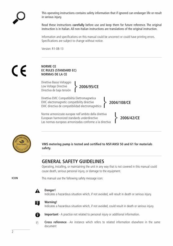
Danger! Indicates a hazardous situation which, if not avoided, will result in death or serious injury.
Warning! Indicates a hazardous situation which, if not avoided, could result in death or serious injury.
Important - A practice not related to personal injury or additional information.
⎘ Cross reference - An instance which refers to related information elsewhere in the same document
GENERAL SAFETY GUIDELINESOperating, installing, or maintaining the unit in any way that is not covered in this manual could cause death, serious personal injury, or damage to the equipment.
This manual use the following safety message icon: ICON
VMS metering pump is tested and certified to NSF/ANSI 50 and 61 for materials safety.
3
PURPOSE OF USE AND SAFETY
METERING PUMP IS INTENDED FOR ChEMICAL DOSING AND DRINkING WATER TREATMENT.
Do not use in explosive area (EX).Do not use with flammable chemicals.Do not use with radioactive chemicals.
Use after a proper installation.
Use the pump in accordance with the data and specifications printed on the label.
Do not modify or use in a manner inconsistent with the provisions of the operating manual.
keep the pump protected from sun and water. Avoid water splashes.
In emergencies the pump should be switched off immediately. Disconnect the power cable from the power supply.
When using pump with aggressive chemicals observe the regulations concerning the transport and storage of aggressive fluids.
When installing always observe national regulations.
Manufacturer is not liable for any unauthorized use or misuse of this product that may cause injury, damage to persons or materials.
Pump must be accessible at all times for both operating and servicing. Access must not be obstructed in any way.
Feeder should be interlocked with a no-flow protection device.
Pump and accessories must be serviced and repaired by qualified and authorized personnel only.
Before any operation:• always read chemical Material Safety Data Sheet (MSDS);• always wear protective clothing;• always discharge the liquid end before servicing the pump.• empty and rinse the liquid end before work on a pump which has been used with
hazardous or unknown chemicals.
This equipment requires regular maintenance to ensure potability requirements of the water and maintenance of improvements as declared by the manufaturer.
4
ENVIRONMENTAL SAFETY
LABELS
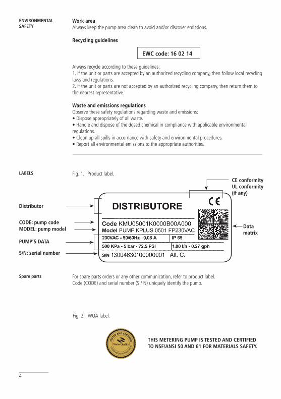
Distributor
CODE: pump codeMODEL: pump model
PUMP’S DATA
S/N: serial number
Data matrix
CE conformityUL conformity (if any)
For spare parts orders or any other communication, refer to product label.Code (CODE) and serial number (S / N) uniquely identify the pump.
Spare parts
Fig. 1. Product label.
Fig. 2. WQA label.
ThIS METERING PUMP IS TESTED AND CERTIFIED TO NSF/ANSI 50 AND 61 FOR MATERIALS SAFETY.
Work areaAlways keep the pump area clean to avoid and/or discover emissions.
Recycling guidelines
EWC code: 16 02 14
Always recycle according to these guidelines:1. If the unit or parts are accepted by an authorized recycling company, then follow local recycling laws and regulations.2. If the unit or parts are not accepted by an authorized recycling company, then return them to the nearest representative.
Waste and emissions regulationsObserve these safety regulations regarding waste and emissions:• Dispose appropriately of all waste.• Handle and dispose of the dosed chemical in compliance with applicable environmental regulations.• Clean up all spills in accordance with safety and environmental procedures.• Report all environmental emissions to the appropriate authorities.
5
1. Introduction
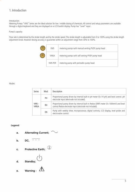
Introduction:Metering Pumps “VMS” Series are the ideal solution for low / middle dosing of chemicals. All control and setup parameters are available through a digital keyboard and they are displayed on a LCD backlit display. Pump has “Level” input .
Pump’s capacity
Flow rate is determined by the stroke length and by the stroke speed. The stroke length is adjustable from 0 to 100% using the stroke length adjustment knob. However dosing accuracy is guarantee within an adjustment range from 30% to 100%.
VMS metering pumps with manual venting PVDF pump head
VMSA metering pumps with self venting PVDF pump head
VMS PER metering pump with peristaltic pump head
Modes:
Legend:
a. Alternating Current;
b. DC,
c. Protective Earth;
d. Standby;
e. Warning -
Series Mod. Description
VMS - VMSA
PHProportional pump driven by internal built-in pH meter (0÷14 pH) and level control. pH electrode input (electrode not included).
RHProportional pump driven by internal built-in Redox (ORP) meter (0÷1000mV) and level control.Redox electrode input (electrode not included).
ENPump with weekly timer, microprocessor, digital controls, LCD display, level probe and electrovalve control.
6
2. Unpacking
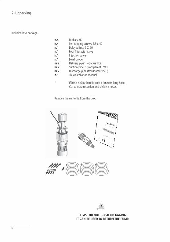
Included into package:
n.4 Dibbles ø6 n.4 Self tapping screws 4,5 x 40n.1 Delayed fuse 5 X 20 n.1 Foot filter with valve n.1 Injection valven.1 Level probe m 2 Delivery pipe* (opaque PE) m 2 Suction pipe * (transparent PVC)m 2 Discharge pipe (transparent PVC)n.1 This installation manual
* If hose is 6x8 there is only a 4meters long hose. Cut to obtain suction and delivery hoses.
Remove the contents from the box.
PLEASE DO NOT TRASh PACkAGING. IT CAN BE USED TO RETURN ThE PUMP.
7
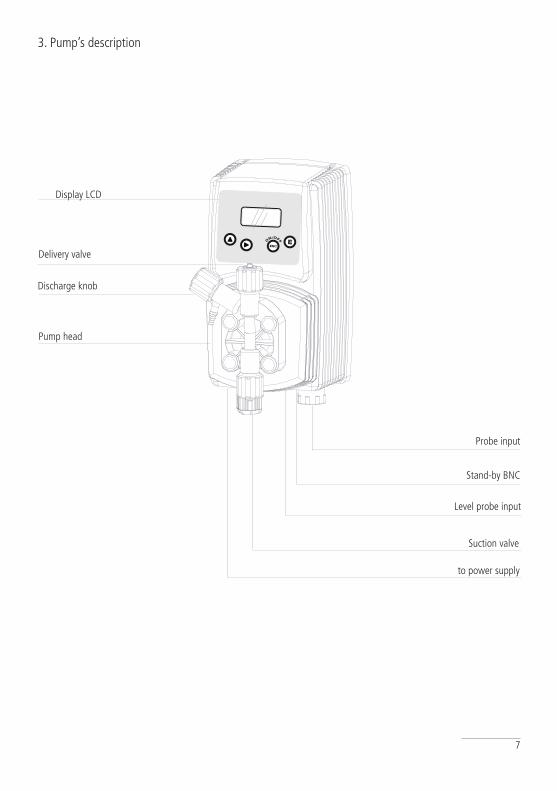
3. Pump’s description
Delivery valve
Discharge knob
Stand-by BNC
Level probe input
Pump head
Display LCD
Suction valve
to power supply
Probe input
8
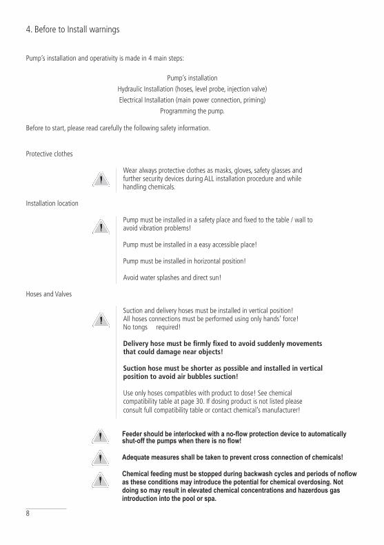
4. Before to Install warnings
Pump’s installation and operativity is made in 4 main steps:
Pump’s installation
Hydraulic Installation (hoses, level probe, injection valve)
Electrical Installation (main power connection, priming)
Programming the pump.
Before to start, please read carefully the following safety information.
Protective clothes
Wear always protective clothes as masks, gloves, safety glasses and further security devices during ALL installation procedure and while handling chemicals. Installation location
Pump must be installed in a safety place and fixed to the table / wall to avoid vibration problems!
Pump must be installed in a easy accessible place!
Pump must be installed in horizontal position!
Avoid water splashes and direct sun!
Hoses and Valves
Suction and delivery hoses must be installed in vertical position! All hoses connections must be performed using only hands’ force! No tongs required!
Delivery hose must be firmly fixed to avoid suddenly movements that could damage near objects!
Suction hose must be shorter as possible and installed in vertical position to avoid air bubbles suction!
Use only hoses compatibles with product to dose! See chemical compatibility table at page 30. If dosing product is not listed please consult full compatibility table or contact chemical’s manufacturer!
Feeder should be interlocked with a no-flow protection device to automatically shut-off the pumps when there is no flow!
Adequate measures shall be taken to prevent cross connection of chemicals!
Chemical feeding must be stopped during backwash cycles and periods of noflow as these conditions may introduce the potential for chemical overdosing. Not doing so may result in elevated chemical concentrations and hazerdous gas introduction into the pool or spa.
9
N.O.
3
4
1
8
5 2
6 7
910
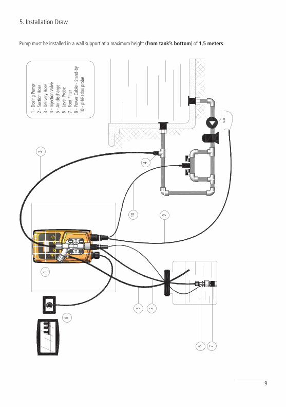
5. Installation Draw
Pump must be installed in a wall support at a maximum height (from tank’s bottom) of 1,5 meters.
1 - D
osin
g Pu
mp
2 - S
uctio
n Ho
se3
- Del
iver
y Ho
se4
- Inj
ectio
n Va
lve
5 - A
ir di
scha
rge
6 - L
evel
Pro
be7
- Foo
t Filt
er8
- Pow
er C
able
- St
and-
by10
- pH
/Red
ox p
robe
10
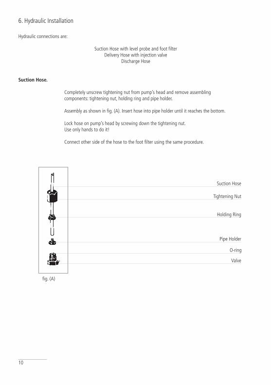
6. Hydraulic Installation
Suction Hose
Tightening Nut
Holding Ring
Pipe Holder
O-ring
Valve
Hydraulic connections are:
Suction Hose with level probe and foot filterDelivery Hose with injection valve
Discharge Hose
Suction hose.
Completely unscrew tightening nut from pump’s head and remove assembling components: tightening nut, holding ring and pipe holder.
Assembly as shown in fig. (A). Insert hose into pipe holder until it reaches the bottom.
Lock hose on pump’s head by screwing down the tightening nut. Use only hands to do it!
Connect other side of the hose to the foot filter using the same procedure.
fig. (A)
11
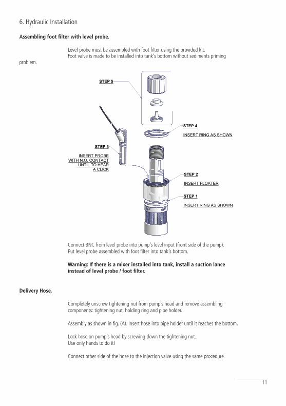
Assembling foot filter with level probe.
Level probe must be assembled with foot filter using the provided kit. Foot valve is made to be installed into tank’s bottom without sediments priming problem.
Connect BNC from level probe into pump’s level input (front side of the pump). Put level probe assembled with foot filter into tank’s bottom.
Warning: If there is a mixer installed into tank, install a suction lance instead of level probe / foot filter.
Delivery hose.
Completely unscrew tightening nut from pump’s head and remove assembling components: tightening nut, holding ring and pipe holder.
Assembly as shown in fig. (A). Insert hose into pipe holder until it reaches the bottom.
Lock hose on pump’s head by screwing down the tightening nut. Use only hands to do it!
Connect other side of the hose to the injection valve using the same procedure.
6. Hydraulic Installation
Progettato da Controllato da Modificato da, il Data
Edizione Foglio
/
076.0147.1
Massimo_F 24/10/2003
00
Toll. Gen.`0.05
Materiale:
STEP 5
FILTRO DI ASPIRAZIONE CON SONDA DI LIVELLO - CONTATTO N.O.
FP+CE+PVDF
1 1
STEP 2 INSERT FLOATER
STEP 1 INSERT RING AS SHOWN
STEP 4 INSERT RING AS SHOWN
STEP 3
INSERT PROBEWITH N.O. CONTACT
UNTIL TO HEARA CLICK
12
6. Hydraulic Installation
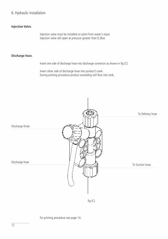
Discharge hose.
Insert one side of discharge hose into discharge connector as shown in fig (C).
Insert other side of discharge hose into product’s tank. During priming procedure product exceeding will flow into tank.
For priming procedure see page 14.
Injection Valve.
Injection valve must be installed on plant from water’s input. Injection valve will open at pressure greater than 0,3bar.
fig (C)
Discharge hose
Discharge Knob
To Delivery hose
To Suction hose
13
6. Hydraulic Installation
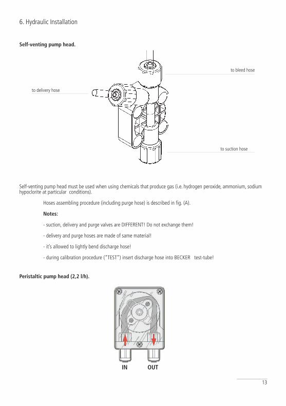
Self-venting pump head.
Self-venting pump head must be used when using chemicals that produce gas (i.e. hydrogen peroxide, ammonium, sodium hypoclorite at particular conditions).
Hoses assembling procedure (including purge hose) is described in fig. (A).
Notes:
- suction, delivery and purge valves are DIFFERENT! Do not exchange them!
- delivery and purge hoses are made of same material!
- it’s allowed to lightly bend discharge hose!
- during calibration procedure (“TEST”) insert discharge hose into BECKER test-tube!
to bleed hose
to suction hose
to delivery hose
IN OUT
Peristaltic pump head (2,2 l/h).

14
7. Electrical Installation
All electrical connections must be performed by AUThORIZED AND QUALIFIED personnel only. Before to proceed, please, verify the following steps:
- verify that pump’s label values are compatible with main power supply.
- pump must be connected to a plant with a differential switch (0,03A sensitivity) if there isn’t a good ground.
- to avoid damages to the pump do not install it in parallel with heavy inductance load (for example: engines). A relay switch must be used. See below picture.
P - Dosing Pump R - Relay
I - Switch or safety deviceE - Electrovalve or inductance load
A - Main Power
WARNINGIF EQUIPMENT IS NOT SUPPLIED WITH A PLUG:
a) a switch or circuit-breaker shall be included in the building installationb) it shall be in close proximity to the equipment and within easy reach of the operator
c) it shall be marked as the disconnetting device for the equipment
WARNINGIF EQUIPMENT IS SUPPLIED WITH A PLUG:
If an appliance coupler or separable plug is used as the disconnecting device, it shall be readily identifiable and easily reached by the operator. For single-phase portable equipment, a plug on a cord of length not greater than 3m is considered to be easily reached.
15
7. Electrical Installation
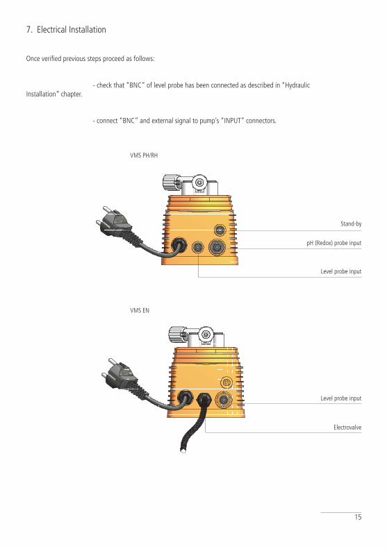
Once verified previous steps proceed as follows:
- check that “BNC” of level probe has been connected as described in “Hydraulic Installation” chapter.
- connect “BNC” and external signal to pump’s “INPUT” connectors.
Level probe input
Stand-by
1
1
2
2
3
3
4
4
5
5
6
6
A A
B B
C C
D D
federico.renzi 08/05/2008
Progettato da Controllato da Approvato da Data
1 / 1 Edizione Foglio
Data
1
1
2
2
3
3
4
4
5
5
6
6
A A
B B
C C
D D
federico.renzi 08/05/2008
Progettato da Controllato da Approvato da Data
1 / 1 Edizione Foglio
Data
VMS PH/RH
VMS EN
Level probe input
Electrovalve
pH (Redox) probe input
16
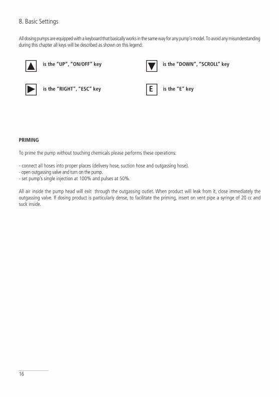
All dosing pumps are equipped with a keyboard that basically works in the same way for any pump’s model. To avoid any misunderstanding during this chapter all keys will be described as shown on this legend:
is the “UP”, “ON/OFF” key is the “DOWN”, “SCROLL” key
is the “RIGhT”, “ESC” key is the “E” keyE
8. Basic Settings
PRIMING
To prime the pump without touching chemicals please performs these operations:
- connect all hoses into proper places (delivery hose, suction hose and outgassing hose).- open outgassing valve and turn on the pump. - set pump’s single injection at 100% and pulses at 50%.
All air inside the pump head will exit through the outgassing outlet. When product will leak from it, close immediately the outgassing valve. If dosing product is particularly dense, to facilitate the priming, insert on vent pipe a syringe of 20 cc and suck inside.
17
9. Programming the “VMS PH” pump
PROGRAMMING “VMS Ph” PUMP
Entering in program mode
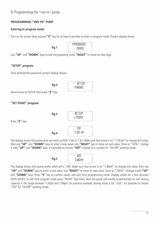
Turn on the pump. Keep pressed “E” key for at least 4 seconds to enter in program mode. Pump’s display shows:
fig.1
Use “UP” and “DOWN” keys to edit the password, press “RIGhT” to move on next digit.
“SETUP” program
Once entered the password, pump’s display shows:
fig.2
Move arrow on SETUP then press “E” key:
“SET POINT” program
fig.3 Press “E” key:
fig.4
The display shows that pump does not work at 00% if pH is 7.30. Make sure that arrow is on “7.30 pH” to change this value, then use “UP” and “DOWN” keys to enter a new value. Use “RIGhT” key to move on next value. Once on “00%”, change it with “UP” and “DOWN” keys. It’s possible to choose “OFF” instead of a number for “On/Off” working mode.
fig.5
The display shows that pump works when pH is 7.80. Make sure that arrow is on “7.80pH” to change this value, then use “UP” and “DOWN” keys to enter a new value. Use “RIGhT” to move on next value. Once on “100%”, change it with “UP” and “DOWN” keys. Press “E” key to confirm values and quit from programming mode. Display shows for a few seconds: DATA SAVED. To exit from program mode press “RIGHT” key twice. Now the pump will modify proportionally its own dosing capacity in the range between 7.30pH and 7.80pH. On previous example, dosing mode is for “acid”. It’s possible to choose “ON” for “On/Off” working mode.
PASSWORD
->0000
-> SETUP
PARAM
SETUP
1 POINT
->00%
7.30 PH
->100%
7.80PH

18
Probe calibration
To obtain a reliable measurement it is necessary (during installation) calibrate the probe. To do this, two buffer solutions are needed: a 7.00pH buffer solution and a 4.00pH or 9.00pH buffer solution. Proceed as follows:
1) Measure buffer solution temperature and verify if it is the same printed on solution’s label.2) Insert probe’s connector (blue colour) into pump’s input connector.3) Remove protective cap from probe and wash it into water. Then dry it.
Into “Setup” menu (fig.3), choose “2)Calib” then press “E” key. The display shows:
fig.6
“R” means buffer solution reading value and “C” the calibration to refer to. During the calibration the “R” value could be different from the buffer solution value. Wait a stable reading in “R”. Dip probe in a 7.00 pH buffer solution and use “UP” and “DOWN” keys to change the value in “C:” to have buffer solution value. Wait a stable reading in “R:” then press “E” key to confirm this first calibration. Pump will show:
fig.7
Remove the probe from first buffer solution and repeat the cleaning procedure. Then dip probe into second buffer solution (for example 4.00 pH) and use “UP” and “DOWN” keys to change the value in “C:” to have buffer solution value. Wait a stable reading in “R:” then press “E” key to confirm. The pump will show the new values for a while and will return to main menu.
fig.8
If calibration process fails the pump will show “PH CALIB FAILED”. Not changing any value the program will return to “Calib” mode. To exit press “RIGHT” key twice.
DELAY
In main menu choose “PARAM” (fig.2) and press “E” key. Display shows:
fig.9
The -> arrow is on “DEL”. This value is pump’s waiting time after any start up procedure: pump will wait set time before start dosing every time it is powered on. Use “UP” and “DOWN” keys to change this value. Waiting time may be set from 1 to 60 minutes.
9. Programming the pump
R:7.20PH
C:7.00PH
DEL:->00
0000
R:7.20PH
C:7.00PH
59 MV/PH
-000MV
19
9. Programming the pump
PASSWORD
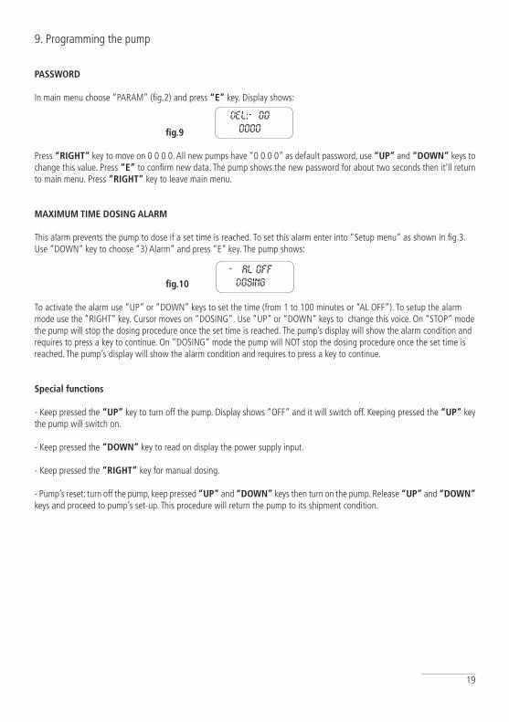
In main menu choose “PARAM” (fig.2) and press “E” key. Display shows:
fig.9
Press “RIGhT” key to move on 0 0 0 0. All new pumps have “0 0 0 0” as default password, use “UP” and “DOWN” keys to change this value. Press “E” to confirm new data. The pump shows the new password for about two seconds then it’ll return to main menu. Press “RIGhT” key to leave main menu.
MAXIMUM TIME DOSING ALARM
This alarm prevents the pump to dose if a set time is reached. To set this alarm enter into “Setup menu” as shown in fig.3. Use “DOWN” key to choose “3) Alarm” and press “E” key. The pump shows:
fig.10
To activate the alarm use “UP” or “DOWN” keys to set the time (from 1 to 100 minutes or “AL OFF”). To setup the alarm mode use the “RIGHT” key. Cursor moves on “DOSING”. Use “UP” or “DOWN” keys to change this voice. On “STOP” mode the pump will stop the dosing procedure once the set time is reached. The pump’s display will show the alarm condition and requires to press a key to continue. On “DOSING” mode the pump will NOT stop the dosing procedure once the set time is reached. The pump’s display will show the alarm condition and requires to press a key to continue.
Special functions
- Keep pressed the “UP” key to turn off the pump. Display shows “OFF” and it will switch off. Keeping pressed the “UP” key the pump will switch on.
- Keep pressed the “DOWN” key to read on display the power supply input.
- Keep pressed the “RIGhT” key for manual dosing.
- Pump’s reset: turn off the pump, keep pressed “UP” and “DOWN” keys then turn on the pump. Release “UP” and “DOWN” keys and proceed to pump’s set-up. This procedure will return the pump to its shipment condition.
DEL:->00
0000
-> AL OFF
DOSING
20
PROGRAMMING “VMS Rh” PUMP
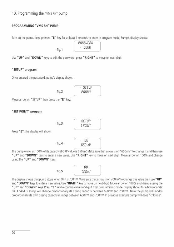
Turn on the pump. Keep pressed “E” key for at least 4 seconds to enter in program mode. Pump’s display shows:
fig.1
Use “UP” and “DOWN” keys to edit the password, press “RIGhT” to move on next digit.
“SETUP” program
Once entered the password, pump’s display shows:
fig.2
Move arrow on “SETUP” then press the “E” key:
“SET POINT” program
fig.3
Press “E”, the display will show:
fig.4
The pump works at 100% of its capacity if ORP value is 650mV. Make sure that arrow is on “650mV” to change it and then use “UP” and “DOWN” keys to enter a new value. Use “RIGhT” key to move on next digit. Move arrow on 100% and change using the “UP” and “DOWN” keys.
fig.5
The display shows that pump stops when ORP is 700mV. Make sure that arrow is on 700mV to change this value then use “UP” and “DOWN” keys to enter a new value. Use “RIGhT” key to move on next digit. Move arrow on 100% and change using the “UP” and “DOWN” keys. Press “E” key to confirm values and quit from programming mode. Display shows for a few seconds: DATA SAVED. Pump will change proportionally its dosing capacity between 650mV and 700mV. Now the pump will modify proportionally its own dosing capacity in range between 650mV and 700mV. In previous example pump will dose “chlorine”.
10. Programming the “VMS RH” pump
password
->0000
setup
1 point
->setup
param
->100%
650 mv
->00%
700mv
21
Probe calibration
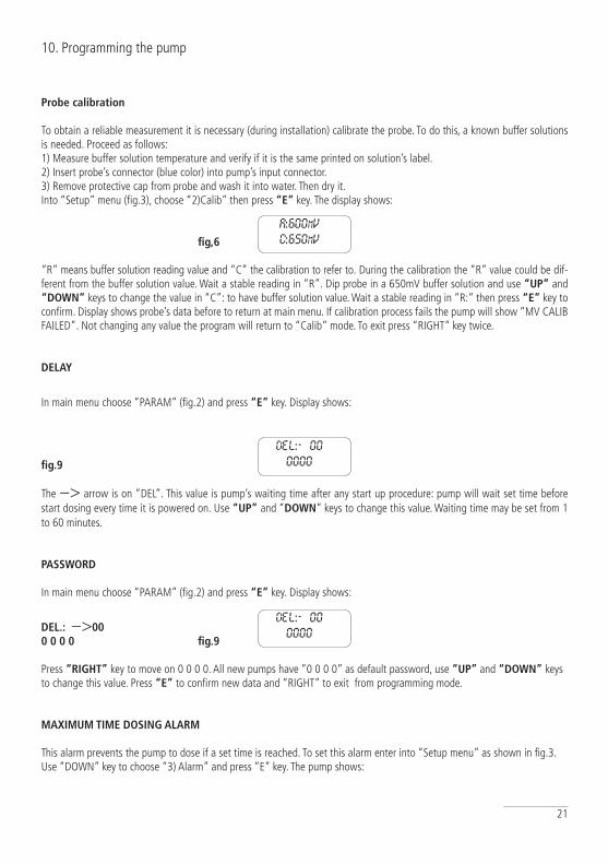
To obtain a reliable measurement it is necessary (during installation) calibrate the probe. To do this, a known buffer solutions is needed. Proceed as follows: 1) Measure buffer solution temperature and verify if it is the same printed on solution’s label.2) Insert probe’s connector (blue color) into pump’s input connector.3) Remove protective cap from probe and wash it into water. Then dry it.Into “Setup” menu (fig.3), choose “2)Calib” then press “E” key. The display shows:
fig,6
“R” means buffer solution reading value and “C” the calibration to refer to. During the calibration the “R” value could be dif-ferent from the buffer solution value. Wait a stable reading in “R”. Dip probe in a 650mV buffer solution and use “UP” and “DOWN” keys to change the value in “C”: to have buffer solution value. Wait a stable reading in “R:” then press “E” key to confirm. Display shows probe’s data before to return at main menu. If calibration process fails the pump will show “MV CALIB FAILED”. Not changing any value the program will return to “Calib” mode. To exit press “RIGHT” key twice.
DELAY
In main menu choose “PARAM” (fig.2) and press “E” key. Display shows:
fig.9
The −> arrow is on “DEL”. This value is pump’s waiting time after any start up procedure: pump will wait set time before start dosing every time it is powered on. Use “UP” and “DOWN” keys to change this value. Waiting time may be set from 1 to 60 minutes.
PASSWORD
In main menu choose “PARAM” (fig.2) and press “E” key. Display shows:
DEL.: −>000 0 0 0 fig.9
Press “RIGhT” key to move on 0 0 0 0. All new pumps have “0 0 0 0” as default password, use “UP” and “DOWN” keys to change this value. Press “E” to confirm new data and “RIGHT” to exit from programming mode.
MAXIMUM TIME DOSING ALARM
This alarm prevents the pump to dose if a set time is reached. To set this alarm enter into “Setup menu” as shown in fig.3. Use “DOWN” key to choose “3) Alarm” and press “E” key. The pump shows:
10. Programming the pump
r:600mv
c:650mv
del:->00
0000
del:->00
0000
22
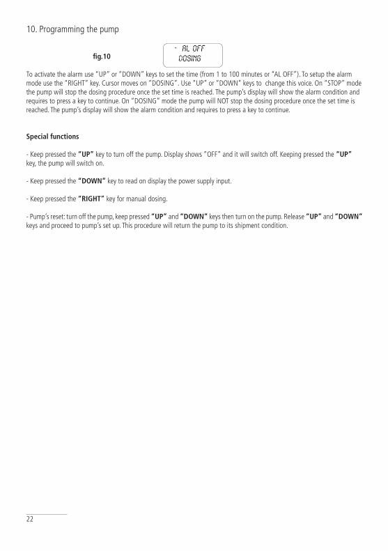
fig.10
To activate the alarm use “UP” or “DOWN” keys to set the time (from 1 to 100 minutes or “AL OFF”). To setup the alarm mode use the “RIGHT” key. Cursor moves on “DOSING”. Use “UP” or “DOWN” keys to change this voice. On “STOP” mode the pump will stop the dosing procedure once the set time is reached. The pump’s display will show the alarm condition and requires to press a key to continue. On “DOSING” mode the pump will NOT stop the dosing procedure once the set time is reached. The pump’s display will show the alarm condition and requires to press a key to continue.
Special functions
- Keep pressed the “UP” key to turn off the pump. Display shows “OFF” and it will switch off. Keeping pressed the “UP” key, the pump will switch on.
- Keep pressed the “DOWN” key to read on display the power supply input.
- Keep pressed the “RIGhT” key for manual dosing.
- Pump’s reset: turn off the pump, keep pressed “UP” and “DOWN” keys then turn on the pump. Release “UP” and “DOWN” keys and proceed to pump’s set up. This procedure will return the pump to its shipment condition.
10. Programming the pump
->al off
dosing

23
PROGRAMMING “VMS EN” PUMP
Turn “ON” the pump. Display shows:
< NEXT >Tue10:57
This is the next dosing time. For example on Tuesday at 10:57 o’clock. Press the “RIGhT” key the display shows:
Cc/day0.0
This is the product’s flow quantity for each day. Press the “RIGhT” key the display shows:
Total cc624.6
Press the “RIGhT” key the display shows:
DATE Mon24/07/00Press the “RIGhT” key the display shows:
TIME9:44:14
Press the “RIGhT” key again, the display will shows the initial picture.
hOW TO PROGRAM “VMS EN” ?
Keep pressed “P” key for at least 4 second. The display shows:
CODE->0 0 0 0
This is the code (password) to enter into pump’s “programming mode”. Press “RIGhT” key to scroll through the numbers and insert the proper code. Default code is 0000. To confirm, press “P” key. The display shows:
-> Manual Clock
Use “UP” (scroll up) and “RIGhT” keys (scroll down). Options are:
ManualClockProgr.InjectWaterCodeLineVoExit
Manual option:
11. Programming the pump
24
To select “Manual” press “P” key (option is selected when -> is on it). The display shows:
Cc 65.0
To start the pump keep pressed the “UP” key. The pump will begin to dose. The dosed quantity does not affect pump’s “Total Counter”. To stop the pump leave the “UP” key. To reset this counter press “RIGhT” key. To exit from “Manual” mode press “P” key.
Clock option:
The display shows date and time. Using “UP” (scroll) and “RIGhT” (change value) keys. Date’s format is: DD/MM/YY. To confirm press “P” key.
Progr. Option:
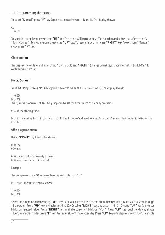
To select “Progr.” press “P” key (option is selected when the -> arrow is on it). The display shows:
1) 0:00Mon OffThe 1) is the program 1 of 16. This pump can be set for a maximum of 16 daily programs.
0:00 is the starting time.
Mon is the dosing day. It is possible to scroll it and choose/add another day. An asterisk* means that dosing is activated for that day.
Off is program’s status.
Using “RIGhT” key the display shows:
0000 cc000 min
0000 cc is product’s quantity to dose. 000 min is dosing time (minutes).
Example:
The pump must dose 400cc every Tuesday and Friday at 14:30.
In “Progr.” Menu the display shows:
1) 0:00Mon Off
Select the program’s number using “UP” key. In this case leave it as appears but remember that it is possible to scroll through 16 programs. Press “UP” key and edit start time (0:00) using “RIGhT” key and enter 1 - 4 - 3 - 0 using “UP” key (the cursor blinks on selected value). Press “RIGhT” key until the cursor will blink on “Mon”. Press “UP” key until the display shows “Tue”. To enable this day press “P” key. An *asterisk confirm selected day. Press “UP” key until display shows “Tue”. To enable
11. Programming the pump
25
this day press “P” key. An *asterisk confirm selected day. Now press “RIGhT” key until the cursor blinks on “On”. Leave as it is. To disable the current program 1 press the “UP” key. Press “RIGhT” key until display shows:
0000 cc000 min
To change the cc value of each digit press “UP” key. To move the cursor to next digit or to “min” press “RIGhT” key. To change min value (minutes required for dosing) for each digit press “UP” key. Move cursor to next digit with “RIGhT” key. The “min” parameter must be calculated on pump’s flow capacity. For example: to dose 400cc using a pump with 0.9 cc/stroke (150 stroke/min), dosing time is about 3 minutes (150x0.9=135cc/min. 400/135=3 minutes). Once entered the values press “P” to confirm and save the program. It is possible to confirm/save the programmed mode during every program’s step. Important note: Do not set two programs with a common time’s period during the same day. Doing this, pump will not accomplish last edited program.
Inject option:
The display shows:
Cc/imp01.00
This value is set after a complete test of plant: flow, backpressure, product to dose, etc...
Water option:
The display shows:
B -> 04 secA 05 sec
“B” means “Before” (min:0 seconds ; max: 60 minutes); “A” means “After” (min:0 seconds; max: 60 minutes). Pump has a 220Vac output for a relay. This function is useful for opening an electrovalve before/after the dosing time. “B” means that output is activated 4 seconds before the program ends. “A” means that output is activated 5 seconds after the program ends. Use “UP” key to change selected value. If entered value is greater than 60 seconds the pump will change unit from seconds to minutes.
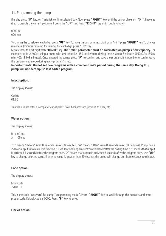
Code option:
The display shows:
Mod Code->0 0 0 0
This is the code (password) for pump “programming mode”. Press “RIGhT” key to scroll through the numbers and enter proper code. Default code is 0000. Press “P” key to enter.
LineVo option:
11. Programming the pump
26
Not editable. It shows (real-time) the power supply voltage according to pump’s working range.
Exit option:
To exit from programming mode.
hOW TO RESET ThE PUMP?
Unplug pump’s power cable from supply and while pressing “UP” and “RIGhT” keys connect the pump’s power cable. The display shows:
ERROR CKMAKE SETPress PTo reset
Press “P” key and pump will shows:
ERASEEPROM
Remember that after pump’s reset all programming values, inject value, date and time, etc have been de-leted and must be entered again.
Note: if pump’s internal battery is completely discharged (pump isn’t powered for more than 6 months) please reinitialize clock to recover it.
11. Programming the pump
27
12. Pump’s messages
PUMP’S MESSAGES
During normal operating mode, the pump may show some messages.
Message: “LOW VOLT”
Description: The pump is low voltage powered. Check main power.
Message: “HIGH VOL”
Description: The pump is high voltage powered. Check main power.
Message: “LOW LEVEL”
Description: Product to dose is near to end. Verify the tank.
Message: “STAND-BY”
Description: The pump is waiting (a specified time) to become operative. See related chapter to set this function.Description: The pump has a N.O. contact (see the picture on page 13). When the contact closes the pump stops and shows the stand-by message until the contact will be opened.
28
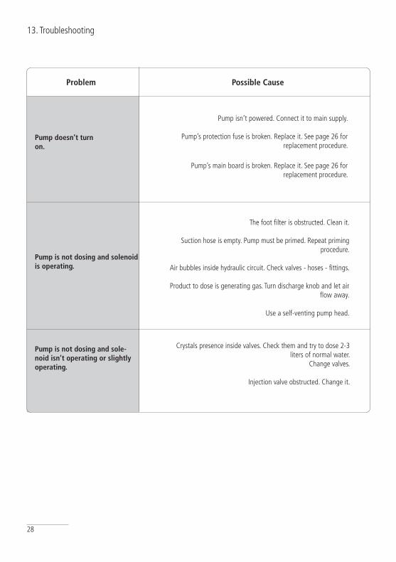
13. Troubleshooting
Problem Possible Cause
Pump doesn’t turn on.
Pump isn’t powered. Connect it to main supply.
Pump’s protection fuse is broken. Replace it. See page 26 for replacement procedure.
Pump’s main board is broken. Replace it. See page 26 for replacement procedure.
Pump is not dosing and solenoid is operating.
The foot filter is obstructed. Clean it.
Suction hose is empty. Pump must be primed. Repeat priming procedure.
Air bubbles inside hydraulic circuit. Check valves - hoses - fittings.
Product to dose is generating gas. Turn discharge knob and let air flow away.
Use a self-venting pump head.
Pump is not dosing and sole-noid isn’t operating or slightly operating.
Crystals presence inside valves. Check them and try to dose 2-3 liters of normal water.
Change valves.
Injection valve obstructed. Change it.
29
14. Fuse and main board replacement
Fuse or main board replacement is allowed to qualified personnel only. Before to operate disconnect the pump from main power and all hydraulic connections.
For fuse replacement is necessary to use a 3x16 and 3x15 screwdriver and a new fuse (same model of old one).
For main board replacement is necessary to use a 3x16 and 3x15 screwdriver and a new main board (same model of old one).
Fuse replacement procedure:
- Remove 6 screws from pump’s back.
- Pull pump’s back cover until it’s completed separated from pump’s front.
- Locate the blown fuse and replace it.
- Reassemble the pump.
- Reinsert screws.
Main board replacement procedure:
- Remove 6 screws from pump’s back.
- Pull pump’s back cover until it’s completed separated from pump’s front.
- Remove board’s screws.
- Completely disconnect wires from main board and replace it. Reinsert screws.
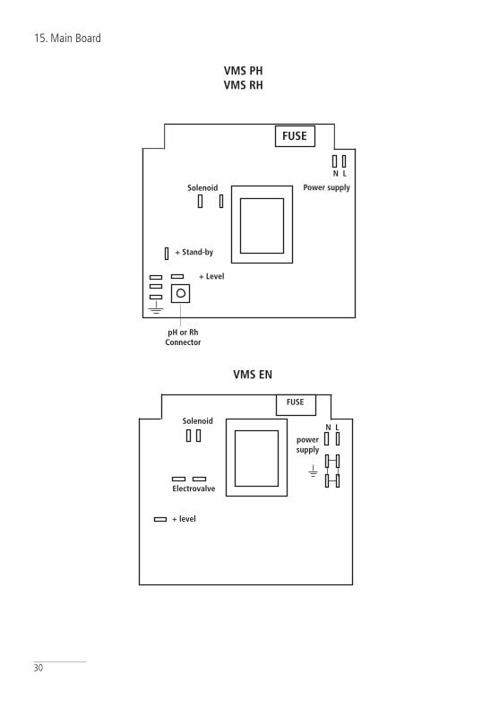
- Reconnect wires to the main board (see enclosed picture).
- Reassemble the pump.
- Reinsert screws.
30
15. Main Board
VMS PhVMS Rh
VMS EN
+ level
N L
FUSE
Solenoid
Electrovalve
power supply
ph or RhConnector
Power supply
FUSE
+ Stand-by
+ Level
Solenoid
N L
31
A Appendix. Maintenance.
Maintenance schedule
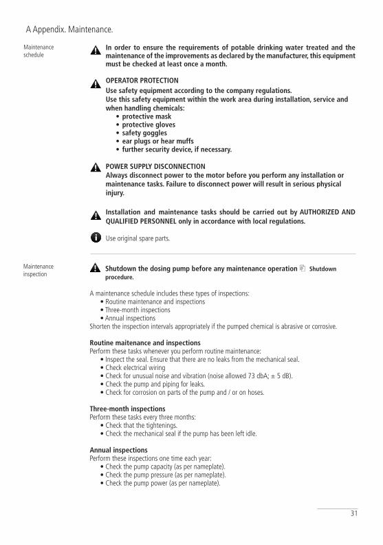
In order to ensure the requirements of potable drinking water treated and the maintenance of the improvements as declared by the manufacturer, this equipment must be checked at least once a month.
OPERATOR PROTECTIONUse safety equipment according to the company regulations.Use this safety equipment within the work area during installation, service and when handling chemicals:
•protective mask•protective gloves•safety goggles•ear plugs or hear muffs• further security device, if necessary.
POWER SUPPLY DISCONNECTIONAlways disconnect power to the motor before you perform any installation ormaintenance tasks. Failure to disconnect power will result in serious physicalinjury.
Installation and maintenance tasks should be carried out by AUThORIZED AND QUALIFIED PERSONNEL only in accordance with local regulations.
Use original spare parts.
Shutdown the dosing pump before any maintenance operation ⎘ Shutdown procedure.
A maintenance schedule includes these types of inspections:• Routine maintenance and inspections• Three-month inspections• Annual inspections
Shorten the inspection intervals appropriately if the pumped chemical is abrasive or corrosive.
Routine maitenance and inspectionsPerform these tasks whenever you perform routine maintenance:
• Inspect the seal. Ensure that there are no leaks from the mechanical seal.• Check electrical wiring• Check for unusual noise and vibration (noise allowed 73 dbA; ± 5 dB).• Check the pump and piping for leaks.• Check for corrosion on parts of the pump and / or on hoses.
Three-month inspectionsPerform these tasks every three months:
• Check that the tightenings.• Check the mechanical seal if the pump has been left idle.
Annual inspectionsPerform these inspections one time each year:
• Check the pump capacity (as per nameplate).• Check the pump pressure (as per nameplate).• Check the pump power (as per nameplate).
Maintenance inspection
32
Shutdown procedure
This procedure ShOULD BE CARRIED OUT BY AUThORIZED AND QUALIFIED PERSONNEL
OPERATOR PROTECTIONUse safety equipment according to the company regulations.Use this safety equipment within the work area during installation, service and when handling chemicals:
•protective mask•protective gloves•safety goggles•ear plugs or hear muffs• further security device, if necessary.
Shutdown the dosing pump before any maintenance operation or before long downtimes.Disconnect power and ensure it cannot be restarted.
Depressurize the system. The liquid may leak splashing.
Drain the chemical from pump head.Release the pressure and disconnect the disharge pipe from the discharge valve.Rinse the pump head and clean all valves.
f the pump performance does not satisfy your process requirements, and the process requirements have not changed, then perform these steps:1. Disassemble the pump.2. Inspect it.3. Replace worn parts.

33
B Appendix. Construction Materials and Technical info
TEChNICAL FEATURES
Power supply: 230 VAC (190÷265 VAC) Power supply: 115 VAC (90÷135 VAC)Power supply: 24 VAC (20÷32 VAC)Power supply: 12 VDC (10÷16 VDC)
Pump Strokes: 0 ÷ 180Suction Height: 1,5 metresEnvironment Temperature: 0 ÷ 45°C (32 ÷ 113°F)Chemical Temperature: 0 ÷ 50°C (32 ÷ 122°F)Installation Class: IIPollution Level: 2Audible Noise: 73dbAPackaging and Transporting Temperature: -10 ÷ +50°C (14 ÷ 122°F)Protection degree: IP 65 (IP54 if peristaltic pump)
MANUFACTURING MATERIALS
Case: PPOPump head: PVDFDiaphragm: PTFEBalls: CERAMIC, GLASS, PTFE, SS *Suction Pipe PVCDelivery Pipe: PE Valve Body: PVDFO-ring: FP, EP, WAX, SI, PTFE *Injection connector PP, PVDF (ceramic, HASTELLOY C276 spring)Level Probe: PP, PVDF *Level probe cable: PEFoot Filter: PP, PVDF *
* as ordered.
ModelFLOW
cc per STROKEMaximum pressure
min cc/h max l/hMin GPH
Max GPH bar PSI
2001 30 1 0,008 0.26 0,1 20 290
1802 60 2 0,02 0.52 0,19 18 261
1804 110 4 0,03 1.05 0,37 18 261
1502 60 2 0,02 0.52 0,19 15 217
1504 110 4 0,03 1.05 0,37 15 217
1505 140 5 0,04 1.32 0,46 15 217
1004 110 4 0,03 1.05 0,37 10 145
1005 140 5 0,04 1.32 0,46 10 145
1010 280 10 0,07 2.64 0,93 10 145
0706 170 6 0,04 1.58 0,56 7 101
0510 280 10 0,07 2.64 0,93 5 72
0512 330 12 0,09 3.17 1,11 5 72
0501 30 1 0,008 0.26 0,1 5 72
0408 220 8 0,06 2.11 0,74 4 58
0310 280 10 0,07 2.64 0,93 3 43
0217 470 17 0,12 4.49 1,57 2 29
0116 440 16 0,11 4.22 1,48 1 14
34
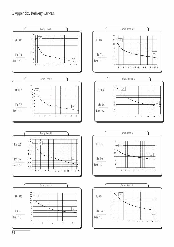
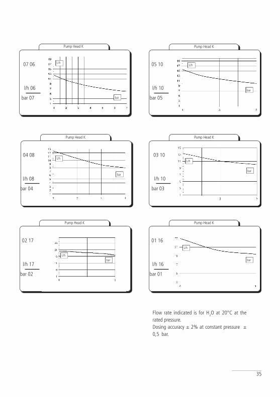
C Appendix. Delivery Curves
Pump Head J
20 01
l/h 01
bar 20bar
L/h
Pump Head K
18 02
l/h 02
bar 18bar
L/h
Pump Head K
15 04
l/h 04
bar 15
bar
L/h
Pump Head K
bar
L/h15 02
l/h 02
bar 15
Pump Head K
10 05
l/h 05
bar 10
Pump Head K
10 04
l/h 04
bar 10
bar
L/h
bar
L/h
Pump Head K
18 04
l/h 04
bar 18
bar
L/h
Pump Head K
10 10
l/h 10
bar 10
bar
L/h
35
Flow rate indicated is for H2O at 20°C at the rated pressure. Dosing accuracy ± 2% at constant pressure ± 0,5 bar.
Pump Head K
Pump Head K
bar
L/h05 10
l/h 10
bar 05
bar
L/h04 08
l/h 08
bar 04
Pump Head K
Pump Head K
bar
L/h
bar
L/h
03 10
l/h 10
bar 03
01 16
l/h 16
bar 01
07 06
l/h 06
bar 07 bar
L/h
Pump Head K
Pump Head K
02 17
l/h 17
bar 02
L/hbar
36
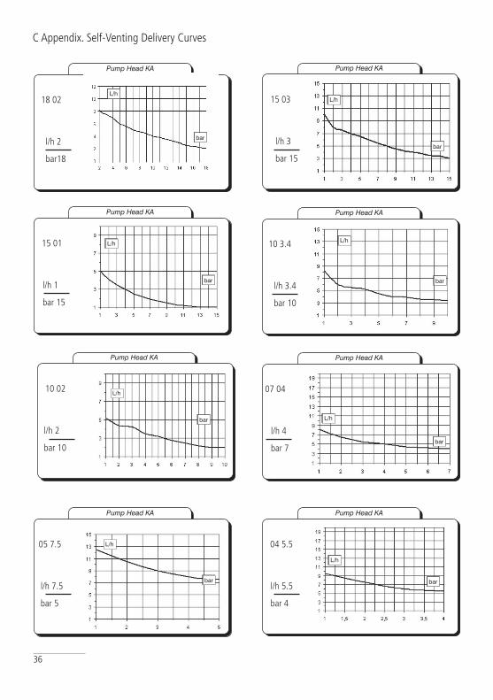
C Appendix. Self-Venting Delivery Curves
Pump Head KA
18 02
l/h 2
bar18
bar
L/h
Pump Head KA
15 03
l/h 3
bar 15bar
L/h
Pump Head KA
10 3.4
l/h 3.4
bar 10
bar
L/h
Pump Head KA
bar
L/h
07 04
l/h 4
bar 7
Pump Head KA
05 7.5
l/h 7.5
bar 5
Pump Head KA
04 5.5
l/h 5.5
bar 4
bar
L/h
bar
L/h
Pump Head KA
15 01
l/h 1
bar 15
bar
L/h
Pump Head KA
10 02
l/h 2
bar 10
bar
L/h
37
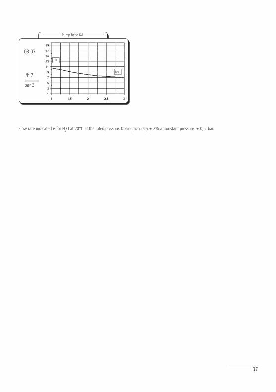
Flow rate indicated is for H2O at 20°C at the rated pressure. Dosing accuracy ± 2% at constant pressure ± 0,5 bar.
bar
L/h
Pump head KA
bar 3
03 07
l/h 7

38
D Appendix. Dimensions
DIMENSIONS
mm inch
A 106.96 4.21
B 210.44 8.28
C 199.44 7.85
D 114.50 4.50
E 187.96 7.40
F 97.00 3.81
G 106.96 4.21
H 125.47 4.93
L 50.00 1.96
M 201.00 7.91
39
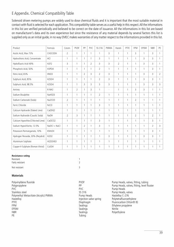
Solenoid driven metering pumps are widely used to dose chemical fluids and it is important that the most suitable material in contact with fluid is selected for each application. This compatibility table serves as a useful help in this respect. All the informations in this list are verified periodically and believed to be correct on the date of issuance. All the informations in this list are based on manufacturer’s data and its own experience but since the resistance of any material depends by several factors this list is supplied only as an initial guide, in no way EMEC makes warranties of any matter respect to the informations provided in this list.
Resistance rating Resistant 1 Fairly resistant 2
Not resistant 3
Materials Polyvinyldene fluoride PVDF Pump Heads, valves, fitting, tubing Polypropylene PP Pump Heads, valves, fitting, level floater PVC PVC Pump Heads Stainless steel SS 316 Pump Heads, valves Polymethyl Metacrilate (Acrylic) PMMA Pump Heads Hastelloy C-276 Hastelloy Injection valve spring Polytetrafluoroethylene PTFE Diaphragm Fluorocarbon (Viton® B) FPM Sealings Ethylene propylene EPDM Sealings Nitrile NBR Sealings Polyethylene PE Tubing
E Appendix. Chemical Compatibility Table
Product Formula Ceram. PVDF PP PVC SS 316 PMMA Hastel. PTFE FPM EPDM NBR PE
Acetic Acid, Max 75% CH3COOH 2 1 1 1 1 3 1 1 3 1 3 1
Hydrochloric Acid, Concentrate HCl 1 1 1 1 3 1 1 1 1 3 3 1
Hydrofluoric Acid 40% H2F2 3 1 1 2 3 3 2 1 1 3 3 1
Phosphoric Acid, 50% H3PO4 1 1 1 1 2 1 1 1 1 1 3 1
Nitric Acid, 65% HNO3 1 1 2 3 2 3 1 1 1 3 3 2
Sulphuric Acid, 85% H2SO4 1 1 1 1 2 3 1 1 1 3 3 1
Sulphuric Acid, 98.5% H2SO4 1 1 3 3 3 3 1 1 1 3 3 3
Amines R-NH2 1 2 1 3 1 - 1 1 3 3 1 1
Sodium Bisulphite NaHSO3 1 1 1 1 2 1 1 1 1 1 1 1
Sodium Carbonate (Soda) Na2CO3 2 1 1 1 1 1 1 1 2 1 1 1
Ferric Chloride FeCl3 1 1 1 1 3 1 1 1 1 1 1 1
Calcium Hydroxide (Slaked Lime) Ca(OH)2 1 1 1 1 1 1 1 1 1 1 1 1
Sodium Hydroxide (Caustic Soda) NaOH 2 3 1 1 1 1 1 1 2 1 2 1
Calcium Hypochlor.(Chlor.ted Lime) Ca(OCl)2 1 1 1 1 3 1 1 1 1 1 3 1
Sodium Hypochlorite, 12.5% NaOCl + NaCl 1 1 2 1 3 1 1 1 1 1 2 3
Potassium Permanganate, 10% KMnO4 1 1 1 1 1 1 1 1 1 1 3 1
Hydrogen Peroxide, 30% (Perydrol) H2O2 1 1 1 1 1 3 1 1 1 3 3 1
Aluminium Sulphate Al2(SO4)3 1 1 1 1 1 1 1 1 1 1 1 1
Copper-II-Sulphate (Roman Vitriol) CuSO4 1 1 1 1 1 1 1 1 1 1 1 1

40
F Appendix. Hoses resistance table
Hose features are very important for a reliable dosage. Every pump’s model is made to work in the best way using selected hoses according to pump’s capacity / model. Information reported here are intended for standard use only. For extended information ask to hose’s manufacturer.
41
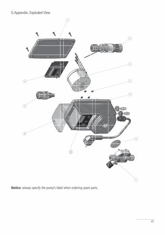
G Appendix. Exploded View
Notice: always specify the pump’s label when ordering spare parts.
1 1
2 2
3 3
4 4
5 5
6 6
7 7
8 8
AA
BB
CC
DD
EE
FF
Prog
etta
to d
aC
ontro
llato
da
Mod
ifica
to d
a, il
Dat
a
Ediz
ione
Fogl
io /Es
plos
o_vm
s-m
f
Mas
sim
o_F
28/0
1/20
11
00
Toll.
Gen
.
0.05
Mat
eria
le:
1 1
ESPL
OSO
PO
MPE
tipo
VM
S - M
F
12
46
53
11
8
7
910

42
PRODUCT SERVICE REPAIR FORM
SENDERCompany name ............................................................................................................................................ Address ................................................................................................................................................Phone no. ................................................................................................................................................Contact person.............................................................................................................................................
PRODUCT TYPE (see product label)DEVICE CODE .............................................................................................................................................. S/N (serial number).......................................................................................................................................
DESCRIPTION OF PROBLEM
MECHANICALWear parts .................................................................................................................................Brekage/other damages .............................................................................................................Corrosion ...................................................................................................................................Other .........................................................................................................................................
ELECTRICALConnections, connector, cables ...................................................................................................Operating controls (keyboard, display, etc.) .................................................................................Elettronics ..................................................................................................................................Other .........................................................................................................................................
LEAKSConnections ...............................................................................................................................Pump head ................................................................................................................................
NOT OR INADEqUATE FUNCTION/OTHER ................................................................................................................................................. ................................................................................................................................................. .................................................................................................................................................
MOD 7.5 B1 Q Ed. 1 - rev. 0 21/02/2012
OPERATING CONDITIONS
Location/installation description .................................................................................................................. ...................................................................................................................................................................Chemical ................................................................................................................................................Start-up (date) ............................................ Running time (approx. hours) ....................................................
REMOVE ALL THE LIQUID INTO THE PUMP HEAD AND DRy IT BEFORE PAcKAGING IN ITS ORIGINAL BOx.
I declare that the dosing pump is free of any hazardous chemical.
Signature of the compiler Company stamp
ENCLOSE THE PRESENT FORM TO THE DELIVERY NOTE
DATE ............................................
43
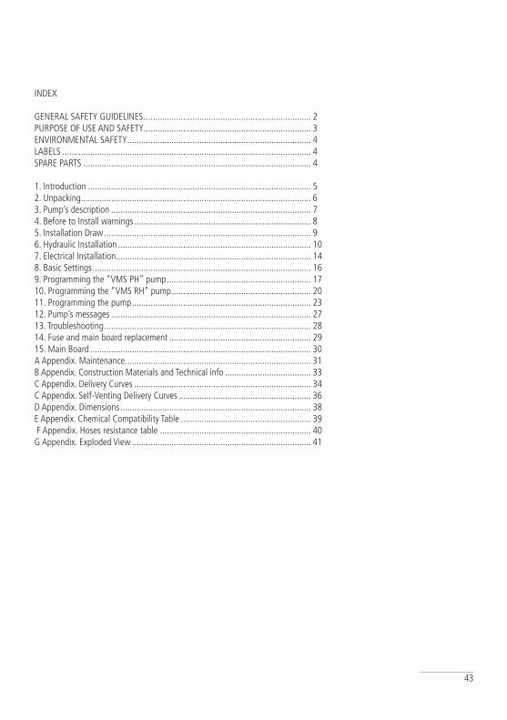
INDEX
GENERAL SAFETY GUIDELINES ........................................................................ 2PURPOSE OF USE AND SAFETY ........................................................................ 3ENVIRONMENTAL SAFETY ............................................................................... 4LABELS ........................................................................................................... 4SPARE PARTS .................................................................................................. 4
1. Introduction ................................................................................................ 52. Unpacking ................................................................................................... 63. Pump’s description ...................................................................................... 74. Before to Install warnings ............................................................................ 85. Installation Draw ......................................................................................... 96. Hydraulic Installation ................................................................................... 107. Electrical Installation.................................................................................... 148. Basic Settings .............................................................................................. 169. Programming the “VMS PH” pump .............................................................. 1710. Programming the “VMS RH” pump ............................................................ 2011. Programming the pump ............................................................................. 2312. Pump’s messages ...................................................................................... 2713. Troubleshooting ......................................................................................... 2814. Fuse and main board replacement ............................................................. 2915. Main Board ............................................................................................... 30A Appendix. Maintenance. ............................................................................... 31B Appendix. Construction Materials and Technical info ..................................... 33C Appendix. Delivery Curves ............................................................................ 34C Appendix. Self-Venting Delivery Curves ......................................................... 36D Appendix. Dimensions .................................................................................. 38E Appendix. Chemical Compatibility Table ........................................................ 39 F Appendix. Hoses resistance table ................................................................. 40G Appendix. Exploded View ............................................................................. 41

44
When dismantling a pump please separate material types and send them according to local recycling disposal requirements.We appreciate your efforts in supporting your local Recycle Environmental Program.
Working together we’ll form an active union to assure the world’s invaluable resources are conserved.