Embed Size (px)
Citation preview

1
VLSI Test Technology and
Reliability (ET4076)
Lecture 5
Combinational Circuit Test Generation (Chapter 7)
Said Hamdioui
Computer Engineering Lab
Delft University of Technology
2009-2010

VLSI Test Technology and Reliability, 2009-2010 CE Lab, TUDelft 2
Learning aims of today’s lecture
� Be able to
� Define the different types of ATPG (concept, advantages, disadvantages)
� Apply ATPG algorithms on combinational circuits
� Explain the difference between the different path sanitization ATPG algorithms (D, PODEM, FAN)

VLSI Test Technology and Reliability, 2009-2010 CE Lab, TUDelft 3
Contents
� Algorithms and representations� Structural vs. functional test
� Definition of ATPG
� Search spaces
� Algorithm completeness
� ATPG algebra
� Types of Algorithms
� Redundancy Identification
� Testing as a global problem
� ATPG algorithms� D-Calculus & D-Algorithm
� PODEM Algorithm
� FAN algorithm
� Advanced algorithms
� Test compaction

VLSI Test Technology and Reliability, 2009-2010 CE Lab, TUDelft 4
Functional vs. Structural ATPG
Adder with 129 inputs and 65 outputs
VLSI Test Technology and Reliability, 2009-2010 CE Lab, TUDelft 5
� Functional ATPG – generate complete set of tests for circuit input-output combinations
� 129 inputs, 65 outputs:
� 2129 = 680,564,733,841,876,926,926,749,214,863,536,422,912patterns
� Using 1 GHz ATE, would take 2.15 x 10²² years
=> Not practical
� Structural test:
� No redundant adder hardware, 64 bit slices
� Each with 27 faults (using fault equivalence)
� At most 64 x 27 = 1728 faults (at the most 1728 tests)
� Takes 0.000001728 s on 1 GHz ATE
� Designer gives small set of functional tests (~ 70% FC)
� Augment with structural tests to boost coverage to 98+ %
Functional vs. Structural (Continued)

VLSI Test Technology and Reliability, 2009-2010 CE Lab, TUDelft 6
Definitions
� ATPG: Automatic Test pattern generator � Operations on digital hardware:� Inject fault into circuit modeled in computer� Use various ways to activate and propagate fault effect through hardware to circuit output
� Output flips from expected to faulty signal
� Electron-beam (E-beam) test� Observes internal signals – “picture” of nodes charged to 0 and 1 in different colors
� No need to propagate the fault effect to the PO� Too expensive
� Scan design� Add test hardware to all FFs to make them a shift Register� Can shift state in, scan state out (test mode)� Widely used: makes sequential test combinational� Costs: 5 to 20% chip area, circuit delay, extra pin, longer testsequence

VLSI Test Technology and Reliability, 2009-2010 CE Lab, TUDelft 7
Search space abstractions
Binary Search tree
� The corresponding binary tree� Gives all possible input patterns
� Leaf: labeled with good output
� ATPG implicitly search the tree to find test pattern
� Worst case: complete examination� Exponential rise
� # of leaves: 2#PI

VLSI Test Technology and Reliability, 2009-2010 CE Lab, TUDelft 8
� Binary decision tree
� Follow path from root/source to sink node – product of literals along path gives Boolean value at sink
� Rightmost path: A B* C* = 1
� Leftmost path: A*B*C* = 0
� Problem: Size varies greatly with variable order
Search space abstractions
Binary decision tree

VLSI Test Technology and Reliability, 2009-2010 CE Lab, TUDelft 9
Algorithm Completeness� An algorithm is complete if it ultimately can search entire binary decision tree, if needed, to generate a test
� Completeness is important, otherwise ATPG may not achieve the required fault coverage
� Untestable fault – no test for it even after entire tree searched
� Thus circuit behaves correct even in the presence of the fault
� Combinational circuits only – untestable faults are redundant, showing the presence of unnecessary hardware

VLSI Test Technology and Reliability, 2009-2010 CE Lab, TUDelft 10
ATPG Algebra� Roth’s 5-Valued and Muth’s 9-Valued
� ATPG algebra: higher order Boolean set of notation to presents both good and failing circuit simultaneously
1XX/1F1
0XX/0F0
X11/XG1
X00/XG0
XXX/XX
111/11
000/00
100/1D*
011/0D
Failing machineGood machineMeaningSymbol
Roth’s Algebra
[5 values]
Muth’s additions
[Extended unknowns]

VLSI Test Technology and Reliability, 2009-2010 CE Lab, TUDelft 11
Roth’s and Muth’s Higher-Order Algebras
� Represent two machines, which are simulated simultaneously by a computer program:
� Good circuit machine (1st value)
� Bad circuit machine (2nd value)
� Better to represent both in the algebra:
� Need only 1 pass of ATPG to solve both
� Needed for complete ATPG:
� Combinational: Roth Algebra, Multi-path sensitization,
� Sequential: Muth Algebra -- good and bad machines may have different initial values due to fault
ATPG Algebra

VLSI Test Technology and Reliability, 2009-2010 CE Lab, TUDelft 12
Type of algorithms
� Exhaustive
� Expensive
� Not practical, unless circuit partitioned
� Random-Pattern Generation
� Easy to implement
� Does not realize higher fault coverage
� Path Sensitization Method
� Preferred ATPG method

VLSI Test Technology and Reliability, 2009-2010 CE Lab, TUDelft 13
Type of algorithms…. Exhaustive
� For n-input circuit, generate all 2n input patterns
� Infeasible, unless circuit is partitioned into cones of logic, with ≤ 15 inputs
� Perform exhaustive ATPG for each cone
� Misses faults that require specific activation patterns for multiple cones to be tested
VLSI Test Technology and Reliability, 2009-2010 CE Lab, TUDelft 14
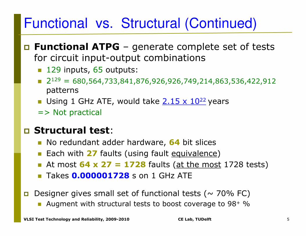
� Flow chart for method
� Use to get tests for 60-80% of faults, then switch to D-algorithm or other ATPG for rest
Type of algorithms….Random-Pattern Generation

VLSI Test Technology and Reliability, 2009-2010 CE Lab, TUDelft 15
Type of algorithms…… Path Sensitization Method
� Is the preferred ATPG method
� Approach based on three steps1. Fault sensitization
� Line SAF is activated by forcing it to an opposite value from the fault value
� Also known as Fault activation, fault excitation
2. Fault propagation� Fault effect is to be propagated through one or more paths to
PO
� Also known as path sensitization
3. Line justification� Justify the sensitized fault by setting the PI of the circuits
� Steps 2 and 3 may find a conflict� ATPG has to backup or backtrack
� i.e., discard previously made signal assignment and make an alternative assignment

VLSI Test Technology and Reliability, 2009-2010 CE Lab, TUDelft 16
Type of algorithms…… Path Sensitization Method
� Example:� Fault sensitization: set B to 1
1111

VLSI Test Technology and Reliability, 2009-2010 CE Lab, TUDelft 17
Type of algorithms…… Path Sensitization Method
� Example:� Fault sensitization: set B to 1
� Fault propagation: Try path f – h – k – L
� Line justification: There is no way to justify the 1 on i
⇒ Conflict
⇒ Backtrack
11110000
DDDD
DDDD1111
1111
1111
DDDDDDDD

VLSI Test Technology and Reliability, 2009-2010 CE Lab, TUDelft 18
Type of algorithms…… Path Sensitization Method
� Example:� Fault sensitization: set B to 1
� Fault propagation:
� Try simultaneous paths f – h – k – L and g – i – j – k – L
� Blocked at k because D-frontier (D or D*) disappears
1111D*D*D*D*
DDDD
DDDD1111
1111
1111
DDDD DDDD

VLSI Test Technology and Reliability, 2009-2010 CE Lab, TUDelft 19
Type of algorithms…… Path Sensitization Method
� Example:� Fault sensitization: set B to 1
� Fault propagation: Try path g – i – j – k – L
� Line justification: set A to 0
=> Test found and fault detected
1111D*D*D*D*
DDDD
00000000
1111
D*D*D*D*D*D*D*D*
DDDD DDDD

VLSI Test Technology and Reliability, 2009-2010 CE Lab, TUDelft 20
ATPG Computational Complexity
� Ibarra and Sahni analysis [1975] – NPNP--CompleteComplete� No polynomial expression found for compute time, presumed to be exponential
� Worst case:
� no_pi inputs, 2no_pi input combinations
� no_ff flip-flops, 4no_ff initial flip-flop states� (good machine 0 or 1 x bad machine 0 or 1)
� work to forward simulate or reverse simulate all logic gates n rises proportional with n
� Complexity: O(n x 2no_pi x 4no_ff)

VLSI Test Technology and Reliability, 2009-2010 CE Lab, TUDelft 21
ATPG Computational Complexity (Cnt)
� History ATPG
� Improve heuristic algorithms & procedures to:
� Find all necessary signal assignments as early as possible
� Search as little as possible of the decision space
� Worst case complexity: O(n x 2no_pi x 4no_ff)
� Fault simulation
� For combinational circuits: O(n2)
� For sequential circuits: estimated between O(n2) and O(n3)
� Based on empirical measurements
⇒ whenever possible use fault simulation to avoid ATPG computations
E.g.,
- Use RPG and fault simulation to get tests
- Use ATPG for hard-to-test faults

VLSI Test Technology and Reliability, 2009-2010 CE Lab, TUDelft 22
ATPG Computational Complexity* (Cnt)
ATPG for analog:
Analog Fault Modeling Impractical for Logic ATPG
� Problems with modeling actual defects in analog circuits
� Huge # of different possible analog faults in digital circuit
� Exponential complexity of ATPG algorithm – a 20 flip-flop circuit can take days of computing
� Cannot afford to go to a lower-level model
� Most test-pattern generators for digital circuits cannot even model at the transistor switch level
� More complex
� (see textbook for 5 examples of switch-level ATPG)

VLSI Test Technology and Reliability, 2009-2010 CE Lab, TUDelft 23
Redundancy identification… Untestable faults(1)
� Combinational ATPG can find redundant
(unnecessary) hardware
� Untestable faults in combinational circuits indicates
redundant hardware
� Fault Test
a sa1, b sa0 A = 1
a sa0, b sa1 A = 0
� All faults are testable
� Therefore, these faults are not redundant

VLSI Test Technology and Reliability, 2009-2010 CE Lab, TUDelft 24
Redundancy identification… Untestable faults(2)
Test fault: s-a-0 on line d
� Set A & B to 1
� However, E will be 1
� Fault cannot be propagated to the output
=> Untestable fault
=> Redundant Hardware
� Remove the redundant hardware
� d always 0: ground it permanently
� Remove OR gate and replace with a wire
� And discard AND gate and input A

VLSI Test Technology and Reliability, 2009-2010 CE Lab, TUDelft 25
� Test fault q s-a-1� Fault sensitization: set q to 0� Fault propagation: set A to 1 and s to 1� Line justification: set B to 0 and C to 0⇒ Conflict at sNo other possible alternative assignments⇒ Redundant fault
Redundancy identification …. Untestable faults(3)

VLSI Test Technology and Reliability, 2009-2010 CE Lab, TUDelft 26
� f s-a-0 tested when fault q s-a-1 not there
� Fault sensitization: set f to 1
� Fault propagation (via felqz): set d to 1, m to 0, s to 1, n to 1
� Line justification: set A to 1, B to 1 and C to 0
⇒ Fault detected at Z
Redundancy identification …. Fault masking (1)

VLSI Test Technology and Reliability, 2009-2010 CE Lab, TUDelft 27
� f s-a-0 tested when fault q s-a-1 also present
� Fault sensitization: set f to 1
� Fault propagation (via felqz): set d to 1, m to 0, …
� Blocked by q s-a-1 => Fault can NOT be detected
⇒ q s-a-1 (redundant) masks f s-a0
Redundancy identification …. Fault masking (2)

VLSI Test Technology and Reliability, 2009-2010 CE Lab, TUDelft 28
Eliminates hazards in circuit output
� OUT0=A.B+A*.C (+B.C)
� B.C is added to prevent hazards (when A 0 � 1)
� Redundant fault s-a-0 on line e
� No effect on the function
� But masks any testable fault using line e to propagate to OUT
� Additional area and power due to redundancy
Redundancy identification ……… Hazards
VLSI Test Technology and Reliability, 2009-2010 CE Lab, TUDelft 29
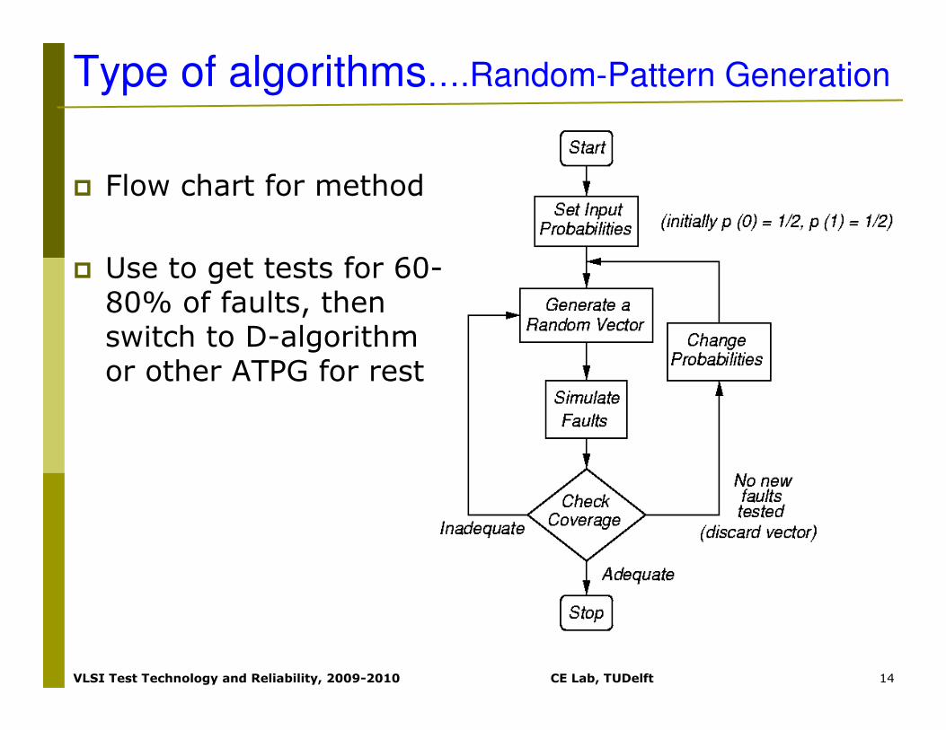
� Redundancy impacts:
� Performance
� Power consumption
� Area overhead
� Reliability
� A redundant fault can mask the presence of other testable faults
� Unwanted in systems critical to human safety or wealth!!
� How to deal with it?
� Impossible to do that manually (e.g., Millions of gates)
� Commercial tools
� Synthesis moderately-sized designs to irredundant hardware
� Big designs have to be partitioned before synthesis
� May introduce redundant hardware
� ATPG is one of the best ways to find this redundancy
Redundancy identification ………Impact

VLSI Test Technology and Reliability, 2009-2010 CE Lab, TUDelft 30
Testing as a global problem
� Testing is a global problem
� Combination of fully testable modules in a logic circuit are
� Not necessary fully testable
� May be not be testable with the same patterns that would test the modules individually
Example
� Module 1
� Requires AB= 11 for d s-a-0
� The test cannot be used for the
entire circuit
Module 1

VLSI Test Technology and Reliability, 2009-2010 CE Lab, TUDelft 31
ATPG algorithms
� Definitions
� D-Algorithm (Roth) -- 1966� D-cubes
� Bridging faults
� Logic gate function change faults
� PODEM (Goel) -- 1981� X-Path-Check
� Backtracing
� Summary

VLSI Test Technology and Reliability, 2009-2010 CE Lab, TUDelft 32
ATPG algorithms… History & Speedups
199725057Tafertshofer et al.
1995485Recursive learning
19933005 ATPG SystemTRAN
19918765 ATPG SystemEST
19902189 ATPG SystemWaicukauski et al.
19881574 ATPG SystemSOCRATES
1987292TOPS
198323FAN
19817PODEM
19661D-ALG
YearEst. speedup
over D-ALG
Algorithm

VLSI Test Technology and Reliability, 2009-2010 CE Lab, TUDelft 33
Fault Cone and D-frontier
� Fault Cone: Set of hardware affected by fault
� D-frontier: Set of all gates with D or D* at inputs and X at the output
Fault Cone
D-frontier
ATPG algorithms………Definitions (1)

VLSI Test Technology and Reliability, 2009-2010 CE Lab, TUDelft 34
ATPG algorithms………Definitions(2)
Forward Implication
� Results in logic gate inputs that are significantly labeled so that output is uniquely determined
� Example:
� AND gate forward implication table:
Forward

VLSI Test Technology and Reliability, 2009-2010 CE Lab, TUDelft 35
ATPG algorithms………Definitions(3)
Backward Implication
� Unique determination of all gate inputs when the gate output and some of the inputs are given
� Example
VLSI Test Technology and Reliability, 2009-2010 CE Lab, TUDelft 36
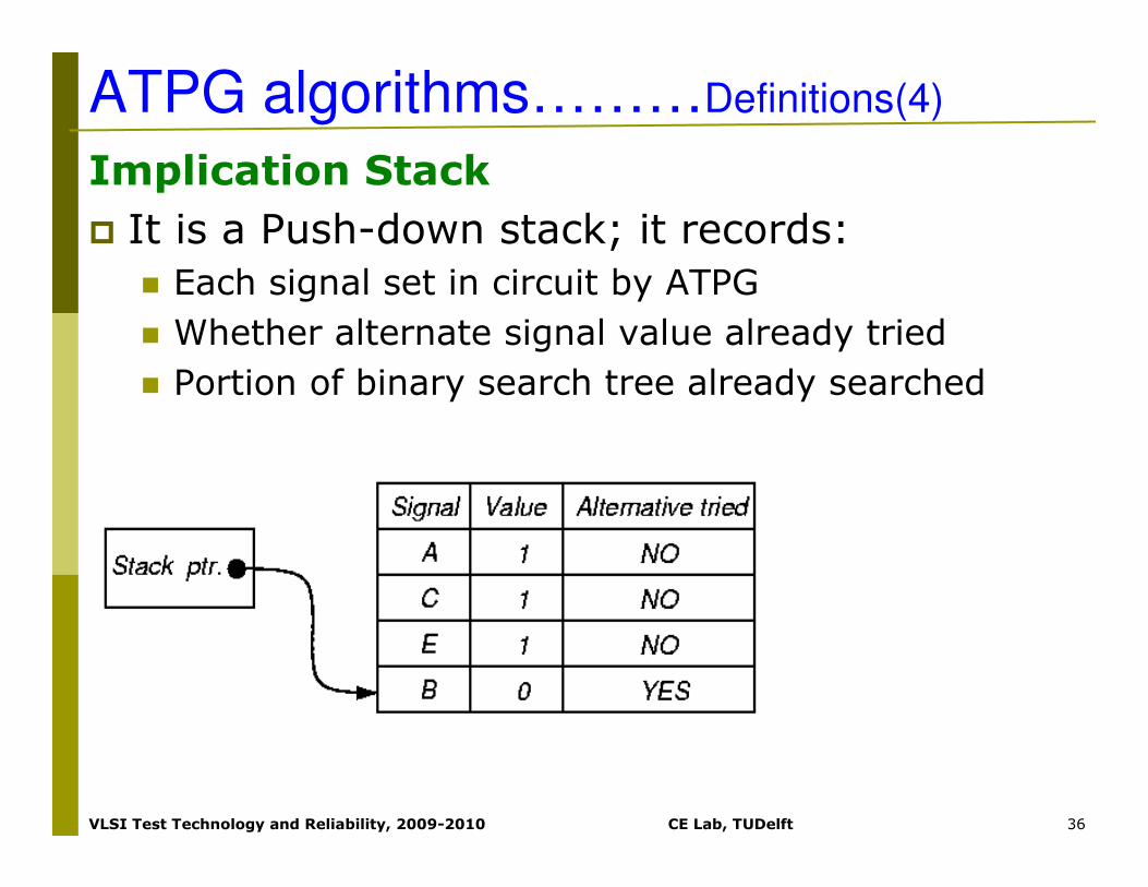
Implication Stack
� It is a Push-down stack; it records:
� Each signal set in circuit by ATPG
� Whether alternate signal value already tried
� Portion of binary search tree already searched
ATPG algorithms………Definitions(4)

VLSI Test Technology and Reliability, 2009-2010 CE Lab, TUDelft 37
0
1
0 0
0
0
0 11 1
1
E
F
BB
F F
1
UnexploredPresent AssignmentSearched and Infeasible
� Implication Stack after backtrack
ATPG algorithms………Definitions(5)

VLSI Test Technology and Reliability, 2009-2010 CE Lab, TUDelft 38
� ATPG Objective
� Desired signal value to be achieved
� Guides it away from infeasible/hard solutions
� Backtrace
� Determines which primary input and value to set to achieve objective
� Use testability measures
ATPG algorithms………Definitions(6)
Objective
Backtrace
Easiest one to set

VLSI Test Technology and Reliability, 2009-2010 CE Lab, TUDelft 39
ATPG algorithms………Definitions(7)
Branch-and-Bound Search
� Efficiently searches binary search tree
� Branching – At each tree level, selects which input variable to set to what value
� Bounding – Avoids exploring large tree portions by artificially restricting search decision choices
� Complete exploration is impractical
� Uses heuristics

VLSI Test Technology and Reliability, 2009-2010 CE Lab, TUDelft 40
� Fundamental concepts invented:
� First complete ATPG algorithm
� D-Cube
� D-Calculus
� Implications – forward and backward
� Implication stack
� Backtrack
� Test Search Space
D-Algorithm….. Roth IBM (1966)

VLSI Test Technology and Reliability, 2009-2010 CE Lab, TUDelft 41
� Singular Cover:
Minimal set of logic signal assignments to show essential prime implicants of Karnaugh map
GateAND123
InputsA0X1
BX01
Outputd001
GateNOR123
Inputsd1X0
eX10
OutputF001
D-Algorithm………….. Definitions(1)

VLSI Test Technology and Reliability, 2009-2010 CE Lab, TUDelft 42
D-Algorithm………….. Definitions(2)
D-Cube: Collapsed truth table entry to
characterize logic block
� Use Roth’s 5-valued algebra
� Can change all D’s to D*’s and D*’s to D’s (do both)
� Example: AND gate propagation :
Combine rows 3 (good) & 1(faulty)
Reverse inputs
And two cubes
Interchange D and D*
AD
1
D
D*
1
D*
B1
D
D
D*
D*
1
dD
D
D
D*
D*
D*

VLSI Test Technology and Reliability, 2009-2010 CE Lab, TUDelft 43
D-Cube Operation of D-Intersection� D-intersection: 0 ∩∩∩∩ 0 = 0 ∩∩∩∩ X = X ∩∩∩∩ 0 = 0
1 ∩∩∩∩ 1 = 1 ∩∩∩∩ X = X ∩∩∩∩ 1 = 1
X ∩∩∩∩ X = X
� ψψψψ – undefined (same as φφφφ)
� If both µµµµ and λλλλ occur, then cubes incompatible
� If only µµµµ occur, then D∩D=D and D*∩D*=D*
� If only λλλλ occur, then inverse D and D* in second cube
� D-containment:
Cube a contains
Cube b if b is a
subset of a
0000
1111
XXXX
DDDD
D*D*D*D*
0000
0000
φφφφ0000
ψψψψψψψψ
1111
φφφφ1111
1111
ψψψψψψψψ
XXXX
0000
1111
XXXX
DDDD
D*D*D*D*
DDDD
ψψψψψψψψDDDD
µµµµλλλλ
D*D*D*D*
ψψψψψψψψD*D*D*D*
λλλλµµµµ
∩
D-Algorithm………….. Definitions(3)

VLSI Test Technology and Reliability, 2009-2010 CE Lab, TUDelft 44
D-Algorithm………….. Definitions(4)
Primitive D-Cube of Failure � Models circuit faults:
� Stuck-at-0� Stuck-at-1� Bridging fault (short circuit)� Arbitrary change in logic function
� AND Output sa0: “1 1 D”� AND Output sa1: “0 X D*” and “X 0 D*”� Wire sa0: “D”; Wire sa1: “D*”;
Test cube:Refers to the set of PI, intermediate, and PO circuit signals that are set to get a test for the fault
Propagation D-cube: models conditions under which fault effect propagates through gate

VLSI Test Technology and Reliability, 2009-2010 CE Lab, TUDelft 45
D-Algorithm………….. Definitions(5)
Implication Procedure
1. Model fault with appropriate primitive D-cube of failure (PDF)
2. Select propagation D-cubes to propagate fault effect to a circuit output (D-drive procedure)
3. Select singular cover cubes to justify internal circuit signals (Consistency procedure)
� If Cube intersection fail, back up to the last decision point and select an alternative cube
� Put signal assignments in test cube
� Regrettably, cubes are selected very arbitrarily by D-ALG

VLSI Test Technology and Reliability, 2009-2010 CE Lab, TUDelft 46
D-Algorithm ……..Top Level
1. Number all circuit lines in increasing level order from PIs to POs;
2. Select a primitive D-cube of the fault to be the test cube;
� Put logic outputs with inputs labeled as D (D*) onto the D-frontier;
//[provoke the fault and D-cube]
3. D-drive (); //[Propagate D or D* to PO]
4. Consistency (); //[Tracking backwards to PI]
5. return ();

VLSI Test Technology and Reliability, 2009-2010 CE Lab, TUDelft 47
D-Algorithm ………….D-drive
while (untried fault effects on D-frontier)select next untried D-frontier gate for propagation;
while (untried fault effect fanouts exist)
select next untried fault effect fanout;
generate next untried propagation D-cube;
D-intersect selected cube with test cube;
if (intersection fails or is undefined) continue;
if (all propagation D-cubes tried & failed) break;
if (intersection succeeded)
add propagation D-cube to test cube -- recreate D-frontier;
Find all forward & backward implications of assignment;
save D-frontier, algorithm state, test cube, fanouts, fault;
break;
else if (intersection fails & D and D* in test cube) Backtrack ();
else if (intersection fails) break;
if (all fault effects unpropagatable) Backtrack ();

VLSI Test Technology and Reliability, 2009-2010 CE Lab, TUDelft 48
D-Algorithm……Consistencyg = coordinates of test cube with 1’s & 0’s;
if (g is only PIs) fault testable & stop;
for (each unjustified signal in g)Select highest # unjustified signal z in g, not a PI;
if (inputs to gate z are both D and D*) break;
while (untried singular covers of gate z)select next untried singular cover;
if (no more singular covers)
If (no more stack choices) fault untestable & stop;
else if (untried alternatives in Consistency)
pop implication stack -- try alternate assignment;else
Backtrack ();
D-drive ();If (singular cover D-intersects with z) delete z from g, add inputs to singular cover to g, find all forward and backward implications of new assignment, and break;
If (intersection fails) mark singular cover as failed;

VLSI Test Technology and Reliability, 2009-2010 CE Lab, TUDelft 49
D-Algorithm…… Backtrack
if (PO exists with fault effect) Consistency ();
else pop prior implication stack setting to try alternate assignment;
if (no untried choices in implication stack)
fault untestable & stop;
else return;

VLSI Test Technology and Reliability, 2009-2010 CE Lab, TUDelft 50
Inputs
a0
0
0
0
1
1
1
1
b0
0
1
1
0
0
1
1
c0
1
0
1
0
1
0
1
Output
F0
0
0
1
0
0
0
0
D-Algorithm…….. Example1(1)
� Circuit Example 7.1 and Truth Table

VLSI Test Technology and Reliability, 2009-2010 CE Lab, TUDelft 51
� Singular cover – Used for justifying lines
� Propagation D-cubes –Conditions under which difference between good/failing machines propagates
A10
D1D
B1
010
1DDD1D
C
1
0
1DD
d100
10
DDD
D0D
e
0111
0
D*D*D*0DD
F
001
D*D*D*
D-Algorithm…….. Example1(2)

VLSI Test Technology and Reliability, 2009-2010 CE Lab, TUDelft 52
Step
1
2
3
A1
B1
1
C
1
dD
D
e
0
0
F
D*
Cube type
PDF of AND gate
Prop. D-cube for NOR
Singular Cover of NAND
� Steps for Fault d sa0
D-Algorithm…….. Example1(3)

VLSI Test Technology and Reliability, 2009-2010 CE Lab, TUDelft 53
� Example 7.2 Fault A sa0
� Step 1: Select a primitive D-cube of the fault - Set A = 1
DDDD1111 DDDD
D-Algorithm…….. Example2(1)

VLSI Test Technology and Reliability, 2009-2010 CE Lab, TUDelft 54
DDDD1111
0000
DDDD
� Step 2: D-Drive – Set f = 0
DDDD
D-Algorithm…….. Example2(2)

VLSI Test Technology and Reliability, 2009-2010 CE Lab, TUDelft 55
DDDD1111
0000
DDDD
� Step 3: D-Drive – Set k = 1
DDDD
1111
DDDD
D-Algorithm…….. Example2(3)

VLSI Test Technology and Reliability, 2009-2010 CE Lab, TUDelft 56
DDDD1111
0000
DDDD
� Step 4: Consistency – Set g = 1
DDDD
1111
DDDD
1111
D-Algorithm…….. Example2(4)
VLSI Test Technology and Reliability, 2009-2010 CE Lab, TUDelft 57
DDDD1111
0000
DDDD
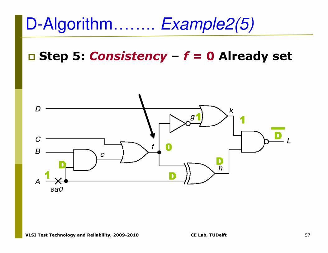
� Step 5: Consistency – f = 0 Already set
DDDD
1111
DDDD
1111
D-Algorithm…….. Example2(5)

VLSI Test Technology and Reliability, 2009-2010 CE Lab, TUDelft 58
DDDD1111
0000
DDDD
� Step 6: Consistency – Set c=0, Set e=0
DDDD
1111
DDDD
1111
0000
0000
D-Algorithm…….. Example2(6)

VLSI Test Technology and Reliability, 2009-2010 CE Lab, TUDelft 59
DDDD1111
0000
XXXX
DDDD
� Step 7: Consistency – Set B = 0
� No more line to justify: pattern found
DDDD
1111
DDDD
1111
0000
0000
0000
� Test cube: A, B, C, D, e, f, g, h, k, L
� TC7=D00X001D1D*
D-Algorithm…….. Example2(7)

VLSI Test Technology and Reliability, 2009-2010 CE Lab, TUDelft 60
PODEM…………….Motivation
� IBM introduced semiconductor DRAM memory into its mainframes – late 1970’s
� Memory had error correction and translation circuits – improved reliability
� D-ALG unable to test these circuits
�Search too undirected
�Large XOR-gate trees
�Must set all external inputs to define output
� Needed a better ATPG tool

VLSI Test Technology and Reliability, 2009-2010 CE Lab, TUDelft 61
PODEM………Goel IBM (1981)
� New concepts introduced:
� Expand binary decision tree only around primary inputs
�Reduction from 2n to 2#PI (n: # of logic gates)
� Use X-PATH-CHECK to test whether
D-frontier still there
� Objectives: bring ATPG closer to
propagating D (D*) to PO
� Backtracing
�Use # of levels or CC measures to assign PI objectives

VLSI Test Technology and Reliability, 2009-2010 CE Lab, TUDelft 62
PODEM……. High-Level Flow
1.Assign binary value to unassigned PI
2.Determine implications of all PIs
3.Test Generated? If so, done.
4.Test possible with additional assigned PIs? If maybe, go to Step 1
5.Is there untried combination of values on assigned PIs? If not, exit: untestable fault
6.Set untried combination of values on assigned PIs using objectives and backtrace. Then, go to Step 2

VLSI Test Technology and Reliability, 2009-2010 CE Lab, TUDelft 63
� Example 7.3
� Step 1: Select path s – Y for fault propagation; not s-u-v-Z (level distance from PO is 1 versus 2)
sa1
PODEM……………. Example(1)

VLSI Test Technology and Reliability, 2009-2010 CE Lab, TUDelft 64
Step 2:
� Initial objective: Set r to 1 to sensitize fault
1111
sa1
PODEM……………. Example(2)

VLSI Test Technology and Reliability, 2009-2010 CE Lab, TUDelft 65
PODEM……………. Example(3)
� Step 3: Backtrace from r
=> Intermediate objectives: Set n to 0, m to 0, g to 0 and d to 0
1111
sa1

VLSI Test Technology and Reliability, 2009-2010 CE Lab, TUDelft 66
PODEM……………. Example(4)
� Step 4: Set A = 0 in implication stack
1111
0000
sa1

VLSI Test Technology and Reliability, 2009-2010 CE Lab, TUDelft 67
PODEM……………. Example(5)
� Step 5: Forward implications: d = 0, X = 1
� Does not define r (s-a-1)
1111
sa1
00000000
1111

VLSI Test Technology and Reliability, 2009-2010 CE Lab, TUDelft 68
PODEM……………. Example(6)
� Step 6: Initial objective: set r to 1
1111
sa1
00000000
1111

VLSI Test Technology and Reliability, 2009-2010 CE Lab, TUDelft 69
PODEM……………. Example(7)
� Step 7: Backtrace from r again
1111
sa1
00000000
1111

VLSI Test Technology and Reliability, 2009-2010 CE Lab, TUDelft 70
PODEM……………. Example(8)
� Step 8: Set B to 1.
� Implications in stack: A = 0, B = 1
1111
sa1
00000000
1111
1111

VLSI Test Technology and Reliability, 2009-2010 CE Lab, TUDelft 71
D*D*D*D*
PODEM……………. Example(9)
� Step 9: Forward implications: k=1, m=0, r=1,
q=1, Y=1, s=D*, u=D*, v*=D, Z=1
1111
sa1
1111
0000
1111
1111
D*D*D*D*
D*D*D*D*1111
0000
1111
0000
1111

VLSI Test Technology and Reliability, 2009-2010 CE Lab, TUDelft 72
PODEM……………. Example(10)
� Step 10: X-PATH-CHECK shows paths s–Yand s–u–v–Z blocked (D-frontier disappeared)
1111
sa1
00000000
1111

VLSI Test Technology and Reliability, 2009-2010 CE Lab, TUDelft 73
PODEM……………. Example(11)
� Step11: Set B = 0 (alternate assignment)
1111
sa1
0000
0000

VLSI Test Technology and Reliability, 2009-2010 CE Lab, TUDelft 74
PODEM……………. Example(12)
1111sa1
00000000
1111
0000 1111
0000
1111
00001111
00001111
� Step 12: Forward implications: d=0, X=1, m=1, r=0, s=1, q=0, Y=1, v=0, Z=1. Fault not sensitized.

VLSI Test Technology and Reliability, 2009-2010 CE Lab, TUDelft 75
PODEM……………. Example(13)
� Step 13: Set A = 1 (alternate assignment)
� No implications possible -> Backtrace r
1111
sa1
1111

VLSI Test Technology and Reliability, 2009-2010 CE Lab, TUDelft 76
PODEM……………. Example(14)
� Step 14: Backtrace from r again
1111
sa1
1111

VLSI Test Technology and Reliability, 2009-2010 CE Lab, TUDelft 77
PODEM……………. Example(15)
� Step 15: Set B = 0. Implications in stack: A = 1, B = 0
1111
sa1
1111
0000

VLSI Test Technology and Reliability, 2009-2010 CE Lab, TUDelft 78
PODEM……………. Example(16)� Step 16: Forward implications: d=0, X=1, m=1,
r = 0. Conflict: fault not sensitized.
-> Backtrack
sa1
1111
0000
0000
0000
1111
1111
1111
1111
11110000
00001111

VLSI Test Technology and Reliability, 2009-2010 CE Lab, TUDelft 79
PODEM……………. Example(17)
� Step 17: Set B = 1 (alternate assignment)
1111
sa1
1111
1111

VLSI Test Technology and Reliability, 2009-2010 CE Lab, TUDelft 80
PODEM……………. Example(18)
� Step 18: Forward implications: d=1,
m=1, r=1, q=0, s=D*, v=D*, X=0, Y=D*
1111
sa1
1111
1111
1111
1111
0000
D*D*D*D*
0000
DDDD
D*D*D*D*
XXXX
D*D*D*D*

VLSI Test Technology and Reliability, 2009-2010 CE Lab, TUDelft 81
PODEM …………Algorithm
while (no fault effect at POs)if (xpathcheck (D-frontier)
(l, vl) = Objective (fault, vfault);
(pi, vpi) = Backtrace (l, vl);
Imply (pi, vpi);
if (PODEM (fault, vfault) == SUCCESS) return (SUCCESS);
(pi, vpi) = Backtrack ();
Imply (pi, vpi);
if (PODEM (fault, vfault) == SUCCESS) return (SUCCESS);
Imply (pi, “X”);
return (FAILURE);
else if (implication stack exhausted)
return (FAILURE);
else Backtrack ();
return (SUCCESS);

VLSI Test Technology and Reliability, 2009-2010 CE Lab, TUDelft 82
Summary classical ATPG algorithms
� D-ALG – First complete ATPG algorithm� D-Cube
� D-Calculus
� Implications – forward and backward
� Implication stack
� Backup
� PODEM� Expand decision tree only around PIs
� Use X-PATH-CHECK to see if D-frontier exists
� Objectives -- bring ATPG closer to getting
D (D*) to PO
� Backtracing
VLSI Test Technology and Reliability, 2009-2010 CE Lab, TUDelft 83
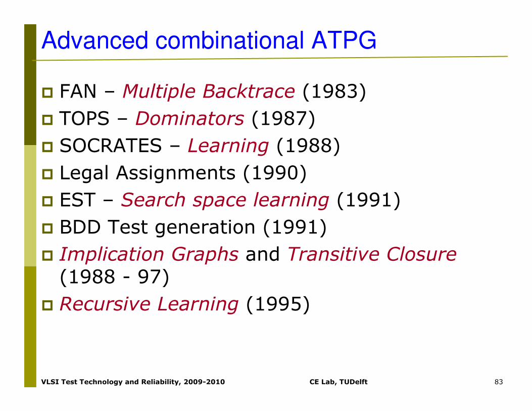
Advanced combinational ATPG
� FAN – Multiple Backtrace (1983)
� TOPS – Dominators (1987)
� SOCRATES – Learning (1988)
� Legal Assignments (1990)
� EST – Search space learning (1991)
� BDD Test generation (1991)
� Implication Graphs and Transitive Closure(1988 - 97)
� Recursive Learning (1995)

VLSI Test Technology and Reliability, 2009-2010 CE Lab, TUDelft 84
Advanced comb. ATPG…..….FAN
� FAN(1983)
� Further limit the ATPG space and accelerate Backtracing
� Use immediate implications of uniquely-determined signals
� Unique sensitization
� Assign values to headlines (instead of PI)
� Multiple Backtrace

VLSI Test Technology and Reliability, 2009-2010 CE Lab, TUDelft 85
Advanced comb. ATPG……..FAN
� Use immediate implications of uniquely-determined signals

VLSI Test Technology and Reliability, 2009-2010 CE Lab, TUDelft 86
Advanced comb. ATPG……..FAN
� Unique sensitization

VLSI Test Technology and Reliability, 2009-2010 CE Lab, TUDelft 87
Advanced comb. ATPG……..FAN
� Assign values to headlines (instead of PI)

VLSI Test Technology and Reliability, 2009-2010 CE Lab, TUDelft 88
Advanced comb. ATPG……..FAN
� Multiple Backtrace

VLSI Test Technology and Reliability, 2009-2010 CE Lab, TUDelft 89
Summary
� Structural vs. functional test
� Three types of ATPG algorithm
� Path sensitization algorithms are the preferred ATPG
� D-Algorithm, PODEM, FAN
� They use ATPG algebra
� Redundancy reduces the fault coverage
� Masking effect
� Reliability problems
� Testing is a global problem