Embed Size (px)
Citation preview
VLSI Digital Signal Processing Systems
Keshab K. Parhi
2Chap. 2
VLSI Digital Signal Processing Systems
• Textbook:– K.K. Parhi, VLSI Digital Signal Processing Systems: Design and
Implementation, John Wiley, 1999
• Buy Textbook:– http://www.bn.com– http://www.amazon.com– http://www.bestbookbuys.com
3Chap. 2
Chapter 1. Introduction to DSP Systems• Introduction (Read Sec. 1.1, 1.3)• Non-Terminating Programs Require Real-Time
Operations• Applications dictate different speed constraints
(e.g., voice, audio, cable modem, settop box,Gigabit ethernet, 3-D Graphics)
• Need to design Families of Architectures forspecified algorithm complexity and speedconstraints
• Representations of DSP Algorithms (Sec. 1.4)
4Chap. 2
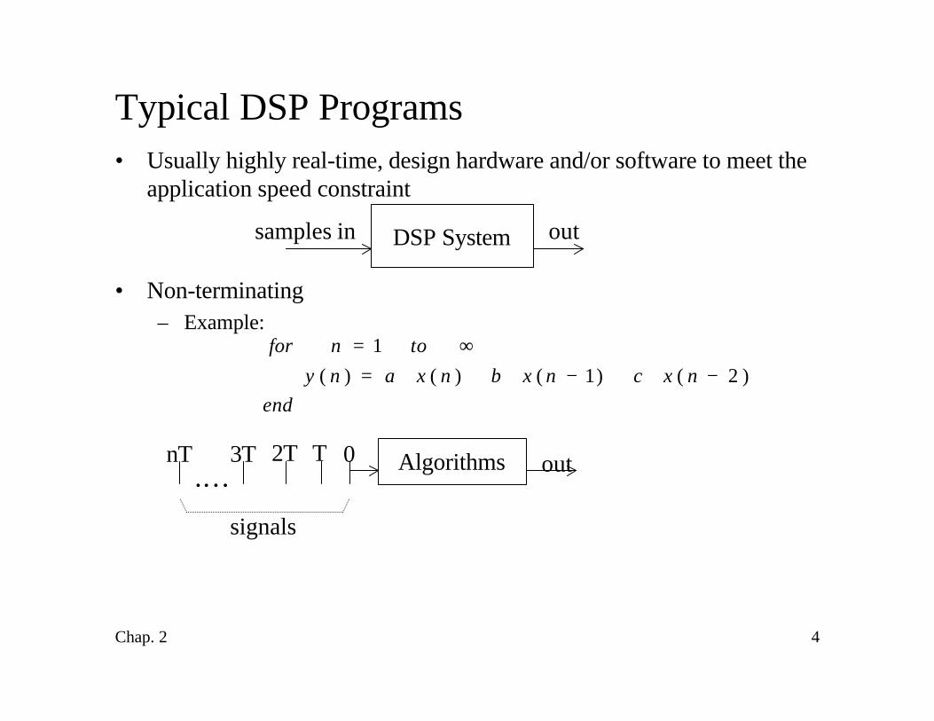
Typical DSP Programs• Usually highly real-time, design hardware and/or software to meet the
application speed constraint
• Non-terminating– Example:
DSP Systemsamples in out
Algorithms out.…
signals
0T2TnT 3T
endnxcnxbnxany
tonfor)2()1()()(
1−⋅+−⋅+⋅=
∞=
5Chap. 2
Area-Speed-Power Tradeoffs
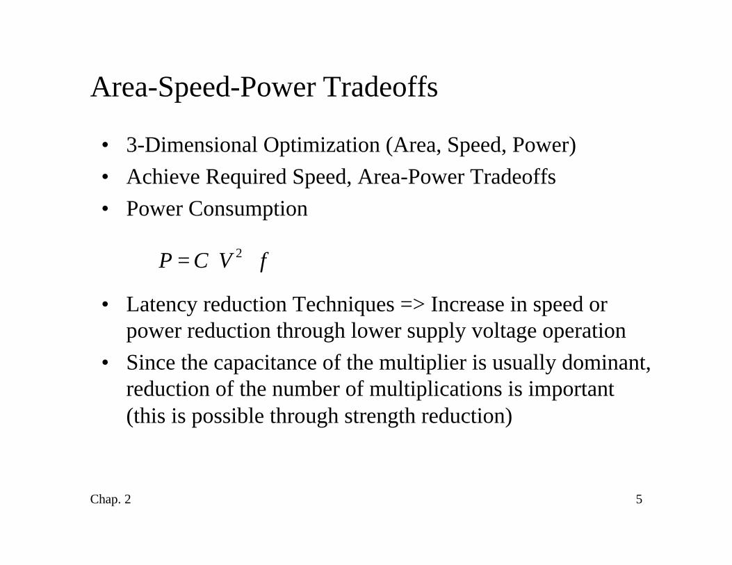
• 3-Dimensional Optimization (Area, Speed, Power)• Achieve Required Speed, Area-Power Tradeoffs• Power Consumption
• Latency reduction Techniques => Increase in speed orpower reduction through lower supply voltage operation
• Since the capacitance of the multiplier is usually dominant,reduction of the number of multiplications is important(this is possible through strength reduction)
fVCP ⋅⋅= 2
6Chap. 2
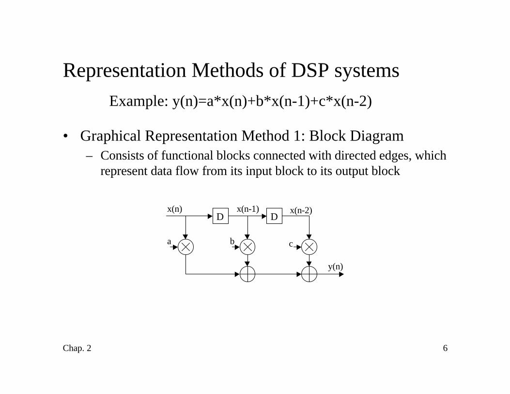
Representation Methods of DSP systemsExample: y(n)=a*x(n)+b*x(n-1)+c*x(n-2)
• Graphical Representation Method 1: Block Diagram– Consists of functional blocks connected with directed edges, which
represent data flow from its input block to its output block
DD
a b c
x(n)
y(n)
x(n-2)x(n-1)
7Chap. 2
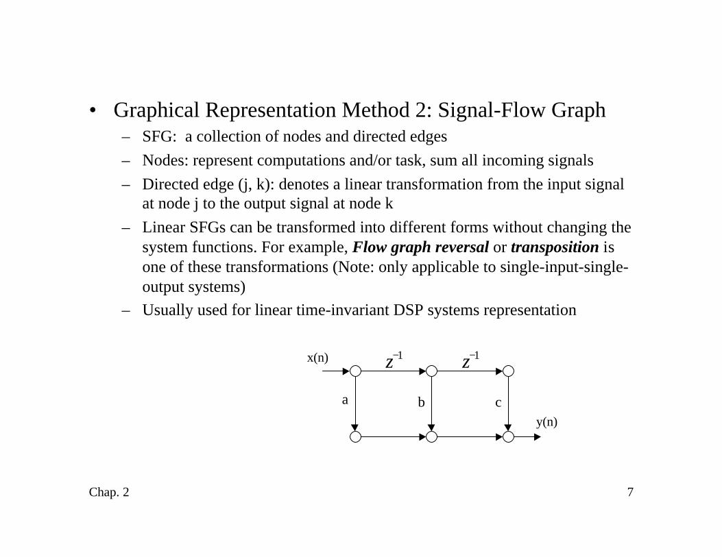
• Graphical Representation Method 2: Signal-Flow Graph– SFG: a collection of nodes and directed edges– Nodes: represent computations and/or task, sum all incoming signals– Directed edge (j, k): denotes a linear transformation from the input signal
at node j to the output signal at node k– Linear SFGs can be transformed into different forms without changing the
system functions. For example, Flow graph reversal or transposition isone of these transformations (Note: only applicable to single-input-single-output systems)
– Usually used for linear time-invariant DSP systems representation
x(n)
y(n)
a b c
1−z 1−z
8Chap. 2
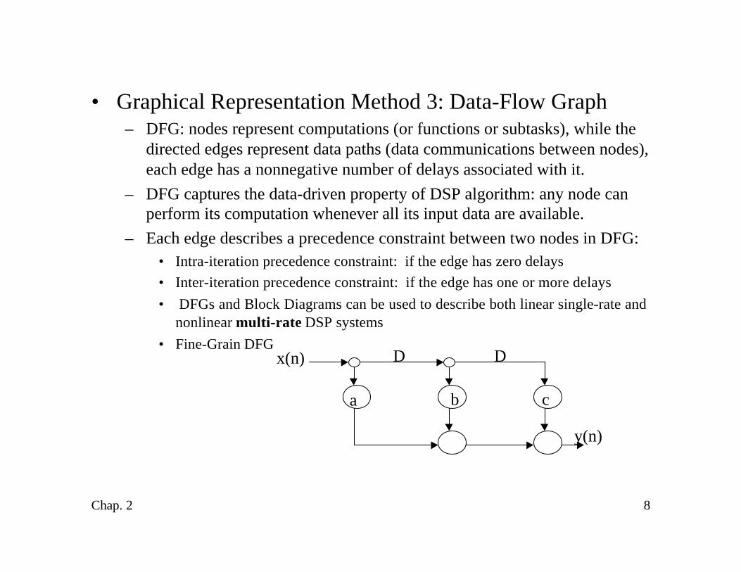
• Graphical Representation Method 3: Data-Flow Graph– DFG: nodes represent computations (or functions or subtasks), while the
directed edges represent data paths (data communications between nodes),each edge has a nonnegative number of delays associated with it.
– DFG captures the data-driven property of DSP algorithm: any node canperform its computation whenever all its input data are available.
– Each edge describes a precedence constraint between two nodes in DFG:• Intra-iteration precedence constraint: if the edge has zero delays• Inter-iteration precedence constraint: if the edge has one or more delays• DFGs and Block Diagrams can be used to describe both linear single-rate and
nonlinear multi-rate DSP systems• Fine-Grain DFG
x(n)
y(n)
b ca
D D
9Chap. 2
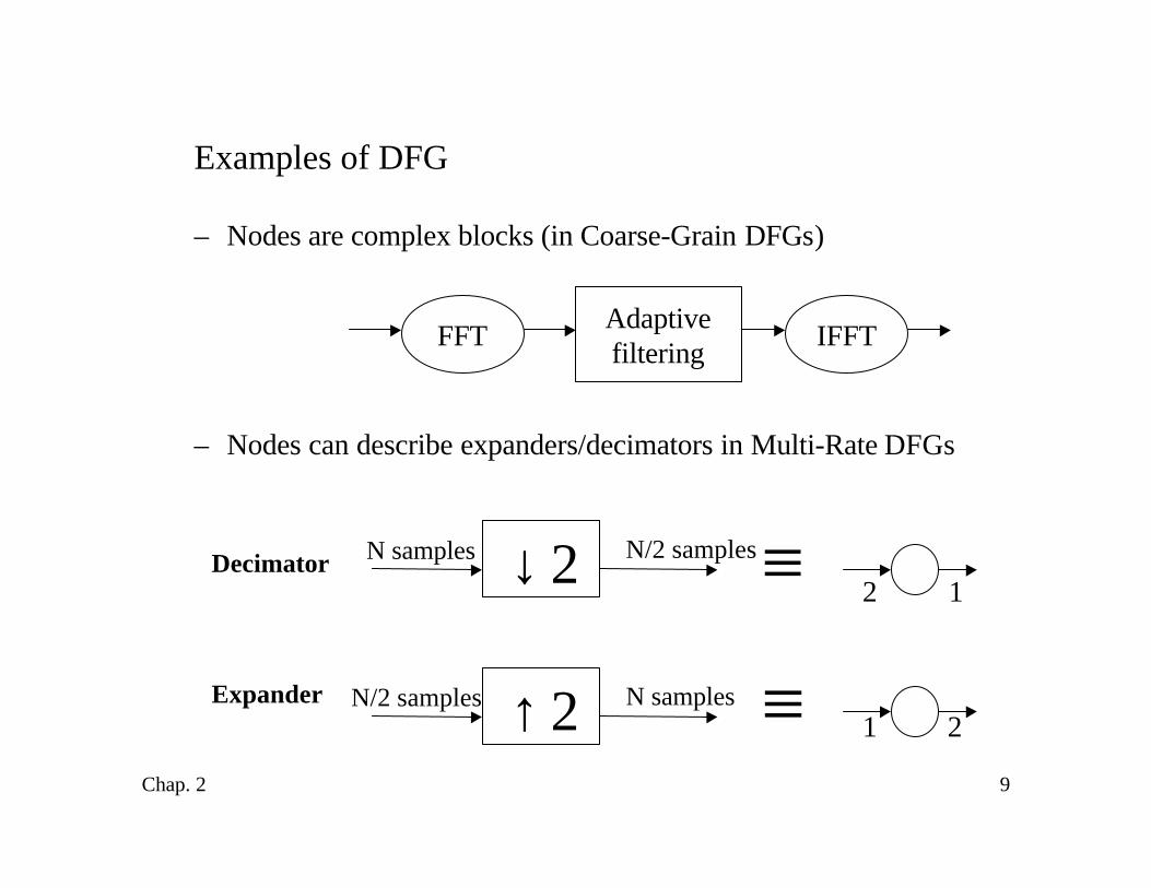
Examples of DFG
– Nodes are complex blocks (in Coarse-Grain DFGs)
– Nodes can describe expanders/decimators in Multi-Rate DFGs
FFT IFFTAdaptivefiltering
2↓N samples N/2 samples
2↑N/2 samples N samples ≡
≡ 2 1
1 2
Decimator
Expander
10Chap. 2
Chapter 2: Iteration Bound
• Introduction• Loop Bound
– Important Definitions and Examples
• Iteration Bound– Important Definitions and Examples– Techniques to Compute Iteration Bound
11Chap. 2
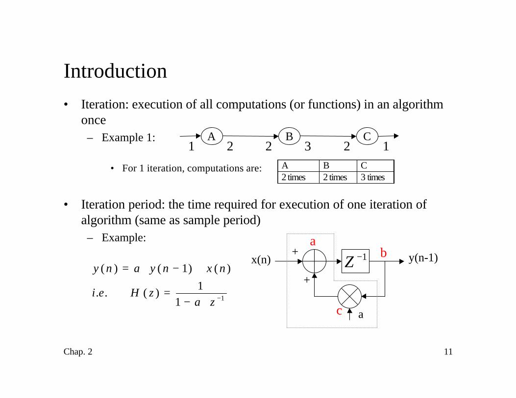
Introduction• Iteration: execution of all computations (or functions) in an algorithm
once– Example 1:
• For 1 iteration, computations are:
• Iteration period: the time required for execution of one iteration ofalgorithm (same as sample period)– Example:
A1 2
B C2 3 2 1
A B C 2 times 2 times 3 times
1−Z y(n-1)x(n)
a
+
+11
1)(..
)()1()(
−⋅−=
+−⋅=
zazHei
nxnyany
c
ba
12Chap. 2
Introduction (cont’d)
– Assume the execution times of multiplier and adder are Tm & Ta, then theiteration period for this example is Tm+ Ta (assume 10ns, see the red-colorbox). so for the signal, the sample period (Ts) must satisfy:
• Definitions:– Iteration rate: the number of iterations executed per second– Sample rate: the number of samples processed in the DSP system per
second (also called throughput)
ams TTT +≥

13Chap. 2
Iteration Bound
• Definitions:– Loop: a directed path that begins and ends at the same node– Loop bound of the j-th loop: defined as Tj/Wj, where Tj is the loop
computation time & Wj is the number of delays in the loop– Example 1: a→ b→ c→ a is a loop (see the same example in Note 2,
PP2), its loop bound:
– Example 2: y(n) = a*y(n-2) + x(n), we have:
2D y(n-2)x(n)
a
+
+ nsTT
T amloopbound 5
2=
+=
nsTTT amloopbound 10=+=

14Chap. 2
Iteration Bound (cont’d)– Example 3: compute the loop_bounds of the following loops:
• Definitions (Important):– Critical Loop: the loop with the maximum loop bound– Iteration bound of a DSP program: the loop bound of the critical loop, it is
defined as
– Example 4: compute the iteration bound of the example 3:
nsT
nsTnsT
L
L
L
5.72)3210(
52)532(121)210(
3
2
1
=++==++=
=+=
10ns A DB C2ns 3ns 5ns
L1: D
L3: 2D
L2: 2D
=∈∞
j
j
Lj W
TT max
where L is the set of loops in the DSP system,Tj is the computation time of the loop j andWj is the number of delays in the loop j
{ }5.7,5,12maxLl
T∈
∞ =

15Chap. 2
Iteration bound (cont’d)
• If no delay element in the loop, then– Delay-free loops are non-computable, see the example:
• Non-causal systems cannot be implemented
• Speed of the DSP system: depends on the “critical path comp. time”– Paths: do not contain delay elements (4 possible path locations)
• (1) input node →delay element• (2) delay element’s output → output node• (3) input node → output node• (4) delay element → delay element
– Critical path of a DFG: the path with the longest computation time amongall paths that contain zero delays
– Clock period is lower bounded by the critical path computation time
∞==∞ 0LTTA B
A BZ
⋅=−⋅=
− causalZBAcausalnonZAB
1
16Chap. 2
Iteration Bound (cont’d)
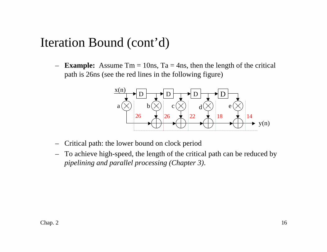
– Example: Assume Tm = 10ns, Ta = 4ns, then the length of the criticalpath is 26ns (see the red lines in the following figure)
– Critical path: the lower bound on clock period– To achieve high-speed, the length of the critical path can be reduced by
pipelining and parallel processing (Chapter 3).
D D D D
a b c d e
x(n)
y(n)26 26 22 18 14
17Chap. 2
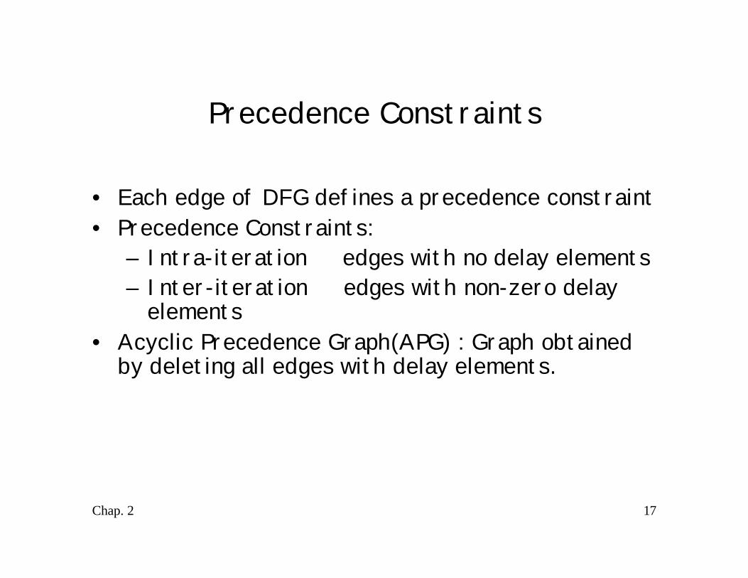
Precedence Constraints
• Each edge of DFG defines a precedence constraint• Precedence Constraints:
– Intra-iteration ⇒ edges with no delay elements– Inter-iteration ⇒ edges with non-zero delay
elements• Acyclic Precedence Graph(APG) : Graph obtained
by deleting all edges with delay elements.
18Chap. 2
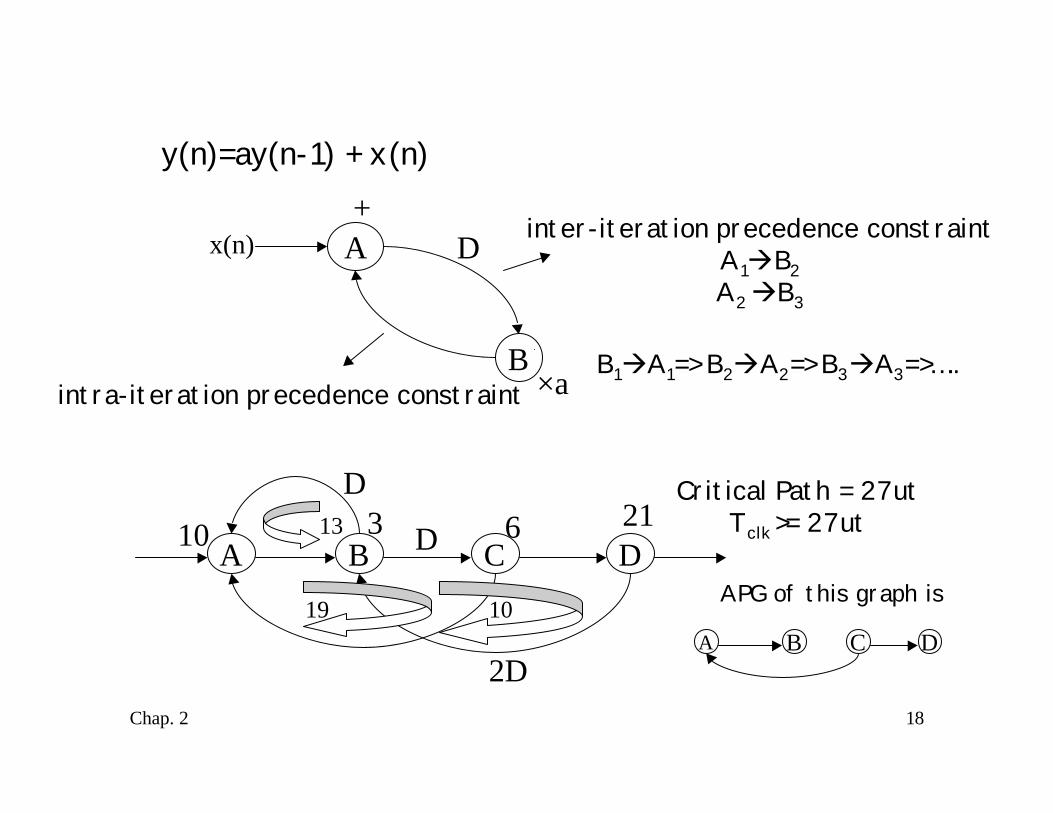
y(n)=ay(n-1) + x(n)
A
B
inter-iteration precedence constraintA1àB2A2 àB3
D+
×aintra-iteration precedence constraintB1àA1=> B2àA2=> B3àA3=>…..
A B C D
D
D
2D
10 3 6 2113
19 10
Critical Path = 27utTclk >= 27ut
A B C D
APG of this graph is
x(n)
19Chap. 2
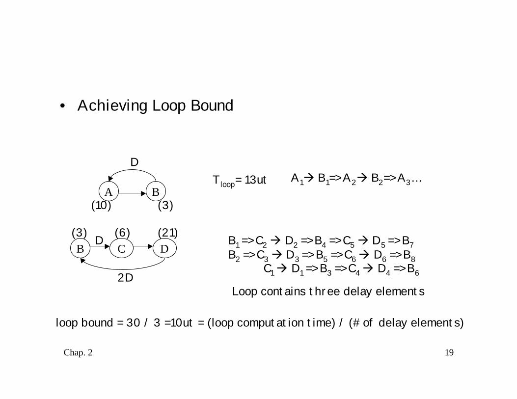
• Achieving Loop Bound
A B
D
(10) (3)
Tloop= 13ut A1à B1=> A2à B2=> A3….
B C D(3) (6) (21)D
2D
B1 => C2 à D2 => B4 => C5 à D5 => B7B2 => C3 à D3 => B5 => C6 à D6 => B8 C1 à D1 => B3 => C4 à D4 => B6
Loop contains three delay elements
loop bound = 30 / 3 =10ut = (loop computation time) / (#of delay elements)
20Chap. 2
• Algorithms to compute iteration bound– Longest Path Matrix (LPM)– Minimum Cycle Mean (MCM)
21Chap. 2
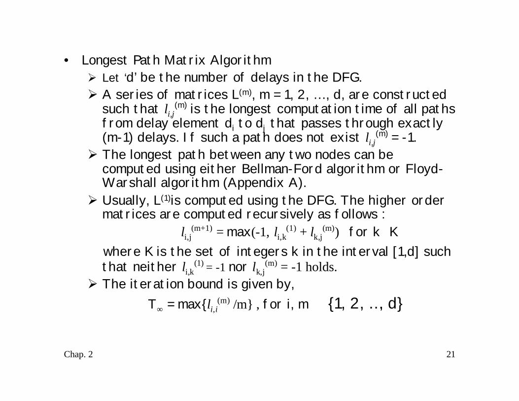
• Longest Path Matrix AlgorithmØ Let ‘d’ be the number of delays in the DFG.Ø A series of matrices L(m), m = 1, 2, … , d, are constructed
such that li,j(m) is the longest computation time of all pathsfrom delay element di to dj that passes through exactly(m-1) delays. If such a path does not exist li,j(m) = -1.
Ø The longest path between any two nodes can becomputed using either Bellman-Ford algorithm or Floyd-Warshall algorithm (Appendix A).
Ø Usually, L(1)is computed using the DFG. The higher ordermatrices are computed recursively as follows :
li,j(m+1) = max(-1, li,k(1) + lk,j
(m)) for k∈K where K is the set of integers k in the interval [1,d] such
that neither li,k(1) = -1 nor lk,j(m) = -1 holds.
Ø The iteration bound is given by, T∞ = max{li,i(m) /m} , for i, m ∈ {1, 2, …, d}
22Chap. 2
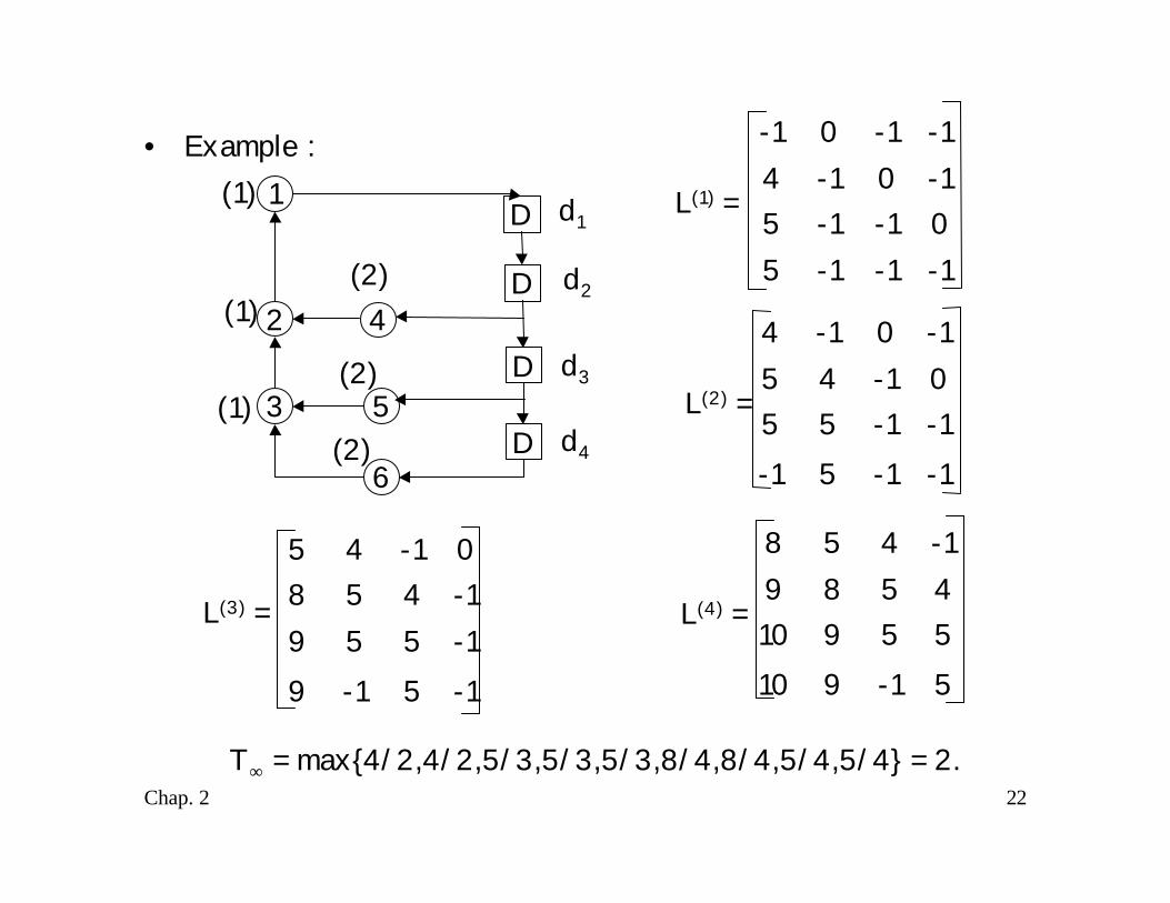
• Example :1
2
3
4
5
6
D
D
D
D
(1)
(1)
(1)
(2)
(2)
(2)
d1
d2
d3
d4
-1-1-150-1-15-10-14-1-10-1
L(1) =
-1-15-1-1-1550-145-10-14
L(3) =
-15-19-1559-14580-145
5-1910559104589-1458
L(4) =
L(2) =
T∞ = max{4/2,4/2,5/3,5/3,5/3,8/4,8/4,5/4,5/4} = 2.
23Chap. 2
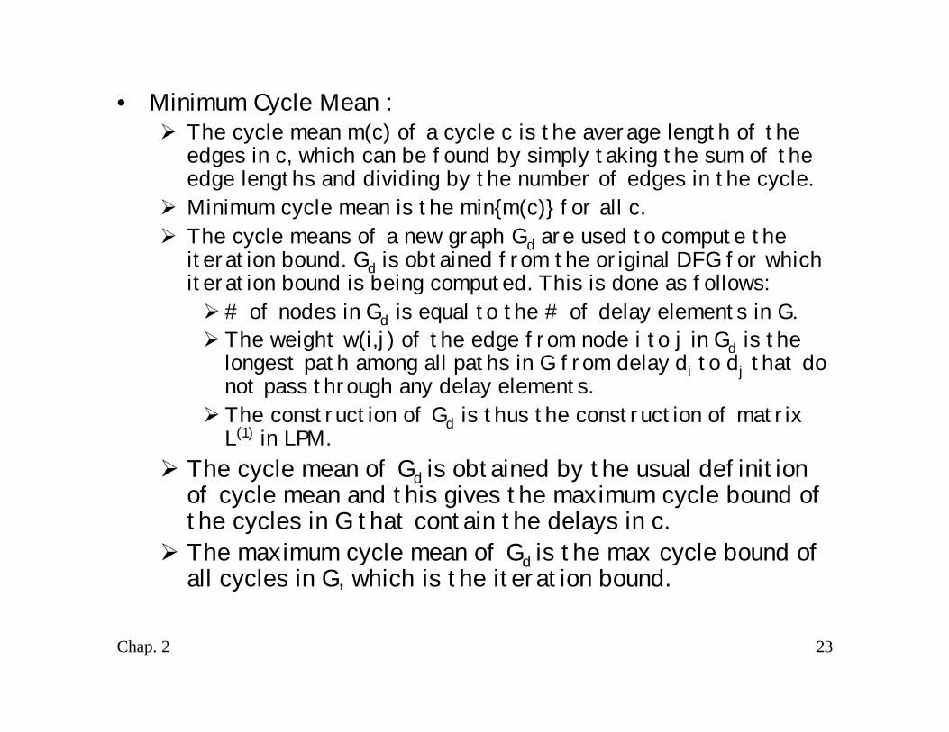
• Minimum Cycle Mean :Ø The cycle mean m(c) of a cycle c is the average length of the
edges in c, which can be found by simply taking the sum of theedge lengths and dividing by the number of edges in the cycle.
Ø Minimum cycle mean is the min{m(c)} for all c.Ø The cycle means of a new graph Gd are used to compute the
iteration bound. Gd is obtained from the original DFG for whichiteration bound is being computed. This is done as follows:Ø# of nodes in Gd is equal to the # of delay elements in G.Ø The weight w(i,j) of the edge from node i to j in Gd is the
longest path among all paths in G from delay di to dj that donot pass through any delay elements.Ø The construction of Gd is thus the construction of matrix
L(1) in LPM.Ø The cycle mean of Gd is obtained by the usual definition
of cycle mean and this gives the maximum cycle bound ofthe cycles in G that contain the delays in c.
Ø The maximum cycle mean of Gd is the max cycle bound ofall cycles in G, which is the iteration bound.
24Chap. 2
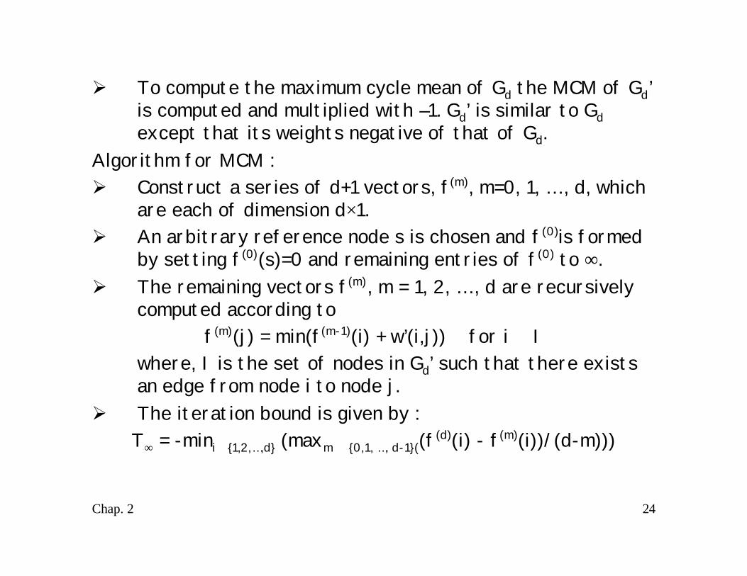
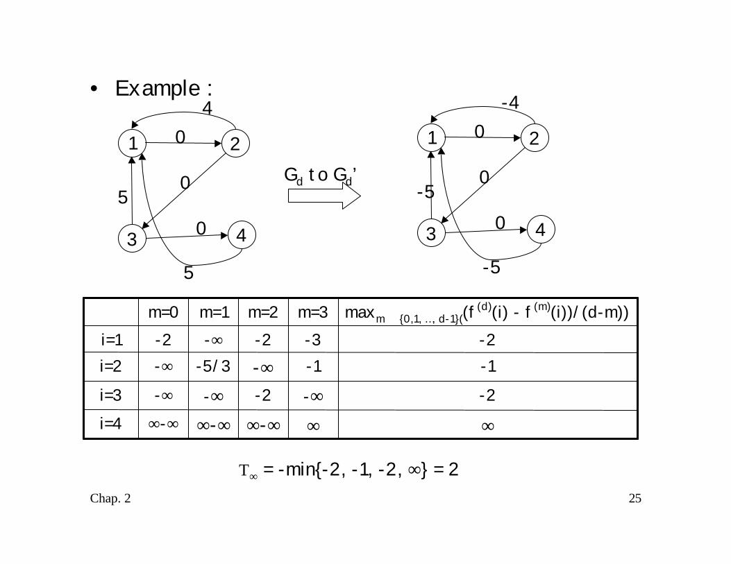
Ø To compute the maximum cycle mean of Gd the MCM of Gd’is computed and multiplied with –1. Gd’ is similar to Gdexcept that its weights negative of that of Gd.
Algorithm for MCM :Ø Construct a series of d+1 vectors, f(m), m=0, 1, … , d, which
are each of dimension d×1.Ø An arbitrary reference node s is chosen and f(0)is formed
by setting f(0)(s)=0 and remaining entries of f(0) to ∞.Ø The remaining vectors f(m), m = 1, 2, … , d are recursively
computed according tof(m)(j) = min(f(m-1)(i) + w’(i,j)) for i ∈ I
where, I is the set of nodes in Gd’ such that there existsan edge from node i to node j.
Ø The iteration bound is given by :T∞ = -mini ∈{1,2,…,d} (maxm ∈ {0,1, …, d-1}((f(d)(i) - f(m)(i))/(d-m)))
25Chap. 2
• Example :
1
43
2
0
0
04
5
5
1
43
2
0
0
0-4
-5
-5
Gd to Gd’
∞∞∞-∞∞-∞∞-∞i=4-2-∞-2-∞-∞i=3
-1-1-∞-5/3-∞i=2-2-3-2-∞-2i=1
maxm ∈ {0,1, …, d-1}((f(d)(i) - f(m)(i))/(d-m))m=3m=2m=1m=0
T∞ = -min{-2, -1, -2, ∞} = 2


![ECE-V-DIGITAL SIGNAL PROCESSING [10EC52] …vtusolution.in/.../digital-signal-processing-10ec52.pdfDigital vtusolution.in Signal Processing 10EC52 TEXT BOOK: 1. DIGITAL SIGNAL PROCESSING](https://img.dokumen.tips/doc/110x75/5afe42bb7f8b9a256b8ccd2e/ece-v-digital-signal-processing-10ec52-signal-processing-10ec52-text-book.jpg)