Embed Size (px)
Citation preview

Virtual Networking Management White Paper
Version 1.0.0 Status: DMTF Informational Publication Date: 2012-02-14
DSP2025
Virtual Networking Management White Paper DSP2025
Page 2 DMTF Informational 1.0.0
Copyright Notice
Copyright © 2012 Distributed Management Task Force, Inc. (DMTF). All rights reserved.
DMTF is a not-for-profit association of industry members dedicated to promoting enterprise and systems management and interoperability. Members and non-members may reproduce DMTF specifications and documents, provided that correct attribution is given. As DMTF specifications may be revised from time to time, the particular version and release date should always be noted.
Implementation of certain elements of this standard or proposed standard may be subject to third party patent rights, including provisional patent rights (herein "patent rights"). DMTF makes no representations to users of the standard as to the existence of such rights, and is not responsible to recognize, disclose, or identify any or all such third party patent right, owners or claimants, nor for any incomplete or inaccurate identification or disclosure of such rights, owners or claimants. DMTF shall have no liability to any party, in any manner or circumstance, under any legal theory whatsoever, for failure to recognize, disclose, or identify any such third party patent rights, or for such party’s reliance on the standard or incorporation thereof in its product, protocols or testing procedures. DMTF shall have no liability to any party implementing such standard, whether such implementation is foreseeable or not, nor to any patent owner or claimant, and shall have no liability or responsibility for costs or losses incurred if a standard is withdrawn or modified after publication, and shall be indemnified and held harmless by any party implementing the standard from any and all claims of infringement by a patent owner for such implementations.
For information about patents held by third-parties which have notified the DMTF that, in their opinion, such patent may relate to or impact implementations of DMTF standards, visit http://www.dmtf.org/about/policies/disclosures.php.
DSP2025 Virtual Networking Management White Paper
1.0.0 DMTF Informational Page 3
Virtual Networking Management White Paper Version 1.0.0c
Publication Date: 2011-12-24 DSP2025
Status: DMTF Draft White Paper
Abstract
Virtual networking enables virtual computer systems (a.k.a. virtual machines) to be networked together. This white paper describes virtual networking management standards developed by the DMTF. Specifically, this white paper provides an overview of the following:
1. Extensions to the DMTF Common Information Model (CIM) for the Ethernet port resource virtualization and management of virtual networking components including virtual Ethernet ports, virtual Ethernet switches, and Edge Virtual Bridging (EVB) as defined by IEEE 802.1Qbg.
2. Network Port Profile XML Schema to represent networking attributes of a virtual computer system or a set of virtual computer systems.
3. Extensions to Open Virtualization Format (OVF) for the incorporation of Network Port Profiles.
Virtual Networking Management White Paper DSP2025
Page 4 DMTF Informational 1.0.0
Acknowledgments
The authors acknowledge the contributions from the members of the DMTF System Virtualization, Partitioning, and Cluster (SVPC) Virtual Networking Sub Group. The following persons were instrumental in the development of this specification:
• (Editor) Hemal Shah, Broadcom Corporation
• (Editor) Murali Rajagopal, QLogic
• (Editor) Shishir Pardikar, Citrix
• John Crandall, Brocade Communications Systems
• Pat Thaler, Broadcom Corporation
• Uri Elzur, Broadcom Corporation
• Mike Krause, HP
• Jeff Wheeler, Huawei
• Kevin Fox, Huawei
• Michael Johanssen, IBM
• Ilango Ganga, Intel Corporation
• John Parchem, Microsoft Corporation
• Shravan Gaonkar, NetApp
• Larry Lamers, VMware
• Fred Maciel, Hitachi
DSP2025 Virtual Networking Management White Paper
1.0.0 DMTF Informational Page 5
Table of Contents Abstract ................................................................................................................................................. 3 Acknowledgments ................................................................................................................................. 4 Table of Contents .................................................................................................................................. 5 List of Figures ........................................................................................................................................ 6 List of Tables ......................................................................................................................................... 6
1 Introduction ............................................................................................................................................ 7 1.1 Targeted Audience ...................................................................................................................... 7 1.2 Related Documents .................................................................................................................... 7 1.3 Terminology ................................................................................................................................ 8
1.3.1 Edge Virtual Bridging (EVB) .......................................................................................... 8 1.3.2 Embedded Switch (eSwitch) .......................................................................................... 8 1.3.3 Network Interface Controller (NIC) ................................................................................ 8 1.3.4 Network Port Profile ....................................................................................................... 8 1.3.5 Network Port Profile Database (NPPDB) ...................................................................... 8 1.3.6 Physical NIC (pNIC) ....................................................................................................... 8 1.3.7 Virtual Ethernet Bridge (VEB) ........................................................................................ 9 1.3.8 Virtual Ethernet Port Aggregator (VEPA) ...................................................................... 9 1.3.9 Virtual Ethernet Switch .................................................................................................. 9 1.3.10 Virtual Machine (VM) ..................................................................................................... 9 1.3.11 Virtual Network Interface Controller (vNIC) ................................................................... 9 1.3.12 Virtual Station Interface (VSI) ........................................................................................ 9 1.3.13 Virtual Switch (vSwitch) ................................................................................................. 9
1.4 Overview ..................................................................................................................................... 9 1.4.1 Management Challenges and Virtual Networking Management (VNM) ........................ 9 1.4.2 Virtual Networking Management (VNM) Model Components ...................................... 11 1.4.3 DMTF SVPC Virtual Networking Concepts ................................................................. 13
1.5 Goals and Scope ...................................................................................................................... 19 1.6 Relationships to Other DMTF Standards and Specifications ................................................... 21
2 Virtual Networking Concepts ............................................................................................................... 23 2.1 Virtual Station Interface (VSI) ................................................................................................... 23 2.2 Virtual Ethernet Bridge (VEB) ................................................................................................... 23 2.3 Virtual Ethernet Port Aggregation (VEPA) ................................................................................ 26
3 CIM Classes for Virtual Networking Components ............................................................................... 30 3.1 Ethernet Port ............................................................................................................................. 30 3.2 Ethernet Port Resource Virtualization ....................................................................................... 32 3.3 Basic Virtual Network Model ..................................................................................................... 34 3.4 Virtual Ethernet Switch.............................................................................................................. 35
4 Management Use Cases for Virtual Networking ................................................................................. 37 4.1 Virtual NIC Management .......................................................................................................... 37
4.1.1 Use Cases Covered By Ethernet Port Profile .............................................................. 37 4.1.2 Use Cases Covered By Ethernet Port Resource Virtualization Profile ........................ 37 4.1.3 Use Cases for EVB Settings Management .................................................................. 37
4.2 Virtual Ethernet Switch Management ....................................................................................... 38 4.2.1 Use Cases for EVB Management ................................................................................ 38
4.3 Lifecycle Operations for Example Use Cases .......................................................................... 39 4.3.1 Use Cases ................................................................................................................... 39 4.3.2 Use Case 1 .................................................................................................................. 39 4.3.3 Use Case 2 .................................................................................................................. 39 4.3.4 Life Cycle Operations for Use Case 1a ....................................................................... 45 4.3.5 Life Cycle Operations for Use Case 1b ....................................................................... 46
5 Network Port Profile XML Schema ...................................................................................................... 47 5.1 Network Port-Profile XML Schema ........................................................................................... 47 5.2 Network Port Profile Representation in OVF ............................................................................ 47 5.3 Network Port Profile Use Cases ............................................................................................... 48

Virtual Networking Management White Paper DSP2025
Page 6 DMTF Informational 1.0.0
5.3.1 Network Port Profile Use Case 1 ................................................................................. 48 5.3.2 Network Port Profile Use Case 2 ................................................................................. 49 5.3.3 Network Port Profile Use Case 3 ................................................................................. 50
ANNEX A (Informative) VLAN Concepts ............................................................................................. 52 ANNEX B (Informative) Network Port Profile Example XML Documents ........................................... 53 ANNEX C (informative) Change log ................................................................................................... 57
List of Figures Figure 1 – Virtual Networking Management (VNM) Model ......................................................................... 11 Figure 2 – Virtual Networking Server and Attached Bridge Components ................................................... 12 Figure 3 – One Software Switch with a Matching Hardware Switch ........................................................... 13 Figure 4 – Multiple Software Switches ........................................................................................................ 14 Figure 5 – Multiple Software Switches and Multiple Hardware Switches in one EVB Mode ...................... 14 Figure 6 – Multiple Matching Software and Hardware switches ................................................................. 15 Figure 7 – Basic System Virtualization Model ............................................................................................. 16 Figure 8 – Virtual System with Device and State Extension ....................................................................... 17 Figure 9 – Resource Pools and Resource Allocation ................................................................................. 18 Figure 10 – Scope of SVPC Virtual Networking Working Group ................................................................ 20 Figure 11 – CIM Profiles Related to Virtual Networking ............................................................................. 22 Figure 12 – Example Hypervisor with Multiple VM, Multiple NIC, attached to an Attached Bridge ............ 23 Figure 13 – Example Physical End Station with Multiple VMs and two Software VEBs ............................ 24 Figure 14 – Example Physical End Station with Multiple Hardware VEBs ................................................. 25 Figure 15 – VEB Frame Relay Support ...................................................................................................... 25 Figure 16 – Example Physical End Station with Multiple VM Communicating through a VEPA ................ 27 Figure 17 – VEPA Frame Relay Support .................................................................................................... 28 Figure 18 – CIM_EthernetPort Class Hierarchy.......................................................................................... 31 Figure 19 – CIM_LANEndPoint and CIM_VLANEndPoint Classes ............................................................ 32 Figure 20 – CIM_VLANEndpointSettingData and CIM_NetworkVLAN Classes ........................................ 32 Figure 21 – CIM_EthernetPortAllocationSettingData Class ....................................................................... 33 Figure 22 – Basic CIM Network Model ....................................................................................................... 35 Figure 23 – Example CIM Model for Virtual Ethernet Switch ...................................................................... 36 Figure 24 – Use Case 1 Data and Control Model ....................................................................................... 40 Figure 25 – Use Case 2 Data Model ........................................................................................................... 41 Figure 26 – Conceptual Model for Use Case 1 ........................................................................................... 42 Figure 27 – CIM Connectivity Model for Use Case 1 .................................................................................. 43 Figure 28 – Conceptual Model for Use Case 2 ........................................................................................... 44 Figure 29 – CIM Connectivity Model for Use Case 2 .................................................................................. 45 Figure 30 – Network Port Profile Representation inside an OVF Package ................................................ 48 Figure 31 – Network Port Profile Use Case 1 ............................................................................................. 49 Figure 32 – Network Port Profile Use Case 2 ............................................................................................. 50 Figure 33 – Network Port Profile Use Case 3 ............................................................................................. 51
List of Tables Table 1 – Example Lifecycle Operations for Use Case 1a ......................................................................... 45 Table 2 – Lifecycle Operations for Use Case 1b ........................................................................................ 46
DSP2025 Virtual Networking Management White Paper
1.0.0 DMTF Informational Page 7
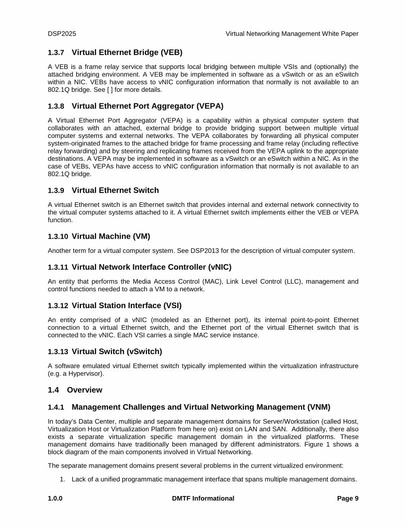
1 Introduction Virtual networking enables connectivity between the virtual computer systems that are networked together. Virtual computer systems connect to each other and to the network using virtual Ethernet ports and virtual Ethernet switches. The complexity and cost of managing virtual networking components can be reduced by developing standards for virtual networking management.
DMTF has developed a set of standards for the management of virtual networking components. These standards complement the DMTF standards developed for the management of physical and virtual computer systems. This white paper describes the following virtual networking management standards.
1. Extensions to the DMTF Common Information Model (CIM) for virtual networking: The CIM extensions for virtual networking components cover the Ethernet port resource virtualization and management of virtual networking components including virtual Ethernet ports, virtual Ethernet switches, and Edge Virtual Bridging (EVB) as defined by IEEE 802.1Qbg. These extensions provide a standard based management interface for the runtime and dynamic management of virtual networking components.
2. Network Port Profile XML Schema: is an XML schema that can be used to represent networking attributes of a virtual computer system or a set of virtual computer systems. This schema enables a standard format for the representation of networking attributes that can be used during the provisioning and deployment of the virtual computer systems.
3. Extensions to Open Virtualization Format (OVF) for the incorporation of Network Port Profiles: The incorporation of network port profiles in the OVF allows the packaging and distribution of networking attributes for a set of virtual computer systems using a common packaging format.
1.1 Targeted Audience
The intended target audience for this paper is readers who want to understand the CIM based information models for the management of virtual networking components and the networking attributes representation in OVF. Familiarity with virtualization and CIM is assumed from the readers of this white paper.
1.2 Related Documents [1] DMTF DSP0243, Open Virtualization Format 1.1
[2] DMTF DSP0243, Open Virtualization Format 2.0
[3] DMTF DSP1014, Ethernet Port Profile 1.0
[4] DMTF DSP1041, Resource Allocation Profile 1.1
[5] DMTF DSP1042, System Virtualization Profile 1.0
[6] DMTF DSP1043, Allocation Capabilities Profile 1.0
[7] DMTF DSP1050, Ethernet Port Resource Virtualization Profile 1.1
[8] DMTF DSP1052, Computer System Profile 1.0
[9] DMTF DSP1057, Virtual System Profile 1.0
[10] DMTF DSP1059, Generic Device Resource Virtualization Profile 1.0
[11] DMTF DSP1097, Virtual Ethernet Switch Profile 1.1
[12] DMTF DSP2013, Virtualization Management White Paper 1.0
Virtual Networking Management White Paper DSP2025
Page 8 DMTF Informational 1.0.0
[13] DMTF DSP2017, Open Virtualization Format White Paper 1.0
[14] DMTF DSP8023, OVF Envelope XSD, 1.1
[15] DMTF DSP8023, OVF Envelope XSD, 2.0
[16] DMTF DSP8027, OVF Environment XSD, 1.1
[17] IEEE Std 802.1QazTM-2011, Standard for Local and metropolitan area networks – Media Access Control (MAC) Bridges and Virtual Bridged Local Area Networks – Amendment 18: Enhanced Transmission Selection for Bandwidth Sharing between Traffic Classes
[18] IEEE Std 802.1QbbTM-2011, Standard for Local and metropolitan area networks – Media Access Control (MAC) Bridges and Virtual Bridged Local Area Networks – Amendment 17: Priority-based Flow Control
[19] IEEE P802.1QbgTM-20xx, Standard for Local and metropolitan area networks – Media Access Control (MAC) Bridges and Virtual Bridged Local Area Networks – Amendment xx: Edge Virtual Bridging
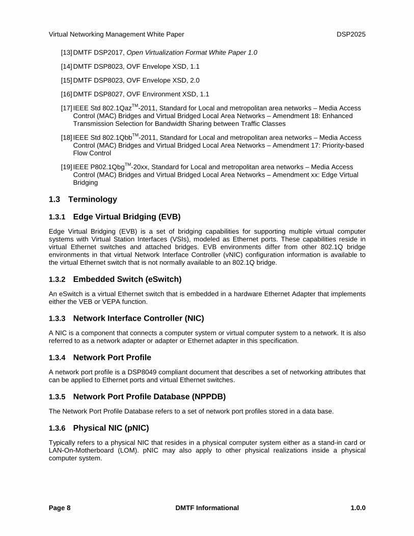
1.3 Terminology
1.3.1 Edge Virtual Bridging (EVB)
Edge Virtual Bridging (EVB) is a set of bridging capabilities for supporting multiple virtual computer systems with Virtual Station Interfaces (VSIs), modeled as Ethernet ports. These capabilities reside in virtual Ethernet switches and attached bridges. EVB environments differ from other 802.1Q bridge environments in that virtual Network Interface Controller (vNIC) configuration information is available to the virtual Ethernet switch that is not normally available to an 802.1Q bridge.
1.3.2 Embedded Switch (eSwitch)
An eSwitch is a virtual Ethernet switch that is embedded in a hardware Ethernet Adapter that implements either the VEB or VEPA function.
1.3.3 Network Interface Controller (NIC)
A NIC is a component that connects a computer system or virtual computer system to a network. It is also referred to as a network adapter or adapter or Ethernet adapter in this specification.
1.3.4 Network Port Profile
A network port profile is a DSP8049 compliant document that describes a set of networking attributes that can be applied to Ethernet ports and virtual Ethernet switches.
1.3.5 Network Port Profile Database (NPPDB)
The Network Port Profile Database refers to a set of network port profiles stored in a data base.
1.3.6 Physical NIC (pNIC)
Typically refers to a physical NIC that resides in a physical computer system either as a stand-in card or LAN-On-Motherboard (LOM). pNIC may also apply to other physical realizations inside a physical computer system.
DSP2025 Virtual Networking Management White Paper
1.0.0 DMTF Informational Page 9
1.3.7 Virtual Ethernet Bridge (VEB)
A VEB is a frame relay service that supports local bridging between multiple VSIs and (optionally) the attached bridging environment. A VEB may be implemented in software as a vSwitch or as an eSwitch within a NIC. VEBs have access to vNIC configuration information that normally is not available to an 802.1Q bridge. See [ ] for more details.
1.3.8 Virtual Ethernet Port Aggregator (VEPA)
A Virtual Ethernet Port Aggregator (VEPA) is a capability within a physical computer system that collaborates with an attached, external bridge to provide bridging support between multiple virtual computer systems and external networks. The VEPA collaborates by forwarding all physical computer system-originated frames to the attached bridge for frame processing and frame relay (including reflective relay forwarding) and by steering and replicating frames received from the VEPA uplink to the appropriate destinations. A VEPA may be implemented in software as a vSwitch or an eSwitch within a NIC. As in the case of VEBs, VEPAs have access to vNIC configuration information that normally is not available to an 802.1Q bridge.
1.3.9 Virtual Ethernet Switch
A virtual Ethernet switch is an Ethernet switch that provides internal and external network connectivity to the virtual computer systems attached to it. A virtual Ethernet switch implements either the VEB or VEPA function.
1.3.10 Virtual Machine (VM)
Another term for a virtual computer system. See DSP2013 for the description of virtual computer system.
1.3.11 Virtual Network Interface Controller (vNIC)
An entity that performs the Media Access Control (MAC), Link Level Control (LLC), management and control functions needed to attach a VM to a network.
1.3.12 Virtual Station Interface (VSI)
An entity comprised of a vNIC (modeled as an Ethernet port), its internal point-to-point Ethernet connection to a virtual Ethernet switch, and the Ethernet port of the virtual Ethernet switch that is connected to the vNIC. Each VSI carries a single MAC service instance.
1.3.13 Virtual Switch (vSwitch)
A software emulated virtual Ethernet switch typically implemented within the virtualization infrastructure (e.g. a Hypervisor).
1.4 Overview
1.4.1 Management Challenges and Virtual Networking Management (VNM)
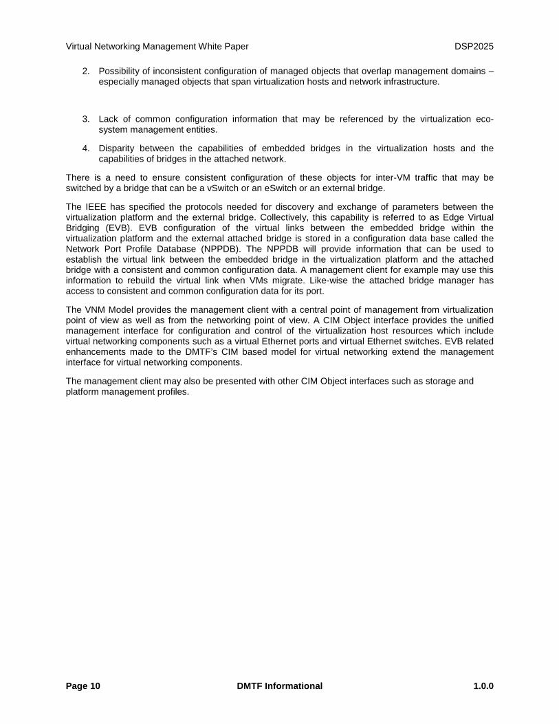
In today’s Data Center, multiple and separate management domains for Server/Workstation (called Host, Virtualization Host or Virtualization Platform from here on) exist on LAN and SAN. Additionally, there also exists a separate virtualization specific management domain in the virtualized platforms. These management domains have traditionally been managed by different administrators. Figure 1 shows a block diagram of the main components involved in Virtual Networking.
The separate management domains present several problems in the current virtualized environment:
1. Lack of a unified programmatic management interface that spans multiple management domains.
Virtual Networking Management White Paper DSP2025
Page 10 DMTF Informational 1.0.0
2. Possibility of inconsistent configuration of managed objects that overlap management domains – especially managed objects that span virtualization hosts and network infrastructure.
3. Lack of common configuration information that may be referenced by the virtualization eco-system management entities.
4. Disparity between the capabilities of embedded bridges in the virtualization hosts and the capabilities of bridges in the attached network.
There is a need to ensure consistent configuration of these objects for inter-VM traffic that may be switched by a bridge that can be a vSwitch or an eSwitch or an external bridge.
The IEEE has specified the protocols needed for discovery and exchange of parameters between the virtualization platform and the external bridge. Collectively, this capability is referred to as Edge Virtual Bridging (EVB). EVB configuration of the virtual links between the embedded bridge within the virtualization platform and the external attached bridge is stored in a configuration data base called the Network Port Profile Database (NPPDB). The NPPDB will provide information that can be used to establish the virtual link between the embedded bridge in the virtualization platform and the attached bridge with a consistent and common configuration data. A management client for example may use this information to rebuild the virtual link when VMs migrate. Like-wise the attached bridge manager has access to consistent and common configuration data for its port.
The VNM Model provides the management client with a central point of management from virtualization point of view as well as from the networking point of view. A CIM Object interface provides the unified management interface for configuration and control of the virtualization host resources which include virtual networking components such as a virtual Ethernet ports and virtual Ethernet switches. EVB related enhancements made to the DMTF’s CIM based model for virtual networking extend the management interface for virtual networking components.
The management client may also be presented with other CIM Object interfaces such as storage and platform management profiles.
DSP2025 Virtual Networking Management White Paper
1.0.0 DMTF Informational Page 11
Virtualization Platform Network Infrastructure
AdjacentBridge
Eth Port
VMEdge
Virtualization Platform Edge
Bridge Edge
Virtual Computer
System
Virtual Computer
System
Eth Port
Eth Port
PhysicalNIC
Eth Port
Virtualization Layer
Virtual Ethernet Switch
Eth Port
Eth Port
Eth Port
Management ClientNetwork Port Profile Database
(NPPDB)
LAN
Figure 1 – Virtual Networking Management (VNM) Model
1.4.2 Virtual Networking Management (VNM) Model Components
As noted above, Figure 1 shows the main components involved in Virtual Networking:
1. Virtualization Platform (virtual computer systems, virtualization layer, and physical NICs)
2. Attached Bridge
3. Management Client
4. Network Port Profile Database (NPPDB)
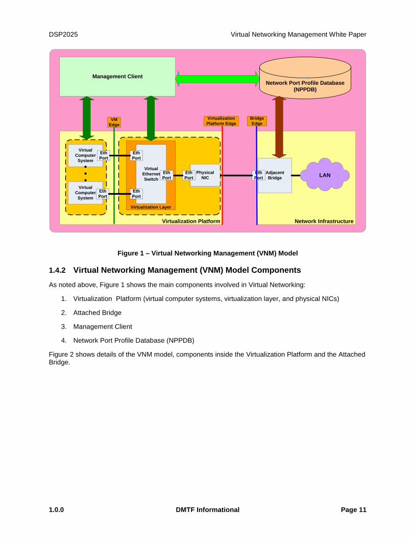
Figure 2 shows details of the VNM model, components inside the Virtualization Platform and the Attached Bridge.
Virtual Networking Management White Paper DSP2025
Page 12 DMTF Informational 1.0.0
pNICS-VLAN Component
S-VLAN ComponentA B C E FDD
A B C E FDD
HW VEB HW VEPA
SW VEB SW VEPA
VM VM VM VM VM VMPhysical
End Station(Host)
Virtual Computer Systems
Direct AccessPhysical
End StationS-Component
Adjacent Bridge
S-Component
S-Channel
Virtual Ethernet
Ports
Figure 2 – Virtual Networking Server and Attached Bridge Components
The following sections provide an overview of the VNM Model Components.
1.4.2.1 Virtualization Platform
The virtualization platform is the infrastructure provided by a host system (or physical end station) to enable the deployment of virtual systems or virtual machines. The virtualization platform includes virtualization management service.
1.4.2.2 Attached Bridge
The attached bridge is an IEEE 802.1Q compliant bridge that is connected to the physical end station through one or more physical Ethernet ports. The key difference between an attached bridge and a generic 802.1D compliant bridge is the support for IEEE defined EVB discovery and control protocols. An attached bridge may support reflective relay capability.
1.4.2.3 Management Client
The management client is the entity that is responsible for the management of the virtualization platform as well as the deployment of virtual machines (VMs) on the virtualization platform.
DSP2025 Virtual Networking Management White Paper
1.0.0 DMTF Informational Page 13
1.4.2.4 Network Port Profile Database (NPPDB)
The Network Port Profile Database (NPPDB) is a repository of one or more sets of network attributes that can be applied to one or more VSIs during the initial deployment of VMs or VM migrations.
1.4.3 DMTF SVPC Virtual Networking Concepts
This section describes virtual Ethernet switch models considered by DMTF and the basic SVPC modeling concepts.
1.4.3.1 Virtual Ethernet Switch Models and Topologies
A virtual Ethernet switch inside a virtualization platform can be either software or hardware based. The virtual Ethernet switch can be operating in VEB or VEPA mode. A set of virtual Ethernet switches can be cascaded inside a virtualization platform. The switches that are cascaded together always operate in the same mode. Below are some examples of the virtual Ethernet switch models that illustrate various topologies that can be found inside a virtualization platform.
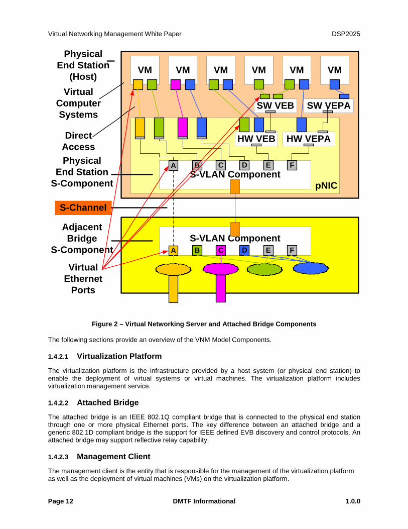
1.4.3.1.1 One Software Switch with a Matching Hardware Switch
The model in Figure 3 shows a software virtual Ethernet switch (vSwitch) and a hardware virtual Ethernet switch (eSwitch) inside a virtualization platform. Both software and hardware switches operate in the same mode (VEB or VEPA). The hardware switch is connected to and possibly controlled by the software switch and will carry consistent settings (e.g., VLAN ID).
Hardware Virtual Ethernet Switch(VEB or VEPA)
VM VM VM
Software Virtual Ethernet Switch (VEB or VEPA)
Figure 3 – One Software Switch with a Matching Hardware Switch
1.4.3.1.2 Multiple Software Switches
The model in Figure 4 below shows multiple software switches inside a virtualization platform. Each software switch operates independently in VEB or VEPA mode. A VM may be connected to multiple software switches.

Virtual Networking Management White Paper DSP2025
Page 14 DMTF Informational 1.0.0
VM VM VM
Software Virtual Ethernet Switch (VEB or VEPA)
Software Virtual Ethernet Switch (VEB or VEPA)
Figure 4 – Multiple Software Switches
1.4.3.1.3 Multiple Software Switches, Multiple Hardware Switches
The model in Figure 5 below shows multiple software switches connected to and possibly controlling multiple hardware switches inside a virtualization platform. The software switches and hardware switches are operating in the same mode (VEB in this example). The first hardware switch is inside physical NIC 1 and the second hardware switch is inside physical NIC 2.
Hardware Virtual Ethernet Switch (VEB)
Physical NIC 1
VM VM VM
Software Virtual Ethernet Switch 2 (VEB)
Hardware Virtual Ethernet Switch (VEB)
Physical NIC 2
VM
Software Virtual Ethernet Switch 1 (VEB)
Figure 5 – Multiple Software Switches and Multiple Hardware Switches in one EVB Mode
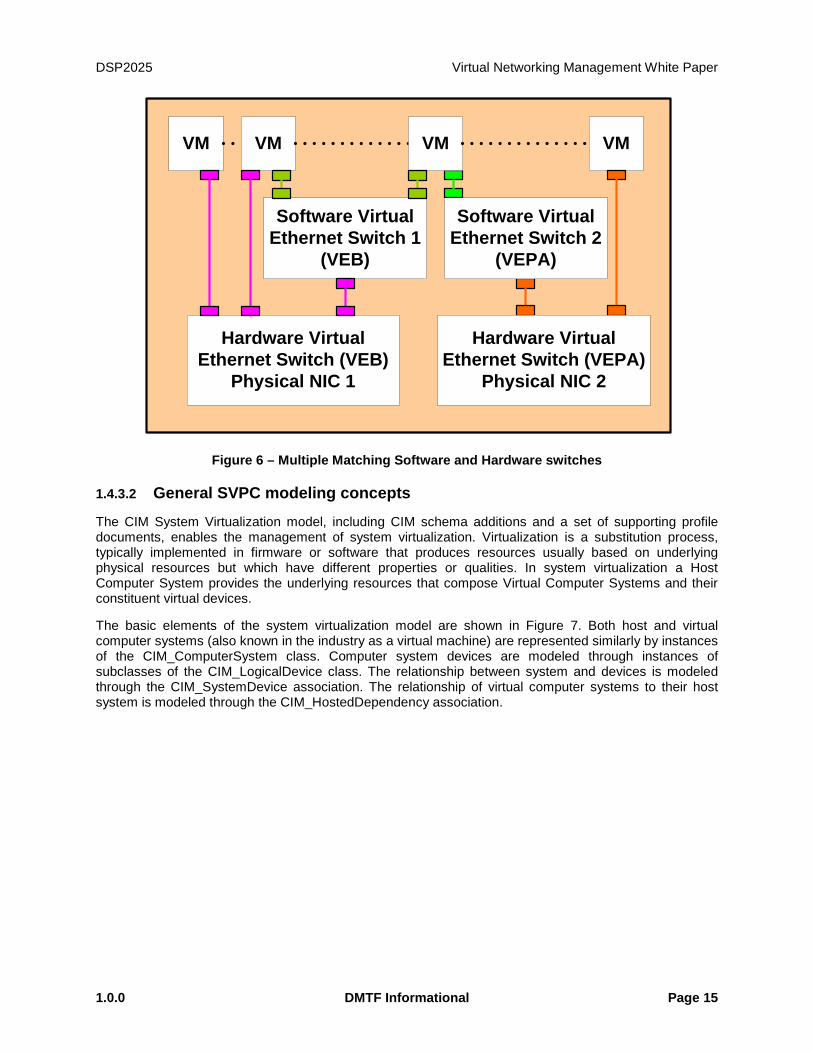
1.4.3.1.4 Multiple Matching Software and Hardware Switches
The model in Figure 6 below shows multiple software and hardware switches inside a virtualization platform. Each software switch and the matching hardware switch operate in the same mode (VEB or VEPA). The hardware switches are connected to and possibly controlled by the software switches. A VM may be connected to a hardware switch or a software switch or both. A VM may also be connected to two different switches in two different modes.
DSP2025 Virtual Networking Management White Paper
1.0.0 DMTF Informational Page 15
Hardware Virtual Ethernet Switch (VEB)
Physical NIC 1
VM VM VM
Software Virtual Ethernet Switch 1
(VEB)
Hardware Virtual Ethernet Switch (VEPA)
Physical NIC 2
VM
Software Virtual Ethernet Switch 2
(VEPA)
Figure 6 – Multiple Matching Software and Hardware switches
1.4.3.2 General SVPC modeling concepts
The CIM System Virtualization model, including CIM schema additions and a set of supporting profile documents, enables the management of system virtualization. Virtualization is a substitution process, typically implemented in firmware or software that produces resources usually based on underlying physical resources but which have different properties or qualities. In system virtualization a Host Computer System provides the underlying resources that compose Virtual Computer Systems and their constituent virtual devices.
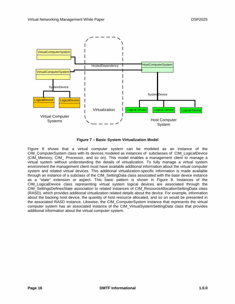
The basic elements of the system virtualization model are shown in Figure 7. Both host and virtual computer systems (also known in the industry as a virtual machine) are represented similarly by instances of the CIM_ComputerSystem class. Computer system devices are modeled through instances of subclasses of the CIM_LogicalDevice class. The relationship between system and devices is modeled through the CIM_SystemDevice association. The relationship of virtual computer systems to their host system is modeled through the CIM_HostedDependency association.
Virtual Networking Management White Paper DSP2025
Page 16 DMTF Informational 1.0.0
HostComputerSystem
VirtualComputerSystem
Host Computer System
Virtual Computer Systems
VirtualComputerSystem
LogicalDevice
SystemDevice
System Device
SystemDevice
Logical Device Logical Device Logical Device
HostedDependency
LogicalDevice
HostedDependency
Virtualization
Figure 7 – Basic System Virtualization Model
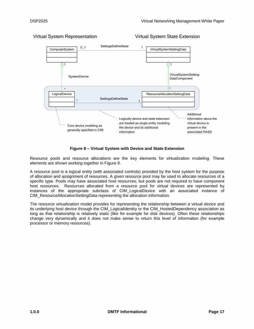
Figure 8 shows that a virtual computer system can be modeled as an instance of the CIM_ComputerSystem class with its devices modeled as instances of subclasses of CIM_LogicalDevice (CIM_Memory, CIM_ Processor, and so on). This model enables a management client to manage a virtual system without understanding the details of virtualization. To fully manage a virtual system environment the management client must have available additional information about the virtual computer system and related virtual devices. This additional virtualization-specific information is made available through an instance of a subclass of the CIM_SettingData class associated with the base device instance as a “state” extension or aspect. This basic pattern is shown in Figure 8. Instances of the CIM_LogicalDevice class representing virtual system logical devices are associated through the CIM_SettingsDefinesState association to related instances of CIM_ResourceAllocationSettingData class (RASD), which provides additional virtualization related details about the device. For example, information about the backing host device, the quantity of host resource allocated, and so on would be presented in the associated RASD instance. Likewise, the CIM_ComputerSystem instance that represents the virtual computer system has an associated instance of the CIM_VirtualSystemSettingData class that provides additional information about the virtual computer system.
DSP2025 Virtual Networking Management White Paper
1.0.0 DMTF Informational Page 17
ComputerSystem VirtualSystemSettingData
LogicalDevice ResourceAllocationSettingData
1
*
SystemDevice
1
*
VirtualSystemSetting-DataComponent
Virtual System State ExtensionVirtual System Representation
0..1 1SettingsDefineState
* 1SettingsDefineState
Additional information about the virtual device is present in the associated RASD
Core device modeling as generally specified in CIM
Logically device and state extension are treated as single entity modeling the device and its additional information
Figure 8 – Virtual System with Device and State Extension
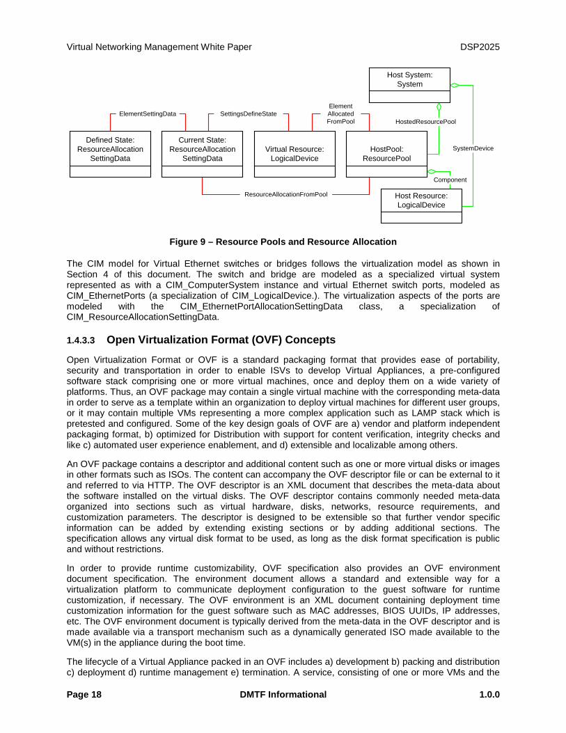
Resource pools and resource allocations are the key elements for virtualization modeling. These elements are shown working together in Figure 9.
A resource pool is a logical entity (with associated controls) provided by the host system for the purpose of allocation and assignment of resources. A given resource pool may be used to allocate resources of a specific type. Pools may have associated host resources, but pools are not required to have component host resources. Resources allocated from a resource pool for virtual devices are represented by instances of the appropriate subclass of CIM_LogicalDevice with an associated instance of CIM_ResourceAllocationSettingData representing the allocation information.
The resource virtualization model provides for representing the relationship between a virtual device and its underlying host device through the CIM_LogicalIdentity or the CIM_HostedDependency association as long as that relationship is relatively static (like for example for disk devices). Often these relationships change very dynamically and it does not make sense to return this level of information (for example processor or memory resources).
Virtual Networking Management White Paper DSP2025
Page 18 DMTF Informational 1.0.0
ElementSettingData SettingsDefineStateElementAllocatedFromPool
ResourceAllocationFromPool
Defined State:ResourceAllocation
SettingData
Current State:ResourceAllocation
SettingDataVirtual Resource:
LogicalDevice
Host System:System
HostPool:ResourcePool
Host Resource:LogicalDevice
HostedResourcePool
Component
SystemDevice
Figure 9 – Resource Pools and Resource Allocation
The CIM model for Virtual Ethernet switches or bridges follows the virtualization model as shown in Section 4 of this document. The switch and bridge are modeled as a specialized virtual system represented as with a CIM_ComputerSystem instance and virtual Ethernet switch ports, modeled as CIM_EthernetPorts (a specialization of CIM_LogicalDevice.). The virtualization aspects of the ports are modeled with the CIM_EthernetPortAllocationSettingData class, a specialization of CIM_ResourceAllocationSettingData.
1.4.3.3 Open Virtualization Format (OVF) Concepts
Open Virtualization Format or OVF is a standard packaging format that provides ease of portability, security and transportation in order to enable ISVs to develop Virtual Appliances, a pre-configured software stack comprising one or more virtual machines, once and deploy them on a wide variety of platforms. Thus, an OVF package may contain a single virtual machine with the corresponding meta-data in order to serve as a template within an organization to deploy virtual machines for different user groups, or it may contain multiple VMs representing a more complex application such as LAMP stack which is pretested and configured. Some of the key design goals of OVF are a) vendor and platform independent packaging format, b) optimized for Distribution with support for content verification, integrity checks and like c) automated user experience enablement, and d) extensible and localizable among others.
An OVF package contains a descriptor and additional content such as one or more virtual disks or images in other formats such as ISOs. The content can accompany the OVF descriptor file or can be external to it and referred to via HTTP. The OVF descriptor is an XML document that describes the meta-data about the software installed on the virtual disks. The OVF descriptor contains commonly needed meta-data organized into sections such as virtual hardware, disks, networks, resource requirements, and customization parameters. The descriptor is designed to be extensible so that further vendor specific information can be added by extending existing sections or by adding additional sections. The specification allows any virtual disk format to be used, as long as the disk format specification is public and without restrictions.
In order to provide runtime customizability, OVF specification also provides an OVF environment document specification. The environment document allows a standard and extensible way for a virtualization platform to communicate deployment configuration to the guest software for runtime customization, if necessary. The OVF environment is an XML document containing deployment time customization information for the guest software such as MAC addresses, BIOS UUIDs, IP addresses, etc. The OVF environment document is typically derived from the meta-data in the OVF descriptor and is made available via a transport mechanism such as a dynamically generated ISO made available to the VM(s) in the appliance during the boot time.
The lifecycle of a Virtual Appliance packed in an OVF includes a) development b) packing and distribution c) deployment d) runtime management e) termination. A service, consisting of one or more VMs and the
DSP2025 Virtual Networking Management White Paper
1.0.0 DMTF Informational Page 19
relevant configuration and deployment meta-data, is packaged into the OVF format at the end of the development phase. The deployment phase is the installation of an OVF package. The management and retirement phase is specific to the virtualization product used, and to the contents of the OVF itself.
OVF extensions can be used in order to be able to specify the meta-data needed to author and deploy IO virtualization specific aspects in a standardized and portable manner.
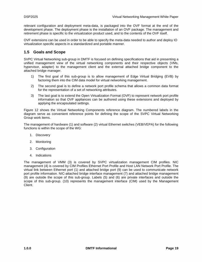
1.5 Goals and Scope
SVPC Virtual Networking sub-group in DMTF is focused on defining specifications that aid in presenting a unified management view of the virtual networking components and their respective objects (VMs, hypervisor, adapter) to the management client and the external attached bridge component to the attached bridge manager.
1) The first goal of this sub-group is to allow management of Edge Virtual Bridging (EVB) by factoring them into the CIM data model for virtual networking management.
2) The second goal is to define a network port profile schema that allows a common data format for the representation of a set of networking attributes.
3) The last goal is to extend the Open Virtualization Format (OVF) to represent network port profile information so that OVF appliances can be authored using these extensions and deployed by applying the encapsulated settings.
Figure 12 shows the Virtual Networking Components reference diagram. The numbered labels in the diagram serve as convenient reference points for defining the scope of the SVPC Virtual Networking Group work items.
The management of hardware (1) and software (2) virtual Ethernet switches (VEB/VEPA) for the following functions is within the scope of the WG:
1. Discovery
2. Monitoring
3. Configuration
4. Indications
The management of VMM (3) is covered by SVPC virtualization management CIM profiles. NIC management (4) is covered by CIM Profiles Ethernet Port Profile and Host LAN Network Port Profile. The virtual link between Ethernet port (1) and attached bridge port (9) can be used to communicate network port profile information. NIC-attached bridge interface management (7) and attached bridge management (9) are outside the scope of this sub-group. Labels (5) and (6) are private interfaces and outside the scope of this sub-group. (10) represents the management interface (CIM) used by the Management Client.
Virtual Networking Management White Paper DSP2025
Page 20 DMTF Informational 1.0.0
Virtualization Layer
VM VMVMVM
VirtLayerMgmt
Virtual Ethernet Switch
Man
agem
ent C
lient
vSwitchManagement
Physical NIC
AdapterMgmt
Virtual Ethernet Switch
VEB/VEPAManagement
Physical Switch
Adjacent Bridge
BridgeManagement
4
7
5
8
1
9
10
6
3 2
Figure 10 – Scope of SVPC Virtual Networking Working Group

DSP2025 Virtual Networking Management White Paper
1.0.0 DMTF Informational Page 21
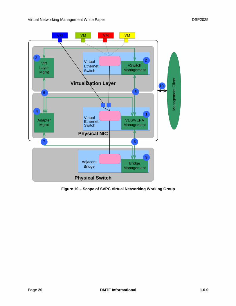
1.6 Relationships to Other DMTF Standards and Specifications
Figure 11 shows the DMTF standards that relate to the modeling of SVPC Virtual networking components. The DMTF standards and corresponding objects of interest to SVPC Virtual networking shown in the figure are listed below:
1. Virtual System Profile (DSP1057)
a. ComputerSystem & VirtualSystemSettingData
b. EnabledLogicalElementCapabilities
2. Ethernet Port Profile (DSP1014)
3. Resource Allocation Profile (DSP1041)
4. Allocation Capabilities Profile (DSP1043)
5. Ethernet Port Resource Virtualization Profile (DSP1050)
a. EthernetPort and LANEndpoint
b. VLANEndpoint & VLANEndPointSettingData
c. EthernetPortAllocationSettingData
6. Virtual Ethernet Switch Profile (DSP1097)
a. ComputerSystem
b. EnabledLogicalElementCapabilities
c. VirtualEthernetSwitchSettingData
d. NetworkVLAN
e. EthernetPort
f. LANEndpoint
g. VLANEndpoint & VLANEndPointSettingData
h. EthernetPortAllocationSettingData
Virtual Networking Management White Paper DSP2025
Page 22 DMTF Informational 1.0.0
pNICS-VLAN Component
A B C E FDD
HW VEB HW VEPA
SW VEB SW VEPA
VM VM VM VM VM VMPhysical
End Station(Host)
Virtual Computer Systems
Direct AccessPhysical
End StationS-Component
DSP1052 Computer System ProfileDSP1057 Virtual System Profile
DSP1014 Ethernet Port ProfileDSP1041 Resource Allocation ProfileDSP1043 Allocation Capabilities ProfileDSP1050 Ethernet Port Resource Virtualization Profile
DSP1097 Virtual Ethernet Switch Profile
Figure 11 – CIM Profiles Related to Virtual Networking
DSP2025 Virtual Networking Management White Paper
1.0.0 DMTF Informational Page 23
2 Virtual Networking Concepts
2.1 Virtual Station Interface (VSI)
VSI is a representation of the networking attributes provided to a VM through a single Ethernet Port attached to a single vNIC, connected to a single Ethernet Port of a vSwitch or a physical NIC (VEB/VEPA). VSI defines vSwitch port behavior and the content exposed to the Hypervisor (not necessarily to a VM or vNIC). VSI uses one Network Port Profile and it may be exposed to the Ethernet Port attached to vNIC (under Hypervisor control).
VSI may support:
• One or more MAC addresses
• Zero or more VLAN tags
• Minimum and Maximum bandwidth settings
• Zero or more traffic priority levels
CIM based model for VSI is described in Ethernet Port Resource Virtualization Profile [ref DSP1050] and Virtual Ethernet Switch Profile [ref DSP1097].
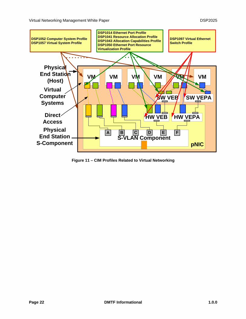
2.2 Virtual Ethernet Bridge (VEB) A hypervisor is a software entity that enables multiple Virtual Machines (VMs) to share common hardware as illustrated in Figure 12. Each VM contains at least one virtual NIC (vNIC) that is associated through the hypervisor with a physical NIC. To create this association, hypervisors have incorporated Virtual Ethernet Bridges (VEB) into the physical end station effectively adding one or more Ethernet switches per end node. A VEB is a frame relay service that supports local bridging between multiple virtual end stations (an internal private virtual network) and (optionally) the external bridging environment.
Figure 12 – Example Hypervisor with Multiple VM, Multiple NIC, attached to an Attached Bridge
A VEB may be implemented in software as a virtual switch (vSwitch) as illustrated in Figure 13 or as embedded hardware within a Network Interface Controller (NIC) as illustrated in Figure 14.
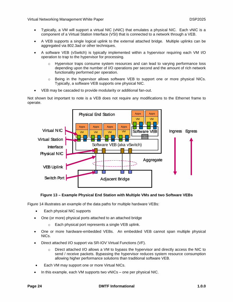
Figure 13 illustrates an example of the data paths for two software VEBs:
• Each VM may support one or more Virtual NICs.
Hypervisor
Physical End Station
Adjacent Bridge
VM
Apps
VM
Apps
VM
Apps
VM
Apps
Switch Port
Physical NIC
Uplink
Ingress Egress
Aggregate
VM
Apps
VM
Apps
Virtual NIC
Hypervisor
Physical End Station
Adjacent Bridge
VM
Apps
VM
Apps
VM
Apps
VM
Apps
Switch Port
Physical NIC
Uplink
Ingress Egress
Aggregate
VM
Apps
VM
Apps
Virtual NIC
Virtual Networking Management White Paper DSP2025
Page 24 DMTF Informational 1.0.0
• Typically, a VM will support a virtual NIC (vNIC) that emulates a physical NIC. Each vNIC is a component of a Virtual Station Interface (VSI) that is connected to a network through a VEB.
• A VEB supports a single logical uplink to the external attached bridge. Multiple uplinks can be aggregated via 802.3ad or other techniques.
• A software VEB (vSwitch) is typically implemented within a hypervisor requiring each VM I/O operation to trap to the hypervisor for processing.
o Hypervisor traps consume system resources and can lead to varying performance loss depending upon the number of I/O operations per second and the amount of rich network functionality performed per operation.
o Being in the hypervisor allows software VEB to support one or more physical NICs. Typically, a software VEB supports one physical NIC.
• VEB may be cascaded to provide modularity or additional fan-out.
Not shown but important to note is a VEB does not require any modifications to the Ethernet frame to operate.
Figure 13 – Example Physical End Station with Multiple VMs and two Software VEBs
Figure 14 illustrates an example of the data paths for multiple hardware VEBs:
• Each physical NIC supports
• One (or more) physical ports attached to an attached bridge
o Each physical port represents a single VEB uplink.
• One or more hardware-embedded VEBs. An embedded VEB cannot span multiple physical NICs.
• Direct attached I/O support via SR-IOV Virtual Functions (VF).
o Direct attached I/O allows a VM to bypass the hypervisor and directly access the NIC to send / receive packets. Bypassing the hypervisor reduces system resource consumption allowing higher performance solutions than traditional software VEB.
• Each VM may support one or more Virtual NICs.
• In this example, each VM supports two vNICs – one per physical NIC.
Software VEB (aka vSwitch)
Physical End Station
Adjacent Bridge
VM
Apps
VM
Apps
VM
Apps
VM
Apps
Virtual Station
Interface
Switch Port
Physical NIC
VEB Uplink
Ingress Egress
Aggregate
*
VM
Apps
VM
Apps
Software VEBVirtual NIC
Software VEB (aka vSwitch)
Physical End Station
Adjacent Bridge
VM
Apps
VM
Apps
VM
Apps
VM
Apps
Virtual Station
Interface
Switch Port
Physical NIC
VEB Uplink
Ingress Egress
Aggregate
*
VM
Apps
VM
Apps
Software VEBVirtual NIC

DSP2025 Virtual Networking Management White Paper
1.0.0 DMTF Informational Page 25
• Each vNIC is a component of a VSI that is associated with a SR-IOV VF to provide Direct attached I/O support.
•
Figure 14 – Example Physical End Station with Multiple Hardware VEBs
Figure 15 – VEB Frame Relay Support
• VEB packet forwarding supports both traditional end station-to-attached bridge as well as local VSI-to-VSI packet forwarding. As illustrated in Figure 15, a VEB forwards packets as follows:
• VEB forwards packets based on the MAC address and optionally via a port group or VLAN identifier.
• VEB forwards packets from a VSI to the uplink from an attached bridge (path 1) or between co-located VSI (path 2)
Physical End Station
Adjacent Bridge
VMApps
VMApps
VMApps
VMApps
IngressEgress
MAC / PHY
Tx/ Rx Queues
PF0 VF1 VFN
VEB
NIC MAC / PHY
Tx/ Rx Queues
PF0 VF1 VFN
VEB
NIC
Virtual Station Interface
Physical NIC
VEB Uplink
VM Direct I/ O via SR-IOV Virtual
FunctionVF2
Physical End Station
Adjacent Bridge
VMApps
VMApps
VMApps
VMApps
IngressEgress
MAC / PHY
Tx/ Rx QueuesMAC /
PHY
Tx/ Rx QueuesMAC /
PHY
Tx/ Rx Queues
PF0 VF1 VFN
VEB
NIC MAC / PHY
Tx/ Rx Queues
PF0 VF1 VFN
VEB
NIC MAC / PHY
Tx/ Rx QueuesMAC /
PHY
Tx/ Rx QueuesMAC /
PHY
Tx/ Rx Queues
PF0 VF1 VFN
VEBPF0 VF1 VFN
VEB
NICPhysical NIC
VEB Uplink
VM Direct I/ O via SR-IOV Virtual
FunctionVF2
Physical End Station
Adjacent Bridge
VMApps
VMApps
VMApps
VMApps
IngressEgress
MAC / PHY
Tx/ Rx QueuesMAC /
PHY
Tx/ Rx QueuesMAC /
PHY
Tx/ Rx Queues
PF0 VF1 VFN
VEB
NIC MAC / PHY
Tx/ Rx Queues
PF0 VF1 VFN
VEB
NIC MAC / PHY
Tx/ Rx QueuesMAC /
PHY
Tx/ Rx QueuesMAC /
PHY
Tx/ Rx Queues
PF0 VF1 VFN
VEBPF0 VF1 VFN
VEB
NIC
Virtual Station Interface
Physical NIC
VEB Uplink
VM Direct I/ O via SR-IOV Virtual
FunctionVF2
Physical End Station
Adjacent Bridge
VMApps
VMApps
VMApps
VMApps
IngressEgress
MAC / PHY
Tx/ Rx QueuesMAC /
PHY
Tx/ Rx QueuesMAC /
PHY
Tx/ Rx QueuesMAC /
PHY
Tx/ Rx Queues
PF0 VF1 VFN
VEB
NIC MAC / PHY
Tx/ Rx QueuesMAC /
PHY
Tx/ Rx QueuesMAC /
PHY
Tx/ Rx Queues
PF0 VF1 VFN
VEBPF0 VF1 VFN
VEB
NIC MAC / PHY
Tx/ Rx QueuesMAC /
PHY
Tx/ Rx QueuesMAC /
PHY
Tx/ Rx QueuesMAC /
PHY
Tx/ Rx Queues
PF0 VF1 VFN
VEBPF0 VF1 VFN
VEB
NICPhysical NIC
VEB Uplink
VM Direct I/ O via SR-IOV Virtual
FunctionVF2
VEB
Physical End Station
Adjacent Bridge
VMApps
VMApps
VMApps
VMApps
Ingress Egress*
expander
VMApps
VMApps
Software VEB
1 2
3
VEB
Physical End Station
Adjacent Bridge
VMApps
VMApps
VMApps
VMApps
Ingress Egress*
expander
VMApps
VMApps
Software VEB
1 2
3
Virtual Networking Management White Paper DSP2025
Page 26 DMTF Informational 1.0.0
o A NIC-embedded VEB can only forward packets between VSI attached to a common NIC. As shown in Figure 14, only VM that share the blue VEB can forward packets via the blue VEB. Similarly, only VM that share the green VEB can forward packets via the green VEB. A VM on the blue VEB cannot forward packets to a VM on the green VEB directly; a software VEB or external bridge would be required to bridge the two NIC-embedded VEBs.
• VEB supports only a single active logical uplink
o Multiple uplinks can be teamed via 802.3ad or other techniques
o Uplink-to-uplink packet forwarding is not allowed (path 3)
• VEB does not participate in or affect spanning tree operation.
VEB provides a number of common benefits and allows hypervisors to:
• Operate without external bridges attached
• Operate with a broad range of Ethernet environments
• Maximize local bandwidth – bandwidth is limited by end station memory and local I/O bandwidth and not by the Ethernet link bandwidth
• Minimize local latency – no incremental latency due to interaction with the external network
• Minimize packet loss, i.e. no packet loss due to external network events – external bridge or link failure, CRC error detection, congestion-based packet loss, etc.
By definition traffic between VMs connected to a VEB stay within the server. Some clients prefer the traffic to be sent through an external switch, so the external network’s access and security policies can be applied to the traffic. To address this type of requirement, Virtual Ethernet Port Aggregator (VEPA) is described next.
2.3 Virtual Ethernet Port Aggregation (VEPA)
A Virtual Ethernet Port Aggregator (VEPA) is a capability within a physical end-station that collaborates with an attached bridge to provide frame relay services between multiple co-located virtual machines (VMs) and the external network. A VEPA collaborates by:
• Forwarding all station-originated frames to the attached bridge for frame processing and frame relay.
• Steering all frames and replicating Multicast and Broadcast frames received from the attached bridge to the appropriate VM destinations.
• A VEPA takes advantage of a special reflective relay forwarding mode (i.e. allow forwarding back out the port a frame was received) on the attached bridge to support inter-VM communication within the same physical host.
o Clause 8.6.1 of Standard IEEE 802.1Q-2005 states that when a switch reception port is in the forwarding state, each switch port in the forwarding state, other than the reception port itself, is a potential transmission port. A VEPA requires an exception to this rule in order to allow inter-VM traffic on the attached host over the single uplink. This exception distinguishes the port attached to a VEPA uplink as a VEPA-enabled port which supports forwarding in reflective relay mode.
• Similar to a VEB, a VEPA may be implemented in software or in conjunction with embedded hardware within a NIC.
• The VEPA is connected to the attached bridge only by a single uplink connection. The connection is attached to a VEPA-enabled port on the attached bridge. A conceptual VEPA is shown in Figure 16.
DSP2025 Virtual Networking Management White Paper
1.0.0 DMTF Informational Page 27
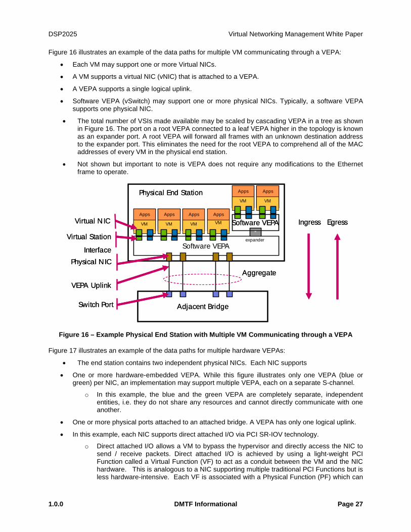
Figure 16 illustrates an example of the data paths for multiple VM communicating through a VEPA:
• Each VM may support one or more Virtual NICs.
• A VM supports a virtual NIC (vNIC) that is attached to a VEPA.
• A VEPA supports a single logical uplink.
• Software VEPA (vSwitch) may support one or more physical NICs. Typically, a software VEPA supports one physical NIC.
• The total number of VSIs made available may be scaled by cascading VEPA in a tree as shown in Figure 16. The port on a root VEPA connected to a leaf VEPA higher in the topology is known as an expander port. A root VEPA will forward all frames with an unknown destination address to the expander port. This eliminates the need for the root VEPA to comprehend all of the MAC addresses of every VM in the physical end station.
• Not shown but important to note is VEPA does not require any modifications to the Ethernet frame to operate.
Figure 16 – Example Physical End Station with Multiple VM Communicating through a VEPA
Figure 17 illustrates an example of the data paths for multiple hardware VEPAs:
• The end station contains two independent physical NICs. Each NIC supports
• One or more hardware-embedded VEPA. While this figure illustrates only one VEPA (blue or green) per NIC, an implementation may support multiple VEPA, each on a separate S-channel.
o In this example, the blue and the green VEPA are completely separate, independent entities, i.e. they do not share any resources and cannot directly communicate with one another.
• One or more physical ports attached to an attached bridge. A VEPA has only one logical uplink.
• In this example, each NIC supports direct attached I/O via PCI SR-IOV technology.
o Direct attached I/O allows a VM to bypass the hypervisor and directly access the NIC to send / receive packets. Direct attached I/O is achieved by using a light-weight PCI Function called a Virtual Function (VF) to act as a conduit between the VM and the NIC hardware. This is analogous to a NIC supporting multiple traditional PCI Functions but is less hardware-intensive. Each VF is associated with a Physical Function (PF) which can
Software VEPA
Physical End Station
Adjacent Bridge
VM
Apps
VM
Apps
VM
Apps
VM
Apps
Virtual Station
Interface
Switch Port
Physical NIC
VEPA Uplink
Ingress Egress
Aggregate
*expander
VM
Apps
VM
Apps
Software VEPAVirtual NIC
Software VEPA
Physical End Station
Adjacent Bridge
VM
Apps
VM
Apps
VM
Apps
VM
Apps
Virtual Station
Interface
Switch Port
Physical NIC
VEPA Uplink
Ingress Egress
Aggregate
*expander
VM
Apps
VM
Apps
Software VEPAVirtual NIC

Virtual Networking Management White Paper DSP2025
Page 28 DMTF Informational 1.0.0
be used by the hypervisor as a management conduit to provide overall control of the device or the port depending upon the implementation.
• Each VM may support one or more Virtual NICs.
• In this example, each VM supports two vNICs – one per physical NIC.
• Each vNIC contains a VSI which is associated with a SR-IOV VF to provide the direct attached I/O conduit.
Figure 17 – VEPA Frame Relay Support
As illustrated in Figure 17, a VEPA forwards packets as follows:
• VEPA forwards packets based on the MAC address and optionally via a port group or VLAN identifier.
• All VEPA traffic must be forwarded from the VSI to the uplink of an attached bridge (path 1).
o VSI-to-VSI packet forwarding is not allowed (path 2).
• A VEPA supports only a single active logical uplink
o Uplink-to-uplink packet forwarding is not allowed (path 3)
o A VEPA may be partitioned into multiple logical VEPA each associated with its own independent uplink.
• A VEPA does not participate in or affect spanning tree operation.
Based on the prior materials, the reader should note the significant overlap in functionality and potential implementation between a VEB and a VEPA with the primary difference occurring in frame relay support. Further, this difference determines where and how network features are surfaced and their associated impact on system functional robustness and performance. This difference allows VEPA solutions to provide the following benefits:
1. Enables a consistent level of network policy enforcement by routing all network traffic through the attached bridge with its more complete policy-enforcement capabilities.
2. Provides visibility of inter-VM traffic to network management tools designed for attached bridge.
VEPA
Physical End Station
Adjacent Bridge
VMApps
VMApps
VMApps
VMApps
Ingress Egress*
expander
VMApps
VMApps
Software VEPA
1 2
3
VEPA
Physical End Station
Adjacent Bridge
VMApps
VMApps
VMApps
VMApps
Ingress Egress*
expander
VMApps
VMApps
Software VEPA
1 2
3
DSP2025 Virtual Networking Management White Paper
1.0.0 DMTF Informational Page 29
3. Reduces the amount of network configuration required by server administrators, and as a consequence, reduces the complexity for the network administrator.
4. Can increase solution performance by off-loading advanced network functionality that may be computationally intensive to implement within a hypervisor or VM to the attached bridge.
5. Enables off-loading advanced network functions from the VM or hypervisor to the attached bridge.
6. Allows NICs to be simpler by leveraging advanced functions on the attached bridge.
As it can be seen, a VEPA provides a number of benefits but it has the following limitations:
• Promiscuous support – To support a promiscuous VSI, a VEPA address table must be configured with all VM source MAC addresses. This requires either adding MAC address learning support or provisioning large address tables. Either option adds implementation cost and complexity.
• Support for simultaneous VEB, VEPA, and directly accessible ports on the same physical link – The attached bridge can only process a frame based on its contents and therefore lacks sufficient information to delineate between these three operating modes.
• Hierarchy of unrestricted physical ports – Supporting the number of source MAC addresses that exceeds the size of VEPA address table is not permitted.
Virtual Networking Management White Paper DSP2025
Page 30 DMTF Informational 1.0.0
3 CIM Classes for Virtual Networking Components DMTF has defined a number of CIM classes to address the management of virtual networking components.
The following networking components are modeled using the CIM.
• Virtual NIC within a VM (vNIC or VM NIC or vmnic)
• Virtual Ethernet Switch(es) (vSwitch and eSwitch) within a Virtualization Platform
• Virtual Ethernet Ports of vNICs and virtual Ethernet switches
• Host Ethernet Ports (Ethernet ports on the physical NIC)
• Connections between vNIC Ethernet Ports and virtual Ethernet switch Ports
• Connections between virtual Ethernet Ports and Host Ethernet Ports
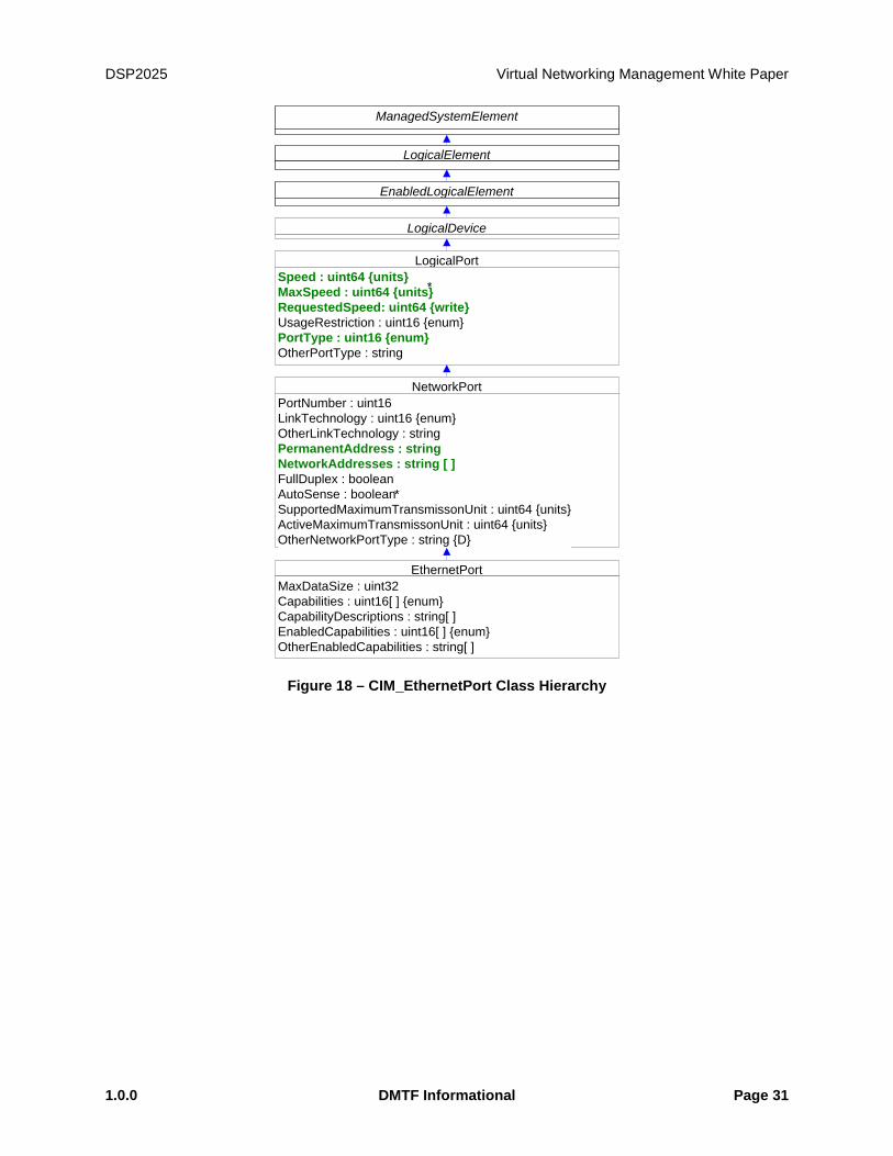
3.1 Ethernet Port
A single vNIC inside a VM is represented by an instance of CIM_EthernetPort. A vNIC within a VM is configured with one or multiple MAC addresses and zero or more access VLANs.
An EthernetPort instance is also used to represent each Ethernet Switch port on a vSwitch or eSwitch.
The allocation of Ethernet port instances to a VM or a virtual Ethernet switch including bandwidth reservation/allocation is modeled in Ethernet Port Resource Virtualization Profile (DSP1050).
Figure 18, Figure 19 and Figure 20 below show the class definitions of CIM_EthernetPort, CIM_LANEndPoint, CIM_VLANEndPoint, and CIM_VLANEndPointSettingData.
DSP2025 Virtual Networking Management White Paper
1.0.0 DMTF Informational Page 31
*
LogicalDevice
LogicalPortSpeed : uint64 {units}MaxSpeed : uint64 {units}RequestedSpeed: uint64 {write}UsageRestriction : uint16 {enum}PortType : uint16 {enum}OtherPortType : string
*
EthernetPortMaxDataSize : uint32Capabilities : uint16[ ] {enum}CapabilityDescriptions : string[ ]EnabledCapabilities : uint16[ ] {enum}OtherEnabledCapabilities : string[ ]
NetworkPortPortNumber : uint16LinkTechnology : uint16 {enum}OtherLinkTechnology : stringPermanentAddress : stringNetworkAddresses : string [ ]FullDuplex : booleanAutoSense : booleanSupportedMaximumTransmissonUnit : uint64 {units}ActiveMaximumTransmissonUnit : uint64 {units}OtherNetworkPortType : string {D}
*
LogicalElement
ManagedSystemElement
EnabledLogicalElement
Figure 18 – CIM_EthernetPort Class Hierarchy

Virtual Networking Management White Paper DSP2025
Page 32 DMTF Informational 1.0.0
*
ServiceAccessPoint
*
*
LogicalElement
ManagedSystemElement
EnabledLogicalElement
ProtocolEndPoint
LANEndpointLANID: string LANType: uint16 {D, enum}OtherLANType: string {D}MACAddress: stringAliasAddresses: string[]GroupAddresses: string[]MaxDataSize: uint32 {units}
VLANEndpointOtherEndpointMode: uint16 {enum}DesiredEndpointMode: uint16 {enum}OperationalEndpointMode: uint16 {enum}OtherTrunkEncapsulation: uint16 {enum}OperationalVLANTrunkEncapsulation: uint16 {enum} GVRPStatus: uint16 {enum}
EthernetPort
DeviceSAPImplementation
Figure 19 – CIM_LANEndPoint and CIM_VLANEndPoint Classes
(See Core Model)Collection
(See Core Model)
ManagedElement
(See Core Model)SystemSpecificCollection
(See Network Model (Collections))ConnectivityCollection
(See Core Model)SettingData
NetworkVLAN
VLANId: uint16MaxTransmissionSize: sint32SAIdentifier: unit32TypeOfMedia: uint 16OtherTypeDescription: string
VLANSystemSettingData
ReservedVLANList: uint16[ ]InternalVLANList: uint16[ ]NumberOfConfiguredVLANs: uint16DynamicVLANList: uint16[ ]StaticVLANList: uint16[ ]
VLANEndpointSettingData
PruneEligibleVLANList: uint16[ ]Native VLAN: uint16Default VLAN: uint16TunkedVLANList: uint16[ ]AccessVLAN: uint16
Figure 20 – CIM_VLANEndpointSettingData and CIM_NetworkVLAN Classes
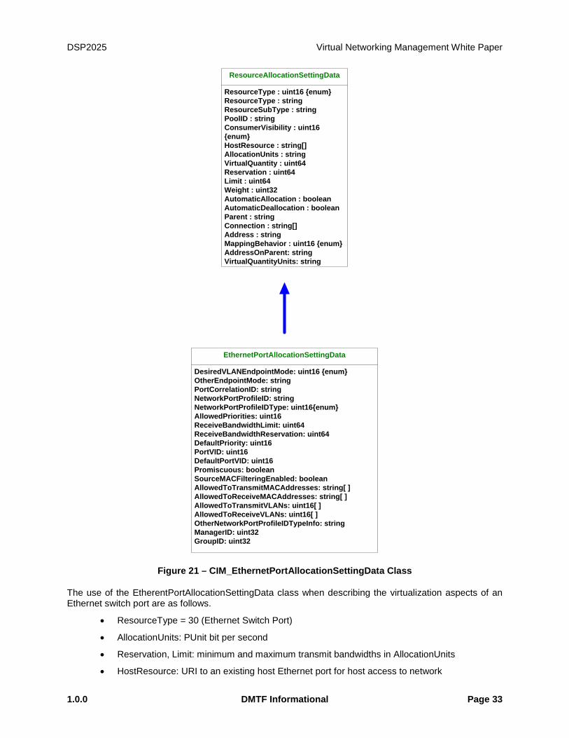
3.2 Ethernet Port Resource Virtualization
Figure 21 shows the class definition of EthernetPortAllocationSettingData.
DSP2025 Virtual Networking Management White Paper
1.0.0 DMTF Informational Page 33
ResourceAllocationSettingData
ResourceType : uint16 {enum}ResourceType : stringResourceSubType : stringPoolID : stringConsumerVisibility : uint16 {enum}HostResource : string[]AllocationUnits : stringVirtualQuantity : uint64Reservation : uint64Limit : uint64Weight : uint32AutomaticAllocation : booleanAutomaticDeallocation : booleanParent : stringConnection : string[]Address : stringMappingBehavior : uint16 {enum}AddressOnParent: stringVirtualQuantityUnits: string
EthernetPortAllocationSettingData
DesiredVLANEndpointMode: uint16 {enum}OtherEndpointMode: stringPortCorrelationID: stringNetworkPortProfileID: stringNetworkPortProfileIDType: uint16{enum}AllowedPriorities: uint16ReceiveBandwidthLimit: uint64ReceiveBandwidthReservation: uint64DefaultPriority: uint16PortVID: uint16DefaultPortVID: uint16Promiscuous: booleanSourceMACFilteringEnabled: booleanAllowedToTransmitMACAddresses: string[ ]AllowedToReceiveMACAddresses: string[ ]AllowedToTransmitVLANs: uint16[ ]AllowedToReceiveVLANs: uint16[ ]OtherNetworkPortProfileIDTypeInfo: stringManagerID: uint32GroupID: uint32
Figure 21 – CIM_EthernetPortAllocationSettingData Class
The use of the EtherentPortAllocationSettingData class when describing the virtualization aspects of an Ethernet switch port are as follows.
• ResourceType = 30 (Ethernet Switch Port)
• AllocationUnits: PUnit bit per second
• Reservation, Limit: minimum and maximum transmit bandwidths in AllocationUnits
• HostResource: URI to an existing host Ethernet port for host access to network
Virtual Networking Management White Paper DSP2025
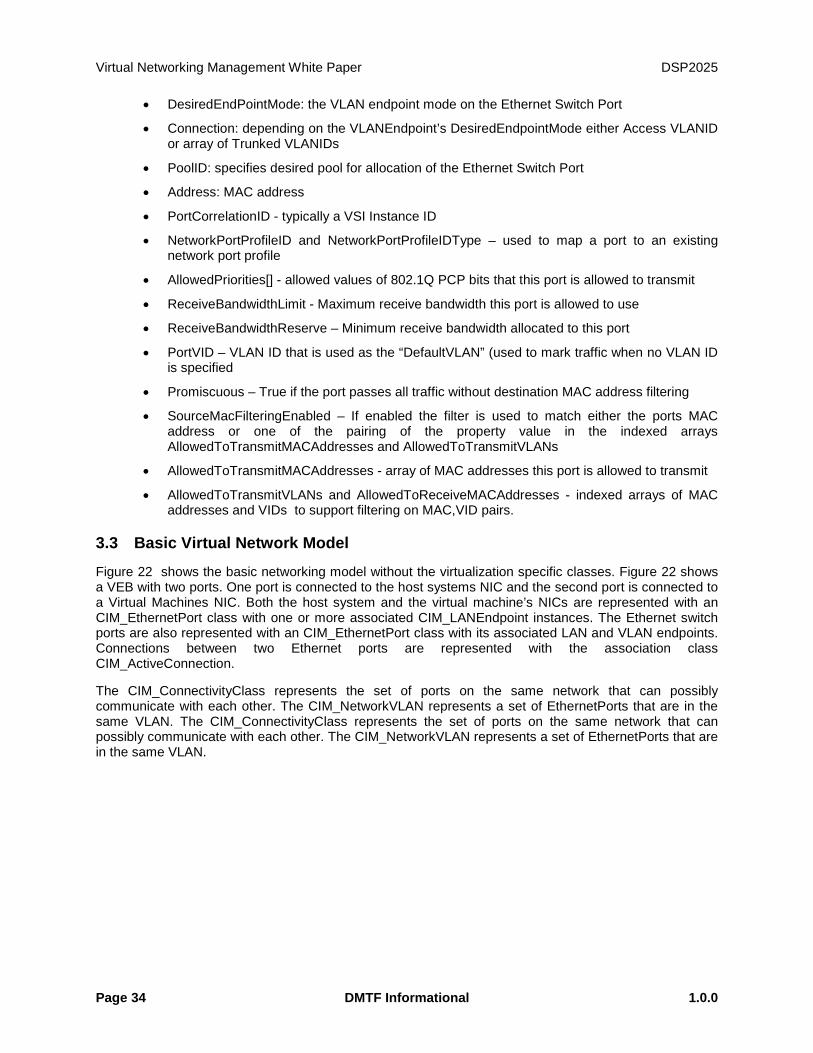
Page 34 DMTF Informational 1.0.0
• DesiredEndPointMode: the VLAN endpoint mode on the Ethernet Switch Port
• Connection: depending on the VLANEndpoint’s DesiredEndpointMode either Access VLANID or array of Trunked VLANIDs
• PoolID: specifies desired pool for allocation of the Ethernet Switch Port
• Address: MAC address
• PortCorrelationID - typically a VSI Instance ID
• NetworkPortProfileID and NetworkPortProfileIDType – used to map a port to an existing network port profile
• AllowedPriorities[] - allowed values of 802.1Q PCP bits that this port is allowed to transmit
• ReceiveBandwidthLimit - Maximum receive bandwidth this port is allowed to use
• ReceiveBandwidthReserve – Minimum receive bandwidth allocated to this port
• PortVID – VLAN ID that is used as the “DefaultVLAN” (used to mark traffic when no VLAN ID is specified
• Promiscuous – True if the port passes all traffic without destination MAC address filtering
• SourceMacFilteringEnabled – If enabled the filter is used to match either the ports MAC address or one of the pairing of the property value in the indexed arrays AllowedToTransmitMACAddresses and AllowedToTransmitVLANs
• AllowedToTransmitMACAddresses - array of MAC addresses this port is allowed to transmit
• AllowedToTransmitVLANs and AllowedToReceiveMACAddresses - indexed arrays of MAC addresses and VIDs to support filtering on MAC,VID pairs.
3.3 Basic Virtual Network Model
Figure 22 shows the basic networking model without the virtualization specific classes. Figure 22 shows a VEB with two ports. One port is connected to the host systems NIC and the second port is connected to a Virtual Machines NIC. Both the host system and the virtual machine’s NICs are represented with an CIM_EthernetPort class with one or more associated CIM_LANEndpoint instances. The Ethernet switch ports are also represented with an CIM_EthernetPort class with its associated LAN and VLAN endpoints. Connections between two Ethernet ports are represented with the association class CIM_ActiveConnection.
The CIM_ConnectivityClass represents the set of ports on the same network that can possibly communicate with each other. The CIM_NetworkVLAN represents a set of EthernetPorts that are in the same VLAN. The CIM_ConnectivityClass represents the set of ports on the same network that can possibly communicate with each other. The CIM_NetworkVLAN represents a set of EthernetPorts that are in the same VLAN.

DSP2025 Virtual Networking Management White Paper
1.0.0 DMTF Informational Page 35
Virtual Machine
DeviceSAPImplementation
Host SystemSystem
-VS1-Dedicated = 38 (EthernetSwitch)
ComputerSystem
EthernetPortDeviceSAP Implementation
LANEndpointSystemDevice
LANEndpoint
EthernetPort
ComputerSystem
DeviceSAP Implementation
SystemDevice
VLANEndpointBindsToLanEndpoint
-VLANID = VLANID0NetworkVLAN
HostedCollection
MemberOfCollection
HostedCollection
LANEndpoint
EthernetPort
DeviceSAP Implementation
SystemDevice
MemeberOfCollection
Virtual Ethernet Bridge
Host System
EthernetPortLANEndpoint
ActiveConnection
VLANEndpoint
BindsToLanEndpoint
SystemDevice
ActiveConnection
ConnectivityCollection
Figure 22 – Basic CIM Network Model
3.4 Virtual Ethernet Switch
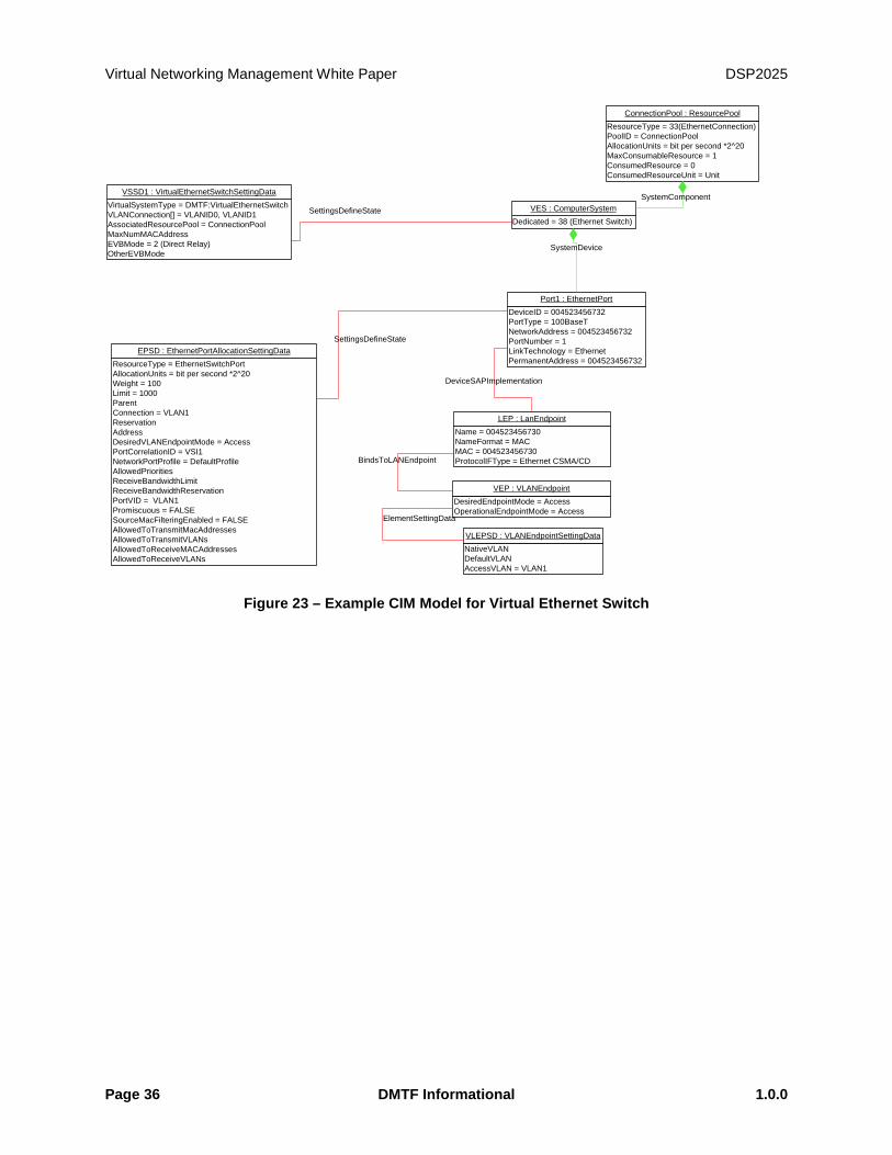
A virtual Ethernet switch is modeled as a specialized virtual computer system as described in DSP1097 (Virtual Ethernet Switch Profile.) The basic vSwitch model is an instance of CIM_ComputerSystem and an associated set of Ethernet port instances and their associated virtualization components: CIM_VirtualEthernetSwitchSettingData and CIM_EthernetPortAllocationSettingData. As virtual Ethernet switches are specialized virtual systems as defined in DSP1057 Virtual System Profile they are managed as described in DSP1042 (System Virtualization Profile).
Figure 23 is an example CIM representation of a virtual Ethernet switch with one Ethernet switch port. VES represents the switch. VSSD1 represents the state configuration of the vSwitch, defining the virtualization aspects of the switch. This switch is a virtual Ethernet bridge (Direct Relay). VSSD1.AssoicatedResourcePool is used to associate ConnectionPool to this switch to describe the characteristics of the allocatable virtual Ethernet switch ports.
Virtual Networking Management White Paper DSP2025
Page 36 DMTF Informational 1.0.0
Figure 23 – Example CIM Model for Virtual Ethernet Switch
DeviceID = 004523456732PortType = 100BaseTNetworkAddress = 004523456732PortNumber = 1LinkTechnology = EthernetPermanentAddress = 004523456732
Port1 : EthernetPort
Name = 004523456730NameFormat = MACMAC = 004523456730ProtocolIFType = Ethernet CSMA/CD
LEP : LanEndpoint
DeviceSAPImplementation
NativeVLANDefaultVLANAccessVLAN = VLAN1
VLEPSD : VLANEndpointSettingData
DesiredEndpointMode = AccessOperationalEndpointMode = Access
VEP : VLANEndpoint
Dedicated = 38 (Ethernet Switch)VES : ComputerSystem
SystemDevice
ResourceType = EthernetSwitchPortAllocationUnits = bit per second *2^20Weight = 100Limit = 1000ParentConnection = VLAN1ReservationAddressDesiredVLANEndpointMode = AccessPortCorrelationID = VSI1NetworkPortProfile = DefaultProfileAllowedPrioritiesReceiveBandwidthLimitReceiveBandwidthReservationPortVID = VLAN1Promiscuous = FALSESourceMacFilteringEnabled = FALSEAllowedToTransmitMacAddressesAllowedToTransmitVLANsAllowedToReceiveMACAddressesAllowedToReceiveVLANs
EPSD : EthernetPortAllocationSettingDataSettingsDefineState
BindsToLANEndpoint
ElementSettingData
VirtualSystemType = DMTF:VirtualEthernetSwitchVLANConnection[] = VLANID0, VLANID1AssociatedResourcePool = ConnectionPoolMaxNumMACAddressEVBMode = 2 (Direct Relay)OtherEVBMode
VSSD1 : VirtualEthernetSwitchSettingData
SettingsDefineState
ResourceType = 33(EthernetConnection)PoolID = ConnectionPoolAllocationUnits = bit per second *2^20MaxConsumableResource = 1ConsumedResource = 0ConsumedResourceUnit = Unit
ConnectionPool : ResourcePool
SystemComponent
DSP2025 Virtual Networking Management White Paper
1.0.0 DMTF Informational Page 37
4 Management Use Cases for Virtual Networking Based on the CIM classes and profiles that are defined in the DMTF, a rich set of virtual networking management use cases can be covered. This section summarizes a set of important management use cases that are covered by the DMTF CIM profiles for the virtual networking.
4.1 Virtual NIC Management
The virtual NIC that is represented by an Ethernet Port can be managed using Ethernet Port Profile and Ethernet Port Resource Virtualization Profile.
4.1.1 Use Cases Covered By Ethernet Port Profile
1. Get Ethernet Port settings
a. MAC address, Speed, duplex setting, MTU…
2. Modify Ethernet Port Settings
a. MAC address, Speed, duplex setting, MTU…
3. Determine Physical Connector for an Ethernet Address
4. Determining If Physical Communication Is Possible
5. Correlating a Controller and an Ethernet Port
6. Adding an Endpoint to the Ethernet Port
4.1.2 Use Cases Covered By Ethernet Port Resource Virtualization Profile
1. Static Ethernet Switch Port and Ethernet Connection Resource Pools with Capabilities
2. Static Ethernet switch port allocation to a Virtual Ethernet Switch
3. Allocation and connection of an Ethernet adapter to a static switch port
4. Connection of an Ethernet Adapter to an Ethernet switch (dynamic switch port allocation)
5. Ethernet connection of a virtual system to a virtual switch (simple switch port allocation)
6. Inspect the set of Ethernet Adapter of an active virtual system including their connection to an Ethernet switch port
7. Inspect the set of Ethernet switch ports of an active virtual Ethernet Switch including the connection between the switch ports and virtual systems
8. Connection of an Ethernet Adapter to a static Ethernet switch port
9. Connection of an Ethernet Adapter to a dynamic Ethernet switch port
4.1.3 Use Cases for EVB Settings Management
1. Get vNIC settings for EVB
a. Bandwidth reservation (min and max)
b. Lossless service
c. VLAN setting
Virtual Networking Management White Paper DSP2025
Page 38 DMTF Informational 1.0.0
2. …..Modify vNIC settings for EVB
a. Bandwidth reservation (min and max)
b. Lossless service
c. VLAN setting
4.2 Virtual Ethernet Switch Management
A vSwitch or eSwitch is represented as a computer system in Virtual Ethernet Switch Profile (DSP1097). The following use cases are covered by the Virtual Ethernet Switch Profile.
1) Create a Virtual Ethernet Switch on a virtualization platform
2) Determine Virtual Ethernet Switch and its relationship to a virtualization platform’s host system
3) Discover Virtual Ethernet Switches in a virtualization platform
4) Get Virtual Ethernet Switch Settings
5) Modify Virtual Ethernet Switch Settings
6) Inspect the set of active virtual systems connected to a target virtual Ethernet switch
7) Static Ethernet switch port allocation to a Virtual Ethernet Switch
8) Allocation and connection of an Ethernet adapter to a static switch port
9) Connection of an Ethernet Adapter to an Ethernet switch (dynamic switch port allocation)
10) Ethernet connection of a virtual system to a virtual switch (simple switch port allocation)
11) Inspect the set of Ethernet Adapter of an active virtual system including their connection to an Ethernet switch port
12) Inspect the set of Ethernet switch ports of an active virtual Ethernet Switch including the connection between the switch ports and virtual systems
13) Connection of an Ethernet Adapter to a static Ethernet switch port
14) Connection of an Ethernet Adapter to a dynamic Ethernet switch port
4.2.1 Use Cases for EVB Management
1) Get Inventory of Virtual Ethernet Switches on a virtualization platform
a. Number of Virtual Ethernet Switches
b. EVB Modes of each Virtual Ethernet Switch: VEB or VEPA
2) Get current EVB modes of a Virtual Ethernet Switch
3) Modify EVB modes of a Virtual Ethernet Switch
4) Get settings of the Ethernet Switch Port
a. Bandwidth allocated,
b. Lossless service enabled/disabled,
c. VLAN setting…
DSP2025 Virtual Networking Management White Paper
1.0.0 DMTF Informational Page 39
5) Modify settings of the Ethernet Switch Port
a. Bandwidth allocated
b. Lossless service enabled/disabled
c. VLAN setting…
4.3 Lifecycle Operations for Example Use Cases
The operational use cases described in the first two sub-sections of this section can be used to perform lifecycle operations on virtual networking components. This sub-section describes lifecycle operations for example use cases.
4.3.1 Use Cases
The following is a list of some example high-level use cases:
4.3.2 Use Case 1
Figure 24 shows the data and control model for Use Case 1 where VEBs instantiated in software by the hypervisor are used. Figure 26 shows the conceptual model for Use Case 1, while Figure 30 shows the CIM Connectivity model with its classes described in DSP1097 and DSP1050. This diagram does not consider profile boundaries. Classes representing the physical adapter are described in DSP1014.
4.3.3 Use Case 2
Figure 25 shows the data model for Use Case 2 where the VEBs embedded as part of the NIC hardware are used and there are no software VEBs. Figure 28 show the conceptual for Use Case 2 while Figure 29 shows the corresponding CIM Connectivity model with its classes. Note that there is no vSwitch in this model. Classes representing vNIC are described in DSP1097 and DSP1050. In this use case the VM’s vNIC connects directly with the eSwitch. Classes representing the physical adapter are described in DSP1014.
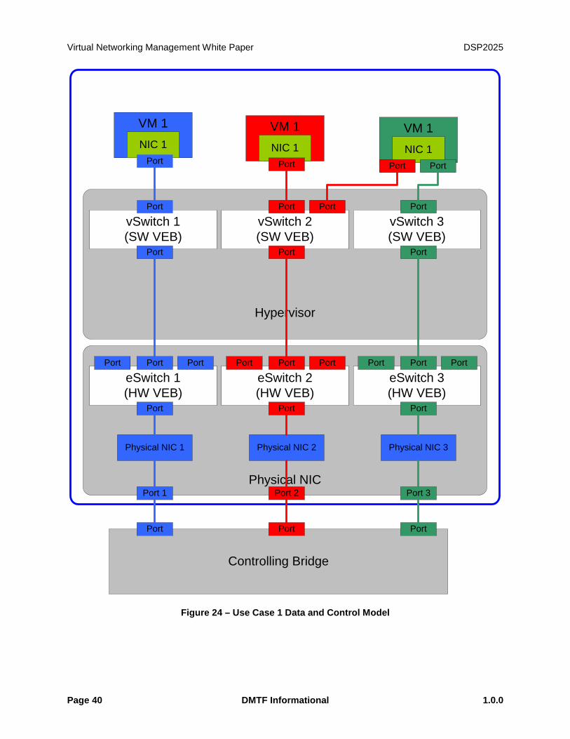
Virtual Networking Management White Paper DSP2025
Page 40 DMTF Informational 1.0.0
Hypervisor
Physical NIC
eSwitch 1(HW VEB)
Port Port Port
Port
eSwitch 2(HW VEB)
Port Port Port
Port
eSwitch 3(HW VEB)
Port Port Port
Port
vSwitch 1(SW VEB)
Port
Port
vSwitch 2(SW VEB)
Port Port
Port
vSwitch 3(SW VEB)
Port
Port
Controlling Bridge
Port 1 Port 2 Port 3
Physical NIC 1 Physical NIC 3Physical NIC 2
Port Port Port
VM 1NIC 1
Port
VM 1NIC 1
Port
VM 1NIC 1
Port Port
Figure 24 – Use Case 1 Data and Control Model
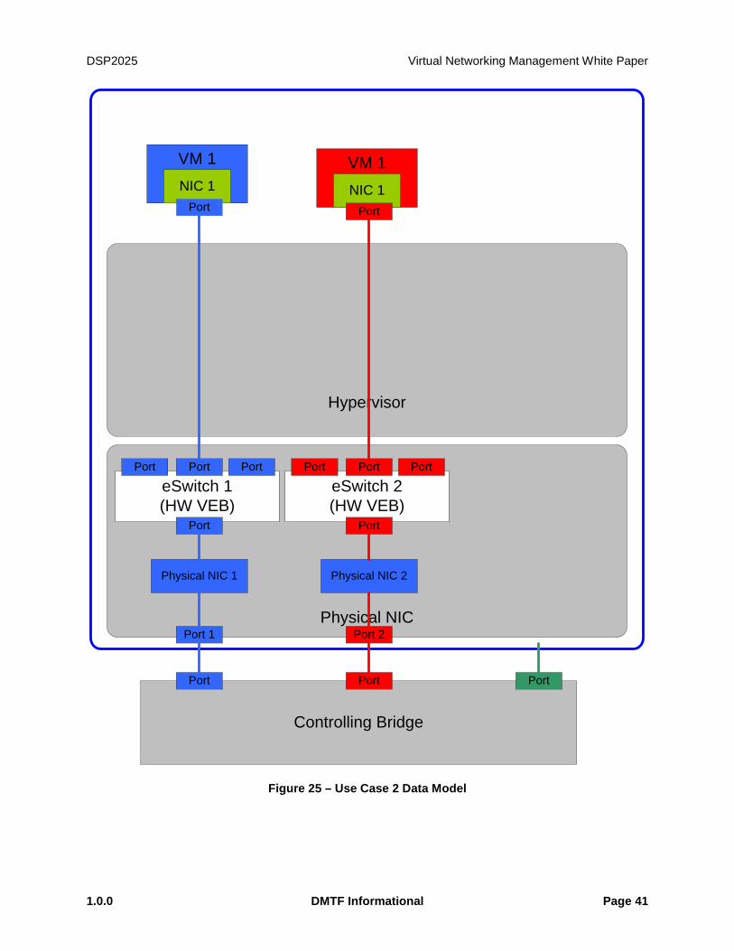
DSP2025 Virtual Networking Management White Paper
1.0.0 DMTF Informational Page 41
Hypervisor
Physical NIC
eSwitch 1(HW VEB)
Port Port Port
Port
eSwitch 2(HW VEB)
Port Port Port
Port
Controlling Bridge
Port 1 Port 2
Physical NIC 1 Physical NIC 2
Port Port Port
VM 1NIC 1
Port
VM 1NIC 1
Port
Figure 25 – Use Case 2 Data Model
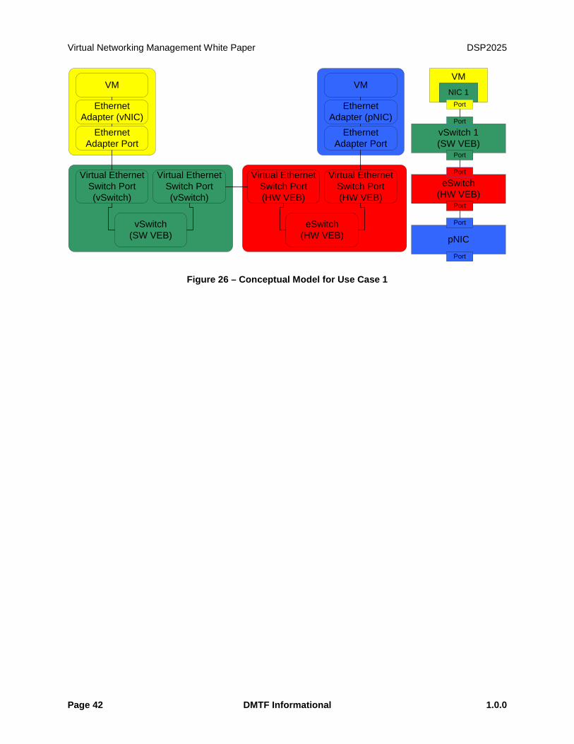
Virtual Networking Management White Paper DSP2025
Page 42 DMTF Informational 1.0.0
VM
EthernetAdapter (vNIC)
Ethernet Adapter Port
VM
EthernetAdapter (pNIC)
Ethernet Adapter Port
Virtual EthernetSwitch Port(vSwitch)
Virtual EthernetSwitch Port(vSwitch)
vSwitch(SW VEB)
Virtual EthernetSwitch Port(HW VEB)
Virtual EthernetSwitch Port(HW VEB)
eSwitch(HW VEB)
vSwitch 1(SW VEB)
Port
Port
VMNIC 1
Port
eSwitch(HW VEB)
Port
Port
pNIC
Port
Port
Figure 26 – Conceptual Model for Use Case 1
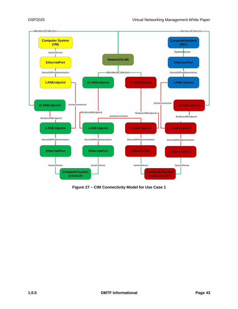
DSP2025 Virtual Networking Management White Paper
1.0.0 DMTF Informational Page 43
VLANEndpoint VLANEndpoint LANEndpoint
Computer System(VM)
LANEndpoint LANEndpoint
EthernetPort
VLANEndpoint VLANEndpoint
LANEndpoint LANEndpoint
ComputerSystem(NIC)
NetworkVLAN
EthernetPort EthernetPort EthernetPort EthernetPort
ComputerSystem(vSwitch)
ComputerSystemHardware VEB
SystemDevice SystemDevice SystemDevice SystemDevice
MemberofCollection
MemberofCollection MemberofCollection
LANEndpoint
EthernetPort
SystemDevice
DeviceSAPImplementation DeviceSAPImplementation
BindstoLANEndpoint BindstoLANEndpoint
ActiveConnection
BindstoLANEndpoint BindstoLANEndpoint
DeviceSAPImplementation DeviceSAPImplementation DeviceSAPImplementation DeviceSAPImplementation
SystemDevice
ActiveConnection
ActiveConnection
Figure 27 – CIM Connectivity Model for Use Case 1

Virtual Networking Management White Paper DSP2025
Page 44 DMTF Informational 1.0.0
VM
Ethernet Adaptor Port
Ethernet Adaptor(vNIC)
NIC
Ethernet Adaptor Port
Ethernet Adaptor(pNIC)
pNIC
Virtual Ethernet Switch Port
Hardware VEB
eSwitchHardware VEB
Virtual Ethernet Switch Port
Hardware VEB
eSwitch
VM
vNIC
Figure 28 – Conceptual Model for Use Case 2
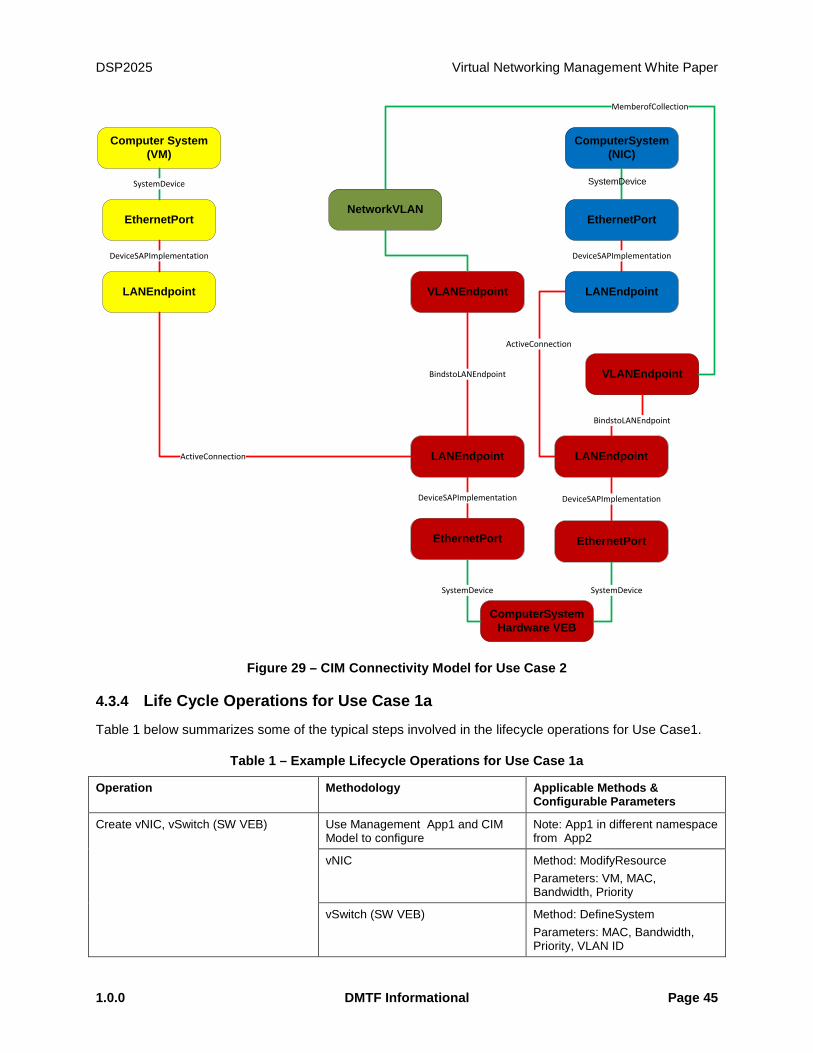
DSP2025 Virtual Networking Management White Paper
1.0.0 DMTF Informational Page 45
VLANEndpoint LANEndpoint
Computer System(VM)
LANEndpoint
EthernetPort
VLANEndpoint
LANEndpoint
ComputerSystem(NIC)
NetworkVLAN
EthernetPort EthernetPort
ComputerSystemHardware VEB
SystemDevice SystemDevice
MemberofCollection
LANEndpoint
EthernetPort
SystemDevice
DeviceSAPImplementation DeviceSAPImplementation
BindstoLANEndpoint
ActiveConnection
ActiveConnection
BindstoLANEndpoint
DeviceSAPImplementation DeviceSAPImplementation
SystemDevice
Figure 29 – CIM Connectivity Model for Use Case 2
4.3.4 Life Cycle Operations for Use Case 1a
Table 1 below summarizes some of the typical steps involved in the lifecycle operations for Use Case1.
Table 1 – Example Lifecycle Operations for Use Case 1a
Operation Methodology Applicable Methods & Configurable Parameters
Create vNIC, vSwitch (SW VEB) Use Management App1 and CIM Model to configure
Note: App1 in different namespace from App2
vNIC Method: ModifyResource Parameters: VM, MAC, Bandwidth, Priority
vSwitch (SW VEB) Method: DefineSystem Parameters: MAC, Bandwidth, Priority, VLAN ID
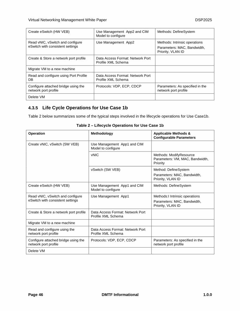
Virtual Networking Management White Paper DSP2025
Page 46 DMTF Informational 1.0.0
Create eSwitch (HW VEB) Use Management App2 and CIM Model to configure
Methods: DefineSystem
Read vNIC, vSwitch and configure eSwitch with consistent settings
Use Management App2 Methods: Intrinsic operations Parameters: MAC, Bandwidth, Priority, VLAN ID
Create & Store a network port profile Data Access Format: Network Port Profile XML Schema
Migrate VM to a new machine
Read and configure using Port Profile DB
Data Access Format: Network Port Profile XML Schema
Configure attached bridge using the network port profile
Protocols: VDP, ECP, CDCP Parameters: As specified in the network port profile
Delete VM
4.3.5 Life Cycle Operations for Use Case 1b
Table 2 below summarizes some of the typical steps involved in the lifecycle operations for Use Case1b.
Table 2 – Lifecycle Operations for Use Case 1b
Operation Methodology Applicable Methods & Configurable Parameters
Create vNIC, vSwitch (SW VEB)
Use Management App1 and CIM Model to configure
vNIC Methods: ModifyResource Parameters: VM, MAC, Bandwidth, Priority
vSwitch (SW VEB) Method: DefineSystem Parameters: MAC, Bandwidth, Priority, VLAN ID
Create eSwitch (HW VEB) Use Management App1 and CIM Model to configure
Methods: DefineSystem
Read vNIC, vSwitch and configure eSwitch with consistent settings
Use Management App1 Methods:I Intrinsic operations Parameters: MAC, Bandwidth, Priority, VLAN ID
Create & Store a network port profile Data Access Format: Network Port Profile XML Schema
Migrate VM to a new machine
Read and configure using the network port profile
Data Access Format: Network Port Profile XML Schema
Configure attached bridge using the network port profile
Protocols: VDP, ECP, CDCP Parameters: As specified in the network port profile
Delete VM
DSP2025 Virtual Networking Management White Paper
1.0.0 DMTF Informational Page 47
5 Network Port Profile XML Schema A Network Port Profile refers to a set of networking attributes that can be applied to one or more virtual machines. The application of network port profile to a virtual machine results in a specific configuration of the network infrastructure to which the virtual machine gets connected to.
5.1 Network Port-Profile XML Schema
The Network Port-Profile XML schema defines the structure of Network Port Profile XML documents. The network port profile XML schema leverages the properties of EthernetPortAllocationSettingData to provide a common way to represent the elements of network port profiles. The use of properties of EthernetPortAllocationSettingData to represent the standard elements of network port profile enables a consistent representation of network attributes during the packaging, deployment, and runtime management of networking attributes. The Network Port Profile XML schema is also extensible as it allows the incorporation of other elements that are not derived from the properties of EthernePortAllocationSettingData. The Network Port Profile XML Schema can be used to represent the following networking attributes including:
1. Network Port Profile Identifier
2. MAC addresses
3. VLANs
4. MAC Address/VLAN pairs
5. Traffic priority
6. Flow control
7. Bandwidth settings
8. Access Control Lists (ACLs)
The above list is for illustrative purposes, there may be additional networking attributes that could be represented by the Network Port Profiles. Appendix A contains some examples of potential Network Port Profile XML elements.
5.2 Network Port Profile Representation in OVF
OVF provides an extensible format for packaging and distribution of the VMs. OVF supports the representation of configuration of single VM or multiple VMs. This section covers the representation of virtual networking attributes in OVF.
The network port profiles can be incorporated in an OVF package in at least three different ways as described below:
1. The OVF package contains one or more network port profiles inside the package as separate XML documents and the OVF file inside the package contains the references to the network port profiles that apply to one or more virtual computer systems represented in the OVF file.
2. The OVF package contains the network port profiles or elements of network port profiles embedded inside the OVF file of the package. The embedded network port profile information applies to one or more virtual computer systems represented in the OVF file.
3. The OVF package contains the references to one or more network port profiles that are not contained inside the package. For example, the package uses URIs to reference the network
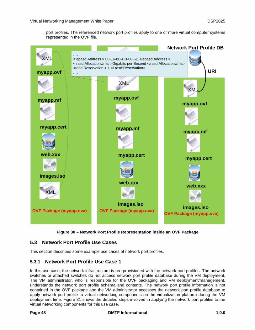
Virtual Networking Management White Paper DSP2025
Page 48 DMTF Informational 1.0.0
port profiles. The referenced network port profiles apply to one or more virtual computer systems represented in the OVF file.
OVF Package (myapp.ova)
myapp.ovf
XML
web.xxx
images.iso
myapp.mf
myapp.cert
XML
OVF Package (myapp.ova)
myapp.ovf
XML
web.xxx
images.iso
myapp.mf
myapp.cert
OVF Package (myapp.ova)
myapp.ovf
XML
web.xxx
images.iso
myapp.mf
myapp.cert
Network Port Profile DB
URI
….< epasd:Address > 00-16-8B-DB-00-5E </epasd:Address >< rasd:AllocationUnits >Gigabits per Second </rasd:AllocationUnits><rasd:Reservation > 1 </ rasd:Reservation>….
Figure 30 – Network Port Profile Representation inside an OVF Package
5.3 Network Port Profile Use Cases
This section describes some example use cases of network port profiles.
5.3.1 Network Port Profile Use Case 1
In this use case, the network infrastructure is pre-provisioned with the network port profiles. The network switches or attached switches do not access network port profile database during the VM deployment. The VM administrator, who is responsible for the OVF packaging and VM deployment/management, understands the network port profile schema and contents. The network port profile information is not contained in the OVF package and the VM administrator accesses the network port profile database to apply network port profile to virtual networking components on the virtualization platform during the VM deployment time. Figure 31 shows the detailed steps involved in applying the network port profiles to the virtual networking components for this use case.

DSP2025 Virtual Networking Management White Paper
1.0.0 DMTF Informational Page 49
OVF Templates Repository
VirtualizedPlatform
Network Switch
VirtualizationPlatform
Physical NIC
Virtual Machine (VM)
AdministratorHypervisor
OVF Template
1. D
evel
op
2. P
acka
ge
3. D
istr
ibut
e
6. Configure/Deploy the VM
5. Configure vSWs/eSWs/pNICs for a Port Profile
VMApps
OS
Network SwitchNetwork
Administrator
vSwitch
Physical NIC (pNIC)
VEB - eSwitch VEPA
PFVFVF
vSwitch
PF VFVF
vNIC
VMApps
OS
vNIC
VMApps
OS
vNIC
VMApps
OS
vNIC
Network Port Profile Database
C. Manage/Monitor
4. R
ead
a N
etw
ork
Port
Pro
file
7. Manage/Monitor the VM
B. Configure switches for port profiles
A. R
ead
Port
Pr
ofile
s Network Edge
Figure 31 – Network Port Profile Use Case 1
5.3.2 Network Port Profile Use Case 2
In this use case, the network infrastructure is pre-provisioned with the network port profiles. The network switches or attached switches do not access network port profile database during the VM deployment. The VM administrator, who is responsible for the OVF packaging and VM deployment/management, understands the network port profile schema and contents. The network port profile information is contained in the OVF package to allow the VM administrator to apply network port profile to virtual networking components on the virtualization platform during the VM deployment time. The VM administrator does not access the network port profile database during the VM deployment. Figure 32 shows the detailed steps involved in applying the network port profiles to the virtual networking components for this use case.
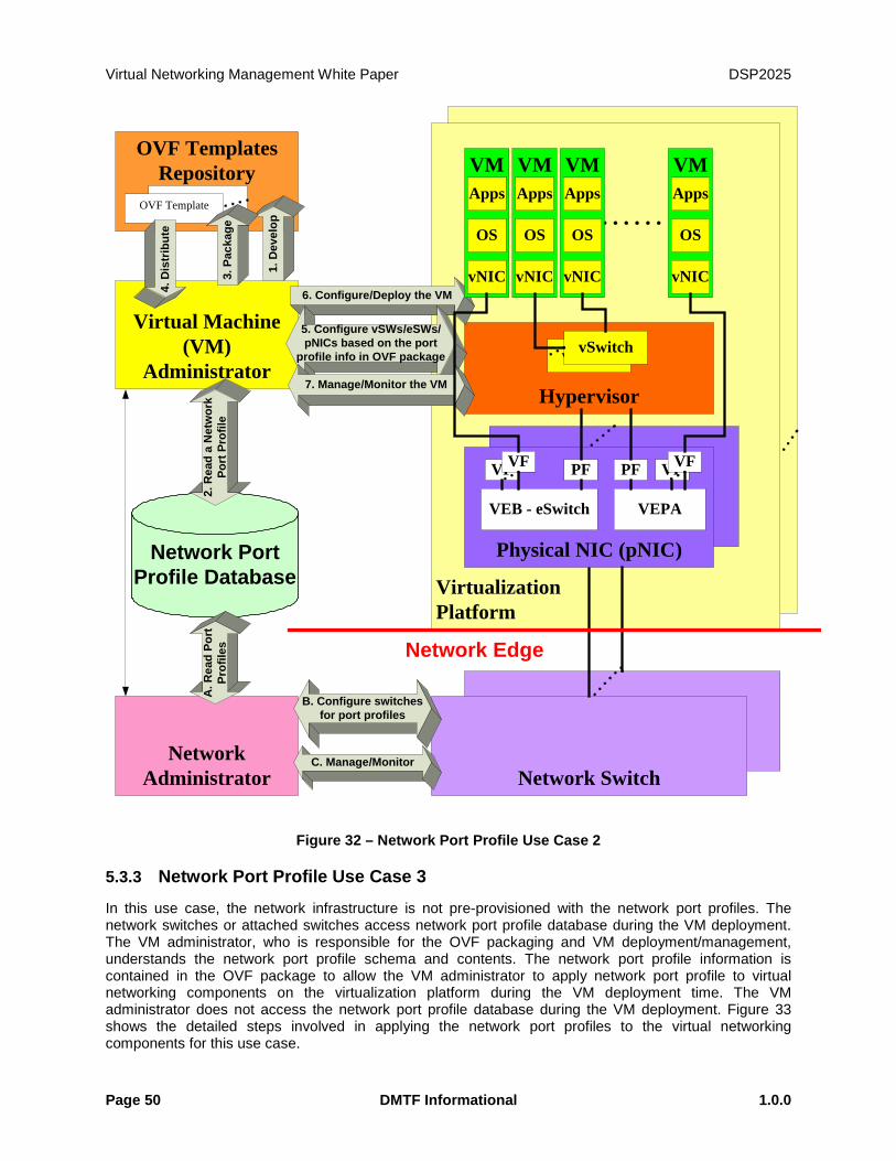
Virtual Networking Management White Paper DSP2025
Page 50 DMTF Informational 1.0.0
OVF Templates Repository
VirtualizedPlatform
Network Switch
VirtualizationPlatform
Physical NIC
Virtual Machine (VM)
AdministratorHypervisor
OVF Template
1. D
evel
op
3. P
acka
ge
4. D
istr
ibut
e
6. Configure/Deploy the VM
5. Configure vSWs/eSWs/pNICs based on the port
profile info in OVF package
VMApps
OS
Network SwitchNetwork
Administrator
vSwitch
Physical NIC (pNIC)
VEB - eSwitch VEPA
PFVFVF
vSwitch
PF VFVF
vNIC
VMApps
OS
vNIC
VMApps
OS
vNIC
VMApps
OS
vNIC
Network Port Profile Database
C. Manage/Monitor
2. R
ead
a N
etw
ork
Port
Pro
file
7. Manage/Monitor the VM
B. Configure switches for port profiles
A. R
ead
Port
Pr
ofile
s Network Edge
Figure 32 – Network Port Profile Use Case 2
5.3.3 Network Port Profile Use Case 3
In this use case, the network infrastructure is not pre-provisioned with the network port profiles. The network switches or attached switches access network port profile database during the VM deployment. The VM administrator, who is responsible for the OVF packaging and VM deployment/management, understands the network port profile schema and contents. The network port profile information is contained in the OVF package to allow the VM administrator to apply network port profile to virtual networking components on the virtualization platform during the VM deployment time. The VM administrator does not access the network port profile database during the VM deployment. Figure 33 shows the detailed steps involved in applying the network port profiles to the virtual networking components for this use case.
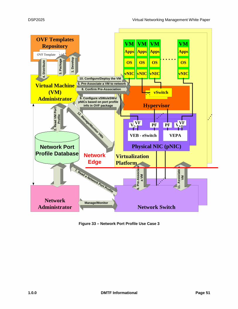
DSP2025 Virtual Networking Management White Paper
1.0.0 DMTF Informational Page 51
OVF Templates Repository
VirtualizedPlatform
Network Switch
VirtualizationPlatform
Physical NIC
Virtual Machine (VM)
AdministratorHypervisor
OVF Template
1. D
evel
op
3. P
acka
ge
4. D
istr
ibut
e
10. Configure/Deploy the VM
9. Configure vSWs/eSWs/ pNICs based on port profile
info in OVF package
VMApps
OS
Network SwitchNetwork
Administrator
vSwitch
Physical NIC (pNIC)
VEB - eSwitch VEPA
PFVFVF
vSwitch
PF VFVF
vNIC
VMApps
OS
vNIC
VMApps
OS
vNIC
VMApps
OS
vNIC
Network Port Profile Database
Manage/Monitor
2. R
ead
VM P
ort
Prof
ile
12. Manage/Monitor VMs
5. Pre-Associate a VM to network
6. P
re-A
ssoc
iate
a
VM
7. Read a Network Port Profile
8. Confirm Pre-Association
11. A
ssoc
iate
a
VM
NetworkEdge
Figure 33 – Network Port Profile Use Case 3
Virtual Networking Management White Paper DSP2025
Page 52 DMTF Informational 1.0.0
ANNEX A
(Informative) VLAN Concepts
Some basic concepts and terms involved in VLANs is explained below. The explanation and the terms used below are deemed sufficient to provide a context for the whitepaper.
A broadcast domain is a logical grouping of nodes on a computer network such that any of the nodes can reach all the other nodes by broadcasting at layer 2. Virtual LANs or VLANs are a mechanism to allow network administrators to create logical broadcast domains that can span across a single switch or multiple switches, regardless of physical proximity. This function is useful to reduce the size of broadcast domains or to allow groups or users to be logically grouped without the need to be physically located in the same place. VLANs are identified by VLAN IDs which numbers are starting 1 to 4096.
Switches are configured to have their ports carry traffic belonging to zero or more VLANs. The way the traffic between different VLANs can be distinguished is by having a special VLAN tag. Depending on the switch manufacturer the traffic between two switches may or may not always carry a VLAN tag depending on the traffic flowing between them. A switch when it is not configured may have the VLAN functionality disabled or may have it enabled with have all the ports as part of what is called the Default VLAN. Typically the VLAN ID for the default VLAN is 1. Switches may support an operation where no VLANs are defined for the ports on it. VLAN setting for switch Ports are configured statically by administrative action or dynamically via a configuration protocol that the switches execute.
Ports that send/receive traffic for multiple VLANs are called trunk ports. The traffic on links connected to such ports is tagged with a VLAN tag in for multiplexing/de-multiplexing purposes. Some vendors define what is called as a Native VLAN for a trunk port. Traffic flowing on the Native VLAN over a trunk port does not have a VLAN tag.
On Cisco switches all ports are in a single default VLAN with VLAN ID of 1. A port on a Cisco switch is either an access port or a trunk port. An access port carry’s traffic from a single VLAN, while a trunk port by default carry’s traffic from all the VLANs supported by the switch. Trunk Ports can be further configured to carry traffic from a specific set of VLANs. Configuration is carried out either statically or by switches running VLAN Trunking Protocol (VTP). To distinguish between traffic flows, a trunk port marks each from with special tags which are passed between switches. Access ports do not have special tags.
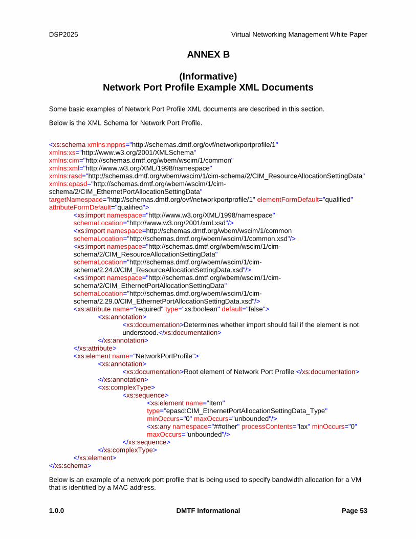
DSP2025 Virtual Networking Management White Paper
1.0.0 DMTF Informational Page 53
ANNEX B
(Informative) Network Port Profile Example XML Documents
Some basic examples of Network Port Profile XML documents are described in this section.
Below is the XML Schema for Network Port Profile.
<xs:schema xmlns:nppns="http://schemas.dmtf.org/ovf/networkportprofile/1" xmlns:xs="http://www.w3.org/2001/XMLSchema" xmlns:cim="http://schemas.dmtf.org/wbem/wscim/1/common" xmlns:xml="http://www.w3.org/XML/1998/namespace" xmlns:rasd="http://schemas.dmtf.org/wbem/wscim/1/cim-schema/2/CIM_ResourceAllocationSettingData" xmlns:epasd="http://schemas.dmtf.org/wbem/wscim/1/cim-schema/2/CIM_EthernetPortAllocationSettingData" targetNamespace="http://schemas.dmtf.org/ovf/networkportprofile/1" elementFormDefault="qualified" attributeFormDefault="qualified">
<xs:import namespace="http://www.w3.org/XML/1998/namespace" schemaLocation="http://www.w3.org/2001/xml.xsd"/> <xs:import namespace=http://schemas.dmtf.org/wbem/wscim/1/common schemaLocation="http://schemas.dmtf.org/wbem/wscim/1/common.xsd"/> <xs:import namespace="http://schemas.dmtf.org/wbem/wscim/1/cim-schema/2/CIM_ResourceAllocationSettingData" schemaLocation="http://schemas.dmtf.org/wbem/wscim/1/cim-schema/2.24.0/CIM_ResourceAllocationSettingData.xsd"/> <xs:import namespace="http://schemas.dmtf.org/wbem/wscim/1/cim-schema/2/CIM_EthernetPortAllocationSettingData" schemaLocation="http://schemas.dmtf.org/wbem/wscim/1/cim-schema/2.29.0/CIM_EthernetPortAllocationSettingData.xsd"/>
<xs:attribute name="required" type="xs:boolean" default="false"> <xs:annotation>
<xs:documentation>Determines whether import should fail if the element is not understood.</xs:documentation>
</xs:annotation> </xs:attribute> <xs:element name="NetworkPortProfile"> <xs:annotation> <xs:documentation>Root element of Network Port Profile </xs:documentation> </xs:annotation> <xs:complexType> <xs:sequence>
<xs:element name="Item" type="epasd:CIM_EthernetPortAllocationSettingData_Type" minOccurs="0" maxOccurs="unbounded"/> <xs:any namespace="##other" processContents="lax" minOccurs="0" maxOccurs="unbounded"/>
</xs:sequence> </xs:complexType> </xs:element> </xs:schema>
Below is an example of a network port profile that is being used to specify bandwidth allocation for a VM that is identified by a MAC address.

Virtual Networking Management White Paper DSP2025
Page 54 DMTF Informational 1.0.0
<?xml version="1.0" encoding="UTF-8"?>
<nppns:NetworkPortProfile xmlns:nppns="http://schemas.dmtf.org/ovf/networkportprofile/1" xmlns:xs="http://www.w3.org/2001/XMLSchema" xmlns:cim="http://schemas.dmtf.org/wbem/wscim/1/common" xmlns:xml="http://www.w3.org/XML/1998/namespace" xmlns:rasd="http://schemas.dmtf.org/wbem/wscim/1/cim-schema/2/CIM_ResourceAllocationSettingData" xmlns:epasd="http://schemas.dmtf.org/wbem/wscim/1/cim-schema/2/CIM_EthernetPortAllocationSettingData" targetNamespace="http://schemas.dmtf.org/ovf/networkportporfile/1" elementFormDefault="qualified" attributeFormDefault="qualified">
<epasd:NetworkPortProfileID>
http://www.dmtf.org/networkportporfiles
</epasd:NetworkPortProfileID>
<epasd:NetworkPortProfileIDType>2</epasd:NetworkPortProfileIDType>
<epasd:Address>00-16-8B-DB-00-5E</epasd:Address>
<rasd:AllocationUnits>GigaBits per Second</rasd:AllocationUnits>
<rasd:Reservation>1</rasd:Reservation>
</nppns:NetworkPortProfile>
The example below shows a list of allowed MAC Address/VLAN pairs on a network port.
<?xml version="1.0" encoding="UTF-8"?>
<nppns:NetworkPortProfile xmlns:nppns="http://schemas.dmtf.org/ovf/networkportprofile/1" xmlns:xs="http://www.w3.org/2001/XMLSchema" xmlns:cim="http://schemas.dmtf.org/wbem/wscim/1/common" xmlns:xml="http://www.w3.org/XML/1998/namespace" xmlns:rasd="http://schemas.dmtf.org/wbem/wscim/1/cim-schema/2/CIM_ResourceAllocationSettingData" xmlns:epasd="http://schemas.dmtf.org/wbem/wscim/1/cim-schema/2/CIM_EthernetPortAllocationSettingData" targetNamespace="http://schemas.dmtf.org/ovf/networkportporfile/1" elementFormDefault="qualified" attributeFormDefault="qualified">
<epasd:NetworkPortProfileID>
http://www.dmtf.org/networkportporfiles
</epasd:NetworkPortProfileID>
<epasd:NetworkPortProfileIDType>2</epasd:NetworkPortProfileIDType>
<epasd:AllowedToTransmitMACAddresses>
00-16-8B-DB-00-5E
</epasd:AllowedToTransmitMACAddresses>
<epasd:AllowedToTransmitMACAddresses>
00-17-8B-DA-00-5E
</epasd:AllowedToTransmitMACAddresses>
<epasd:AllowedToTransmitVLANs>
5
</epasd:AllowedToTransmitVLANs>
<epasd:AllowedToTransmitVLANs>
7
</epasd:AllowedToTransmitVLANs>
</nppns:NetworkPortProfile>
A network port profile can be used to represent allowed source MAC addresses in the transmit direction as shown in the example below.
<?xml version="1.0" encoding="UTF-8"?>
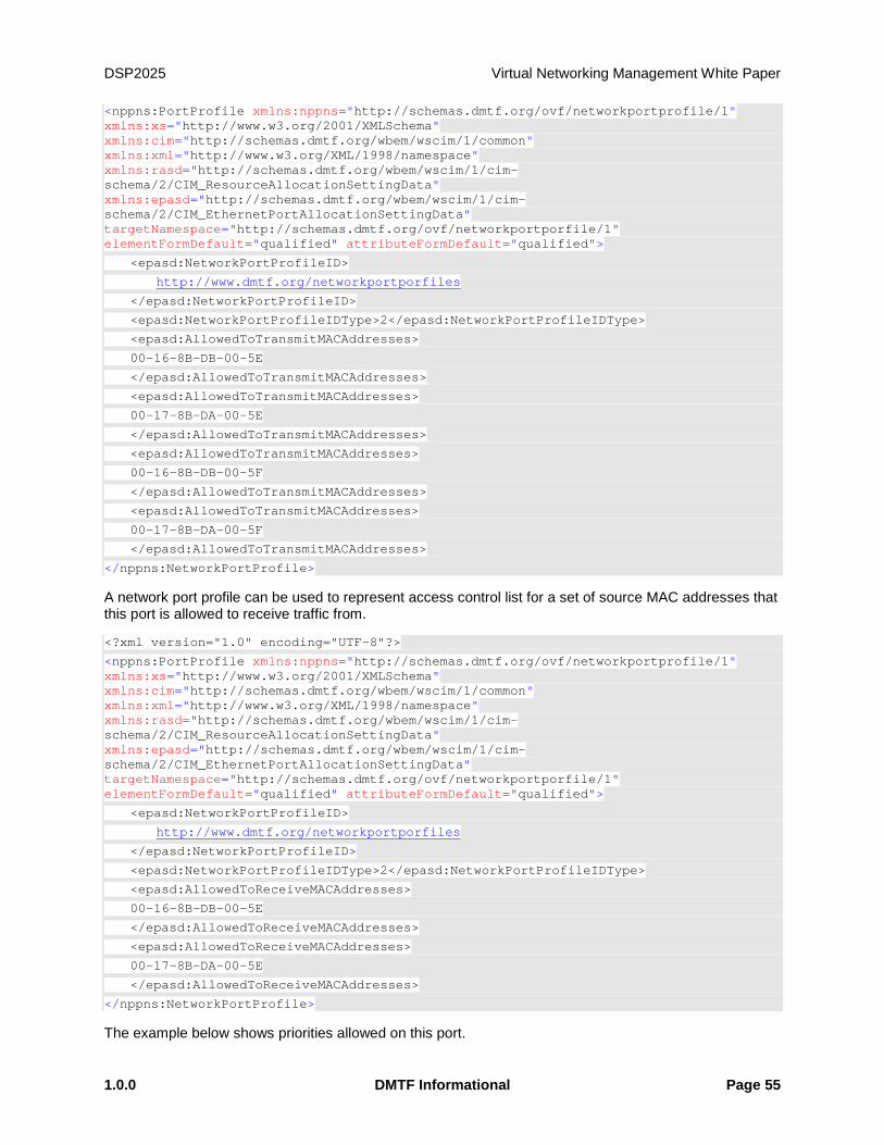
DSP2025 Virtual Networking Management White Paper
1.0.0 DMTF Informational Page 55
<nppns:PortProfile xmlns:nppns="http://schemas.dmtf.org/ovf/networkportprofile/1" xmlns:xs="http://www.w3.org/2001/XMLSchema" xmlns:cim="http://schemas.dmtf.org/wbem/wscim/1/common" xmlns:xml="http://www.w3.org/XML/1998/namespace" xmlns:rasd="http://schemas.dmtf.org/wbem/wscim/1/cim-schema/2/CIM_ResourceAllocationSettingData" xmlns:epasd="http://schemas.dmtf.org/wbem/wscim/1/cim-schema/2/CIM_EthernetPortAllocationSettingData" targetNamespace="http://schemas.dmtf.org/ovf/networkportporfile/1" elementFormDefault="qualified" attributeFormDefault="qualified">
<epasd:NetworkPortProfileID>
http://www.dmtf.org/networkportporfiles
</epasd:NetworkPortProfileID>
<epasd:NetworkPortProfileIDType>2</epasd:NetworkPortProfileIDType>
<epasd:AllowedToTransmitMACAddresses>
00-16-8B-DB-00-5E
</epasd:AllowedToTransmitMACAddresses>
<epasd:AllowedToTransmitMACAddresses>
00-17-8B-DA-00-5E
</epasd:AllowedToTransmitMACAddresses>
<epasd:AllowedToTransmitMACAddresses>
00-16-8B-DB-00-5F
</epasd:AllowedToTransmitMACAddresses>
<epasd:AllowedToTransmitMACAddresses>
00-17-8B-DA-00-5F
</epasd:AllowedToTransmitMACAddresses>
</nppns:NetworkPortProfile>
A network port profile can be used to represent access control list for a set of source MAC addresses that this port is allowed to receive traffic from.
<?xml version="1.0" encoding="UTF-8"?>
<nppns:PortProfile xmlns:nppns="http://schemas.dmtf.org/ovf/networkportprofile/1" xmlns:xs="http://www.w3.org/2001/XMLSchema" xmlns:cim="http://schemas.dmtf.org/wbem/wscim/1/common" xmlns:xml="http://www.w3.org/XML/1998/namespace" xmlns:rasd="http://schemas.dmtf.org/wbem/wscim/1/cim-schema/2/CIM_ResourceAllocationSettingData" xmlns:epasd="http://schemas.dmtf.org/wbem/wscim/1/cim-schema/2/CIM_EthernetPortAllocationSettingData" targetNamespace="http://schemas.dmtf.org/ovf/networkportporfile/1" elementFormDefault="qualified" attributeFormDefault="qualified">
<epasd:NetworkPortProfileID>
http://www.dmtf.org/networkportporfiles
</epasd:NetworkPortProfileID>
<epasd:NetworkPortProfileIDType>2</epasd:NetworkPortProfileIDType>
<epasd:AllowedToReceiveMACAddresses>
00-16-8B-DB-00-5E
</epasd:AllowedToReceiveMACAddresses>
<epasd:AllowedToReceiveMACAddresses>
00-17-8B-DA-00-5E
</epasd:AllowedToReceiveMACAddresses>
</nppns:NetworkPortProfile>
The example below shows priorities allowed on this port.
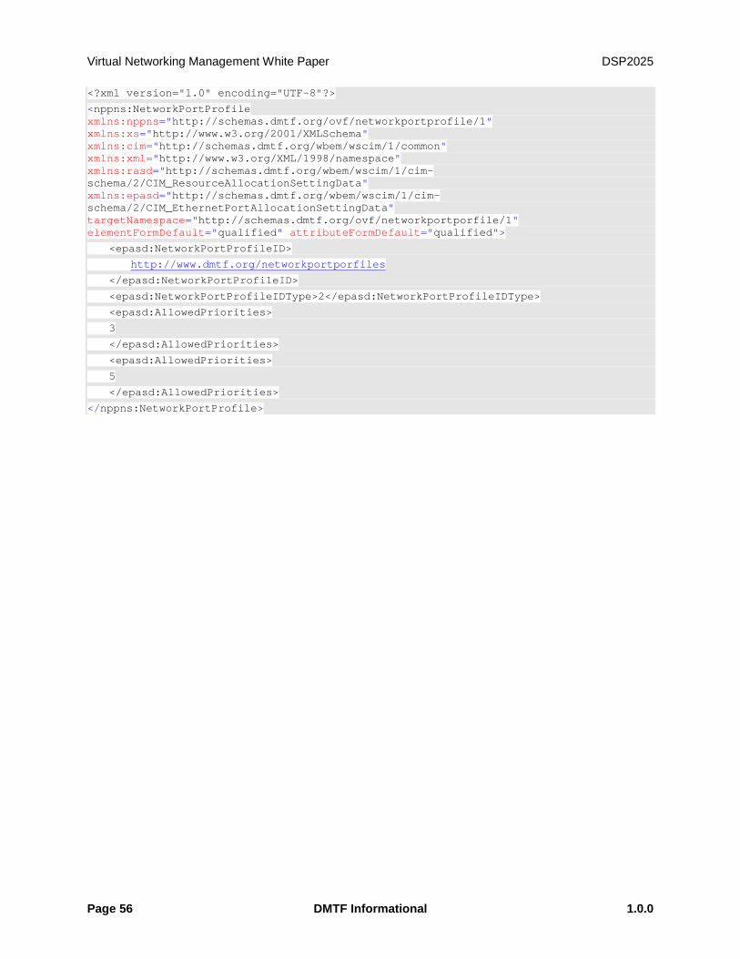
Virtual Networking Management White Paper DSP2025
Page 56 DMTF Informational 1.0.0
<?xml version="1.0" encoding="UTF-8"?>
<nppns:NetworkPortProfile xmlns:nppns="http://schemas.dmtf.org/ovf/networkportprofile/1" xmlns:xs="http://www.w3.org/2001/XMLSchema" xmlns:cim="http://schemas.dmtf.org/wbem/wscim/1/common" xmlns:xml="http://www.w3.org/XML/1998/namespace" xmlns:rasd="http://schemas.dmtf.org/wbem/wscim/1/cim-schema/2/CIM_ResourceAllocationSettingData" xmlns:epasd="http://schemas.dmtf.org/wbem/wscim/1/cim-schema/2/CIM_EthernetPortAllocationSettingData" targetNamespace="http://schemas.dmtf.org/ovf/networkportporfile/1" elementFormDefault="qualified" attributeFormDefault="qualified">
<epasd:NetworkPortProfileID>
http://www.dmtf.org/networkportporfiles
</epasd:NetworkPortProfileID>
<epasd:NetworkPortProfileIDType>2</epasd:NetworkPortProfileIDType>
<epasd:AllowedPriorities>
3
</epasd:AllowedPriorities>
<epasd:AllowedPriorities>
5
</epasd:AllowedPriorities>
</nppns:NetworkPortProfile>
DSP2025 Virtual Networking Management White Paper
1.0.0 DMTF Informational Page 57
ANNEX C (informative)
Change log
Version Date Description
DMTF 1.0.0 2012-02-14 DMTF Whtie Paper first release