Embed Size (px)
Citation preview
Implementation Guide
1
Virtual Chassis Technology Best Practices
2
Implementation GuideVirtual Chassis Technology Best Practices
©2015, Juniper Networks, Inc.
Table of ContentsIntroduction ....................................................................................................................................................................................................................... 4
Scope .................................................................................................................................................................................................................................... 5
Virtual Chassis Technology Concepts...................................................................................................................................................................... 5
Virtual Chassis Ports .............................................................................................................................................................................................. 5
Extended Virtual Chassis Ports ........................................................................................................................................................................... 5
Virtual Chassis Port LAG ........................................................................................................................................................................................6
Local Link Bias ....................................................................................................................................................................................................6
Mixed Virtual Chassis ..............................................................................................................................................................................................6
Virtual Chassis Member Roles .............................................................................................................................................................................6
Master Role ...........................................................................................................................................................................................................7
Backup Role ..........................................................................................................................................................................................................7
Line Card Role ......................................................................................................................................................................................................7
Mastership Priority Setting .............................................................................................................................................................................8
Non-Provisioned Method ...............................................................................................................................................................................8
Member ID Numbering ...................................................................................................................................................................................9
Preprovisioned Method ................................................................................................................................................................................. 10
Graceful Routing Engine Switchover ............................................................................................................................................................... 10
Nonstop Active Routing ....................................................................................................................................................................................... 10
Nonstop Bridging ......................................................................................................................................................................................................11
Forwarding Path .......................................................................................................................................................................................................11
Virtual Chassis Control Protocol .........................................................................................................................................................................11
Fast Failover ...............................................................................................................................................................................................................11
Software Compatibility .........................................................................................................................................................................................11
Automatic Software Update........................................................................................................................................................................12
Nonstop Software Upgrade .........................................................................................................................................................................12
Feature Licenses in Virtual Chassis ..................................................................................................................................................................12
Design Considerations ..................................................................................................................................................................................................12
How Many Members Should a Virtual Chassis Configuration Have? ................................................................................................12
Option 1: ...............................................................................................................................................................................................................13
Option 2: ...............................................................................................................................................................................................................13
Location of Master and Backup Switches .....................................................................................................................................................13
Virtual Chassis Topologies ...................................................................................................................................................................................14
Cabling Options ......................................................................................................................................................................................................15
Daisy-Chained Ring .........................................................................................................................................................................................15
Braided-Ring Cabling ..................................................................................................................................................................................... 16
Extended Virtual Chassis Configuration ................................................................................................................................................. 16
Virtual Chassis Cabling using SFP+ or QSFP+ Ports ......................................................................................................................... 16
Using Uplinks ............................................................................................................................................................................................................. 17
Class of Service (CoS) on VCP ........................................................................................................................................................................... 17
Virtual Chassis Split ................................................................................................................................................................................................ 17
Virtual Chassis Merge ............................................................................................................................................................................................ 18
Implementation .............................................................................................................................................................................................................. 19
Non-Provisioned Mode Installation ................................................................................................................................................................. 19
Using the LCD Menus on a Switch ............................................................................................................................................................ 19
Preprovisioned Mode Installation .................................................................................................................................................................... 20
Managing and Maintaining a Virtual Chassis Configuration ...................................................................................................................21
Adding a New Switch to an Existing Virtual Chassis Configuration in the Same Wiring Closet ........................................21
Replacing a Member Switch ........................................................................................................................................................................21
3
Implementation GuideVirtual Chassis Technology Best Practices
©2015, Juniper Networks, Inc.
Virtual Chassis Management .............................................................................................................................................................................22
Synchronizing Virtual Chassis Members ........................................................................................................................................................23
Loading Factory Default Settings .....................................................................................................................................................................23
Virtual Chassis Failover................................................................................................................................................................................................23
Monitoring a Virtual Chassis Configuration .........................................................................................................................................................23
Monitoring Operation with CLI Commands .................................................................................................................................................23
Monitoring with SNMP ..........................................................................................................................................................................................24
jnxVirtualChassisMemberTable .................................................................................................................................................................24
jnxVirtualChassisPortTable ..........................................................................................................................................................................24
Virtual Chassis Technology Deployment Options.............................................................................................................................................24
Data Center, Top-of-Rack Deployment .........................................................................................................................................................24
Data Center, End-of-Row Deployment ..........................................................................................................................................................24
Campus or Building Wiring Closet Deployment .........................................................................................................................................24
Campus or Building Aggregation Deployment ............................................................................................................................................25
Virtual Chassis Ring Deployment .....................................................................................................................................................................26
Best Practices..................................................................................................................................................................................................................26
Conclusion ........................................................................................................................................................................................................................ 27
Appendix A: Virtual Chassis Ports on EX Series Switches ............................................................................................................................. 27
Appendix B: Mixed Virtual Chassis Support ........................................................................................................................................................ 27
Appendix C: Glossary .................................................................................................................................................................................................. 28
About Juniper Networks ..............................................................................................................................................................................................29
List of FiguresFigure 1: Virtual Chassis configuration ..................................................................................................................................................................... 5
Figure 2: Virtual Chassis ports on an EX4200 switch rear panel .................................................................................................................. 5
Figure 3: Member roles in a Virtual Chassis configuration ................................................................................................................................7
Figure 4: Member ID assignments .............................................................................................................................................................................9
Figure 5: Recommended member location in a daisy-chained ring deployment .................................................................................13
Figure 6: Recommended member location in a braided-ring deployment .............................................................................................13
Figure 7: Recommended member location in a physically distributed deployment ............................................................................13
Figure 8: Single ring topology .....................................................................................................................................................................................14
Figure 9: Full mesh topology ......................................................................................................................................................................................14
Figure 10: Multiple rings topology .............................................................................................................................................................................15
Figure 11: Dedicated Virtual Chassis daisy-chained ring ..................................................................................................................................15
Figure 12: Dedicated Virtual Chassis braided-ring cabling ............................................................................................................................. 16
Figure 13: Extended Virtual Chassis configuration ............................................................................................................................................ 16
Figure 14: Uplinks in a Virtual Chassis configuration ......................................................................................................................................... 17
Figure 15: Campus or building wiring closet deployment, single wiring closet ......................................................................................25
Figure 16: Campus or building wiring closet deployment, multiple wiring closets ...............................................................................25
Figure 17: Campus aggregation, single Virtual Chassis configuration ........................................................................................................26
4
Implementation GuideVirtual Chassis Technology Best Practices
©2015, Juniper Networks, Inc.
Introduction Juniper Networks Virtual Chassis technology is a feature of select Juniper Networks® EX Series and QFX Series Ethernet
Switches, allowing the interconnection and operation of multiple switches as a unified, single, high-bandwidth device.
Depending on the model, up to 10 switches may be interconnected through ports that are configured as Virtual Chassis
ports.
Virtual Chassis technology is supported on the following platforms. Please refer to Juniper technical documentation for
the latest support information.
• EX2200 Ethernet Switch
• EX3300 Ethernet Switch
• EX4200 Ethernet Switch
• EX4300 Ethernet Switch
• EX4550 Ethernet Switch
• EX4600 Ethernet Switch
• QFX3500 Switch
• QFX3600 Switch
• QFX5100 Switch
Solutions that use Virtual Chassis technology combine the scalability and compact form factor of standalone switches
with the high availability, high backplane bandwidth characteristics and high port densities of traditional chassis-based
switches. Virtual Chassis configurations enable economical deployments of switches that deliver network availability in
locations where installation might otherwise be cost prohibitive or physically impossible.
In a Virtual Chassis configuration, all member switches are managed and monitored as a single logical device. This
approach simplifies network operations, allows the separation of placement and logical groupings of physical devices,
and provides efficient use of resources. The Virtual Chassis solution offers the same Routing Engine (RE) redundancy
features as other Juniper Networks chassis-based switches and routers, including graceful Routing Engine switchover
(GRES) for hitless failover.
For resiliency and redundancy, Virtual Chassis configurations include a master and a backup switch, both dynamically
elected as part of the Virtual Chassis deployment process. Each remaining switch serves as a line card, but is ready to be
selected as a backup switch if the master or backup switch fails. Switches may also be selectively prioritized in a Virtual
Chassis configuration to assign master and backup roles, and to determine the order in which the remaining switches are
elected if the master and backup switches fail.
Virtual Chassis configuration management is performed through the master switch. A Virtual Management Ethernet
(VME) interface allows remote management by connecting to the out-of-band management port of any member
switch through a single IP address.
In addition, the Virtual Chassis configuration uses a single Juniper Networks Junos® operating system image file and
a single configuration file. The Junos OS of all member switches in a Virtual Chassis configuration can be upgraded
simultaneously from the master switch with a single command.
Key benefits of Virtual Chassis technology include:
• Simplified overall system maintenance and management through a single management interface
• Pay-as-you-grow scalability, from 24 to 480 10/100/1000 Mbps ports
• Extension of the Virtual Chassis configuration by several kilometers
• Consistent modular Junos OS control plane feature implementation
• Dual REs with GRES
5
Implementation GuideVirtual Chassis Technology Best Practices
©2015, Juniper Networks, Inc.
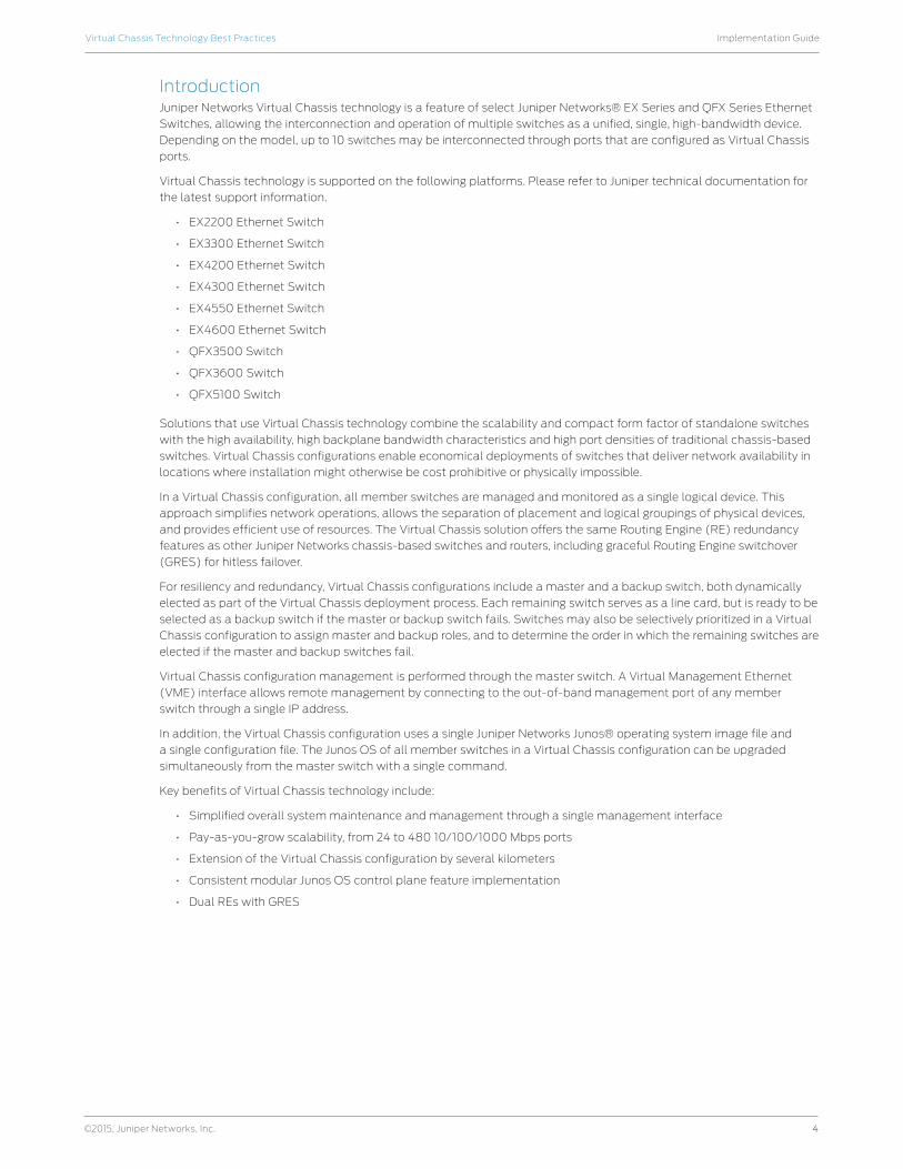
Figure 1 illustrates a typical Virtual Chassis configuration using five EX4300 switches.
Figure 1: Virtual Chassis configuration
ScopeThis best practices implementation guide provides information about Juniper’s Ethernet switches with Virtual Chassis
technology. It describes this technology, explains key concepts, and provides information about designing, operating,
maintaining, and managing a Virtual Chassis configuration. This document does not attempt to capture all configuration
options and features specific to platforms. Please refer to product-specific documentation for detailed feature support.
This document primarily focuses on Virtual Chassis support in EX Series switches. It is intended for system engineers,
system administrators, and others who have the technical background required to understand, position, and/or deploy
Virtual Chassis technology. For platform-specific information that is the focus of this guide, please refer to the Appendix.
For up-to-date support information, refer to Juniper documentation.
Virtual Chassis Technology ConceptsThe following sections provide an overview of Virtual Chassis technology concepts.
Virtual Chassis Ports A Virtual Chassis configuration consists of between 2 and 10 switches connected together through Virtual Chassis ports
(VCPs). Configurations can range from a deployment in which each switch is physically colocated, to a deployment in
which switches are separated by several kilometers. Each switch within a Virtual Chassis configuration is a member of
that Virtual Chassis.
Legacy platforms like EX4200 and EX4550 use dedicated Virtual Chassis ports, which will be used as the primary VCPs.
You will need a Juniper Virtual Chassis cable to connect these dedicated VCPs. These platforms also provide the ability
to configure one of the small form-factor pluggable transceiver or SFP plus transceiver (SFP/SFP+) ports as extended
Virtual Chassis ports, enabling Virtual Chassis deployments to extend across several kilometers where necessary.
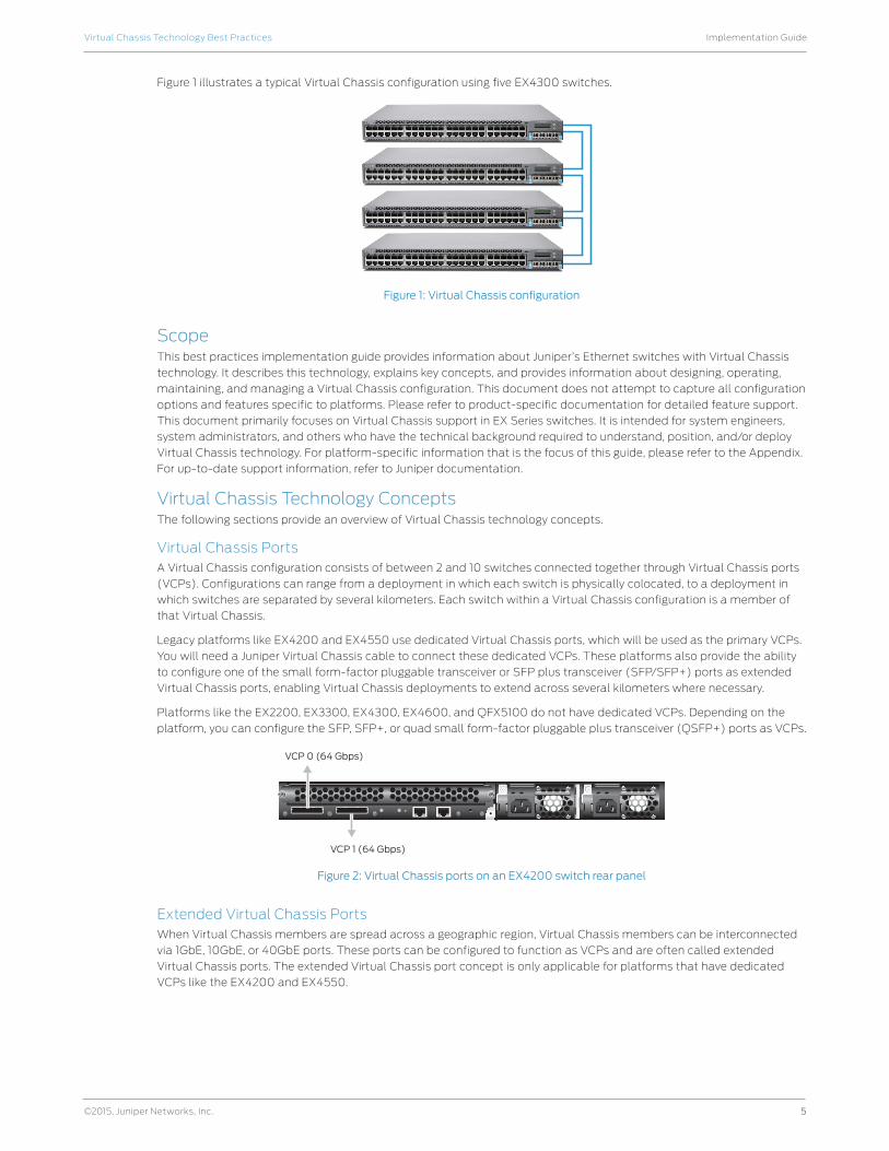
Platforms like the EX2200, EX3300, EX4300, EX4600, and QFX5100 do not have dedicated VCPs. Depending on the
platform, you can configure the SFP, SFP+, or quad small form-factor pluggable plus transceiver (QSFP+) ports as VCPs.
VCP 0 (64 Gbps)
VCP 1 (64 Gbps)
Figure 2: Virtual Chassis ports on an EX4200 switch rear panel
Extended Virtual Chassis PortsWhen Virtual Chassis members are spread across a geographic region, Virtual Chassis members can be interconnected
via 1GbE, 10GbE, or 40GbE ports. These ports can be configured to function as VCPs and are often called extended
Virtual Chassis ports. The extended Virtual Chassis port concept is only applicable for platforms that have dedicated
VCPs like the EX4200 and EX4550.
6
Implementation GuideVirtual Chassis Technology Best Practices
©2015, Juniper Networks, Inc.
Virtual Chassis Port LAGYou can combine physical Ethernet ports belonging to different member switches of a Virtual Chassis configuration to
form a logical point-to-point link, known as a link aggregation group (LAG) or bundle. A LAG provides more bandwidth
than a single Ethernet link can provide. Additionally, link aggregation provides network redundancy by load-balancing
traffic across all available links. If one of the links fails, the system automatically load-balances traffic across all
remaining links.
When two switches are interconnected using multiple VCPs, the ports form a LAG bundle automatically. This enables
effective bandwidth utilization on the backplane and also provides link-level redundancy for VCPs. On dual-PFE
systems, if the VCPs are on different PFEs, they will not form a LAG.
Local Link Bias
When local link bias is disabled, egress traffic exiting a Virtual Chassis on a LAG bundle can be forwarded out of any
member link in the LAG bundle. Traffic forwarding decisions are made by an internal algorithm that attempts to load-
balance traffic between the member links in the bundle. VCP bandwidth is frequently consumed by egress traffic when
local link bias is disabled because the egress traffic traverses the VCPs to reach the destination egress member link in
the LAG bundle.
Local link bias conserves bandwidth on VCPs by using local links to forward unicast traffic exiting a Virtual Chassis that
has a LAG bundle composed of member links on different member switches in the same Virtual Chassis configuration.
A local link is a member link in the LAG bundle that is on the member switch that received the traffic. Because traffic is
received and forwarded on the same member switch when local link bias is enabled, no VCP bandwidth is consumed by
traffic traversing the VCPs to exit the Virtual Chassis using a different member link in the LAG bundle.
Local link bias only impacts the forwarding of unicast traffic exiting a Virtual Chassis configuration. Ingress traffic
handling is not impacted by the local link bias setting. Egress multicast, unknown unicast, and broadcast traffic exiting a
Virtual Chassis configuration over a LAG bundle are also not impacted by the local link bias setting and are always load-
balanced among the member links. Local link bias is disabled by default.
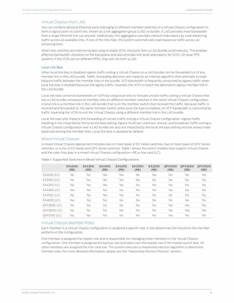
Mixed Virtual ChassisA mixed Virtual Chassis deployment includes two or more types of EX Series switches, two or more types of QFX Series
switches, or a mix of EX Series and QFX Series switches. Table 1 shows the switch models that support Virtual Chassis
and the roles they play in a mixed Virtual Chassis configuration—RE or line card (LC).
Table 1: Supported Switches in Mixed Virtual Chassis Configurations
EX4600 (RE)
EX4300 (RE)
EX4550 (RE)
EX4200 (RE)
EX3300 (RE)
EX2200 (RE)
QFX5100 (RE)
QFX3600 (RE)
QFX3500 (RE)
EX2200 (LC) No No Yes Yes No Yes No No No
EX3300 (LC) No No Yes Yes Yes No No No No
EX4200 (LC) No No Yes Yes No No No No No
EX4300 (LC) Yes Yes No No No No Yes No No
EX4550 (LC) No No Yes No No No No No No
EX4600 (LC) Yes No No No No No No No No
QFX3500 (LC) No No No No No No Yes Yes Yes
QFX3600 (LC) No No No No No No Yes Yes Yes
QFX5100 (LC) No No No No No No Yes No No
Virtual Chassis Member RolesEach member in a Virtual Chassis configuration is assigned a specific role. A role determines the functions the member
performs in the configuration.
One member is assigned the master role and is responsible for managing other members in the Virtual Chassis
configuration. One member is assigned the backup role and takes over the master role if the master switch fails. All
other members are assigned the line-card role. The system executes a mastership election algorithm to determine
member roles. For more detailed information, please see the “Mastership Election Process” section.
7
Implementation GuideVirtual Chassis Technology Best Practices
©2015, Juniper Networks, Inc.
0 1 2 3 4 5 6 7 8 9 10 11 12 13 14 15 16 17 18 19 20 21 22 23 24 25 26 27 28 29 30 31 32 33 34 35 36 37 38 39 40 41 42 43 44 45 46 47
48PoEEX 4200 Series
0 1 2 3 4 5 6 7 8 9 10 11 12 13 14 15 16 17 18 19 20 21 22 23 24 25 26 27 28 29 30 31 32 33 34 35 36 37 38 39 40 41 42 43 44 45 46 47
48PoEEX 4200 Series
Switch elected as Backup viaElection Decision Tree
0 1 2 3 4 5 6 7 8 9 10 11 12 13 14 15 16 17 18 19 20 21 22 23 24 25 26 27 28 29 30 31 32 33 34 35 36 37 38 39 40 41 42 43 44 45 46 47
48PoEEX 4200 Series
0 1 2 3 4 5 6 7 8 9 10 11 12 13 14 15 16 17 18 19 20 21 22 23 24 25 26 27 28 29 30 31 32 33 34 35 36 37 38 39 40 41 42 43 44 45 46 47
48PoEEX 4200 Series
Line Card (LC)
Backup (RE1)
Switch elected as Master viaElection Decision Tree
Master (RE0)
Line Card (LC)
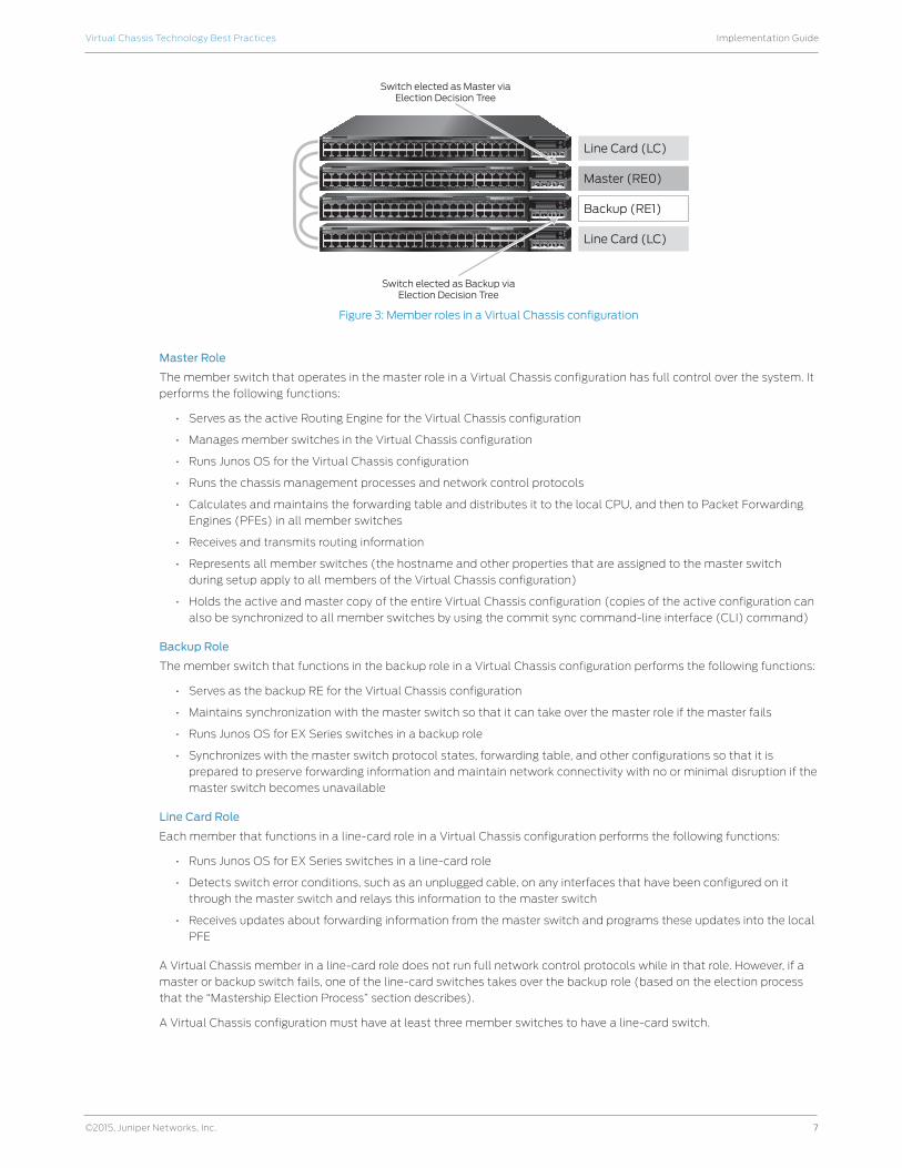
Figure 3: Member roles in a Virtual Chassis configuration
Master Role
The member switch that operates in the master role in a Virtual Chassis configuration has full control over the system. It
performs the following functions:
• Serves as the active Routing Engine for the Virtual Chassis configuration
• Manages member switches in the Virtual Chassis configuration
• Runs Junos OS for the Virtual Chassis configuration
• Runs the chassis management processes and network control protocols
• Calculates and maintains the forwarding table and distributes it to the local CPU, and then to Packet Forwarding
Engines (PFEs) in all member switches
• Receives and transmits routing information
• Represents all member switches (the hostname and other properties that are assigned to the master switch
during setup apply to all members of the Virtual Chassis configuration)
• Holds the active and master copy of the entire Virtual Chassis configuration (copies of the active configuration can
also be synchronized to all member switches by using the commit sync command-line interface (CLI) command)
Backup Role
The member switch that functions in the backup role in a Virtual Chassis configuration performs the following functions:
• Serves as the backup RE for the Virtual Chassis configuration
• Maintains synchronization with the master switch so that it can take over the master role if the master fails
• Runs Junos OS for EX Series switches in a backup role
• Synchronizes with the master switch protocol states, forwarding table, and other configurations so that it is
prepared to preserve forwarding information and maintain network connectivity with no or minimal disruption if the
master switch becomes unavailable
Line Card Role
Each member that functions in a line-card role in a Virtual Chassis configuration performs the following functions:
• Runs Junos OS for EX Series switches in a line-card role
• Detects switch error conditions, such as an unplugged cable, on any interfaces that have been configured on it
through the master switch and relays this information to the master switch
• Receives updates about forwarding information from the master switch and programs these updates into the local
PFE
A Virtual Chassis member in a line-card role does not run full network control protocols while in that role. However, if a
master or backup switch fails, one of the line-card switches takes over the backup role (based on the election process
that the “Mastership Election Process” section describes).
A Virtual Chassis configuration must have at least three member switches to have a line-card switch.
8
Implementation GuideVirtual Chassis Technology Best Practices
©2015, Juniper Networks, Inc.
Mastership Priority Setting
The role (master, backup, or line card) that a member switch performs within the Virtual Chassis configuration can be
determined by configuring its mastership priority from 1 to 255. (For information about a preprovisioned configuration,
please see the “Preprovisioned Method” section.) By default, switches have the default mastership priority value of 128.
The role of the switches in the Virtual Chassis can be determined either using the non-provisioned method or the
preprovisioned method.
• Non-provisioned method: The master sequentially assigns a member ID to other member switches. The role is
determined by the mastership priority value and other factors in the master election algorithm.
• Preprovisioned method: Deterministically control the member ID and role assigned to a member switch by tying
the member switch to its serial number.
Note: Wherever possible, we recommend using the preprovisioned method for adding member switches to the Virtual
Chassis configuration.
Non-Provisioned Method
Mastership Election Process
When a Virtual Chassis configuration boots, the Junos OS automatically runs the mastership election process to
determine which member switches take the role of master, backup, and line cards. All Virtual Chassis member switches
participate in the election process. If a master switch fails, the backup switch automatically and immediately takes
on the master role, which minimizes interruption to the operation of the Virtual Chassis configuration. The system
subsequently runs the mastership election process to elect one of the line-card switches as the new backup switch.
(The system also runs this process if the backup switch fails.)
The election algorithm follows the sequence below to assign member roles and elect a master and a backup switch.
The master role is assigned to the switch with the highest ranking. The backup role is assigned to the switch with the
second highest ranking. Other switches become line cards.
1. Choose the member with the highest user-configured mastership priority. (One is the lowest and 255 is the highest
possible value; please see the “Mastership Priority Setting” section for more information.)
2. Choose the member that was the master switch the last time the Virtual Chassis configuration booted.
3. In a Virtual Chassis configuration merge scenario, choose the master member that has the highest number of
current members in the existing Virtual Chassis configuration. (A merge scenario occurs when two active Virtual
Chassis configurations, each with its own master, are combined.)
4. Choose the member that has been included in the Virtual Chassis configuration the longest. (For this factor to be
considered, there must be a lapse of at least one minute between the power-on of each interconnected member
switch.)
5. Choose the member with the lowest media access control (MAC) address.
If you want to ensure that a specific member is elected as the master switch during initial Virtual Chassis installation,
follow these steps:
1. Power on only the switch you want to configure as master of the Virtual Chassis configuration.
2. Configure the mastership priority of that switch to have the highest possible value (255).
3. Without connecting to the master switch, power on all other member switches individually and reset their
configurations to factory-default values either through the front LCD menu or by using the following configuration
mode CLI command:
user@host# load factory-default
4. Connect all other members to the master switch while they are powered off.
5. Power on the other member switches.
6. Configure other member switches through the master switch, as desired. These member switches default to a
mastership priority of 128 if no previous configuration exists.
Note: We recommend the following guidelines for assigning mastership priority in a non-provisioned Virtual Chassis
configuration:
• Specify the same mastership priority value for the master and backup switches in a Virtual Chassis configuration.
Doing so helps ensure a smooth transition from master to backup if the master switch becomes unavailable. This
configuration also prevents the original master switch from retaking control from the backup switch when the
original master switch comes back online, a situation sometimes referred to as flapping or preemption, which
reduces the efficiency of system operation.
9
Implementation GuideVirtual Chassis Technology Best Practices
©2015, Juniper Networks, Inc.
• Configure the highest possible mastership priority value (255) for the master and backup switches. This
configuration ensures that these members continue to function as the master and backup even when new
members are added to the Virtual Chassis configuration.
Member ID Numbering
Each switch is a potential member of a Virtual Chassis configuration. When a switch powers on, it receives a member
ID (which is displayed on its front-panel LCD). If the switch powers on as a standalone switch, its member ID is 0. When
the switch interconnects with other switches in a Virtual Chassis configuration, the master switch assigns a member
ID (0 through 9) to the switch. The member ID is based on a variety of factors, including the order in which the switch
was added to the Virtual Chassis configuration. As each switch is added and powered on, it receives the next available
(unused) member ID.
The member ID distinguishes member switches from one another and is used to:
• Assign a mastership priority value to a member switch.
• Configure interfaces for a member switch (a function that is similar to a slot number on Juniper’s chassis-based
routers and switches).
• Apply various operational commands to a member switch.
• Display status or characteristics of a member switch.
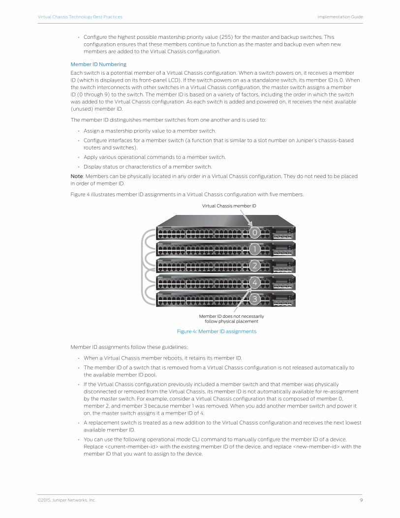
Note: Members can be physically located in any order in a Virtual Chassis configuration. They do not need to be placed
in order of member ID.
Figure 4 illustrates member ID assignments in a Virtual Chassis configuration with five members.
0 1 2 3 4 5 6 7 8 9 10 11 12 13 14 15 16 17 18 19 20 21 22 23 24 25 26 27 28 29 30 31 32 33 34 35 36 37 38 39 40 41 42 43 44 45 46 47
48PoEEX 4200 Series
0 1 2 3 4 5 6 7 8 9 10 11 12 13 14 15 16 17 18 19 20 21 22 23 24 25 26 27 28 29 30 31 32 33 34 35 36 37 38 39 40 41 42 43 44 45 46 47
48PoEEX 4200 Series
Member ID does not necessarilyfollow physical placement
Virtual Chassis member ID
0 1 2 3 4 5 6 7 8 9 10 11 12 13 14 15 16 17 18 19 20 21 22 23 24 25 26 27 28 29 30 31 32 33 34 35 36 37 38 39 40 41 42 43 44 45 46 47
48PoEEX 4200 Series
0 1 2 3 4 5 6 7 8 9 10 11 12 13 14 15 16 17 18 19 20 21 22 23 24 25 26 27 28 29 30 31 32 33 34 35 36 37 38 39 40 41 42 43 44 45 46 47
48PoEEX 4200 Series
0 1 2 3 4 5 6 7 8 9 10 11 12 13 14 15 16 17 18 19 20 21 22 23 24 25 26 27 28 29 30 31 32 33 34 35 36 37 38 39 40 41 42 43 44 45 46 47
48PoEEX 4200 Series
0
1
2
4
3
Figure 4: Member ID assignments
Member ID assignments follow these guidelines:
• When a Virtual Chassis member reboots, it retains its member ID.
• The member ID of a switch that is removed from a Virtual Chassis configuration is not released automatically to
the available member ID pool.
• If the Virtual Chassis configuration previously included a member switch and that member was physically
disconnected or removed from the Virtual Chassis, its member ID is not automatically available for re-assignment
by the master switch. For example, consider a Virtual Chassis configuration that is composed of member 0,
member 2, and member 3 because member 1 was removed. When you add another member switch and power it
on, the master switch assigns it a member ID of 4.
• A replacement switch is treated as a new addition to the Virtual Chassis configuration and receives the next lowest
available member ID.
• You can use the following operational mode CLI command to manually configure the member ID of a device.
Replace <current-member-id> with the existing member ID of the device, and replace <new-member-id> with the
member ID that you want to assign to the device.
10
Implementation GuideVirtual Chassis Technology Best Practices
©2015, Juniper Networks, Inc.
user@host> request virtual-chassis renumber member-id <current-member-id>
new-member-id <new-member-id>
• You can use the following CLI command to return a member ID that was previously used but is no longer assigned
to any active member to the member ID pool. Replace <current-member-id> with the desired member ID.
user@host> request virtual-chassis recycle member-id <current-member-id>
Preprovisioned Method
A preprovisioned configuration allows you to deterministically control the member ID and role assigned to a member
switch by associating the switch with its serial number. A preprovisioned configuration file links the serial number of each
switch to a designated member ID and role. The serial number must be specified in the configuration file for the member
to be recognized as part of the Virtual Chassis configuration.
In this configuration, you must select two members you want to be eligible for election as the master and backup
switches. When you list these two members in the preprovisioned configuration, you designate the member role as
Routing Engine. One member then functions as the master switch of the Virtual Chassis configuration and the other
functions as the backup switch.
Other members not eligible for election as the master or backup switch can be specified as line cards in the
preprovisioned configuration.
The preprovisioned configuration offers the option of not explicitly assigning a role to a member switch. This is the same
as configuring the switch as a line card, so it will not be eligible for election as the master or backup switch.
In a preprovisioned configuration:
• A switch member can be explicitly configured as a Routing Engine and can then become either master or backup,
depending on the results of the master election process.
• You can explicitly configure a member with the role of line card, which makes it ineligible to function as a master or
backup switch.
• A member that is not explicitly assigned a role is ineligible to become either the master or the backup switch.
• The mastership priority value is assigned by the switch software based on the specified role:
- A line-card switch is assigned a mastership priority of 0, making it ineligible to participate in the master election.
- A switch that is not explicitly assigned a role is assigned a mastership priority of 0, making it ineligible to
participate in the master election.
Note: You cannot modify the mastership priority when you are using a preprovisioned configuration. The mastership
priority values are generated automatically and controlled by the role assigned to the member switch in the
configuration file. The two REs are assigned the same mastership priority value. However, the member that was powered
on first has a higher prioritization according to the master election algorithm.
Graceful Routing Engine SwitchoverGraceful Routing Engine switchover (GRES) may be configured in a Virtual Chassis configuration. GRES automatically
maintains the master switch’s kernel states and forwarding state information and copies it to the backup switch
to minimize any interruption to network communications should the master go offline. When GRES is configured,
the backup switch automatically synchronizes with the master switch to preserve kernel state and forwarding state
information. Any kernel updates to the master switch are replicated on the backup switch. If the kernel on the master
switch stops operating, if the master switch experiences a hardware failure, or if a manual switchover occurs, the backup
switch gracefully assumes the master role.
When GRES is disabled and the backup switch assumes the master role in a redundant failover configuration, the PFEs
reinitialize to boot-up state before they connect to the new master switch. In a graceful switchover configuration, the
PFEs do not reinitialize their state. Instead, they resynchronize their states with the new master switch to minimize data
traffic interruption.
Nonstop Active RoutingNonstop active routing (NSR) provides a mechanism for transparently switching over the REs without necessitating
restart of supported routing protocols. Both Routing Engines are fully active in processing protocol sessions, so each can
take over for the other. The switchover is transparent to neighbors.
11
Implementation GuideVirtual Chassis Technology Best Practices
©2015, Juniper Networks, Inc.
Nonstop BridgingNonstop bridging (NSB) provides resilience for Layer 2 protocol sessions on a Virtual Chassis configuration with
redundant Routing Engines. NSB operates by synchronizing all protocol information for NSB-supported Layer 2 protocols
between the master and backup REs. If the switch has a Routing Engine switchover, the NSB-supported Layer 2 protocol
sessions remain active because all session information is already synchronized to the backup RE. Traffic disruption
for the NSB-supported Layer 2 protocol is minimal or nonexistent as a result of the switchover. The RE switchover
is transparent to neighbor devices, which do not detect any changes related to the NSB-supported Layer 2 protocol
sessions on the switch.
Forwarding Path A Virtual Chassis configuration uses an internal shortest path forwarding algorithm to determine the path for routing
packets internally through the member switches. When a Virtual Chassis is deployed, its Virtual Chassis Control Protocol
(VCCP) builds a forwarding table that includes information about each switch component and its location. From this
table, the system determines the shortest forwarding path for data between the ingress port and the egress port in a
Virtual Chassis configuration.
Note: When you have multiple paths between two switches that are not part of a single LAG bundle (different port
speeds), the traffic will not be load-balanced across the two paths. Only one of the paths is used at any given time.
Virtual Chassis Control ProtocolVCCP automatically discovers and maintains Virtual Chassis neighbors, and it floods Virtual Chassis topology information
that permits shortest-path switching between member switches using either internal or external (Virtual Chassis trunk)
switch paths. VCCP detects and reacts to changes in the Virtual Chassis topology because of switch or Virtual Chassis
backbone failures. VCCP uses a link metric that’s scaled to interface speed when calculating its shortest-path-first (SPF)
tree. Load balancing is not supported; a single best path is installed for each known destination, even though multiple
equal-cost paths may exist. VCCP detects and reacts to changes in the Virtual Chassis topology related to switch or Virtual
Chassis backbone failures. VCCP uses hello interval (default 1 second) and detects when a neighbor is down if it loses 10
consecutive hellos. It is important to note that hello timeouts are the last means of Virtual Chassis link failure detection;
usually link failures and hardware failures are detected by hardware interrupt in PFE or other daemons.
Fast Failover The Virtual Chassis fast failover feature is a hardware-assisted failover mechanism that automatically reroutes traffic
and reduces traffic loss in the event of a link or switch failure in a Virtual Chassis. If a link between two members fails,
traffic flow between those members must be rerouted quickly so that there is minimal traffic loss.
When fast failover is activated, each VCP is automatically configured with a backup port of the same type. If a VCP fails,
its backup port is used to send traffic. These backup ports act as standby ports and are not meant for load-balancing
traffic or any other purposes.
For fast failover to be effective, Virtual Chassis members must be configured in a ring topology. The ring topology can be
formed by using either dedicated VCPs or user-configured uplink VCPs. Fast failover is also supported in a Virtual Chassis
configuration that consists of multiple rings. Fast failover is supported only in a ring topology that uses identical port
types—for example, either a topology that uses all dedicated VCPs or one that uses all uplink VCPs. Fast failover is not
supported in a ring topology that includes both dedicated VCPs and uplink VCPs.
Software Compatibility A Virtual Chassis configuration can include a mix of switch models provided they all run the same software version as
the master switch. Please refer to the Appendix for switch model combinations that are supported in mixed Virtual
Chassis configurations.
When a member switch is added to a Virtual Chassis configuration, the master switch checks the compatibility of the
Junos OS version running on the new switch. If the switch is running a different software version, it obtains a member ID
from the master switch but does not become a functional member of the Virtual Chassis configuration and does not
forward data packets.
The required software package should be downloaded to the master switch in the Virtual Chassis configuration.
Then the new member switch can be upgraded to the stored software version using the following CLI command. This
command downloads the image from the master switch through the Virtual Chassis ports to the specified member and
then reboots the member. The member does not need to be directly connected to the master switch.
request system software add <package location> member <member-id> reboot
12
Implementation GuideVirtual Chassis Technology Best Practices
©2015, Juniper Networks, Inc.
Automatic Software Update
For a standalone switch to join an existing Virtual Chassis configuration, it must be running the same version of Junos OS
that is running on the master. When the master detects that a new switch has been added to the configuration, it checks
the software version on the new switch; if the software is not the same as the version running on the master, the new
switch is kept in an inactive state. An automatic software update feature, if enabled, allows you to automatically update
the software version on new member switches as they are added, so they can join the Virtual Chassis.
set virtual-chassis auto-sw-update <platform> package-name <package-name>
There are some cases (related to the Junos OS version) where the automatic software update feature might not work.
Please check Junos OS documentation for more details.
Nonstop Software Upgrade
Nonstop software upgrade (NSSU) lets you upgrade the software running on an EX Series-based Virtual Chassis
configuration with a single command and minimal disruption to network traffic.
Performing an NSSU provides these benefits:
• No disruption to the control plane: NSSU takes advantage of GRES and NSR to ensure no disruption to the control
plane. During the upgrade process, interface, kernel, and routing protocol information are preserved.
• Minimal disruption to data traffic: NSSU upgrades member switches one at a time, permitting traffic to continue
flowing through members that are not being upgraded.
To achieve minimal traffic disruption, you must configure LAGs such that the member links of each reside on different
line cards or Virtual Chassis members. When the link on one member is down, the remaining links are up, and traffic
continues to flow through the LAG.
When you request NSSU on a Virtual Chassis:
• The Virtual Chassis master verifies that:
- The backup is online and running the same software version.
- GRES and NSR are enabled.
- The Virtual Chassis has a preprovisioned configuration.
• The master installs the new software image on the backup and reboots it.
• The master resynchronizes the backup.
• The master installs the new software image on member switches that are in the line-card role and reboots them,
one at a time. The master waits for each member to come online and be activated before starting the software
upgrade on the next member.
• Once all members in the line-card role have been upgraded, the master performs a GRES and the upgraded
backup becomes the master.
• The software on the original master is upgraded and the original master is automatically rebooted. After the
original master has rejoined the Virtual Chassis, you can optionally return control to it by requesting a GRES.
Please refer to the documentation on NSSU support for different releases.
Feature Licenses in Virtual ChassisWhen deployed in a Virtual Chassis configuration, Enhanced, Advanced, or Media Access Control Security (MACsec)
feature licenses are required only for the Routing Engines. If there are 10 switches in a Virtual Chassis configuration with
two REs, only two feature licenses are required.
Design ConsiderationsThe following sections describe design considerations of a Virtual Chassis configuration. These sections include
information about cabling Virtual Chassis members together, appropriate number of members, and link aggregation
across Virtual Chassis members.
How Many Members Should a Virtual Chassis Configuration Have? A Virtual Chassis configuration may include between 2 and 10 switches. When selecting the appropriate number of
switches for a deployment, there are a number of factors to consider, including port density, resiliency requirements, and
system cost.
In general, a Virtual Chassis configuration in which ports are distributed across multiple switches provides higher
availability. However, increasing the number of switches also increases cost and space requirements. For example,
assume that you want to deploy a system that includes 96 ports. Options for this system include the following:
13
Implementation GuideVirtual Chassis Technology Best Practices
©2015, Juniper Networks, Inc.
Option 1:
• Two EX4300-48P switches—one switch serving in the master role and one switch serving in the backup role.
- Advantage: Compact footprint; cost-effective
- Disadvantage: Loss of one switch affecting 50 percent of users
Option 2:
• Four EX4300-24P switches—one switch serving in the master role, one switch serving in the backup role, and two
switches serving as line cards.
- Advantage: Higher availability as the loss of one switch only affects 25 percent of users; does not affect uplinks
if the failed switch did not include any uplinks
- Disadvantage: Increased space, power, and cost
Location of Master and Backup SwitchesWhen selecting the physical placement of members in a Virtual Chassis configuration, consider the following guidelines.
These guidelines are intended to ensure the lowest probability of a severe fault bringing down both the master and backup
switches. The guidelines also ensure a high probability that, if a Virtual Chassis configuration splits, the master and backup
switches fall into different parts, and each part has at least half the original Virtual Chassis members. (A Virtual Chassis
split is a situation that may occur as the result of a double failure in a Virtual Chassis configuration ring topology.)
Master and backup switches should be evenly spaced by member hop in a Virtual Chassis configuration. Place the master
and backup switches in separate locations, if the switches are distributed across locations. (Please see Figure 7 for an
example, and note the multiple uplink ports configured as Virtual Chassis ports for added bandwidth and link redundancy.)
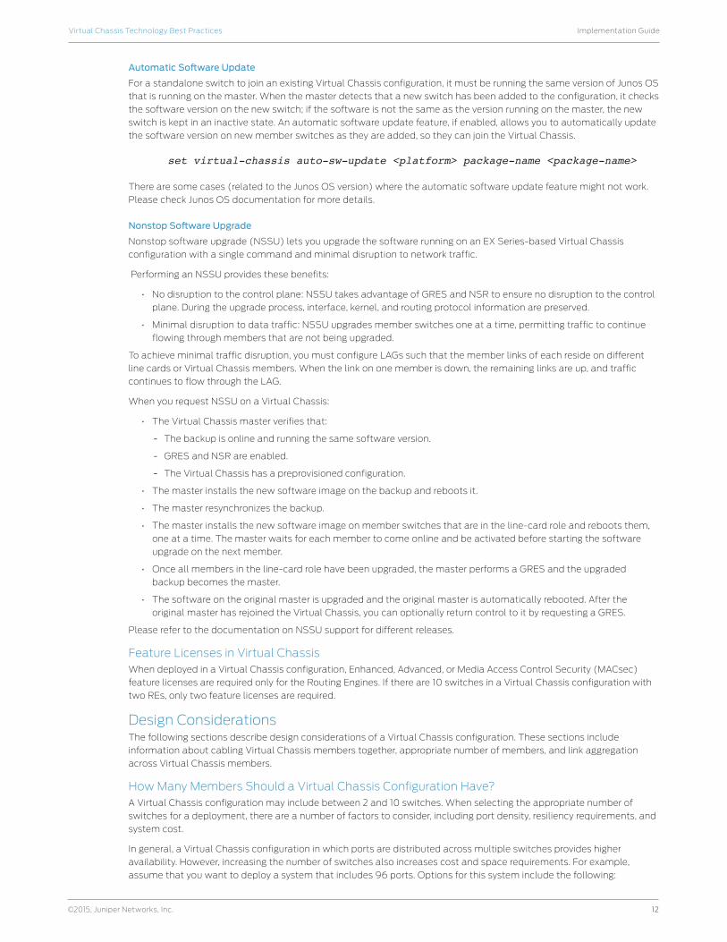
Figure 5 illustrates the recommended location of the master and backup switches in a daisy-chained ring cabling
configuration.
Line Card (LC)
Backup (RE1)
Line Card (LC)
Master (RE0)
Figure 5: Recommended member location in a daisy-chained ring deployment
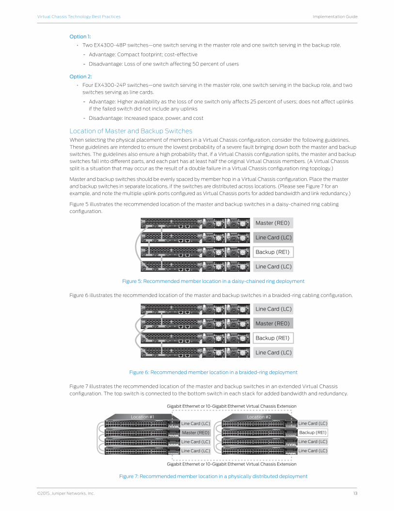
Figure 6 illustrates the recommended location of the master and backup switches in a braided-ring cabling configuration.
Line Card (LC)
Backup (RE1)
Line Card (LC)
Master (RE0)
Figure 6: Recommended member location in a braided-ring deployment
Figure 7 illustrates the recommended location of the master and backup switches in an extended Virtual Chassis
configuration. The top switch is connected to the bottom switch in each stack for added bandwidth and redundancy.
0 1 2 3 4 5 6 7 8 9 10 11 12 13 14 15 16 17 18 19 20 21 22 23 24 25 26 27 28 29 30 31 32 33 34 35 36 37 38 39 40 41 42 43 44 45 46 47
48PoEEX4200 Series
0 1 2 3 4 5 6 7 8 9 10 11 12 13 14 15 16 17 18 19 20 21 22 23 24 25 26 27 28 29 30 31 32 33 34 35 36 37 38 39 40 41 42 43 44 45 46 47
48PoEEX4200 Series
0 1 2 3 4 5 6 7 8 9 10 11 12 13 14 15 16 17 18 19 20 21 22 23 24 25 26 27 28 29 30 31 32 33 34 35 36 37 38 39 40 41 42 43 44 45 46 47
48PoEEX4200 Series
0 1 2 3 4 5 6 7 8 9 10 11 12 13 14 15 16 17 18 19 20 21 22 23 24 25 26 27 28 29 30 31 32 33 34 35 36 37 38 39 40 41 42 43 44 45 46 47
48PoEEX4200 Series
Line Card (LC)
Line Card (LC)
Gigabit Ethernet or 10-Gigabit Ethernet Virtual Chassis Extension
Location #1
Master (RE0)
Line Card (LC)
0 1 2 3 4 5 6 7 8 9 10 11 12 13 14 15 16 17 18 19 20 21 22 23 24 25 26 27 28 29 30 31 32 33 34 35 36 37 38 39 40 41 42 43 44 45 46 47
48PoEEX4200 Series
0 1 2 3 4 5 6 7 8 9 10 11 12 13 14 15 16 17 18 19 20 21 22 23 24 25 26 27 28 29 30 31 32 33 34 35 36 37 38 39 40 41 42 43 44 45 46 47
48PoEEX4200 Series
0 1 2 3 4 5 6 7 8 9 10 11 12 13 14 15 16 17 18 19 20 21 22 23 24 25 26 27 28 29 30 31 32 33 34 35 36 37 38 39 40 41 42 43 44 45 46 47
48PoEEX4200 Series
0 1 2 3 4 5 6 7 8 9 10 11 12 13 14 15 16 17 18 19 20 21 22 23 24 25 26 27 28 29 30 31 32 33 34 35 36 37 38 39 40 41 42 43 44 45 46 47
48PoEEX4200 Series
Line Card (LC)
Line Card (LC)
Backup (RE1)
Line Card (LC)
Gigabit Ethernet or 10-Gigabit Ethernet Virtual Chassis Extension
Location #2
Figure 7: Recommended member location in a physically distributed deployment
14
Implementation GuideVirtual Chassis Technology Best Practices
©2015, Juniper Networks, Inc.
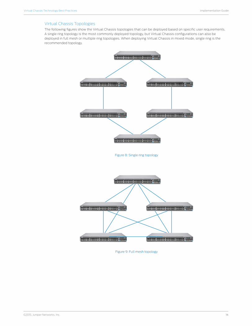
Virtual Chassis TopologiesThe following figures show the Virtual Chassis topologies that can be deployed based on specific user requirements.
A single ring topology is the most commonly deployed topology, but Virtual Chassis configurations can also be
deployed in full mesh or multiple ring topologies. When deploying Virtual Chassis in mixed mode, single ring is the
recommended topology.
Figure 8: Single ring topology
Figure 9: Full mesh topology
15
Implementation GuideVirtual Chassis Technology Best Practices
©2015, Juniper Networks, Inc.
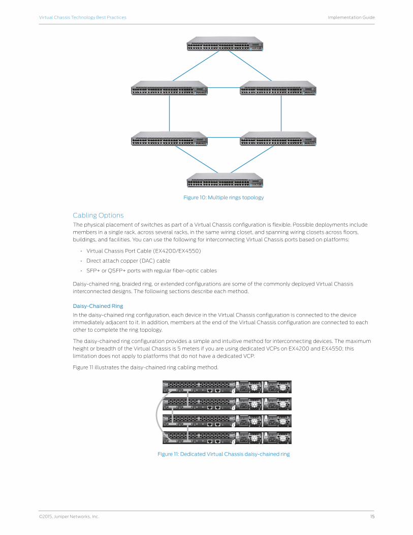
Figure 10: Multiple rings topology
Cabling Options The physical placement of switches as part of a Virtual Chassis configuration is flexible. Possible deployments include
members in a single rack, across several racks, in the same wiring closet, and spanning wiring closets across floors,
buildings, and facilities. You can use the following for interconnecting Virtual Chassis ports based on platforms:
• Virtual Chassis Port Cable (EX4200/EX4550)
• Direct attach copper (DAC) cable
• SFP+ or QSFP+ ports with regular fiber-optic cables
Daisy-chained ring, braided ring, or extended configurations are some of the commonly deployed Virtual Chassis
interconnected designs. The following sections describe each method.
Daisy-Chained Ring
In the daisy-chained ring configuration, each device in the Virtual Chassis configuration is connected to the device
immediately adjacent to it. In addition, members at the end of the Virtual Chassis configuration are connected to each
other to complete the ring topology.
The daisy-chained ring configuration provides a simple and intuitive method for interconnecting devices. The maximum
height or breadth of the Virtual Chassis is 5 meters if you are using dedicated VCPs on EX4200 and EX4550; this
limitation does not apply to platforms that do not have a dedicated VCP.
Figure 11 illustrates the daisy-chained ring cabling method.
5m
Figure 11: Dedicated Virtual Chassis daisy-chained ring
16
Implementation GuideVirtual Chassis Technology Best Practices
©2015, Juniper Networks, Inc.
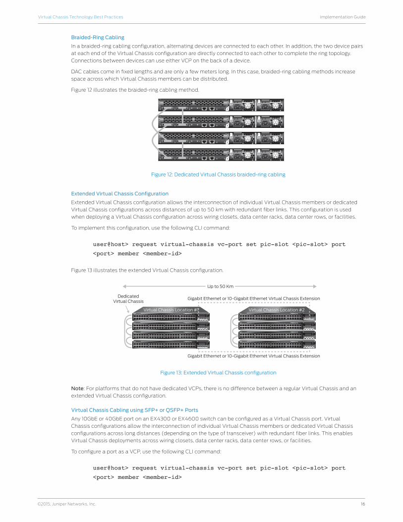
Braided-Ring Cabling
In a braided-ring cabling configuration, alternating devices are connected to each other. In addition, the two device pairs
at each end of the Virtual Chassis configuration are directly connected to each other to complete the ring topology.
Connections between devices can use either VCP on the back of a device.
DAC cables come in fixed lengths and are only a few meters long. In this case, braided-ring cabling methods increase
space across which Virtual Chassis members can be distributed.
Figure 12 illustrates the braided-ring cabling method.
22.5m
Figure 12: Dedicated Virtual Chassis braided-ring cabling
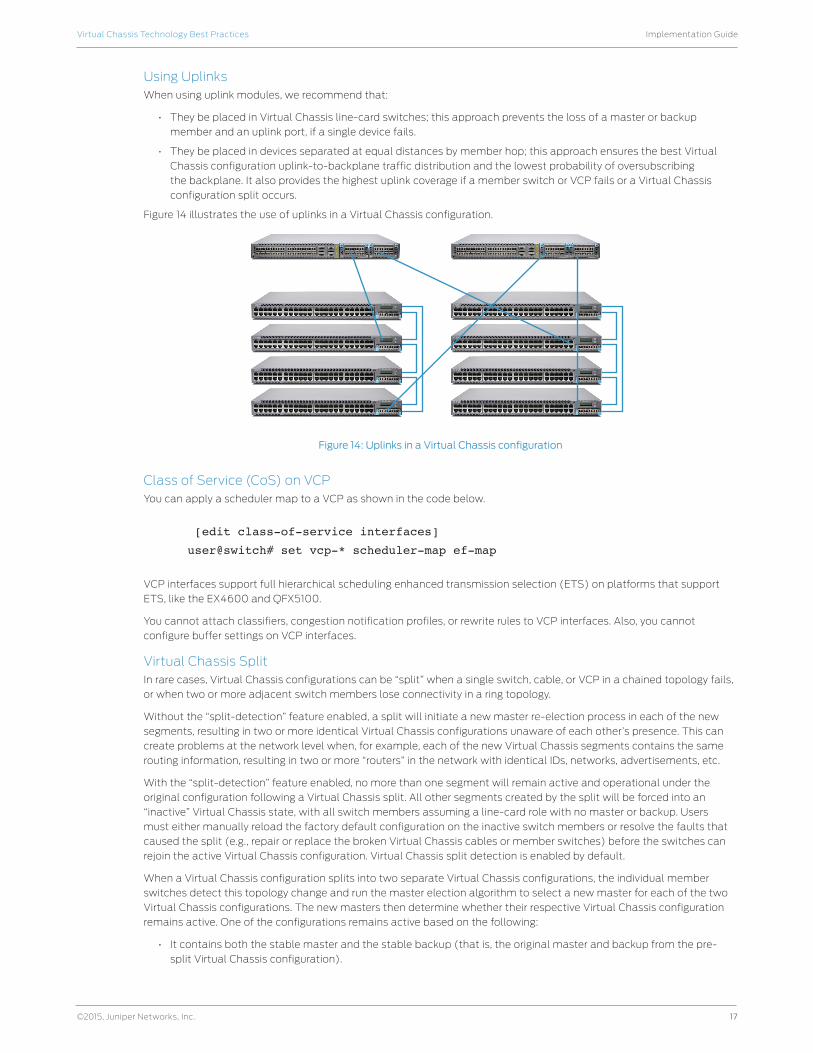
Extended Virtual Chassis Configuration
Extended Virtual Chassis configuration allows the interconnection of individual Virtual Chassis members or dedicated
Virtual Chassis configurations across distances of up to 50 km with redundant fiber links. This configuration is used
when deploying a Virtual Chassis configuration across wiring closets, data center racks, data center rows, or facilities.
To implement this configuration, use the following CLI command:
user@host> request virtual-chassis vc-port set pic-slot <pic-slot> port
<port> member <member-id>
Figure 13 illustrates the extended Virtual Chassis configuration.
0 1 2 3 4 5 6 7 8 9 10 11 12 13 14 15 16 17 18 19 20 21 22 23 24 25 26 27 28 29 30 31 32 33 34 35 36 37 38 39 40 41 42 43 44 45 46 47
48PoEEX4200 Series
0 1 2 3 4 5 6 7 8 9 10 11 12 13 14 15 16 17 18 19 20 21 22 23 24 25 26 27 28 29 30 31 32 33 34 35 36 37 38 39 40 41 42 43 44 45 46 47
48PoEEX4200 Series
0 1 2 3 4 5 6 7 8 9 10 11 12 13 14 15 16 17 18 19 20 21 22 23 24 25 26 27 28 29 30 31 32 33 34 35 36 37 38 39 40 41 42 43 44 45 46 47
48PoEEX4200 Series
0 1 2 3 4 5 6 7 8 9 10 11 12 13 14 15 16 17 18 19 20 21 22 23 24 25 26 27 28 29 30 31 32 33 34 35 36 37 38 39 40 41 42 43 44 45 46 47
48PoEEX4200 Series
Gigabit Ethernet or 10-Gigabit Ethernet Virtual Chassis ExtensionDedicatedVirtual Chassis
Virtual Chassis Location #1
0 1 2 3 4 5 6 7 8 9 10 11 12 13 14 15 16 17 18 19 20 21 22 23 24 25 26 27 28 29 30 31 32 33 34 35 36 37 38 39 40 41 42 43 44 45 46 47
48PoEEX4200 Series
0 1 2 3 4 5 6 7 8 9 10 11 12 13 14 15 16 17 18 19 20 21 22 23 24 25 26 27 28 29 30 31 32 33 34 35 36 37 38 39 40 41 42 43 44 45 46 47
48PoEEX4200 Series
0 1 2 3 4 5 6 7 8 9 10 11 12 13 14 15 16 17 18 19 20 21 22 23 24 25 26 27 28 29 30 31 32 33 34 35 36 37 38 39 40 41 42 43 44 45 46 47
48PoEEX4200 Series
0 1 2 3 4 5 6 7 8 9 10 11 12 13 14 15 16 17 18 19 20 21 22 23 24 25 26 27 28 29 30 31 32 33 34 35 36 37 38 39 40 41 42 43 44 45 46 47
48PoEEX4200 Series
Gigabit Ethernet or 10-Gigabit Ethernet Virtual Chassis Extension
Virtual Chassis Location #2
Up to 50 Km
Figure 13: Extended Virtual Chassis configuration
Note: For platforms that do not have dedicated VCPs, there is no difference between a regular Virtual Chassis and an
extended Virtual Chassis configuration.
Virtual Chassis Cabling using SFP+ or QSFP+ Ports
Any 10GbE or 40GbE port on an EX4300 or EX4600 switch can be configured as a Virtual Chassis port. Virtual
Chassis configurations allow the interconnection of individual Virtual Chassis members or dedicated Virtual Chassis
configurations across long distances (depending on the type of transceiver) with redundant fiber links. This enables
Virtual Chassis deployments across wiring closets, data center racks, data center rows, or facilities.
To configure a port as a VCP, use the following CLI command:
user@host> request virtual-chassis vc-port set pic-slot <pic-slot> port
<port> member <member-id>
17
Implementation GuideVirtual Chassis Technology Best Practices
©2015, Juniper Networks, Inc.
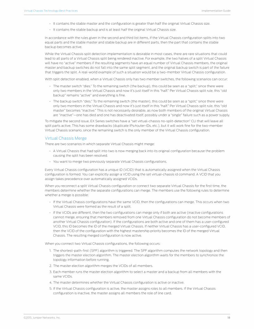
Using UplinksWhen using uplink modules, we recommend that:
• They be placed in Virtual Chassis line-card switches; this approach prevents the loss of a master or backup
member and an uplink port, if a single device fails.
• They be placed in devices separated at equal distances by member hop; this approach ensures the best Virtual
Chassis configuration uplink-to-backplane traffic distribution and the lowest probability of oversubscribing
the backplane. It also provides the highest uplink coverage if a member switch or VCP fails or a Virtual Chassis
configuration split occurs.
Figure 14 illustrates the use of uplinks in a Virtual Chassis configuration.
Figure 14: Uplinks in a Virtual Chassis configuration
Class of Service (CoS) on VCPYou can apply a scheduler map to a VCP as shown in the code below.
[edit class-of-service interfaces]
user@switch# set vcp-* scheduler-map ef-map
VCP interfaces support full hierarchical scheduling enhanced transmission selection (ETS) on platforms that support
ETS, like the EX4600 and QFX5100.
You cannot attach classifiers, congestion notification profiles, or rewrite rules to VCP interfaces. Also, you cannot
configure buffer settings on VCP interfaces.
Virtual Chassis SplitIn rare cases, Virtual Chassis configurations can be “split” when a single switch, cable, or VCP in a chained topology fails,
or when two or more adjacent switch members lose connectivity in a ring topology.
Without the “split-detection” feature enabled, a split will initiate a new master re-election process in each of the new
segments, resulting in two or more identical Virtual Chassis configurations unaware of each other’s presence. This can
create problems at the network level when, for example, each of the new Virtual Chassis segments contains the same
routing information, resulting in two or more “routers” in the network with identical IDs, networks, advertisements, etc.
With the “split-detection” feature enabled, no more than one segment will remain active and operational under the
original configuration following a Virtual Chassis split. All other segments created by the split will be forced into an
“inactive” Virtual Chassis state, with all switch members assuming a line-card role with no master or backup. Users
must either manually reload the factory default configuration on the inactive switch members or resolve the faults that
caused the split (e.g., repair or replace the broken Virtual Chassis cables or member switches) before the switches can
rejoin the active Virtual Chassis configuration. Virtual Chassis split detection is enabled by default.
When a Virtual Chassis configuration splits into two separate Virtual Chassis configurations, the individual member
switches detect this topology change and run the master election algorithm to select a new master for each of the two
Virtual Chassis configurations. The new masters then determine whether their respective Virtual Chassis configuration
remains active. One of the configurations remains active based on the following:
• It contains both the stable master and the stable backup (that is, the original master and backup from the pre-
split Virtual Chassis configuration).
18
Implementation GuideVirtual Chassis Technology Best Practices
©2015, Juniper Networks, Inc.
• It contains the stable master and the configuration is greater than half the original Virtual Chassis size.
• It contains the stable backup and is at least half the original Virtual Chassis size.
In accordance with the rules given in the second and third list items, if the Virtual Chassis configuration splits into two
equal parts and the stable master and stable backup are in different parts, then the part that contains the stable
backup becomes active.
While the Virtual Chassis split detection implementation is desirable in most cases, there are rare situations that could
lead to all parts of a Virtual Chassis split being rendered inactive. For example, the two halves of a split Virtual Chassis
will have no “active” members if the resulting segments have an equal number of Virtual Chassis members, the original
master and backup switches do not fall into the same split segment, and the original backup switch is part of the failure
that triggers the split. A real-world example of such a situation would be a two-member Virtual Chassis configuration.
With split detection enabled, when a Virtual Chassis only has two member switches, the following scenarios can occur:
• The master switch “dies.” To the remaining switch (the backup), this could be seen as a “split,” since there were
only two members in the Virtual Chassis and now it’s just itself in this “half.” Per Virtual Chassis split rule, this “old
backup” remains “active” and everything is fine.
• The backup switch “dies.” To the remaining switch (the master), this could be seen as a “split,” since there were
only two members in the Virtual Chassis and now it’s just itself in this “half.” Per Virtual Chassis split rule, this “old
master” becomes “inactive.” This is not necessarily desirable, as now both members of the original Virtual Chassis
are “inactive”—one has died and one has deactivated itself, possibly under a “single” failure such as a power supply.
To mitigate the second issue, EX Series switches have a “set virtual-chassis no-split-detection” CLI that will leave all
split parts active. This has some drawbacks (duplicate IPs/router-IDs, etc.), but it will work fine for the two-member
Virtual Chassis scenario, since the remaining switch is the only member of the Virtual Chassis configuration.
Virtual Chassis MergeThere are two scenarios in which separate Virtual Chassis might merge:
• A Virtual Chassis that had split into two is now merging back into its original configuration because the problem
causing the split has been resolved.
• You want to merge two previously separate Virtual Chassis configurations.
Every Virtual Chassis configuration has a unique ID (VCID) that is automatically assigned when the Virtual Chassis
configuration is formed. You can explicitly assign a VCID using the set virtual-chassis id command. A VCID that you
assign takes precedence over automatically assigned VCIDs.
When you reconnect a split Virtual Chassis configuration or connect two separate Virtual Chassis for the first time, the
members determine whether the separate configurations can merge. The members use the following rules to determine
whether a merge is possible:
• If the Virtual Chassis configurations have the same VCID, then the configurations can merge. This occurs when two
Virtual Chassis were formed as the result of a split.
• If the VCIDs are different, then the two configurations can merge only if both are active (inactive configurations
cannot merge, ensuring that members removed from one Virtual Chassis configuration do not become members of
another Virtual Chassis configuration). If the configurations are both active and one of them has a user-configured
VCID, this ID becomes the ID of the merged Virtual Chassis. If neither Virtual Chassis has a user-configured VCID,
then the VCID of the configuration with the highest mastership priority becomes the ID of the merged Virtual
Chassis. The resulting merged configuration is now active.
When you connect two Virtual Chassis configurations, the following occurs:
1. The shortest-path-first (SPF) algorithm is triggered. The SPF algorithm computes the network topology and then
triggers the master election algorithm. The master election algorithm waits for the members to synchronize the
topology information before running.
2. The master election algorithm merges the VCIDs of all members.
3. Each member runs the master election algorithm to select a master and a backup from all members with the
same VCIDs.
4. The master determines whether the Virtual Chassis configuration is active or inactive.
5. If the Virtual Chassis configuration is active, the master assigns roles to all members. If the Virtual Chassis
configuration is inactive, the master assigns all members the role of line card.
19
Implementation GuideVirtual Chassis Technology Best Practices
©2015, Juniper Networks, Inc.
6. When the other members receive their role from the master, they change their role to backup or line card. They also
use the active or inactive state information sent by the master to set their own state and to construct the Virtual
Chassis member list from the information sent by the master.
7. If the Virtual Chassis state is active, the master waits for messages from the members indicating that they have
changed to their assigned roles. The master then changes its own role to “master.”
ImplementationThe following sections describe options for installing a Virtual Chassis configuration. There are two methods for
installing and configuring Virtual Chassis technology: non-provisioned and preprovisioned.
Non-Provisioned Mode InstallationUse the non-provisioned installation method to build a Virtual Chassis configuration or to add a new member to an
existing Virtual Chassis configuration without prior user configuration. Although it is not required, we recommend that
the master and backup switches be designated by configuring the mastership priority of these switches to be the highest
value of all members.
We also recommend that factory defaults be loaded on all members before adding these switches to the Virtual Chassis
configuration, as this prevents unexpected behavior when adding new members. Factory defaults can be loaded by
using either of the following configuration mode CLI commands:
user@host# load factory-default
user@host# set system root-authentication plain-password
(Follow the prompts to configure a root password to apply the change.)
user@ host#commit
Using the LCD Menus on a Switch
To perform a non-provisioned installation, follow these general steps.
1. Begin by installing the switch you want to be the master by taking these actions:
a. Install required power supplies.
b. Place the switch in the desired location.
c. Power up the switch and load the factory default configuration.
d. Assign the highest mastership priority to the switch.
This switch becomes the master and obtains a member ID of 0.
2. For each switch you want to be a line-card switch, take these actions:
a. Install required power supplies.
b. Power up the switch and load the factory default configuration.
c. If you do not want to use the default VCPs, you can manually configure some of the 10GbE or 40GbE ports as
VCPs.
d. Power off the switch.
e. Place the switch in the desired location.
f. Connect the switch to existing members of the Virtual Chassis using VCPs.
g. Power up the switch.
h. Repeat these steps as needed to install additional line-card switches.
The mastership election process assigns the switch the next lowest available member ID based on the order in which
the switch is added to the Virtual Chassis configuration. The switch may be temporarily configured as the backup
switch (because the proposed backup switch has not yet been added to the Virtual Chassis configuration). The switch
becomes a line card when the actual backup switch is installed.
20
Implementation GuideVirtual Chassis Technology Best Practices
©2015, Juniper Networks, Inc.
3. For the switch you want to be the backup switch in the Virtual Chassis configuration, take these actions:
a. Install required power supplies.
b. Power up the switch and load the factory default configuration.
c. Power off the switch.
d. Place the switch in the desired location.
e. Connect the switch to existing members of the Virtual Chassis configuration with a VCP cable.
f. Power up the switch.
The mastership election process assigns the switch the next lowest available member ID based on the order that the
switch is added to the Virtual Chassis configuration.
g. Assign this switch the same mastership priority as the master switch. Doing so prevents mastership preemption
if the master fails and then recovers.
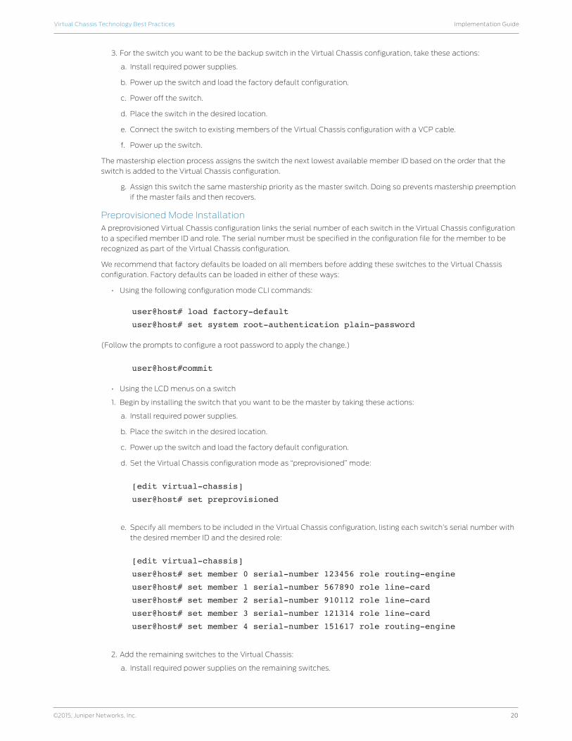
Preprovisioned Mode InstallationA preprovisioned Virtual Chassis configuration links the serial number of each switch in the Virtual Chassis configuration
to a specified member ID and role. The serial number must be specified in the configuration file for the member to be
recognized as part of the Virtual Chassis configuration.
We recommend that factory defaults be loaded on all members before adding these switches to the Virtual Chassis
configuration. Factory defaults can be loaded in either of these ways:
• Using the following configuration mode CLI commands:
user@host# load factory-default
user@host# set system root-authentication plain-password
(Follow the prompts to configure a root password to apply the change.)
user@host#commit
• Using the LCD menus on a switch
1. Begin by installing the switch that you want to be the master by taking these actions:
a. Install required power supplies.
b. Place the switch in the desired location.
c. Power up the switch and load the factory default configuration.
d. Set the Virtual Chassis configuration mode as “preprovisioned” mode:
[edit virtual-chassis]
user@host# set preprovisioned
e. Specify all members to be included in the Virtual Chassis configuration, listing each switch’s serial number with
the desired member ID and the desired role:
[edit virtual-chassis]
user@host# set member 0 serial-number 123456 role routing-engine
user@host# set member 1 serial-number 567890 role line-card
user@host# set member 2 serial-number 910112 role line-card
user@host# set member 3 serial-number 121314 role line-card
user@host# set member 4 serial-number 151617 role routing-engine
2. Add the remaining switches to the Virtual Chassis:
a. Install required power supplies on the remaining switches.
21
Implementation GuideVirtual Chassis Technology Best Practices
©2015, Juniper Networks, Inc.
b. Power up the switches and load the factory default configuration.
c. Power off the switches.
d. Place the switches in the desired locations.
e. Connect the VCPs.
f. Power up the switches.
g. These switches should now be part of the Virtual Chassis and should be assigned roles based on their serial
number.
Managing and Maintaining a Virtual Chassis ConfigurationThe following sections provide information about adding or replacing member switches, as well as guidance for a variety
of other maintenance operations.
Note: Some maintenance operations require connecting to the Virtual Chassis configuration through a console so that
you can issue CLI commands. If you connect through a console to a Virtual Chassis member other than the master
switch, the connection redirects to the master switch automatically.
Adding a New Switch to an Existing Virtual Chassis Configuration in the Same Wiring Closet
This section describes how to add a new switch to a Virtual Chassis configuration when the new switch is installed in the
same wiring closet as the other Virtual Chassis switch members. Before beginning:
• Install required power supplies and uplink modules in the new switch.
• Place the new switch in the desired location.
• Confirm that the new switch is powered off.
If expanding a preprovisioned configuration, make a note of the serial number on the back of the switch. Then edit the
existing Virtual Chassis preprovisioning configuration to include the serial number and the role of the new switch.
To add the new switch, follow these steps:
1. If the new member switch was previously configured, power it on, reset the configuration to the factory default
values, and then power it off.
2. Interconnect the unpowered new switch to at least one member of the existing Virtual Chassis configuration by
using the VCPs.
3. Power on the new switch.
4. Confirm that the new switch is now included in the Virtual Chassis configuration by checking the front-panel LCD
for the member ID. It should display a member ID that is higher than 0 because there are already at least two
members of the Virtual Chassis configuration.
Note: If you are using a preprovisioned configuration, the member ID is assigned to the serial number of the member in
the configuration file.
Replacing a Member Switch
A member switch may be replaced in a Virtual Chassis configuration with little loss of traffic. When a switch is replaced,
the configuration of the replaced switch is retained and may be applied to the new switch, if desired.
The following sections describe how to replace a member switch in a variety of situations.
Note: A replacement switch does not inherit the configuration of the previous switch if its member ID changes.
Removing, Repairing, and Reinstalling the Same Switch
If a member switch needs to be replaced, it can be removed from the Virtual Chassis configuration with little loss of
traffic. The master switch stores the configuration, including the member ID of the removed switch, so that it can be
reapplied when the switch (with the same MAC address) is reconnected.
To remove, repair, and reinstall a switch, follow these steps:
1. Power off and disconnect the switch.
2. Repair the switch, as necessary.
3. Reconnect and power on the switch.
22
Implementation GuideVirtual Chassis Technology Best Practices
©2015, Juniper Networks, Inc.
Removing a Member Switch, Replacing it with a Different Switch, and Reapplying the Old Configuration
A member switch may be replaced with a different switch that retains the configuration of the original switch. The
master switch stores the configuration of the member that was removed. When a replacement member switch is
connected, the master switch assigns it a new member ID. The old configuration remains stored under the member
ID of the previous switch. Renumbering the replacement switch with the member ID of the old switch applies the
configuration of the old switch to the replacement switch.
To replace a switch and reapply configuration, perform the following steps:
1. Power off and disconnect the switch to be replaced.
2. If the replacement switch has been previously configured, reset its configuration to the factory default values. (For
instructions about how to load factory default values, please see the “Non-Provisioned Installation” section.)
3. Connect the replacement switch in place of the old switch and power it on.
4. Note the member ID that displays on the front-panel LCD. It should be the next lowest member ID that was
available before the replacement.
5. Use the following CLI command to change the current member ID of the replacement switch to the member ID of
the switch that you removed:
user@host> request virtual-chassis renumber member-id <member-id> new-
member-id <member-id>
6. If you used a preprovisioned configuration, use the following CLI command to change the relevant serial number in
the Virtual Chassis configuration file. Substitute the serial number of the replacement switch (on the back of the
switch) for the serial number of the switch that was removed.
user@host# set virtual-chassis pre-provisioned member <removed member-id>
serial-number <replacement switch serial number> role <removed member old
role>
Removing a Member Switch and Making Its Member ID Available for Reassignment to a Different Switch
When removing a member switch from the Virtual Chassis configuration, the master switch keeps the member ID of that
switch in reserve.
In addition, the configuration of the old switch applies only to the valid parts of the new member. For example, if a 24-
port switch is replaced with a 48-port switch, the old configuration applies to the first 24 ports of the new switch. The
other ports have no configuration.
Virtual Chassis ManagementA Virtual Chassis configuration is composed of multiple switches; therefore, it offers multiple console ports and multiple
out-of-band management Ethernet ports on the switches. Following are some ways to access the CLI on a Virtual
Chassis.
• Console: You can connect a PC or laptop directly to a console port of any member switch to set up and configure
the Virtual Chassis. When you connect to the console port of any member switch, the console session is redirected
to the master switch.
• Out-of-band management: An out-of-band management Ethernet port is often referred to simply as a
management Ethernet port. It uses a dedicated management channel for device maintenance and allows a
system administrator to monitor and manage the switch by remote control.
The Virtual Chassis configuration can also be managed remotely through SSH or Telnet using a global management
interface called the virtual management Ethernet (VME) interface. The VME interface is a logical interface representing
all of the out-of-band management ports on the member switches. When you connect to the Virtual Chassis
configuration using the VME interface’s IP address, the connection is redirected to the master member. This VME
interface is a logical IP interface associated with the Virtual Chassis internal management VLAN that connects the me0
interfaces of all member switches in a Virtual Chassis configuration. To assign an IP address, use these CLI commands:
user@host> configure
user@host# set interfaces vme unit 0 family inet address <ip-
address>/<subnet-mask>
23
Implementation GuideVirtual Chassis Technology Best Practices
©2015, Juniper Networks, Inc.
If the master management Ethernet link is unavailable, the session is redirected through the backup management Ethernet
link. If there is no active management Ethernet link on the backup, the VME interface chooses a management Ethernet link
on one of the line-card members, selecting the line-card member with the lowest member ID as its first choice.
You can configure an IP address for the VME global management interface.
• In-band management: If the Virtual Chassis configuration has a Layer 3 interface like a routed VLAN interface (RVI)
or an integrated routing and bridging interface (IRB), it can be managed remotely through SSH or Telnet using the
Layer 3 IP address.
Synchronizing Virtual Chassis MembersVirtual Chassis configurations have two Routing Engines, one in the master and the other in the backup. Therefore, we
recommend using the “commit synchronize” command rather than simply committing to save configuration changes
made to a Virtual Chassis. This ensures that the configuration changes are saved in both REs.
In a Virtual Chassis environment, committing the configuration by “commit” command only commits the configuration
on the master. To synchronize the configuration on all other Virtual Chassis members, the “commit synchronize”
command needs to be executed each time. This default behavior can be changed by adding “set system commit
synchronize” to the existing configuration.
Loading Factory Default SettingsEX Series and QFX Series switches are programmed with a factory default configuration stored in a default configuration
file. This default configuration includes values for system parameters such as system logging and commit, configures
Power over Ethernet (PoE) and Ethernet switching on all interfaces, and enables Link Layer Discovery Protocol (LLDP)
and Rapid Spanning Tree Protocol (RSTP).
When committing changes to the configuration, a new configuration is created and becomes active. You can revert to
the factory default configuration at any time.
Virtual Chassis FailoverUnlike chassis-based systems, there are no fabric links or switch fabrics in these platforms. Most of the hardware
failures, such as power supplies or fans, will result in a system halt.
• VCP link failure: If the VCP link goes down, VCCP can detect this failure and recalculate the alternate path for
Virtual Chassis traffic. When fast failover is activated, each VCP is automatically configured with a backup port of
the same type (dedicated VCP, SFP uplink VCP, or 10-gigabit small form-factor pluggable transceiver uplink VCP).
If a VCP fails, its backup port is used to send traffic. These backup ports act as standby ports and are not meant for
load-balancing traffic or any other purpose.
• Virtual Chassis member power down: Virtual Chassis member shutdown will have the same effect as a VCP link
failure. The neighbors detect the physical links going down and recalculate alternate paths or use a backup port if
fast failover is activated.
• PFE failure: In those rare cases where a PFE failure occurs and the VCP link does not go down physically, VCCP will
detect this failure based on the timeout for VCCP hello messages. VCCP hellos are exchanged every second; if the
neighbor does not receive these hellos for 10 consecutive intervals, the neighbor is assumed to be down and VCCP
recalculates alternate paths.
Monitoring a Virtual Chassis ConfigurationThe following sections provide information about monitoring the operation of a Virtual Chassis configuration.
Monitoring Operation with CLI CommandsThe Junos OS CLI provides commands which display information for all members in a Virtual Chassis configuration or for
a specific member.
To view member details for all members in a Virtual Chassis configuration, enter the following CLI command:
user@host> show virtual-chassis status
This command displays the following information:
• Virtual Chassis ID
• Member ID
• Status
• Serial number
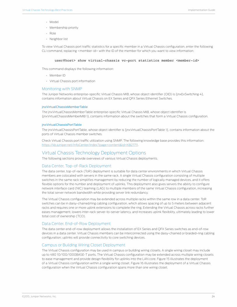
24
Implementation GuideVirtual Chassis Technology Best Practices
©2015, Juniper Networks, Inc.
• Model
• Membership priority
• Role
• Neighbor list
To view Virtual Chassis port traffic statistics for a specific member in a Virtual Chassis configuration, enter the following
CLI command, replacing <member-id> with the ID of the member for which you want to view information:
user@host> show virtual-chassis vc-port statistics member <member-id>
This command displays the following information:
• Member ID
• Virtual Chassis port information
Monitoring with SNMPThe Juniper Networks enterprise-specific Virtual Chassis MIB, whose object identifier (OID) is {jnxExSwitching 4},
contains information about Virtual Chassis on EX Series and QFX Series Ethernet Switches.
jnxVirtualChassisMemberTable
The jnxVirtualChassisMemberTable enterprise-specific Virtual Chassis MIB, whose object identifier is
{jnxVirtualChassisMemberMIB 1}, contains information about the switches that form a Virtual Chassis configuration.
jnxVirtualChassisPortTable
The jnxVirtualChassisPortTable, whose object identifier is {jnxVirtualChassisPortTable 1}, contains information about the
ports of Virtual Chassis member switches.
Check Virtual Chassis port traffic utilization using SNMP. The following knowledge base provides this information:
https://kb.juniper.net/InfoCenter/index?page=content&id=KB27711.
Virtual Chassis Technology Deployment OptionsThe following sections provide overviews of various Virtual Chassis deployments.
Data Center, Top-of-Rack DeploymentThe data center, top-of-rack (ToR) deployment is suitable for data center environments in which Virtual Chassis
members are colocated with servers in the same rack. A single Virtual Chassis configuration consisting of multiple
switches in the same rack simplifies management by reducing the number of logically managed devices, and it offers
flexible options for the number and deployment of uplinks. This deployment also gives servers the ability to configure
network interface card (NIC) teaming (LAG) to multiple members of the same Virtual Chassis configuration, increasing
the total server network bandwidth while providing server link redundancy.
The Virtual Chassis configuration may be extended across multiple racks within the same row in a data center. ToR
switches can be in daisy-chained/ring cabling configuration, which allows spacing of up to 5 meters between adjacent
racks and requires one or more uplink extensions to complete the ring. Extending the Virtual Chassis across racks further
eases management, lowers inter-rack server-to-server latency, and increases uplink flexibility, ultimately leading to lower
total cost of ownership (TCO).
Data Center, End-of-Row DeploymentThe data center end-of-row deployment allows the installation of EX Series and QFX Series switches as end-of-row
devices in a data center. Virtual Chassis members can be interconnected using the daisy-chained or braided-ring cabling
configuration; uplinks will provide connectivity to core switching devices.
Campus or Building Wiring Closet DeploymentThe Virtual Chassis configuration may be used in campus or building wiring closets. A single wiring closet may include
up to 480 10/100/1000BASE-T ports. The Virtual Chassis configuration may be extended across multiple wiring closets
to ease management and provide design flexibility for uplinks into the LAN core. Figure 15 illustrates the deployment
of a Virtual Chassis configuration within a single wiring closet. Figure 16 illustrates the deployment of a Virtual Chassis
configuration when the Virtual Chassis configuration spans more than one wiring closet.
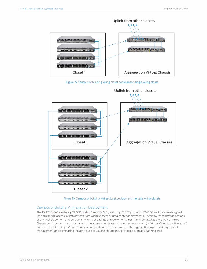
25
Implementation GuideVirtual Chassis Technology Best Practices
©2015, Juniper Networks, Inc.
Closet 1 Aggregation Virtual Chassis
Uplink from other closets
Figure 15: Campus or building wiring closet deployment, single wiring closet
Closet 1
Closet 2
Aggregation Virtual Chassis
Uplink from other closets
Figure 16: Campus or building wiring closet deployment, multiple wiring closets
Campus or Building Aggregation DeploymentThe EX4200-24F (featuring 24 SFP ports), EX4300-32F (featuring 32 SFP ports), or EX4600 switches are designed
for aggregating access switch devices from wiring closets or data center deployments. These switches provide options
of physical placement and port density to meet a range of requirements. For maximum availability, a pair of Virtual
Chassis configurations can be located in the aggregation layer with each access switch (or Virtual Chassis configuration)
dual-homed. Or, a single Virtual Chassis configuration can be deployed at the aggregation layer, providing ease of
management and eliminating the active use of Layer 2 redundancy protocols such as Spanning Tree.
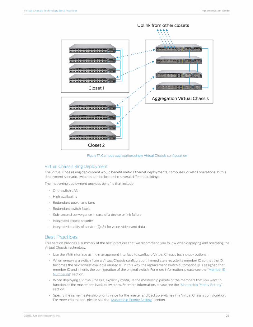
26
Implementation GuideVirtual Chassis Technology Best Practices
©2015, Juniper Networks, Inc.
Closet 1
Closet 2
Aggregation Virtual Chassis
Uplink from other closets
Figure 17: Campus aggregation, single Virtual Chassis configuration
Virtual Chassis Ring DeploymentThe Virtual Chassis ring deployment would benefit metro Ethernet deployments, campuses, or retail operations. In this
deployment scenario, switches can be located in several different buildings.
The metro/ring deployment provides benefits that include:
• One-switch LAN
• High availability
• Redundant power and fans
• Redundant switch fabric
• Sub-second convergence in case of a device or link failure
• Integrated access security
• Integrated quality of service (QoS) for voice, video, and data
Best PracticesThis section provides a summary of the best practices that we recommend you follow when deploying and operating the
Virtual Chassis technology.
• Use the VME interface as the management interface to configure Virtual Chassis technology options.
• When removing a switch from a Virtual Chassis configuration, immediately recycle its member ID so that the ID
becomes the next lowest available unused ID. In this way, the replacement switch automatically is assigned that
member ID and inherits the configuration of the original switch. For more information, please see the “Member ID
Numbering” section.
• When deploying a Virtual Chassis, explicitly configure the mastership priority of the members that you want to
function as the master and backup switches. For more information, please see the “Mastership Priority Setting”
section.
• Specify the same mastership priority value for the master and backup switches in a Virtual Chassis configuration.
For more information, please see the “Mastership Priority Setting” section.

27
Implementation GuideVirtual Chassis Technology Best Practices
©2015, Juniper Networks, Inc.
• Configure the highest possible mastership priority value (255) for the master and backup switches. For more
information, please see the “Mastership Priority Setting” section.
• When designing a Virtual Chassis configuration, consider a deployment in which ports are distributed across as
many switches as possible to provide the highest resiliency and the smallest failure domain. For more information,
please see the “How Many Members Should a Virtual Chassis Configuration Have?” section.
• Evenly space master and backup switches by member hop when possible. For more information, please see the
“Location of Master and Backup Switches” section.
• Place the master and backup switches in separate locations when deploying an extended Virtual Chassis
configuration. For more information, please see the “Location of Master and Backup Switches” section.
• For maximum resiliency, interconnect Virtual Chassis member devices in a ring topology. For more information,
please see the “Cabling Options” section.
• When possible, place uplink modules in the Virtual Chassis configuration line-card switches, and place uplinks
in devices which are separated at equal distances by member hop. For more information, please see the “Using
Uplinks” section.
• When changing configuration settings on the master switch, propagate changes to all other switches in the Virtual
Chassis configuration. For more information, please see the “Synchronizing Virtual Chassis Members” section.
ConclusionJuniper Networks Virtual Chassis technology allows the interconnection of up to 10 switches to form a single,
logical device that is managed as a single chassis. Virtual Chassis technology provides the same level of availability,
performance, and scale as a traditional modular chassis, with benefits that include smaller space and power
requirements and a lower deployment cost. Additionally, the Virtual Chassis configuration provides flexibility in the
physical deployment of devices across extended distances, enabling unique network designs to reduce deployment and
operational costs.
Appendix A: Virtual Chassis Ports on EX Series SwitchesSwitch Model Ports Capable of Being VCP Default Virtual Chassis Ports
EX4300-24/48(T/P) All 10GbE or 40GbE ports (fixed and modular) All fixed QSFP+ ports in the rear panel are VCP by default.
EX4300-32F All 40GbE ports; 10GbE ports on the modules (not supported on fixed 10GbE ports)
All fixed QSFP+ ports in the rear panel are VCP by default.
EX4600 All 10GbE or 40GbE ports (fixed and modular) TBD
EX3300 All 10GbE uplink SFP ports Uplink ports 2 and 3 are VCP by default.
EX2200 All 1GbE uplink SFP ports
EX4550 Dedicated Virtual Chassis portsUplink ports—including the ports on the SFP uplink module, SFP+ uplink module, or 10-gigabit small form-factor pluggable transceiver (XFP) uplink module
Dedicated VCPs.
EX4200 Dedicated Virtual Chassis portsUplink ports—including the ports on the SFP uplink module, SFP+ uplink module, or XFP uplink module
Dedicated VCPs.
Appendix B: Mixed Virtual Chassis SupportQFX5100 (RE) EX4600 (RE) EX4550 (RE)
EX4300 Yes Yes No
EX3300 No No No
EX2200 No No No
EX4200 No No Yes
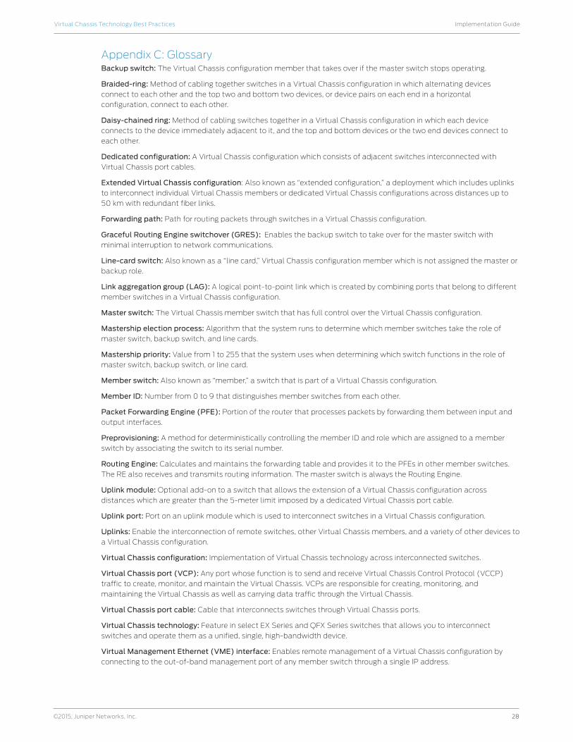
28
Implementation GuideVirtual Chassis Technology Best Practices
©2015, Juniper Networks, Inc.
Appendix C: GlossaryBackup switch: The Virtual Chassis configuration member that takes over if the master switch stops operating.
Braided-ring: Method of cabling together switches in a Virtual Chassis configuration in which alternating devices
connect to each other and the top two and bottom two devices, or device pairs on each end in a horizontal
configuration, connect to each other.
Daisy-chained ring: Method of cabling switches together in a Virtual Chassis configuration in which each device
connects to the device immediately adjacent to it, and the top and bottom devices or the two end devices connect to
each other.
Dedicated configuration: A Virtual Chassis configuration which consists of adjacent switches interconnected with
Virtual Chassis port cables.
Extended Virtual Chassis configuration: Also known as “extended configuration,” a deployment which includes uplinks
to interconnect individual Virtual Chassis members or dedicated Virtual Chassis configurations across distances up to
50 km with redundant fiber links.
Forwarding path: Path for routing packets through switches in a Virtual Chassis configuration.
Graceful Routing Engine switchover (GRES): Enables the backup switch to take over for the master switch with
minimal interruption to network communications.
Line-card switch: Also known as a “line card,” Virtual Chassis configuration member which is not assigned the master or
backup role.
Link aggregation group (LAG): A logical point-to-point link which is created by combining ports that belong to different
member switches in a Virtual Chassis configuration.
Master switch: The Virtual Chassis member switch that has full control over the Virtual Chassis configuration.
Mastership election process: Algorithm that the system runs to determine which member switches take the role of
master switch, backup switch, and line cards.
Mastership priority: Value from 1 to 255 that the system uses when determining which switch functions in the role of
master switch, backup switch, or line card.
Member switch: Also known as “member,” a switch that is part of a Virtual Chassis configuration.
Member ID: Number from 0 to 9 that distinguishes member switches from each other.
Packet Forwarding Engine (PFE): Portion of the router that processes packets by forwarding them between input and
output interfaces.
Preprovisioning: A method for deterministically controlling the member ID and role which are assigned to a member
switch by associating the switch to its serial number.
Routing Engine: Calculates and maintains the forwarding table and provides it to the PFEs in other member switches.
The RE also receives and transmits routing information. The master switch is always the Routing Engine.
Uplink module: Optional add-on to a switch that allows the extension of a Virtual Chassis configuration across
distances which are greater than the 5-meter limit imposed by a dedicated Virtual Chassis port cable.
Uplink port: Port on an uplink module which is used to interconnect switches in a Virtual Chassis configuration.
Uplinks: Enable the interconnection of remote switches, other Virtual Chassis members, and a variety of other devices to
a Virtual Chassis configuration.
Virtual Chassis configuration: Implementation of Virtual Chassis technology across interconnected switches.
Virtual Chassis port (VCP): Any port whose function is to send and receive Virtual Chassis Control Protocol (VCCP)
traffic to create, monitor, and maintain the Virtual Chassis. VCPs are responsible for creating, monitoring, and
maintaining the Virtual Chassis as well as carrying data traffic through the Virtual Chassis.
Virtual Chassis port cable: Cable that interconnects switches through Virtual Chassis ports.
Virtual Chassis technology: Feature in select EX Series and QFX Series switches that allows you to interconnect
switches and operate them as a unified, single, high-bandwidth device.
Virtual Management Ethernet (VME) interface: Enables remote management of a Virtual Chassis configuration by
connecting to the out-of-band management port of any member switch through a single IP address.
Corporate and Sales Headquarters
Juniper Networks, Inc.
1133 Innovation Way
Sunnyvale, CA 94089 USA
Phone: 888.JUNIPER (888.586.4737)
or +1.408.745.2000
Fax: +1.408.745.2100
www.juniper.net
Copyright 2016 Juniper Networks, Inc. All rights reserved. Juniper Networks, the Juniper Networks logo, Junos
and QFabric are registered trademarks of Juniper Networks, Inc. in the United States and other countries.
All other trademarks, service marks, registered marks, or registered service marks are the property of their
respective owners. Juniper Networks assumes no responsibility for any inaccuracies in this document. Juniper
Networks reserves the right to change, modify, transfer, or otherwise revise this publication without notice.
APAC and EMEA Headquarters
Juniper Networks International B.V.
Boeing Avenue 240
1119 PZ Schiphol-Rijk
Amsterdam, The Netherlands
Phone: +31.0.207.125.700
Fax: +31.0.207.125.701
Implementation GuideVirtual Chassis Technology Best Practices
8010018-009-EN Jan 2016
About Juniper NetworksJuniper Networks is in the business of network innovation. From devices to data centers, from consumers to cloud
providers, Juniper Networks delivers the software, silicon and systems that transform the experience and economics
of networking. The company serves customers and partners worldwide. Additional information can be found at
www.juniper.net.