Embed Size (px)
Citation preview
VirtualBiomechanics
Research Report
Biomechanics Research Group, Inc.
The genesis of theLifeMOD®
BiomechanicsModeler
INTRODUCTION Virtual prototypes, in the form of mechanical simulation computer models, have been used by many researchers,
clinical professionals and commercial companies, to study human movement and to develop products used by,
on, for and in humans. The Biomechanics Research Group Inc., in collaboration with several major orthopedic
companies, sports equipment manufacturers, clinical laboratories and research institutions, has developed
computer tools based on the popular ADAMS (MSC.software inc.) software product. This collaboration has
resulted in the powerful biomechanics simulation environment, the LifeMOD Biomechanics Modeler.
As this report documents a sample of the wide variety of commercial projects which served to develop the
technical foundation of LifeMOD. Developed this broad base of application, LifeMOD is capable of generating
human models with a level of sophistication ranging from simple to very complex addressing a wide range of
applications from sports performance to injury evaluation, from gait simulation to vehicle ride comfort.
For more information about the use of the LifeMOD Biomechanics Modeler, please contact Shawn McGuan,
Biomechanics Research Group Inc., 2730 Camino Capistrano, Suite 7, San Clemente, California, USA 92672
Phone: (949) 366-6829 . E-mail: [email protected]
3
HUMAN MOTION SIMULATION
AIDS REHABILITATION RESEARCH
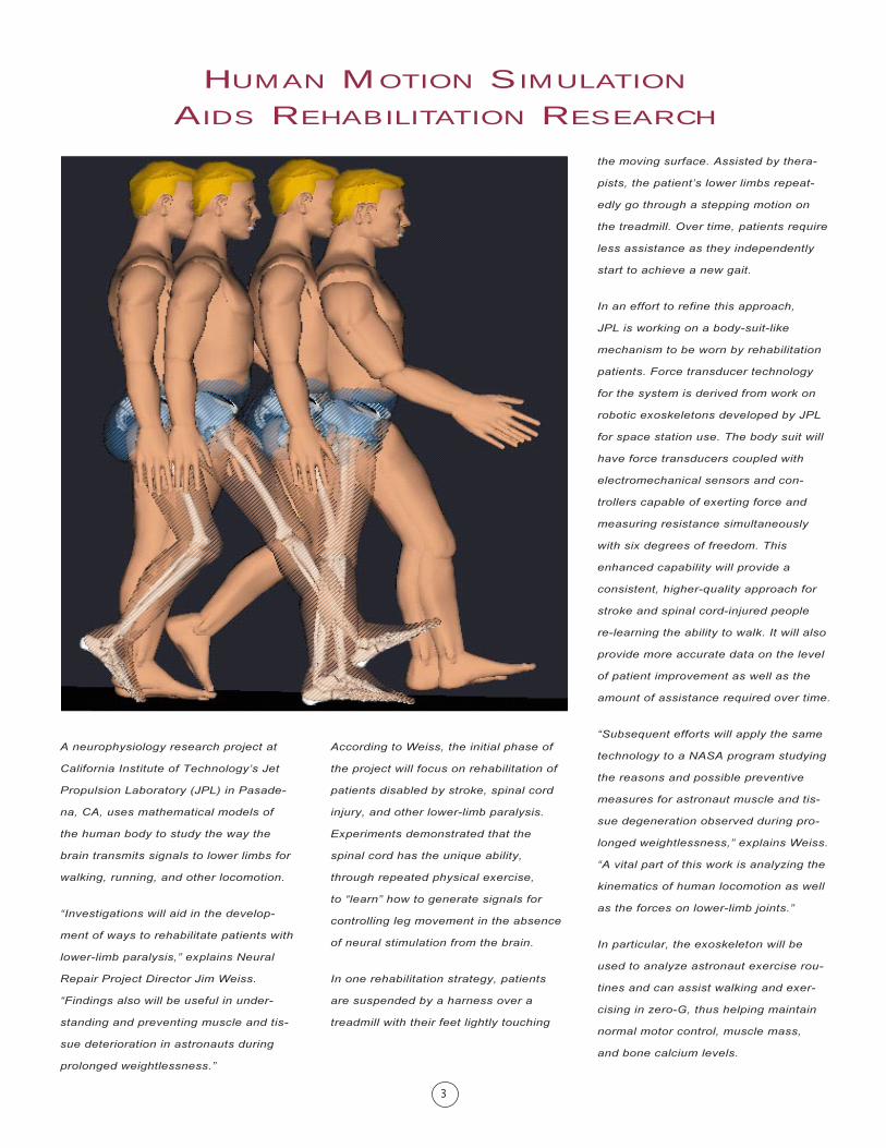
the moving surface. Assisted by thera-
pists, the patient�s lower limbs repeat-
edly go through a stepping motion on
the treadmill. Over time, patients require
less assistance as they independently
start to achieve a new gait.
In an effort to refine this approach,
JPL is working on a body-suit-like
mechanism to be worn by rehabilitation
patients. Force transducer technology
for the system is derived from work on
robotic exoskeletons developed by JPL
for space station use. The body suit will
have force transducers coupled with
electromechanical sensors and con-
trollers capable of exerting force and
measuring resistance simultaneously
with six degrees of freedom. This
enhanced capability will provide a
consistent, higher-quality approach for
stroke and spinal cord-injured people
re-learning the ability to walk. It will also
provide more accurate data on the level
of patient improvement as well as the
amount of assistance required over time.
�Subsequent efforts will apply the same
technology to a NASA program studying
the reasons and possible preventive
measures for astronaut muscle and tis-
sue degeneration observed during pro-
longed weightlessness,� explains Weiss.
�A vital part of this work is analyzing the
kinematics of human locomotion as well
as the forces on lower-limb joints.�
In particular, the exoskeleton will be
used to analyze astronaut exercise rou-
tines and can assist walking and exer-
cising in zero-G, thus helping maintain
normal motor control, muscle mass,
and bone calcium levels.
According to Weiss, the initial phase of
the project will focus on rehabilitation of
patients disabled by stroke, spinal cord
injury, and other lower-limb paralysis.
Experiments demonstrated that the
spinal cord has the unique ability,
through repeated physical exercise,
to �learn� how to generate signals for
controlling leg movement in the absence
of neural stimulation from the brain.
In one rehabilitation strategy, patients
are suspended by a harness over a
treadmill with their feet lightly touching
A neurophysiology research project at
California Institute of Technology�s Jet
Propulsion Laboratory (JPL) in Pasade-
na, CA, uses mathematical models of
the human body to study the way the
brain transmits signals to lower limbs for
walking, running, and other locomotion.
�Investigations will aid in the develop-
ment of ways to rehabilitate patients with
lower-limb paralysis,� explains Neural
Repair Project Director Jim Weiss.
�Findings also will be useful in under-
standing and preventing muscle and tis-
sue deterioration in astronauts during
prolonged weightlessness.�
4
feedback pathway) may be explored on
the model before they are attempted on
the patient. This model will allow scien-
tists to understand the many interrela-
tions between the musculoskeletal and
neural variables, thereby accelerating
treatment innovation and effectiveness.
The controlled locomotion model will
also provide utility for understanding
locomotor compensation strategies in
micro-gravity. Altering the gravity in the
model involves the simple act of altering
the gravity constant parameter (g). With
the gravity environment changed, the
model will adapt to maintain stable loco-
motion and establish comfortable ground
reaction force dissipation potential
throughout the joints of the human
model. Using this model, we can then
determine how the nervous system will
adapt to this change, and can input spe-
cific locomotor strategies for micro-gravi-
ty to test for their effectiveness.
In addition to this practical utility, the
model of the controlled human for loco-
motion will be combined (merged) with a
mechanical simulation model of the
robotic exoskeleton for a complete virtu-
al prototype of the human-in-the-loop
system. This virtual prototype will be
developed in order to design the
mechanics and controller of the
exoskeleton. Using this virtual prototype
method, the geometry, actuators, and
controller function will be designed
before hard prototypes are completed,
thereby accelerating the design process.
�These modeling efforts represent a sig-
nificant step forward in lower extremity
neuromuscular modeling,� says Weiss.
�ADAMS was selected for the project
because of its well-established lower
extremity modeling capabilities.� ■
For this neurophysiology project,
researchers from JPL, the UCLA Brain
Research Institute, and Mechanical
Dynamics are collaborating to develop
the simulation needed to analyze and
predict human motion.
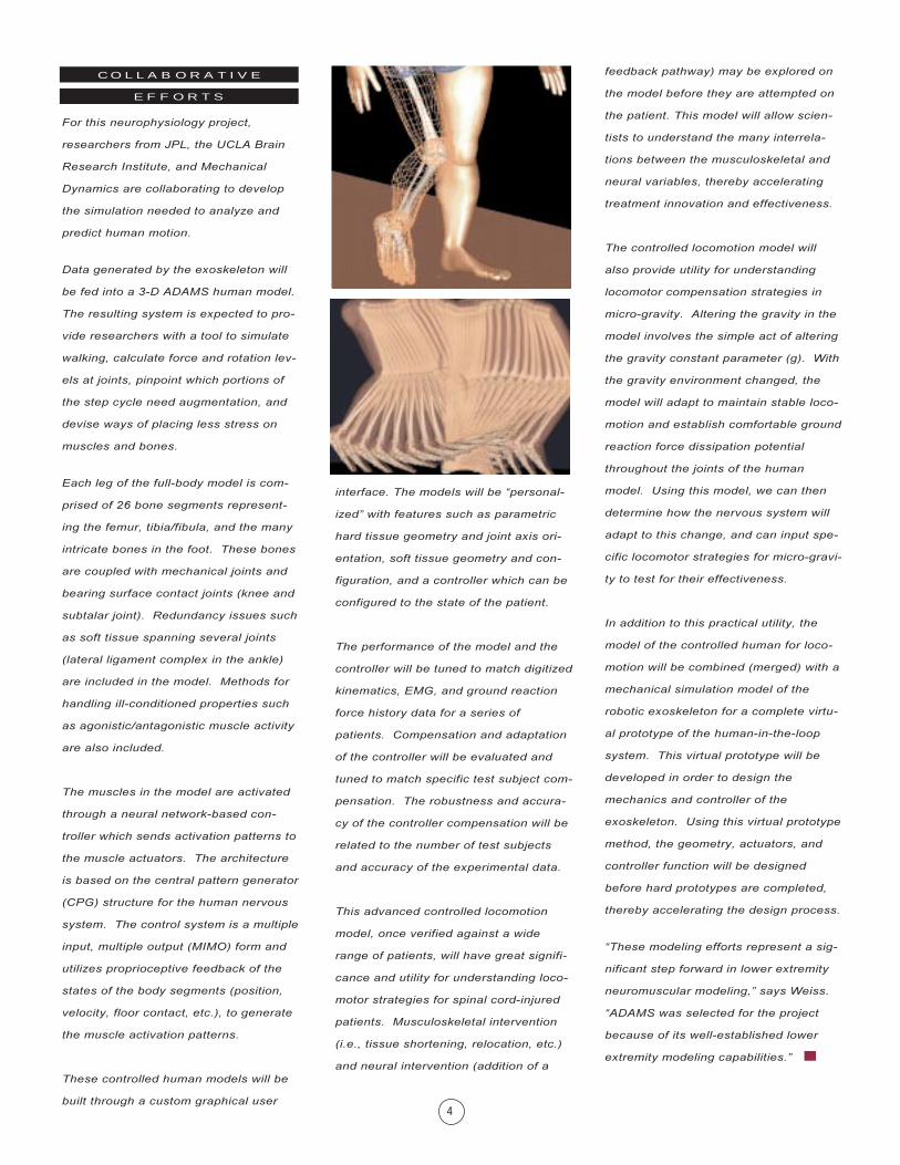
Data generated by the exoskeleton will
be fed into a 3-D ADAMS human model.
The resulting system is expected to pro-
vide researchers with a tool to simulate
walking, calculate force and rotation lev-
els at joints, pinpoint which portions of
the step cycle need augmentation, and
devise ways of placing less stress on
muscles and bones.
Each leg of the full-body model is com-
prised of 26 bone segments represent-
ing the femur, tibia/fibula, and the many
intricate bones in the foot. These bones
are coupled with mechanical joints and
bearing surface contact joints (knee and
subtalar joint). Redundancy issues such
as soft tissue spanning several joints
(lateral ligament complex in the ankle)
are included in the model. Methods for
handling ill-conditioned properties such
as agonistic/antagonistic muscle activity
are also included.
The muscles in the model are activated
through a neural network-based con-
troller which sends activation patterns to
the muscle actuators. The architecture
is based on the central pattern generator
(CPG) structure for the human nervous
system. The control system is a multiple
input, multiple output (MIMO) form and
utilizes proprioceptive feedback of the
states of the body segments (position,
velocity, floor contact, etc.), to generate
the muscle activation patterns.
These controlled human models will be
built through a custom graphical user
interface. The models will be �personal-
ized� with features such as parametric
hard tissue geometry and joint axis ori-
entation, soft tissue geometry and con-
figuration, and a controller which can be
configured to the state of the patient.
The performance of the model and the
controller will be tuned to match digitized
kinematics, EMG, and ground reaction
force history data for a series of
patients. Compensation and adaptation
of the controller will be evaluated and
tuned to match specific test subject com-
pensation. The robustness and accura-
cy of the controller compensation will be
related to the number of test subjects
and accuracy of the experimental data.
This advanced controlled locomotion
model, once verified against a wide
range of patients, will have great signifi-
cance and utility for understanding loco-
motor strategies for spinal cord-injured
patients. Musculoskeletal intervention
(i.e., tissue shortening, relocation, etc.)
and neural intervention (addition of a
C O L L A B O R A T I V E
E F F O R T S
5
tion during rehabilitation for those with
disabilities, such as cerebral palsy,
stroke, and head injuries.
Konantz became so interested in
orthotics that he trained as pedorthist �
a professional who designs and manu-
factures corrective footwear prescribed
by a physician. Konantz quickly saw
limitations in the way in which inserts
are sized and positioned.
�I soon realized that orthotic design was
more of a craft based on experience and
on trial and error than a science,� he
said, �so I set out to find a way of using
computers to quantify and simulate a
patient�s movement.�
After founding Prothotics, Konantz
selected mechanical simulation software
to put orthotic design on a more
scientific basis. One software firm
he approached to write a program for the
new company was Mechanical Dynam-
ics, Inc. Shawn McGuan, a biomechani-
cal research scientist at Mechanical
Dynamics, worked closely with Konantz
Therapists and technicians have tradi-
tionally corrected their patients� foot or
ankle abnormalities by recommending
an orthotic insert, which is worn for sev-
eral weeks, then adjusted incrementally
until the pain is eliminated or at least
reduced to a tolerable level. However, it
can take months before any results are
observed. Moreover, the orthotic inserts
sometimes merely displace stress to
other bones and joints so that other
problems surface years later. A patient
with foot pain might be helped for a few
years, for example, only to develop knee
problems later.
�There are just too many variables to
consider,� said Brent Konantz, president
of Prothotics Corp. in Winnipeg, Manito-
ba. �A patient going to 20 different clin-
ics will get 20 different orthotic devices
to correct the same problem.�
Konantz knows from personal experi-
ence. In 1983, a ruptured Achilles ten-
don ended his career as a sprinter for
provincial and national running teams
in Canada. In working with a team of
health-care professionals during rehabil-
itation, Konantz was fascinated by the
way they corrected pressure on lower-
limb bones and joints through the use
of orthotics, which change the angle
the foot hits the ground during walking
and running.
By raising or lowering the various areas
of the feet, orthotic inserts ease the pain
experienced by patients with sports
injuries as well as foot and ankle anom-
alies related to arthritis, diabetes, and
other debilitating diseases. Orthotics
also help promote proper muscle func-
to customize ADAMS for orthotic design
applications.
The resulting package simulates a
patient�s walking and running gait based
on leg and ankle measurements. Based
on these simulations, clinicians can
immediately visualize the effects of
various orthotic insert designs to find
the best one for each patient without
going through the time and expense of
making and trying one after another
until pain subsides.
�This approach has the potential to
revolutionize the way we treat lower-
limb pain, disability, and rehabilitation,�
Konantz said. �We�ve already used the
software to help hundreds of patients,
and have plans to expand operations to
clinics in other cities. This is possible
because of our ability to simulate biome-
chanical systems with ADAMS, and the
expertise and willingness of Mechanical
Dynamics staff to customize their soft-
ware for our application.�
�If ADAMS can simulate the moving
parts of a mechanical product,� Konantz
added, �then why not people�s feet,
ankles, hips, and knees?�
McGuan worked with Konantz to develop
an interface that enables an orthotic
clinician with little or no computer train-
ing to enter patient data and interpret
results easily. Specifications compiled
by Konantz for the project included
parameters defining the movement for
�medical normal� limb functions gath-
ered from interviews with doctors and
measurements of human anatomy. Also
included are results of cooperative
research with Nike and other footwear
manufacturers.
OPTIMIZING ORTHOTIC DESIGNS
THROUGH VIRTUAL GAIT SIMULATION
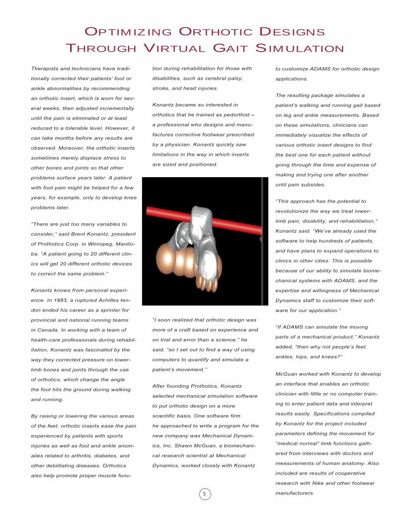
The human locomotion model developed
for Prothotics is based on the Shock dis-
sipation lower extremity model McGuan
developed for Nike, used in the develop-
ment of stable sport shoes. The model
produces a biomechanc �map� of how
the lower extremity dissipates the
ground reaction force. The map shows
the effect of the ground reaction force at
the foot and traces up through the ankle,
knee, hip, and lower back. Research
has shown that this dissipation profile
should be smooth and continuous, since
any sharp spikes could represent acute
stress sites. Considering how many
thousands of steps the average person
takes per day, any abnormality in the
shock dissipation capability of the lower
extremity could translate to chronic pain
and degenerative injuries.
The software system developed around
this human locomotion model uses
patient information gathered by the clini-
cian as initial input. This input includes
age, gender, weight, and measurements
including the alignment of several effec-
tive articulation axes in the foot, as well
as the range-of-motion about each axes.
From these measurements, a �personal-
ized� model is built.
On the basis of this information, the soft-
ware simulates the gait of the patient and
compares that replication with the nor-
mal gait as determined by the computer
for a numerically average individual of
similar age, weight, and proportions. The
software iterates on the geometry under
the foot necessary to normalize the
ground reaction force dissipation signa-
ture in the patient�s lower extremity. The
resultant geometric contour represents
the geometry of the proposed orthoses.
�Basically, the computer shows the clini-
cian how the patient is walking, how he
or she is supposed to be walking, and
what can be done to get the walking
equivalent to what is considered normal,�
Konantz said.
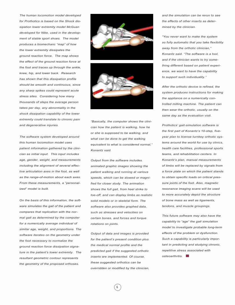
Output from the software includes
animated graphic images showing the
patient walking and running at various
speeds, which can be slowed or magni-
fied for closer study. The animation
shows the full gait, from heel strike to
toe-off, and can display limbs as realistic
solid models or in skeletal form. The
software also provides graphed data,
such as stresses and velocities on
certain bones, and forces and torque
rotations on joints.
Output of data and images is provided
for the patient�s present condition plus
the medical normal profile and the
predicted gait if the suggested orthotic
inserts are implemented. Of course,
these suggested orthotics can be
overridden or modified by the clinician,
and the simulation can be rerun to see
the effects of other inserts as deter-
mined by the clinician.
�You never want to make the system
so fully automatic that you take flexibility
away from the orthotic clinician,�
Konantz said. �The software is a tool,
and if the clinician wants to try some-
thing different based on patient experi-
ence, we want to have the capability
to support such individuality.�
After the orthotic device is refined, the
system produces instructions for making
the appliance on a numerically con-
trolled milling machine. The patient can
then wear the orthotic, usually on the
same day as the evaluation visit.
Prothotics� gait-simulation software is
the first part of Konantz�s 10-step, five-
year plan to license turnkey orthotic sys-
tems around the world for use by clinics,
health care facilities, professional sports
teams, and rehabilitation centers. In
Konantz�s plan, manual measurements
of limbs will be replaced by signals from
a force plate on which the patient stands
to obtain specific loads on critical pres-
sure joints of the foot. Also, magnetic
resonance imaging scans will be used
to more accurately depict the structure
of bone mass as well as ligaments,
tendons, and muscle groupings.
This future software may also have the
capability to �age� the gait simulation
model to investigate probable long-term
effects of the problem or dysfunction.
Such a capability is particularly impor-
tant in predicting and studying chronic,
repetitive stress associated with
osteoarthritis. ■
6
7
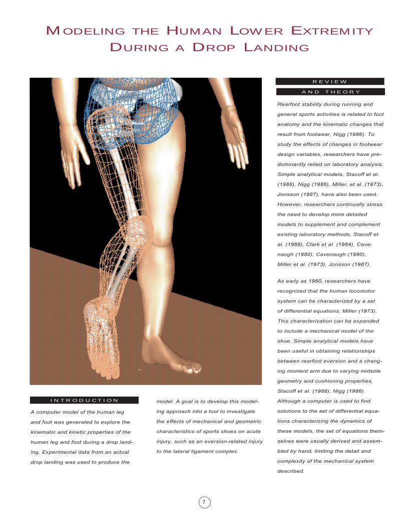
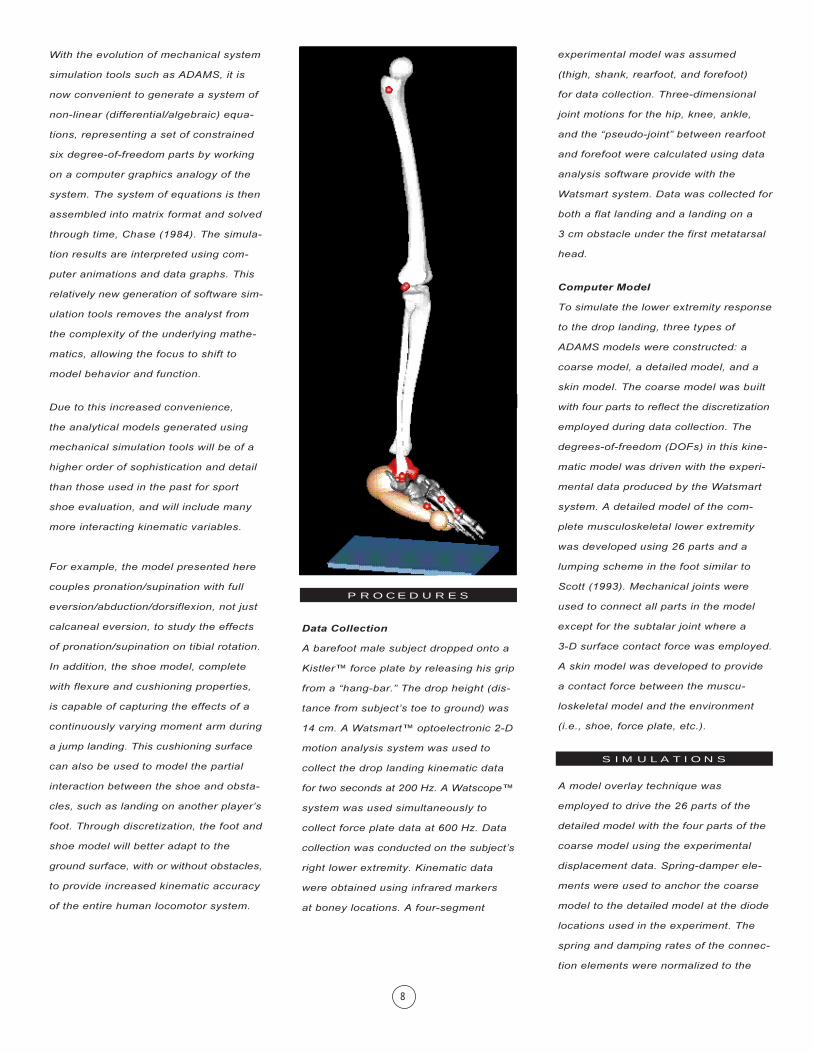
A computer model of the human leg
and foot was generated to explore the
kinematic and kinetic properties of the
human leg and foot during a drop land-
ing. Experimental data from an actual
drop landing was used to produce the
model. A goal is to develop this model-
ing approach into a tool to investigate
the effects of mechanical and geometric
characteristics of sports shoes on acute
injury, such as an eversion-related injury
to the lateral ligament complex.
Rearfoot stability during running and
general sports activities is related to foot
anatomy and the kinematic changes that
result from footwear, Nigg (1986). To
study the effects of changes in footwear
design variables, researchers have pre-
dominantly relied on laboratory analysis.
Simple analytical models, Stacoff et al.
(1988), Nigg (1986), Miller, et al. (1973),
Jonsson (1987), have also been used.
However, researchers continually stress
the need to develop more detailed
models to supplement and complement
existing laboratory methods, Stacoff et
al. (1988), Clark et al. (1984), Cave-
naugh (1980), Cavenaugh (1990),
Miller et al. (1973), Jonsson (1987).
As early as 1960, researchers have
recognized that the human locomotor
system can be characterized by a set
of differential equations, Miller (1973).
This characterization can be expanded
to include a mechanical model of the
shoe. Simple analytical models have
been useful in obtaining relationships
between rearfoot eversion and a chang-
ing moment arm due to varying midsole
geometry and cushioning properties,
Stacoff et al. (1988), Nigg (1986).
Although a computer is used to find
solutions to the set of differential equa-
tions characterizing the dynamics of
these models, the set of equations them-
selves were usually derived and assem-
bled by hand, limiting the detail and
complexity of the mechanical system
described.
MODELING THE HUMAN LOWER EXTREMITY
DURING A DROP LANDING
R E V I E W
A N D T H E O R Y
I N T R O D U C T I O N
A N D T H E O R Y
R E V I E W
With the evolution of mechanical system
simulation tools such as ADAMS, it is
now convenient to generate a system of
non-linear (differential/algebraic) equa-
tions, representing a set of constrained
six degree-of-freedom parts by working
on a computer graphics analogy of the
system. The system of equations is then
assembled into matrix format and solved
through time, Chase (1984). The simula-
tion results are interpreted using com-
puter animations and data graphs. This
relatively new generation of software sim-
ulation tools removes the analyst from
the complexity of the underlying mathe-
matics, allowing the focus to shift to
model behavior and function.
Due to this increased convenience,
the analytical models generated using
mechanical simulation tools will be of a
higher order of sophistication and detail
than those used in the past for sport
shoe evaluation, and will include many
more interacting kinematic variables.
For example, the model presented here
couples pronation/supination with full
eversion/abduction/dorsiflexion, not just
calcaneal eversion, to study the effects
of pronation/supination on tibial rotation.
In addition, the shoe model, complete
with flexure and cushioning properties,
is capable of capturing the effects of a
continuously varying moment arm during
a jump landing. This cushioning surface
can also be used to model the partial
interaction between the shoe and obsta-
cles, such as landing on another player�s
foot. Through discretization, the foot and
shoe model will better adapt to the
ground surface, with or without obstacles,
to provide increased kinematic accuracy
of the entire human locomotor system.
experimental model was assumed
(thigh, shank, rearfoot, and forefoot)
for data collection. Three-dimensional
joint motions for the hip, knee, ankle,
and the �pseudo-joint� between rearfoot
and forefoot were calculated using data
analysis software provide with the
Watsmart system. Data was collected for
both a flat landing and a landing on a
3 cm obstacle under the first metatarsal
head.
Computer Model
To simulate the lower extremity response
to the drop landing, three types of
ADAMS models were constructed: a
coarse model, a detailed model, and a
skin model. The coarse model was built
with four parts to reflect the discretization
employed during data collection. The
degrees-of-freedom (DOFs) in this kine-
matic model was driven with the experi-
mental data produced by the Watsmart
system. A detailed model of the com-
plete musculoskeletal lower extremity
was developed using 26 parts and a
lumping scheme in the foot similar to
Scott (1993). Mechanical joints were
used to connect all parts in the model
except for the subtalar joint where a
3-D surface contact force was employed.
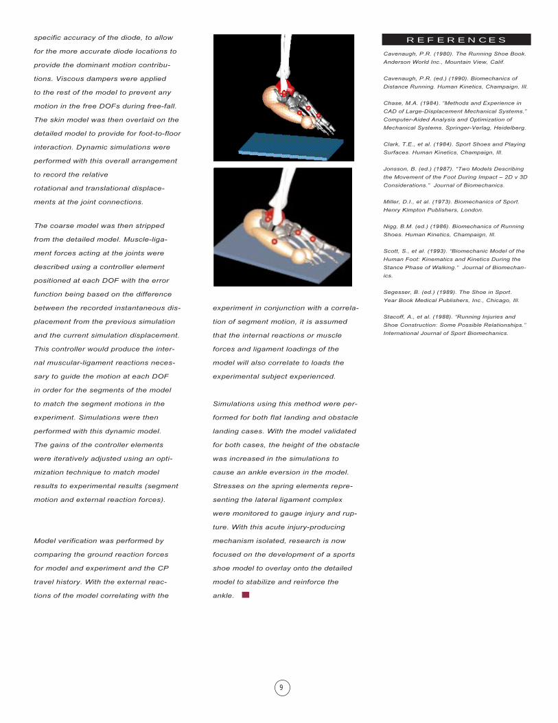
A skin model was developed to provide
a contact force between the muscu-
loskeletal model and the environment
(i.e., shoe, force plate, etc.).
A model overlay technique was
employed to drive the 26 parts of the
detailed model with the four parts of the
coarse model using the experimental
displacement data. Spring-damper ele-
ments were used to anchor the coarse
model to the detailed model at the diode
locations used in the experiment. The
spring and damping rates of the connec-
tion elements were normalized to the
P R O C E D U R E S
Data Collection
A barefoot male subject dropped onto a
Kistler� force plate by releasing his grip
from a �hang-bar.� The drop height (dis-
tance from subject�s toe to ground) was
14 cm. A Watsmart� optoelectronic 2-D
motion analysis system was used to
collect the drop landing kinematic data
for two seconds at 200 Hz. A Watscope�
system was used simultaneously to
collect force plate data at 600 Hz. Data
collection was conducted on the subject�s
right lower extremity. Kinematic data
were obtained using infrared markers
at boney locations. A four-segment
S I M U L A T I O N S
P R O C E D U R E S
8
specific accuracy of the diode, to allow
for the more accurate diode locations to
provide the dominant motion contribu-
tions. Viscous dampers were applied
to the rest of the model to prevent any
motion in the free DOFs during free-fall.
The skin model was then overlaid on the
detailed model to provide for foot-to-floor
interaction. Dynamic simulations were
performed with this overall arrangement
to record the relative
rotational and translational displace-
ments at the joint connections.
The coarse model was then stripped
from the detailed model. Muscle-liga-
ment forces acting at the joints were
described using a controller element
positioned at each DOF with the error
function being based on the difference
between the recorded instantaneous dis-
placement from the previous simulation
and the current simulation displacement.
This controller would produce the inter-
nal muscular-ligament reactions neces-
sary to guide the motion at each DOF
in order for the segments of the model
to match the segment motions in the
experiment. Simulations were then
performed with this dynamic model.
The gains of the controller elements
were iteratively adjusted using an opti-
mization technique to match model
results to experimental results (segment
motion and external reaction forces).
Model verification was performed by
comparing the ground reaction forces
for model and experiment and the CP
travel history. With the external reac-
tions of the model correlating with the
experiment in conjunction with a correla-
tion of segment motion, it is assumed
that the internal reactions or muscle
forces and ligament loadings of the
model will also correlate to loads the
experimental subject experienced.
Simulations using this method were per-
formed for both flat landing and obstacle
landing cases. With the model validated
for both cases, the height of the obstacle
was increased in the simulations to
cause an ankle eversion in the model.
Stresses on the spring elements repre-
senting the lateral ligament complex
were monitored to gauge injury and rup-
ture. With this acute injury-producing
mechanism isolated, research is now
focused on the development of a sports
shoe model to overlay onto the detailed
model to stabilize and reinforce the
ankle. ■
Cavenaugh, P.R. (1980). The Running Shoe Book.
Anderson World Inc., Mountain View, Calif.
Cavenaugh, P.R. (ed.) (1990). Biomechanics of
Distance Running. Human Kinetics, Champaign, Ill.
Chase, M.A. (1984). �Methods and Experience in
CAD of Large-Displacement Mechanical Systems.�
Computer-Aided Analysis and Optimization of
Mechanical Systems. Springer-Verlag, Heidelberg.
Clark, T.E., et al. (1984). Sport Shoes and Playing
Surfaces. Human Kinetics, Champaign, Ill.
Jonsson, B. (ed.) (1987). �Two Models Describing
the Movement of the Foot During Impact � 2D v 3D
Considerations.� Journal of Biomechanics.
Miller, D.I., et al. (1973). Biomechanics of Sport.
Henry Kimpton Publishers, London.
Nigg, B.M. (ed.) (1986). Biomechanics of Running
Shoes. Human Kinetics, Champaign, Ill.
Scott, S., et al. (1993). �Biomechanic Model of the
Human Foot: Kinematics and Kinetics During the
Stance Phase of Walking.� Journal of Biomechan-
ics.
Segesser, B. (ed.) (1989). The Shoe in Sport.
Year Book Medical Publishers, Inc., Chicago, Ill.
Stacoff, A., et al. (1988). �Running Injuries and
Shoe Construction: Some Possible Relationships.�
International Journal of Sport Biomechanics.
R E F E R E N C E S
9
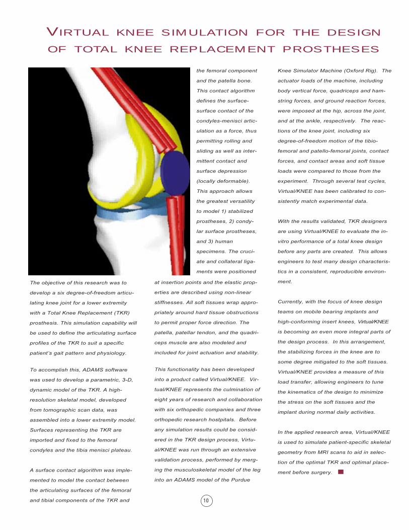
The objective of this research was to
develop a six degree-of-freedom articu-
lating knee joint for a lower extremity
with a Total Knee Replacement (TKR)
prosthesis. This simulation capability will
be used to define the articulating surface
profiles of the TKR to suit a specific
patient�s gait pattern and physiology.
To accomplish this, ADAMS software
was used to develop a parametric, 3-D,
dynamic model of the TKR. A high-
resolution skeletal model, developed
from tomographic scan data, was
assembled into a lower extremity model.
Surfaces representing the TKR are
imported and fixed to the femoral
condyles and the tibia menisci plateau.
A surface contact algorithm was imple-
mented to model the contact between
the articulating surfaces of the femoral
and tibial components of the TKR and
the femoral component
and the patella bone.
This contact algorithm
defines the surface-
surface contact of the
condyles-menisci artic-
ulation as a force, thus
permitting rolling and
sliding as well as inter-
mittent contact and
surface depression
(locally deformable).
This approach allows
the greatest versatility
to model 1) stabilized
prostheses, 2) condy-
lar surface prostheses,
and 3) human
specimens. The cruci-
ate and collateral liga-
ments were positioned
10
VIRTUAL KNEE SIMULATION FOR THE DESIGN
OF TOTAL KNEE REPLACEMENT PROSTHESES
at insertion points and the elastic prop-
erties are described using non-linear
stiffnesses. All soft tissues wrap appro-
priately around hard tissue obstructions
to permit proper force direction. The
patella, patellar tendon, and the quadri-
ceps muscle are also modeled and
included for joint actuation and stability.
This functionality has been developed
into a product called Virtual/KNEE. Vir-
tual/KNEE represents the culmination of
eight years of research and collaboration
with six orthopedic companies and three
orthopedic research hostpitals. Before
any simulation results could be consid-
ered in the TKR design process, Virtu-
al/KNEE was run through an extensive
validation process, performed by merg-
ing the musculoskeletal model of the leg
into an ADAMS model of the Purdue
Knee Simulator Machine (Oxford Rig). The
actuator loads of the machine, including
body vertical force, quadriceps and ham-
string forces, and ground reaction forces,
were imposed at the hip, across the joint,
and at the ankle, respectively. The reac-
tions of the knee joint, including six
degree-of-freedom motion of the tibio-
femoral and patello-femoral joints, contact
forces, and contact areas and soft tissue
loads were compared to those from the
experiment. Through several test cycles,
Virtual/KNEE has been calibrated to con-
sistently match experimental data.
With the results validated, TKR designers
are using Virtual/KNEE to evaluate the in-
vitro performance of a total knee design
before any parts are created. This allows
engineers to test many design characteris-
tics in a consistent, reproducible environ-
ment.
Currently, with the focus of knee design
teams on mobile bearing implants and
high-conforming insert knees, Virtual/KNEE
is becoming an even more integral parts of
the design process. In this arrangement,
the stabilizing forces in the knee are to
some degree mitigated to the soft tissues.
Virtual/KNEE provides a measure of this
load transfer, allowing engineers to tune
the kinematics of the design to minimize
the stress on the soft tissues and the
implant during normal daily activities.
In the applied research area, Virtual/KNEE
is used to simulate patient-specific skeletal
geometry from MRI scans to aid in selec-
tion of the optimal TKR and optimal place-
ment before surgery. ■
INVESTIGATING AN INJURY-PRODUCING
MOTORCYCLE CRASH
I N T R O D U C T I O N
A motorcycle rider must be constantly
attentive to environmental disturbances
� potholes, insects, wind, etc. These
disturbances can cause crashes, and
crashes usually result in injury.
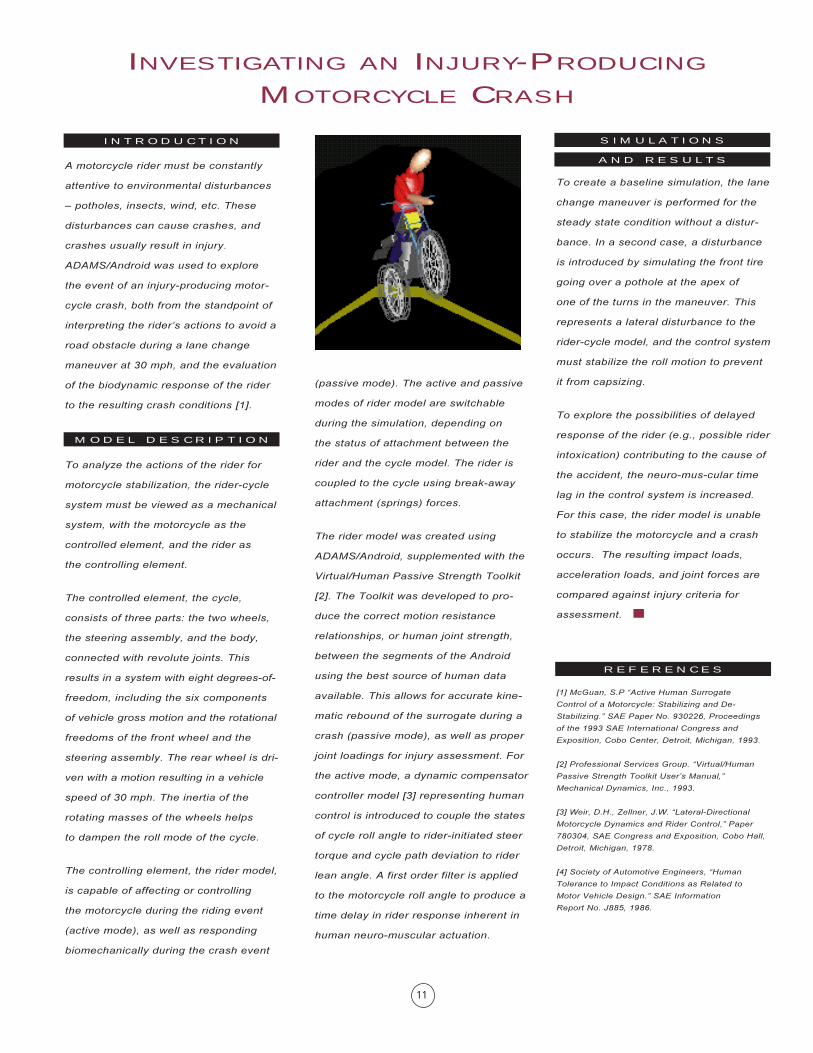
ADAMS/Android was used to explore
the event of an injury-producing motor-
cycle crash, both from the standpoint of
interpreting the rider�s actions to avoid a
road obstacle during a lane change
maneuver at 30 mph, and the evaluation
of the biodynamic response of the rider
to the resulting crash conditions [1].
To analyze the actions of the rider for
motorcycle stabilization, the rider-cycle
system must be viewed as a mechanical
system, with the motorcycle as the
controlled element, and the rider as
the controlling element.
The controlled element, the cycle,
consists of three parts: the two wheels,
the steering assembly, and the body,
connected with revolute joints. This
results in a system with eight degrees-of-
freedom, including the six components
of vehicle gross motion and the rotational
freedoms of the front wheel and the
steering assembly. The rear wheel is dri-
ven with a motion resulting in a vehicle
speed of 30 mph. The inertia of the
rotating masses of the wheels helps
to dampen the roll mode of the cycle.
The controlling element, the rider model,
is capable of affecting or controlling
the motorcycle during the riding event
(active mode), as well as responding
biomechanically during the crash event
(passive mode). The active and passive
modes of rider model are switchable
during the simulation, depending on
the status of attachment between the
rider and the cycle model. The rider is
coupled to the cycle using break-away
attachment (springs) forces.
The rider model was created using
ADAMS/Android, supplemented with the
Virtual/Human Passive Strength Toolkit
[2]. The Toolkit was developed to pro-
duce the correct motion resistance
relationships, or human joint strength,
between the segments of the Android
using the best source of human data
available. This allows for accurate kine-
matic rebound of the surrogate during a
crash (passive mode), as well as proper
joint loadings for injury assessment. For
the active mode, a dynamic compensator
controller model [3] representing human
control is introduced to couple the states
of cycle roll angle to rider-initiated steer
torque and cycle path deviation to rider
lean angle. A first order filter is applied
to the motorcycle roll angle to produce a
time delay in rider response inherent in
human neuro-muscular actuation.
To create a baseline simulation, the lane
change maneuver is performed for the
steady state condition without a distur-
bance. In a second case, a disturbance
is introduced by simulating the front tire
going over a pothole at the apex of
one of the turns in the maneuver. This
represents a lateral disturbance to the
rider-cycle model, and the control system
must stabilize the roll motion to prevent
it from capsizing.
To explore the possibilities of delayed
response of the rider (e.g., possible rider
intoxication) contributing to the cause of
the accident, the neuro-mus-cular time
lag in the control system is increased.
For this case, the rider model is unable
to stabilize the motorcycle and a crash
occurs. The resulting impact loads,
acceleration loads, and joint forces are
compared against injury criteria for
assessment. ■
[1] McGuan, S.P �Active Human Surrogate
Control of a Motorcycle: Stabilizing and De-
Stabilizing.� SAE Paper No. 930226, Proceedings
of the 1993 SAE International Congress and
Exposition, Cobo Center, Detroit, Michigan, 1993.
[2] Professional Services Group. �Virtual/Human
Passive Strength Toolkit User�s Manual,�
Mechanical Dynamics, Inc., 1993.
[3] Weir, D.H., Zellner, J.W. �Lateral-Directional
Motorcycle Dynamics and Rider Control,� Paper
780304, SAE Congress and Exposition, Cobo Hall,
Detroit, Michigan, 1978.
[4] Society of Automotive Engineers, �Human
Tolerance to Impact Conditions as Related to
Motor Vehicle Design.� SAE Information
Report No. J885, 1986.
S I M U L A T I O N S
A N D R E S U L T S
M O D E L D E S C R I P T I O N
R E F E R E N C E S
11

TheVirtual
BiomechanicsCompany
For over 15 years, the scientists of the Biomechanics Research Group, Inc. have been developing complete solutions to commercial and research institutions interested in the physics behind biological motion.
The flagship product, LifeMOD®, is modularized and highly customizable program for general biomechanics modeling and specialized applications including, orthopedics, gait, injury, sports equipment/performance, ergonomics, rehabilitation, etc.
To support this activity, BRG offers comprehensive consulting services and training.
If you would like to explore the applications and benefits of virtual biomechanics within your team, please contact us today.
CorporateHeadquartersBiomechanics Research Group, Inc.2730 Camino Capistrano, Suite 7San Clemente, California 82672 USAPhone: (949) 366-6829E-mail: [email protected]
www.lifemodeler.com
© 2002, Biomechanics Research Group, Inc. All rights reserved. LifeMOD and the Biomechanics Research Group logo are registerd trademarks.