Embed Size (px)
Citation preview
F20470I EN (082012)
Viking Installation Guide
Professional & Outdoor Hoods
Viking Range Corporation
111 Front Street
Greenwood, Mississippi 38930 USA
(662) 455-1200
For product information,
call 1-888-VIKING1 (845-4641)
or visit the Viking Web site at
vikingrange.com

Table of Contents
3
IMPORTANT–Please Read and Follow!NOTE: If installing hood with warming shelf panel,install warming shelf panel first.
IMPORTANT – PLEASE READ AND FOLLOW• Before beginning, please read these instructions
completely and carefully.• Do not remove permanently affixed labels, warnings, or
plates from the product. This may void the warranty.• Please observe all local and national codes and
ordinances. If no local codes are applicable, wire inaccordance with the National Electrical Code,ANSI/NFPA 70-latest edition.
• Damp environment approved models should be installedin a covered non-enclosed area and should be protectedfrom the elements as much as possible.
• The installer should leave these instructions with theconsumer who should retain for local inspector’s use andfor future reference.
• Check with a qualified and trained installer or local codesfor makeup air requirement, if any.
This hood is for residential installation only and is notdesigned for installation over a commercial product. Makesure power is off at the main circuit breaker or fuse boxbefore making connections. To avoid risk of fire, electricshock, or injury to persons, turn off the electricity to thehood from the power supply before servicing or cleaning.Viking hoods are equipped with variable speed controlblowers. These units will not function with a single speedventilator. All Viking Range ventilator kits are designedspecifically for use with Viking Range hoods. Use of anynon-Viking Range ventilator kit will void the hood warranty.
Viking hoods are equipped with the variable speedcontrols for blowers. These units will not function with asingle speed ventilator. All Viking ventilator kits aredesigned specifically for use with Viking hoods. Use of anynon-Viking ventilator kit will void the hood warranty.
READ AND SAVE THESE INSTRUCTIONS
TO REDUCE THE RISK OF FIRE, ELECTRICALSHOCK, OR INJURY TO PERSONS, OBSERVETHE FOLLOWING:1. Installation work and electrical wiring must be
done by qualified person(s) in accordance withall applicable codes and standards, includingfire-rated construction.
2. Sufficient air is needed for proper combustionand exhausting of gases through the flute(chimney) of fuel burning equipment to preventback drafting. Follow the heating equipmentmanufacturer’s guideline and safety standardssuch as those published by the National FireProtection Association (NFPA), and theAmerican Society for Heating, Refrigeration andAir Conditioning Engineers (ASHRAE), and thelocal code authorities.
3. When cutting of drilling into wall or ceiling, donot damage electrical wiring and other hiddenutilities.
4. Ducted fans must always be vented to the outdoors.5. WARNING!: To reduce risk of fire, use only
metal ductwork6. CAUTION!: To reduce risk of fire and to
properly exhaust air, be sure to duct air outside.Do not vent exhaust air into spaces within wallsor ceilings, or into attics, crawl spaces, orgarages.
7. CAUTION!: To Reduce the Risk of Fire andElectric Shock, Install this rangehood only withremote blower models manufactured by Viking,model numbers – DEV900/DEV1200,VEV900/VEV1200, OR DEV1500, VEV1500 orintegral blowers manufactured by Viking, modelnumbers – DIV300, DIV440, DIV600, DIV800,DIV1200, VIV300, VIV600, or VIV1200. NOTE –Please refer inside for specific canopy/blowercombinations.
W A R N I N G
W A R N I N GTo reduce the risk of fire, electric shock, or injuryto persons, observe the following:
• Use this unit only in the manner intended by themanufacturer. If you have any questions, contactthe manufacturer.
• Before servicing or cleaning unit, switch power offat service panel and lock service panel to preventpower from being switched on accidentally. Whenthe service disconnecting means cannot be locked,securely fasten a prominent warning device, suchas a tag, to the service panel.
2
Warnings & Important Information_ _ _ _ _ _ _ _ _ _ _ _ _ _ _ _ _ _ _ _ _ _ _ _ _ _ _ _ _ _ _ _ _ _ _ _ _ _ _ _ _ _ _ _ _ _ _ _ _ _ _ _ _ _ _ _ 3-4VWH 10”H. Wall Hoods w/Standard Ventilator 24”, 30”, & 36”
Dimensions & Specifications _ _ _ _ _ _ _ _ _ _ _ _ _ _ _ _ _ _ _ _ _ _ _ _ _ _ _ _ _ _ _ _ _ _ _ _ _ _ _ _ _ _ _ _ _ _ _ _ _ _ _ _ _ 5Clearance Dimensions _ _ _ _ _ _ _ _ _ _ _ _ _ _ _ _ _ _ _ _ _ _ _ _ _ _ _ _ _ _ _ _ _ _ _ _ _ _ _ _ _ _ _ _ _ _ _ _ _ _ _ _ _ _ _ _ _ _ _ 6Interior Ventilator Dimensions _ _ _ _ _ _ _ _ _ _ _ _ _ _ _ _ _ _ _ _ _ _ _ _ _ _ _ _ _ _ _ _ _ _ _ _ _ _ _ _ _ _ _ _ _ _ _ _ _ _ _ _ 7
VWH 18”H. 24”/27” Deep Wall Hoods 30”, 36”, 42”, 48”, 54”, & 60”Dimensions & Specifications _ _ _ _ _ _ _ _ _ _ _ _ _ _ _ _ _ _ _ _ _ _ _ _ _ _ _ _ _ _ _ _ _ _ _ _ _ _ _ _ _ _ _ _ _ _ _ _ _ _ _ _ _ _ 8Clearance Dimensions _ _ _ _ _ _ _ _ _ _ _ _ _ _ _ _ _ _ _ _ _ _ _ _ _ _ _ _ _ _ _ _ _ _ _ _ _ _ _ _ _ _ _ _ _ _ _ _ _ _ _ _ _ _ _ _ _ _ _ _ _ 9Interior Ventilator Dimensions _ _ _ _ _ _ _ _ _ _ _ _ _ _ _ _ _ _ _ _ _ _ _ _ _ _ _ _ _ _ _ _ _ _ _ _ _ _ _ _ _ _ _ _ _ _ _ _ _ _ _ _ _ 10Exterior Ventilator Dimensions _ _ _ _ _ _ _ _ _ _ _ _ _ _ _ _ _ _ _ _ _ _ _ _ _ _ _ _ _ _ _ _ _ _ _ _ _ _ _ _ _ _ _ _ _ _ _ _ _ _ _ 11
VWHO 18”H. Outdoor Wall Hoods 36”, 48”, & 60”Dimensions & Specifications _ _ _ _ _ _ _ _ _ _ _ _ _ _ _ _ _ _ _ _ _ _ _ _ _ _ _ _ _ _ _ _ _ _ _ _ _ _ _ _ _ _ _ _ _ _ _ _ _ _ _ _ _ 12Clearance Dimensions _ _ _ _ _ _ _ _ _ _ _ _ _ _ _ _ _ _ _ _ _ _ _ _ _ _ _ _ _ _ _ _ _ _ _ _ _ _ _ _ _ _ _ _ _ _ _ _ _ _ _ _ _ _ _ _ _ _ 13
VCWH Chimney Wall Hoods 30”, 36”, 42”, 48”, 54”, 60”, & 66”Dimensions & Specifications _ _ _ _ _ _ _ _ _ _ _ _ _ _ _ _ _ _ _ _ _ _ _ _ _ _ _ _ _ _ _ _ _ _ _ _ _ _ _ _ _ _ _ _ _ _ _ _ _ _ _ _ _ 14Clearance Dimensions _ _ _ _ _ _ _ _ _ _ _ _ _ _ _ _ _ _ _ _ _ _ _ _ _ _ _ _ _ _ _ _ _ _ _ _ _ _ _ _ _ _ _ _ _ _ _ _ _ _ _ _ _ _ _ _ _ _ 15Interior Ventilator Dimensions _ _ _ _ _ _ _ _ _ _ _ _ _ _ _ _ _ _ _ _ _ _ _ _ _ _ _ _ _ _ _ _ _ _ _ _ _ _ _ _ _ _ _ _ _ _ _ _ _ _ _ 16Exterior Ventilator Dimensions _ _ _ _ _ _ _ _ _ _ _ _ _ _ _ _ _ _ _ _ _ _ _ _ _ _ _ _ _ _ _ _ _ _ _ _ _ _ _ _ _ _ _ _ _ _ _ _ _ _ _ 17
DCWH Classic Chimney Hoods 30”, 36”, 42”, & 48”Dimensions & Specifications _ _ _ _ _ _ _ _ _ _ _ _ _ _ _ _ _ _ _ _ _ _ _ _ _ _ _ _ _ _ _ _ _ _ _ _ _ _ _ _ _ _ _ _ _ _ _ _ _ _ _ _ _ 18Clearance Dimensions_ _ _ _ _ _ _ _ _ _ _ _ _ _ _ _ _ _ _ _ _ _ _ _ _ _ _ _ _ _ _ _ _ _ _ _ _ _ _ _ _ _ _ _ _ _ _ _ _ _ _ _ _ _ _ _ _ _ _ 19Interior Ventilator Dimensions _ _ _ _ _ _ _ _ _ _ _ _ _ _ _ _ _ _ _ _ _ _ _ _ _ _ _ _ _ _ _ _ _ _ _ _ _ _ _ _ _ _ _ _ _ _ _ _ _ _ _ 20Exterior Ventilator Dimensions _ _ _ _ _ _ _ _ _ _ _ _ _ _ _ _ _ _ _ _ _ _ _ _ _ _ _ _ _ _ _ _ _ _ _ _ _ _ _ _ _ _ _ _ _ _ _ _ _ _ _ 21
VCIH Chimney Island Hoods 36”, 42”, 54”, & 66”Dimensions & Specifications _ _ _ _ _ _ _ _ _ _ _ _ _ _ _ _ _ _ _ _ _ _ _ _ _ _ _ _ _ _ _ _ _ _ _ _ _ _ _ _ _ _ _ _ _ _ _ _ _ _ _ _ _ 22Clearance Dimensions_ _ _ _ _ _ _ _ _ _ _ _ _ _ _ _ _ _ _ _ _ _ _ _ _ _ _ _ _ _ _ _ _ _ _ _ _ _ _ _ _ _ _ _ _ _ _ _ _ _ _ _ _ _ _ _ _ _ _ 23Interior Ventilator Dimensions _ _ _ _ _ _ _ _ _ _ _ _ _ _ _ _ _ _ _ _ _ _ _ _ _ _ _ _ _ _ _ _ _ _ _ _ _ _ _ _ _ _ _ _ _ _ _ _ _ _ _ 24Exterior Ventilator Dimensions _ _ _ _ _ _ _ _ _ _ _ _ _ _ _ _ _ _ _ _ _ _ _ _ _ _ _ _ _ _ _ _ _ _ _ _ _ _ _ _ _ _ _ _ _ _ _ _ _ _ _ 25
VBCV Wall Custom Ventilator SystemDimensions & Specifications _ _ _ _ _ _ _ _ _ _ _ _ _ _ _ _ _ _ _ _ _ _ _ _ _ _ _ _ _ _ _ _ _ _ _ _ _ _ _ _ _ _ _ _ _ _ _ _ _ _ _ _ _ 26Installing Hood Canopy _ _ _ _ _ _ _ _ _ _ _ _ _ _ _ _ _ _ _ _ _ _ _ _ _ _ _ _ _ _ _ _ _ _ _ _ _ _ _ _ _ _ _ _ _ _ _ _ _ _ _ _ _ _ _ _ _ 27Clearance Dimensions_ _ _ _ _ _ _ _ _ _ _ _ _ _ _ _ _ _ _ _ _ _ _ _ _ _ _ _ _ _ _ _ _ _ _ _ _ _ _ _ _ _ _ _ _ _ _ _ _ _ _ _ _ _ _ _ _ _ _ 28VBCV Ventilator Dimensions _ _ _ _ _ _ _ _ _ _ _ _ _ _ _ _ _ _ _ _ _ _ _ _ _ _ _ _ _ _ _ _ _ _ _ _ _ _ _ _ _ _ _ _ _ _ _ _ _ _ _ _ _ 29
Planning Information_ _ _ _ _ _ _ _ _ _ _ _ _ _ _ _ _ _ _ _ _ _ _ _ _ _ _ _ _ _ _ _ _ _ _ _ _ _ _ _ _ _ _ _ _ _ _ _ _ _ _ _ _ _ _ _ _ _ _ _ _ _ _ _ 31Installation Procedures
Installation (VWH 10”H. Wall Hoods w/Standard Ventilator) _ _ _ _ _ _ _ _ _ _ _ _ _ _ _ _ _ _ _ _ _ _ _ _ _ _ 32Duct Cover Option (VWH 10”H. Wall Hoods w/Standard Ventilator)_ _ _ _ _ _ _ _ _ _ _ _ _ _ _ _ _ _ _ 34Installation (VWH 10”H. Wall Hoods w/Recirculating Kit)_ _ _ _ _ _ _ _ _ _ _ _ _ _ _ _ _ _ _ _ _ _ _ _ _ _ _ _ _ 34Installation (VWH 18”H. Wall & VCWH Chimney Wall Hoods) _ _ _ _ _ _ _ _ _ _ _ _ _ _ _ _ _ _ _ _ _ _ _ _ 37Duct Cover Option (VWH 18”H. Wall Hoods)_ _ _ _ _ _ _ _ _ _ _ _ _ _ _ _ _ _ _ _ _ _ _ _ _ _ _ _ _ _ _ _ _ _ _ _ _ _ _ 38Duct Cover Option (VCWH Chimney Wall Hoods) _ _ _ _ _ _ _ _ _ _ _ _ _ _ _ _ _ _ _ _ _ _ _ _ _ _ _ _ _ _ _ _ _ _ 39Installation (VCIH Island Hoods) _ _ _ _ _ _ _ _ _ _ _ _ _ _ _ _ _ _ _ _ _ _ _ _ _ _ _ _ _ _ _ _ _ _ _ _ _ _ _ _ _ _ _ _ _ _ _ _ _ _ 40Installation (DCWH Classic Chimney Hoods) _ _ _ _ _ _ _ _ _ _ _ _ _ _ _ _ _ _ _ _ _ _ _ _ _ _ _ _ _ _ _ _ _ _ _ _ _ _ _ 42
Service & Registration_ _ _ _ _ _ _ _ _ _ _ _ _ _ _ _ _ _ _ _ _ _ _ _ _ _ _ _ _ _ _ _ _ _ _ _ _ _ _ _ _ _ _ _ _ _ _ _ _ _ _ _ _ _ _ _ _ _ _ _ _ _ _ 44Wiring Diagram _ _ _ _ _ _ _ _ _ _ _ _ _ _ _ _ _ _ _ _ _ _ _ _ _ _ _ _ _ _ _ _ _ _ _ _ _ _ _ _ _ _ _ _ _ _ _ _ _ _ _ _ _ _ _ _ _ _ _ _ _ _ _ _ _ _ _ _ 45

5
IMPORTANT–Please Read and Follow!
4
W A R N I N GTO REDUCE THE RISK OF FIRE,ELECTRICAL SHOCK, OR INJURY TO PERSONSRangehoods must be installed withthe ventilators that are specified ontheir carton indicating suitability withthis model. Other ventilators cannot be substituted.
C A U T I O NFor general ventilating use only. Do not use toexhaust hazardous or explosive materials andvapors.
W A R N I N GTo reduce the risk of injury to persons in theevent of a rangetop grease fire, observe thefollowing. (Based on “Kitchen Firesafety Tips,”published by NFPA.)
1. SMOTHER FLAMES with a close fitted lid, cookiesheet, or metal tray, then turn off the burner. BECAREFUL TO PREVENT BURNS. If the flames donot go out immediately, EVACUATE AND CALLTHE FIRE DEPARTMENT.
2. NEVER PICK UP A FLAMING PAN. You may beburned.
3. DO NOT USE WATER, including wet dishcloths ortowels a violent steam explosion will result.
4. Use an extinguisher ONLY if• You know it is a Class ABC extinguisher, and you
already know how to operate it.• The fire is small and contained in the area where
it started.• The fire department is being called.• You can fight the fire with your back to an exit.
Dimensions & Specifications(VWH 10”H. Wall Hoods w/Standard Ventilator 24”, 30”, & 36”)
* Disregard when using recirculating kits.460 CFM blower is shipped with hood.
NOTE: Optional duct cover sold separately.
VWH 10”H. Wall Hoods w/Standard VentilatorDescription 24” 30” 36”
Duct cover width 23-7/8” (60.6 cm) 29-7/8” (75.9 cm) 35-7/8” (91.1 cm)
Duct cover depth 12” (30.5 cm)Duct cover height 12” (30.5 cm)Number of lights 2Number of filters 2Heat lamps N/AInterior ventilator kit 460 CFM StandardInterior duct size* 7” (17.8 cm)Interior—Maximum amps 5.6
6
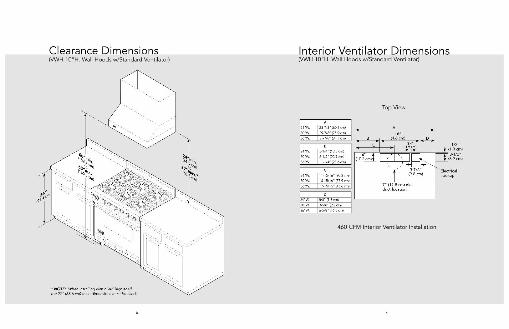
Clearance Dimensions
7
Interior Ventilator Dimensions
460 CFM Interior Ventilator Installation
Top View
(VWH 10”H. Wall Hoods w/Standard Ventilator)(VWH 10”H. Wall Hoods w/Standard Ventilator)

9
Dimensions & Specifications
8
(VWH 18”H. 24” Deep Wall Hoods 30”, 36”, 42”, 48”, 54”, & 60”)(VWH 18”H. 27” Deep Wall Hoods 36”, 48”, & 60”)
* A 1,200 CFM interior- or exterior-power ventilator should be used when installed over range/rangetop with gas char-grill.Max duct run is 50 ft.
** It is recommended that the 1,500 CFM ventilator be used with longer duct runs. Max duct run is 75 ft.NOTE: Maximum amp rating for hoods includes recommended ventilator kit rating; All products must be hard wired with 2-wire with ground. An interior- or exterior-power ventilator kit must be purchased for installation with all 18”H. hoods.
Clearance Dimensions(VWH 18”H. Wall Hoods)
NOTE: Optional duct cover sold separately.
VWH 18”H. Wall HoodsDescription 30” 36” 42” 48” 54” 60”
Duct cover width 29-7/8”(75.9 cm)
35-7/8”(91.1 cm)
41-7/8”(106.4 cm)
47-7/8”(121.6 cm)
53-7/8”(136.8 cm)
59-7/8”(152.1 cm)
Duct cover depth 12” (30.5 cm)Duct cover height 12” (30.5 cm)Number of lights 2 2 2 3 3 4
Number of filters 2 2 2 3 3 4
Heat lamps 1 1 1 2 2 2
Interior ventilator kits VINV300/600/1200
VINV300/600/1200
VINV600/1200
VINV1200* VINV1200* VINV1200*
Exterior ventilator kits DEV900/1200*
DEV900/1200*
DEV900/1200*
DEV1200*/1500**
DEV1200*/1500**
DEV1200*/1500**
In-line ventilator kits DIL900/1200 DIL900/1200 DIL900/1200 DIL1200 DIL1200 DIL1200
Interior duct size 7”/10”(17.8/25.4 cm)
7”/10”(17.8/25.4 cm)
7”/10”(17.8/25.4 cm)
10”(25.4 cm)
10”(25.4 cm)
10”(25.4 cm)
Exterior duct size 10” (25.4 cm)
Interior—Maximum amps 4.9/5.9 4.9/5.9 11.5 11.5 11.5 11.5
Exterior—Maximum amps 8.7/6.0 8.7/6.0 8.7/6.0 8.5/9.2 8.5/9.2 8.9/9.2
In-Line—Maximum amps 6.0/7.9 6.0/7.9 6.0/7.9 10.3 10.3 10.7
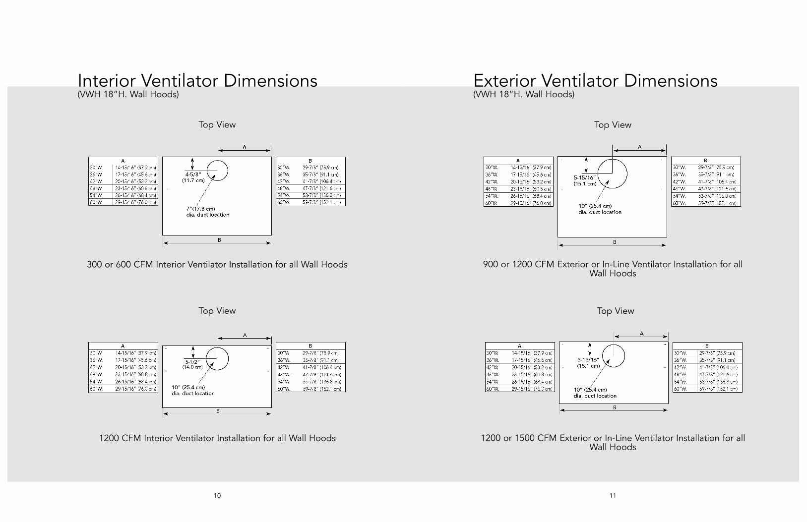
Exterior Ventilator Dimensions
11
Interior Ventilator Dimensions
10
900 or 1200 CFM Exterior or In-Line Ventilator Installation for allWall Hoods
1200 or 1500 CFM Exterior or In-Line Ventilator Installation for allWall Hoods
300 or 600 CFM Interior Ventilator Installation for all Wall Hoods
1200 CFM Interior Ventilator Installation for all Wall Hoods
Top View Top View
Top View Top View
(VWH 18”H. Wall Hoods) (VWH 18”H. Wall Hoods)
1312
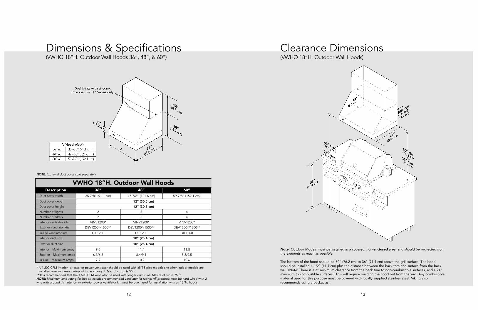
Dimensions & Specifications(VWHO 18”H. Outdoor Wall Hoods 36”, 48”, & 60”)
* A 1,200 CFM interior- or exterior-power ventilator should be used with all T-Series models and when i ndoor models areinstalled over range/rangetop with gas char-grill. Max duct run is 50 ft.
** It is recommended that the 1,500 CFM ventilator be used with longer duct runs. Max duct run is 75 ft.NOTE: Maximum amp rating for hoods includes recommended ventilator kit rating; All products must be hard wired with 2-wire with ground. An interior- or exterior-power ventilator kit must be purchased for installation with all 18”H. hoods.
NOTE: Optional duct cover sold separately.
Clearance Dimensions(VWHO 18”H. Outdoor Wall Hoods)
Note: Outdoor Models must be installed in a covered, non-enclosed area, and should be protected fromthe elements as much as possible.
The bottom of the hood should be 30” (76.2 cm) to 36” (91.4 cm) above the grill surface. The hoodshould be installed 4-1/2” (11.4 cm) plus the distance between the back trim and surface from the backwall. (Note: There is a 3” minimum clearance from the back trim to non-combustible surfaces, and a 24”minimum to combustible surfaces.) This will require building the hood out from the wall. Any combustiblematerial used for this purpose must be covered with locally-supplied stainless steel. Viking alsorecommends using a backsplash.
VWHO 18”H. Outdoor Wall HoodsDescription 36” 48” 60”
Duct cover width 35-7/8” (91.1 cm) 47-7/8” (121.6 cm) 59-7/8” (152.1 cm)
Duct cover depth 12” (30.5 cm)Duct cover height 12” (30.5 cm)Number of lights 2 3 4Number of filters 2 3 4Interior ventilator kits VINV1200* VINV1200* VINV1200*Exterior ventilator kits DEV1200*/1500** DEV1200*/1500** DEV1200*/1500**
In-line ventilator kits DIL1200 DIL1200 DIL1200Interior duct size 10” (25.4 cm)
Exterior duct size 10” (25.4 cm)
Interior—Maximum amps 9.0 11.4 11.8Exterior—Maximum amps 6.1/6.8 8.4/9.1 8.8/9.5In-Line—Maximum amps 7.9 10.2 10.6
15
Dimensions & Specifications
14
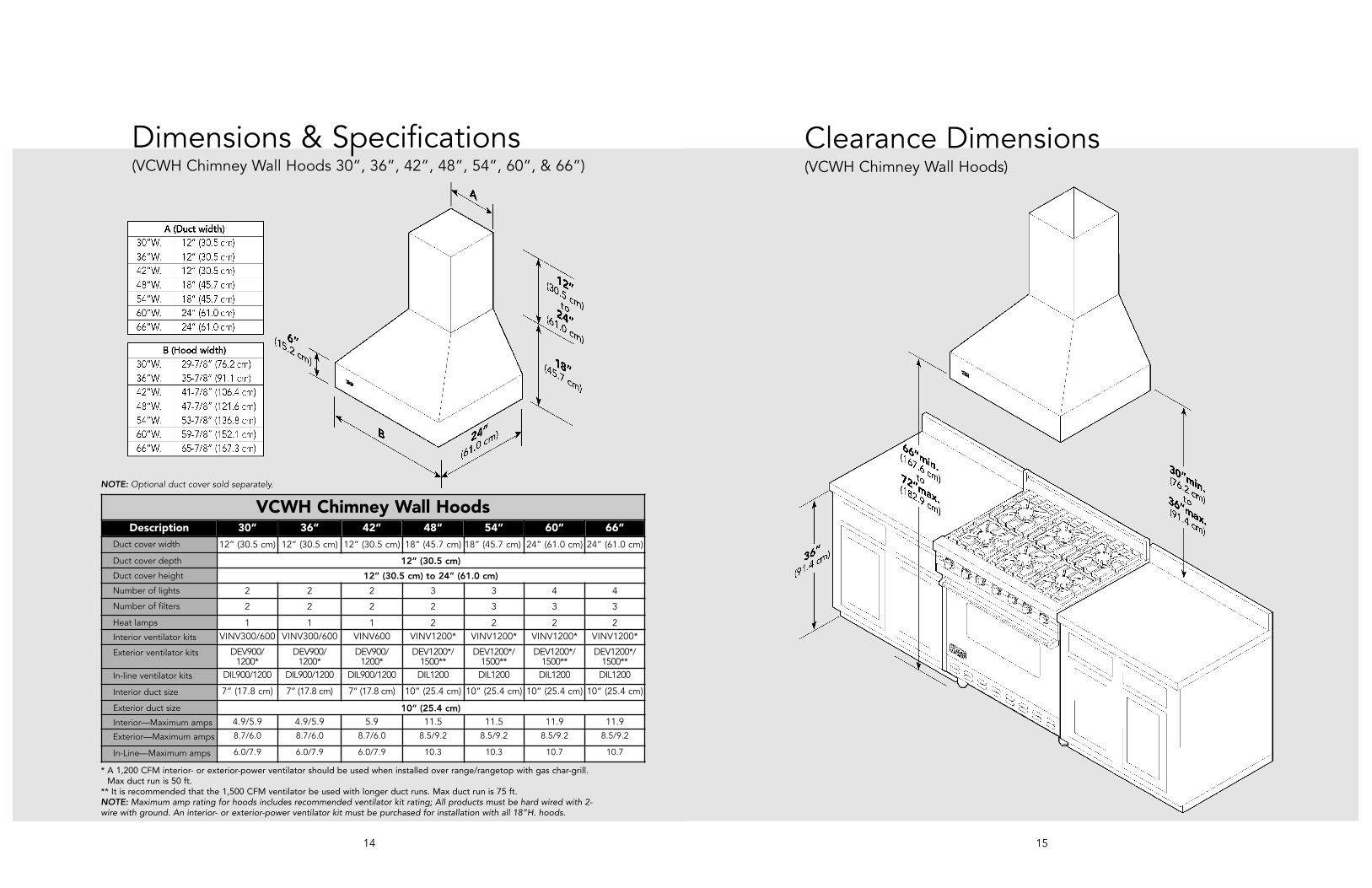
(VCWH Chimney Wall Hoods 30”, 36”, 42”, 48”, 54”, 60”, & 66”)
* A 1,200 CFM interior- or exterior-power ventilator should be used when installed over range/rangetop with gas char-grill.Max duct run is 50 ft.
** It is recommended that the 1,500 CFM ventilator be used with longer duct runs. Max duct run is 75 ft.NOTE: Maximum amp rating for hoods includes recommended ventilator kit rating; All products must be hard wired with 2-wire with ground. An interior- or exterior-power ventilator kit must be purchased for installation with all 18”H. hoods.
Clearance Dimensions(VCWH Chimney Wall Hoods)
NOTE: Optional duct cover sold separately.
VCWH Chimney Wall HoodsDescription 30” 36” 42” 48” 54” 60” 66”
Duct cover width 12” (30.5 cm) 12” (30.5 cm) 12” (30.5 cm) 18” (45.7 cm) 18” (45.7 cm) 24” (61.0 cm) 24” (61.0 cm)
Duct cover depth 12” (30.5 cm)Duct cover height 12” (30.5 cm) to 24” (61.0 cm)Number of lights 2 2 2 3 3 4 4
Number of filters 2 2 2 2 3 3 3
Heat lamps 1 1 1 2 2 2 2Interior ventilator kits VINV300/600 VINV300/600 VINV600 VINV1200* VINV1200* VINV1200* VINV1200*
Exterior ventilator kits DEV900/1200*
DEV900/1200*
DEV900/1200*
DEV1200*/1500**
DEV1200*/1500**
DEV1200*/1500**
DEV1200*/1500**
In-line ventilator kits DIL900/1200 DIL900/1200 DIL900/1200 DIL1200 DIL1200 DIL1200 DIL1200
Interior duct size 7” (17.8 cm) 7” (17.8 cm) 7” (17.8 cm) 10” (25.4 cm) 10” (25.4 cm) 10” (25.4 cm) 10” (25.4 cm)
Exterior duct size 10” (25.4 cm)Interior—Maximum amps 4.9/5.9 4.9/5.9 5.9 11.5 11.5 11.9 11.9
Exterior—Maximum amps 8.7/6.0 8.7/6.0 8.7/6.0 8.5/9.2 8.5/9.2 8.5/9.2 8.5/9.2
In-Line—Maximum amps 6.0/7.9 6.0/7.9 6.0/7.9 10.3 10.3 10.7 10.7

Interior Ventilator Dimensions
16
Exterior Ventilator Dimensions
17
900 or 1200 CFM Exterior or In-Line Ventilator Installation for 30”, 36”, & 42” models
900, 1200 or 1500 CFM Exterior or In-Line Ventilator Installationfor 48”, 54”, 60”, & 66” models
300 or 600 CFM Interior Ventilator Installation for 30”, 36”, & 42” models
1200 CFM Interior Ventilator Installation for 48”, 54”, 60”, & 66” models
Top View Top View
Top View Top View
(VCWH Chimney Wall Hoods) (VCWH Chimney Wall Hoods)

19
Dimensions & Specifications
18
(DCWH Classic Chimney Hoods 30”, 36”, 42”, & 48”)
* A 1,200 CFM interior- or exterior-power ventilator should be used when installed over range/rangetop with gas char-grill.Max duct run is 50 ft.
** It is recommended that the 1,500 CFM ventilator be used with longer duct runs. Max duct run is 75 ft.NOTE: Maximum amp rating for hoods includes recommended ventilator kit rating; All products must be hard wired with 2-wire with ground. An interior- or exterior-power ventilator kit must be purchased for installation with all 18”H. hoods.
Clearance Dimensions(DCWH Classic Chimney Hoods)
DCWH Classic Chimney Wall HoodsDescription 30” 36” 42” 48”
Duct cover width 10” (25.4 cm) 12” (30.5 cm) 12” (30.5 cm) 18” (45.7 cm)
Duct cover depth 12” (30.5 cm)Duct cover height 18” (45.7 cm) to
30” (76.2 cm)16” (40.6 cm) to
28” (71.1 cm)16” (40.6 cm) to
28” (71.1 cm)16” (40.6 cm) to
28” (71.1 cm)Number of lights 2 2 2 3Number of filters 2 2 3 3
Interior ventilator kits VINV300/600 VINV300/600 VINV600 VINV1200*
Exterior ventilator kits DEV900/1200* DEV900/1200* DEV900/1200* DEV1200*/1500**
In-line ventilator kits DIL900/1200 DIL900/1200 DIL900/1200 DIL1200
Interior duct size 7” (17.8 cm) 7” (17.8 cm) 7” (17.8 cm) 10” (25.4 cm)
Exterior duct size 10” (25.4 cm)
Interior—Maximum amps 2.8/3.8 2.8/3.8 3.8 7.3
Exterior—Maximum amps 6.6/3.9 6.6/3.9 6.6/3.9 4.3/5.1
In-Line—Maximum amps 3.9/5.7 3.9/5.7 3.9/5.7 6.1
NOTE: For best performance, it is recommended that the bottom of the hood be 30” (76.2 cm) to 36” (91.4 cm) above the countertop. These dimensionsprovide for safe and efficient operation of the hood.
2120
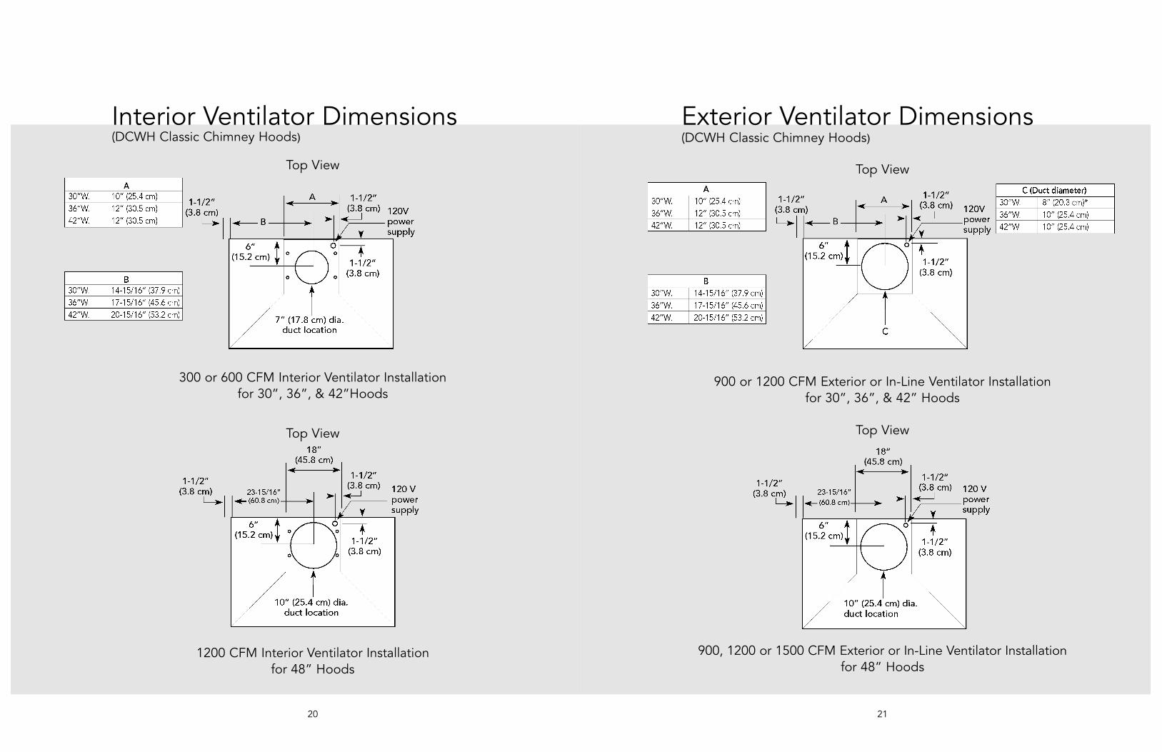
Exterior Ventilator Dimensions Interior Ventilator Dimensions
300 or 600 CFM Interior Ventilator Installation for 30”, 36”, & 42”Hoods
900 or 1200 CFM Exterior or In-Line Ventilator Installation for 30”, 36”, & 42” Hoods
Top View Top View
Top View Top View
900, 1200 or 1500 CFM Exterior or In-Line Ventilator Installationfor 48” Hoods
1200 CFM Interior Ventilator Installationfor 48” Hoods
(DCWH Classic Chimney Hoods) (DCWH Classic Chimney Hoods)
2322
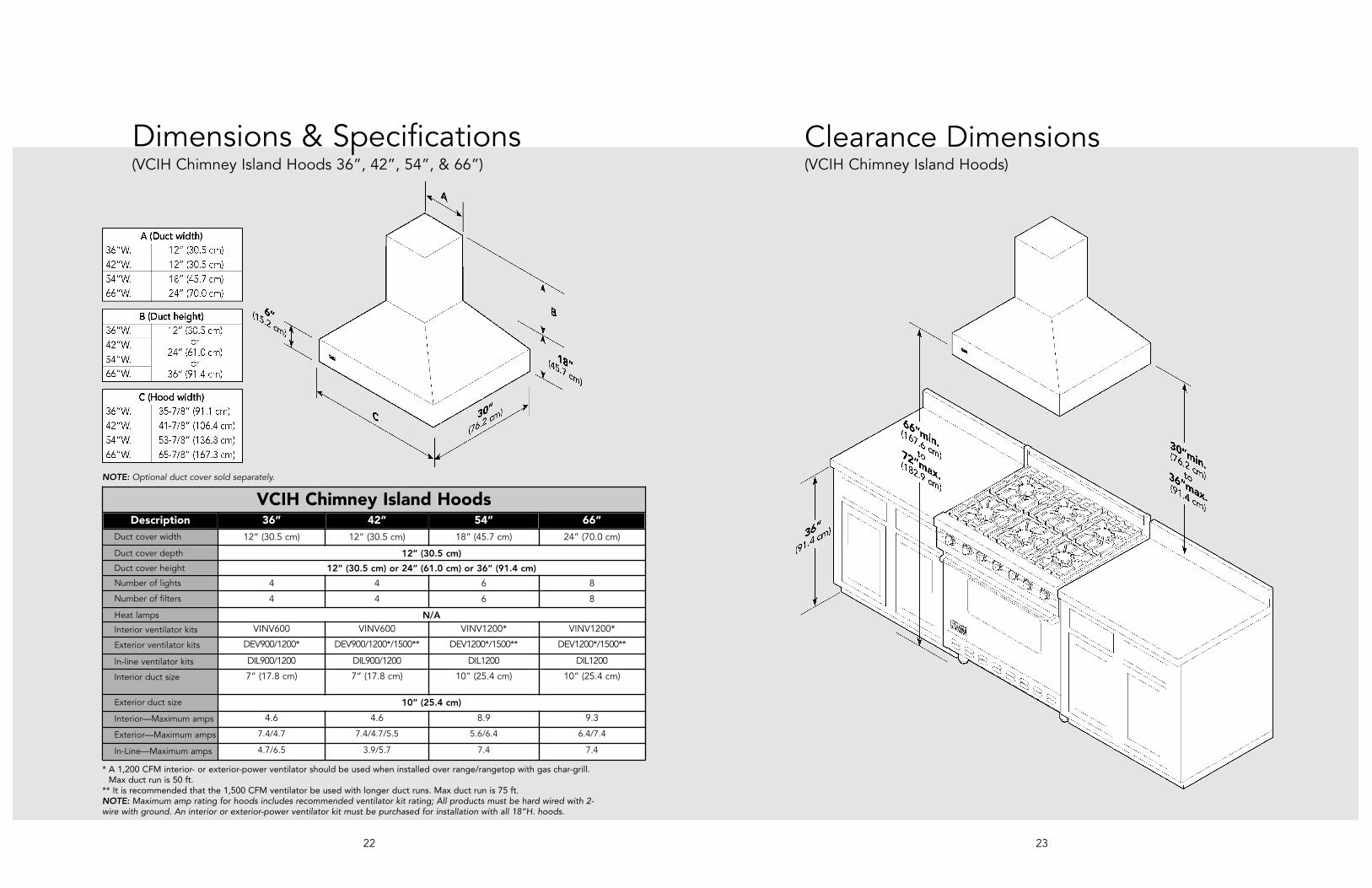
* A 1,200 CFM interior- or exterior-power ventilator should be used when installed over range/rangetop with gas char-grill.Max duct run is 50 ft.
** It is recommended that the 1,500 CFM ventilator be used with longer duct runs. Max duct run is 75 ft.NOTE: Maximum amp rating for hoods includes recommended ventilator kit rating; All products must be hard wired with 2-wire with ground. An interior or exterior-power ventilator kit must be purchased for installation with all 18”H. hoods.
Dimensions & Specifications Clearance Dimensions(VCIH Chimney Island Hoods)
NOTE: Optional duct cover sold separately.
(VCIH Chimney Island Hoods 36”, 42”, 54”, & 66”)
VCIH Chimney Island HoodsDescription 36” 42” 54” 66”
Duct cover width 12” (30.5 cm) 12” (30.5 cm) 18” (45.7 cm) 24” (70.0 cm)
Duct cover depth 12” (30.5 cm)Duct cover height 12” (30.5 cm) or 24” (61.0 cm) or 36” (91.4 cm)Number of lights 4 4 6 8
Number of filters 4 4 6 8
Heat lamps N/AInterior ventilator kits VINV600 VINV600 VINV1200* VINV1200*
Exterior ventilator kits DEV900/1200* DEV900/1200*/1500** DEV1200*/1500** DEV1200*/1500**
In-line ventilator kits DIL900/1200 DIL900/1200 DIL1200 DIL1200
Interior duct size 7” (17.8 cm) 7” (17.8 cm) 10” (25.4 cm) 10” (25.4 cm)
Exterior duct size 10” (25.4 cm)
Interior—Maximum amps 4.6 4.6 8.9 9.3
Exterior—Maximum amps 7.4/4.7 7.4/4.7/5.5 5.6/6.4 6.4/7.4
In-Line—Maximum amps 4.7/6.5 3.9/5.7 7.4 7.4

Exterior Ventilator Dimensions
25
Interior Ventilator Dimensions
24
900 or 1200 CFM Exterior or In-Line Ventilator Installation for all Chimney Island Hoods
900, 1200 or 1500 CFM Exterior or In-Line Ventilator Installation for all Chimney Island Hoods
600 CFM Interior Ventilator Installation for all Chimney Island Hoods
1200 CFM Interior Ventilator Installation for all Chimney Island Hoods
Top View Top View
Top View Top View
(VCIH Chimney Island Hoods) (VCIH Chimney Island Hoods)

2726
Dimensions & Specifications(VBCV Wall Custom Ventilator System 30”, 36”, 42”, 48”, 54”, 60” & 66”)
* A 1,200 CFM interior- or exterior-power ventilator should be used when installed over range/rangetop with gas char-grill.Max duct run is 50 ft.
** It is recommended that the 1,500 CFM ventilator be used with longer duct runs. Max duct run is 75 ft.NOTE: Maximum amp rating for hoods includes recommended ventilator kit rating; All products must be hard wired with 2-wire with ground. An interior- or exterior-power ventilator kit must be purchased for installation with all 18”H. hoods.
Bottom Cutout Dimensions
*For best results,center the unit overthe burners of thecooking product(front to back; rightto left).
Wall HoodsDescription A (Hood Width) B (Hood Depth)
30” W. 27-7/16” (69.7 cm) 21-7/16” (54.5 cm)36” W. 33-7/16” (84.9 cm) 21-7/16” (54.5 cm)42” W. 39-7/16” (100.2 cm) 21-7/16” (54.5 cm)48” W. 45-7/16” (115.4 cm) 21-7/16” (54.5 cm)54” W. 51-7/16” (130.7 cm) 21-7/16” (54.5 cm)60” W. 57-7/16” (145.9 cm) 21-7/16” (54.5 cm)66” W. 63-7/16” (161.1 cm) 21-7/16” (54.5 cm)
Make sure the back wallof the custom hoodcanopy is flush with thecutout so the ventilatorsystem may be mountedas shown on page 25.
Installing Hood Canopy
Custom HoodCanopy
1) Position ventilatorsystem inside of thecustom hood canopyand center it front toback and left to right.
2) Bottom mounting holesfasten ventilator systemto bottom of customhood canopy with thescrews provided.
Built-In VentilatorSystem
3) OPTIONALRear mounting holes fastenventilator system to rear ofcustom hood canopy.
(Custom Hood Canopy Cutouts)
VBCV Wall Custom Ventilator SystemDescription 30” 36” 42” 48” 54” 60” 66”
Number of lights 2 2 2 3 3 4 4
Number of filters 2 2 2 3 3 4 4
Heat lamps 1 1 1 2 2 2 2
Interior ventilator kits VINV300/600/1200*
VINV300/600/1200*
VINV600/1200*
VINV1200* VINV1200* VINV1200* VINV1200*
Exterior ventilator kits DEV900/1200*
DEV900/1200*
DEV900/1200*
DEV1200*/1500**
DEV1200*/1500**
DEV1200*/1500**
DEV1200*/1500**
In-line ventilator kits DIL900/1200 DIL900/1200 DIL900/1200 DIL1200 DIL1200 DIL1200 DIL1200
Interior duct size 7”/10”(17.8/25.4 cm)
7”/10”(17.8/25.4 cm)
7”/10”(17.8/25.4 cm)
10”(25.4 cm)
10”(25.4 cm)
10”(25.4 cm)
10”(25.4 cm)
Exterior duct size 10” (25.4 cm)
Interior—Maximum amps 5.9/9.0 5.9/9.0 5.9/9.0 11.5 11.5 11.9 11.9
Exterior—Maximum amps 8.7/6.0 8.7/6.0 8.7/6.0 8.5/9.2 8.5/9.2 8.9/9.2 8.9/9.2
In-Line—Maximum amps 6.0/7.9 6.0/7.9 6.0/7.9 10.3 10.3 10.7 10.7
29
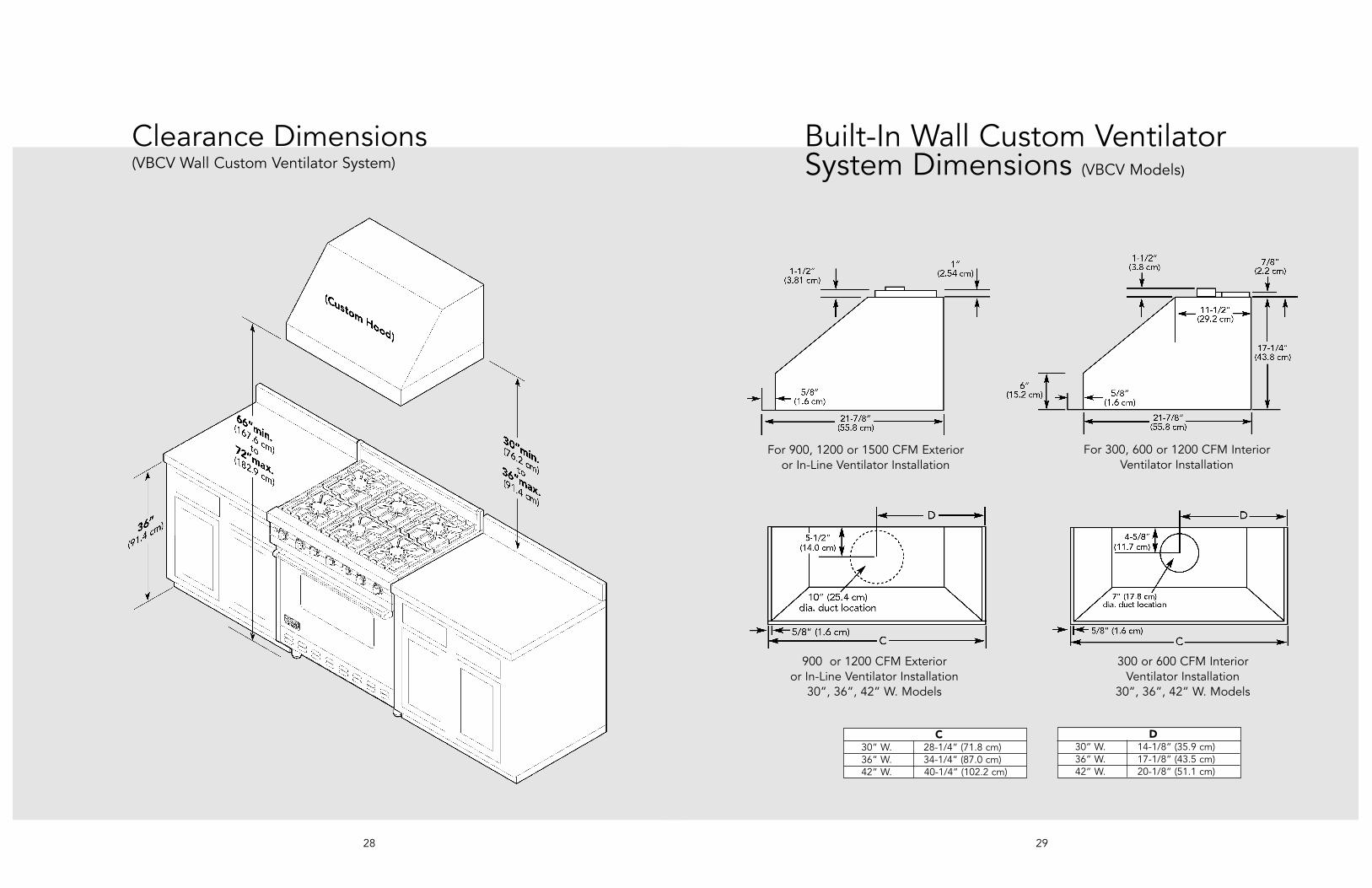
Built-In Wall Custom VentilatorSystem Dimensions (VBCV Models)
For 900, 1200 or 1500 CFM Exterioror In-Line Ventilator Installation
For 300, 600 or 1200 CFM InteriorVentilator Installation
900 or 1200 CFM Exterioror In-Line Ventilator Installation
30”, 36”, 42” W. Models
300 or 600 CFM InteriorVentilator Installation
30”, 36”, 42” W. Models
C30” W. 28-1/4” (71.8 cm)36” W. 34-1/4” (87.0 cm)42” W. 40-1/4” (102.2 cm)
D30” W. 14-1/8” (35.9 cm)36” W. 17-1/8” (43.5 cm)42” W. 20-1/8” (51.1 cm)
28
Clearance Dimensions(VBCV Wall Custom Ventilator System)

3130
1200 or 1500 CFM Exterior or In-Line Ventilator Installation48”, 54”, 60”, 66” W. Models
1200 CFM Interior Ventilator Installation30”, 36”, 42”, 48”, 54”, 60”, 66” W. Models
Built-In Wall Custom VentilatorSystem Dimensions (VBCV Models)
C30” W. 28-1/4” (71.8 cm)36” W. 34-1/4” (87.0 cm)42” W. 40-1/4” (102.2 cm)48” W. 46-1/4” (117.5 cm)54” W. 52-1/4” (132.7 cm)60” W. 58-1/4” (148.0 cm)66” W. 64-1/4” (163.2 cm)
D30” W. 14-1/8” (35.9 cm)36” W. 17-1/8” (43.5 cm)42” W. 20-1/8” (51.1 cm)48” W. 23-1/8” (58.7 cm)54” W. 26-1/8” (66.4 cm)60” W. 29-1/8” (74.0 cm)66” W. 32-1/8” (81.6 cm)
Planning Information
Proper installation of ducting is extremelyimportant to ensure maximum performancefrom any ventilation product.• All CFMs are based on tests at 0.1 static
pressure: without applying static pressure, CFMwould be greatly overstated.
• Straight runs and gradual turns are best; forexample, each 90º elbow is equivalent to 5-10feet (1.52-3.05 cm) of straight run.
• Never use flexible duct; it creates back pressure/airturbulence and greatly reduces performance.
• Proper performance is dependent on properducting; make sure that a qualified and trainedinstaller is used.
• Check with a qualified and trained installer orlocal codes for makeup air requirement, if any.
• Max. amp rating for hoods includesrecommended ventilator kit rating; all productsmust be hard wired direct with 2-wire with ground.
Plan where the duct work will be located. Installproper-sized duct work, and roof or wall cap for thetype of blower you are using. Recommended hoodlocations for the most common installations areshown. Adjust your measurements for various heightsof ceilings, soffits, cabinets, or ranges/rangetops.
Check Framing
NOTE: Because of the weight of the hood make surethat the mounting screws are driven into the framingand not just the drywall. It may be necessary to drilladditional holes in the canopy for proper alignment.
33
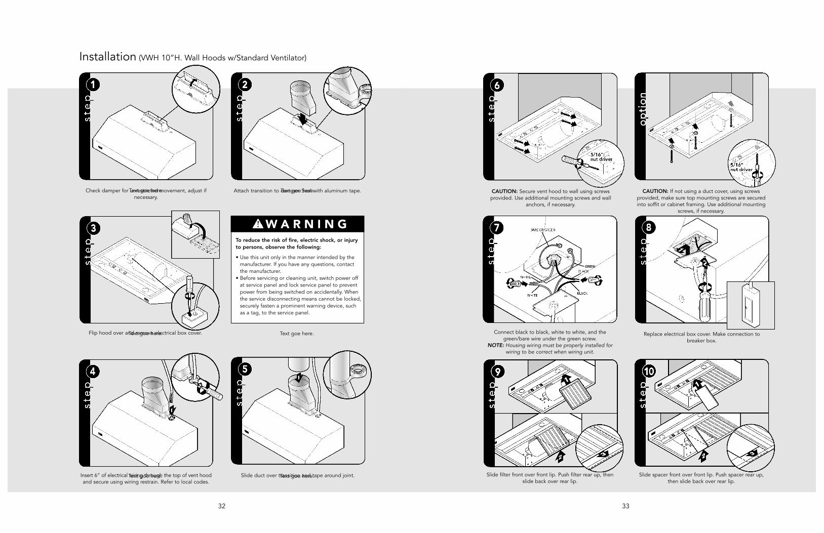
CAUTION: If not using a duct cover, using screwsprovided, make sure top mounting screws are securedinto soffit or cabinet framing. Use additional mounting
screws, if necessary.
Connect black to black, white to white, and thegreen/bare wire under the green screw.
NOTE: Housing wiring must be properly installed forwiring to be correct when wiring unit.
Replace electrical box cover. Make connection tobreaker box.
Slide spacer front over front lip. Push spacer rear up,then slide back over rear lip.
Slide filter front over front lip. Push filter rear up, thenslide back over rear lip.
CAUTION: Secure vent hood to wall using screwsprovided. Use additional mounting screws and wall
anchors, if necessary.
32
Text goe here. Text goe here.
Text goe here. Text goe here.
Text goe here. Text goe here.
Check damper for unrestricted movement, adjust ifnecessary.
Attach transition to damper. Seal with aluminum tape.
Flip hood over and remove electrical box cover.
Insert 6” of electrical wiring through the top of vent hoodand secure using wiring restrain. Refer to local codes.
Slide duct over transition and tape around joint.
Installation (VWH 10”H. Wall Hoods w/Standard Ventilator)
W A R N I N GTo reduce the risk of fire, electric shock, or injuryto persons, observe the following:
• Use this unit only in the manner intended by themanufacturer. If you have any questions, contactthe manufacturer.
• Before servicing or cleaning unit, switch power offat service panel and lock service panel to preventpower from being switched on accidentally. Whenthe service disconnecting means cannot be locked,securely fasten a prominent warning device, suchas a tag, to the service panel.
35
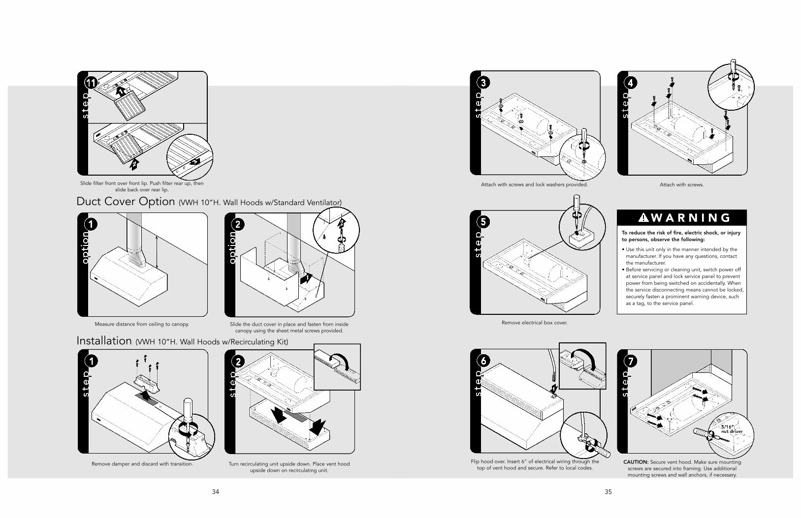
CAUTION: Secure vent hood. Make sure mountingscrews are secured into framing. Use additionalmounting screws and wall anchors, if necessary.
Remove electrical box cover.
Flip hood over. Insert 6” of electrical wiring through thetop of vent hood and secure. Refer to local codes.
Attach with screws and lock washers provided. Attach with screws.
W A R N I N GTo reduce the risk of fire, electric shock, or injuryto persons, observe the following:
• Use this unit only in the manner intended by themanufacturer. If you have any questions, contactthe manufacturer.
• Before servicing or cleaning unit, switch power offat service panel and lock service panel to preventpower from being switched on accidentally. Whenthe service disconnecting means cannot be locked,securely fasten a prominent warning device, suchas a tag, to the service panel.
34
Remove damper and discard with transition. Turn recirculating unit upside down. Place vent hoodupside down on recirculating unit.
Installation (VWH 10”H. Wall Hoods w/Recirculating Kit)
Measure distance from ceiling to canopy. Slide the duct cover in place and fasten from insidecanopy using the sheet metal screws provided.
Duct Cover Option (VWH 10”H. Wall Hoods w/Standard Ventilator)
Slide filter front over front lip. Push filter rear up, thenslide back over rear lip.
37
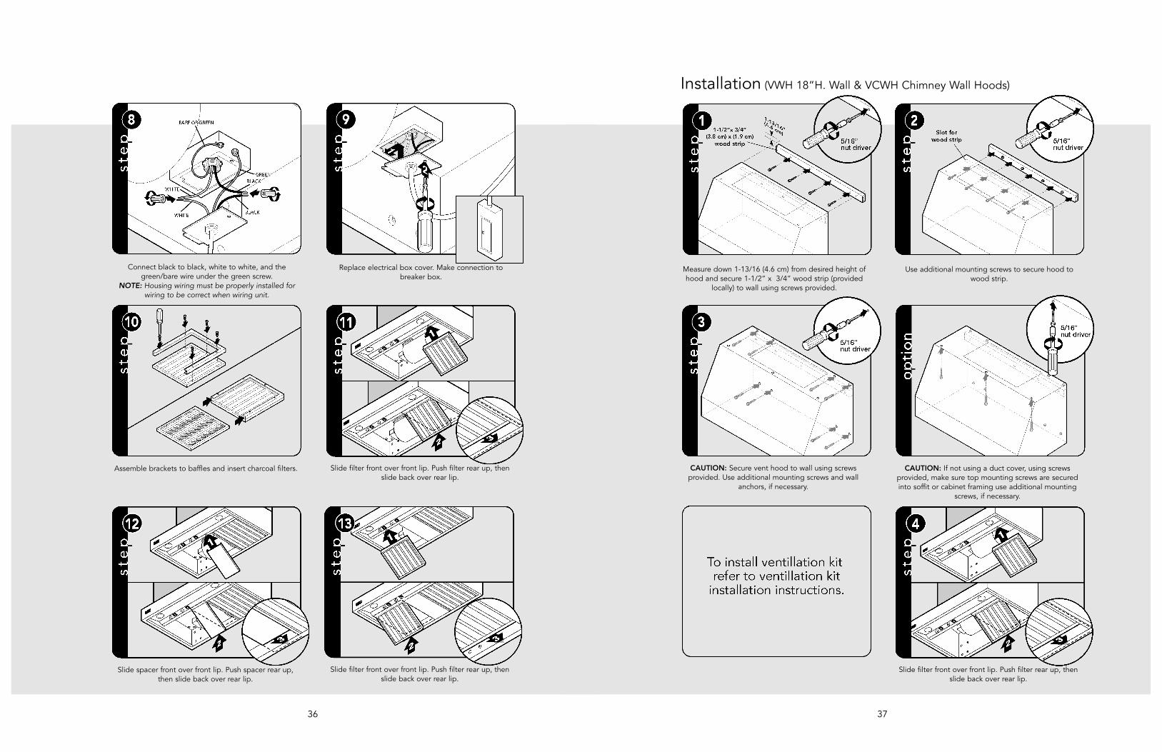
Measure down 1-13/16 (4.6 cm) from desired height ofhood and secure 1-1/2” x 3/4” wood strip (provided
locally) to wall using screws provided.
Use additional mounting screws to secure hood towood strip.
Installation (VWH 18”H. Wall & VCWH Chimney Wall Hoods)
CAUTION: Secure vent hood to wall using screwsprovided. Use additional mounting screws and wall
anchors, if necessary.
CAUTION: If not using a duct cover, using screwsprovided, make sure top mounting screws are securedinto soffit or cabinet framing use additional mounting
screws, if necessary.
Slide filter front over front lip. Push filter rear up, thenslide back over rear lip.
36
Connect black to black, white to white, and thegreen/bare wire under the green screw.
NOTE: Housing wiring must be properly installed forwiring to be correct when wiring unit.
Replace electrical box cover. Make connection tobreaker box.
Assemble brackets to baffles and insert charcoal filters. Slide filter front over front lip. Push filter rear up, thenslide back over rear lip.
Slide filter front over front lip. Push filter rear up, thenslide back over rear lip.
Slide spacer front over front lip. Push spacer rear up,then slide back over rear lip.
39
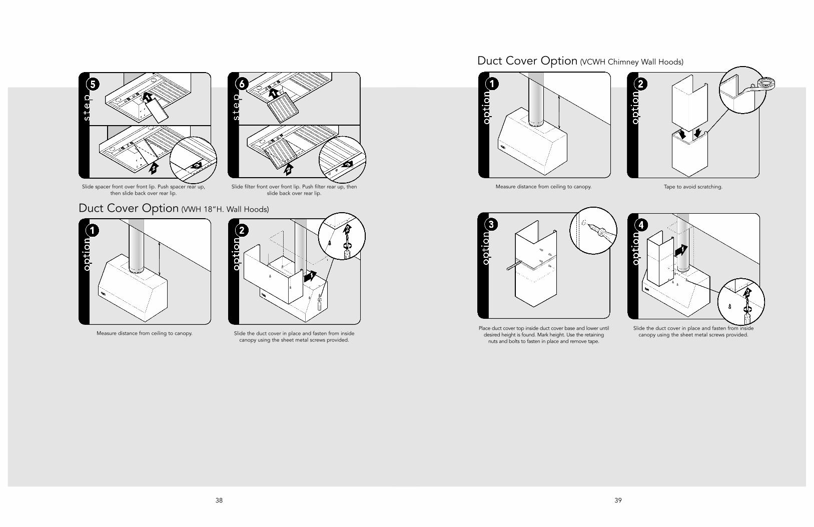
Place duct cover top inside duct cover base and lower untildesired height is found. Mark height. Use the retaining
nuts and bolts to fasten in place and remove tape.
Slide the duct cover in place and fasten from insidecanopy using the sheet metal screws provided.
Measure distance from ceiling to canopy. Tape to avoid scratching.
Duct Cover Option (VCWH Chimney Wall Hoods)
38
Slide spacer front over front lip. Push spacer rear up,then slide back over rear lip.
Slide filter front over front lip. Push filter rear up, thenslide back over rear lip.
Measure distance from ceiling to canopy. Slide the duct cover in place and fasten from insidecanopy using the sheet metal screws provided.
Duct Cover Option (VWH 18”H. Wall Hoods)
41
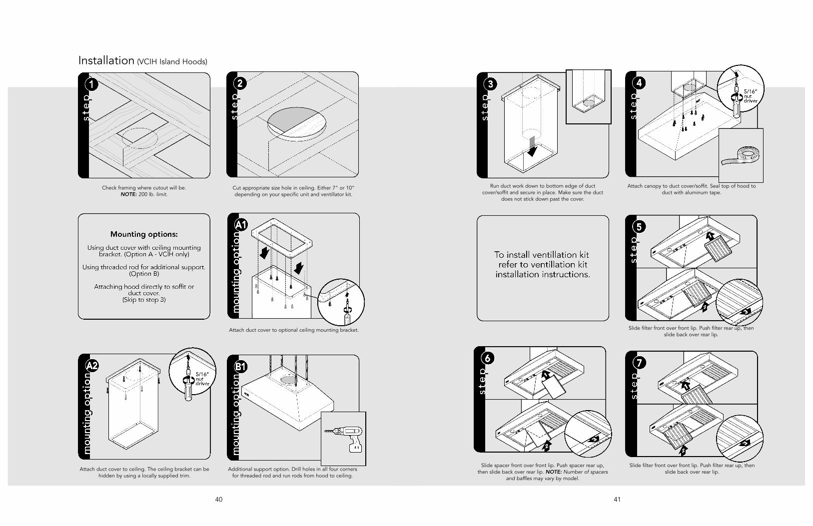
Attach canopy to duct cover/soffit. Seal top of hood toduct with aluminum tape.
Run duct work down to bottom edge of ductcover/soffit and secure in place. Make sure the duct
does not stick down past the cover.
Slide filter front over front lip. Push filter rear up, thenslide back over rear lip.
Slide spacer front over front lip. Push spacer rear up,then slide back over rear lip. NOTE: Number of spacers
and baffles may vary by model.
Slide filter front over front lip. Push filter rear up, thenslide back over rear lip.
40
Check framing where cutout will be. NOTE: 200 lb. limit.
Cut appropriate size hole in ceiling. Either 7” or 10”depending on your specific unit and ventillator kit.
Installation (VCIH Island Hoods)
Attach duct cover to optional ceiling mounting bracket.
Attach duct cover to ceiling. The ceiling bracket can behidden by using a locally supplied trim.
Additional support option. Drill holes in all four cornersfor threaded rod and run rods from hood to ceiling.

4342
Measure down 1-13/16 (4.6 cm) from desired height ofhood and secure 1-1/2” x 3/4” wood strip (not
included) to wall using screws provided.
Use additional mounting screws to secure hood towood strip.
Installation (DCWH Classic Chimney Wall Hoods)
CAUTION: Secure vent hood to wall using screws provided.Make sure mounting screws are secured into frame. Useadditional mounting screws and wall anchors, if necessary.
CAUTION: If not using a duct cover, using screws providedmake sure top mounting screws are secured into soffit orcabinet frame. Use additional mounting screws, if necessary.
Slide filter front over front lip. Push filter rear up, thenslide back over rear lip.
Slide spacer front over front lip. Push spacer rear up,then slide back over rear lip.
Slide filter front over front lip. Push filter rear up, thenslide back over rear lip.
Measure distance from ceiling to canopy. Tape to avoid scratching.
Duct Cover Option (DCWH Classic Chimney Wall Hoods)
44
Service & Registration
Service & PartsOnly authorized replacement parts may beused in performing service on the appliance.Do not repair or replace any part of theappliance unless specifically recommended inthe manual. All other servicing should bereferred to a qualified technician.
Record the following information indicatedbelow. You will need it if service is ever required.The serial number and model number for yourappliance are located on the identification platemounted on the inside of the hood canopy.
Model number
_________________________________________
Serial number
_________________________________________
Date of purchase
_________________________________________
Date installed
_________________________________________
Dealer's name
_________________________________________
Address
_________________________________________
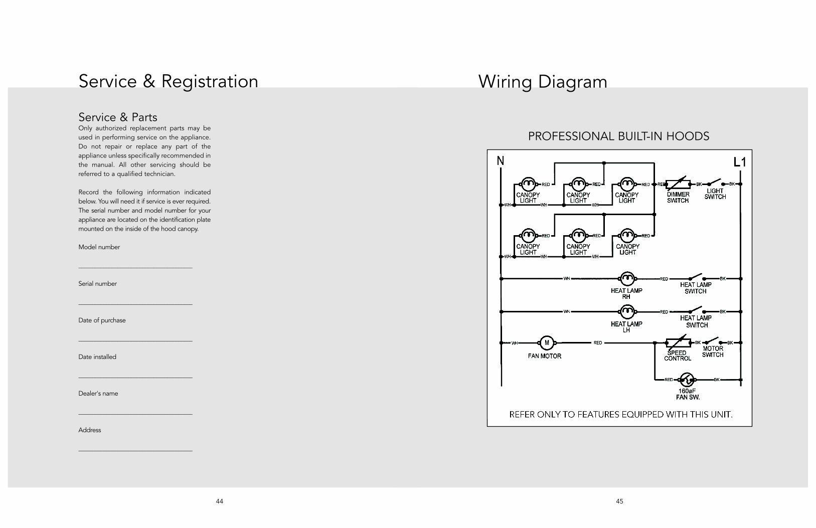
Wiring Diagram
45
PROFESSIONAL BUILT-IN HOODS

4746