Embed Size (px)
Citation preview
1
Video Algorithms andArchitectures
K.A. VissersPhilips Research
andA.K. Riemens, R.J. Schutten,
G. de HaanPhilips Research
Eindhoven, The Netherlands
Contents
• Context of TV systems• Video Format Conversion• De-interlacing and Up-Conversion• Motion Estimation and Motion Compensation• Several Architectures• Conclusion

2
Context of TV systems
• Consumer electronics: price for electronics$50 - 100
• Real-time performance: no loss of data,garanteed response
• Embedded systems, certainly for the displayprocessing
• Image quality is important
Context of TV systems
Frequencies for standard resolution TV:• PAL: 864 pixels, 625/2=312 lines, 50 fields /sec, interlace• NTSC: 864 pixels, 525/2=262 lines, 60 fields/sec, interlace
In total:13.5 million samples per second,luminance (y) and chrominance (u and v, subsampled),
typically 8-10 bits data for luminance and 8 bits for color
System signal processing: 100 - 1000 operations per pixel:1.35 - 13.5 Billion operations per second,1.35 - 13.5 Gbyte per second internal bandwidth

3
Context of TV systems
Algorithms for picture quality improvements:• Sharpness “improvement”• Noise Reduction• De-interlace• Up-conversion
Increasing demand for conversion
WEB
DVD
VideoFormat
Conversion
50 Hz 2:150 Hz 2:160 Hz 2:160 Hz 2:1
100 Hz100 Hz2:12:1
72 Hz 1:172 Hz 1:185 Hz 1:185 Hz 1:195 Hz 1:195 Hz 1:1
::
50 Hz 2:150 Hz 2:160 Hz 2:160 Hz 2:124 Hz 1:124 Hz 1:125 Hz 1:125 Hz 1:130 Hz 1:130 Hz 1:1
::
CIFCIF
QCIFQCIF
1-25Hz/1:11-25Hz/1:1

4
Good reasons for different formats
Standardization is no option• Channel capacity differs• Viewing distance differs• History may be different• Screen brightness differs• Resolution requirements differ• Motion portrayal of different importance
Large Area Flicker on TV
Perception threshold for large area flicker as afunction of brightness
0.01
0.1
1
10
100
1000
30 38 47 60 72
Picture update frequency (Hz)
Bri
gh
tnes
s (c
d/m
2 o
r n
it))

5
Field Rate Conversion from 50 Hz to100Hz
t-T
t
t+2T
t+T
time
50 Hz inputfields
100 Hz outputfields
Original field
Interpolated field
Video format conversion problem
• Video contains time-discrete information:– In the temporal domain (discrete number of pict/s)– In the vertical domain (discrete number of lines)– Often in the horizontal domain (number of pels/line)
• Why not use interpolating and decimatinglow-pass filters to achieve our goal?– TV does not fulfill demands of sampling theorem in V and T
domains– Tracking viewers transform temporal frequencies

6
Field rate conversion
First De-interlace:• vertical temporal filter• motion estimation, followed by motion compensated
techniques
Next perform Up-conversion:• motion estimation, followed by motion compensated
techniques
In the end:• Motion compensated processing in any algorithm that
uses previous fields or frames: intra-field noisereduction etc.
What is interlace
11
3322
4455
66
1010
8877
99
xxFieldField
numbernumber
yy
n-1n-1 n-1n-1 nn
Spatial domainSpatial domain Temporal domainTemporal domain

7
Why de-interlace
• Some displays require progressive video(matrix type of displays)
• Eliminate line flicker, resolution loss withmotion, and alias
• Basic requirement for all scan conversion(even when converting from interlaced tointerlaced format)– e.g. field rate doubling preventing odd-odd-
even-even field sequence
De-interlacing, what is it?
n
n-1
Field number
odd
even
n
n-1
Field number
Calculate picture data at TV-lines not transmitted in the current field

8
Vertical Temporal Filter (VT)
Weightedsum
WeightedWeightedsumsum
Current fieldCurrent fieldCurrent fieldNeighbouringfield(s)
NeighbouringNeighbouringfield(s)field(s)
Ver
tical
pos
ition
Ver
tical
pos
ition
Ver
tical
pos
ition
Original pixel
Interpolated pixel
VT Median and moving edge
Edge field nEdge field n
Edge field n-1Edge field n-1
IdealIdealinterpolationinterpolation
VT-medianVT-medianinterpolationinterpolation

9
De-interlacing moving images
• The problem with motion is fundamental forall methods without motion compensation
Since• information of successive fields cannot be
combined because of motion, while singlefields cannot provide full vertical detail
• Motion compensation aims at achieving thesame quality for moving image parts as forstationary parts
De-interlacing summary
• For stationary images many methods performwell.
• For moving images, only motioncompensated methods perform reasonablygood.
• Motion compensated methods have beenintroduced in consumer products already.
Reference articles:
• G. de Haan and E.B. Bellers, “De-interlacing of Video data”, IEEE Tr. OnConsumer Electronics, Vol. 43, No. 3, August 1997, pp. 819-825.
• G. de Haan and E.B. Bellers, “De-interlacing-An overview, Overview articleaccepted for publication in the Proceedings of the IEEE .

10
Up-conversion
t-T
t
t+2T
t+T
time
50 Hz inputfields
100 Hz outputfields
Original field
Interpolated field
Picture rate conversionmoving object at picture rate
position
n-1 n n+1 n+2
original

11
Picture rate conversion,what if we just repeat the most recent image at the
output?
position
n-1 n n+1 n+2
original
repeated
Picture rate conversionthis is what we hoped for
position
n-1 n n+1 n+2
original
motion compensated

12
Tracking by viewerso moving images need to be sharp
Fixed eyeFixed eye MovingMovingdetaileddetailedobjectobject
High temporal frequencyHigh temporal frequencyBrightnessBrightness
TimeTime
Tracking eyeTracking eyeMovingMovingdetaileddetailedobjectobject
Zero temporal frequencyZero temporal frequency
MovingMovingfield offield of
viewview
BrightnessBrightness
TimeTime
Motion Compensated picture rate up-conversion
n
n-1
n-1/2
picture number
-D/2
D/2

13
Picture rate conversion,can we notice the improvement?
Non - Motion CompensatedMotion Compensated
Motion Estimation
So this is what we need:
• Is there anymotion?
• How fast?• into which
direction?
14
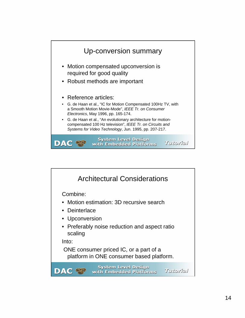
Up-conversion summary
• Motion compensated upconversion isrequired for good quality
• Robust methods are important
• Reference articles:• G. de Haan et al., “IC for Motion Compensated 100Hz TV, with
a Smooth Motion Movie-Mode”, IEEE Tr. on ConsumerElectronics, May 1996, pp. 165-174.
• G. de Haan et al., “An evolutionary architecture for motion-compensated 100 Hz television”, IEEE Tr. on Circuits andSystems for Video Technology, Jun. 1995, pp. 207-217.
Architectural Considerations
Combine:• Motion estimation: 3D recursive search• Deinterlace• Upconversion• Preferably noise reduction and aspect ratio
scalingInto: ONE consumer priced IC, or a part of a
platform in ONE consumer based platform.

15
Motion Estimation
The problem: find the best block position at a number of candidatepositions, comparing data of the current field/frame with date ofthe previous field/frame
Search area in the previous field/frame
Candidateposition(motion vector)block in the
current field
Motion Estimation Questions:
Find a perceptively good ME that requireslimited:
• external memory• internal memory• computational load.• What is a good ME? Iterative development loop:• Propose an algorithm for ME• Implement de-interlace and or up-conversion with it• Evaluate the video quality and the cost of implementation!Trade-offs with very non-linear and implicit cost functions

16
Choices for Motion Estimation
Algorithmic choices have a video quality andcost impact:
• Number of previous fields/frames used,e.g one frame (~ 1 Mbyte, external off chip memory)
• search range, typically +/- 12 - 16 in vertical direction,+/- 30-40 in horizontal direction (~ 10-100kByte internalmemory)
• Block size for comparison, typically 8x8 to 16x16• Accuracy of vectors, typically 0.25 pixel!, so 2D interpolation is
required inside the motion estimation• Number of pixels used in the calculation of the Sum of
differences: typically a sub-sample of a factor 2-4.
Combination of Motion Estimation,De-interlace and Up-conversion
• Combine the field/frame memories,• Combine the De-interlacing with Motion
Estimation: recursive de-interlacing• Use motion vectors for De-interlace• Calculate new motion vectors for Up-
conversion at proper temporal location(vector split)

17
System Trade-offs, solution 1
Existing IC (SAA 4991), used in high endPhilips TVs
• All pixel processing in dedicated synthesized hardware.• frame/field memories of chip• line memories for the search range on-chip.• Control settings and field level adjustment in a micro-controller
(8051)• Good video quality, implementation tuned for the TV market• Includes noise reduction and vertical scaling of the image• Runs synchronous with the video scanning frequency
System Trade-offs, solution 1)
• IC characteristics:CMOS 0.8 µm
97 mm2
980.000
27 or 32 MHz
PLCC841.8 WUART-bus±16 (H), ±9 (V) pixels
Process
Die Size
Transistor Count
Data Clock
Package
Dissipation
Interface
ME/MC Range

18
System Trade-offs solution 1)
MEME++
MCMC
MemoryMemory
MemoryMemory
TPMTPM
NRNR
Dedicated, synthesized,tuned solution
System trade-offs, solution 2)
Attempt to implement the de-interlacing and up-conversion completely in software exploiting theopportunities of Philips Trimedia VLIW core:
• Data parallelism 4 bytes in a word in the 32 bitarchitecture,
• Special Media instructions making SAD calculationsand Median calculations very efficient
• Instruction Level Parallelism exploiting: 4.5 out of 5issueslot effectively used over the complete program
• Some video quality limitations to achieve the softwaresolution

19
System Trade-offs, solution 2)
�70������70�����
6'5$0���0%�6'5$0���0%�
PCI-bus
PCI-cardPCI-card
CVBS,CVBS,or Y/Cor Y/Cinputinput
Digital Digital multi-multi-
standard standard decoderdecoder
(SAA7111)(SAA7111)
MPEG in MC-video out
TM1000 function:TM1000 function:Software:Software:••Object based MEObject based ME
••Robust MVS Robust MVS interpolinterpol..
••Film detection (2-2 & 2-Film detection (2-2 & 2-3)3)
••De-interlacingDe-interlacing••VT-median / weaveVT-median / weave
••Hardware:Hardware:••Video I/OVideo I/O
••PCI-bridgePCI-bridge
PhilipsPhilipsTriMediaTriMedia
TM1000 overview
VLIWcpu
I$
video-in
video-out
audio-in
SDRAM
audio-out
PCI bridge
Serial I/O
timers I2C I/O
D$

20
TM1000 VLIW core
single register filesingle register file
FU-5FU-5
datacache
FU-1 FU...
FU... FU...
VLIW instruction decode and launchVLIW instruction decode and launchinstruction
cacheinstruction
cache
highway
32 KB instr cache16 KB data cache, quasi dual ported, 8-way set associative
128 words x 32 bits register file5 ALU, 5 const, 2 shift, 3 branch2 I/FPmul, 2 FPalu,1 FPdivsqrt, 1 FPcomp2 loadstore, 2 DSPalu, 2 DSPmulPipelined, latency 1 to 3 cycles (except FPdivsqrt)
System Trade-offs, proposal 3)
• New proposal: joint effort of Philips Research, PhilipsTrimedia and Philips Semiconductors Business LineVideo.
• Best video quality• Partitioning of total functionality in Software on the
TM-core and a dedicated new coprocessor, with onchip internal memory for the search range
• Combined with many other functions and features inthe context of TV processing
• Runs completely de-coupled from the video inputfrequency or the video output frequency, andindependent of the video scanning direction.

21
Conclusion
• The feasibility of Motion Estimation and MotionCompensated De-interlacing and Up-Conversion hasbeen shown
• Several implementations with a range in video qualityhave been illustrated.
• Quantifying the system trade-offs for next generationsystems is essential.
• The combination of powerful Media processor cores withflexible coprocessors is unique in this field.
• De-coupling of video scanning opens new algorithmicopportunities