Embed Size (px)
Citation preview
Viability of Tensegrity Robots in Space Exploration
Cheng-yu HongAlice Agogino, Ed.Edward A. Lee, Ed.
Electrical Engineering and Computer SciencesUniversity of California at Berkeley
Technical Report No. UCB/EECS-2014-116
http://www.eecs.berkeley.edu/Pubs/TechRpts/2014/EECS-2014-116.html
May 20, 2014

Copyright © 2014, by the author(s).All rights reserved.
Permission to make digital or hard copies of all or part of this work forpersonal or classroom use is granted without fee provided that copies arenot made or distributed for profit or commercial advantage and that copiesbear this notice and the full citation on the first page. To copy otherwise, torepublish, to post on servers or to redistribute to lists, requires prior specificpermission.

Viability of Tensegrity Robots in Space Exploration
Eric Cheng-yu Hong
Project Advisor: Alice M. Agogino
Faculty Reader: Edward A. Lee
Master of Engineering
Department of Electrical Engineering and Computer Science
University of California, Berkeley
Submitted: April 14, 2014
Viability of Tensegrity Robots in Space Exploration
Abstract
Robots in extraterrestrial exploration traditionally faced difficulties in surface landings and
flexible locomotion. Our project explored the viability of building robots around the tensegrity
structural concept, which allows greater shock absorbance and flexibility by using isolated
components held together through continuous tension. The study was separated into two parts: a
physical prototype of a Super Ball tensegrity robot to test manufacturing viability and impact
resilience in combination with a software simulation model to test control strategies and design
concepts, such as position and number of actuators. This paper focused on the robustness of
using software simulation models to predict the behavior of complex physical structures, such as
the Super Ball tensegrity robot. Results included controlled locomotion simulations from a
custom framework built on top of Bullet, a real-time physics simulation software, and initial
rolling movement with a physical prototype. Software simulation models provided useful results
for preliminary viability assessments, but should not replace physical prototyping, especially for
complex structures. In conclusion, tensegrity robots could become promising alternatives to
traditional rigid robots, which are more fragile and less flexible.
Viability of Tensegrity Robots in Space Exploration
Contents
1 Introduction ……………………………………………………………………………..
1.1 Tensegrity Robotics …………………………………………………………..
1.2 Project Goals ………………………………………………………………….
2 Project Overview ………………………………………………………….....................
2.1 Tensegrity Rod Prototype ………………………………………………….....
2.2 Six-Rod Tensegrity Kit ……………………………………………………….
2.3 NASA Tensegrity Robotics Toolkit …………………………………………..
3 Methods and Results …………………………………………………………………....
3.1 Tensegrity Initialization ………………………………………………………
3.2 Dynamic Control of Tensegrity Robots ……………………………………....
3.3 Tensegrity Rolling Using Three-String Actuation ……………………………
3.4 Physical Prototype Tests – Nine and Five-String Actuations ………………...
4 Discussion ………………………………………………………………………………
4.1 Physical Prototype and Simulation Differences ………………………………
4.2 Software Simulation Robustness for Tensegrity ……………………………...
5 Conclusion ………………………………………………………………………………
6 References ………………………………………………………………………………
1
1
1
3
3
4
6
7
7
9
12
13
15
15
16
18
19

Viability of Tensegrity Robots in Space Exploration
Page 1
1 Introduction
1.1 Tensegrity Robotics
Robots in extraterrestrial exploration traditionally faced difficulties in surface landings and
flexible locomotion. Our project explored a potential solution to the problem: building robots
around the tensegrity structural concept [1]. Tensegrity structures are composed of isolated rigid
components held together through continuous tension, similar to how a camping tent holds its
shape through the tension in the strings. This structural principle also frequently appears in
nature, as shown from the tension-compression interactions between bones, muscles, and
connective tissues. The tensegrity structure allows greater shock absorbance and flexibility
compared to rigid connections in currently used exploratory robots, such as the Mars Rover [2].
Because of their structural resiliency and efficient usage of space, tensegrity structures have
received increasing interest in the field of robotics over recent years. Shibata and Hirai’s study
on implementing rolling locomotion on spherical tensegrity structures in 2009 paved the way for
additional applications [3]. One of the most complex tensegrity robots at the time of this writing
was the IsoTens developed by the Cornell Creative Machines Lab. The IsoTens robot was
capable of rolling locomotion, which made it “significantly faster than all other tensegrity
robots" [4].
Different from the existing competition, the Berkeley Emergent Space Tensegrities (BEST)
project focuses on developing tensegrity robots for space exploration. Despraz’s paper “Super
Ball Bot – Structures for Planetary Landing and Exploration” gives an overview of the current
progress in controlling tensegrity robots, with specific focus on extraterrestrial exploration. As
noted in the paper, tensegrity robotics and control are fairly new research areas with great
potential for further development in tools and techniques [5].
1.2 Project Goals
The current study aims to answer two questions: the viability of using tensegrity robots in space
exploration and the robustness of using software simulation models to predict the behavior of
complex physical structures, such as NASA’s “Super Ball Bot” [6]. The first question would be
Viability of Tensegrity Robots in Space Exploration
Page 2
evaluated by comparing the strengths and weaknesses of using tensegrity concepts versus rigid
structures. The major strengths of tensegrity robots are weight-to-strength ratio, impact resilience,
and flexibility while the weaknesses are difficulty of control algorithms and increased payload
motion during locomotion. The question of software simulation prediction accuracy would be
evaluated from the strength of the correlation between the simulation environment and the
physical world. Some of the discrepancies include assumptions in friction, drag forces, and the
deformation of materials in the software model.
To approach the two problems, we built two physical prototypes of six-rod ball-shaped
tensegrities and developed software simulation models using the NASA Tensegrity Robotics
Toolkit (NTRT) [7]. The physical prototype would provide insights to weight-to-strength ratio
and impact resilience from stress and drop tests, and flexibility and payload motion from
locomotion tests. The software models would allow for quick preliminary assessments with
software simulations, and enable correlation analysis with the physical world. The software
framework would also provide a simple way to test control algorithms by tweaking the
parameters and quickly see the outcome of the alterations.
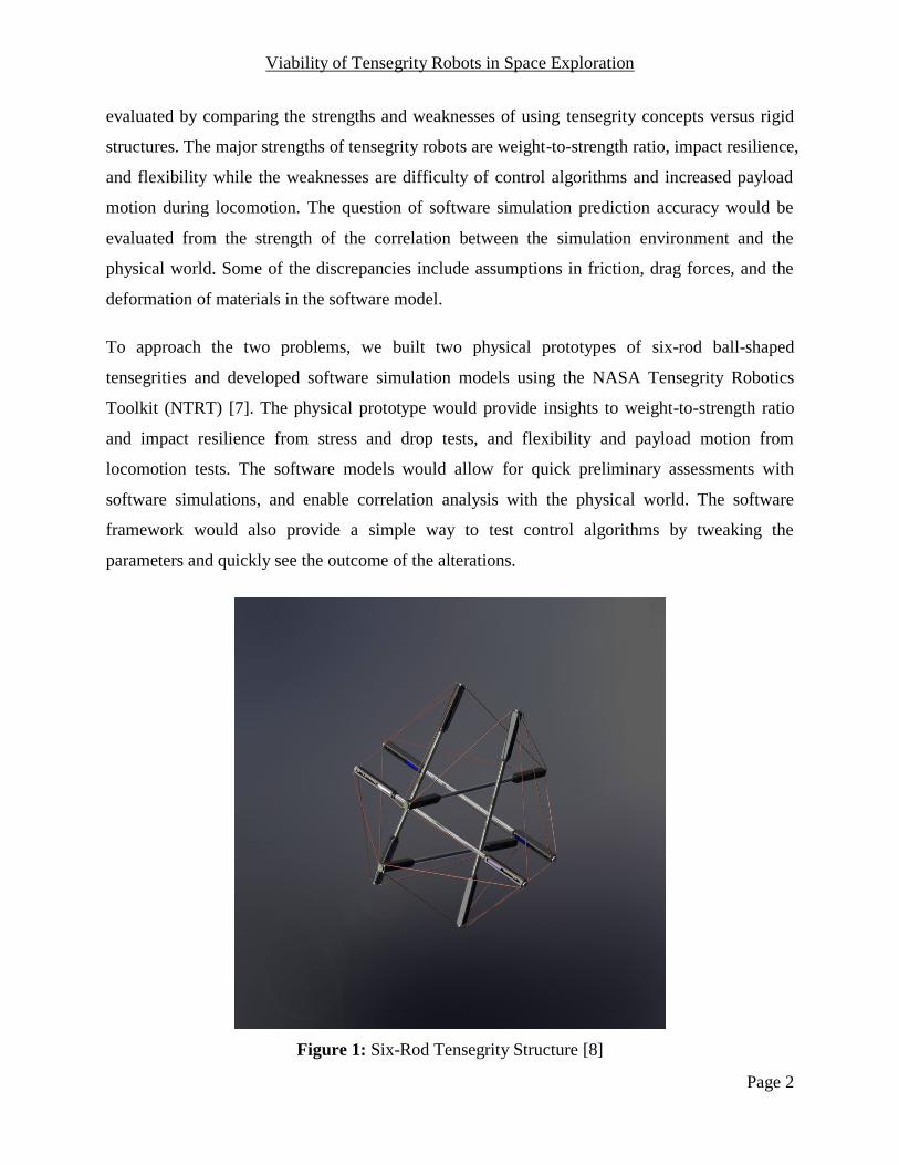
Figure 1: Six-Rod Tensegrity Structure [8]
Viability of Tensegrity Robots in Space Exploration
Page 3
2 Project Overview
The Berkeley Emergent Space Tensegrities (BEST) project was split into three major
components: the design and manufacturing of a single rod in the tensegrity robot prototype for
eventual space exploration, the construction and testing of a six-rod wooden design capable of
rolling motion, and the development of a software simulation package with potential control
algorithms for locomotion. The UC Berkeley Master of Engineering capstone group – Justino
Calangi, Yangxin Chen, Cheng-yu Hong, Yuejia Liu, and Dizhou Lu – focused on the first and
third components and was correspondingly associated into two groups, the Mechatronics Group
and the Controls Group, based on technical expertise of the individual. The second component,
the “Tensegrity Kit”, was developed by graduate mentor Kyunam Kim and the BEST lab
undergraduate team – Terence Cho, Borna Dehghani, Deaho Moon, Laqshya Taneja, and
Aliakbar Toghyan. I will showcase the major deliverables from the Mechatronics Group and the
“Tensegrity Kit” team, but will delve into more detail on the methods and results of the Controls
Group, where I had direct participation.
2.1 Tensegrity Rod Prototype
The “Super Ball Bot” project focused on designing and testing particular elements of a single rod
in the tensegrity structure, which included six rods and twenty-four elastic strings [6]. In the final
prototype, the rods and strings would be assembled in a spherical formation following the six-rod
tensegrity structure (Figure 1). The six-rod tensegrity was chosen as the main robotic structure
for the prototypes and simulations because it is the simplest tensegrity structure capable of
rolling movement.
Our team designed and manufactured several elements of a single rod, such as the battery holder,
the custom connector, and the shock absorber. A close-up of a single rod and the individual
components designed by our team are shown in Figure 2.

Viability of Tensegrity Robots in Space Exploration
Page 4
Figure 2: Single Rod with Components Designed by Capstone Team [9]
The design of each component of the rod included a hand-drawn sketch, several computer-aided
design (CAD) models, and a manufacturing blueprint to specify how to manufacture the
component. Each design went through up to thirty-two iterations based on feedback from
doctorate mentors and mechanical/electrical engineers from NASA. Additionally, the team
rigorously followed the manufacturing design principles and optimized the models based on
numerical analysis from professional software such as Matlab and ANSYS. As a result, the final
product included high-quality designs that were easy to modify and manufacture.
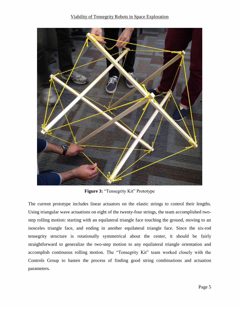
2.2 Six-Rod Tensegrity Kit
Since the design following strict physical and manufacturing standards required substantial
amounts of time even for minor modifications, the BEST team built a simpler prototype using
wooden rods, Firgelli linear actuators, and a LEGO Mindstorms EV3 microcontroller to control
the actuators [10][11]. This design allowed rapid modifications and tests based on the software
simulations. The prototype is illustrated in Figure 3.
Viability of Tensegrity Robots in Space Exploration
Page 5
Figure 3: “Tensegrity Kit” Prototype
The current prototype includes linear actuators on the elastic strings to control their lengths.
Using triangular wave actuations on eight of the twenty-four strings, the team accomplished two-
step rolling motion: starting with an equilateral triangle face touching the ground, moving to an
isosceles triangle face, and ending in another equilateral triangle face. Since the six-rod
tensegrity structure is rotationally symmetrical about the center, it should be fairly
straightforward to generalize the two-step motion to any equilateral triangle orientation and
accomplish continuous rolling motion. The “Tensegrity Kit” team worked closely with the
Controls Group to hasten the process of finding good string combinations and actuation
parameters.
Viability of Tensegrity Robots in Space Exploration
Page 6
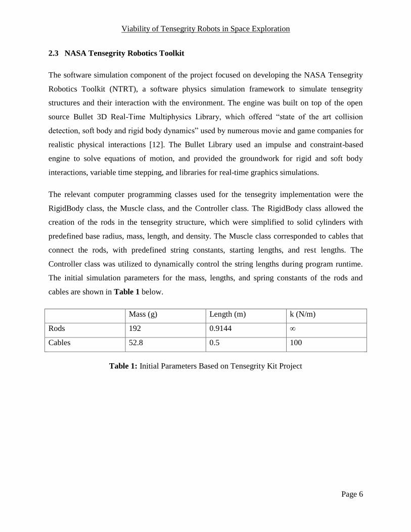
2.3 NASA Tensegrity Robotics Toolkit
The software simulation component of the project focused on developing the NASA Tensegrity
Robotics Toolkit (NTRT), a software physics simulation framework to simulate tensegrity
structures and their interaction with the environment. The engine was built on top of the open
source Bullet 3D Real-Time Multiphysics Library, which offered “state of the art collision
detection, soft body and rigid body dynamics” used by numerous movie and game companies for
realistic physical interactions [12]. The Bullet Library used an impulse and constraint-based
engine to solve equations of motion, and provided the groundwork for rigid and soft body
interactions, variable time stepping, and libraries for real-time graphics simulations.
The relevant computer programming classes used for the tensegrity implementation were the
RigidBody class, the Muscle class, and the Controller class. The RigidBody class allowed the
creation of the rods in the tensegrity structure, which were simplified to solid cylinders with
predefined base radius, mass, length, and density. The Muscle class corresponded to cables that
connect the rods, with predefined string constants, starting lengths, and rest lengths. The
Controller class was utilized to dynamically control the string lengths during program runtime.
The initial simulation parameters for the mass, lengths, and spring constants of the rods and
cables are shown in Table 1 below.
Mass (g) Length (m) k (N/m)
Rods 192 0.9144 ∞
Cables 52.8 0.5 100
Table 1: Initial Parameters Based on Tensegrity Kit Project

Viability of Tensegrity Robots in Space Exploration
Page 7
3 Methods and Results
3.1 Tensegrity Initialization
One issue with the previous framework was the code complexity involved in creating a new
tensegrity structure in the program with a specified size and position. In order to create a simple
six-rod tensegrity, the programmer had to manually find the three-dimensional coordinates for
both ends of each of the six rods, which added up to thirty-six input parameters to calculate. The
initialization procedure was greatly simplified by using the symmetry in the tensegrity structure.
The new framework reduced the amount of input parameters to four: the three-dimensional
coordinates of the center of mass and the radius of the tensegrity structure from the center to the
end of a rod (Figure 4).
Figure 4: Initialized Six-rod Spherical Tensegrity
Although the new framework allowed less fine-grain tuning, it kept the parameters that were
most frequently changed and significantly reduced the time needed to program a working
simulation. It also lessened the amount of time required for the structure to reach equilibrium at
the beginning of the simulations, since the computed rod and cable lengths from the radius are
Viability of Tensegrity Robots in Space Exploration
Page 8
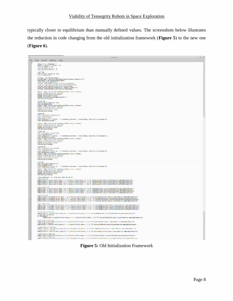
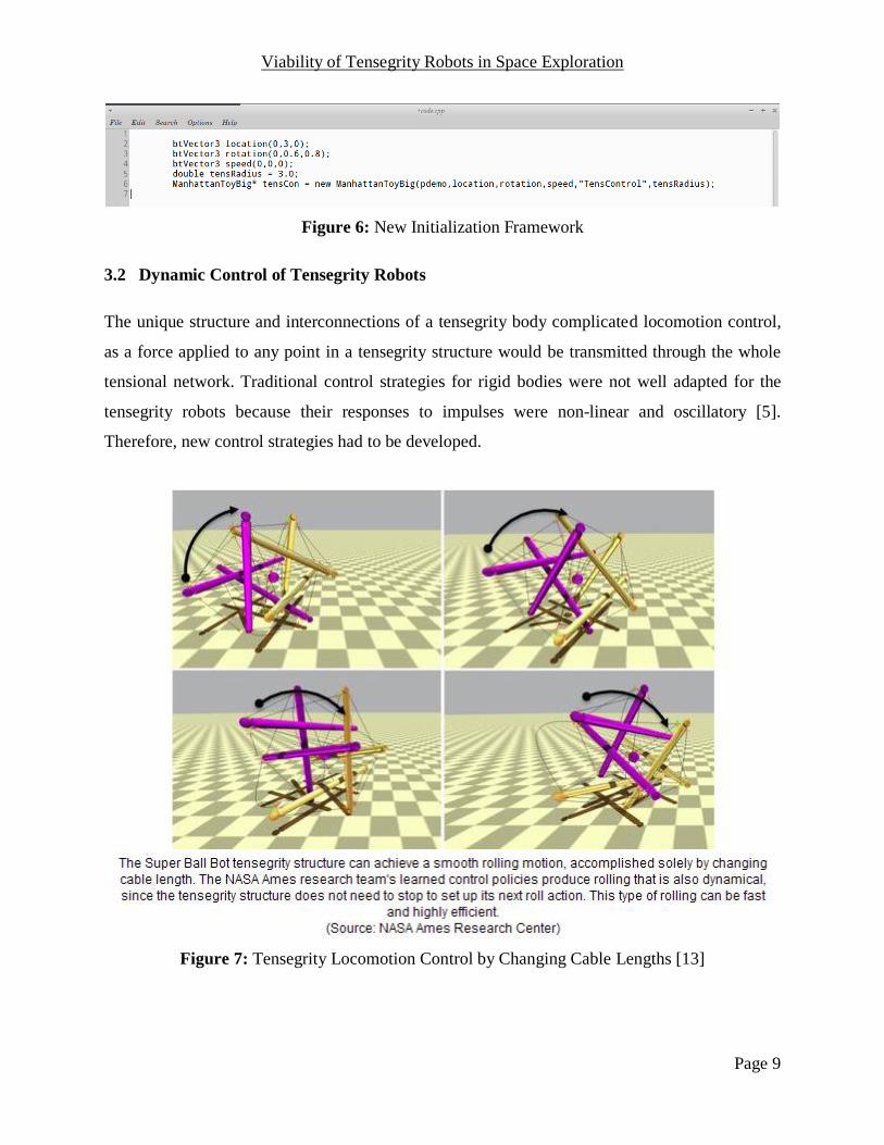
typically closer to equilibrium than manually defined values. The screenshots below illustrates
the reduction in code changing from the old initialization framework (Figure 5) to the new one
(Figure 6).
Figure 5: Old Initialization Framework
Viability of Tensegrity Robots in Space Exploration
Page 9
Figure 6: New Initialization Framework
3.2 Dynamic Control of Tensegrity Robots
The unique structure and interconnections of a tensegrity body complicated locomotion control,
as a force applied to any point in a tensegrity structure would be transmitted through the whole
tensional network. Traditional control strategies for rigid bodies were not well adapted for the
tensegrity robots because their responses to impulses were non-linear and oscillatory [5].
Therefore, new control strategies had to be developed.
Figure 7: Tensegrity Locomotion Control by Changing Cable Lengths [13]

Viability of Tensegrity Robots in Space Exploration
Page 10
The main goal for locomotion control is to move the tensegrity robot via internal forces from
actuators within the structure, without aid from and sometimes even counter to external forces
such as gravity. An intuitive and mechanically viable way to accomplish this task is to shift the
center of mass by expanding and contracting cables or rods within the tensegrity, thus pushing
the robot to fall in the desired direction. In regards to the physical prototypes, it is easier to
implement actuators that shift the lengths of the soft cables rather than the rigid rods. Since two
major goals of the simulations are to replicate observations from the physical robots and suggest
potential actuation strategies, the software simulations mainly focus on cable actuations similar
to those in the “Tensegrity Kit” physical prototype.
The past approach in simulation was to use a machine learning strategy to maximize the distance
traveled by the tensegrity robot. The open-loop control policy was based on sinusoidal actuators
controlling the rest length l of the springs based on the function l(t) = Asin(wt + Φ) + l0, where A,
w, Φ, and l0 were coevolved within an evolutionary framework [14]. Although this approach was
capable of learning a rolling gait after around 10,000 learning iterations, the resulting control
algorithm was difficult to replicate in the physical prototype and even other simulation
frameworks using rigorous mathematical approaches [15]. The actuators also could not be
dynamically modified with parameter inputs during simulation to fine-tune the effects.
We developed a framework to allow for dynamic control of actuation parameters during
simulation runtime. Since actuators in the physical world do not match given control signals
instantaneously, a basic position control loop was implemented to simulate the delay between
receiving the control signal and moving the motor to the desired position. Given the desired
length of a single string, the string would expand or contract based on a predefined motor speed
and the amount of time passed. The equation is shown below (Li+1 = length at next timestep, Li =
length at current timestep, Ld = desired length, M = motor speed, dt = change in time):
Li+1 = Li + sign(Ld – Li)*M*dt
As shown in the equation, the actual length of a cable at a particular timestep (Li) is not
necessarily equivalent to the desired length of the cable (Ld). This is an attempt to simulate
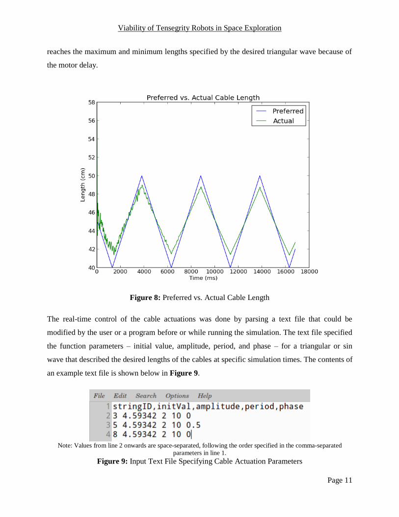
actuation behavior in the real world. The graph in Figure 8 illustrates how the desired and actual
lengths resemble each other but do not perfectly match up. In particular, the actual length never
Viability of Tensegrity Robots in Space Exploration
Page 11
reaches the maximum and minimum lengths specified by the desired triangular wave because of
the motor delay.
Figure 8: Preferred vs. Actual Cable Length
The real-time control of the cable actuations was done by parsing a text file that could be
modified by the user or a program before or while running the simulation. The text file specified
the function parameters – initial value, amplitude, period, and phase – for a triangular or sin
wave that described the desired lengths of the cables at specific simulation times. The contents of
an example text file is shown below in Figure 9.
Note: Values from line 2 onwards are space-separated, following the order specified in the comma-separated
parameters in line 1.
Figure 9: Input Text File Specifying Cable Actuation Parameters
Viability of Tensegrity Robots in Space Exploration
Page 12
3.3 Tensegrity Rolling Using Three-String Actuation
Using the above controls framework, the effects of tuning various string actuation parameters
were observed in simulation. In particular, the simulation model realized rolling locomotion by
actuating only three of the twenty-four cables at any given timeframe. Three cable actuation
stemmed from the idea to actuate as few actuators as possible and still accomplish rolling
movement so power consumption is minimized. One and two cable actuations were also
attempted in simulation; however, the robot did not show promising movement without
significant actuation speed and power not available in the current physical motors.
To figure out the optimal combination of three cables, the simulation was run with all possible
three-string combinations using triangular wave actuation parameters similar to that of the linear
actuators in the “Tensegrity Kit” physical prototype. The exact parameters were an initial value
of 50 centimeters, amplitude of 20 centimeters, and period of 10 seconds. In addition, the phases
of the triangular waves were also methodologically altered. For each combination of three-
strings, four simulations were run: one with phases in sync and three with one of the string
actuations in antiphase (one wave is at the maximum amplitude when the other waves are at the
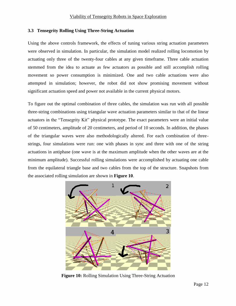
minimum amplitude). Successful rolling simulations were accomplished by actuating one cable
from the equilateral triangle base and two cables from the top of the structure. Snapshots from
the associated rolling simulation are shown in Figure 10.
Figure 10: Rolling Simulation Using Three-String Actuation
Viability of Tensegrity Robots in Space Exploration
Page 13
3.4 Physical Prototype Tests – Nine and Five-String Actuations
With the simulation framework described above, our team tested various control strategies and
compared the results with the “Tensegrity Kit” physical prototype to confirm their validity. A
physical six-rod tensegrity prototype built using wooden rods was actuated by contracting a
subset of the twenty-four linear actuators controlling the lengths of the strings. The three-cable
control strategy that succeeded in the software simulation did not produce enough momentum to
produce rolling movement in the physical prototype. Therefore, a new control strategy that
actuated nine cables was proposed to increase the shift in center of mass and move the robot.
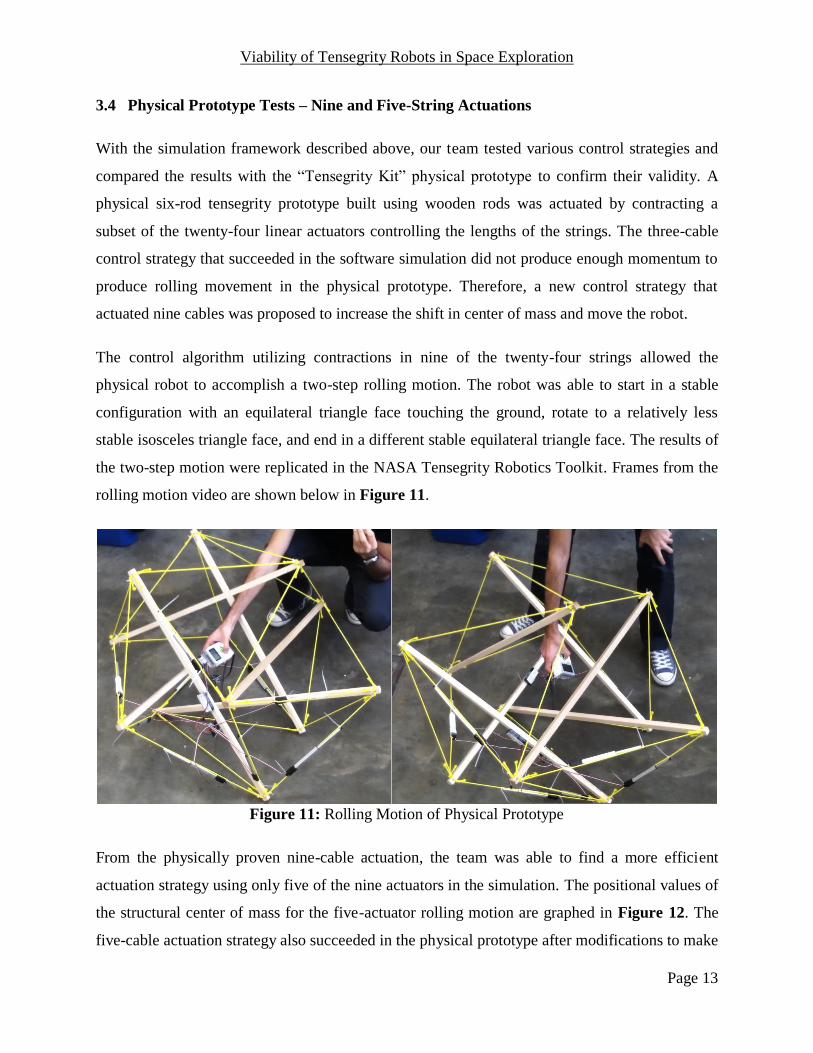
The control algorithm utilizing contractions in nine of the twenty-four strings allowed the
physical robot to accomplish a two-step rolling motion. The robot was able to start in a stable
configuration with an equilateral triangle face touching the ground, rotate to a relatively less
stable isosceles triangle face, and end in a different stable equilateral triangle face. The results of
the two-step motion were replicated in the NASA Tensegrity Robotics Toolkit. Frames from the
rolling motion video are shown below in Figure 11.
Figure 11: Rolling Motion of Physical Prototype
From the physically proven nine-cable actuation, the team was able to find a more efficient
actuation strategy using only five of the nine actuators in the simulation. The positional values of
the structural center of mass for the five-actuator rolling motion are graphed in Figure 12. The
five-cable actuation strategy also succeeded in the physical prototype after modifications to make

Viability of Tensegrity Robots in Space Exploration
Page 14
the linear actuators more effective. Furthermore, by using the symmetry in the tensegrity
structure, we were able to implement continuous rolling motion in the software simulation [16].
Figure 12: Center of Mass Position for Five Actuator Two-Step Motion
Viability of Tensegrity Robots in Space Exploration
Page 15
4 Discussion
4.1 Physical Prototype and Simulation Differences
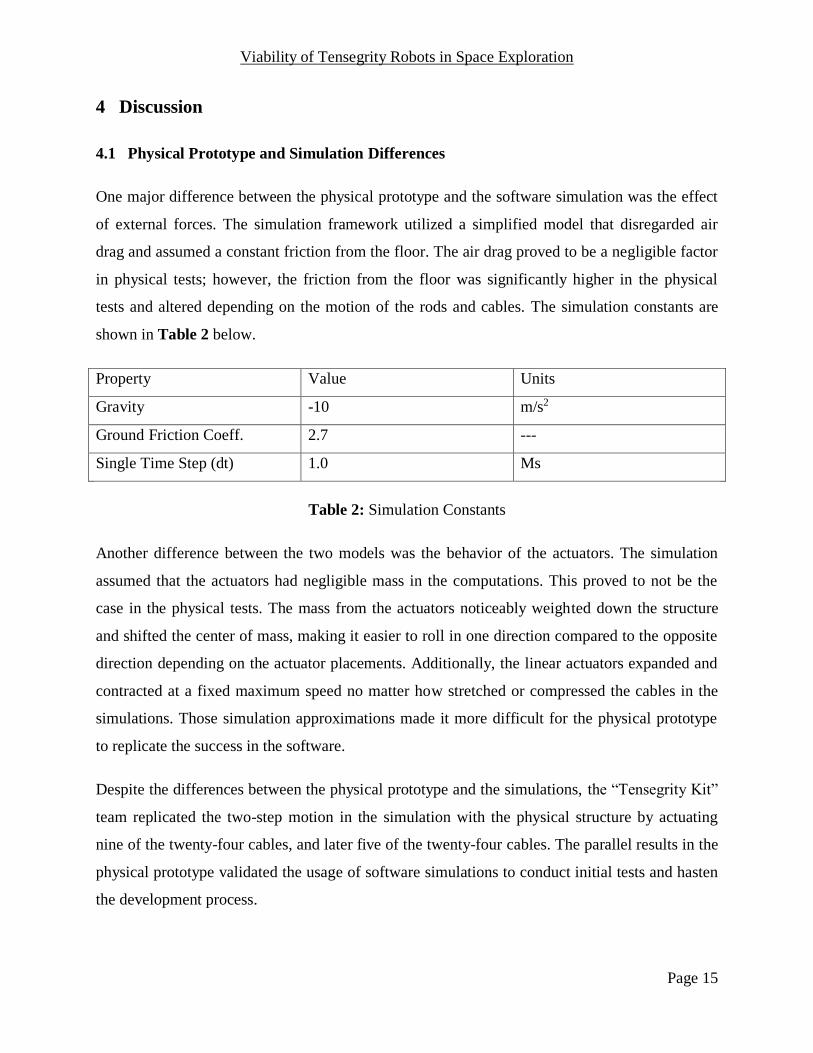
One major difference between the physical prototype and the software simulation was the effect
of external forces. The simulation framework utilized a simplified model that disregarded air
drag and assumed a constant friction from the floor. The air drag proved to be a negligible factor
in physical tests; however, the friction from the floor was significantly higher in the physical
tests and altered depending on the motion of the rods and cables. The simulation constants are
shown in Table 2 below.
Property Value Units
Gravity -10 m/s2
Ground Friction Coeff. 2.7 ---
Single Time Step (dt) 1.0 Ms
Table 2: Simulation Constants
Another difference between the two models was the behavior of the actuators. The simulation
assumed that the actuators had negligible mass in the computations. This proved to not be the
case in the physical tests. The mass from the actuators noticeably weighted down the structure
and shifted the center of mass, making it easier to roll in one direction compared to the opposite
direction depending on the actuator placements. Additionally, the linear actuators expanded and
contracted at a fixed maximum speed no matter how stretched or compressed the cables in the
simulations. Those simulation approximations made it more difficult for the physical prototype
to replicate the success in the software.
Despite the differences between the physical prototype and the simulations, the “Tensegrity Kit”
team replicated the two-step motion in the simulation with the physical structure by actuating
nine of the twenty-four cables, and later five of the twenty-four cables. The parallel results in the
physical prototype validated the usage of software simulations to conduct initial tests and hasten
the development process.
Viability of Tensegrity Robots in Space Exploration
Page 16
However, the physical prototype actuated five cables to accomplish the same motion as actuating
three cables in the simulation. Furthermore, the tensegrity prototype was never able to
accomplish continuous rolling locomotion by merely controlling the lengths of five cables as in
the software simulation. Nevertheless, the capacity for the physical structure to move at all was a
promising beginning for more complex locomotion of the tensegrity structure.
4.2 Software Simulation Robustness for Tensegrity
Previous work on control for tensegrity robots utilized evolutionary algorithms to “learn” the
actuation parameters. Atil Iscen et al. [14], Ken Caluwaerts et al. [17] and Chandana Paul et al.
[18] had all developed evolutionary algorithms that successfully simulated robust rolling motion
in software. Atil Iscen et al. used “an open-loop control policy based on sinusoidal actuators
coevolved in order to maximize the distance traveled by the tensegrity robot” [5]. Ken
Caluwaerts et al. proposed “a closed-loop control strategy based on reservoir computing […] to
generate [signals] using a central pattern generator (CPG) and evolve parameters of a neural
network” [5].
However, control strategies developed by evolutionary algorithms were complicated to realize in
physical structures, since the actuation parameters might differ greatly for similar motions, such
as rolling left and rolling right, or change multiple times within a second. Consequently, prior
physical prototypes had not been able to replicate the rolling motions in simulation.
A major goal for the Controls Group was to accomplish the same movements using simpler
motions that could be easily realized in a linear actuator. We had not yet reached the goal of
continuous rolling motion in the physical prototype. However, the two-step rolling motion we
did accomplish proved the viability of moving the tensegrity robot with simple linear string
actuations.
For the most part, software simulations were consistent with the physical tests on tensegrity
dynamic motion. However, there were instances when the tensegrity model in simulation would
vibrate without any visible forces. This could be a software bug in the simulation program, and
we are currently attempting to fix the issue.
Viability of Tensegrity Robots in Space Exploration
Page 17
There were also simulation behaviors that were difficult or impossible to replicate in the physical
prototype. For instance, the software tensegrity model would break apart when a combination of
strings were stretched beyond four times their original rest length. However, the motors in the
physical prototype could not apply enough force to replicate the behavior.
Despite the shortcomings of software simulation to exactly replicate the physical environment, it
approximates real-world interactions well enough to provide useful preliminary analysis.
Simulations were also valuable in providing initial actuation parameters to test. Additionally,
physical locations that are impractical to do prototype tests, such as the environment on Titan,
can be simulated in software.

Viability of Tensegrity Robots in Space Exploration
Page 18
5 Conclusion
This capstone project provided initial assessments on the viability of developing and controlling
tensegrity robots for use in extraterrestrial exploration. The single-rod physical prototype
designed by the Mechatronics Group proved the manufacturing viability and impact resilience of
the tensegrity structure. The six-rod wooden prototype illustrated the viability of moving the
tensegrity robot with linear actuators. The software simulation results provided support for the
capability of continuous rolling motion on both Earth and Titan.
In respect to space exploration, the research combining tensegrity and robotics is still in its
infancy stages. As mentioned in this report, progress is still being made for rolling locomotion of
a physical prototype on a flat surface under Earth’s gravity. The NASA team working on the
development projects eight more years of research, design, and tests before the product is ready
for the launch to Titan.
Software simulations of the robot experienced greater success in rolling locomotion. However,
further developments are required to produce control strategies that can be implemented in a
physical prototype. Control algorithms for other tensegrity motions, such as compression and
bouncing, are also works in progress for the simulation. The NASA Tensegrity Robotics Toolkit
also has the capability to change the material properties of the rods and cables, which can be
further explored to produce the optimal movements.
Tensegrity robots have so far proved to be promising replacements to rigid robots based on the
initial research and prototypes. The reduced weight and increased flexibility and impact
resilience from using the tensegrity structure suggest exciting potential in the future of robotics
and extraterrestrial exploration.
Viability of Tensegrity Robots in Space Exploration
Page 19
6 References
[1] Richard Buckminster Fuller. Guinea Pig B: The 56 Year Experiment. Critical Path Publishing.
(2004, March).
[2] Mike Wall. “How Does the Curiosity Mars Rover Preserve Its Wheels? By Driving
Backwards, Of Course.” The Christian Science Monitor. (2014, Feb. 21). [Online]. Available:
http://www.csmonitor.com/Science/2014/0221/How-does-the-Curiosity-Mars-rover-preserve-its-
wheels-By-driving-backward-of-course
[3] Mizuho Shibata and Shinichi Hirai. “Rolling Locomotion of Deformable Tensegrity
Structure.” Department of Robotics, Ritsumeikan University. (2009, May 12).
[4] “IcoTens.” Cornell Creative Machines Lab. [Online]. Available:
http://creativemachines.cornell.edu/icotens
[5] Jérémie Despraz. “Super Ball Bot – Structures for Planetary Landing and Exploration.”
NASA Ames Research Center – Intelligent Robotics Group. (2013, Aug. 16).
[6] “SuperBall Bot Tensegrity Planetary Lander.” National Aeronautics and Space
Administration. (2012). [Online]. Available: http://ti.arc.nasa.gov/tech/asr/intelligent-
robotics/tensegrity/superballbot/
[7] “Dynamic Tensegrity Robotics.” National Aeronautics and Space Administration. (2012).
[Online]. Available: http://ti.arc.nasa.gov/tech/asr/intelligent-robotics/tensegrity/
[8] Dizhou Lu. “Structural Design for Tensegrity Mechatronics.” Master of Engineering Thesis
from University of California, Berkeley. (2014, Apr. 14).
[9] Yangxin Chen. “Master Thesis Report.” Master of Engineering Thesis from University of
California, Berkeley. (2014, Apr. 14).
[10] “Firgelli L12 Series.” Firgelli Technologies Inc. [Online]. Available:
http://www.firgelli.com/products.php
Viability of Tensegrity Robots in Space Exploration
Page 20
[11] “LEGO Mindstorms EV3 Brick Overview.” LEGO Mindstorms EV3: The Next Generation
in Mindstorms Robotics. [Online]. Available:
http://www.legomindstormsev3.com/?page_id=754
[12] Bullet Physics Library - Project Home. [Online]. Available:
https://code.google.com/p/bullet/
[13] Bob Jackson. “Tensegrity.” Cielotech Online. [Online]. Available:
http://cielotech.wordpress.com/2014/01/25/tensegrity/
[14] Atil Iscen, Adrian Agogino, Vytas SunSpiral, and Kagan Tumer. “Controlling Tensegrity
Robots Through Evolution.” Proceeding of the fifteenth annual conference on Genetic and
evolutionary computation conference. ACM. (2013).
[15] Justino Calangi. “Model-Based Control System for Packing a 6-Bar Tensegrity Structure.”
Master of Engineering Thesis from University of California, Berkeley. (2014, Apr. 14).
[16] “Tensegrity Simulation with 5 Linear Actuators.” (2014, May 1). [Online]. Available:
https://www.youtube.com/watch?v=WwfHruPOYB0
[17] Ken Caluwaerts, Michiel D’Haene, David Verstraeten, and Benjamin Schrauwen.
“Locomotion without a Brain: Physical Reservoir Computing in Tensegrity Structures.”
Artificial Life, 19(1):35-66. (2013).
[18] Chandana Paul, Hod Lipson, and Francisco J. Valero Cuevas. "Evolutionary Form-finding
of Tensegrity Structures." Proceedings of the 2005 conference on Genetic and evolutionary
computation. ACM. (2005).
[19] Vytas SunSpiral, George Gorospe, Jonathan Bruce, Atil Iscen, George Korbel, Sophie
Milam, Adrian Agogino, and David Atkinson. “Tensegrity Based Probes for Planetary
Exploration: Entry, Descent and Landing and Surface Mobility Analysis.” International Journal
of Planetary Probes. (2013, July).
[20] Atil Iscen, et al. "Robust Distributed Control of Rolling Tensegrity Robot." The
Autonomous Robots and Multirobot Systems (ARMS) Workshop at AAMAS. Vol. 2013. 2013.
Viability of Tensegrity Robots in Space Exploration
Page 21
[21] Mark Khazanov, et al. "Exploiting Dynamical Complexity in a Physical Tensegrity Robot to
Achieve Locomotion." Advances in Artificial Life, ECAL. Vol. 12. (2013).
[22] Valter Boehm, et al. "An Approach to Locomotion Systems Based on 3d Tensegrity
Structures with a Minimal Number of Struts." Robotics; Proceedings of ROBOTIK 2012; 7th
German Conference on VDE. (2012).
[23] Adrian Boeing and Thomas Braunl. “Evaluation of Real-time Physics Simulation Systems.”
Proceedings of the 5th international conference on computer graphics and interactive techniques
in Australia and Southeast Asia. Pages 281–288. ACM. (2007).
[24] Jesse van den Kieboom. “Codyn.” [Online]. Available: http://www.codyn.net/
[25] Ken Caluwaerts, Jeremie Despraz, Atil Iscen, Andrew Sabelhaus, Jonathan Bruce, and
Vytas SunSpiral. “Design and Control of Compliant Tensegrity Robots Through Simulation and
Hardware Validation.” Journal of the Royal Society Interface. (2013).
[26] Chandana Paul, Francisco J. Valero-Cuevas, and Hod Lipson. "Design and Control of
Tensegrity Robots for Locomotion." Robotics, IEEE Transactions. Pages 944-957. (2006).
University of California, Berkeley College of Engineering
MASTER OF ENGINEERING - SPRING 2014
Department: Electrical Engineering and Computer Science
Concentration: Visual Computing and Computer Graphics
Thesis: Viability of Tensegrity Robots in Space Exploration
Student Name: Eric Cheng-yu Hong
This Masters Project Paper fulfills the Master of Engineering degree
requirement.
Approved by:
1. Capstone Project Advisor:
Signature: __________________________ Date ____________
Print Name/Department: Alice M. Agogino / ME
2. Faculty Committee Member #2:
Signature: __________________________ Date ____________
Print Name/Department: Edward A. Lee / EECS