Embed Size (px)
Citation preview
VHDL – Dataflow and Structural Modeling and
TestbenchesENGIN 341 – Advanced Digital Design
University of Massachusetts Boston
Department of Engineering
Dr. Filip Cuckov
Overview
1. Introduction to VHDL2. VHDL Language Constructs3. VHDL Testbenches4. Lab 1 – Modular Design and Testbench Simulation5. Generic and Generate Statements6. Dataflow MUX Design7. More on Testbenches
1. Introduction to VDHL
• VDHL: VHSIC Hardware Description Language• VHSIC: Very High Speed Integrated Circuit
• Developed with support from the DoD (US Air Force) in 1981• By Intermetrics, Texas Instruments, and IBM
• Based on ADA• IEEE standard in ‘87,’93,’00,’02, ’07,’08 (VHDL-1987 … VHDL-2008)• HDL used for EDA• Hardware Description Language used for Electronic Design Automation
VHDL - Defined
• Parallel programming language• Concurrent process execution
• Used to model, simulate, and synthesize electronic circuits• At various levels of abstraction• Supports management of hierarchies and incremental design
• A general purpose programming language• This class will focus on synthesizable and simulation subset
• Competitor: Verilog• You will eventually need to learn it
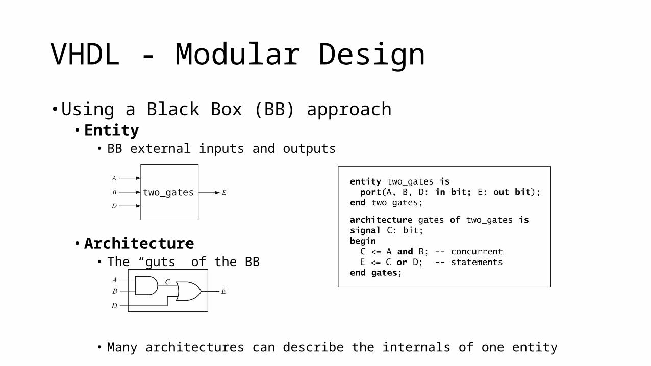
• Using a Black Box (BB) approach• Entity
• BB external inputs and outputs
• Architecture• The “guts” of the BB
• Many architectures can describe the internals of one entity
VHDL - Modular Design
two_gates
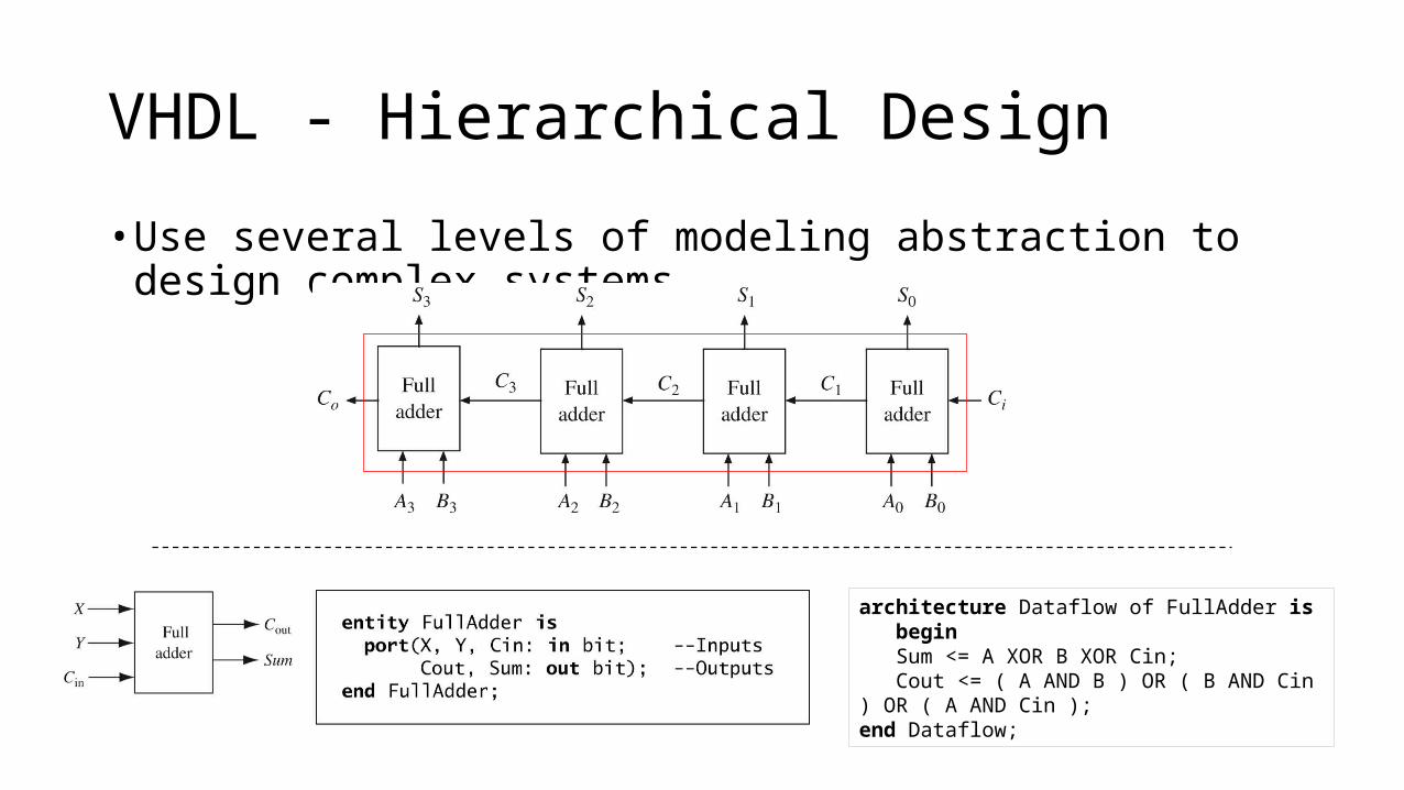
• Use several levels of modeling abstraction to design complex systems
VHDL - Hierarchical Design
architecture Dataflow of FullAdder is begin Sum <= A XOR B XOR Cin; Cout <= ( A AND B ) OR ( B AND Cin ) OR ( A AND Cin );end Dataflow;
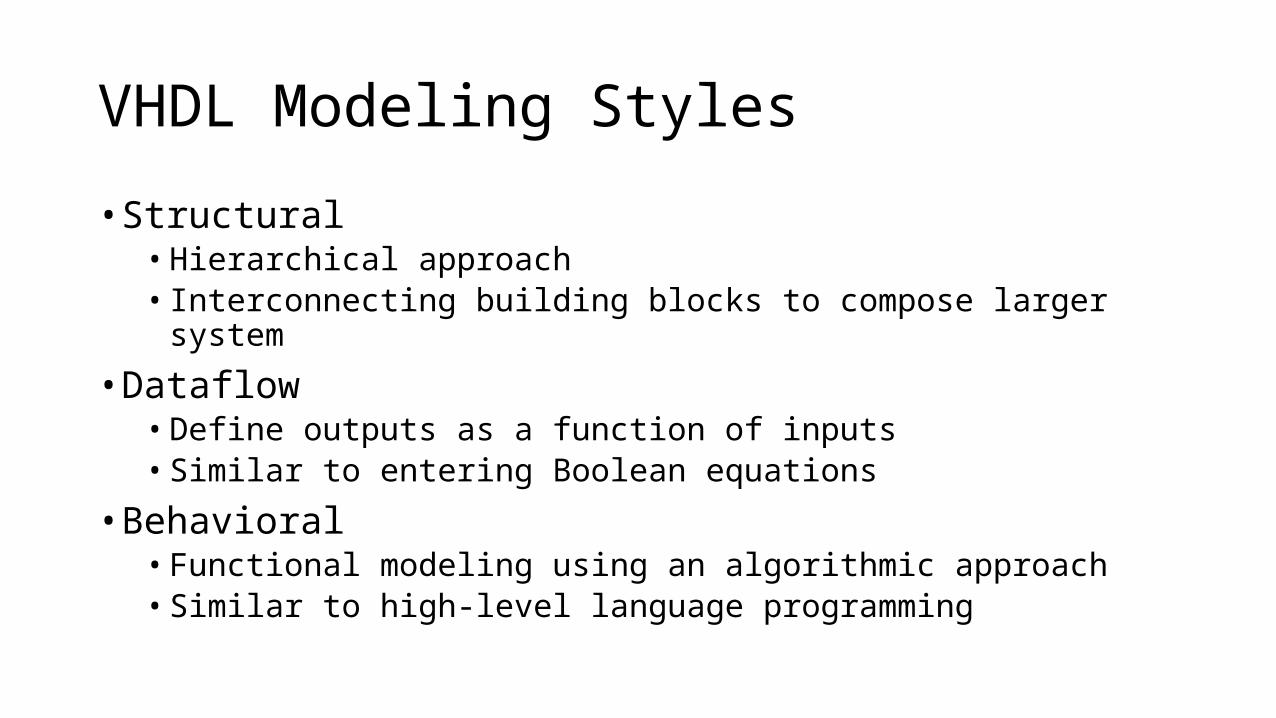
VHDL Modeling Styles
• Structural• Hierarchical approach• Interconnecting building blocks to compose larger system
• Dataflow• Define outputs as a function of inputs• Similar to entering Boolean equations
• Behavioral• Functional modeling using an algorithmic approach• Similar to high-level language programming
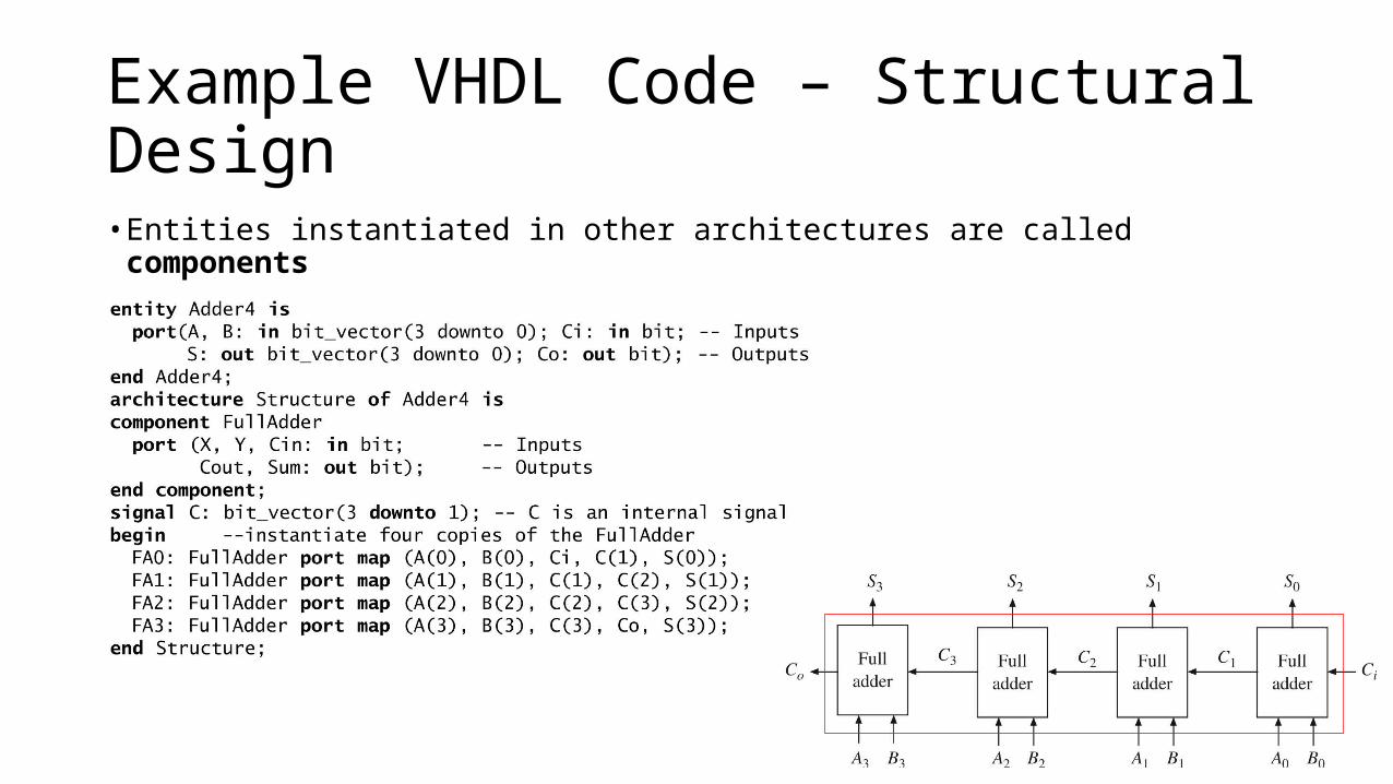
Example VHDL Code – Structural Design • Entities instantiated in other architectures are called components
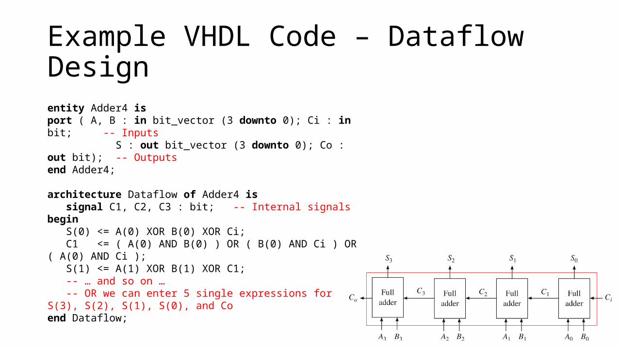
Example VHDL Code – Dataflow Design entity Adder4 isport ( A, B : in bit_vector (3 downto 0); Ci : in bit; -- Inputs S : out bit_vector (3 downto 0); Co : out bit); -- Outputsend Adder4;
architecture Dataflow of Adder4 is signal C1, C2, C3 : bit; -- Internal signalsbegin S(0) <= A(0) XOR B(0) XOR Ci; C1 <= ( A(0) AND B(0) ) OR ( B(0) AND Ci ) OR ( A(0) AND Ci ); S(1) <= A(1) XOR B(1) XOR C1; -- … and so on … -- OR we can enter 5 single expressions for S(3), S(2), S(1), S(0), and Coend Dataflow;
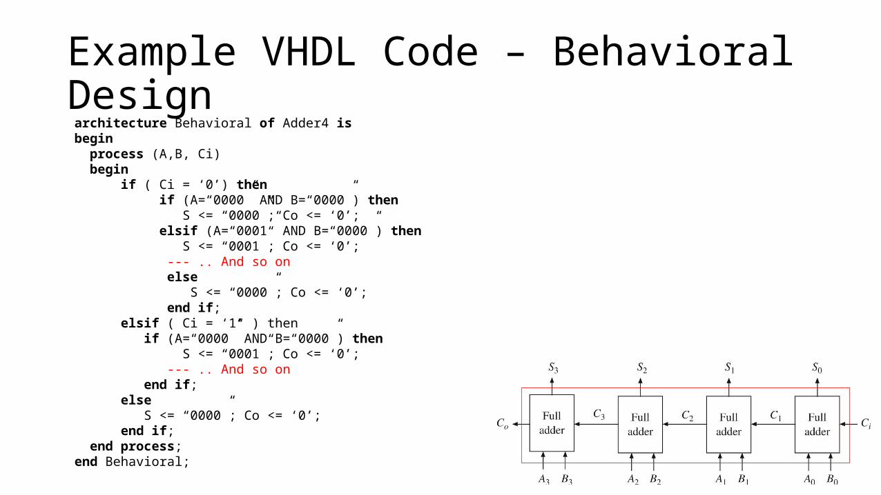
Example VHDL Code – Behavioral Design
architecture Behavioral of Adder4 isbegin process (A,B, Ci) begin if ( Ci = ‘0’) then if (A=“0000” AND B=“0000”) then S <= “0000”; Co <= ‘0’; elsif (A=“0001” AND B=“0000”) then S <= “0001”; Co <= ‘0’; --- .. And so on else S <= “0000”; Co <= ‘0’; end if; elsif ( Ci = ‘1’ ) then if (A=“0000” AND B=“0000”) then S <= “0001”; Co <= ‘0’; --- .. And so on end if; else S <= “0000”; Co <= ‘0’; end if; end process;end Behavioral;
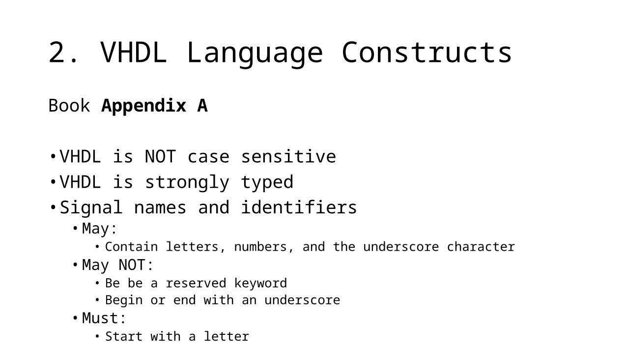
2. VHDL Language Constructs
Book Appendix A
• VHDL is NOT case sensitive• VHDL is strongly typed• Signal names and identifiers• May:
• Contain letters, numbers, and the underscore character• May NOT:
• Be be a reserved keyword• Begin or end with an underscore
• Must:• Start with a letter
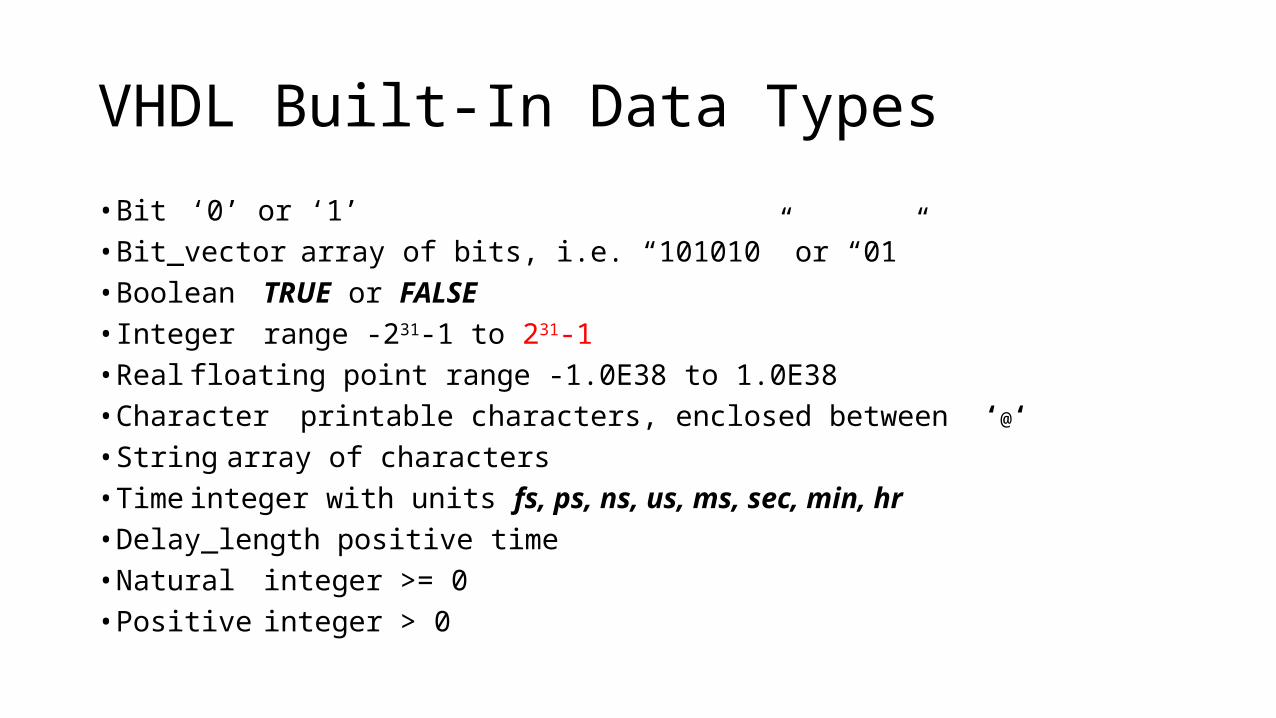
VHDL Built-In Data Types
• Bit ‘0’ or ‘1’• Bit_vector array of bits, i.e. “101010” or “01”• Boolean TRUE or FALSE• Integer range -231-1 to 231-1• Real floating point range -1.0E38 to 1.0E38• Character printable characters, enclosed between ‘@‘• String array of characters• Time integer with units fs, ps, ns, us, ms, sec, min, hr• Delay_length positive time• Natural integer >= 0• Positive integer > 0
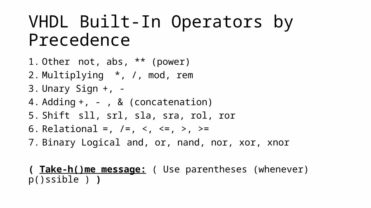
VHDL Built-In Operators by Precedence1. Other not, abs, ** (power)2. Multiplying *, /, mod, rem3. Unary Sign +, -4. Adding +, - , & (concatenation)5. Shift sll, srl, sla, sra, rol, ror6. Relational =, /=, <, <=, >, >=7. Binary Logical and, or, nand, nor, xor, xnor
( Take-h()me message: ( Use parentheses (whenever) p()ssible ) )
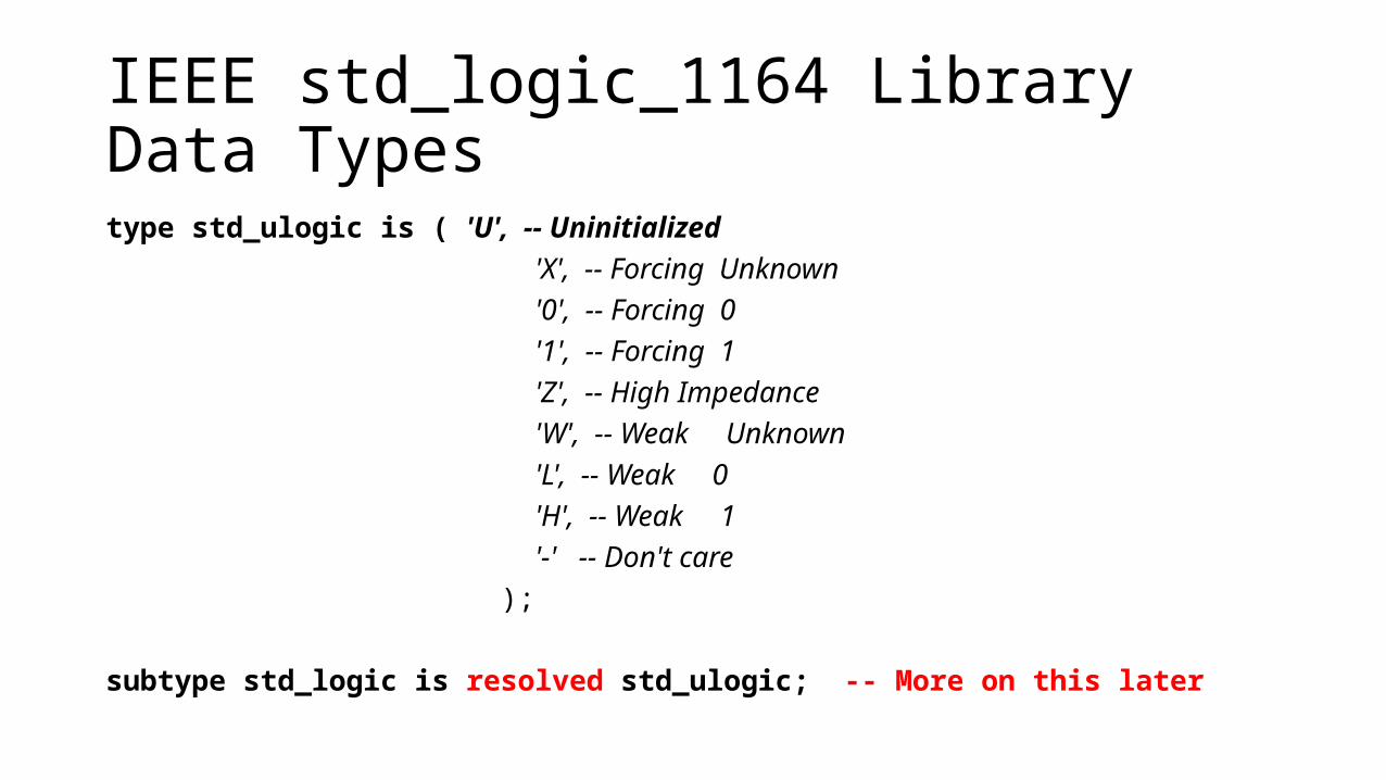
IEEE std_logic_1164 Library Data Typestype std_ulogic is ( 'U', -- Uninitialized 'X', -- Forcing Unknown '0', -- Forcing 0 '1', -- Forcing 1 'Z', -- High Impedance 'W', -- Weak Unknown 'L', -- Weak 0 'H', -- Weak 1 '-' -- Don't care );
subtype std_logic is resolved std_ulogic; -- More on this later
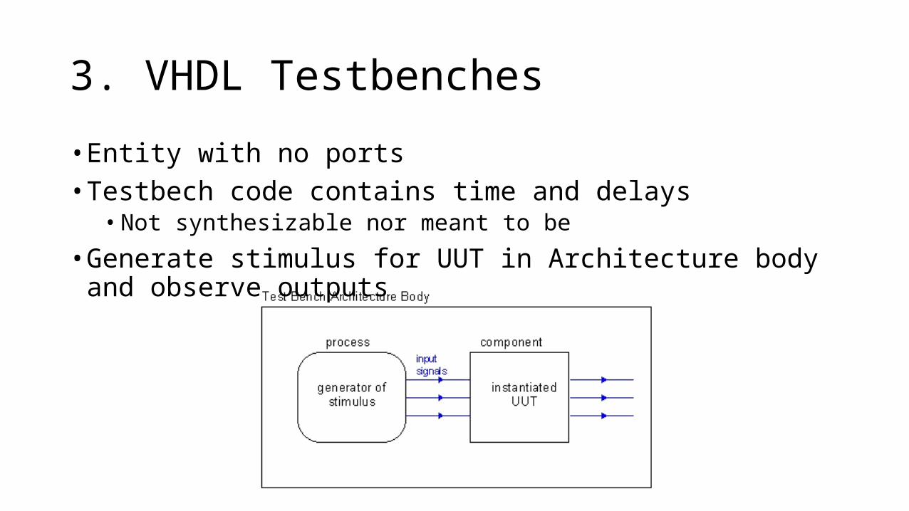
3. VHDL Testbenches
• Entity with no ports• Testbech code contains time and delays• Not synthesizable nor meant to be
• Generate stimulus for UUT in Architecture body and observe outputs
4. Lab 1- Modular Design and Testbenches• Let’s practice
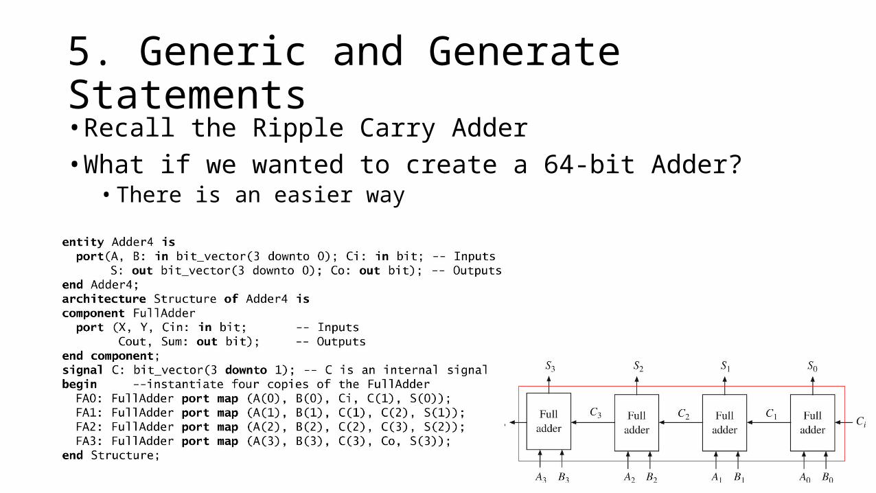
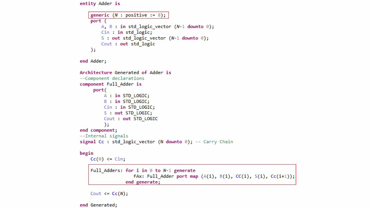
5. Generic and Generate Statements• Recall the Ripple Carry Adder• What if we wanted to create a 64-bit Adder? • There is an easier way
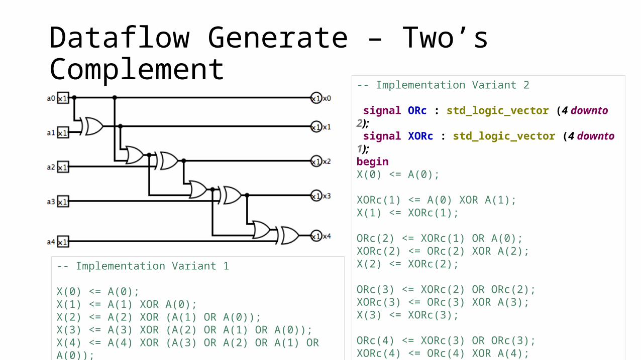
Dataflow Generate – Two’s Complement
-- Implementation Variant 1
X(0) <= A(0);X(1) <= A(1) XOR A(0);X(2) <= A(2) XOR (A(1) OR A(0));X(3) <= A(3) XOR (A(2) OR A(1) OR A(0));X(4) <= A(4) XOR (A(3) OR A(2) OR A(1) OR A(0));
-- Implementation Variant 2
signal ORc : std_logic_vector (4 downto 2); signal XORc : std_logic_vector (4 downto 1); beginX(0) <= A(0);
XORc(1) <= A(0) XOR A(1);X(1) <= XORc(1);
ORc(2) <= XORc(1) OR A(0);XORc(2) <= ORc(2) XOR A(2);X(2) <= XORc(2);
ORc(3) <= XORc(2) OR ORc(2);XORc(3) <= ORc(3) XOR A(3);X(3) <= XORc(3);
ORc(4) <= XORc(3) OR ORc(3);XORc(4) <= ORc(4) XOR A(4);X(4) <= XORc(4);
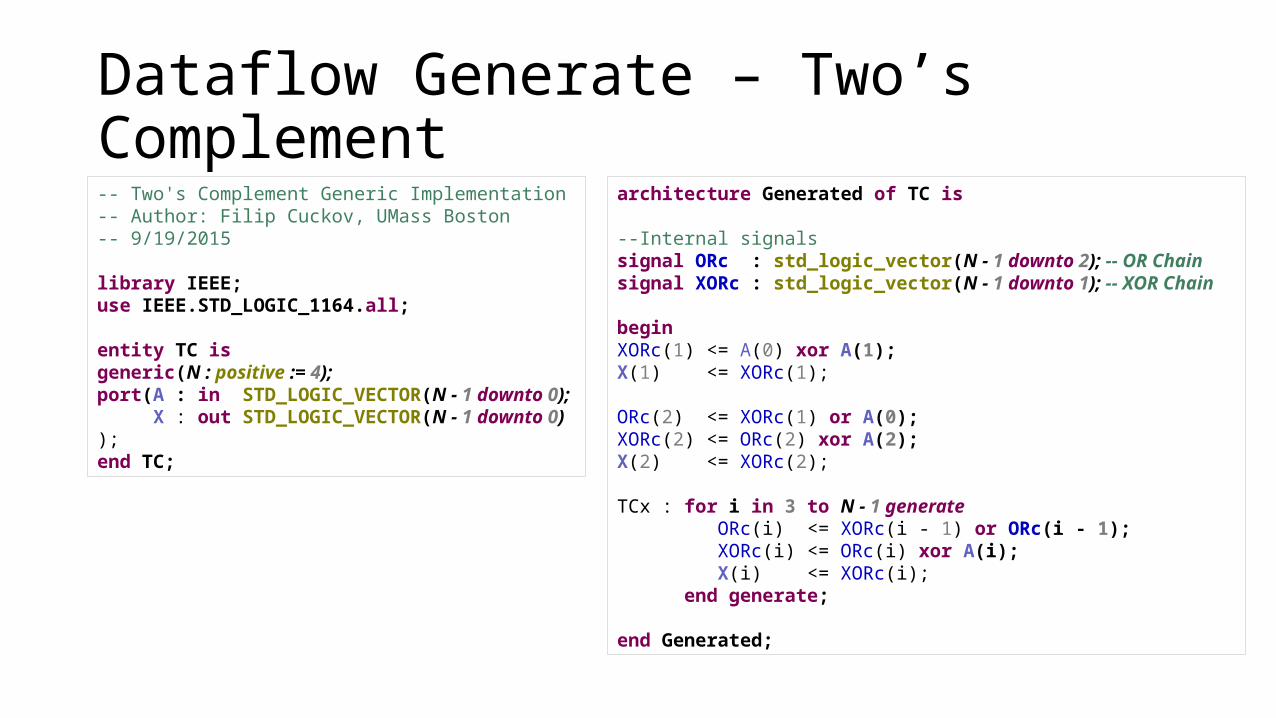
Dataflow Generate – Two’s Complement
architecture Generated of TC is
--Internal signalssignal ORc : std_logic_vector(N - 1 downto 2); -- OR Chain signal XORc : std_logic_vector(N - 1 downto 1); -- XOR Chain
beginXORc(1) <= A(0) xor A(1);X(1) <= XORc(1);
ORc(2) <= XORc(1) or A(0);XORc(2) <= ORc(2) xor A(2);X(2) <= XORc(2);
TCx : for i in 3 to N - 1 generate ORc(i) <= XORc(i - 1) or ORc(i - 1); XORc(i) <= ORc(i) xor A(i); X(i) <= XORc(i); end generate;
end Generated;
-- Two's Complement Generic Implementation-- Author: Filip Cuckov, UMass Boston-- 9/19/2015
library IEEE;use IEEE.STD_LOGIC_1164.all;
entity TC isgeneric(N : positive := 4);port(A : in STD_LOGIC_VECTOR(N - 1 downto 0); X : out STD_LOGIC_VECTOR(N - 1 downto 0));end TC;
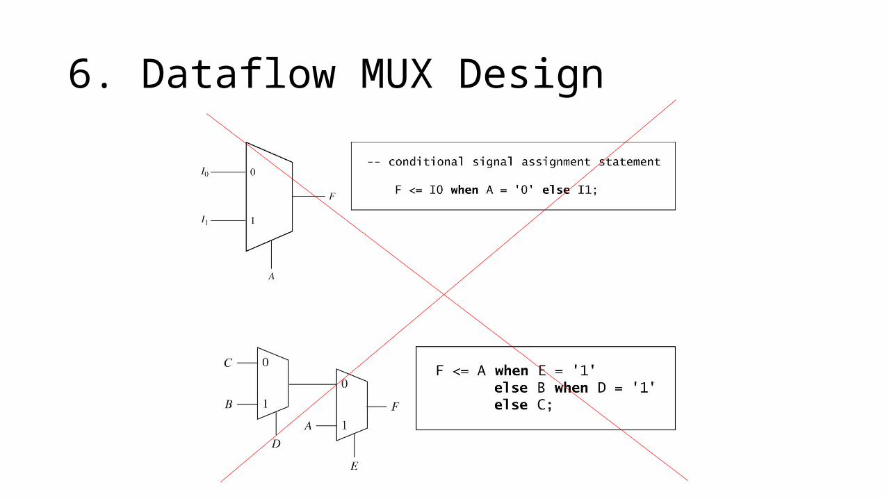
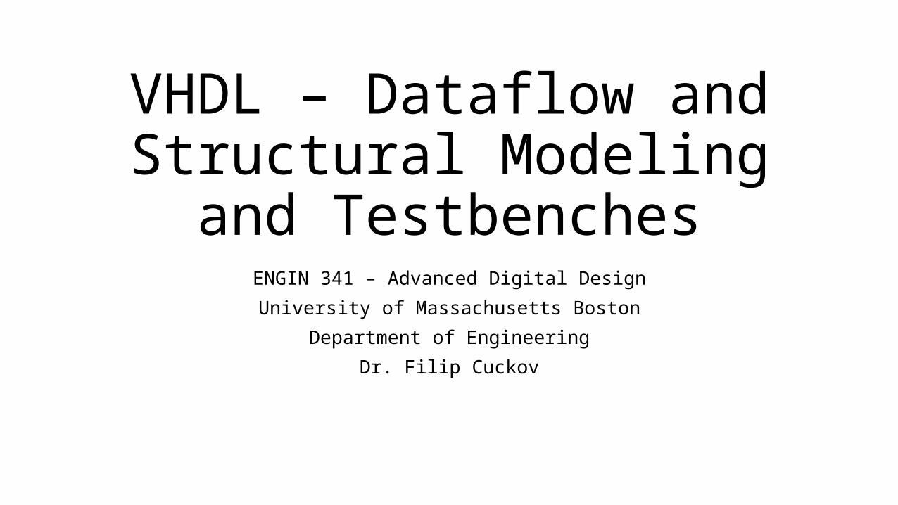
6. Dataflow MUX Design
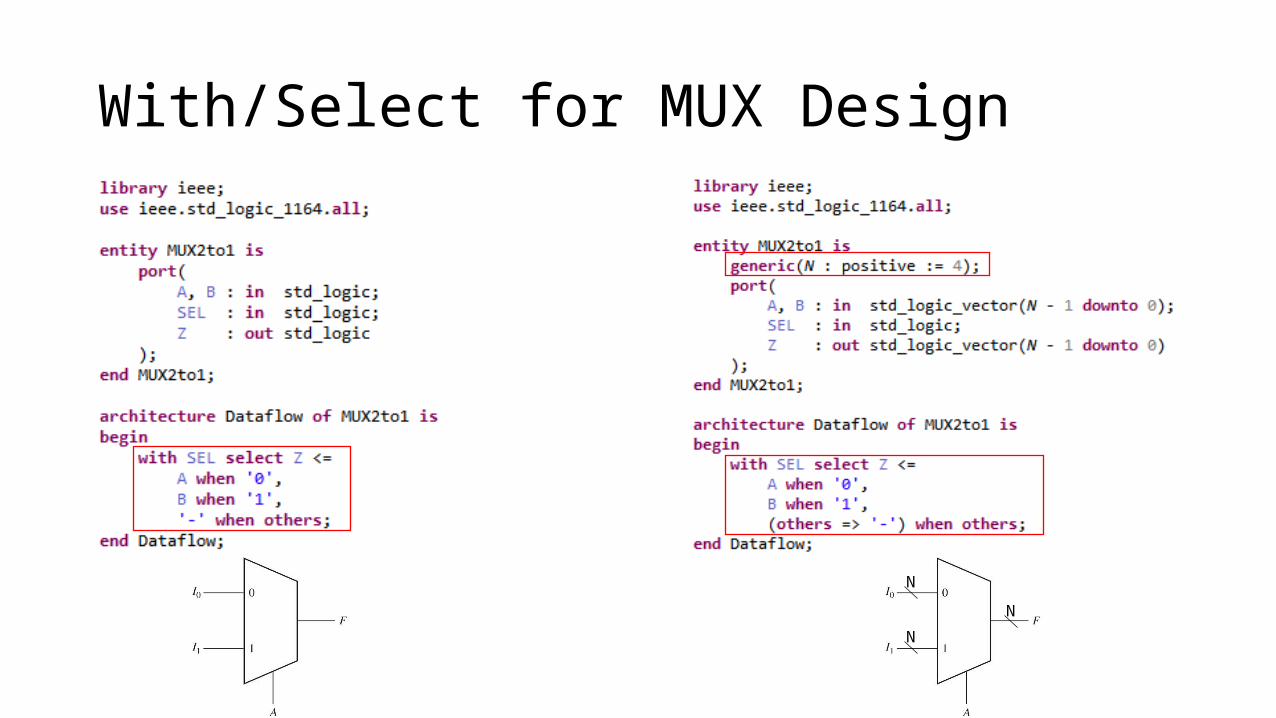
With/Select for MUX Design
N
N
N
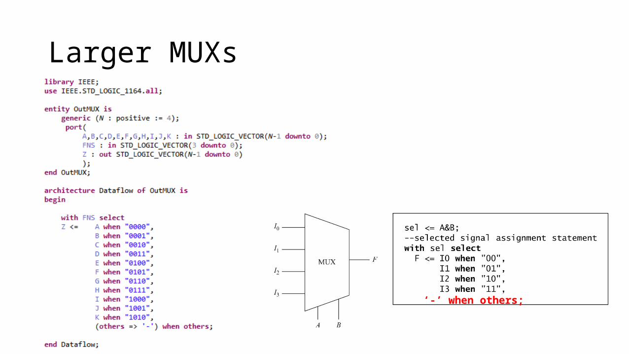
Larger MUXs
‘-’ when others;
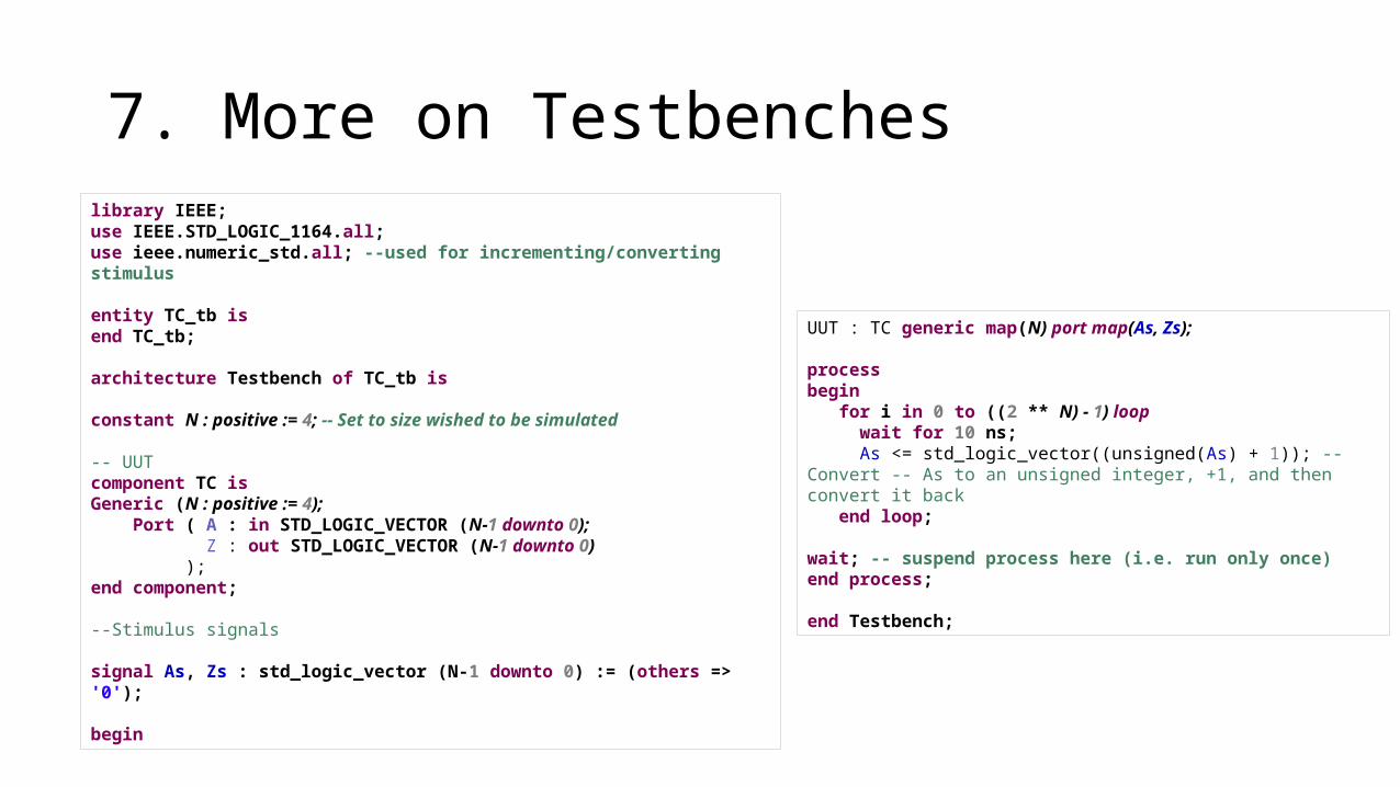
7. More on Testbencheslibrary IEEE;use IEEE.STD_LOGIC_1164.all;use ieee.numeric_std.all; --used for incrementing/converting stimulus
entity TC_tb isend TC_tb;
architecture Testbench of TC_tb is
constant N : positive := 4; -- Set to size wished to be simulated
-- UUTcomponent TC isGeneric (N : positive := 4); Port ( A : in STD_LOGIC_VECTOR (N-1 downto 0); Z : out STD_LOGIC_VECTOR (N-1 downto 0) );end component;
--Stimulus signals
signal As, Zs : std_logic_vector (N-1 downto 0) := (others => '0');
begin
UUT : TC generic map(N) port map(As, Zs);
processbegin for i in 0 to ((2 ** N) - 1) loop wait for 10 ns; As <= std_logic_vector((unsigned(As) + 1)); -- Convert -- As to an unsigned integer, +1, and then convert it back end loop;
wait; -- suspend process here (i.e. run only once)end process;
end Testbench;
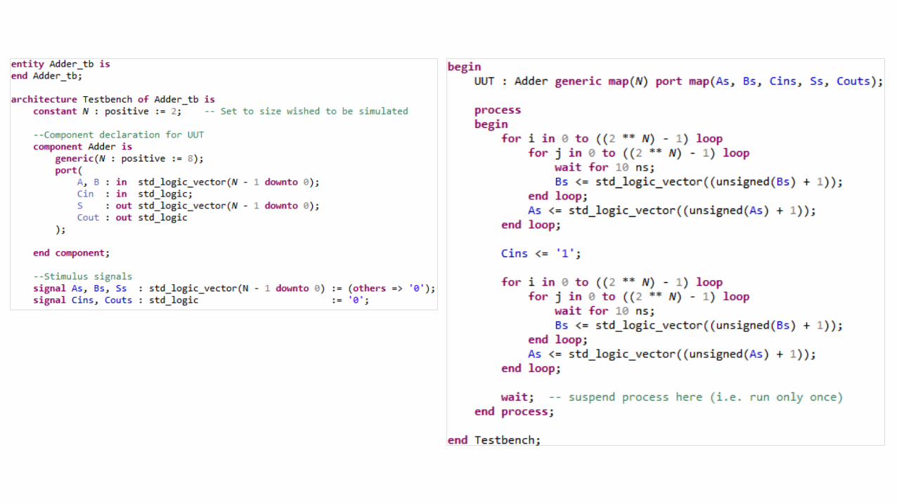
Lab 2 – ALU Design
• Let’s Practice