Embed Size (px)
Citation preview

Verilog Module Tutorial By TA Brian W. Stevens – CMPE415 – UMBC Spring 2015 – Dr. Tinoosh Mohsenin
What will this guide teach you?
This guide will go through how to use Xilinx 13.2 to create a Verilog module for a simple 8 bit
multiplier. It will show you how to add files to Xilinx projects and how to incorporate a testbench for
your Verilog module. There are also some other helpful tips as well.
1. Open up Xilinx ISE Design Suite 13.2

2. Create New Project
a. On the top toolbar go to File > New Project
b. Name your project and select the location for the project
c. Click Next
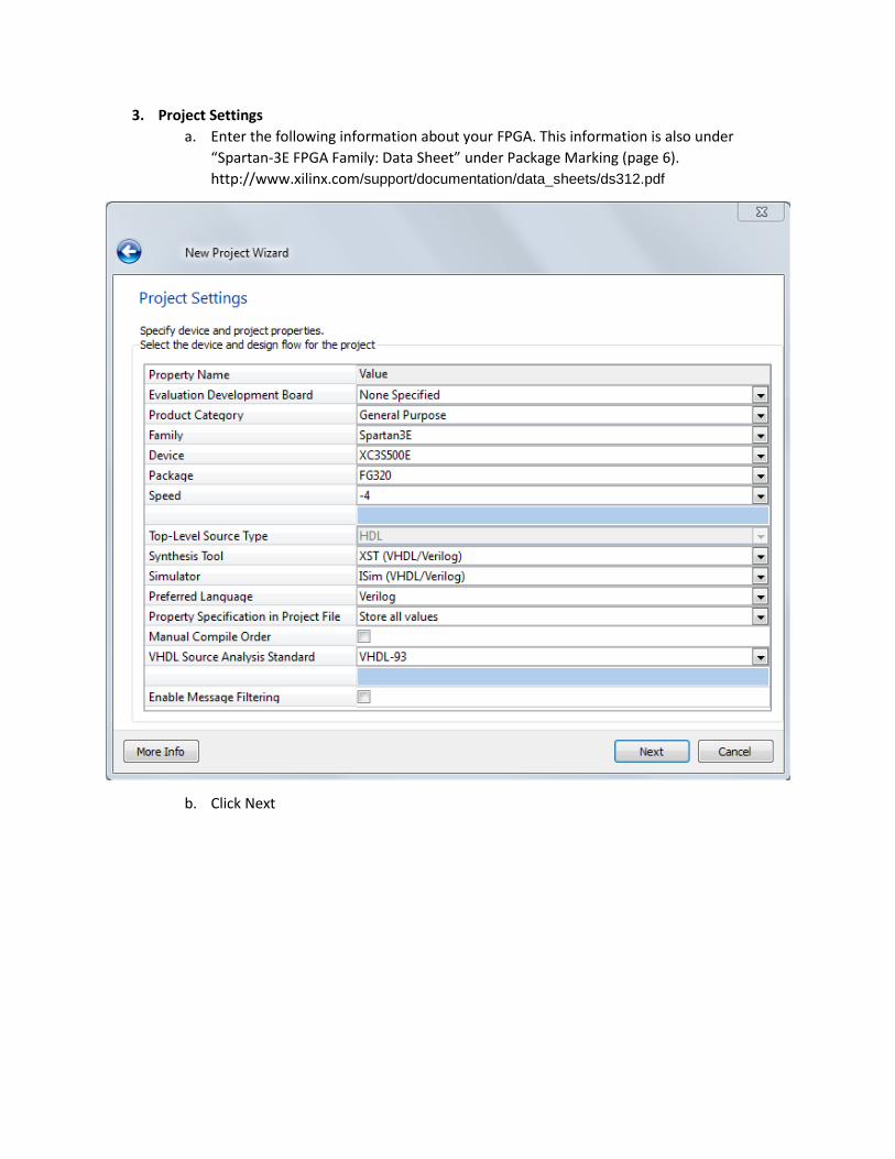
3. Project Settings
a. Enter the following information about your FPGA. This information is also under
“Spartan-3E FPGA Family: Data Sheet” under Package Marking (page 6).
http://www.xilinx.com/support/documentation/data_sheets/ds312.pdf
b. Click Next

Helpful Hint #2 – you can change the settings of your FPGA Board(Speed, Family, Package… ect)
by right clicking your project tree and selecting “Design Properties”

4. Project Summary Displayed
a. Click Finish

5. Project ISE Display
a. Your project environment will be displayed as seen below.
6. Create a New Source
a. Right click on the project and select “New Source” as seen below OR go to
Project > New Source OR you can use the buttons to the left of the hierarchy tree

Helpful Tip #1 – here you can also add existing Verilog and other source files to your design, here
are the options
a. New Source - starts wizard to create a new source _le (Verilog, VHDL, Schematic, etc...),
creating a shell if desired, and adds it for use in the project.
b. Add Source - Allows you to point to a source _le in the project directory or anywhere
else and include it for use in the project
c. Add Copy of Source - Creates a copy of the source _le in the project directory and adds
the copy for use in the project
7. New Source Type and File Name
a. After clicking “New Source”, select “Verilog Module” as the file type and enter the file
name(here as “Eight_Bit_Multipler”) as seen below.
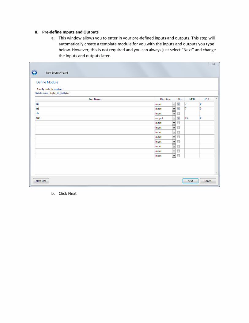
8. Pre-define Inputs and Outputs
a. This window allows you to enter in your pre-defined inputs and outputs. This step will
automatically create a template module for you with the inputs and outputs you type
below. However, this is not required and you can always just select “Next” and change
the inputs and outputs later.
b. Click Next
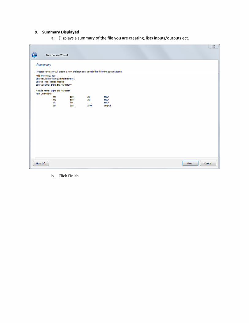
9. Summary Displayed
a. Displays a summary of the file you are creating, lists inputs/outputs ect.
b. Click Finish
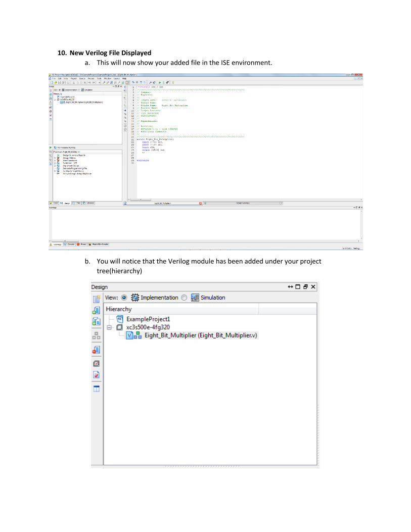
10. New Verilog File Displayed
a. This will now show your added file in the ISE environment.
b. You will notice that the Verilog module has been added under your project
tree(hierarchy)
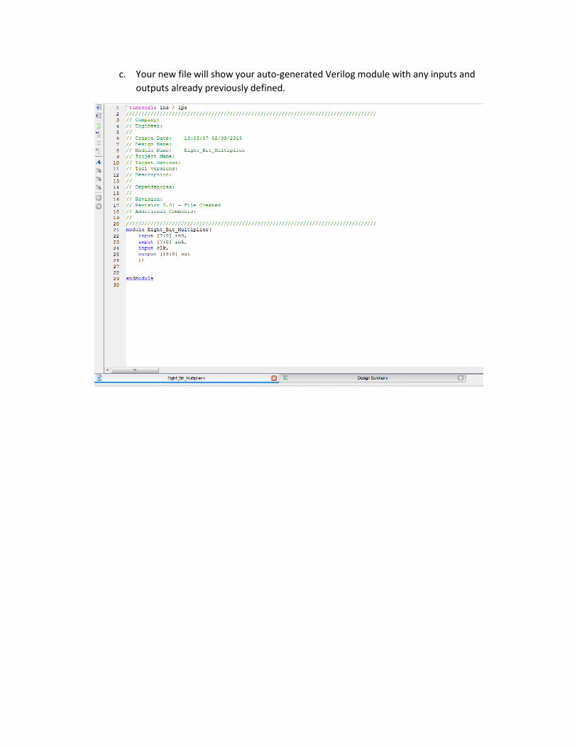
c. Your new file will show your auto-generated Verilog module with any inputs and
outputs already previously defined.

d. Completed code for the 8-bit multiplier is below. You will learn about this syntax in
class.

e. Make sure to check syntax before running simulations of your Verilog modules

11. Creating a Testbench
a. Now we will create a testbench based off our Verilog module
b. Go to Project > New Source
c. Select Verilog Test Fixture and name the file with an extension such as “_tb” or “_test”

d. Choose the associate source or the Verilog file you wish to make a testbech for.
e. Click Next
12. Summary of Testbench
a. Click Finish
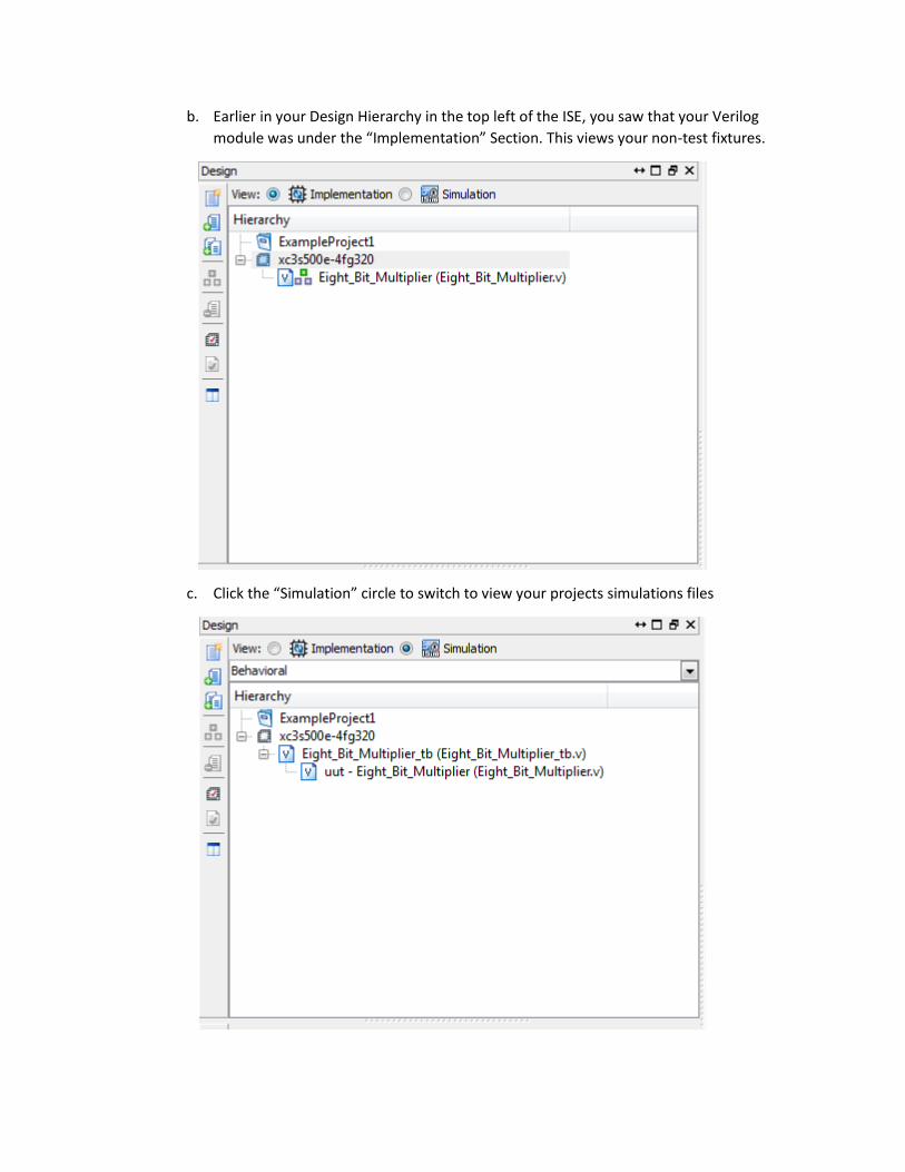
b. Earlier in your Design Hierarchy in the top left of the ISE, you saw that your Verilog
module was under the “Implementation” Section. This views your non-test fixtures.
c. Click the “Simulation” circle to switch to view your projects simulations files

d. This opens the file seen below. As you can see this testbench has auto generated inputs
and outputs based on your Verilog module. It also creates an instantiation of the Verilog
module that you are testing, in this case called “uut”, so you can test the module versus
different inputs. It also initializes the inputs to the module you are testing.
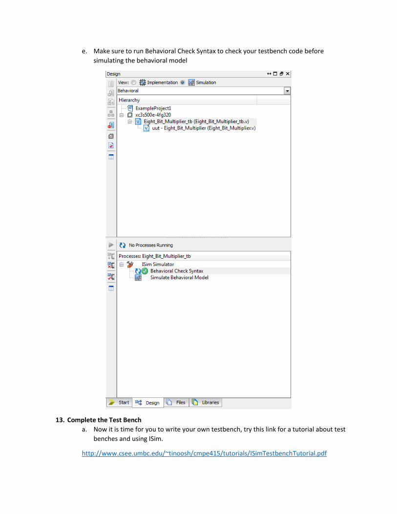
e. Make sure to run Behavioral Check Syntax to check your testbench code before
simulating the behavioral model
13. Complete the Test Bench
a. Now it is time for you to write your own testbench, try this link for a tutorial about test
benches and using ISim.
http://www.csee.umbc.edu/~tinoosh/cmpe415/tutorials/ISimTestbenchTutorial.pdf

b. A sample testbench file is listed here, provided by Dr. Tinoosh Mohsenin
http://www.csee.umbc.edu/~tinoosh/cmpe691/hw/HW1/tbench_template.v