Embed Size (px)
Citation preview
������������
������������� ����������
�
��� � � � �
�
�
� ��� � ��
�
IFCWPX0504
67829.06_01
VENTILCONVETTORIFAN COILVENTILO-CONVECTEURSGEBLÄSEKONVEKTOREN
FCW
Sostituisce il - ReplaceRemplace le n° - Ersetzt:
67829.06 / 0110
MANUALE TECNICO E D’INSTALLAZIONETECHNICAL AND INSTALLATION BOOKLETMANUEL TECHNIQUE ET D’INSTALLATIONTECH. UND INSTALLATIONSANLEITUNG

3
INDICE • CONTENTS • INDEX • INHALTSVERZEICHN
Dichiarazione di conformità • Declaration of conformity • Certificat de conformite • Konformitätserklärung 4Descizione dell’unità • Unite description • Description de l’unite • Deschreibung der EinheitComponenti principali • Main components • Composants principaux • Hauptbestandteile 5Descrizione dei componenti • Component descriptionCriteri di scelta • Selection • Critéres des Choix • Wahlkriterien 6Description des composants • Beschireibung der Komponenten 7Informazioni generali • General Information 8Information générales • Allgemine Angaben 9Limiti di funzionamento • Operating limits • Limites des fonctionnement • Grenzwerte für den Gerätebetrieb 10Dati tecnici • Technical data • Donnes technique • Technische Daten 11Potenza frigorifera resa • Delivered cooling capacity Puissance frigorifique delivree • Abgegebene Kälteleistung 12Rese termiche • Heating capacity • Puissance Thermique • Wärmeleistung 18Perdite di carico • Pressure drop • Pertes de charge • DruckverlusteLivelli di rumorosità • Sound data • Niveaux sonores • Schalleistungspegel 19Segnalazioni e tasti di controllo • Control keys and indicators 20Signalisations et touches de commande • Anzeigen und Tasten 21Imballo • PackingInstallazione dell’unità • Unit installation 22Emballage • VerpackungInstallation de l’unité • Installation des Gerätes 23Configurazione • Setting • Configuration • Konfiguration 28Accessori • Accessories • Accessories • Zubehör 31Dati dimensionali • Dimensions • Dimensions • Abmessungen 35Schemi elettrici • Wiring diagrams • Schemas eléctriques • Schaltplane 36Trasporto • Carriage • Transport • TransportSimboli di sicurezza • Safety symbol • Simboles de securite • Sicherheitssymbole 38
Servizio Assistenza Tecnica Italia 39

AERMEC S.p.A.I-37040 Bevilacqua (VR) Italia – Via Roma, 44Tel. (+39) 0442 633111Telefax (+39) 0442 93730 – (+39) 0442 93566www .aermec. com - info @aermec. com
FCW
AERMEC S.p.A. partecipa al Programma diCertificazione EUROVENT. I prodotti interessa-ti figurano nella Guida EUROVENT deiProdotti Certificati.
AERMEC S.p.A. partecipe au Programme deCerification EUROVENT. Les produits figurentdans l’Annuaire EUROVENT des ProduitsCertifiés.
AERMEC S.p.A. is partecipating in the EURO-VENT Certification Programme. Products are aslisted in the EUROVENT Dyrectory of CertifiedProducts.
AERMEC S.p.A. is am Zertifikations - programmEUROVENT beteiligt. Die entsprechendgekennzeichneten Produkte sind im EURO-VENT - Jahrbuch aufgefürt.
Bevilacqua, 1/1/2004 La Direzione Commerciale – Sales and Marketing DirectorLuigi Zucchi
4
DICHIARAZIONE DI CONFORMITÀNoi, firmatari della presente, dichiariamo sotto la nostraesclusiva responsabilità, che la macchina in oggetto èconforme a quanto prescritto dalle seguenti Direttive:- Direttiva macchine 98/37 CEE;- Direttiva bassa tensione 73/23 CEE;- Direttiva compatibilità elettromagnetica EMC 89/336 CEE.
DECLARATION OF CONFORMITYWe declare under our own responsability that the aboveequipment complies with provisions of the followingStandards:- Equipment Standard 98/37 EEC;- Low voltage Standard 73/23 EEC;- Electromagnetic compatibility Standard EMC 89/336 EEC.
CERTIFICAT DE CONFORMITENous, signataires de la présente, certifions sous notre propreresponsabilité, que l’appareil en objet est conforme aux sui-vantes Directives:- Directive appareil 98/37 EEC;- Directive basse tension 73/23 EEC;- Direttiva compatibilità elettromagnetica EMC 89/336 EEC.
KONFORMITÄTSERKLÄRUNGWir, Unterzeichner dieser Bescheinigung, bestätigen, daßdiese Geräte den Vorschriften:
- Vorschrift Geräte 98/37 EWG;- Niederspannung - Vorschrift 73/23 EWG;- Funkentstörung - Vorschrift EMC 89/336 EWG.

5
COMPONENTI PRINCIPALI MAIN COMPONENTS COMPOSANTS PRINCIPAUX HAUPTBESTANDTEILE
1 -Pannello frontale 1 -Casing 1 -Panneau avant 1 -Frontplatte2 -Ricevitore 2 -Receiver 2 -Récepteur 2 -Sensor3 -Indicatori luminosi 3 -Luminous indicators 3 -Indicateurs lumineux 3 -Kontrollleuchtten4 -Filtro aria 4 -Air filter 4 -Filtre à air 4 -Lüftfilter5 -Batteria di scambio termico 5 -Heat exchanger coil 5 -Batterie d’échange thermique 5 -Wärmetauscher6 -Deflettore mandata aria 6 -Air delivery deflector 6 -Déflecteur débit d’air 6 -Lüftleitvorrichtum7 -Interruttore acceso/spento 7 -On/Off switch 7 -Interrupteur Allumé/éteint 7 -Schalter Ein/Aus8 -Gruppo ventilante 8 -Fun unit 8 -Groupe de ventilation 8 -Lüftereinheit9 -Accessorio TLW 9 -TLW accessory 9 -Accessoire TLW 9 -Zubehör TLW
(Telecomando) (Remote-controller) (Télécommande) (I.R.Fernbedienung)10-Ionizzatore (FCW 20 - 30) 10-Ionizer (FCW 20 - 30) 10-Ioniseur (FCW 20 - 30) 10-Ionisator (FCW 20 - 30)
DESCRIZIONE DELL’UNITÀSCOPO DELLA MACCHINAIl ventilconvettore FCW è un terminale per il trattamentodell’aria di un ambiente, sia nella stagione invernale (riscal-damento) sia in quella estiva (raffreddamento).
UNITE DESCRIPTIONPURPOSE OF THE MACHINEThe FCW fan coil units treats room air during summer (coo-ling) an winter (heating) seasons.
DESCRIPTION DE L’UNITEBUT DE L’APPAREILLe ventiloconvecteur est une unité terminale servant au trai-tement de l’air d’un milieu tant en hiver qu’en été.
BESCHREIBUNG DER EINHEITEINSATZ DES GERÄTESDer Gebläsekonvektor ist eine Endeinheit für dieRaumluftbehandlung sowohl für den Winter- als auch denSommerbetrieb.
����
�� � �
��
�
�
FCW 20FCW 30
TLW

6
DESCRIZIONE DEI COMPONENTI1 PANNELLO FRONTALEL’aria viene aspirata dalle feritoie. Può essere facilmenterimosso per consentire di accedere ai filtri aria ed alle altreparti interne.2 RICEVITOREIl ricevitore di segnali infrarossi è corredato di pulsante diemergenza, che consente l’avviamento del ventilconvettoreanche in assenza del telecomando (per accedervi sollevareil pannello frontale).3 INDICATORI LUMINOSIQuesti indicatori mostrano lo stato attuale del funzionamento.4 FILTRO ARIAFiltri aria rigenerabili, sono facilmente estraibili per la pulizia.5 BATTERIA DI SCAMBIO TERMICOÈ realizzata in tubo di rame con alette in alluminio di tipoturbolenziato.6 DEFLETTORE MANDATA ARIAL’unità è dotata di un deflettore motorizzato e di alette verti-cali orientabili manualmente in modo da orientare il flussodell’aria in modo ottimale.7 INTERRUTTORE ACCESO/SPENTOInterruttore ausiliario di comando acceso/spento (per acce-dervi sollevare il pannello frontale).8 GRUPPO VENTILANTE.Il gruppo ventilante è costituito da un ventilatore di tipo tan-genziale estremamente compatto e silenzioso.9 TELECOMANDO TLW (ACCESSORIO)Il telecomando permette di impostare tutti i parametri di fun-zionamento dell’apparecchio, tali parametri vengono visualiz-zati su di un display a cristalli liquidi facilitando così le opera-zioni di programmazione. Il telecomando è alimentato con 2batterie stilo da 1,5 V di tipo R 03 AAA e funziona in manieraottimale fino ad una distanza di 7 metri dall’unità.Con ununico telecomando è possibile controllare più unità.10 IONIZZATOREGeneratore di ioni negativi (solo per FCW20 e FCW30).
FUNZIONALITÀ- Sonda di minima temperatura, per evitare getti d’aria fred-
da nel funzionamento invernale consente la ventilazionesolo se l’acqua dell’impianto è calda.
- Funzione Autorestart, dopo una interruzione dell’alimen-tazione elettrica FCW si riavvia automaticamente con lestesse impostazioni che aveva al momento dell’arresto.
- Tipo di funzionamento: automatico, raffreddamento,riscaldamento, ventilazione e depurazione aria.
- Generatore di Ioni Negativi (Display AIR): la depurazionedell’aria viene garantita tramite generatore di ioni negativi(solo per FCW 20 e FCW 30).
- Programmazione del timer per l’accensione o lo spegnimento.- Orologio.- Velocità del ventilatore interno (minima, media, massima,
AUTO).- Azionamento del deflettore aria motorizzato.- Temperatura ambiente.- Accensione e spegnimento dell’unità.
CRITERI DI SCELTA-Il ventilconvettore FCW è dotato di aspirazione dall'alto esi presta ad installazioni verticali a parete.Le Tav. 1, 2 e 3 riportano le rese frigorifere sensibili e totalialla massima velocità, in funzione della temperatura del-l'acqua entrante, del suo salto termico, della temperatura abulbo secco e a bulbo umido dell'aria; Le prestazioni allevelocità media e minima si ottengono applicando i relativicoefficienti correttivi. I diagrammi della Tav.4 riportano lapotenza termica resa alla massima velocità, in funzionedella portata d'acqua e della differenza di temperatura traacqua entrante e ed aria entrante; per le velocità inferiorifare riferimento ai relativi coefficienti correttivi.Il diagramma della Tav. 5 riporta le perdite di carico latoacqua.Nella tabella Tav. 6 è riportato il livello di potenza e dipressione sonora del ventilconvettore alle varie velocità.
COMPONENT DESCRIPTION1 OPERATOR PANEL Air intake is via the grille slats. This grille can easily be remo-ved for access to air filters and other internal components.2 RECEIVERThe infrared signal receiver is equipped with an emergencypushbutton that enables start-up of the fancoil also withoutthe remote control (for access, raise the front panel).3 LUMINOUS INDICATORS This indicators display current operation status.4 AIR FILTER Washable air filters, easily removable for cleaning.5 HEAT EXCHANGER COIL Comprising copper pipe with aluminium circulating flow fins.6 AIR DELIVERY DEFLECTOR The unit is fitted with a motor-driven deflector and verticalfins that can be manually adjusted for optimal air flow.7 ON/OFF SWITCH Auxiliary on/off switch (for access raise the front panel).8 FAN UNIT.The fan unit comprises an extremely compact and silenttangential type fan.9 TLW REMOTE CONTROL (ACCESSORY)The remote control enables the user to set all unit operatingparameters; these parameters are shown on an LCD displayto facilitate programming. The remote control runs on two1.5 V batteries, monopole type R 03 AAA and optimal ope-ration is guaranteed up to 7 meters from the unit. With oneremote control is possible to set more units10 IONIZERNegative Ion Generator (only for FCW20 and FCW30).
FUNCTIONALITY- Minimum temperature sensor, to avoid streams of cold air
in the winter operation mode, allows ventilation only ifthe water of the plant is hot.
- Auto Restart Function, after an electrical power interrup-tion, the FCW will automatically restart with the same set-tings that it had at the time it stopped.
- Operation modes: automatic, cooling, heating, ventila-tion, air cleaner.
- Negative Ion Generator (Display AIR): air purification isensured by a negative ion generator (only for FCW 20 andFCW 30).
- Timer programming for activation and shutdown;- Clock.- Internal fan speed (minimum, medium, maximum,
AUTO).- Activation of motor-driven air deflector.- Ambient temperature;- Unit on/off controls.
SELECTION CRITERIAThe FCW fancoil with upper air-intake is ideal for verticalwall installation.Tav 1, 2 and 3 show the sensitive and total cooling capacityof the unit at maximum speed according to the temperatureof inlet water, the thermal head, the dry bulb and wet bulbtemperature of the air; Performances at medium and lowspeeds are obtained by applying the relative correctioncoefficients. The diagrams shown in Tav. 4 specify the hea-ting capacity at maximum speed according to water flowand the temperature difference detected between inlet waterand intake air (for lower speeds, refer to the relative correc-tion coefficients).The diagram in Tav. 5 indicates the load loss on water side.In the table shown at Tav. 6 is indicated the power leveland sound pressure of the fancoil at different speeds.

7
DESCRIPTION DES COMPOSANTS1 PANNEAU AVANTL'air est aspiré par les fentes. Le panneau avant est facile àenlever pour permettre d'accéder aux filtres à air et auxautres composants internes.2 RÉCEPTEURLe récepteur de signaux infrarouges dispose d'un boutond'urgence qui permet de mettre en marche le ventilocon-vecteur même en l'absence de la télécommande (pour yaccéder, soulever le panneau avant).3 INDICATEURS LUMINEUX Ces indicateurs permettent de connaître l'état de fonction-nement présent4 FILTRE À AIRFiltres à air réutilisables, faciles à extraire pour le nettoyage.5 BATTERIE D'ÉCHANGE THERMIQUEElle est réalisée en tube de cuivre avec ailettes en alumi-nium du type turbulence.6 DÉFLECTEUR REFOULEMENT AIRL'unité est équipée d'un déflecteur motorisé et d'ailettesverticales orientables manuellement, de façon à donner uneorientation optimale au jet d'air.7 INTERRUPTEUR ALLUMÉ/ÉTEINTInterrupteur auxiliaire de commande allumé/éteint (pour yaccéder, soulever le panneau avant).8 GROUPE DE VENTILATION.Le groupe de ventilation est formé d'un ventilateur du typetangentiel, extrêmement compact et silencieux.9 TÉLÉCOMMANDE TLW (ACCESSOIRE)La télécommande permet de programmer tous les paramè-tres de fonctionnement de l'appareil; ces paramètres sontvisualisés sur un afficheur à cristaux liquides, ce qui faciliteles opérations de programmation. La télécommande est ali-mentée par 2 piles bâton de 1,5 V du type R 03 AAA, etassure un fonctionnement optimal jusqu'à une distance de 7mètres de l'unité. Avec une unique télécommande, il estpossible de contrôler plusieurs unités.10 IONISEUR (pour FCW20 et FCW30 seul)Générateur d’ions négatifs.
FONCTIONNEMENT- Sonde de température minimale qui évite les jets d'air
froid en fonctionnement d'hiver et permet la ventilationseulement si l'eau de l'installation est chaude.
- Fonction Autorestart, après une coupure de courant, FCWse remet automatiquement en marche et utilise les pro-grammations qu'il avait au moment où il s'est arrêté.
- type de fonctionnement: automatique, refroidissement,chauffage et ventilation.
- Generatore à ions négatifs (Display AIR): la depurazionedell’aria viene garantita tramite Générateur d’ions négatifs(pour FCW20 et FCW30 seul).
- Programmation du temporisateur pour l'allumage ou l'arrêt.- Horloge.- Vitesse du ventilateur interne (minimale, moyenne, maxi-
male, AUTO).- Commande du déflecteur air motorisé.- Température ambiante.- Mise en marche et arrêt de l'unité.
CRITÈRES DE CHOIXLe ventilateur convecteur FCW est équipé d'aspiration parle haut et convient aux installations verticales murales. LeTav. 1, 2, et 3 indique les rendements frigorifiques sensibleset totaux à la vitesse maximale, en fonction de la températu-re de l'eau entrante de son écart thermique, de la tempéra-ture à bulbe sec et à bulbe humide de l'air.Les performances aux vitesses moyennes et minimum sontobtenues en appliquant les coefficients de correction corre-spondants.Les diagrammes totaux du tav.4 indiquent la puissance ther-mique de rendement à la vitesse maximum, en fonction dudébit d'eau et de la différence de température entre eau etair entrants ; pour les vitesses inférieures, consulter les coef-ficients de correction correspondants.Le diagramme du tav. 5 indique les pertes de charge côtéeau.Le table du Tav. 6 indique le niveau de puissance et de pres-sion sonore du ventilateur convecteur aux différentes vitesses.
COMPONENT DESCRIPTION1 FRONTPLATTEDie Luft wird durch das Lüftungsgitter angesaugt, das aufeinfache Weise abgenommen werden kann, um dieLuftfilter und die innenliegenden Einrichtungen zu errei-chen.2 SENSORDer Infrarotsensor ist mit einer Nottaste versehen, mit derder Gebläsekonvektor auch ohne Fernbedienung einge-schaltet werden kann (die Taste ist nach Abheben derFrontplatte zugänglich).3 KONTROLLLEUCHTENDie Kontrollleuchten zeigen den aktuellen Betriebszustand an.4 LUFTFILTERDie Luftfilter können regeneriert und für die Reinigung aufeinfache Weise ausgebaut werden.5 WÄRMETAUSCHERKupferrohre mit Aluminiumflügeln zur Erzeugung turbulen-ter Strömung.6 LUFTLEITVORRICHTUNDas Gerät ist mit einer motorgetriebenen Luftleitvorrichtungversehen und besitzt senkrechte Lüftungsschlitze, die vonHand verstellt werden können, um die Luftströmung opti-mal zu verteilen.7 SCHALTER EIN/AUSHilfsschalter ein/aus (der Schalter ist nach Abnahme derFrontplatte zugänglich).8 GEBLÄSEDas Gebläse arbeitet mit einem sehr geräuscharmen undkompakten Tangentiallüfter.9 FERNBEDIENUNG TLW (ZUBEHÖR)Die Fernbedienung ermöglicht die Einstellung allerBetriebsparameter des Gerätes. Diese werden auf einerLCD- Anzeige dargestellt, um die Programmierung zu erlei-chtern. Die Fernbedienung wird mit 2 1,5 V - Mignonzellen(Typ R 03 AAA) betrieben und läßt sich in bis zu 7 MeternEntfernung vom Gerät verwenden. Mit einer einzelnenFerbedienung ist es möglich meher als eine Einheit zusteuern.10 IONISATOR (nur für FCW20 und FCW30)Erzeuger der Negativen Ionen.
FUNKTIONEN- Zur Vermeidung kalter Luftstrahlen im Winterbetrieb
gestattet der Mindesttemperaturfühler die Belüftung nurdann, wenn das Wasser der Anlage warm ist.
- Funktion Automatischer Neustart; nach einemStromausfall startet FCW automatisch wieder mit den glei-chen Einstellungen, die vor dem Stillstand gesetzt waren.
- Betriebsweise: Automatik, Kühlung, Heizung und Lüftung.- Generatore mit negativ geladenen Ionen (Display AIR): la
Luftreinigung dell’aria viene garantita tramite Erzeuger derNegativen Ionen (nur für FCW20 und FCW30).
- Programmierung der Zeitschaltuhr zum Ein- undAusschalten;
- Uhr;- Lüftergeschwindigkeit (minimal, mittel, maximal, AUTO);- Betätigung der motorgetriebenen Luftleitbleche;- Raumtemperatur;- Ein- und Ausschalten des Geräts.
AUSWAHLKRITERIENDer Gebläsekonvektor FCW ist mit Ansaugung von obenausgestattet und eignet sich für die senkrechteWandmontage.In Tav 1, 2 und 3 sind die fühlbaren und Gesamt-Kälteleistungenbei max. Drehzahl je nach Eintrittswassertemperatur,Temperaturdifferenz, Lufttemperatur gemäß Trocken- oderFeuchtkugel bezüglich der fühlbaren und Gesamtleistung auf-geführt. Die Leistungen bei mittlerer oder Mindestdrehzahl erhältman durch Anwendung der entsprechendenKorrekturkoeffizienten. In den Diagrammen der Tav. 4 ist dieHeizleistung bei max. Drehzahl je nach geförderter Wassermengeund Temperaturunterschied zwischen Eintrittswasser undEintrittsluft aufgeführt. Hinsichtlich der niedrigeren Drehzahlwerteist auf die Korrekturkoeffizienten Bezug zu nehmen.Das Diagramm der Tav. 5 enthält die wasserseitigenDruckverluste. In Tabelle Tav. 6 sind die Schallleistungs-und Schalldruckpegel des Gebläsekonvektors bei unter-schiedlichen Drehzahlen aufgeführt.

8
INFORMAZIONI GENERALIIl telecomando a raggi infrarossi (accessorio) consente dieffettuare l’accensione, lo spegnimento e tutte le operazionidi controllo e di programmazione del condizionatore.Un sistema di controllo verifica tutti i parametri funzionali e,automaticamente, esegue tutte le operazioni necessarie perconsentire il mantenimento delle condizioni ambiente desi-derate, che dovranno essere impostate prima dell’accensione.Il sistema di controllo rende inoltre disponibili alcune fun-zioni automatiche per facilitare le operazioni più ricorrenti.
FUNZIONAMENTO AUTOMATICOQuando viene impostato il funzionamento automatico(Display: AUTO), il sistema di controllo, in base alle condi-zioni dell’ambiente, decide le modalità di funzionamento.
RISCALDAMENTONel funzionamento in riscaldamento (Display: HEAT) il ven-tilconvettore funzionerà fino al raggiungimento della tempe-ratura impostata dal telecomando, raggiunta la quale si fer-merà, per ripartire non appena il sensore interno rilevi unabbassamento della temperatura ambiente.
RAFFREDDAMENTONel funzionamento in raffreddamento (Display: COOL) ilventilconvettore funzionerà fino al raggiungimento dellatemperatura impostata dal telecomando, raggiunta la qualesi fermerà, per ripartire non appena il sensore interno rileviun innalzamento della temperatura ambiente.
VENTILAZIONENel funzionamento in ventilazione (Display: FAN) il ventilatorepuò funzionare senza che l’impianto termico sia in funzione.
VELOCITÀ DEL VENTILATOREImpostando la velocità della ventola (Display: SPEED) inAUTO il ventilconvettore FCW selezionerà la velocità piùadatta in funzione delle condizioni ambientali, per raggiun-gere la temperatura impostata; è inoltre possibile sceglieremanualmente la velocità preferita agendo sul tasto SPEED.
TIMERE’ possibile impostare l’orario di accensione e l’orario dispegnimento oppure semplicemente il tempo di accensionedal momento dell’avviamento.
FUNZIONAMENTO NOTTURNOImpostando il funzionamento notturno (Display: SLEEP) ilventilconvettore attiva un programma che consente un gra-duale abbassamento (in riscaldamento) o innalzamento (inraffreddamento) della temperatura sino a raggiungere lospegnimento all’orario impostato, migliorando le condizionidi benessere nelle ore notturne.Può essere attivato in qualsiasi momento della giornata,solo se il ventilconvettore è già in funzione nelle modalitàriscaldamento, raffreddamento.
DEPURAZIONE DELL’ARIA (solo per FCW20 e FCW30)Impostando il funzionamento con depurazione dell’aria(Display: AIR) il ventilconvettore attiverà il generatore degliioni negativi posto al suo interno.
ORIENTAMENTO DEI FLUSSI D’ARIAI deflettori motorizzati devono essere regolati solamentecon il telecomando, agendo sul tasto AUTO (movimentooscillante) o sul tasto DIREC. ( 5 posizioni fisse)Il flusso d’aria in senso laterale deve essere regolatomanualmente, agendo sui deflettori verticali.
PULIZIA DEL FILTRO DELL’ARIAAssicurarsi che i filtri dell’aria siano sempre puliti. Un accu-mulo di polvere sui filtri provoca una riduzione del flussod’aria e quindi delle prestazioni, ed un aumento del rumore.
INTERRUZIONE DI CORRENTESe viene a mancare la tensione il ventilconvettore si ferma.Al ritorno della stessa, il ventilconvettore ripartirà con lestesse impostazioni che aveva al momento dell’arresto.
GENERAL INFORMATIONSThe infrared remote control (accessory) enables unit start-up, shutdown and all control and programming operationsfor the conditioner.A control system monitors all operating parameters andperforms all operations automatically to ensure maintenanceof the required ambient conditions set prior to start-up.The control system is also designed with a number of auto-matic functions to facilitate the most frequently used opera-tions.
AUTOMATIC OPERATIONWhen automatic mode is set (Display: AUTO), the controlsystem sets the operation mode automatically according tothe ambient conditions.
HEATING In heating mode (Display: HEAT) the fancoil operates untilthe temperature set on the remote control is reached afterwhich it stops and re-starts whenever the temperature fallsbelow the setting.
COOLING In cooling mode (Display: COOL) the fancoil operates untilthe temperature set on the remote control is reached afterwhich it stops and re-starts whenever the temperature raisesabove the setting.
FANIn ventilation mode (Display: FAN) the fan can operateindependently of the heating system.
FAN SPEED When the fan speed (Display: SPEED) is set to AUTO theFCW fancoil selects the speed most suited to ambient condi-tions to reach the required temperature; the required speedcan also be selected manually by means of the key.
TIMERThe activation and shutdown times can be set by the useron the timer or simply the activation time after start-up.
SLEEP MODE When night-time mode is set (Display: SLEEP) the fancoilactivates a program that prevents excessive cooling or hea-ting during the night or rest times. This can be activated atany time of day, provided that the fancoil is set to heatingcooling.
CLEAN (only for FCW20 and FCW30)When the unit is set for air purification (Display: AIR) thefancoil activates the negative ion generator installed insidethe unit.
ORIENTAMENTO DEI FLUSSI D’ARIAThe motor-driven deflectors must be adjusted by means ofthe remote control only, using keys AUTO (oscillating) orDIREC ( 5 fixed positions)The lateral air flow must be adjusted manually by means ofthe vertical deflectors.
CLEANING THE AIR FILTER Check air filters regularly; built-up dust will hamper air flowand efficient performance, as well as increase operatingnoise.POWER SUPPLY INTERRUPTIONThe fancoil is shutdown in the event of a power supply failu-re.On restoral of power the fancoil restarts according to theprevious settings at the time of shutdown.

9
INFORMATIONS GÉNÉRALESLa télécommande à rayons infrarouges (accessorie) permetd'allumer l'appareil, de l'éteindre et d'effectuer toutes les opé-rations de commande et de programmation du climatiseur.Un système de commande contrôle tous les paramètres de fonc-tionnement et effectue automatiquement toutes les opérationsnécessaires afin de permettre le maintien des conditions ambian-tes désirées, qui devront être programmées avant l'allumage.Le système de commande met en outre à disposition plu-sieurs fonctions automatiques qui permettent de faciliter lesopérations les plus fréquentes.
FONCTIONNEMENT AUTOMATIQUEEn mode de fonctionnement automatique (Afficheur : AUTO),c'est le système de commande qui, en fonction des condi-tions ambiantes, décide des modalités de fonctionnement.
CHAUFFAGEEn mode de fonctionnement chauffage (Afficheur : HEAT),le ventiloconvecteur fonctionnera jusqu'à atteindre latempérature programmée avec la télécommande, après quoiil s'arrêtera, et redémarrera dès que le capteur interne enre-gistrera une baisse de température.
REFROIDISSEMENTEn mode de fonctionnement refroidissement (Afficheur :COOL), le ventiloconvecteur fonctionnera jusqu'à atteindrela température programmée avec la télécommande, aprèsquoi il s'arrêtera, et redémarrera dès que le capteur interneenregistrera une augmentation de température.
VENTILATIONEn mode de fonctionnement ventilation (Afficheur : FAN), leventilateur peut fonctionner sans que l'installation thermi-que soit en service.
VITESSE DU VENTILATEURLorsque l'on programmera la vitesse du ventilateur(Afficheur : SPEED) sur AUTO, le ventiloconvecteur FCWsélectionnera la vitesse la plus appropriée, en fonction desconditions ambiantes, pour atteindre la température pro-grammée; il est en outre possible de choisir manuellementla vitesse désirée en agissant sur la touche SPEED.
TIMERIl est possible de programmer l'heure d'allumage et l'heured'arrêt ou simplement la durée du fonctionnement à partirde la mise en marche.
FONCTIONNEMENT NOCTURNELorsque l'on programme le fonctionnement nocturne(Afficheur : SLEEP), le ventiloconvecteur active un program-me qui empêche un refroidissement ou un chauffage exces-sifs pendant les heures de repos. Ce fonctionnement peutêtre activé à tout moment de la journée, à condition que leventiloconvecteur soit déjà en service en modalité de chauf-fage, de refroidissement.
ÉPURATION DE L'AIR (POUR FCW20 ET FCW30 SEUL)Lorsque l'on programme le fonctionnement permettant l'épu-ration de l'air (Afficheur : AIR), le ventiloconvecteur active legénérateur d'ions négatifs qui se trouve dans l'appareil.
ORIENTATION DES JETS D'AIRLes déflecteurs motorisés doivent être réglés uniquement avecla télécommande, en agissant sur la touche AUTO (mouve-ment oscillant) ou sur la touche DIREC. (5 positions fixes).Le débit d'air dans le sens latéral doit être réglé manuellement,en agissant sur les déflecteurs verticaux.
NETTOYAGE DU FILTRE A AIRS'assurer que les filtres de l'air sont toujours propres. Touteaccumulation de poussière sur les filtres réduit sensiblement leflux de l'air et les performances tout en augmentant le bruit.
COUPURE DE COURANT En cas de coupure de courant, le ventiloconvecteur s'arrête.Lorsque le courant revient, le ventiloconvecteur se remet enmarche et utilise les programmations qu'il avait au momentauquel il s'est arrêté.
ALLGEMEINE ANGABENDie Infrarot - Fernbedienung (zubehör) ermöglicht das Ein-und Ausschalten sowie alle zur Steuerung undProgrammierung des Klimagerätes notwendigen Operationen.Ein automatisches Steuerungssystem überprüft alleParameter und nimmt alle erforderlichen Operationen zurAufrechterhaltung des gewünschten und zuvor eingestelltenRaumklimas vor.Die Steuerung bietet außerdem einige automatische Funktionen,um häufig vorkommende Operationen zu automatisieren.
BETRIEBSART AUTOMATIKWenn die Betriebsart Automatik gewählt wird (Anzeige:AUTO), wird die Betriebsweise vom System je nachUmgebungsbedingungen automatisch gewählt.
HEIZUNGBei der Betriebsart Heizung (Anzeige: HEAT) bleibt derGebläsekonvektor bis zum Erreichen der mittels der Fernbedienungeingestellten Temperatur in Betrieb. Er hält dann an, bis derinterne Sensor erneut eine Absenkung der Temperatur meldet.
KÜHLUNGBei der Betriebsart Kühlung (Anzeige: COOL) bleibt derGebläsekonvektor bis zum Erreichen der mittels derFernbedienung eingestellten Temperatur in Betrieb. Er hält dann an,bis der interne Sensor erneut eine Erhöhung der Temperatur meldet.
LÜFTUNGBei der Betriebsart Lüftung (Anzeige: FAN) kann der Lüfter beiabgeschaltetem Wasserkreislauf in Betrieb genommen werden.
LÜFTERGESCHWINDIGKEITWenn die Lüftergeschwindigkeit (Anzeige: SPEED) auf AUTOgestellt wird, wählt der Gebläsekonvektor FCW die je nachUmgebungsbedingungen am besten zum Erreichen der gewün-schten Temperatur geeignete Lüftergeschwindigkeit. Darüberhinaus kann eine Einstellung der gewünschten Geschwindigkeitmit der Taste SPEED vorgenommen werden.
ZEITSCHALTUHREs kann sowohl eine Einstellung der Ein- und Ausschaltzeitals auch nur die Einstellung der Betriebszeit nach demEinschalten vorgenommen werden.
NACHTBETRIEBWenn die Betriebsart Nacht gewählt wird (Anzeige: SLEEP),aktiviert der Gebläsekonvektor ein Programm, das eineübermässige Kühlung bzw. Heizung während der Nachtvermeidet. Diese Betriebsweise kann zu jedem Zeitpunktgewählt werden, jedoch nur dann, wenn sich derGebläsekonvektor bereits in einer der BetriebsartenHeizung, Kühlung befindet.
LUFTREINIGUNG (NUR FÜR FCW20 UND FCW30)Wenn die Betriebsart Luftreinigung gewählt wird (Anzeige:AIR negativen Ionengenerator.
ORIENTIERUNG DER LUFTSTRÖMUNGDie motorisierten Lüftungsschlitze dürfen nur mit derFernbedienung, durch Druck auf die Taste AUTO (oszillie-rende Bewegung) oder die Taste DIRECT ( 5 festePositionen), eingestellt werden.In seitlicher Richtung wird der Luftstrom von Hand einge-stellt, indem bei abgeschaltetem Gebläsekonvektor FCW diesenkrechten Lüftungsschlitze entsprechend verstellt werden.
REINIGUNG DES LUFTFILTERSSicherstellen, dass die Luftfilter stets sauber sind. EineStaubansammlung an den Filtern verursacht eineReduzierung des Luftstroms und folglich der Leistung sowiedie Zunahme des Geräuschpegels.
UNTERBRECHUNG DER SPANNUNGSVERSORGUNGBei Unterbrechung der Stromzufuhr bleibt derGebläsekonvektor stehen.Wenn die Stromversorgung wieder hergestellt ist, läuft derGebläsekonvektor unter Beibehaltung der zuvor vorgenom-menen Einstellungen an.

10
MINIMA TEMPERATURA MEDIA ACQUA Temperatura a bulbo secco dell’aria ambiente °CMINIMUM AVERAGE WATER TEMPERATURE Dry bulb temperature °CTEMPÉRATURE MINIMUM MOYENNE DE L’EAU Température bulbe sèche °CMINIMALE MITTLERE WASSERTEMPERATUR Temperatur T.K. °C
21 23 25 27 29 31Temperatura a bulbo umido 15 3 3 3 3 3 3dell’aria ambiente °C 17 3 3 3 3 3 3Wet bulb temperature °C 19 3 3 3 3 3 3Température bulbe humide °C 21 6 5 4 3 3 3Temperatur F.K. °C 23 - 8 7 6 5 5
INFORMATIONS COMPLEMENTAIRESLIMITES DE FONCTIONNEMENTTempérature maximale d'entrée de l'eau 80 [°C]Pression maximale de fonctionnement 8 [bar]Le fonctionnement continu de l'appareil en refroidissementdans une pièce aved un taux de humidité rélative très élévé,peut provoquer la formation de quelques gouttes de con-densats à proximitè du soufflage de l'air qui pourraient cou-ler de l'appareil. Les condensats pourraient tomber sur lesobjets au dessous ou au sol. Pour éviter des phénomènes decondensation sur la structure extérieure de l'appareil, latempérature moyenne de l'eau ne doit pas être inférieureaux limites indiquées dans le tableau ci-dessous, qui dépen-dent des conditions thermo-hygrométriques de l'airambiant. Les limites précitées se rapportent au fonctionne-ment à la vitesse minimale.En cas de longue période avec ventilateur éteint et passaged'eau froide dans la batterie la formation de condensas àl'extérieur de l'appareil est possible , il est conseillé d'insé-rer l'accessoire vanne 3 voies.
WEITERE INFORMATIONEN BESCHRÄNKUNGEN DES BETRIEBSMaximale Wassereintrittstemperatur 80 [°C]Maximaler Betriebsdruck 8 [bar]Wenn das Klimagerät im Dauerbetrieb (in der BetriebsartKühlung) in einer Atmosphäre Feuchtigkeit arbeitet, bildensich Kondensationströpfchen am Luftaustritt derInneneinheit und können auf den Boden abtropfen. DasKondenswasser könnte auf den Boden oder auf die evtl.unter dem Klimagerät befindlichen Gegenstände tropfen. Um Kondensationserscheinungen auf der Außenseite derEinheit zu verhindern, darf die durchschnittlicheWassertemperatur nicht unter die Grenzwerte in unten-stehender Tabelle sinken.Die Grenzwerte hängen von den thermohygrometrischenBedienungen der Raumluft ab und betreffen die kritischsteAnwendung den Betrieb bei Mindestdrehzahl.Beim stehenden Ventilator und Kaltwasserdurchfluß in denWärmetauscher ist eine Kondesatbildung am Gerät möglich,als Zubehör das Dreiwege-Ventil einzubauen.
INFORMAZIONI AGGIUNTIVELIMITI DI FUNZIONAMENTOMassima temperatura di ingresso acqua 80 [°C]Massima pressione di esercizio 8 [bar]Se il ventilconvettore funziona in modo continuativo in raf-freddamento all’interno di un ambiente con elevata umiditàrelativa, si potrebbe avere formazione di condensa sullamandata dell’aria. Tale condensa, potrebbe depositarsi sulpavimento e sugli eventuali oggetti sottostanti. Per evitarefenomeni di condensazione sulla struttura esterna dell’appa-recchio con ventilatore in funzione, la temperatura mediadell’acqua non deve essere inferiore ai limiti riportati nellatabella sottostante, che dipendono dalle condizioni termo-igrometriche dell’aria ambiente. I suddetti limiti si riferisco-no al funzionamento con ventilatore in moto alla minimavelocità. In caso di prolungata situazione con ventilatore spento epassaggio di acqua fredda in batteria, è possibile la forma-zione di condensa all’esterno dell’apparecchio, pertanto siconsiglia l’inserimento dell’accessorio valvola a tre vie.
ADDITIONAL INFORMATION OPERATION LIMITSMaximum water inlet temperature 80 [°C]Maximum working pressure 8 [bar]If the air conditioner works continuously on cooling mode insi-de a room with high relative humidity, there might be the pro-duction of condensate by air delivery of the indoor unit. Thecondensate might collect on the object underneath or on thefloor. To prevent the formation of condensation on the exterior ofthe unit while the fan is operating, the average water tempe-rature should not drop beneath the limits shown in the tablebelow, determined by the ambient conditions. These limits refer to unit operation with fan at minimumspeed. Note that condensation may form on the exterior of the unitif cold water circulates through the coil while the fan is offfor prolonged periods of time, so it is advisable to fit theadditional three-way valve.
Limiti di portata • Water flow limits • Limites de débit • Durchflußgrenzen:MOD. FCW 20 FCW 30 FCW 40Portata minima • Minimum water flow
l/h 150 200 250Débit minimum • MindestflußPortata massima • Maximum water flow
l/h 1150 1550 1550Débit maximum • Höchstfluß

11
Le prestazioni sono riferite alle seguenti condizioni:❊ riscaldamento:
T. ingresso acqua = 70 °C; ingresso aria = 20 °C b. s.∆ t acqua = 10 °C (alla velocità massima).
❆ raffreddamento:T. ingresso acqua = 7 °C; T. ingresso aria = 27 °C b. s./19 °C b. u.∆ t acqua = 5 °C (alla velocità massima).
Performances refer to following conditions:❊ heating:
T. water in = 70 °C; air in = 20 °C d. b.∆ t water = 10 °C (at high speed).
❆ cooling:T. water in = 7 °C; air in = 27 °C d. b. / 19 °C w. b.∆ t water = 5 °C (at maximum speed).
Mod. FCW 20 FCW 30 FCW40
❊ Potenza termica • Heating capacitymax. [W] 4800 6600 10200
Puissance thermique • Wärmeleistungmed. [W] 4150 5900 8600min. [W] 3400 5050 7000
Potenza termica (acqua ingresso 50°C) Heating capacity (water inlet 50°C) [W] 3000 3800 6100Puissance thermique (entrée eau 50°C) Wärmeleistung (Wassereintritt 50°C)
❊ Portata acqua • Water flow • Débit d’eau • Massenstrom [l/h] 413 570 877❊ Perdite di carico acqua • Water pressure drops
Pertes de charge d’eau • Wasserdruckverlust[kPa] 18 25 22
❆ Potenza frigorifera • Cooling capacitymax. [W] 2100 2900 4600
Puissance frigorifique • Kälteleistungmed. [W] 1900 2700 4150min. [W] 1600 2500 3700
❆ Potenza frigorifera sensibile • Sensible cooling capacitymax. [W] 1750 2300 3600
Puissance frigorifique sens. • Sensible külleistungmed. [W] 1470 2090 3100min. [W] 1200 1700 2650
❆ Portata acqua • Water flow • Débit d’eau • Massenstrom [l/h] 361 500 791❆ Perdite di carico acqua • Water pressure drops
[kPa] 18 21 24Pertes de pression d’eau • Wasserdrunckverlust
Portata d’aria • Air flowmax. [m3/h] 440 540 890
Débit d’air • Volumenstrommed. [m3/h] 350 440 690min. [m3/h] 270 370 530
Velocità del ventilatore • Fan speedmax. [rpm] 1170 1190 1235
Vitesse ventilateur • Ventilatordrehzahlmed. [rpm] 970 1045 1000min. [rpm] 750 875 795
Numero di ventilatori • Fan number Nombre de ventilateurs • Anzahl derVentilatoren
n° 1 1 1
Contenuto acqua • Water content Contenance en eau • Wassenhalt
[l] 0,45 0,68 1,70
Potenza max. motore • Max. motor power Puissance max. moteur • Max. Motorleistung
[W] 27 29 50
Corrente max. assorbita • Max. input current Tension max. d’entrée • Max. Stromaufnahme
[A] 0,12 0,13 0,22
Attacchi batteria • Coil connections • Raccords batterie • Anschlüsse des Wärmeaustauschers
ø Gas 1/2”F 1/2”F 1/2”F
Dimensioni • DimensionsAltezza • Height • Hauter • Höhe [mm] 270 270 320
Dimensions • AbmessungenLarghezza • Width • Largeur • Breite [mm] 795 795 1200Profondità • Depth • Profondeur • Tiefe [mm] 178 178 210
Peso netto • Net weight • Poid net • Nettogewicht [kg] 9 10 20Tensione di alimentazione • Power supply • Alimentation electrique • Spanung-Frequenz = 230 V-1 N-50 Hz ±10 %
DATI TECNICI • TECHNICAL DATA • DONNEES TECHNIQUES • TECHNISCHE DATEN
EUROVENT CERTIFIED PERFORMANCE
Les performances sont données aux conditions suivantes:❊ chauffage:
temp. d’entrée de l’eau = 70 °C; temp. d’entrée de l’air = 20 °C b. s.∆ t eau = 10 °C (vitesse maximum ventilateur).
❆ refroidissement:temp. d’entrée de l’eau = 7 °C;temp. d’entrée de l’air = 27 °C b. s. / 19 °C b. u.∆ t eau = 5 °C (vitesse maximum ventilateur).
Die technischen Daten beziehen sich auf die folgendenBedingungen:❊ Heizung: Wassereintritt:
Heizung: Wassereintritt= 70 °C; Lufteintritt = 20 °C t. Thk∆ t wasser = 10 °C (maximale Ventilatordrehzahl).
❆ Kühlung:Wassereintritt = 7 °C; air in = 27 °C t. Thk -19 °C f∆ t Lufteintritt = 5 °C (maximale Ventilatordrehzahl).

12
TAV 1 POTENZA FRIGORIFERA RESA FCW 20 • FCW 20 DELIVERED COOLING CAPACITYPUISSANCE FRIGORIFIQUE DELIVREE FCW 20 • ABGEGEBENE KÄLTELEISTUNG FCW 20
Acqua • Water Temperatura aria bulbo secco • Dry bulbe air temperature • Température air bulbe séch • Lufttemperatur T.K.
Eau • Wasser 21°C 23°C 25°C 27°C 29°C 31°C
Ingresso Pf Ps Pf Ps Pf Ps Pf Ps Pf Ps Pf Ps
Inlet ∆∆t Tabu
[°C] [°C] [°C] [W] [W] [W] [W] [W] [W] [W] [W] [W] [W] [W] [W]
5 15 1.530 1.245 2.064 1.878 2.250 2.143 2.521 2.401 2.789 2.656 3.056 3.056
3 17 2.737 1.615 2.708 1.868 2.713 2.130 2.766 2.399 2.851 2.662 3.061 3.061
19 3.552 1.639 3.538 1.873 3.524 2.126 3.510 2.384 3.490 2.638 3.497 3.041
15 1.325 1.233 1.519 1.446 1.764 1.680 2.098 1.998 2.403 2.289 2.696 2.696
17 1.616 1.131 1.688 1.398 1.883 1.701 2.122 2.003 2.408 2.293 2.699 2.699
5 19 2.708 1.264 2.689 1.507 2.661 1.756 2.680 2.019 2.756 2.292 2.890 2.705
21 - - 3.677 1575 3.659 1.808 3.642 2.059 3.622 2.311 3.601 2.691
23 - - - - 4.648 1.854 4.617 2.072 4.606 2.321 4.593 2.705
15 - - 1.358 1.293 1.568 1.493 1.778 1.694 1.993 1.898 2.208 2.208
17 1.325 999 1.435 1.259 1.588 1.497 1.783 1.698 2.000 1.905 2.212 2.212
7 19 1.774 888 1.764 1.138 1.812 1.396 1.917 1.655 2.046 1.893 2.217 2.217
21 - - 2.413 1.068 2.394 1.315 2.365 1.561 2.422 1.826 2.565 2.220
23 - - - - 3.719 1.477 3.705 1.714 3.691 1.966 3.649 2.320
7 15 1471 1340 1.693 1.612 1.983 1.888 2.260 2.152 2.527 2.407 2.794 2.794
317 2141 1354 2.127 1.609 2.198 1.883 2.310 2.154 2.532 2.411 2.799 2.799
19 2980 1379 2.966 1.621 2.956 1.881 2.927 2.131 2.947 2.393 3.019 2.802
21 - - 3.843 1.646 3.892 1.878 3.809 2.128 3.788 2.382 3.774 2.768
15 1.089 1.037 1.302 1.239 1.516 1.444 1.817 1.730 2.136 2.034 2.437 2.437
17 1.235 964 1.354 1.221 1.521 1.448 1.821 1.734 2.141 2.039 2.441 2.441
5 19 1.926 945 1.888 1.188 1.955 1.464 2.100 1.750 2.270 2.047 2.470 2.470
21 - - 3.023 1.304 3.014 1.548 2.995 1.801 2.976 2.052 3.004 2.429
23 - - - - 3.102 1.235 4.010 1.829 3.996 2.080 3.975 2.449
15 - - - - 1.356 1.292 1.566 1.492 1.778 1.694 1.988 1.988
17 - - - - 1.359 1.294 1.569 1.494 1.785 1.700 1.991 1.991
7 19 1.325 718 1.369 980 1.473 1.239 1.612 1.483 1.783 1.698 1.993 1.993
21 - - 1.850 864 1.840 1.115 1.879 1.371 1.964 1.629 2.088 1.970
23 - - - - 2.927 1.180 2.909 1.424 2.880 1.673 2.890 2.026
9 15 1.113 1.060 1.426 1.358 1.717 1.635 1.993 1.898 2.265 2.157 2.532 2.532
17 1.459 1.068 1.564 1.351 1.747 1.638 1.998 1.903 2.270 2.161 2.537 2.537
3 19 2.356 1.116 2.341 1.365 2.317 1.619 2.351 1.883 2.441 2.157 2.580 2.364
21 - - 3.233 1.387 3.219 1.628 3.205 1.884 3.185 2.136 3.178 2.512
23 - - - - - - 1.531 695 - - - -
15 975 929 1.087 1.035 1.299 1.237 1.535 1.462 1.864 1.775 2.170 2.170
17 918 807 1.090 1.040 1.302 1.239 1.540 1.470 1.870 1.780 2.173 2.173
5 19 1.244 687 1.278 946 1.385 1.204 1.569 1.469 1.874 1.784 2.178 2.178
21 - - 2.270 1.014 2.258 1.266 2.241 1.515 2.317 1.788 2.441 2.173
23 - - - - 3.351 1.335 3.330 1.573 3.316 1.827 3.295 2.182
15 - - - - - - - - 1.549 1.549 1.757 1.757
17 - - - - - - 1.356 1.292 1.566 1.492 1.778 1.778
7 19 - - - - - - 1.359 1.294 1.569 1.494 1.778 1.778
21 - - 1.380 700 1.416 958 1.511 1.218 1.645 1.468 1.802 1.782
23 - - - - 1.945 844 1.931 1.095 1.974 1.356 2.069 1.700
NB: I valori di resa segnati in grassetto indicano il valorenominale.Valori di resa sensibile superiori alla resa totale indicanoche il raffreddamento avviene senza deumidificazione Siprendano in tal caso in considerazione i soli valori di resasensibile.Tu=Temperatura aria bulbo umido [°C] • Pf[W]=Potenzafrigorifera totale [W] • Ps[W]=Potenza frigorifera sensibile[W]
NOTE: Values of capacity in bold face refer to nominalvalue.Values of sensible capacity higher than values of total capa-city mean that cooling is without dehumidification In thiscase consider only the values of sensible capacity.Tabu=Wet bulbe air temperature [°C] • Pf[W]=Total coolingcapacity [W] • Ps[W]=sensible cooling capacity [W]

13
Acqua • Water Temperatura aria bulbo secco • Dry bulbe air temperature • Température air bulbe séch • Lufttemperatur T.K.
Eau • Wasser 21°C 23°C 25°C 27°C 29°C 31°C
Ingresso Pf Ps Pf Ps Pf Ps Pf Ps Pf Ps Pf Ps
Inlet ∆∆t Tabu
[°C] [°C] [°C] [W] [W] [W] [W] [W] [W] [W] [W] [W] [W] [W] [W]
11 15 817 778 1.137 1.083 1.440 1.371 1.725 1.643 2.000 1.905 2.270 2.270
17 841 773 1.139 1.085 1.445 1.376 1.728 1.646 2.003 1.907 2.274 2.274
3 19 1.645 836 1.621 1.086 1.697 1.362 1.821 1.640 2.007 1.912 2.279 2.279
21 - - 2.570 1.126 2.556 1.374 2.541 2.355 2.537 1.885 2.584 2.255
23 - - - - 3.504 1.390 3.490 1.629 3.469 1.883 3.455 2.243
15 - - - - 1.075 1.075 1.285 1.285 1.559 1.559 1.886 1.886
17 - - 875 833 1.087 1.035 1.299 1.237 1.578 1.503 1.902 1.902
5 19 - - 937 794 1.096 1.034 1.302 1.239 1.583 1.507 1.907 1.907-
21 - - 1.302 672 1.325 928 1.440 1.197 1.692 1.504 1.960 1.913
23 - - - - 2.575 1.054 2.556 1.301 2.527 1.550 2.575 1.907
15 - - - - - - - - 1.342 1.342 1.550 1.550
17 - - - - - - - - 1.350 1.350 1.555 1.555
7 19 - - - - - - - - 1.356 1.292 1.566 1.566
21 - - - - - - - - 1.364 1.291 1.569 1.569
23 - - - - 1.445 683 1.468 939 1.554 1.196 1.678 1.519
13 17 596 568 822 783 1.158 1.103 1.454 1.385 1.736 1.653 2.007 2.007
319 738 502 906 789 1.182 1.108 1.459 1.389 1.740 1.657 2.012 2.012
21 - - 1.826 853 1.802 1.103 1.840 1.368 1.941 1.643 2.088 2.014
23 - - - - 2.804 1.133 2.785 1.379 2.770 1.633 2.756 1.979
15 - - - - - - 1.075 1.075 1.288 1.288 1.602 1.602
17 - - - - - - 1.080 1.080 1.290 1.290 1.607 1.607
5 19 - - - - 875 833 1.087 1.035 1.302 1.239 1.625 1.625
21 - - - - 958 780 1.113 1.026 1.304 1.242 1.631 1.631
23 - - - - 1.497 698 1.507 954 1.648 1.228 1.888 1.632
15 - - - - - - - - - - 1.340 1.340
17 - - - - - - - - - - 1.342 1.342
7 19 - - - - - - - - - - 1.345 1.345
21 - - - - - - - - - - 1.356 1.356
23 - - - - - - - - - - 1.383 1.349
15 17 - - 595 595 841 841 1.165 1.165 1.451 1.451 1.727 1.727
319 - - 601 573 851 810 1.178 1.121 1.468 1.398 1.745 1.745
21 - - 777 495 1.011 813 1.240 1.117 1.471 1.401 1.750 1.750
23 - - - - 2.012 863 2.003 1.113 2.003 1.371 2.074 1.722
15 - - - - - - - - 1.073 1.073 1.304 1.304
17 - - - - - - - - 1.075 1.075 1.310 1.310
5 19 - - - - - - - - 1.080 1.080 1.315 1.315
21 - - - - - - 875 833 1.087 1.035 1.321 1.321
23 - - - - 877 505 982 766 1.130 1.015 1.340 1.331
NB: Les valeurs de rendement rapportées en gras indiquentla valeur nominale. Des valeurs de rendement sensible supérieures au rende-ment total indiquent que le refroidissement se fait sansdéshumidification. Ne prendre alors en compte que lesvaleurs de rendement sensible.Tabu=Température air bulbe humide [°C] •Pf[W]=Puissance frigorifique totale [W] • Ps[W]=Puissancefrigorifique sensible [W]
Beachte: Die fett gedruckten Leistungswerte sindNennwerte.Wenn die sensible Leistung größer als die Gesamtleistung ist,erfolgt die Kühlung ohne Entfeuchtung. In solchen Fällen istnur die sensible Leistung in Betracht zu ziehen.Tabu=Lufttemperatur F.K. [°C] • Pf[W]=Gesamtkälteleistung[W] • Ps[W]=Sensible Kälteleistung [W]
TAV 1 POTENZA FRIGORIFERA RESA FCW 20 • FCW 20 DELIVERED COOLING CAPACITYPUISSANCE FRIGORIFIQUE DELIVREE FCW 20 • ABGEGEBENE KÄLTELEISTUNG FCW 20

14
TAV 2 POTENZA FRIGORIFERA RESA FCW 30 • FCW 30 DELIVERED COOLING CAPACITYPUISSANCE FRIGORIFIQUE DELIVREE FCW 30 • ABGEGEBENE KÄLTELEISTUNG FCW 30
NB: I valori di resa segnati in grassetto indicano il valorenominale.Valori di resa sensibile superiori alla resa totale indicanoche il raffreddamento avviene senza deumidificazione Siprendano in tal caso in considerazione i soli valori di resasensibile.Tu=Temperatura aria bulbo umido [°C] • Pf[W]=Potenzafrigorifera totale [W] • Ps[W]=Potenza frigorifera sensibile[W]
NOTE: Values of capacity in bold face refer to nominalvalue.Values of sensible capacity higher than values of total capa-city mean that cooling is without dehumidification In thiscase consider only the values of sensible capacity.Tabu=Wet bulbe air temperature [°C] • Pf[W]=Total coolingcapacity [W] • Ps[W]=sensible cooling capacity [W]
Acqua • Water Temperatura aria bulbo secco • Dry bulbe air temperature • Température air bulbe séch • Lufttemperatur T.K.
Eau • Wasser 21°C 23°C 25°C 27°C 29°C 31°C
Ingresso Pf Ps Pf Ps Pf Ps Pf Ps Pf Ps Pf Ps
Inlet ∆∆t Tabu
[°C] [°C] [°C] [W] [W] [W] [W] [W] [W] [W] [W] [W] [W] [W] [W]
5 15 2.113 1.637 2.851 2.468 3.107 2.816 3.428 3.156 3.851 3.491 4.221 4.017
3 17 3.780 2.123 3.740 2.455 3.747 2.799 3.819 3.153 3.938 3.498 4.228 4.023
19 4.095 2.154 4.886 2.462 4.867 2.794 4.848 3.133 4.819 3.468 4.829 3.996
15 1.830 1.621 2.097 1.901 2.436 2.208 2.897 2.626 3.319 3.008 3.723 3543
17 2.232 1.486 2.331 1.837 2.601 2.236 2.930 2.633 3.325 3.014 3.727 3.547
5 19 3.740 1.661 3.714 1.980 3.674 2.308 3.701 2.653 3.806 3.013 3.991 3.555
21 - - 5.078 2.070 5.053 2.376 5.030 2.706 5.001 3.038 4.972 3.537
23 - - - - - 6.419 2.437 6.376 2.724 6.361 3.050 6.342 3.555
15 - - 1.875 1.700 2.165 1.962 2.456 2.226 2.752 2.495 3.049 2.902
17 1.830 1.313 1.982 1.654 2.192 1.967 2.463 2.232 2.762 2.504 3.054 2.907
7 19 2.449 1.167 2.436 1.496 2.502 1.835 2.647 2.175 2.825 2.488 3.061 2.913
21 - - 3.332 1.404 3.306 1.729 3.266 2.052 3.345 2.401 3.542 2.918
23 - - - - 5.135 1.941 5.116 2.252 5.097 2.584 5.038 3.049
7 15 2.031 1.762 2.338 2.119 2.738 2.482 3.121 2.829 3.490 3.163 3.859 3.673
17 2.956 1.779 2.937 2.114 3.035 2.475 3.190 2.830 3.497 3.169 3.865 3.6793
19 4.116 1.813 4.096 2.131 4.083 2.472 4.042 2.801 4.070 3.145 4.169 3.683
21 - - 5.308 2.163 5.375 2.468 5.260 2.797 5.231 3.130 5.212 3.638
15 1.504 1.363 1.797 1.629 2.094 1.898 2.509 2.274 2.950 2.674 3.365 3.202
17 1.705 1.267 1.870 1.605 2.100 1.904 2.515 2.280 2.956 2.680 3.371 3.209
5 19 2.660 1.242 2.607 1.561 2.700 1.924 2.900 2.300 3.134 2.690 3.411 3.246
21 - - 4.175 1.713 4.162 2.035 4.135 2.367 4.109 2.697 4.149 3.192
23 - - - - 4.284 1.624 5.538 2.404 5.518 2.733 5.490 3.218
15 - - - - 1.873 1.698 2.163 1.960 2.456 2.226 2.746 2.613
17 - - - - 1.876 1.701 2.166 1.963 2.465 2.234 2.749 2.616
7 19 1.830 943 1.891 1.288 2.034 1.629 2.226 1.950 2.462 2.231 2.752 2.619
21 - - 2.555 1.135 2.542 1.465 2.594 1.802 2.713 2.137 2.884 2.589
23 - - - - 4.042 1.551 4.017 1.871 3.977 2.198 3.991 2.662
9 15 1.537 1.393 1.969 1.784 2.370 2.148 2.752 2.495 3.128 2.835 3.497 3.328
17 2.015 1.403 2.160 1.775 2.413 2.153 2.759 2.500 3.134 2.841 3.504 3.335
3 19 3.253 1.467 3.233 1.794 3.200 2.127 3.246 2.475 3.371 2.835 3.562 3.106
21 - - 4.464 1.822 4.446 2.139 4.426 2.476 4.398 2.807 4.388 3.302
23 - - - - - - 2.114 914 - - - -
15 1.347 1.221 1.501 1.360 1.794 1.626 2.120 1.921 2.575 2.333 2.996 2.851
17 1.267 1.061 1.505 1.367 1.797 1.629 2.127 1.932 2.582 2.339 3.001 2.856
5 19 1.718 903 1.764 1.243 1.913 1.583 2.166 1.931 2.588 2.345 3.008 2.863
21 - - 3.134 1.333 3.118 1.664 3.095 1.991 3.200 2.350 3.371 2.855
23 - - - - 4.628 1.754 4.599 2.067 4.580 2.401 4.551 2.868
15 - - - - - - - - 2.139 2.036 2.426 2.309
17 - - - - - - 1.873 1.698 2.163 1.960 2.456 2.337
7 19 - - - - - - 1.876 1.701 2.166 1.963 2.456 2.337
21 - - 1.906 920 1.955 1.260 2.087 1.601 2.272 1.929 2.489 2.342
23 - - - - 2.686 1.109 2.667 1.439 2.726 1.782 2.858 2.235

15
NB: Les valeurs de rendement rapportées en gras indiquentla valeur nominale. Des valeurs de rendement sensible supérieures au rendementtotal indiquent que le refroidissement se fait sans déshumidi-fication. Ne prendre alors en compte que les valeurs de ren-dement sensible.Tabu=Température air bulbe humide [°C] •Pf[W]=Puissance frigorifique totale [W] • Ps[W]=Puissancefrigorifique sensible [W]
Beachte: Die fett gedruckten Leistungswerte sindNennwerte.Wenn die sensible Leistung größer als die Gesamtleistung ist,erfolgt die Kühlung ohne Entfeuchtung. In solchen Fällen istnur die sensible Leistung in Betracht zu ziehen.Tabu=Lufttemperatur F.K. [°C] • Pf[W]=Gesamtkälteleistung[W] • Ps[W]=Sensible Kälteleistung [W]
TAV 2 POTENZA FRIGORIFERA RESA FCW 30 • FCW 30 DELIVERED COOLING CAPACITYPUISSANCE FRIGORIFIQUE DELIVREE FCW 30 • ABGEGEBENE KÄLTELEISTUNG FCW 30
Acqua • Water Temperatura aria bulbo secco • Dry bulbe air temperature • Température air bulbe séch • Lufttemperatur T.K.
Eau • Wasser 21°C 23°C 25°C 27°C 29°C 31°C
Ingresso Pf Ps Pf Ps Pf Ps Pf Ps Pf Ps Pf Ps
Inlet ∆∆t Tabu
[°C] [°C] [°C] [W] [W] [W] [W] [W] [W] [W] [W] [W] [W] [W] [W]
11 15 1.129 1.023 1.570 1.423 1.988 1.802 2.383 2.159 2.762 2.503 3.134 2.983
17 1.162 1.016 1.573 1.426 1.995 1.808 2.387 2.163 2.765 2.506 3.141 2.989
3 19 2.272 1099 2.239 1.428 2.344 1.790 2.515 2.155 2.772 2.512 3.148 2.996
21 - - 3.549 1.479 3.529 1.805 3.510 3.095 3.503 2.477 3.569 2.964
23 - - - - 4.838 1.827 4.819 2.141 4.790 2.474 4.771 2.948
15 - - - - 1.484 1.413 1.775 1.689 2.153 2.049 2.604 2.478
17 - - 1.208 1.095 1.501 1.360 1.794 1.626 2.179 1.975 2.627 2.500
5 19 - - 1.294 1.043 1.514 1.359 1.797 1.629 2.186 1.981 2.634 2.507
21 - - 1.797 883 1.830 1.219 1.988 1.573 2.337 1.977 2.707 2.514
23 - - - - 3.556 1.386 3.529 1.710 3.490 2.037 3.556 2.507
15 - - - - - - - - 1.853 1.764 2.140 2.037
17 - - - - - - - - 1.864 1.774 2.147 2.044
7 19 - - - - - - - - 1.873 1.698 2.163 2.059
21 - - - - - - - - 1.883 1.696 2.166 2.062
23 - - - - 1.995 898 2.028 1.233 2.147 1.572 2.318 1.997
13 17 824 746 1.135 1.029 1.600 1.450 2.008 1.820 2.397 2.172 2.772 2.638
319 1.019 659 1.251 1.038 1.633 1.456 2.015 1.826 2.403 2.178 2.779 2.645
21 - - 2.522 1.121 2.489 1.449 2.542 1.798 2.680 2.159 2.884 2.647
23 - - - - 3.872 1.490 3.846 1.812 3.826 2.146 3.806 2.600
15 - - - - - - 1.484 1.413 1.778 1.692 2.212 2.105
17 - - - - - - 1.491 1.419 1.781 1.695 2.219 2.112
5 19 - - - - 1.208 1.095 1.501 1.360 1.797 1.629 2.245 2.136
21 - - - - 1.323 1.025 1.537 1.349 1.801 1.632 2.252 2.143
23 - - - - 2.067 917 2.081 1.254 2.276 1.614 2.607 2.146
15 - - - - - - - - - - 1.850 1.761
17 - - - - - - - - - - 1.853 1.764
7 19 - - - - - - - - - - 1.857 1.768
21 - - - - - - - - - - 1.873 1.783
23 - - - - - - - - - - 1.909 1.773
15 17 - - 822 782 1.161 1.105 1.608 1.531 2.003 1.907 2.385 2.270
319 - - 831 753 1.175 1.065 1.626 1.474 2.028 1.838 2.410 2.294
21 1.073 650 1.396 1068 1.712 1.468 2.031 1.841 2.416 2.300
23 - - - - 2.779 1.134 2.765 1.463 2.765 1.802 2.864 2.263
15 - - - - - - - - 1.481 1.410 1.801 1.714
17 - - - - - - - - 1.484 1.413 1.809 1.722
5 19 - - - - - - - - 1.491 1.419 1.813 1.726
21 - - - - - - 1.208 1.095 1.501 1.360 1.824 1.736
23 - - - - 1.221 663 1.356 1.007 1.560 1.334 1.850 1.750

16
TAV 3 POTENZA FRIGORIFERA RESA FCW 40 • FCW 40 DELIVERED COOLING CAPACITYPUISSANCE FRIGORIFIQUE DELIVREE FCW 40 • ABGEGEBENE KÄLTELEISTUNG FCW 40
Acqua • Water Temperatura aria bulbo secco • Dry bulbe air temperature • Température air bulbe séch • Lufttemperatur T.K.
Eau • Wasser 21°C 23°C 25°C 27°C 29°C 31°C
Ingresso Pf Ps Pf Ps Pf Ps Pf Ps Pf Ps Pf Ps
Inlet ∆∆t Tabu
[°C] [°C] [°C] [W] [W] [W] [W] [W] [W] [W] [W] [W] [W] [W] [W]15 4024 3174 4034 3600 4166 3934 4649 4390 5122 4837 5595 5284
3 17 5595 3233 5586 3740 5459 4177 5332 4567 5410 4979 5605 529319 7046 3193 7046 3666 7032 4170 7017 4671 6932 5130 6826 555615 2736 2467 3087 2915 3614 3413 4122 3892 4620 4362 5117 483217 4356 2693 4200 3111 4366 3651 4356 3981 4629 4371 5117 4832
5 5 19 5995 2730 5976 3205 5976 3713 5869 4163 5810 4599 5781 500221 - - 7670 3229 7656 3688 7642 4185 5186 3119 7614 517223 - - - - 9416 3695 9402 4136 9388 4626 9374 512215 - - 2297 2169 2814 2657 3439 3247 4005 3782 4532 427917 2248 1769 2424 2193 2814 2657 3449 3256 4014 3791 4541 4288
7 19 4434 2087 4434 2586 4258 2996 4346 3473 4532 3948 4776 439621 - - 6350 2687 6336 3162 6336 3664 4143 2690 6132 454023 - - - - 8238 3215 8238 3676 8210 4164 8210 466315 2970 2626 3200 3021 3688 3482 4171 3938 4649 4390 5122 4837
3 17 4493 2749 4444 3231 4366 3651 4415 4050 4659 4399 5127 484119 5986 2724 5976 3208 5966 3710 5956 4209 5791 4608 5791 504221 - - 7543 3174 7528 3636 7514 4136 5152 3107 7486 512315 1965 1856 2585 2441 3126 2952 3649 3445 4151 3920 4649 439017 2892 2069 3039 2559 3380 3111 3653 3450 4161 3929 4659 4399
7 5 19 4766 2217 4766 2714 4668 3170 4600 3600 4707 4060 4893 449521 - - 6492 2740 6478 3214 6478 3716 4372 2782 6336 463423 - - - - 8281 3228 8266 3683 8252 4178 8238 467015 - - - - 2317 2187 2931 2768 3527 3330 4073 384617 - - - - 2317 2187 2941 2777 3527 3330 4073 3846
7 19 2385 1313 2365 1760 2775 2334 3195 2880 3614 3379 4083 385521 - - 4981 2158 4981 2651 4893 3109 3117 2278 4961 402523 - - - - 6961 2722 6961 3198 6932 3686 6932 418015 2204 2081 2712 2561 3205 3026 3692 3487 4171 3938 4649 439017 3253 2229 3244 2681 3380 3111 3702 3496 4180 3947 4659 4399
3 19 4844 2246 4844 2745 4834 3243 4698 3661 4737 4106 4795 446721 - - 6407 2705 6393 3183 6379 3678 4393 2793 6308 463623 - - - - - - - - 8054 3603 5534 277415 1472 1390 2048 1934 2629 2482 3166 2989 3683 3478 4180 3947
9 17 1531 1393 2053 1939 2726 2574 3175 2998 3683 3478 4185 39525 19 3380 1678 3302 2141 3341 2607 3517 3077 3810 3538 4190 3957
21 - - 5215 2243 5195 2726 5195 3224 3455 2417 5137 412123 - - - - 7032 2745 7017 3215 7003 3708 7003 420217 - - - - - - 2375 2243 3029 2860 3595 3395
7 19 - - - - - - 2385 2252 3029 2860 3605 340421 - - 3263 1543 3107 1972 3302 2486 2242 1901 3927 350823 - - 5527 2205 5527 2692 5508 3179 5390 3610 - -15 1697 1602 2224 2100 2722 2570 3214 3035 3697 3491 4176 394317 1970 1658 2278 2132 2726 2574 3219 3040 3702 3496 4180 3947
3 19 3575 1749 3575 2250 3488 2686 3556 3125 3790 3552 4190 395721 - - 5195 2233 5186 2723 5176 3216 3502 2442 5039 409923 - - - - 6847 2675 6833 3150 4737 2466 6819 4135
11 17 - - 1477 1395 2238 2114 2678 2528 3205 3026 3712 3505
5 19 - - 1702 1459 2234 2043 2682 2533 3205 3026 3722 351421 - - 3761 1713 3702 2187 3702 2653 2557 2054 4014 357923 - - - - 5664 2249 5664 2735 5644 3222 5566 367719 - - - - - - 1931 1823 2492 2353 3107 2934
7 21 - - - - - - 2004 1836 1799 1656 3117 294323 - - - - 3829 1635 3771 2104 3790 2572 3966 306317 1152 1088 1721 1625 2238 2114 2736 2584 3224 3044 3707 3501
3 19 2131 1219 2131 1673 2375 2154 2741 2588 3229 3049 3712 350521 - - 3878 1753 3868 2246 3790 2696 2645 2104 3946 357723 - - - - 5556 2209 5547 2695 3863 2149 5527 3668
13 19 - - - - 1511 1427 2165 2045 2717 2565 3234 30545 21 - - - - 1995 1547 2414 2095 1840 1699 3244 3063
23 - - - - 4141 1734 4141 2224 4044 2666 4122 3137
7 21 - - - - - - - - - - 2590 244523 - - - - - - - - - - 2795 251619 - - 1184 1118 1738 1641 2253 2128 2746 2593 3234 3054
3 21 - - 2356 1233 2326 1689 2502 2163 1895 1754 3239 305815 23 - - - - 4180 1745 4180 2236 2872 1810 4122 3155
5 21 - - - - - - 1594 1506 1408 1330 2751 259823 - - - - - - 2297 1605 2629 2132 2970 2633

17
NB: Les valeurs de rendement rapportées en gras indiquentla valeur nominale. Des valeurs de rendement sensible supérieures au rendementtotal indiquent que le refroidissement se fait sans déshumidi-fication. Ne prendre alors en compte que les valeurs de ren-dement sensible.Tabu=Température air bulbe humide [°C] •Pf[W]=Puissance frigorifique totale [W] • Ps[W]=Puissancefrigorifique sensible [W]
Beachte: Die fett gedruckten Leistungswerte sindNennwerte.Wenn die sensible Leistung größer als die Gesamtleistung ist,erfolgt die Kühlung ohne Entfeuchtung. In solchen Fällen istnur die sensible Leistung in Betracht zu ziehen.Tabu=Lufttemperatur F.K. [°C] • Pf[W]=Gesamtkälteleistung[W] • Ps[W]=Sensible Kälteleistung [W]
NB: I valori di resa segnati in grassetto indicano il valorenominale.Valori di resa sensibile superiori alla resa totale indicanoche il raffreddamento avviene senza deumidificazione Siprendano in tal caso in considerazione i soli valori di resasensibile.Tu=Temperatura aria bulbo umido [°C] • Pf[W]=Potenzafrigorifera totale [W] • Ps[W]=Potenza frigorifera sensibile[W]
NOTE: Values of capacity in bold face refer to nominalvalue.Values of sensible capacity higher than values of total capa-city mean that cooling is without dehumidification In thiscase consider only the values of sensible capacity.Tabu=Wet bulbe air temperature [°C] • Pf[W]=Total coolingcapacity [W] • Ps[W]=sensible cooling capacity [W]
Le rese frigorifere dellaTav. 1, 2 e 3 sono riferite alla massima velocità. Per le altre velocità i valori devono essere moltiplicatiper i seguenti fattori: Cooling capacities are referred to high speed. To obtain values for other speed, multiply the values read by following factors:Les rendements du tav 1, 2 et 3 sont donnés pour la vitesse maximale. Pour les autres valeurs, ils doivent être multiples par les facteurs sui-vants:Die Kälteleistungen aus Tav 1, 2 und 3 sind auf die maximale Geschwindigkeit bezogen. Für die anderen Geschwindigkeiten sind dieWerte mit den folgenden Faktoren zu multiplizieren:
MOD. FCW 20 / 30 / 40
Velocità media•Medium speed resa totale•total capacity•rendement total•Gesamtleistung 0,90 / 0,93 / 0,90Vitesse moyenne•Mittl. Gesamtleistung resa sensibile•sensible capacity•rendement sensible•Sensible Leistung 0,84 / 0,91 / 0,86Velocità minima•Minimum speed resa totale•total capacity•rendement total•Gesamtleistung 0,76 / 0,86 / 0,80Vitesse minimale•Min. Geschwindigkeit resa sensibile•sensible capacity•rendement sensible•Sensible Leistung 0,68 / 0,74 / 0,74N.B.: Valori di resa sensibile superiori alla resa totale indicano che il raffreddamento avviene senza deumidificazione. Si prendano in talcaso in considerazione i soli valori di resa sensibile.NOTE: Values of sensible capacity higher than values of total capacity mean that cooling is without dehumidification. In this case consi-der only the values of sensible capacity.N.B.: Des valeurs de rendement sensible supérieures au rendement total indiquent que le refroidissent se fait sans déshumidification. Neprendre alors en compte que les valeurs de rendement sensible.BEACHTE: Wenn die sensible Leistung größer als die Gesamtleistung ist, erfolgt die Kühlung ohne Entfeuchtung. In solchen Fällen ist nurdie sensible Leistung in Betracht zu ziehen.

� � � � �� ����
�
�
�
�
��
��
�����
18
�
�
�
�
��
��
��
� � � � � � ��� � � � � � � � ���
�
�
�
�
��
��
��������� ���
TAV 4 RESE TERMICHE • HEATING CAPACITY • PUISSANCE THERMIQUE • WÄRMELEISTUNG
Potenza termica • Heating Capacity • Puissance thermique • Wärmeleistung
Porta
ta a
cqua
• W
ater
flow
• D
ébit
d’ea
u •
Mas
sem
stro
m
∆t °C (temperatura acqua entrante - temperatura aria entrante) • ∆t °C (temperature entering water - temperature entering air)
50403020 60
Le rese termiche sono riferite alla massima velocità. Per le altre velocità valori devono essere moltiplicati per i fattori riportati in tabella:The heating capacity values are referred to high speed. To obtain values for other speed, multiply the values read by following factors:Les rendements thermiques sont donnés pour la vitesse maximale. Pour les autres vitesse, les valeurs doivent être multipliées par les facteurssuivants:Die Wärmeleistungen beziehen sich auf die maximale Geschwindigkeit. Für die anderen Geschwindigkeiten sind die jeweiligen Werte mitden folgenden Faktoren zu multiplizieren: FCW20 / FCW30 / FCW40
Velocità minima • Minimum fan speed • Vitesse minimale ventilateur • Mittl. Ventilatordrehzal 0,70 / 0,80 / 0,69Velocità media • Medium fan speed • Vitesse moyenne • Min. Geschwindigkeit 0,86 / 0,90 / 0,84
∆t °C (température eau à l’entrée - température air à l’entrée) • ∆t °C (Wassereintrittstemp - Lufteintrittstemp.)
20 30 40 50 60
FCW20 FCW30
Potenza termica • Heating Capacity • Puissance thermique • Wärmeleistung
∆t °C (temperatura acqua entrante - temperatura aria entrante) • ∆t °C (temperature entering water - temperature entering air)
∆t °C (température eau à l’entrée - température air à l’entrée) • ∆t °C (Wassereintrittstemp - Lufteintrittstemp.)
20 30 40 50 60
FCW40
Port
ata
acqu
a •
Wat
er fl
ow
Déb
it d’
eau
• M
asse
mst
rom
Porta
ta a
cqua
• W
ater
flow
• D
ébit
d’ea
u •
Mas
sem
stro
m

19
Le perdite di carico del diagramma precedente sono relative ad una temperatura media dell’acqua di 10 °C. La tabella seguente riporta lacorrezione da applicare alle perdite di carico al variare della temperatura media dell’acqua.The pressure drops in the charts above refer to an average water temperature of 10 °C. The following table shows the corrections to apply tothe pressure drops with a variation in average water temperature.Les pertes de pression du diagramme précédent sont données pour une température moyenne de l’eau de 10°C. Le tableau suivant indiquela correction à appliquer aux pertes de pressions lorsque la température moyenne de l’eau varie.Die Druckverluste aus dem obigen Diagramm beziehen sich auf eine mittlere Wassertemperatur von 10 °C. In der nachstehenden Tabellesind die Korrekturwerte angegeben, mit denen die Druckverluste in Abhängigkeit von der mittleren Wassertemperatur zu multiplizieren sind.
Temperatura media dell’acqua • Average water temperature[°C]Température moyenne de l’eau • Mittlere Wassertemperatur 5 10 15 20 50 60 70
Coefficiente moltiplicativo • Correction factorCoefficient moltiplicateur • Korrekturfaktor 1,03 1 0,96 0,91 0,78 0,75 0,72
TAV 5 PERDITE DI CARICO • PRESSURE DROP • PERTES DE CHARGE • DRUCKVERLUSTE
�
��
��
������
�� �� �� �� �� �� �� � �� �� ��� ��� ��� ��� ��������Portata acqua • Water flow • Débit d’eau • Massemstrom
Perd
ite d
i car
ico
• P
ress
ure
drop
Pert
es d
e ch
arge
• D
ruck
verlu
ste FCW30
FCW20
FCW40
LIVELLI DI RUMOROSITÁ • SOUND DATA • NIVEAUX SONORES • SCHALLEISTUNGSPEGELPo tenza sono ra•Sound power•Pu i s s ance sono re•Scha l l e i s t ung
Velocità • Speed Frequenza centrale di banda (Hz)•Band middle frequency (Hz) Globale•Global Press.•PressioneVitesse • Velocità Frequence centrale de bande (Hz)•Mittleren Frequenzbereich (Hz) Global•Gesamt Press.•Pressure
Mod. 125 250 500 1000 2000 4000 8000 dB / dB(A) dB (A) (�)Max 48,7 48,6 49,0 47,0 42,6 32,1 21,0 54,7 / 51,0 42,5
FCW 20 Med 46,7 43,1 45,1 41,4 36,4 24,2 11,8 50,7 / 46,0 37,5Min 44,9 36,7 39,0 33,2 26,8 18,2 2,9 46,6 / 39,0 30,5Max 45,0 47,6 49,0 49,2 45,0 35,5 24,1 54,6 / 52,5 44,0
FCW 30 Med 39,0 43,0 44,5 44,3 39,4 29,1 16,1 49,7 / 47,5 39,0Min 35,0 39,1 40,7 39,8 34,0 22,8 8,4 45,5 / 43,0 34,5Max 61,2 51,6 54,7 51,7 45,9 36,8 23,2 62,9 / 56,0 47,5
FCW 40 Med 48,0 48,2 51,5 46,0 38,2 27,8 12,4 55,0 / 51,0 42,5Min 45,3 43,6 47,6 40,6 30,5 22,3 7,4 51,0 / 46,5 38,0
� pressione sonora misurata in ambiente con volume di 85 m3 e tempo di riverbero di 0,5 s.sound pressure measured in rooms with a volume of 85 m3 and reverberation time of 0,5 s.pression sonore en chambre sémireverberante de 85 m3, temps de réverbération de 0,5 s.Schalldruckpegel in Raum mit 85 m3 Volumen und 0,5 s Nachhallzeit gemessen.

�
� � � �
����������� ������ �� �
FCW 20 - 30
20
SEGNALAZIONI E TASTI DI CONTROLLOCOMANDI AUSILIARI SUL VENTILCONVETTORE
CONTROL KEYS AND INDICATORS FANCOIL AUXILIARY CONTROLS
(A) SLEEP- Accesa indica che sono in funzione il programma not-turno e/o (solo per FCW20 e FCW30) il depuratoredell’aria .- Lampeggia quando il filtro deve essere pulito.
(B) OPERATION - Accesa indica che il ventilconvettore FCW è in funzione.- Lampeggiante indica che l’aria nell’ambiente ha raggiuntola temperatura impostata con il telecomando, la ventilazio-ne è ferma; se è presente la valvola a tre vie, la circolazio-ne dell’acqua all’interno dell’unità è interrotta.- Lampeggia per circa 20 secondi quando l’alimentazioneviene riattivata.
(C) TIMER- Accesa quando sta funzionando il temporizzatore.- Spento quando il temporizzatore non è impostato.- Lampeggia quando l’unità è in allarme
1) Temperatura acqua entrante alta: lampeggia 4 volte ogni 2 secondi.
2) Guasto sonda batteria o cortocircuito sonda: lampeggia 3 volte ogni 2 secondi.
3) Guasto sensore temperatura ambiente: lampeggia 2 volte ogni 2 secondi.
(D) Pulsante di emergenza- Quando il telecomando non è disponibile (guasto o batte-rie scariche), si può usare il pulsante di emergenza per atti-vare il ventilconvettore. La modalità di funzionamento ègestita completamente in automatico dal microprocessore.
(E) Interruttore di alimentazione (solo per FCW20 e FCW30)- ON : Collocare in questa posizione per far funzionarel’unità.- OFF: Collocare in questa posizione quando l’unità nonviene usata per molto tempo.
(F) POWER - Accesa indica che il ventilconvettore FCW è alimentato.
(A) SLEEP- ON: indicates activation of sleep mode and/or (only forFCW20 and FCW30) air cleaning.- Flashing when the filter needs cleaning.
(B) OPERATION - ON: indicates operation of FCW fancoil.Flashing indicates that the ambient air has reached the
temperature set with the remote control and the ventilationis off. If a three-way valve is present, the water circulationinside the unit is interrupted.- Flashing for 20 seconds: when power is restored.
(C) TIMER - ON indicates timer operation.- Off when the timer is not set.- Flashing when there is an alarm1) High inlet hot water temperature:
flashing 4 times every 2 seconds2) coil sensor failure or sensor short-circuit:
flashing 3 times every 2 seconds.3) Ambient temperature sensor failure:
flashing 2 times every 2 seconds.
(D) Emergency pushbutton - When the remote control is not available (faulty or bat-teries discharged), the emergency pushbutton can be usedto activate the fancoil. Operation modes comprise: mainautomatic control; automatic ventilation control and auto-matic air flow control.
(E) Power supply (only for FCW20 and FCW30)- ON : Set to ON to activate the unit.- OFF: Set to OFF in the event of prolonged periods ofdisuse.
(F) POWER - ON: it indicates FCW is in stand by position.
fig. 2

���
�����
������
�� �
��������
�
�
�
�
�
21
FCW 40
SIGNALISATIONS ET TOUCHES DE COMMANDECOMMANDES AUXILIAIRES SUR LE VENTILOCONVECTEUR
ANZEIGEN UND TASTENHILFSSCHALTER AM GEBLÄSEKONVEKTOR
(A) SLEEP - Lorsqu'elle est allumée, elle indique que le programmenocturne et/ou (pour FCW20 et FCW30 seul) l'épurateurd'air sont en service.- Clignote quand le filtre doit être nettoyé.
(B) OPERATION- Lorsqu'elle est allumée, elle indique que le ventilocon-vecteur FCW est en service.(pour FCW20 et FCW30 seul).- Clignotement qui indique que l'air du milieu a atteint latempérature programmée avec la télécommande, la venti-lation est arrêtée; s'il y a la vanne à trois voies, la circula-tion de l'eau à l'intérieur de l'unité est interrompue.- Elle clignote pendant environ 20 secondes lorsque l'ali-mentation est réactivée.
(C) TIMER- Elle est allumée quand le temporisateur est en marche.- Eteint lorsque le temporisateur n'est pas programmé.- Elle clignote quand le système de protection est en marche:
1) température eau entrée trop élevée : clignote 4 fois toutes les 2 secondes
2) panne sonde batterie ou court-circuit sonde : clignote 3 fois toutes les 2 secondes
3) panne sonde température ambiante : clignote 2 fois toutes les 2 secondes.
(D) Bouton d'urgence - Quand la télécommande n'est pas disponible (panne oupiles à plat), on peut utiliser le bouton d'urgence pour acti-ver le ventiloconvecteur. La modalité de fonctionnement est: commande principale automatique; commande ventilationautomatique et commande du débit d'air automatique.
(E) Interrupteur d'alimentation (pour FCW20 et FCW30 seul)- ON : Mettre dans cette position pour faire fonctionnerl'unité.- OFF : Mettre dans cette position quand l'unité doit resterinutilisée pendant une longue période.
(F) POWER - Selle est allumée, il y a de la courrante électrique dans le FCW.
(A) SLEEP - Leuchtet auf, wenn das Nachtprogramm oder (nur fürFCW20 und FCW30) die Luftreinigung in Betrieb sind.- Es blinkt wenn der Filter gereinigt sein muß
(B) OPERATION- Leuchtet auf, wenn der Gebläsekonvektor FCW in Betriebist.(nur für FCW20 und FCW30).- Blinkt, wenn die Luft den durch Fernbedienung eingestell-ten Wert erreicht hat und die Lüftung ausgeschaltet ist. Beivorhandenem Dreiwege-Ventil ist der Wasserkreislauf inder Einheit ausgeschaltet.- Blinkt für ca. 20 Sekunden, wenn die Spannungsversorgungwieder in Betrieb genommen wird.
(C) TIMER- Leuchtet auf, wenn die Zeitschaltuhr in Betrieb ist.- Ausgeschaltet, wenn die Zeitschaltuhr nicht in Betrieb ist.- Blinkt, wenn das Schutzsystem ausgelöst wurde.
Es blinkt wenn die Einheit in einem Alarmzustand ist1) Schutzsystem warm:
blinkt 4 Mal jede 2 Sekunden.2) SD-Fühler defekt oder im Kurzschluss:
blinkt 3 Mal jede 2 Sekunden.3) SA-Fühler defekt:
blinkt 2 Mal jede 2 Sekunden.(D) Notschalter
- Wenn die Fernbedienung nicht funktioniert (Störung oderentladene Batterien), kann der Notschalter verwendet wer-den, um den Gebläsekonvektor in Betrieb zu nehmen.Folgende Betriebsarten sind möglich: automatischeRegelung der Hauptfunktionen; automatische Regelung derLüftung und automatische Regelung des Luftdurchsatzes.
(E) Schalter Spannungsversorgung (nur für FCW20 und FCW30)- ON : Gerät ist eingeschaltet.- OFF: bringen Sie den Schalter in diese Position, wenndas Gerät für längere Zeit nicht benutzt wird.
(F) POWER - leuchlet auf, wenn der Gebläsekonvektor FCW unterSpannung sheht.
fig. 3

22
IMBALLOI ventilconvettori vengono spediti con imballo standard incartone.
INSTALLAZIONE DELL’UNITÀATTENZIONE: prima di effettuare qualsiasi intervento,assicurarsi che l’alimentazione elettrica sia disinserita.ATTENZIONE: i collegamenti elettrici, l’installazione deiventilconvettori e dei loro accessori devono essere eseguitisolo da soggetti in possesso dei requisiti tecnico-professio-nali di abilitazione all'installazione, alla trasformazione,all'ampliamento e alla manutenzione degli impianti ed ingrado di verificare gli stessi ai fini della sicurezza e dellafunzionalità. In particolare per i collegamenti elettrici si richiedono leverifiche relative a :- Misura della resistenza di isolamento dell'impianto elettrico.- Prova della continuità dei conduttori di protezione.Vengono qui riportate le indicazioni essenziali per una cor-retta installazione delle apparecchiature.Si lascia comunque all'esperienza dell'installatore il perfe-zionamento di tutte le operazioni a seconda delle esigenzespecifiche.
Il ventilconvettore FCW deve essere installato in posizionetale che l’aria possa essere distribuita in tutta la stanza, chenon vi siano ostacoli (tende o oggetti) al passaggio dell’ariadalle griglie di aspirazione (fig. 2). L’unità deve esseredisposta in modo da facilitare la manutenzione ordinaria(pulizia del filtro) e straordinaria, nonchè l’accesso alla val-vola di sfiato dell’aria sulla batteria di scambio termico, aduna altezza di 190 ÷ 220 cm.I ventilconvettori FCW vanno alimentati con tensione 230 V(±10%) monofase a 50 Hz e collegamento a terra.L’unità deve essere collegata direttamente ad un attacco elet-trico o ad un circuito indipendente.Per proteggere l’unità contro i cortocircuiti, montare sullalinea di alimentazione un interruttore onnipolare magnetoter-mico max. 2A 250V (IG) con distanza minima di apertura deicontatti di 3mm.Il cavo elettrico di alimentazione deve essere del tipoH07 V-K oppure N07 V-K con isolamento 450/750V seincassato in tubo o canaletta. Per installazioni con cavo invista usare cavi con doppio isolamento di tipo H5vv-F.Per tutti i collegamenti seguire gli schemi elettrici a corredodell’apparecchio e riportati sulla presente documentazione(fig. 4).La massima temperatura di ingresso dell’acqua è 80°C, allapressione di 8 bar.Al fine di evitare stratificazioni di aria nell’ambiente, edavere quindi una migliore miscelazione, si consiglia di nonalimentare il ventilconvettore con acqua più calda di 70°C.
PACKINGThe units are shipped in cardboard box standard packingand polystirene shells.
UNIT INSTALLATIONIMPORTANT: check that the power supply is disconnectedbefore performing operations on the unit.CAUTION: wiring connections installation of the fancoiland relevant accessories should be performed by a techni-cian who has the necessary technical and professionalexpertise to install, modify, extend and maintain plants andwho is able to check the plants for the purposes of safetyand correct operation.In the specific case of electrical connections, the followingmust be checked: - Measurement of the isolation resistance on the electricalsystem. - Testing of the continuity of protection conductors. This section specifies the procedures to ensure correctinstallation of the appliance.However correct final set-up is left to the experience of theinstaller according to the specific requirements.
The FCW fancoil must be installed in a position that ensuresair distribution to the entire room. Ensure that there are noobstacles (curtains or objects) to air transfer from the suctiongrille (fig. 2). The unit must also be positioned to facilitateroutine maintenance (filter cleaning) and special maintenan-ce. Access must also be left free to the air bleed valve onthe heat exchanger coil at a height of 190 -220 cm.FCW fancoil power supply is 230 V (±10%) single phase at50 Hz with earthing connection.The unit must be connected directly to a power supplysocket or independent circuit.To protect fan coils against short circuits, always fit thepower cable to the units with 2A 250V (IG) thermo-magnetic all-pole switches with a minimum contact gap of3 mm.The power supply cable must be rated H07 V-K or N07 V-Kwith 450/750V insulation class if embedded in pipe orcable raceways. For installation with cable in sight use dou-ble insulation H5vv-F type.For all connections refer to the wiring diagrams supplied withthe appliance and specified in this documentation (fig. 4).Maximum water supply temperature is 80°C, at 8 bar.To avoid air stratification effects in the room and ensureimproved mixing, do not exceed a fancoil water supplytemperature of 70°C. Use of water at higher temperaturescould cause "creaking" caused by various thermal expan-sion levels of unit elements (plastic and metal), although thisdoes not damage the appliance if the maximum operatingtemperature is not exceeded.
��
�
��
���
fig. 4
ganciohook
crochetHaken
base del pannellopanel base
bas du panneauSeite herausziehen
tappostopper
bouchonStopper

23
EMBALLAGELes ventiloconvecteurs sont expédiés dans un emballagestandard en carton.
INSTALLATION DE L’UNITEATTENTION ! avant d'effectuer une intervention quelconques'assurer que l'alimentation électrique est bien désactivée.ATTENTION: les raccordements électriques, l'installationdes ventiloconvecteurs et de leurs accessoires ne doiventêtre exécutés que par des personnes en possession de laqualification technico-professionnelle requise pour l'habili-tation à l'installation, la transformation, le développementet l'entretien des installations, et en mesure de vérifier cesdernières aux fins de la sécurité et de la fonctionnalité.En particulier pour les branchements électriques les con-trôles suivants sont requis:- Mesure de la résistance d'isolation de l'installation électrique.- Test de continuité des conducteurs de protection.Nous fournissons ici les indications essentielles nécessairesà l'installation correcte des appareils.Nous confions en tout cas à l'installateur, qui agira sur labase de son expérience personnelle, le soin de perfectionnertoutes les opérations en fonction des exigences spécifiques.
Le ventiloconvecteur FCW doit être installé de façon à ce quel'air puisse être distribué dans toute la pièce. Aucun obstacle(rideaux ou objets) ne doit entraver le passage de l'air par lesgrilles d'aspiration (fig. 2). L'unité doit être placée de façon àfaciliter l'entretien ordinaire (nettoyage du filtre) et extraordi-naire, ainsi que l'accès au purgeur de l'air sur la batterie d'é-change thermique, à une hauteur de 190 ÷220 cm.Les ventiloconvecteurs FCW doivent être alimentés à unetension de 230 V (±10%) monophasée à 50 Hz, et disposerd'un raccordement à la terre.L'unité doit être branchée directement à une prise électri-que ou à un circuit indépendant.Pour protéger l'unité contre les courts-circuits, montez surla ligne d'alimentation un interrupteur omnipolaire magné-tothermique 2A 250V (IG) avec une distance minimumd'ouverture des contacts de 3 mm.Le câble électrique d’alimentation doit être du type H07V-K avec isolation 450/750v si encastré dans un tube ou dansune gaine. Pour installation avec câble en vue utiliser descâbles avec double isolation du type H5VV-F.Pour tous les raccordements, suivre les indications des sché-mas électriques qui accompagnent l'appareil et la présentedocumentation (fig. 4).La température maximale d'entrée de l'eau est de 80°C, à lapression de 8 bars.Afin d'éviter des stratifications d'air dans la pièce et d'assu-rer par conséquent un meilleur brassage, il est conseillé dene pas alimenter le ventiloconvecteur avec de l'eau ayant
VERPACKUNGDie Gebläsekonvektoren werden in einer Standard -Kartonverpackung geliefert.
INSTALLATION DER EINHEITACHTUNG: Vergewissern Sie sich, dass dieStromversorgung des Gerätes unterbrochen ist, bevor SieEingriffe an demselben vornehmen.ACHTUNG: Der Stromanschluß sowie die Installation derGebläsekonvektoren und deren Zubehörteile darf nur vonqualifizertem Fachpersonal durchgeführt werden, das dietechnisch-professionellen Fähigkeiten für die Installation, denUmbau, die Erweiterung und die Wartung von Anlagen besitztund fähig ist, solche Anlagen auf Sicherheitsanforderungenund Funktionstüchtigkeit zu überprüfen.Die elektrischen Anschlüsse sind ganz besonders folgendenPrüfungen zu unterziehen:- Messung des Isolationswiderstands der elektrischen Anlage.- Durchgangsprüfung der Schutzleiter.Im folgenden werden Hinweise für eine korrekte Installationdes Gerätes gegeben.In jedem Falle bleibt es jedoch dem Installateur überlassen,die Installation nach den speziellen Erfordernissen desEinzelfalls vorzunehmen.
Der Gebläsekonvektor FCW muss so angebracht werden,dass sich die Luft im ganzen Raum verteilen kann. DieLüftungsschlitze dürfen nicht durch Hindernisse (Vorhängeoder andere Gegenstände) abgedeckt werden.(Abb. 2). DasGerät muss in einer Höhe von 190 ÷220 cm und so ange-bracht werden, dass die regelmässig vorzunehmenden(Filterreinigung) oder bei Bedarf anfallendenWartungsarbeiten durchgeführt werden können und dasEntlüftungsventil des Wärmetauschers zugänglich ist. Die Betriebsspannung der Gebläsekonvektoren FCWbeträgt 230 V (±10%), einphasig, 50 Hz mit Schutzerde.Das Gerät muss direkt mit einer Steckdose oder einemunabhängigen Stromkreislauf verbunden werden.Um die Einheit vor Kurzschlüssen zu schützen, ist ein allpoli-ger FI-Schalter 2A 250V (IG) mit einem Mindestabstand derKontaktöffnung von 3mm in der Netzleitung zu montieren.Das elt. Speisungskabel muß ein H07 V-K Kabel sein oderein N07 V-K Kabel mit Isolierung 450/750V für eingeschlos-senen Kabel. Mit externen Kabel muß eine doppelteIsolierung vom Typ H5vv-F verwendet sein.Alle Anschlüsse müssen nach den mit dem Gerät mitgelie-ferten und in dieser Druckschrift wiedergegebenenSchaltplänen ausgeführt werden (Abb. 4).Die maximal zulässige Vorlauftemperatur des Wassers beträgt80°C bei einem Druck von 8 bar. Um zu vermeiden, dass sichLuftschichtungen unterschiedlicher Temperatur ausbilden, d.h.um eine bessere Konvektion zu erreichen, wird empfohlen, denGebläsekonvektor bei einer Wassertemperatur von maximal70°C zu betreiben. Bei Verwendung von sehr heißem Wasser
�
fig. 5
pannello a muro con gancio wall hook board
panneau mural avec son crochetmit Haken versehene Wandplatte

24
L’uso di acqua con temperature elevate potrebbe provocarescricchiolii dovuti alle diverse dilatazioni termiche deglielementi (plastici e metallici), ciò comunque non provocadanni all’unità se non si supera la massima temperatura diesercizio.Gli attacchi idraulici dell’unità FCW sono Femmina Ø1/2”G; l’attacco dello scarico condensa ha un diametroesterno Øe 16 mm.Le tubazioni di andata e ritorno devono essere uguali, inrame, con diametro minimo Ø 1/2”, adeguatamente isolateper evitare dispersioni termiche e gocciolamenti durante ilfunzionamento in raffreddamento.E’ necessario che le condutture dell’acqua, dello scaricocondensa e il circuito elettrico sulla parete siano già statiprevisti. Il diametro del foro di passaggio per i collegamentideve avere un diametro minimo di 65 mm e le tubazioniposizionate in modo da mantenere lungo il percorso un’ade-guata pendenza (min.1%), tale da assicurare l’evacuazionedella condensa prodotta nel funzionamento a freddo delventilconvettore.La rete di scarico della condensa deve essere opportunamen-te dimensionata, qualora lo scarico condensa sia collegatoalla rete fognaria, per evitare ingresso di odori sgradevoli, siconsiglia di effettuare un sifone (fig. 10).Il foro di servizio delle condutture può essere posizionatosia alla destra che alla sinistra dell’ unità (figg. 7).La parete di appoggio deve essere robusta e non soggetta avibrazioni.Non installare l’unità vicino a fonti di calore, vapore o gasinfiammabile.Non installare in luogo esposto alla luce solare diretta.
INSTALLAZIONENei ventilconvettori FCW40 la dima (pannello a muro) è fis-sata con 4 viti, prima di procedere all’installazionedell’unità è necessario rimuoverla, procedendo come segue:- Tirare un lato alla base del pannello B e toglierlo (per tira-
re seguire la dimostrazione in figura 4- ①).- Tirare l'altro lato alla base del pannello B e toglierlo (per
tirare seguire la dimostrazione in figura 4- ②)- Allentare le viti a croce alla base del pannello A e toglierlo
(Fig. 4- ③).- Allentare il tappo interno, tirare la parte destra alla base
del pannello A in avanti e fare scivolare il pannello Averso la parte sinistra, in modo da sganciare i due gancifissati (Figure 4- ④)
- Tirare il lato sinistro alla base del pannello A in avanti etoglierlo (per tirare seguire la dimostrazione in figura 4- ⑤).
- Allentare le quattro viti a croce fissate e togliere i pannelloa muro con gancio (Figure 5- ⑥).
A fine installazione tutti i componenti smontati dall’unitàdovranno essere rimontati.
Per installare l’unità procedere come segue:a) Montare la dima sul muro fissandola saldamente con
almeno 6 o più viti o tasselli ad espansione, di tipo ade-guato alla consistenza della parete di fissaggio, attraversoi fori vicini al bordo della dima (figg. 21-22).La dima deve essere fissata aderente alla parete, in posi-zione perpendicolare al pavimento e perfettamente oriz-zontale, il mancato rispetto di queste condizioni provocail gocciolamento dell’ acqua dalla bacinella di raccolta.
b)L’unità FCW consente 6 possibilità di collegamento (fig. 7).Per i collegamenti attraverso il muro, eseguire un forocon diametro di 65 mm, inclinato verso il basso di 5-10mm (fig. 6).Per i collegamenti verso i lati o il basso, se non è statoprevisto l’alloggiamento in scanalature del muro oppurese non si utilizza un accessorio della serie VCW, toglierel’elemento pretranciato dell’ involucro, posto in corri-spondenza del passaggio dei tubi (fig. 8).
c) Eseguire i collegamenti elettrici come indicato in figg. 23-24-25-26.
d)Effettuare i collegamenti idraulici. I tubi di collegamento
Water connections on the FCW unit are female Ø 1/2"Gfittings; the external diameter of the condensate drain con-nector is Ø 16 mm.Delivery and return lines must be copper and the same sizewith a minimum diameter of Ø 1/2", suitably insulated to pre-vent heat loss and dripping during operation in cooling mode.The water, condensate drain and electrical circuit lines inwalls must be laid prior to appliance installation. The mini-mum diameter of the through-hole for connections is 65mm and pipelines must be laid to ensure sufficient gradient(min.1%), throughout the route to ensure drainage of thecondensate formed during fancoil cooling operation mode.The condensate drain line must be suitably sized; whenconnected to a sewage mains the installation of a siphon isrecommended to avoid detection of unpleasant odours (fig.10).The cable service outlet can be positioned to the right or leftof the unit (fig. 7).The support wall must be stable and not subject to vibra-tions.Never install the appliance in the vicinity of heat sources,vapour or flammable gases.Never install the appliance in an area exposed to direct sun-light.
INSTALLATIONFor the FCW40 fan coils, the dima (wall hook board) is faste-ned with 4 screws; before proceding with the installation of theunit it must be removed, according to the following procedure:- To pull one side of base case B and take it off
(To pull as the arrow direction showed figure 4- ①).- To pull the other side of base case B and take it off
(To pull as the arrow direction showed figure 4- ②)- To loosen cross screw from base case A and take it off
(Figure 4- ③).- To loosen inside stopper, pull the right side of base case A
forward and slide base case A toward left side, so canrelase two fixed hooks (Figure 4- ④)
- To pull left side of base case A forward and take it off (topull as the arrow direction showed figure 4- ⑤).
- To loosen four fixed cross screw and take off wall hookboard (Figure 5- ⑥).
At the end of the installation, all of the dismantled compo-nents of the unit must be remounted.
To install the unit, proceed as follows:a) Fit the template on the wall and secure using at least six
screws or expansion plugs, suited to the wall type, via theholes around the edge of the template (fig. 21-22).The template must be fitted snugly against the wall atright angles to the floor and perfectly horizontal. Failureto observe these specifications will cause water to dripfrom the collection tray.
b) The FCW unit is designed with 6 connection configura-tion options (fig. 7).For through-wall connections, drill a 65 mm diameterhole, with a downward angle of 5-10mm (fig. 6).For connections to the side or base, if no recessed wallducting is present, or if an accessory of the VCW series isnot used, remove the pre-cut element of the casing ali-gned with the pipeline transfer outlet (fig. 8).
c) Make electrical connections as shown in fig. 23-24-25-26.d) Make the hydraulic connections. Connection lines must
be bent with a minimum curvature radius of 70 mm.Repeated bending of pipelines could cause damage.
e) Connect the condensate drain connector (Øe 16mm) tothe drain line and ensure correct operation.
f) Ensure suitable pipeline insulation (fig. 11).g) Attach the FCW unit (fig. 9) to the template after passing
the pipes through the hole or in the wall recesses. Ensurethat the fancoil is positioned correctly vertically and hori-

25
une température supérieure à 70°C. L'utilisation d'une eau àhaute température pourrait provoquer des grincements dusaux dilatations thermiques des éléments (en plastique et enmétal), ce qui en tout cas n'endommage pas l'unité si l'onne dépasse pas la température maximale de service.Les raccords hydrauliques de l'unité FCW sont Femelle Ø1/2"G; le raccord de l'évacuation de la condensation a undiamètre extérieur Øe de 16 mm.Les tuyauteries d'entrée et de sortie doivent être identiques,en cuivre, et avoir un diamètre minimum Ø de 1/2". Elles doi-vent être isolées de façon appropriée afin d'éviter les déperdi-tions de chaleur et d'empêcher les égouttements lorsque l'ap-pareil est en mode de fonctionnement refroidissement.Il est nécessaire que les conduites d'eau, d'évacuation de lacondensation et le circuit électrique aient déjà été prévussur le mur. Le diamètre du trou de passage pour les raccor-dements doit être au minimum de 65 mm et les tuyauteriesdoivent être placées de façon à avoir tout au long du par-cours une inclinaison appropriée (min. 1%), afin d'assurerl'évacuation de la condensation produite en mode de fonc-tionnement à froid du ventiloconvecteur.Le réseau d'évacuation de la condensation doit être opportuné-ment dimensionné. S'il est relié aux égouts, il est conseillé de réali-ser un siphon afin d'éviter le passage de mauvaises odeurs (fig. 10).Le trou de service des conduites peut être pratiqué sur ladroite ou sur la gauche de l'unité (fig. 7).Le mur d'appui doit être robuste et ne doit pas être sujet auxvibrations.Ne pas installer l'unité à proximité de sources de chaleur,de vapeur ou de gaz inflammables.Ne pas installer l'unité dans un endroit exposé à la lumièredirecte du soleil.
INSTALLATIONDans les ventilo-convecteurs FCW40, le gabarit (panneau
mural) est fixé par 4 vis. Avant de commencer l'installa-tion de l'unité, il est nécessaire de l'enlever ; procédercomme suit :
- Tirer un côté au bas du panneau B et l'enlever (pour tirer,suivre la démonstration de la figure 4- ①).
- Tirer l'autre côté au bas du panneau B et l'enlever (pourtirer, suivre la démonstration de la figure 4- ②)
- Desserrer les vis en croix au bas du panneau et l'enlever (fig. 4- ③).
- Desserrer le bouchon interne, tirer vers l'avant la partiedroite au bas du panneau A et faire glisser le panneau Avers la partie gauche, de façon à décrocher les deux cro-chets fixés ( figures 4- ④)
- Tirer vers l'avant le côté gauche au bas du panneau etl'enlever (pour tirer, suivre la démonstration de la figure4- ⑤).
- Desserrer les quatre vis en croix fixées et enlever le pan-neau mural avec son crochet (figures 5- ⑥).
Une fois l'installation terminée, il faudra remonter tous lescomposants démontés de l'unité.
Pour installer l'unité, procéder de la façon suivante :a) Monter le gabarit sur le mur en le fixant solidement à l'ai-
de d'au moins 6 vis ou chevilles à expansion, d'un typeapproprié à la consistance de la paroi de fixation, en utili-sant les trous situés près du bord du gabarit (fig. 21-22).Le gabarit doit bien adhérer au mur, et se trouver en posi-tion perpendiculaire par rapport au sol, et parfaitementhorizontal. Le non-respect de ces conditions provoquel'égouttement de l'eau du bac de collecte.
b)L'unité FCW permet 6 possibilités de raccordement (fig. 7).Pour les raccordements à travers le mur, réaliser un trouayant un diamètre de 65 mm, incliné vers le bas de 5-10 mm(fig. 6).Pour les raccordements sur les côtés ou dans le bas, si lelogement dans des saignées pratiquées dans le mur n'apas été prévu, ou l’on n’utilise pas un accessoire de lasérie VCW, enlever l'élément prédécoupé de l'enveloppe,situé au niveau du passage des tuyaux (fig. 8).
können außerdem Geräusche entstehen, die auf die unter-schiedliche Wärmeausdehnung der verwendeten Werkstoffe(Kunststoff, Metall) zurückzuführen sind. Dadurch wird dasGerät jedoch nicht beschädigt, sofern die maximal zulässigeWassertemperatur nicht überschritten wird.Die Gebläsekonvektoren FCW werden mit GewindebuchsenØ 1/2"G angeschlossen; der Kondenswasserablass hat einenAussendurchmesser von Øe = 16 mm.Zu- und Ablaufleitungen müssen von gleichen Typ und aus Kupfer sein.Der Mindestdurchmesser beträgt Ø = 1/2", die Rohre müssen isoliertwerden, um Wärmeverluste und Kondenswasserbildung beiKlimatisierungsbetrieb zu vermeiden.Die Wasserleitungen, der Kondenswasserablaß und derAnschluß an das Stromnetz müssen bereits vor der Montage desGerätes ausgeführt werden. Der Durchmesser der Bohrung fürdie Installation muss einen Mindestdurchmesser von 65 mmaufweisen, die Rohre müssen so angebracht werden, dass einGefälle von mindestens 1% den Ablauf des Kondenswassers beiKlimatisierungsbetrieb des Gebläsekonvektors sicherstellt.Die Anlage zur Beseitigung des Kondenswassers mussausreichend dimensioniert werden. Falls diese an dasAbwassernetz angeschlossen werden soll, empfiehlt es sich,zur Vermeidung von unangenehmen Gerüchen einenSiphon anzubringen (Abb. 10).Die Bohrung für die Anschlussleitungen kann rechts oderlinks vom Gerät angebracht werden. (Abb. 7).Die Wand, an der das Gerät angebracht werden soll, mussausreichende Tragfähigkeit aufweisen und darf keinenVibrationen ausgesetzt sein.Bringen Sie das Gerät nicht in der Nähe von Wärmequellenoder so an, dass dieses Dämpfen oder brennbaren Gasenausgesetzt ist.Bringen Sie das Gerät nicht so an, dass dieses dem direktenSonnenlicht ausgesetzt ist.
INSTALLATIONBei den Gebläsekonvektoren FCW40 ist die Schablone
(Wandplatte) mit 4 Schrauben befestigt, diese vor derInstallation der Einheit folgendermaßen entfernen:
- Platte B an einer Seite herausziehen (siehe Abb. 4- ①).- Platte B an der anderen Seite herausziehen und die Platte
entfernen (siehe Abb. 4- ②)- Die Kreuzschrauben von Platte A lösen und entfernen
(Abb. 4- ③).- Den Stopper lösen, den rechten Teil von Platte A nach
vorne ziehen und Platte A nach links schieben, um diebeiden Haken freizugeben (Abb. 4- ④)
- Die linke Seite von Platte A nach vorne ziehen und diePlatte entfernen (siehe Abb. 4- ⑤).
- Die vier befestigten Kreuzschrauben lösen und die mitHaken versehene Wandplatte entfernen (Abb. 5- ⑥).
Nach der Installation müssen alle vorher ausgebautenBauteile wieder in die Einheit eingebaut werden.
Gehen Sie bei der Installation des Gerätes folgendermassen vor:a)Bringen Sie die Schablone an der Wand an und befestigen
Sie diese unter Verwendung der Löcher am Rand derSchablone mit mindestens 6 Schrauben und Dübeln, die fürdie Beschaffenheit dieser Wand geeignet sind (Abb. 21-22).
Die Schablone muss fest auf der Wand aufliegen, senkrechtzum Fussboden stehen und exakt waagerecht ausgerichtetsein. Wenn diese Regeln nicht beachtet werden, kommt es zuWasserverlusten aus der Kondenswasser - Sammelwanne.
b)der Gebläsekonvektor FCW kann auf 6 verschiedeneArten angeschlossen werden (Abb. 7).Wenn der Anschluss wandseitig erfolgt, muss eine Bohrungvon 65 mm Durchmesser angebracht werden, welche um5-10 mm nach unten geneigt sein muss (Abb. 6).Bei Anschluss seitlich oder von unten (und falls keineRohrkanäle in der Wand vorgesehen sind) oder im Fallkein Zubehör der Serie VCW benutzt wird, muss die vor-gestanzte Öffnung aus der Umhüllung des Gerätes an derStelle des Rohraustritts herausgebrochen werden (Abb. 8).
c)Stellen Sie die elektrischen Anschlüsse wie in Abb. 23-24-25-26 gezeigt her.
d)Stellen Sie die Wasseranschlüsse her. DerKrümmungsradius der Anschlussrohre muss mindestens70 mm betragen. Wenn die Rohre mehrfach gebogen

26
devono essere piegati con un raggio di curvatura minimodi 70 mm. Ripetute piegature dei tubi ne possono provo-care la rottura.
e) Collegare il raccordo di scarico della condensa (Øe16mm) con la linea di drenaggio e verificarne il funziona-mento.
f) Isolare adeguatamente le tubazioni (fig. 11).g) Attaccare l’unità FCW alla dima (fig. 9) dopo aver passato
i tubi attraverso il foro o nelle scanalature del muro.Verificare che il ventilconvettore sia posizionato corretta-mente sia in senso verticale che orizzontale.
h)Quando tutte le operazioni sono state ultimate (collega-menti elettrici e idraulici, fissaggio del ventilconvettore ecollegamento dello scarico condensa) chiudere il foro nelmuro con materiale di riempimento.
i) Sfiatare mediante l’apposita valvola la batteria (fig 12).l) Completare il rimontaggio dei componenti dell’unità
facendo attenzione che residui dei materiali usati perl’installazione non blocchino la ventola o ostruiscano ifiltri o le gliglie.
m)Dopo l’installazione eseguire una prova di funzionamen-to del ventilconvettore.
zontally.h) On completion of all operations (electrical and hydraulic
connections, fancoil mounting and condensate drain lineconnections) plug the hole in the wall with suitable fillermaterial.
i)Bleed the coil by means of the specific valve (fig 12).l) Complete unit assembly taking care that residual material
used for installation does not obstruct the fan, filters or gril-les.
m)After installation, test run the fancoil.
1
6
2
3
4
5
�����
���
fig. 6
fig. 7
fig. 8

27
c) Réaliser les branchements électriques de la façon indi-quée à la fig. 23-24-25-26.
d)Effectuer les raccordements hydrauliques. Les tuyaux deraccordement doivent être pliés, et le rayon de courbureminimum doit être de 70 mm. Des pliages répétés destubes peuvent provoquer leur rupture.
e) Brancher le raccord d'évacuation de la condensation (Øe 16mm) à la ligne de drainage et vérifier son fonctionnement.
f)Isoler les tuyauteries de façon appropriée (fig. 11).g) Fixer l'unité FCW (fig. 9) au gabarit après avoir passé les tubes
dans le trou ou dans les saignées pratiquées dans le mur.S'assurer que le ventiloconvecteur est en position correcteaussi bien dans le sens vertical que dans le sens horizontal.
h)Après avoir terminé toutes les opérations (branchementsélectriques et hydrauliques, fixation du ventiloconvecteur etraccordement de l'évacuation de la condensation), boucherle trou dans le mur à l'aide de matériau de remplissage.
i) Purger la batterie en utilisant le robinet prévu à cet effet (fig 12).l) Compléter le remontage des composants de l'unité en veil-
lant à ce qu'aucun reste des matériaux utilisés n'aille se blo-quer dans le ventilateur ou boucher les filtres ou les grilles.
m)Après l'installation, faire un essai de fonctionnement duventiloconvecteur.
werden, kann dies zu Rissen führen.e)Schliessen Sie den Kondenswasserablauf (Øe = 16mm) an das
Ablaufsystem an. Überprüfen Sie dessen Funktionsfähigkeit.f)Isolieren Sie die Rohre auf geeignete Weise (Abb. 11).g)Bringen Sie den Gebläsekonvektor FCW (Abb. 9) an der
Schablone an, nachdem Sie die Rohre durch die Bohrungoder die Kanäle in der Wand geführt haben. ÜberprüfenSie, ob der Gebläsekonvektor in horizontaler und vertika-ler Richtung richtig angebracht wurde.
h)Nach Abschluss aller Arbeiten (elektrischer Anschluss,Wasseranschluss, Befestigung des Gebläsekonvektors undAnschluss des Kondenswasserablaufs) muss die Bohrung inder Wand mit einem entsprechenden Füllmittel geschlossenwerden.
i)Entlüften Sie den Wärmetauscher über das dafür vorge-sehene Ventil (Abb 12).
l)Bringen Sie alle Teile des Gerätes wieder an und achtenSie dabei darauf, dass Reste der für die Installationverwendeten Materialien Filter oder Lüftungsschlitze nichtabdecken.
m)Nehmen Sie nach der Installation eine Funktionsprüfungdes Gebläsekonvektors vor.
fig. 9
fig. 10
fig. 11
���
fig. 12

28
CONFIGURAZIONE • SETTING • CONFIGURATION • KONFIGURATION
Dip 3 (Default OFF)FCW gestion de la véntilation mode chauffage:-ON , seulement avec vanne 3 voies (obbligatoire), ventila-tion continue afin d’éviter la stratification de l’air;-OFF , régulation thermostatique de la ventilation.
Dip 3 (Default OFF)FCW Regelung der Lüftung im Heizbetrieb-ON , nur mit 3-Wege-Ventil: Permanente Lüftung, zurVermeidung von Luftbeschichtung;-OFF , Thermostatsgesteuerte Lüftung.
Dip 3 (Default OFF)FCW gestione della ventilazione in riscaldamento:-ON , solo con valvola a 3 vie (obbligatoria), ventilazionecontinua per evitare stratificazioni dell’aria;-OFF , controllo termostatato della ventilazione.
Dipswitch 3 (Default OFF )FCW , runs ventilation during heating mode:-ON , only with three way valve (compulsory), continuousventilation to avoid air stratification;-OFF , ventilation controlled by the thermostat.
Dip 1 Dip 2 Impostazioni utente • User settings • Programmations utilisateur • Dip Schalter-KonfigurationON* OFF* Auto Restart - Memorizza le impostazioni; dopo una interruzione di corrente FCW si riavvia con le impostazioni
che aveva al momento dell’arresto.Auto Restart - Memory the setting before power failure. After an electrical blackout FCW will automatically
restart at the same settings it had before it stoppedAuto Restart - Mémorie configuration, aprés une coupure de courant se remet automatiquement en marche
et utilise les programmations qu'il avait au moment où il s'est arrêté.Funktion Automatischer Neustart - nach einem Stromausfall startet FCW automatisch wieder mit den gleichen
Einstellungen, die vor dem Stillstand gesetzt waren.ON ON Auto Restart - NON Memorizza le impostazioni; dopo una interruzione di corrente FCW si riavvia in
modalità AUTO.Auto Restart - NO Memory function. After an electrical blackout FCW will automatically restart at the
“AUTO MODE”.Auto Restart - Ne mémorie pas la configuration, aprés une coupure de courant se remet automatiquement
en marche et utilise le programmation “AUTO MODE”. Funktion Automatischer Neustart - Es werden die Geräte Einstellungen werden nicht gespeichert; nach einem
Stromausfall started das FCW Gerät in Automatic Moduls.NON Memorizza le impostazioni; dopo una interruzione di corrente FCW NON si riavvia.
OFF OFF NO Auto Restart - NO Memory function.OFF ON NO Auto Restart - Ne mémorie pas la configuration.
Die Gerät Einstellungen werden nicht gespeichert, nach einem Stromausfall bleibt das Gerät aus.
CONFIGURAZIONE DEI MODI DI FUNZIONAMENTO • OPERATING MODE CONFIGURATIONCONFIGURATION DES MODES DE FONCTIONNEMENT • KONFIGURATION FUNKTIONS MODUS
* = Impostazioni di fabbrica • Factory settings • Configurations de l’usine • Werkseinstallung
IMPOSTAZIONI DIP-SWITCHDa eseguire in fase di installazione solo da personale spe-cializzato.
REGLAGES DES COMMUTATEURS DIPA faire exécuter au cours de l'installation uniquement pardu personnel spécialisé.
DIPSWITCH CONFIGURATIONConfiguration of dipswitches must only be carried out byqualified personnel during unit installation.
EINSTELLUNGENDiese erfolgen während der Installation und dürfen nur vonqualifiziertem Fachpersonal vorgenommen werden.
Agendo sul Dip-Switch 3 (fig 15-16) all’interno della schedaotterremo le seguenti funzionalità:
En agissant sur les commutateurs dip 3 (fig 15-16) situés àl'intérieur de la platine, on obtient les fonctions suivantes :
Adjust the dipswitch 3 (fig 15-16) the electronic board forthe following functions:
Mit dem DIP-Schalter 3 (Abb. 15-16) werden auf der platinewerden folgende Funktionen aktiviert:

29
���
���
���
fig. 13
FCW 20FCW 30
CONFIGURAZIONE • SETTING • CONFIGURATION • KONFIGURATION

30
CONFIGURAZIONE • SETTING • CONFIGURATION • KONFIGURATION
fig. 14
FCW 40

31
AccessoriAccessories
Grandezza • Size • Modèlles • GrößenAccessoriesZubehör
FCW 20 FCW 30 FCW 40
TLW ✔ ✔ ✔
VCW1 ✔ ✔
VCW1C ✔ ✔
VCW1V ✔ ✔
VCW2 ✔
VCW2C ✔
VCW2V ✔
COMPATIBILITÀ DEGLI ACCESSORI • ACCESSORIES COMPATIBILITYTABLEAU DE COMPATIBILITE DES ACCESSOIRESÜBERSICHT ZUR VERWENDBARKEIT DER ZUBEHÖRTEILE
TLW - TÉLÉCOMMANDELa télécommande TLW est fournie séparément du ventilo-convecteur, car une seule télécommande peut commanderplusieurs ventiloconvecteurs.L'accessoire TLW se compose d'une télécommande, dedeux batteries (1,5v type AAA), d'un support pour télécom-mande que peut être fixer, au vos choix, au mur en utilisantles deux vis fournies avec l'accessoire.Le support de la télécommande devra être installé dans unendroit du mur facile d'accès, n'étant exposé à aucune sour-ce de chaleur, de vapeur ou à la lumière directe du soleil.VCW - VANNE À TROIS VOIES ET CHASSIS DE SUP-PORTLe kit VCW se compose d'une vanne à trois voies, detuyaux de raccordement complets d'isolant, d'un chassis desupport, d'un bac à condensats et de deux nipples.VCW C - CHASSIS DE SUPPORTLe kit VCW se compose d'un chassis de support et des vispour l’assemblage.VCW V - VANNE À TROIS VOIESLe kit VCW V se compose d'une vanne à trois voies et detuyaux de raccordement équipés d'isolant.
TLW - TELECOMANDO Il telecomando TLW viene fornito separetamente dal ventil-convettore, in quanto un solo telecomando può comandarepiù ventilconvettori.L’accessorio TLW è composto da un telecomando, due bat-terie (1,5v tipo AAA), un supporto per telecomando qualoralo si volesse fissare alla parete con le due viti a corredo.Il supporto telecomando dovrà essere installato in un puntodella parete facilmente accessibile e non esposto a fonti dicalore, vapore o alla luce solare diretta.VCW1 - VALVOLA A TRE VIE E TELAIO DI SUPPORTOIl kit VCW è composto da una valvola a tre vie, i tubi di col-legamento con relativo isolante, la dima di supporto, l’ele-mento raccogli gocce e due nipples.VCW C - TELAIO DI SUPPORTOIl kit VCW C è composto da un telaio di supporto e le vitiper l’assemblaggio.VCW V - VALVOLA A TRE VIE Il kit VCW C Il kit è composto da una valvola a tre vie ed itubi di collegamento con relativo isolante.
ACCESSORI
ACCESSORIES
ACCESSORIES
ZUBEHÖRTLW - FERNBEDIENUNGDie Fernbedienung TLW wird getrennt vonGebläsekonvektor geliefert, da mit einer Fernbedienungmehrere Gebläsekonvektoren gesteuert werden können.Das Zubehörkit TLW besteht aus Fernbedienung, zweiBatterien (1,5V, Typ AAA) sowie einer Halterung für dieFernbedienung, die für die Wandmontage mit den beidenmitgelieferten Schrauben vorgesehen ist. Die Halterung fürdie Fernbedienung muss an einer Stelle angebracht werden,an der diese leicht zugänglich und keinem direktenSonnenlicht, Dämpfen oder Wärmequellen ausgesetzt ist.VCW - DREIWEGEVENTIL UND HALTERAHMENDer Bausatz VCW besteht aus einem Dreiwegeventil, denAnschlussrohren mit passendem Isolierstoff, der Hilfslehre,dem Tropfenauffang-Element und zwei Nippeln.VCW C - HALTERAHMENDer Bausatz VCW C besteht aus einem Halterahmen undden dazu gehörigen Befestigungsschrauben.VCW V - DREIWEGEVENTILDer Bausatz VCW V besteht aus einem Dreiwegeventil undAnschlussrohren mit passendem Isolierstoff.
TLW - REMOTE CONTROL The TLW remote control is supplied separately from the fan-coil, as only one is needed to control also multiple fancoils.The TLW accessory comprises a remote controls unit, twobatteries (1.5v type AAA), and a remote control support fora possible wall mounting with the two screws supplied.The remote control support must be installed on the wall inan easily accessible location not exposed to heat sources,steam or direct sunlight.VCW - THREE WAY VALVE AND SUPPORT TEMPLATEThe VCW kit consists of a three-way valve, the connectingpipes each with its insulation, the support template, thedrop collector and two nipples.VCW C - SUPPORT TEMPLATEThe VCW C kit consists of a support template and thescrews for assembling.VCW V - THREE WAY VALVEThe VCW V kit consists of a three-way valve and connec-ting pipes each with its insulation.

32
DATI ACCESSORI • ACCESSORIES DATA • CARACTERISTIQUES ACCESSORIES • ZUBEHÖRDATEN
TLW TELECOMANDO • REMOTE CONTROL TLW TELECOMMANDE • FERNBEDIENUNG
fig. 15
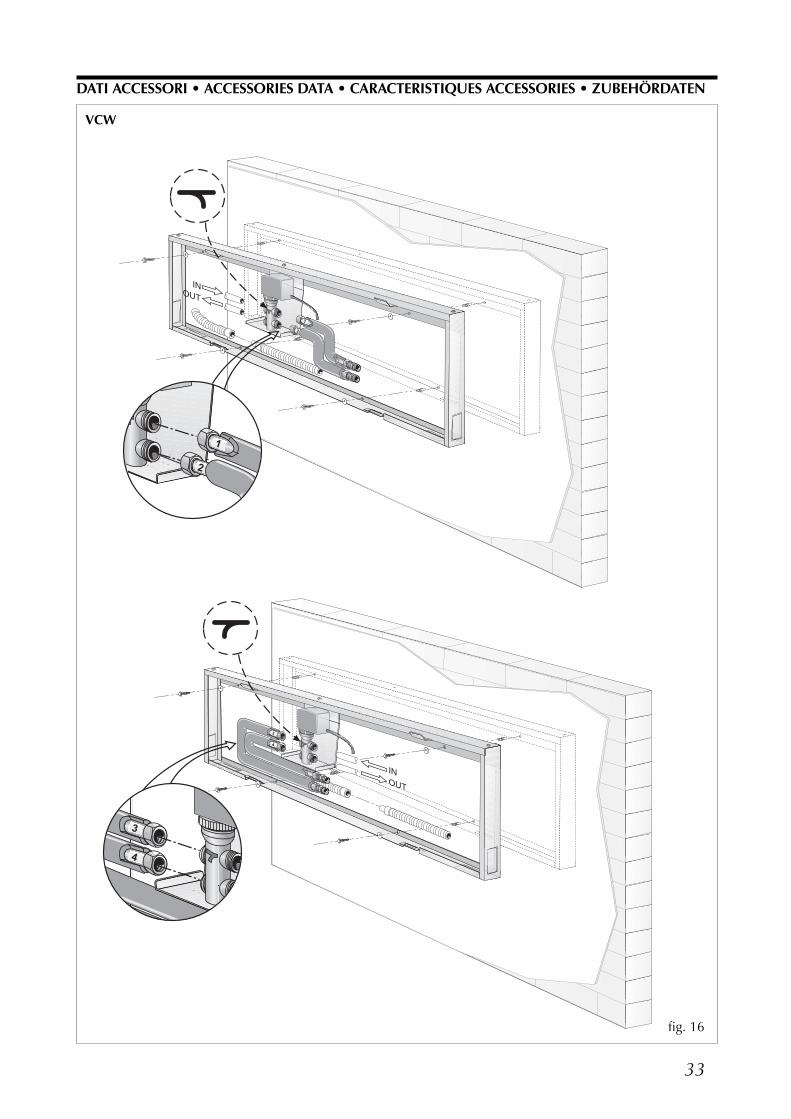
33
�
�
�
�
�����
VCW
DATI ACCESSORI • ACCESSORIES DATA • CARACTERISTIQUES ACCESSORIES • ZUBEHÖRDATEN
�
�
�
�
�����
fig. 16

34
�
�
�
�
�����
�
�
�
�
�����
INSTALLAZIONE CON TUBI CURVI AD “S”INSTALLATION WITH "S" BEND PIPESINSTALLATION AVEC TUYAUX COURBES À "S"INSTALLATION MIT "S"-FÖRMIG GEKRÜMMTENROHREN
INSTALLAZIONE CON TUBI CURVI AD “J”INSTALLATION WITH "J" BEND PIPESINSTALLATION AVEC TUYAUX COURBES À "J"INSTALLATION MIT "J"-FÖRMIG GEKRÜMMTENROHREN
DATI ACCESSORI • ACCESSORIES DATA • CARACTERISTIQUES ACCESSORIES • ZUBEHÖRDATEN
VCW C
VCW V
fig. 17
fig. 18

35
��� �������
���
��
�� ��� ��
����
���
�������� ��
��
��
��
��
�����������
��� ���
DATI DIMENSIONALI • DIMENSIONS • DIMENSIONS • ABMESSUNGEN [mm]
�
� �
≥65
≥50
1900
÷ 2
200
≥1500
≥50
fig. 19
fig. 22
fig. 20
SPAZI TECNICI • TECHNICAL SPACE • ESPACES TECHNIQUES • WANDABSTÄNDE [mm]
DIMENSIONI • DIMENSIONS [mm]DIMENSIONS • ABMESSUNGEN [mm]
A B C
FCW20 795 178 270
FCW30 795 178 270
FCW40 1200 210 320
fig. 21

36
GI = Ionizzatore • Ion generatorGénerateur d’ions • Ionengenerator
F = Fusibile • Fuse • Fusible • Schmelzsicherung
IG = Interuttore magnetotermico • Main switchInterrupteur général • Hauptschalter
IL = Interuttore Acceso/Spento • On/Off switch Interrupteur Allumé/Eteint • ON/OFF Schalter
IR = Ricevitore infrarosso • I.R. ReceiverRécepteur I.R. • Infrarotempfänger
LM = Motore alette deflettrici • Deflector fins motorMoteur ailettes de déflexion • Rippensteuerungsmotor
M = Morsettiera • Terminal boardBoitier • Klemmleiste
MV = Motore ventilatore • Fan motorMoteur ventilateur • Ventilatormotor
PE = Collegamento di terra • Ground connectionPrise de terre • Erdanschluß
SA = Sonda ambiente • Room sensorSonde ambiante • Raumtemperaturfühler
SC = Scheda di controllo • Electronic control boardPlatine de contrôle • Steuerplatine
SD = Sonda temperatura acquaWater temperature sensorSonde temperature eauWassertemperaturfühler
SW = Pulsante di emergenza • Emergency pushbuttonBouton d’urgence • Notschalter
TR = Trasformatore • TransformerTransformateur • Transformator
VS = Valvola solenoide • Solenoid valveVanne solenoide • MagnetventilComponenti non forniti • Components not suppliedComposants non fournis • Nicht lieferbare TeileCollegamenti da eseguire in locoOn-site wiringRaccordements à effectuer in situVor Ort auszuführende Anschlüsse
BI = Bianco • White • Blanc • WeissBL = Blu • Blue • Bleu • BlauMA = Marrone • Brown • Marron • BraunNE = Nero • Black • Noir • SchwarzRO = Rosso • Red • Rouge • Rot
SCHEMI ELETTRICI • WIRING DIAGRAMS • SCHEMAS ELECTRIQUES • SCHALTPLÄNE
LEGENDA • READING KEY • LEGENDE • LEGENDE
���
�
��
�� � !"�
�
!�
�
��"
"�
!�� �����
!#!�� �����
!�� �������
����$
�$�
!�
�$�
% ���
��
�"
���������
�$� �$�
�! "�&���$
'��$
�&�
� (
�%� �%�
!
�&�
��
" $
�� ��
" $
�����%)
��
����� ��"*�$*
&�
��
�
�$
�"
!+,--./0�12+23
$"
"�4�"25�(-,,6��4��.6�,�(-,,6%�4�%.0��(-,,6
���
�*
�
���* ����$'���
fig. 23
N.B. = Per inserire un TIMER ON-OFF, togliere il ponte 5 - 6 e collegare il timer.Note = To connect an ON-OFF TIMER, disconnect the bridge 5 - 6 and then connect the timer.N.B. = Pour l’insertion du TIMER ON-OFF lever le pont 5 - 6 et brancher le timer.Anmerkung = Um einen EIN-AUS TIMER anzuschliessen, die brücke 5 - 6 entenehnem und dann den Timer verbinden.
FCW 20FCW 30

37
�
���"�
!�!#
�
��
��
" $
�� ��
" $
�����%)
��
�
�
$* $"
���
�*
��
���* ����$'���
*����'
�
!"�
���
���
� �
� " � " ��$
�$�
�$�
! �
��$7�"�7��
�!
7�
�����$
8$
7�
%���"
%�������� �9
��&���&�
���* *���'
�%�
�%�
$*
$*
� � � �
������%)
� � � � � �
���
�����
������
�� �
� ������
FCW 40
FCW 20FCW 30
FCW 40
fig. 24
fig. 26fig. 25

38
TRASPORTO • CARRIAGE • TRANSPORT • TRANSPORT
123456
35 Kg
NON bagnare • Do NOT wetCRAINT l’humidité • Vor Nässe schützen
NON lasciare gli imballi sciolti durante il trasportoDo NOT leave loose packages during transportATTACHER les emballages pendant le transport
Die Verpackungen nicht ungesichert transportieren
Sovrapponibilità: controllare sull’imballo la posizione della freccia perconoscere il numero di macchine impilabili
Stacking: control the packing for the arrow position to know the num-ber of machines that can be stacked
Empilement: vérifier sur l’emballage la position de la flèche pour con-naître le nombre d’appareils pouvant être empilés
Stapelung: Anhand der Position des Pfeiles an der Verpackung kontrol-lieren, wieviele Geräte stapelbar sind
NON calpestare • Do NOT trampleNE PAS marcher sur cet emballage • Nicht betreten
NON trasportare la macchina da soli se il suo peso supera i 35 Kg.DO NOT handle the machine alone if its weight is over 35 Kg.
NE PAS transporter tout seul l’appareil si son poids dépasse 35 Kg.Das Gerät NICHT alleine tragen, wenn sein Gewicht 35 Kg überschreitet.
SIMBOLI DI SICUREZZA • SAFETY SYMBOL • SIMBOLES DE SECURITE • SICHERHEITSSYMBOLE
Pericolo: Pericolo: Pericolo!!!Tensione Organi in movimento
Danger: Danger: Danger!!!Power supply Movings parts
Danger: Danger: Danger!!!Tension Organes en mouvement
Gefahr ! Gefahr ! Gefahr!!!Spannung Rotierende Teile

S E R V I Z I A S S I S T E N Z A I TA L I AVALLE D’AOSTAAOSTA D.AIR di Squaiella D. & Bidoggia C. snc Via Chambery 79/7 - 10142 Torino 0117 708 112PIEMONTEALESSANDRIA - ASTI - CUNEO BELLISI s.r.l. Corso Savona, 245 - 14100 Asti 0141 556 268BIELLA - VERCELLI LOMBARDI SERVICES s.r.l. Via delle Industrie - 13856 Vigliano Biellese (BI) 0158 113 82NOVARA - VERBANIA (tutta la gamma esclusi split system) AIR CLIMA SERVICE di F. & C. s.a.s. Via Pertini, 9 - 21021 Angera (VA) 0331 932 110 NOVARA - VERBANIA (solo split system) CI. Elle Clima snc di Benvegnù L. Via S. Anna, 6 - 21018 Sesto Calende (VA) 0331 914 186
TORINO AERSAT TORINO snc di Borioli Secondino & C. Strada Bertolla, 163 - 10156 Torino 0115 611 220D.AIR di Squaiella D. & Bidoggia C. snc Via Chambery 79/7 - 10142 Torino 0117 708 112
LIGURIAGENOVA BRINZO ANDREA Via Del Commercio, 27 1/C2 - 16167 Genova Nervi 0103 298 314IMPERIA AERFRIGO di A. Amborno e C. s.n.c . Via Z. Massa, 152/154 - 18038 Sanremo (IM) 0184 575 257LA SPEZIA TECNOFRIGO di Veracini Nandino Via Lunense, 59 - 54036 Marina di Carrara (MS) 0585 631 831SAVONA CLIMA COLD di Pignataro D. Via Risorgimento, 11 - 17031 Albenga (SV) 0182 511 76LOMBARDIABERGAMO ESSEBI di Sironi Bruno e C. sas Via Pacinotti, 98 - 24100 Bergamo 0354 536 670BRESCIA TERMOTEC. di Vitali G. & C. s.n.c. Via G. Galilei - Trav. I°, 2 - 25010 S. Zeno S. Naviglio (BS) 0302 160 812COMO - SONDRIO - LECCO PROGIELT di Libeccio & C. s.r.l. Via Rigamonti, 21 - 22020 San Fermo della Battaglia (CO) 0315 364 23CREMONA MORETTI ALBANO & C. s.n.c. Via Manini, 2/C - 26100 Cremona 0372 461 935MANTOVA F.LLI COBELLI di Cobelli Davide & C. s.n.c. Via Tezze, 1 - 46040 Cavriana (MN) 0376 826 174
CLIMA CONFORT di O. Mazzoleni Via A. Moro, 113 - 20097 S. Donato Milanese (MI) 0251 621 813
MILANO - LODI - Zona cremasca CLIMA LODI di Sali Cristian Via Felice Cavallotti, 29 - 26900 Lodi 0371 549 304CRIO SERVICE s.r.l. Via Gallarate, 353 - 20151 Milano 0233 498 280S.A.T.I.C. di Lovato Dario Via G. Galilei, 2 int. A/2 - 20060 Cassina dè Pecchi (MI) 0295 299 034
PAVIA BATTISTON GIAN LUIGI Via Liguria, 4/A - 27058 Voghera (PV) 0383 622 53VARESE (tutta la gamma esclusi split system) AIR CLIMA SERVICE di Frascati Paolo & C. snc Via Pertini, 9 - 21021 Angera (VA) 0331 932 110 VARESE (solo split system) CI. Elle Clima snc di Benvegnù L. Via S. Anna, 6 - 21018 Sesto Calende (VA) 0331 914 186 TRENTINO ALTO ADIGEBOLZANO - TRENTO SESTER F. s.n.c. di Sester A. & C. Via E. Fermi, 12 - 38100 Trento 0461 920 179FRIULI VENEZIA GIULIAPORDENONE CENTRO TECNICO s.n.c. di Menegazzo G. & C. Via Conegliano, 94/A - 31058 Susegana (TV) 0438 450 271TRIESTE - GORIZIA LA CLIMATIZZAZIONE TRIESTE SRL Strada della Rosandra, 269 - 34018 San Dorligo della Valle(TS) 0408 280 80UDINE S.A.R.E. di Musso Dino Corso S. Valentino, 4 - 33050 Fraforeano (UD) 0432 699 810VENETOBELLUNO FONTANA SOFFIRO FRIGORIFERI s.n.c. Via Sampoi, 68 - 32020 Limana (BL) 0437 970 042LEGNAGO DE TOGNI STEFANO Via De Nicoli, 2 - 37045 Legnago (VR) 0442 203 27PADOVA CLIMAIR s.a.s. di F. Cavestro & C. Via Austria, 21 - Z.I. - 35127 Padova 0497 723 24ROVIGO FORNASINI MAURO Via Sammartina, 18/A - 44040 Chiesuol del Fosso (FE) 0532 978 450TREVISO CENTRO TECNICO di Menegazzo s.r.l. Via Conegliano, 94/A - 31058 Susegana (TV) 0438 450 269VENEZIA (zona centro città) SIMIONATO GIANNI Via Trento, 29 - 30174 Mestre (VE) 0419 598 88 VENEZIA (provincia escluso il centro città) S.M. s.n.c. di Spolaore Andrea e Musner Maurizio Via Fapanni 41/D - 30030 Martellago (VE) 0415 402 047 VERONA (escluso LEGNAGO) ALBERTI FRANCESCO Via Tombetta, 82 - 37135 Verona 0455 094 10VICENZA (solo split system) ASSICLIMA di Colpo Donato Via Capitello, 63/c - 36010 Cavazzale (VI) 3368 139 63 VICENZA (tutta la gamma esclusi split system) BIANCHINI GIOVANNI & IVAN snc Via G. Galilei, 1Z - Loc. Nogarazza - 36057 Arcugnano (VI) 0444 569 481 EMILIA ROMAGNABOLOGNA EFFEPI s.n.c. di Ferrazzano & Proto Via I° Maggio, 13/8 - 40044 Pontecchio Marconi (BO) 0516 781 146FERRARA FORNASINI MAURO Via Sammartina, 18/A - 44040 Chiesuol del Fosso (FE) 0532 978 450FORLÌ - RAVENNA - RIMINI ALPI GIUSEPPE Via N. Copernico, 100 - 47100 Forlì 0543 725 589MODENA (zona Modena Sud) AERSAT s.n.c. di Leggio M. & Lolli S. Piazza Beccadori, 19 - 41057 Spilamberto (MO) 0597 829 08 MODENA (zona Modena Nord) CLIMASERVICE di Golinelli Stefano Via Per Modena, 18/E - 41034 Finale Emilia (MO) 0535 921 56
PARMA ALFATERMICA s.n.c. Galbano & Biondo Via Mantova, 161 - 43100 Parma 0521 776 771BENASSI GRAZIANO Via Paisello, 8 - 43100 Parma 0521 460 744
PIACENZA MORETTI ALBANO & C. s.n.c. Via Manini, 2/C - 26100 Cremona 0372 461 935REGGIO EMILIA ECOCLIMA S.r.l. Via Maestri del lavoro, 14 - 42100 Reggio Emilia 0522 558 709TOSCANAAREZZO CLIMA SERVICE ETRURIA s.n.c. Via G. Caboto, 69/71/73/75 - 52100 Arezzo 0575 900 700FIRENZE - PRATO S.E.A.T. SERVIZI TECNICI srl Via Aldo Moro, 25 - 50019 Sesto Fiorentino (FI) 0554 255 721GROSSETO ACQUA e ARIA SERVICE s.r.l. Via D. Lazzaretti, 8A - 58100 Grosseto 0564 410 579LIVORNO - PISA SEA s.n.c. di Rocchi R. & C. Via dell’Artigianato, Loc.Picchianti - 57121 Livorno - 0586 426 471LUCCA - PISTOIA FRIGOTEC. s.n.c. G. & MC. BENEDETTI Via V. Civitali, 2 - 55100 Lucca 0583 491 089MASSA CARRARA TECNOFRIGO di Veracini Nandino Via Lunense, 59 - 54036 Marina di Carrara (MS) 0585 631 831SIENA (tutta la gamma esclusi split system) FRIGOTECNICA SENESE s.n.c. di B. & C. Strada di Cerchiaia, 42 - Z.A. 53100 Siena 0577 284 330 SIENA (split system) GLOBAL IMPIANTI SENESE srl Strada Massetana Romana, 52 - 53100 Siena 0577 247 406 MARCHEANCONA - PESARO AERSAT snc di Marchetti S. & Sisti F. Via M. Ricci, 16/A - 60020 Palombina (AN) 0718 894 35MACERATA - ASCOLI PICENO CAST s.n.c. di Antinori-Cardinali & R. Via D. Alighieri, 68 - 62010 Morrovalle (MC) 0733 865 271UMBRIAPERUGIA A.I.T. s.r.l. Via dell’industria, Z.I. Molinaccio - 06154 Ponte S. Giovanni (PG) 0755 990 564TERNI CAPOCCETTI OTELLO Via G. Medici, 14 - 05100 Terni 0744 277 169ABRUZZOCHIETI - PESCARA - TERAMO PETRONGOLO DINO Via Torremontanara, 30 - 66010 Torre Vecchia Teatina (CH) 0871 360 311L’AQUILA - ISERNIA - CAMPOBASSSOLAZIOFROSINONE - LATINA MASTROGIACOMO AIR SERVICE - M. C. P.zza Berardi, 16 - 03023 Ceccano (FR) 0775 601 403RIETI CAPOCCETTI OTELLO Via G. Medici, 14 - 05100 Terni 0744 277 169
(solo split system) DUEG CLIMA di Giulio Giornalista Via Chitignano, 12B - 00138 Roma 0688 130 20 ROMA (solo split system) MARCHIONNI MARCO P.zza dei Bossi, 16 - 00172 Centocelle (RM) 0623 248 850
(tutta la gamma esclusi split system)TAGLIAFERRI 2001 s.r.l. Via Guidonia Montecelio snc - 00191 Roma 0633 312 34 VITERBO AIR FRIGO di Massimo Piacentini Viale Baccelli, 74 - 00053 Civitavecchia (RM) 0766 541 945CAMPANIAAVELLINO - SALERNO SAIT s.r.l. Via G. Deledda, 10 - 84010 San Marzano sul Sarno (SA) 0815 178 451CAPRI CATALDO COSTANZO Via Tiberio, 7/F - 80073 Capri (NA) 0818 378 479NAPOLI - CASERTA - BENEVENTO AERCLIMA Sud s.n.c. di Fisciano Carmelo & C. Via Nuova Toscanella, 34/c - 80145 Napoli 0815 456 465PUGLIABARI KLIMAFRIGO s.r.l. Via Vallone, 81 - 70121 Bari 0805 538 044FOGGIA CLIMACENTER di Amedeo Nardella Via Carmicelli, 29 Pal. A Sc. A - 71016 San Severo (FG) 3396 522 443LECCE - BRINDISI GRASSO VINCENZO Zona P.I.P. - Lotto n. 38 - 73052 Parabita (LE) 0833 595 267TARANTO ORLANDO PASQUALE Via Vespucci, 5 - 74023 Grottaglie (TA) 099 5 639 823BASILICATAMATERA - POTENZA AERLUCANA di A. Scalcione Via Dei Peucezi, 23 - 75100 Matera 0835 381 467MOLISECAMPOBASSO - ISERNIA PETRONGOLO DINO Via Torremontanara, 30 - 66010 Torre Vecchia Teatina (CH) 0871 360 311CALABRIACATANZARO - COSENZA - CROTONE A.E.C. di Ranieri Annarita Via B. Miraglia, 72 - 88100 Catanzaro 0961 771 123REGGIO CALABRIA REPACI ANTONINO Via Militare 2nda Trav. 8D - 89053 Catona (RC) 0965 301 431REGGIO CALABRIA - VIBO VALENTIA MANUTENSUD di Antonio Amato Via F. Cilea, 62 - 88065 Guardavalle (CZ) 0967 865 16SICILIACATANIA - MESSINA GIUFFRIDA GIUSEPPE Via Mandrà, 15/A - 95124 Catania 0953 514 85ENNA - CALTANISSETTA - AGRIGENTO FONTI FILIPPO Viale Aldo Moro, 141 - 93019 Sommatino (CL) 0922 871 333PALERMO - TRAPANI S.E.A.T. di A. Parisi & C. s.n.c. Via T. Marcellini, 7 - 90135 Palermo 0915 917 07SIRACUSA - RAGUSA FINOCCHIARO ANTONINO Via Paternò, 71 - 96100 Siracusa 0931 756 911SARDEGNACAGLIARI - ORISTANO MUREDDU L. di Mureddu Pasquale Via Garigliano, 13 - 09122 Cagliari 0702 846 52SASSARI - NUORO POSADINU SALVATORE IGNAZIO Z.I. Predda Niedda - Sud - Strada 11 - 07100 Sassari 0792 612 34
�������������� ���������� ���������������� ��������
��� ���������������������� ��������������������� ������������� �!���"
�����������������#�� �!��������$�� ����������� ������������� �"

I dati tecnici riportati nella presente documentazione non sono impegnativi.AERMEC S.p.A. si riserva la facoltà di apportare in qualsiasi momentotutte le modifiche ritenute necessarie per il miglioramento del prodotto.Les données mentionnées dans ce manuel ne constituent aucun engage-ment de notre part. Aermec S.p.A. se réserve le droit de modifier à tousmoments les données considérées nécessaires à l’amelioration du produit.
Technical data shown in this booklet are not binding.Aermec S.p.A. shall have the right to introduce at any time whatevermodifications deemed necessary to the improvement of the product.Im Sinne des technischen Fortsschrittes behält sich Aermec S.p.A. vor,in der Produktion Änderungen und Verbesserungen ohneAnkündigung durchzuführen.
AERMEC S.p.A.37040 Bevilacqua (VR) - ItaliaVia Roma, 44 - Tel. (+39) 0442 633111Telefax (+39) 0442 93730 - (+39) 0442 93566www .aermec. com - info @aermec. com
Aermec partecipa al Programma diCertificazione EUROVENT.
I prodotti interessati figurano nella GuidaEUROVENT dei Prodotti Certificati.
Aermec is partecipating in the EUROVENTCertification Programme.
Products are as listed in the EUROVENTDirectory of Certified Products.
Aermec partecipe au Programme deCertification EUROVENT.
Les produits figurent dans l’AnnuaireEUROVENT des Produits Certifiés.
Aermec ist am Zertifikations - ProgrammEUROVENT beteiligt.
Die entsprechend gekennzeichneten Produktesind im EUROVENT - Jahrbuch aufgefürt.
��������� � ���� �� ���� �� �� �� ������ ���� �� �� �� ��������� ���������������������� ��������������������� ������������� �!���"���� ���������� ���#� � �!���� �� ��$� � �� ��� ������ �� ����� ������ �"