Embed Size (px)
Citation preview
S-19-01-1214-UV101 V1.3
VECTOR LiTTLE BEAVER 2.0
ULTRASONIC SCALER (25/30K)
Instruction For Use
VECTOR R & D INC.
6824 19TH ST#230 UNIVERSITY PLACE
WA 98466 USA Web: www.vectorusa.net
User Manual

S-19-01-1214-UV101 V1.3 2
Table Of Contents
Section Section Title Page
Number Description of Contents Number
1 Precautions……………………………………………………………………………………………..3
1.1 Precautions for All Systems
1.2 Precautions for Ultrasonic Prophylaxis Procedure
2 Introduction…………………………………………………………………………………………....4
3 Application………………………………………………………………………………………………4
4 Specification………………………………………….………………………………………………...5
5 Contraindications and Warnings…………………………………………………………………6
5.1 Contraindications
5.2 Warnings
6 Infection Control……………………………………………………………………………………….6
6.1 General Infection Control Recommendations
6.2 Water Supply Recommendations
7 Installation Instructions……………………………………………………………………………7
7.1 General Information
7.2 Water Line Requirements
7.3 Electrical Requirements
7.4 Unpacking the System
7.5 System Installation
7.6 Vertical Installation
7.7 Rear Panel Controls / Power Connection
7.8 Water Supply Line Connection
8 Little Beaver 2.0 Ultrasonic Scaler Description……………………………………………8-9
8.1 System Controls
8.2 Handpiece Holder
8.3 Ultrasonic Insert, Handpiece Sleeve Assembly/Disassembly
8.4 Foot Switch Controls and Operation
9 Accessories……………………………………………………………………………………….……..10
10 Techniques For Use……………………………………………………………………………………10
10.1 Patient Positioning
10.2 Performing Ultrasonic Scaling Procedures
10.3 Patient Comfort Considerations
11 System Maintenance And Care…………………………………………………………………….11
12 Trouble shooting……………………………………………………………………………………….12
13 Disposable of Unit……………………………………………………………………………………..13
14 Disclaimer………………………………………………………………………………………………..13
15 WARRANTY………………………………….…………………………………………………………..14
16 Additional Symbols…………………….……………………………………………………………..15

S-19-01-1214-UV101 V1.3 3
Section 1: Precautions
Prior to installation and start-up of the ultrasonic scaler, carefully read the instructions provided herein!
1.1 Precautions for All Systems
Do not place the ultrasonic scaler on or next to a radiator or other heat source. Excessive heat may
damage the ultrasonic scaler’s electronics. Place the ultrasonic scaler where air is free to circulate on all sides
and beneath it. Do not cover vents on rear panel.
The ultrasonic scaler which can be carried vertical or plate is portable, but must be handled with care
when moving.
Equipment flushing and dental water supply system maintenance are strongly recommended. See
Section 11: System Maintenance And Care.
Close the water shut-off valve in the dental water supply system every night before leaving the office.
The use of an in-line water filter is recommended.
Never operate the ultrasonic scaler without water flowing through the handpiece.
Grounding reliability can only be achieved when the equipment is connected to an equivalent
receptacle marked Hospital Only or Hospital Grade.
1.2 Precautions for Ultrasonic Prophylaxis Procedures
‧ Like a toothbrush, ultrasonic inserts "wear out" with use. Inserts with just 2 mm of wear lose about 50%
of their scaling efficiency. In general, it is recommended that ultrasonic inserts be discarded and replaced
after one year of use to maintain optimal efficiency and avoid breakage.
‧ If excessive wear is noted, or the insert has been bent, reshaped or otherwise damaged, discard the
insert immediately.
‧ Ultrasonic insert tips that have been bent, damaged, or reshaped are susceptible to in-use breakage and
should be discarded and replaced immediately.
‧ Retract the lips, cheeks and tongue to prevent contact with the insert tip whenever it is placed in the
patient's mouth.

S-19-01-1214-UV101 V1.3 4
Section 2: Introduction
2.1 Function:
The Little Beaver 2.0 Ultrasonic Scaler is designed
for use in prophylaxis treatments periodontia, and
other areas of operative dentistry. When used
in prophylaxis treatment, the unit operates with a
fine warm water spray, requiring little of the physical
exertion necessary with hand instruments. It easily
and effectively removes stubborn calculus and
stains both supragingivally and subgingivally,
leaving crown and root surfaces clean and smooth.
2.1 Conformance to Standards:
The Vector R & D Inc. Little Beaver 2.0 Ultrasonic
Scaler conforms to IEC60601-1-2:2007 and
IEC60601-1-1:2005.
The device is CE marked corresponding to European
Medical Device Directive (93/42/EEC)
2.2 Supplies and Replacement Parts
Contact your local Vector R & D Inc. dealer to order
supplies or replacement parts. There are no
serviceable parts included in this device. Please
contact your dealer to acquire all repairing service
and technique supports.
CAUTIONE: QUIPMENT NOT SUITABLE FOR
USE IN THE PRESENCE OF FLAMMABLE
ANESTHETIC MIXTURE WITH AIR OR WITH
NITROUS OXIDE.
CAUTION: U.S FEDERAL LAW RESTRICTS THIS
DEVICE TO SALE BY OR ON THE ORDER OF A
DENTAL PROFESSIONAL.
Section 3: Application
The Ultrasonic Scaler procedures
‧ All general supra and subgingival scaling applications.
‧ Periodontal debridement for all types of periodontal diseases.
‧ Endodontic procedures.
S-19-01-1214-UV101 V1.3 5
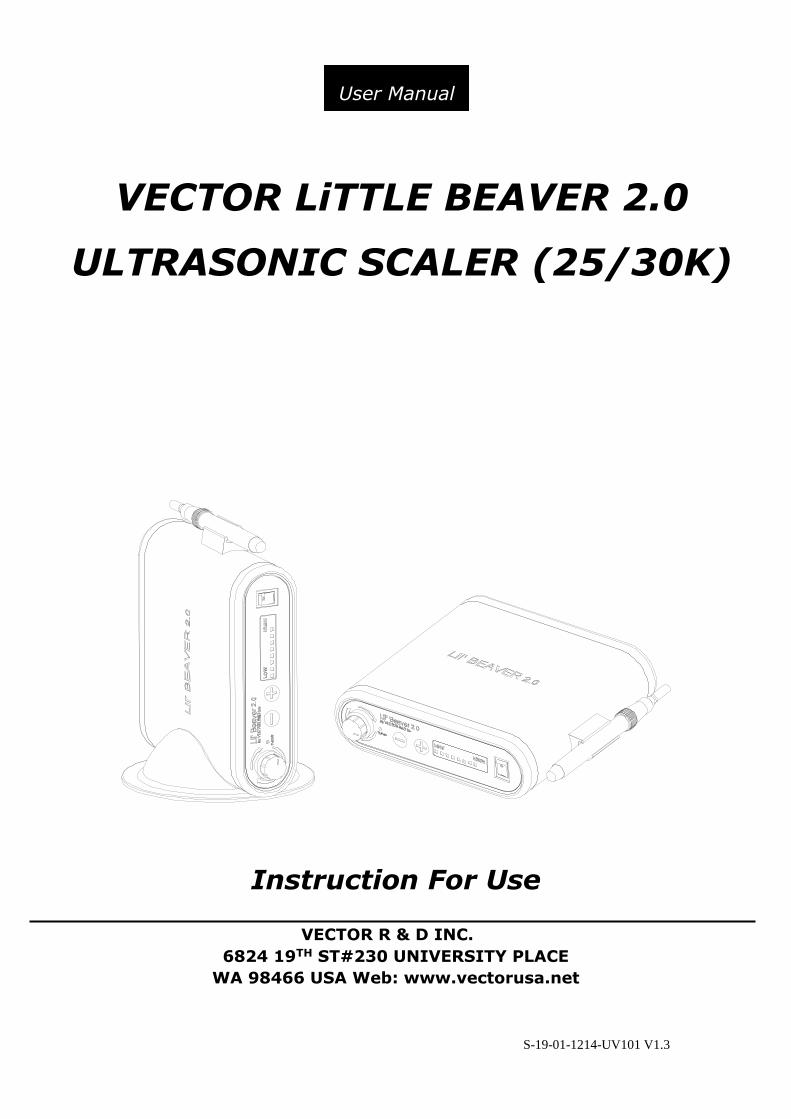
Section 4: Specifications
Vector R & D Inc. Little Beaver 2.0 Ultrasonic
Scaler is multi-voltage 110V/230V unit.
4.1 Electric Voltage:
VOLTAGE: CURRENT
100VAC 50/60Hz 1.0 A (MAX)
110VAC 50/60Hz 1.0 A (MAX)
230VAC 50/60Hz 0.6 A (MAX)
WATTAGE: MAX.85 W
WATER PRESSURE: 20-40 psi
4.2 Dimension:
HEIGHT : 6.5 CM
WIDTH : 23.0 CM
DEPTH : 22.0 CM
WEIGHT : 2.1 KG
4.3 Operation Environment:
AMBIENT TEMPERATURE :+10℃ - +40℃
RELATIVE HUMIDITY :30% - 75%
ATOMOSPHERIC PRESSURE :700 hPa - 1060hPa
4.4 Transportation And Storage Environment:
AMBIENT TEMPERATURE : -10 °C ~+70 °C
RELATIVE HUMIDITY : 10%~90%
ATOMOSPHERIC PRESSURE : 500 hPa ~1060 hPa

S-19-01-1214-UV101 V1.3 6
Section 5: Contraindications and Warnings
5.1 Contraindications
‧ Ultrasonic Systems should not be used for
restorative dental procedures involving the
condensation of amalgam.
‧ This device is designed to work with all Cavitron®
(remark) insert with 25Khz or 30Khz frequency
automatically. For optimum performance please
use only qualified inserts supplied by Cavitron® or
Rolence® .
‧ Do not use this device if the patient or operator is
wearing a pacemaker.
Remark: Cavitron® is a registered trademark of
Dentsply® International, Inc
5.2 Warnings
‧ Persons who are fitted with cardiac pacemakers,
defibrillators and other active implanted medical
devices, have been cautioned that some types of
electronic equipment might interfere with the
operation of the device. We recommend that the
handpiece and tubing be kept at least 6 to 9
inches (15 to 23 cm) away from any device and
their leads during use.
‧ During using the unit, make sure that water is
flowing continuously. If the handpiece overheats
please check the water supply, and stop using the
unit for a while.
Section 6: Infection Control
6.1 General Infection Control
Recommendations
‧ As with all dental procedures, the use of standard
personal protection equipment (i.e., wearing a
face mask, eyewear, or face shield, gloves and
protective gown) is recommended.
‧ For maximal operator and patient safety, carefully
follow section 11 system maintenance and care
information detailed in the operating instruction
accompanying your ultrasonic scaler.
‧ As with high speed handpieces, and other dental
devices, the combination of water and ultrasonic
vibration from your ELiTEDENT® Ultrasonic Scaler
will create aerosols. With proper technique, much
of the aerosol dispersion can be effectively
controlled and minimized. Please carefully follow
the procedural guidelines in this manual
regarding the use of your ultrasonic scaler.
‧ Always flush your ELiTEDENT® Ultrasonic Scaler
with highest flow before treatment. Refer to more
information in section 10.
‧ Clean and disinfect the handpiece sleeve between
patients. The handpiece sleeve can be autoclaved
up to 135℃ for at least 3 minutes.
Sterilizing:
1. Place handpiece sleeve and pouched ultrasonic
insert into a steam autoclave. After warm-up is
completed, operate at a sterilizing temperature
and pressure of 273° F/31 psi (134°C/216 kPa)
for 12 minutes, followed by a 20-30 minute
drying time.
2. To maintain sterility, the insert should remain in
the sealed pouch until it is ready for use.
DO NOT USE Cold sterilization solution.
6.2 Water Supply Recommendations
‧ It is highly recommended that all dental water
supply systems should conform to applicable CDC
(Centers for Disease Control and Prevention) and
ADA (American Dental Association) standards,
and that all recommendations be followed in
terms of flushing, chemical flushing, and general
infection control procedures. See sections 6.1 and
11.
S-19-01-1214-UV101 V1.3 7
Section7: Installation Instructions
7.1 General Information
If installation of your Little Beaver 2.0 ultrasonic
scaler is performed by someone other than
trained Vector R & D Inc. distributor personnel,
care should be taken to observe the following
requirements and recommendations.
7.2 Water Line Requirements
‧ The System's water supply line is factory installed.
Do not disconnect from the ultrasonic scaler.
‧ Incoming water supply line pressure to the
ultrasonic scaler must be 25 psi (172 kPa
minimum) to 40 psi (276 kPa) maximum. If your
dental water system's supply line pressure is
above 60 psi, install a water pressure regulator on
the water supply line to your ultrasonic scaler.
‧ A manual shut-off valve on the dental water
system supply line should be used so that the
water can be completely shut-off when the office
is unoccupied.
‧ A filter in the dental water system supply line is
recommended so that any particles in the water
supply will be trapped before reaching the
ultrasonic scaler.
‧ After the above installations are completed on the
dental water supply system, the dental office
water line should be thoroughly flushed prior to
connection to the System.
‧ After flushing system verify there are no leaks.
7.3 Electrical Requirements
Refer to Section 3: Specifications.
7.4 Unpacking the System
Carefully unpack your Little Beaver 2.0 ultrasonic
scaler and verify that all components and
accessories are included:
1. Little Beaver 2.0 Ultrasonic scaler main unit
with factory installed water supply line and
handpiece assembly with tubing.
2. Detachable AC Power Cord.
3. Foot Control Switch.
4. User Direction Manual.
5. Ultrasonic Inserts (Optional).
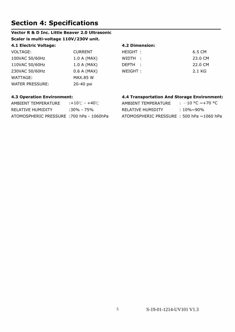
7.5 System Installation
‧ The Little Beaver 2.0 Ultrasonic Scaler is designed
for both horizontal and vertical placement on a
level surface. Refer to section 7.6 for more
information of vertical installation.
‧ Be sure unit is stable and resting on four feet.
‧ Placing unit in direct sunlight may discolor plastic
housing.
7.6 Vertical Installation
7.7 Rear Panel Controls / Power Connection
‧ The ON/OFF Control Switch and power indicator is
located on the Front Panel of the Little Beaver 2.0
Ultrasonic Scaler. (See Section 8.1)
‧ Verify the ON/OFF Control Switch located on the
front panel of the Little Beaver 2.0 ultrasonic
scaler is in the OFF position before proceeding.
‧ Plug the detachable AC Cord into the back of the
ultrasonic scaler and into an approved outlet.
7.8 Water Supply Line Connection
Connect the free end of the ultrasonic scaler’s water
supply line to the dental water supply line. Inspect
all connections to make certain there are no leaks.
S-19-01-1214-UV101 V1.3 8
Section 8: Little Beaver 2.0 Ultrasonic Scaler Description
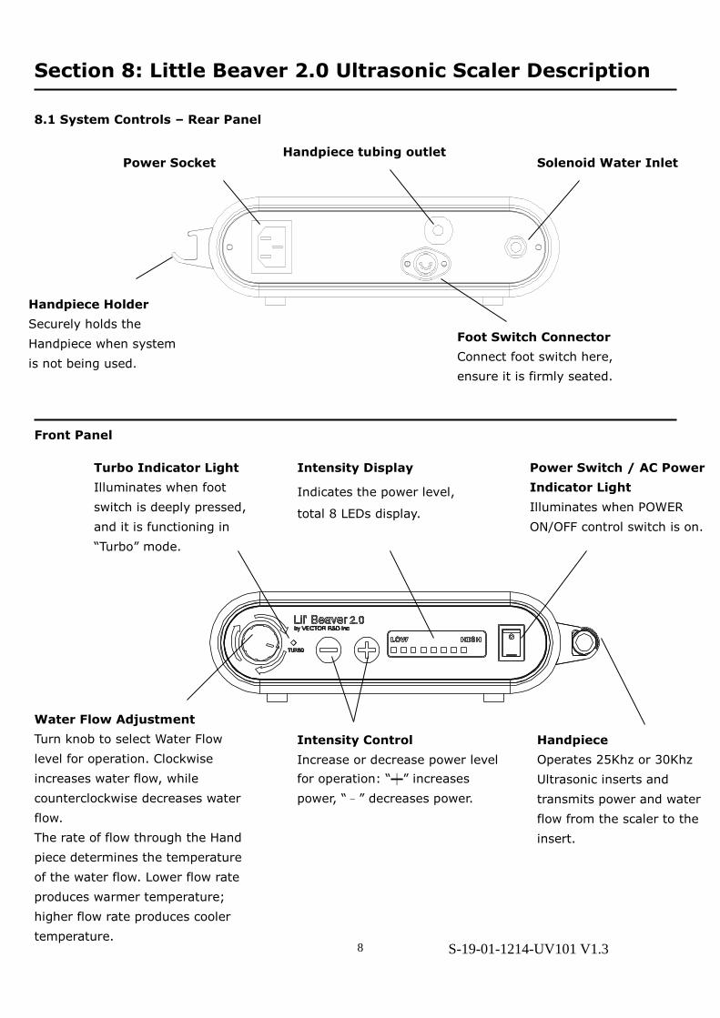
8.1 System Controls – Rear Panel
Front Panel
Water Flow Adjustment
Turn knob to select Water Flow
level for operation. Clockwise
increases water flow, while
counterclockwise decreases water
flow.
The rate of flow through the Hand
piece determines the temperature
of the water flow. Lower flow rate
produces warmer temperature;
higher flow rate produces cooler
temperature.
Foot Switch Connector
Connect foot switch here,
ensure it is firmly seated.
Solenoid Water Inlet Power Socket
Intensity Control
Increase or decrease power level
for operation: “┿” increases
power, “–” decreases power.
Handpiece
Operates 25Khz or 30Khz
Ultrasonic inserts and
transmits power and water
flow from the scaler to the
insert.
Power Switch / AC Power
Indicator Light
Illuminates when POWER
ON/OFF control switch is on.
Handpiece Holder
Securely holds the
Handpiece when system
is not being used.
Intensity Display
Indicates the power level,
total 8 LEDs display.
Handpiece tubing outlet
Turbo Indicator Light
Illuminates when foot
switch is deeply pressed,
and it is functioning in
“Turbo” mode.

S-19-01-1214-UV101 V1.3 9
8.2 Handpiece Holder
When your ultrasonic scaler is set up horizontal, you can choose to installed handpiece holder to the left side
of the main unit if you are a left-handed user.
8.3 Handpiece Assembly / Handpiece Sleeve
The ultrasonic scaler is multi-frequency unit compatible with all Cavitron® 25Khz or 30 Khz inserts. The
system will automatically detect the insert frequency, no need to switch any button.
For more oral hygiene care, the handpiece sleeve can be dismantled and autoclaved. See below:
To take off the handpiece sleeve, please hold the fastening ring, and rotate the sleeve counterclockwise from
handpiece tubing assembly. Note: Avoid rotate or twist the handpiece tubing.
8.4 Foot Switch Controls and Operation
The Foot Switch is a two-position momentary switch, which activates both Ultrasonic energy and water flow
at insert tip.
Foot Switch Released…
Both ultrasonic activation and
irrigating flow stop.
Foot Switch Depressed Half Way
(1st position)
The ultrasonic insert tip is
activated and irrigating water flow
under normal function.
Foot Switch fully depressed
(2ndposition)
This activates the “Turbo” mode
increasing extra power.
Handpiece Sleeve
Enable to dismantle
and autoclave
Fastening Ring
Hold here, rotate handpiece
sleeve to release.
Handpiece tubing assembly
Include handpiece set, tubing
and fastening ring.
O-ring

S-19-01-1214-UV101 V1.3 10
Section 9: Accessories
1. Ultrasonic insert (optional)
2. AC Power Cord Set
3. Foot control switch
4. Water tubing with quick connector
Section10: Techniques For Use
10.1 Patient Positioning
‧ For optimal access to both the upper and lower
arches, the backrest of the chair should be
adjusted to a 45∘ degree angle. This assures
patient comfort and Clinician visibility.
‧ Have the patient turn his/her head to the right or
left. Also position chin up or down depending
upon the quadrant and surface being treated.
Evacuate irrigate using either a saliva ejector or
High Volume Evacuator (HVE).
10.2 Performing Ultrasonic Scaling
Procedures
‧ Note: Refer to the Infection Control Information
Booklet supplied with your system for general
procedures to be followed at the beginning of
each day and between patients.
‧ The edges of ultrasonic inserts are intentionally
rounded so there is little danger of tissue
laceration with proper ultrasonic Scaling
technique. Whenever the insert tip is placed in the
patient’s Mouth, the lips, check and tongue should
be retracted to prevent Accidental prolonged
contact with the activated tip.
‧ Hold the empty Handpiece in an upright position.
Activate the Foot Control until fluid exits.
‧ Lubricate the rubber O-ring on the insert with
water before placing it into the handpiece. Fully
seat insert with a gentle push-twist motion. DO
NOT FORCE IT INTO PLACE.
‧ Activate the System. Hold the handpiece over a
sink or drain. Check spray temperature to verify
fluid is reaching the working end of the insert tip.
Adjust the water cooler irrigate. Control knob to
ensure adequate flow for the selected Power
setting. Greater flow settings provide cooler
irrigation.
‧ It may be necessary to adjust water flow larger
under "Turbo" mode (Foot Control fully depressed)
so adequate fluid will be available to cool tip and
tooth interface.
‧ In general, it is suggested a "feather-light-touch"
be used both supra and subgingivally. The motion
of the activated tip and acoustic effects of the
irrigating fluid, in most cases, is adequate to
remove even the most tenacious calculus.
‧ Periodically check the ultrasonic insert for wear
with the Insert Efficiency Indicator.
‧ The use of a saliva ejector or High Volume
Evacuator (HVE) is recommended during all
procedures.
‧ Set the System's Power Adjustment knob to the
lowest power setting for the application and the
selected insert.
‧ If water leakage found in handpiece, replace
sleeve or o-ring on handpiece cable assembly to
eliminate.
10.3 Patient Comfort Considerations
Reasons for sensitivity
‧ Incorrect tip placement. Point should be directed
away from root surfaces.
‧ Not keeping tip in motion on tooth. Do not allow
the insert to remain in a static position on any one
area of the tooth. Change the insert's path of
motion.
‧ Applying pressure. Use extremely light grasp and
pressure, especially on exposed cementum.
‧ If sensitivity persists, decrease power setting
and/or move from the sensitive tooth to another
and then return.

S-19-01-1214-UV101 V1.3 11
Section11: System Maintenance and Care
Daily Maintenance
It is recommended that you perform the following
maintenance procedures to help minimize bio-film
formation in the water path of your Little Beaver 2.0
ultrasonic scaler which could affect the water flow to
the ultrasonic insert, and scaling performance.
Start-Up Procedures at the beginning of the
day:
1. Open the manual shut-off valve on the dental
office water supply system.
2. Turn the System ON using the Power ON/OFF
switch. (see illustration on page 7) Verify the Power
Indicator Light is on.
3. Set the Power Control knob to minimum setting.
4. Set the Water Control knob to maximum.
5. Hold the Handpiece (without an insert installed)
upright over a sink or drain. Activate the Foot
Control and flush the water line for at least 2
minutes.
6. Place a sterilized insert into the Handpiece and
set the water control knob to your preferred
operating position.
Between Patients:
1. Remove ultrasonic insert and handpiece sleeve
used, clean and sterilize.
2. Clean and disinfect the surfaces of the cabinet,
Power Cord, Handpiece cable assembly*, control
knobs, Foot Control and cable assembly by
applying an approved non-immersion type
disinfectant solution* carefully following the
instructions provided by the disinfectant solution
manufacturer. To clean system, generously spray
disinfectant solution on a clean towel and wipe all
surfaces. Discard used towel. To disinfect system,
generously spray disinfectant on a clean towel
and wipe all surfaces. Allow disinfectant solution
to air dry. Do not spray disinfectant solution
directly on the ultrasonic scaler.
3. Place a sterilized handpiece sleeve. Set power to
minimum. Hold the handpiece over a sink or drain
and flush the water line at maximum water flow
for 30 seconds.
4. When ready, place a sterilized insert into the
handpiece.
5. Please consider use a FDA approved sheath to for
the cable and entire handpiece or at least to cover
the handpiece from the fastening ring to cable
when sleeve is sterilized between patients.
Shut-Down Procedures at the end of the day:
2. Remove ultrasonic insert and handpiece sleeve
used, clean and sterilize.
3. Turn the System OFF.
4. Clean and disinfect the surfaces of the cabinet,
Power Cord, Handpiece cable assembly, control
knobs, Foot Control cable assembly by applying
an approved non-immersion type disinfectant
solution* carefully following the instructions
provided by the disinfectant solution
manufacturer. To clean system, generously spray
disinfectant solution on a dean towel and wipe all
surfaces. Discard used towel. To disinfect system,
generously spray disinfectant on a clean towel
and wipe all surfaces. Allow disinfectant solution
to air dry. Do not spray disinfectant solution
directly on the ultrasonic scaler.
5. Close the manual shut-off valve on the dental
water supply system.
*Note: Those Water-based disinfection solutions
are preferred, due some alcohol-based disinfectant
solutions may be harmful and may discolor plastic
materials.
*Note: The electric wire winding covered by heat
shrinkage tube which protected by handpiece sleeve
is very sensitive to the disinfectant solution and
water. After the disinfection, wipe surface of
shrinkage tube with a slightly damp cloth and dry
thoroughly before use.

S-19-01-1214-UV101 V1.3 12
Section12: Trouble shooting
Although service and repair of the Little Beaver 2.0
Ultrasonic Scaler should be performed by VECTOR R
& D INC. dealer personnel, the following are some
basic trouble shooting procedures that will help
avoid unnecessary service calls. Generally, check all
lines and connections to and from the System, a
loose plug or connection will often create problems.
Check the settings on the System's knobs.
12.1 Troubleshooting Guide
Problem: System will not operate:
(Power Indicator Light is not lit.)
1. Check that the Power switch is in the ON position,
and that the detachable Power Cord is fully seated
in the receptacle on back of System.
2. Check that the System's three-prong plug is fully
seated in an appropriate AC receptacle, and that
AC current is present.
(Power Indicator Light is lit.)
1. Check that the Foot Control Connector is fully
seated in the Foot Control Receptacle on the back
of the System.
System operates:
(No water flow to insert tip.)
1. Assure that water control is properly adjusted.
2. Check that water supply control valve(s) (dental
office water supply) are open.
(Insert stops vibrating)
1. Deactivate foot control.
2. Verify insert is in good condition.
3. Depress foot control to try again.

S-19-01-1214-UV101 V1.3 13
Section 13: Disposal of Unit
‧ Keep original packaging until the Little Beaver 2.0 Ultrasonic Scaler is to be disposed of permanently. You
can use it for shipping or storing your Little Beaver 2.0 Ultrasonic Scaler at any time.
‧ Dispose of the Little Beaver 2.0 Ultrasonic Scaler in accordance with local and national laws.
Section 14: Disclaimer
VECTOR R & D INC considers itself responsible for the effects on safety, reliability and performance of this
product only if:
‧ Assembly operations, extensions, re-adjustments, modifications or repairs are carried out by persons,
authorized by VECTOR R & D INC.
‧ The electrical installation of the relevant room complies with the requirements.
‧ The equipment is used in accordance with these instructions for use.

S-19-01-1214-UV101 V1.3 14
Section 15: Warranty
15.1 Malfunction
Vector R & D Inc. hereby warrants that for a period of one year from the delivery date, this device shall be
free from defects in material and workmanship. In case the machine is found malfunctioned under normal
use, Vector R & D Inc. will offer service of free maintenance and parts for replacement.
15.2 Repair
Repairs must be only carried out by an authorized Vector R & D Inc. engineer/dealer. If repairs during
warranty period are not carried out by an authorized engineer/dealer, warranty will expire immediately.
15.3 Warranty Exception
The warranty stated herein is the sole warranty applicable to Vector R & D Inc. products. Vector R & D Inc.
expressly disclaims the liability for warranty even within warranty period, if
(1) Damages caused by natural disaster.
(2) Operator's fault or wrong operation.
(3) Application use other than curing light-cured material purpose.
(4) A malfunction or damage caused by repair, adjustment, modification which is not carried out by Vector R
& D Inc. authorized technicians/dealers.
(5) A malfunction caused by abnormal power source or voltage.
(6) It is a consumption part.

S-19-01-1214-UV101 V1.3 15
Section 16: Additional Symbols
Caution, Consult accompanying Documents
Read usage instructions
Alternating Current
Manufacturer
Date of manufacture
Catalogue number
Type BF Applied Part; Type BF Equipment - Protection against electric shock
Equipment class: Class II (IEC601-1) - double insulated
The equipment complies with the requirements in the Medical Device
Directive 93/42/EEC.
Icon to identify electric and electronic devices. The unit must be collected and
disposed of separately.
Power off
Power on

S-19-01-1214-UV101 V1.3 16