Embed Size (px)
Citation preview

Virtual Breadboard
Prototype Virtually, Make for Real
www.virtualbreadboard.com
Date Description VBB Version 16 Oct 2012
First Draft Created V 4.19
21 Nov 2012 Enhanced Nets which were broken • Nets are now components • Nets have properties which can be edited • Net dropdown list has accelerator features • Some components V18’O, Arduino etc have
default Nets which match up to their pin names, D0,D1.. A0,A1..
• Show Nets toolbar button show the ‘rats’ nest of selected nets
Windows 8 Compatibility • Removed Xenocode sandbox • Moved ‘Built-in’ examples into
AppData/Virtual Breadboard directory Kits
• Added 1st example Kit ‘Christmas Tree Kit’
V 4.20
24 Nov 2012 Fix for Language Issue V 4.21 30 Nov 2012 Fix for components broken in window 8 changes.
Specifically code components such as TTL74XX V 4.22

22 Aug 2013 Clean up V 4.33

Virtual Breadboard......................................................................................................... 1 Introduction .................................................................................................................... 8 Circuit Emulation ........................................................................................................... 8 System Requirements..................................................................................................... 8 Installation...................................................................................................................... 9
Dependencies ............................................................................................................. 9 Microsoft .NET 2.0 ................................................................................................ 9 Microsoft JSharp Runtime ..................................................................................... 9
Internet Activation ....................................................................................................... 10 Internet Access ..................................................................................................... 10
VBB Application ......................................................................................................... 11 VBB Solution Orientation............................................................................................ 12
1. VBB Application Window ............................................................................... 13
2. VBB Application Menus.................................................................................. 13 Edit ........................................................................................................................... 15 Help Menu ............................................................................................................... 15
About.................................................................................................................... 17 DesignSheet Toolbar ............................................................................................ 18 Current DesignSheet ............................................................................................ 18 The layout toolbar ................................................................................................ 18 The Solution Explorer .......................................................................................... 19
The properties panel ................................................................................................. 21 The property description panel ............................................................................ 21 Empty panel ......................................................................................................... 21 Status Toolbar ...................................................................................................... 21 DesignSheet Toolbox ........................................................................................... 21
New Project Dialog ...................................................................................................... 23 New Tab ................................................................................................................... 23 Existing Tab ............................................................................................................. 26 Recent ...................................................................................................................... 27 Market Place ............................................................................................................ 28 Activating a VBB Feature ........................................................................................ 28
Activating a feature .............................................................................................. 29 Activating multiple features ................................................................................. 30
Shipping ................................................................................................................... 31 Order Processing ...................................................................................................... 31
Design Sheets ............................................................................................................... 32 Standard Edition DesignSheets ................................................................................ 32 Feature Extension DesignSheets .............................................................................. 32
Java Source Code Project Design Sheet ...................................................................... 32 Solution Tree Manager ............................................................................................ 33 Activating Java Source Project ................................................................................ 33
Context Sensitive Functions ................................................................................ 33 Add New Java Source File ................................................................................... 34 Delete ................................................................................................................... 35 Rename ................................................................................................................ 35
Properties ................................................................................................................. 36 Working with ClassPath .......................................................................................... 36

Working with Packages within the Java Source Project .......................................... 38
Design Time Source Editor ...................................................................................... 41 Keyword Highlighting ......................................................................................... 41 Syntax Error Highlighting.................................................................................... 41 Tab Suggestions ................................................................................................... 42 Parameter Suggestions ......................................................................................... 42 Toggle Breakpoints .............................................................................................. 42 Edit Menu, Cut, Copy and Paste Undo ................................................................ 43
Design Time Tabs .................................................................................................... 43 Errors Tab ............................................................................................................ 43 Output Tab ........................................................................................................... 44 Classes.................................................................................................................. 45 Allocation ............................................................................................................. 45
Runtime Tabs ........................................................................................................... 46 Output .................................................................................................................. 46 DebugXmlDoc ..................................................................................................... 46 Interpreting the XML SnapShot View ................................................................. 49
Local Variable Tab .............................................................................................. 51 Toolbar : Java Source Code Project ......................................................................... 53
Emulation Mode................................................................................................... 54 Breadboard DesignSheet .............................................................................................. 56
Toolbar : Breadboard ............................................................................................... 56 DesignSheet : Breadboard ....................................................................................... 58
Component Editing .............................................................................................. 58 Wiring Essentials ................................................................................................. 62 All Nets (--) .......................................................................................................... 67
............................................................................................. 67
Virtual Links ........................................................................................................ 67
Show Links ................................................................................................. 68
Toolbox : Breadboard .................................................................................................. 71 VBBExpress ............................................................................................................. 73 VBB 30 x 1 .............................................................................................................. 73
Properties ............................................................................................................. 73 ICEShield ................................................................................................................. 75
ICEShield ............................................................................................................. 75 Avatars ................................................................................................................. 75
ICEShield Aware Drivers ............................................................................................ 77 ICEShield Aware SDK’s ............................................................................................. 77
Frappuccino.............................................................................................................. 77 ArduinoSDK ............................................................................................................ 78

Uno32 SDK .............................................................................................................. 78 Hybrid Emulation Circuits ....................................................................................... 78 Updating the ICEShield Firmware........................................................................... 78
Breadboard Components .............................................................................................. 78 Layout Components ................................................................................................. 78
Generic Layout Only............................................................................................ 79 Generic DIP ............................................................................................................. 79 Parametric ................................................................................................................ 81
Using the Library Component ............................................................................. 81
Radial Component ........................................................................................... 84 Parametric Model ................................................................................................. 84 Properties ............................................................................................................. 84
Axial Component ............................................................................................. 85 Parametric Model ................................................................................................. 85 Properties ............................................................................................................. 85
Component Models .................................................................................................. 86 Circuit Emulation ..................................................................................................... 86
Component Models .............................................................................................. 86 Liquid Crystal ...................................................................................................... 88 Emulation ............................................................................................................. 88 Resistors ............................................................................................................... 90 Parametric Model ................................................................................................. 94 Properties ............................................................................................................. 94 Diodes .................................................................................................................. 94
Ceramic Capacitor ............................................................................................. 97
Tantalum Capacitor ............................................................................................ 97
Electrolytic Capacitor ......................................................................................... 97 Properties ............................................................................................................. 97 Parametric Model ................................................................................................. 98 Properties ............................................................................................................. 98 Parametric Model ................................................................................................. 99 Properties ............................................................................................................. 99
Seven Segment Display ................................................................................. 100 Parametric Model ............................................................................................... 100 Properties ........................................................................................................... 100 Other Components ............................................................................................. 101
......................................................................................................................... 101 Toggle .................................................................................................................... 101
......................................................................................................................... 101 NPN........................................................................................................................ 101
......................................................................................................................... 101 PNP ........................................................................................................................ 101

........................................................................................................................... 101 VREG ..................................................................................................................... 101 Trimmer ................................................................................................................. 101 Relay ...................................................................................................................... 101 Solonoid ................................................................................................................. 101 Solonoid ................................................................................................................. 101
Logic Analyser ........................................................................................................... 102 Trace Log ( *.VLG ) .............................................................................................. 102
Adding a Logic Analyser ................................................................................... 102 Drag the Design Sheet into a View .................................................................... 102
3. Sampling Control Panel ................................................................................. 104 Trace Log Design Sheet ............................................................................................. 107
Adding a Trace Log ............................................................................................... 107 Drag the Design Sheet into a View ........................................................................ 107 Worked example with the Trace Log ..................................................................... 112
UserIO ........................................................................................................................ 118
DIP1, DIP4, DIP8 ...................................................................................................... 119 Pinout ..................................................................................................................... 119 Properties ............................................................................................................... 119 Usage...................................................................................................................... 120
LED1, LED4, LED8 .................................................................................................. 121 Pinout ..................................................................................................................... 121 Properties ............................................................................................................... 122 Usage...................................................................................................................... 122
LedArray .................................................................................................................... 123 Pinout ..................................................................................................................... 123 Properties ............................................................................................................... 123 Usage...................................................................................................................... 123
DotMatrixLED8x8 ..................................................................................................... 125 Pinout ..................................................................................................................... 125 Properties ............................................................................................................... 125 Usage...................................................................................................................... 126
JUMP1, JUMP4, JUMP8 ........................................................................................... 127 Pinout ..................................................................................................................... 128 Properties ............................................................................................................... 128 Usage...................................................................................................................... 128
NumericKeyPad ......................................................................................................... 129 Pinout ..................................................................................................................... 129 Properties ............................................................................................................... 129 Usage...................................................................................................................... 130
Seg7............................................................................................................................ 131
Pinout ..................................................................................................................... 131 Properties ............................................................................................................... 131 Usage...................................................................................................................... 132
DigitalPort .................................................................................................................. 134 Pinout ..................................................................................................................... 134 Properties ............................................................................................................... 134 Usage...................................................................................................................... 134
PushButton ................................................................................................................. 134

Pinout ..................................................................................................................... 135 Properties ............................................................................................................... 136 Usage...................................................................................................................... 136
Switch ........................................................................................................................ 137
Pinout ..................................................................................................................... 137 Properties ............................................................................................................... 137 Usage...................................................................................................................... 137
PanelMeter ................................................................................................................. 138 Pinout ..................................................................................................................... 138 Properties ............................................................................................................... 138 Usage...................................................................................................................... 138
SlidePot ...................................................................................................................... 139
Pinout ..................................................................................................................... 139 Properties ............................................................................................................... 139 Usage...................................................................................................................... 139
RotaryPot ................................................................................................................... 139 Pinout ..................................................................................................................... 140 Properties ............................................................................................................... 140 Usage...................................................................................................................... 140
JoyStick ...................................................................................................................... 140
Pinout ................................................................................................................. 141 Properties ........................................................................................................... 141 Usage.................................................................................................................. 141
Relay .......................................................................................................................... 141
Pinout ................................................................................................................. 142 Properties ........................................................................................................... 142 Usage.................................................................................................................. 142
MiniTerminal ............................................................................................................. 142 Pinout ..................................................................................................................... 143 Properties ............................................................................................................... 143 Usage...................................................................................................................... 143
CMOS 4000 ............................................................................................................... 143

Introduction Virtual Breadboard is a software platform designing ‘Breadboard’ form-factor electronic circuits and developing the microcontroller firmware that drive them. You can use Virtual Breadboard to:
• Develop and debug microcontroller based applications • Program microcontrollers directly • Develop Control Panels for Embedded Applications • Act as a guide for assembling solderless Breadboard circuits • For documentation of circuits to share • To use with ICEShield for testing microcontroller software
Circuit Emulation Virtual Breadboard can be used as a Circuit Emulator for some types of Circuits. In particular VBB is not a SPICE simulation and does not resolve circuit current so you cannot use it for circuit-analysis. However for a wide variety of ‘physical computing’ circuits VBB emulations work just fine. Whats the difference between a Simulation and an Emulation? Emulation models behaviour whereas simulation emerges behaviour. A behaviour might be to turn on a LED connected via a resistor to a microcontroller pin. A simulation might compute the circuit resistance and equivalent resistance of the power driver of the pin along with the voltage curve and forward voltage of the diode to resolve the instantaneous current and then lookup the luminosity curve of the diode to render a faithful representation of the color and intensity of the LED the user might expect to see. An emulation on the other hand just draws a LED as on when the PIN is HIGH and off when the PIN is LOW. The resulting behaviour from the user and microcontroller are the same. A LED is on when the pin is HIGH and the LED is off when the pin is LOW. Naturally emulations are faster to calculate and easier to implement. VBB is a circuit emulator and SPICE is a circuit simulator. Its important to understand this difference when using VBB because you cannot place capacitors and resistors and expect for example behaviours such as filters to emerge. There are however common work arounds to achieve common behaviours using properties of the discrete components.
System Requirements Virtual Breadboard is only compatible with the Windows Operating System. Linux and Mac users can achieve many of the same results using VBBExpress which is Mono compatible and cross platform.

Installation Virtual Breadboard ships as a windows installer packaged in a ZIP file. Unzip and run the setup.exe If you are updating VBB make sure you uninstall first.
Dependencies VBB is a .NET application and has the following dependency
• Microsoft .NET 2.0 • Microsoft JSharp
Microsoft .NET 2.0 Microsoft .NET 2.0 or greater shipped standard on every version of Windows since Vista. If you are using Windows XP you will also most likely already have .NET installed. If not you can download the redistributable from Microsoft here : http://www.microsoft.com/download/en/details.aspx?id=19 Or from VirtualBreadboard.com here http://www.virtualbreadboard.com/download/dependencies/dotnetfx/dotnetfx.exe
Microsoft JSharp Runtime The Microsoft J# Runtime is also required. You may not have this installed on your computer because Microsoft stopped installing it by default. Download vjredist.exe from Microsoft here: http://www.microsoft.com/en-us/download/details.aspx?id=4712 Download Or from VirtualBreadboard.com here http://www.virtualbreadboard.com/download/dependencies/VJSharpRDP/vjredist.exe
Administrator Permissions When you first run VBB you need to use the Administrator account to give VBB permission to install its configuration files in the AppData. VBB will install its examples etc in the <User>AppData\Local\Virtual Breadboard\VBB <version> directory

Internet Activation VBB uses internet activation to manage the pay-for-feature extensions. Version Check When VBB starts up it checks the version online and offers to automatically update. When you agree to AutoUpdate VBB,.exe writes a new file VBBUpdate.exe on the same directory as the VBB.exe is executing, launches it and then shuts down. VBBUpdate.exe then downloads the new VBB.exe replacing the old copy and then restarts VBB.exe and closes down. When VBB.exe starts if it finds a file named VBBUpdate.exe it deletes it automatically.
If you have security which detects the above activity as suspicious please download the VBB.exe file manually. Pay for Features When VBB starts it checks which features have been licensed and activates them. Some features actually are hosted online and some features download content on demand. Hence a full time internet connection is required for extended Pay-For-Features to operate correctly. If the internet is not available VBB will continue to operate in standard mode
Internet Access Internet Access is made via standard Http WebServices on Port 80. This looks just like Browser Access and should have no problems with firewalls. However, the #1 problem people have with VBB is with their Antivirus or Internet Security Antivirus Antivirus applications regularly have a problem with the Spoon Sandbox detecting it as suspicious and blocking it in some way. This happens when an Antivirus company makes a new release and then usually goes away as they patch the false positive. This is happening less and less but you might have to add VBB.exe to the exception list of the your AntiVirus application Internet Security / Firewall Applications such as Norton Internet security block internet access preventing authentication and pay-for-feature useage. You might have to add VBB.exe to the exception list of your Internet monitor and/or Firewall in order for Activation to function correctly.

VBB Application VBB is an Integrated Development Environment for the purpose of designing, simulating and building microcontroller based electronics hardware systems. The fundamental concept is the DesignSheet, VBB manages a collection of DesignSheets which can link together to perform various tasks. VBB has two phases, design-time and run-time. Each DesignSheet has a design-time view and may have a run-time view. Solution contains a collection of Projects Project contain a collection of Design Sheets
Solution • Project(s)
o DesignSheet(s)
Solution ( *.VSM ) The VBB VSM ‘Virtual System Model’ Solution file is the root file for VBB. It contains references to a collection of Projects and contains global settings for the solution.
Project ( *.PRJ ) A project contains a collection of DesignSheets and project specific configuration settings Standard Design Sheets
• Java Source Code Project • Breadboard Graphical Layout • Logic Trace • Logic Analyser
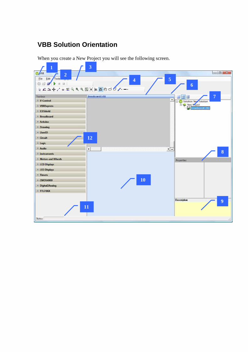
VBB Solution Orientation When you create a New Project you will see the following screen.
1 2
4 6
7
8
9
5
10
12
11
3

1. VBB Application Window 2. VBB Application Menu 3. The VBB application Toolbar 4. The current DesignSheet Toolbar 5. The current DesignSheet highlighted by blue header 6. The layout toolbar 7. The solution Explorer 8. The properties panel 9. The property description panel 10. Empty panel 11. Status Toolbar 12. Toolbox of currently select DesignSheet
VBB is context sensitive to the current DesignSheet, the toolbox and toolbar changes when the currently selected DesignSheet changes.
1. VBB Application Window The VBB Application is a MIDI ( Multiple Document Interface ) style application where the document being managed is the DesignSheet
2. VBB Application Menus
File Name ShortCut Description
New Ctrl + N
Opens the New Project Dialog with the New Tab selected. Only available when no solution is loaded.
Open Ctrl + O
Opens the New Project Dialog with the Existing Tab selected. Only available when no solution is loaded.
Close Solution
Closes the current solution and returns to the closed solution state. Only available when a solution is loaded.
Save Ctrl + S Saves the current solution Save As
Opens the Save Dialog prompting for the new project name. Only available when a solution is loaded.
Export BOM Exports the BOM Exit
Shut down VBB Only available when no solution is loaded.
BOM Export Exports a BOM ( Bill of Materials ) which is a list of the components in a Breadboard design as designated by the component ID and with a component descriptor

Clicking this menu option will open a file save dialog which can be used to name and locate the BOM text file.
For example the BOM text file for the about circuit might look
BOM.txt
?? Breadboard True False R1 1k R2 100 C1 100nF

Edit Name ShortCut Description Cut Ctrl + X Copies the current selection to the clipboard and deletes the
selection from the current DesignSheet. Only available when a DesignSheet is active and components have been selected.
Copy Ctrl + N
Copies the current selection of the current DesignSheet to the clipboard Only available when a DesignSheet is active and components have been selected.
Paste Ctrl + O
Pastes the components copied to the clipboard to the current DesignSheet. Only available when a DesignSheet is active and components have been copied to the clipboard.
Delete
Deletes the current selection from the current DesignSheet. Only available when a DesignSheet is active and components have been selected.
Help Menu Name ShortCut Description Update ICEShield Firmware
Starts the ICEShield firmware update dialog
About Opens the About dialog Update ICEShield Firmware The ICEShield firmware is updateable and the firmware to match a specific release of VBBExpress is embedded in the VBBExpress.exe To update the firmware
1) Make sure the ICEShield is connected to a USB port 2) Click the Update ICEShield Firmware menu option
An update dialog will appear showing the progress.
It take about 20 seconds to complete at which time you will get a message to indicate the firmware has been successfully updated.


About Opens the About Dialog

The VBB application Toolbar
Name Description New Opens the New Project Dialog with the New Tab selected.
Only available when no solution is loaded. Open Opens the New Project Dialog with the Existing Tab selected.
Only available when no solution is loaded. SaveAll
Saves the current solution to disk. If this is the first time saved then the Save dialog is opened. Only available when a solution is loaded
Run
Runs the emulation for the current solution. Only available when in design mode.
DesignSheet Toolbar The DesignSheet Toolbar contains tools for editing and navigating graphical DesignSheets. Like the Toolbox, the Toolbar is updated with the tools specific to the currently selected designer and updates when a new designer is selected.
Current DesignSheet The current DesignSheet TitleBar is highlighted green
1. You can always click into the TitleBar to select the DesignSheet as the
current DesignSheet 2. Some DesignSheets allow you click anywhere on the DesignSheet to select it
The layout toolbar The design panel has up to three design panes. Each pane may contain a DesignSheet.
One Panel Show the design panel as a single design pane. Any selected DesignSheet is shown in the single pane
Two Panel Splits the design panel into two separate design panes
Three Panel
Splits the design panel into three separate design panes.
2
1

When you double click a DesignSheet in the navigation tree it is selected into one of the available panes according to its default viewing position. You can override the default location by dragging and dropping the design from the navigation tree to the desired panel. When switching between layouts the previous layout remembers which DesignSheets are in which panel.
The Solution Explorer The solution Explorer contains a tree representing the DesignSheets in the solution.
The Solution Explorer is context sensitive. Right Click on a Project to add DesignSheet

Right Click on a Source Project to add a source file to a Source Code Project

The properties panel Many items, DesignSheets and Components have Properties The properties editor is populated when components are selected with DesignSheets. The properties are specific to individual components.
When you select a component the properties box is populated with the component properties.
The property description panel When a component is selected the description of the property is displayed in the property description panel
Empty panel When a panel has no DesignSheet it appears blue. You can fill the panel with a DesignSheet by dragging and dropping a design into the panel
Status Toolbar Shows status information including runtime timing and debug information
DesignSheet Toolbox Toolbox of currently select DesignSheet The toolbox contains the collections of components specific to the current designer. Components are grouped into collections
Custom Editors Drop Down Lists
Property Name Property Values
Property Description

which can be drag and dropped onto the current DesignSheet. When the current designer changes the Toolbox is updated with the components specific to the newly selected DesignSheet.

New Project Dialog The New Project form is responsible for locating and opening an existing project or project template or creating a new project. It is the first form that appears when you start RoboPAL. It also appears when you select New or Open from the Main Form. There are 4 tabs
• New • Existing • Recent • MarketPlace
.
New Tab The New Tab is used for creating New projects from project templates. A project template is a complete solution based on an example or project type which you can use to quickly get started. The templates are organized into a tree of project types to help you locate a template that best suits your embedded application challenge. The Project Types Tree on the left hand side selects the project type and the Project Templates lists the available templates for the selected type.

The Project Types Tree is a collection of project templates.
Click the folders to show the list of templates
The Project Templates are listed in the Project Template list.
Double-Click the template to open it

Follow the hierarchy to locate the examples
Double click on the example to open the example

Existing Tab The Existing Tab allow projects that already exist to be located and opened
1. Existing Tab 2. List of VBB Solutions in the current directory 3. Drop down navigator 4. Move up to the previous directory
The navigation dropdown list allows you to search the computer for directories containing an existing VBB solution to open
2
3 4
1

Recent The recent tab hold the most recently used project list for quick access to recently used projects.

Market Place The MarketPlace Tab shows a list of products and current activation status. You can purchase products directly from the MarketPLace by clicking the BUY NOW button of the feature your interested in. As more features are added they will appear in the marketplace
Activating a VBB Feature When you buy a VBB Feature using PayPAL the PayPAL receipt contains an invoice number. This invoice number is the activation code for the purchased feature.
Here is a sample receipt, the invoice number is highlighted in red.

Activating a feature To activate a feature you have purchased in VBB you first start VBB and locate the MarketPlace tab. Then you copy the invoice number from the PayPal receipt into the Activation TextBox and click the Activate button. The activation code will be checked online and when valid the feature will become ticked with a green box to indicate its activated and ready to use.

Activating multiple features To activate more than one feature enter each activation code seperated by a comma ',' and press the Activate button.

Shipping
• The V18'O and ICEShield and other physical products are fullfilled from the Netherlands. • Standard shipping is included in the price. There is no tracking number available.
o Shipping time Europe : 2 to 5 days o Shipping time non-EU : 5 to 15 business days
Order Processing
• Sales made to european customers are processed by our Australian subsidery. • Sales made to non-european customers are processed by our European subsidery.

Design Sheets Context Sensitive Elements When a DesignSheet is activated the Toolbar and Toolbox change to the match selected DesignSheet
• Sheet Area • Toolbar • Toolbox
Standard Edition DesignSheets DesignSheets are the main document managed by the VBB system. The standard design sheets are part of the standard version of VBB. Addition DesignSheets may be available with VBB Extended Features are enabled.
Java Source Code Projects ( *.SRC )
The source code project is a special type of DesignSheet which contains a collection of java source code files for creating Java based applications.
Breadboard ( *.VBB)
The Breadboard is a DesignSheet supporting the OpenVBB emulation framework. Components designed using OpenVBB can be dropped into a Breadboard DesignSheet, wired up and simulated
Logic Analyser ( *.VLI )
Virtual MulitChannel Logic Analyser Instrument that is very useful for analyser logic signals for debugging and testing
Trace Log ( *.VLG )
Virtual MulitChannel Logic Log logs signal changes and enables view filtering to interpret the log for debugging logic circuits.
Feature Extension DesignSheets VBB is designed to be extended with additional pay-for-feature extensions. Some feature extensions will add new design sheets. For example the Arduino Toolkit adds the Arduino Code Generators. These extension design sheets will be documented in the user manual for the specific extension.
Arduino ( *.ARD) ( Arduino Toolkit ) Arduino code generator interfaces with the Arduino code chain and programs the device inline. Contains configuration information including the location of the Arduino toolchain, COM port to connect with target device.
Java Source Code Project Design Sheet

The Java Source Code Project Design Sheet is a design sheet that contains a java project manager which manages a collection of java source code and java editor for editing the source code.
• Properties • Sheet Area • Toolbar • Toolbox
Solution Tree Manager In the project manager view the Java Source Code Project appears with the list of the source files it contains as a sub-tree member
Activating Java Source Project You can select the Java Source Project as the currently selected design sheet by clicking the title banner ( the normal blue title bar is hidden) or double clicking the Java Source Project in the solution tree. Some functions such as copy/paste wont work as expected if the currently selected design sheet is not the Java Source Project containing the source editor you are working with.
Context Sensitive Functions By right clicking on a named Java Source Code Project in the Solution Tree the context sensitive functions are shown

Add New Java Source File The Add New Java Source File menu allows you to add new source files to the project and pops up a dialog to allow you to name or select the java source file to add.
1 Suggested Source File name When the Add New java Source File dialog appears it has a suggested Classname. To add you a new file you can accept this name or rename it to your preferred name. The name must be unique to the source code project which means there must not be another file of the same name in the solution directory 2. Solution Files The java source files for the solution directory are shown in the Solution Files list. It can be that the source file is in the directory , for example if you have copied it directly into the directory, but not yet included in the project. In this case you can select the name from the solution files list and click OK to include it 3. Import You might have source files you want to include in other directories. In this case you can click the import button to open a file dialog to allow you to select a file to import into the solution directory. Once imported the file will appear in the Solution Files list where you can select it to include it in the project as per (2)
1
2
3
4

4 Once you have named a new file or selected an existing one click the OK button to add it to the source project. If the file name you have selected is not unique you will receive the ‘File Already in Project’ message and the source file will not be added.
Delete You can delete a java source file by right clicking on it in the Solution tree and clicking the delete menu option The Java Source file will be removed from the Solution and also deleted from the solution directory
Rename You can rename delete a java source file by right clicking on it in the Solution tree and clicking the rename menu option
The in-tree editor will then become enabled where you can edit the new name of the file
When you click enter the name of the Tab source class name is also renamed but the class Name in source is not renamed so you need to manual rename the source name. The name of the source name and the class name should match up

Properties Double click the Java Source Project in the Solution Tree to select the properties into the Properties Box. Property Description Code Generator The Code generator property is used to link the Java Source Code files
to optional Code Generators such as the Arduino Code Generator when the Arduino Toolkit is activated. The default Code Generator is the Muvium Code Generator with Frappuccino framework
Development Mode There are two development modes. Emulate Emulate+Debug In Emulate mode the code dynamically compiled using the Microsoft J# provider and executed as a Microsoft .DLL. This is faster execution speed but cannot be debugged In Emulate+Debug the code is compiled to java classfiles and executed on a custom JVM which models the muvium runtime. This is debuggable but executes slower.
ClassPath The ClassPath allows additional external libraries to be included in the project. The classpath must point to source file directories and be absolute directory path values separate by semi colon.
Working with ClassPath The ClassPath to java is similar to the include path to C. VBB has only limited support for ClassPath and is restricted to Java Source Paths at the moment. This means for example Java Jar files cannot be used in the ClassPath yet. The reason is the j# code provider used in the emulate mode cannot process java class files. You use the ClassPath to include libraries you use regularly and want to share between projects. In order for a library to be able to be included in a VBB project it must use a package name and the directory path pointed to by the classpath must point at the top of the package tree.

Say for example you have a library file called MyUtils.java in order to be able to include this in your java App you must 1 Use a Package Name The package name appears as the first line of any Java class. Give a package name, for example myLibs, your java code would like follows
The full name of the class includes the package. Here its myLibs.MyUtils. By java convention java packages start with lower case and java class files start with upper case characters 2 Save in the Package Name hierarchy with respect the ClassPath So for say you Library directory you use in your ClassPath is “c:\Users\James\Library\;”
Then you need to save your MyUtils.java file in the MyLibs directory
First line is package name
Class is in the package. FullName is

So the hierarchy looks like this “c:\Users\James\Library\;” < ClassPath Directory “c:\Users\James\Library\myLibs\ << Package Directory “c:\Users\James\Library\myLibs\MyUtils << Library Source Code You can also use ‘.’ Separated names for package names for example package myLibs.math ; In this case the directory structure extends with ‘.’ Becoming sub directories “c:\Users\James\Library\;” < ClassPath Directory “c:\Users\James\Library\myLibs\math << Package Directory “c:\Users\James\Library\myLibs\math\MyUtils << Library Source Code
3. Use the Import with Package name in your Application To actually enable the Java Source Code Project to find your library you need to include it using the import statement.
Working with Packages within the Java Source Project Normally you create a sub directory heirachy to reflect the java package path. This is not presently supported in Source Projects. However you can work with the flat hierarchy. So for example to add a myLibs.MyUtils java class file you just add the package name to the java class file.
use the import with the package+ClassName

Then import and use it
However, if you then want to share MyUtils as a library you must copy the file into the package name sub directory structure for it to be locateable

Sheet Area The Sheet Area contains the editors and information tabs. There are two possible configurations
• Design Time Configuration • Runtime Debug Configuration
Design Time Configuration
Debug Runtime Configuration
1
2
3
4
5

1. Source Code Tabs – Click the tab to select the source file as the current file 2. Design Time Source Editor – Editor the for the current source file with design
time features tab completion etc 3. Design Information Tabs – Errors, Output, Classes Allocation 4. Runtime Editor with runtime features such as current line, call trace, breakpoint 5. Runtime debug Tabs = DebugXmlDoc, Local Variable, CallStack
Design Time Source Editor The Editor at Design Time has useful features typical of modern source editor
Keyword Highlighting The editor understands the code is a java and highlights the java keywords such as import, public, class , extends etc. This make the code more readable
Syntax Error Highlighting The editor can also detect when a syntax error has occurred with the java language structure and will highlight the syntax error with a red squiggle underscore to assist in locating and correcting the syntax error.

Tab Suggestions As you type can get completion suggestions by typing {CTRL}+{TAB} This will popup a context sensitive context box based on you’re the text entered so far.
You can navigate the suggestions box using the mouse or the {UP} and {DOWN} arrow keys Pressing {TAB} or {ENTER} will choose the selected suggestion and enter the text. This is useful for getting the exact syntax of a function based on its partial name
Parameter Suggestions When you have entered a recognised function name when you type the ‘(‘ you will receive parameter suggestions to help complete the function
Toggle Breakpoints Clicking in the left hand margin toggles breakpoints on and off for a particular line of code. Breakpoints are used to stop execution when in Emulation+Debug mode

Edit Menu, Cut, Copy and Paste Undo You can cut, copy and paste code sections in the Source Editor.
TIP: If the Java Source Editor Project is not the currently selected design sheet the Cut/Copy/Paste functions wont work with the Source Editor. See Activate Java Source Project
Design Time Tabs
Errors Tab

The errors tab contains a list of any syntax errors generated at build time. When you build the project the source code is compiled into java bytecode first by java J# code provider as a quick check and then secondly by the java jikes compiler. If errors for either of these two java compilers are generated then they are listed in the Errors tab. For example if you mistyped util as uti ls then the compiler would locate the error. If you Click on the error in the Errors tab then the error line will be located and highlighted in yellow
Output Tab At design time the OutputTab reports design time information such as muvium compiler output
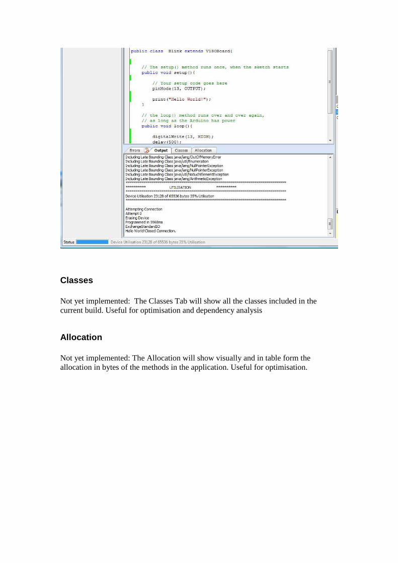
Classes Not yet implemented: The Classes Tab will show all the classes included in the current build. Useful for optimisation and dependency analysis
Allocation Not yet implemented: The Allocation will show visually and in table form the allocation in bytes of the methods in the application. Useful for optimisation.

Runtime Tabs
Output During runtime the Output tab shows the output of the standard output from the emulated code
.
DebugXmlDoc

In Emulate+Debug mode when a breakpoint is hit or a single step executed a snapshot of the JVM memory is made and published as a Xml document. To interpret the document you need to know a few things about a JVM
Heap Heap = { References } The Heap is a collection references where a reference is Object or an Array. Each object has an object Id which is used to reference other Objects. The Heap is Garbage Collectable so when an object is not longer referenced it becomes available for collection the next time the Garbage collector runs. The GC runs when there is not enough memory to create a new instance of an object or when a user invokes System.gc
Reference Reference = Object | Array
Object Object = { Fields} An object is a collection of Fields.
Array An array is a collection Reference of DataType Array = { Reference | DataType }
DataType DataType ShortCut Min Value Max Value boolean True | False byte Signed 8-bit byte char Unsigned bit short Signed 16-bit int Signed 16-bit Long Signed 32-bit Float 32-bit modified IEEE Double 32-bit modified IEEE

Field A Field is a store for data type or a reference Field = Data Type | Reference
Thread Thread = { FRAME } A Thread is an independent execution context consisting of a collection of execution frames. Threads switch execution using the Thread.yield() or Thread.sleep() method.
Threads Threads = { Thread } Threads is a collection of Thread
FRAME A frame is a execution context of a Method consisting of Local Variables and a Operand Stack.
Method A method is a collection of java bytecode that is the output of the java compilation processes. A method executes the java bytecode using the frame location variables and operand stack to hold the partial results of the execution.
Local Variables Local Variable = DataType | Reference Are fast access registers in the frame execution context, including the method parameters, that contain either a datatype or a reference.
Frame Operand Stack Frame Operand Stack = { DataType | Reference } The frame operand stack is a stack of DataType or reference that hold the partial results of the stack based operations of the Java Virtual Machine.

Interpreting the XML SnapShot View When the JVM hits a breakpoint a snapshot of this memory model is made. This Xml view allows a complete snapshot of the memory model of the JVM. It is human readable view but it is a raw view which other views such as the local variable or call-stack view construct their views. In the example shown <DEBUG> <HEAP> <OBJECT id="0" type="Blink"> <int name="count">4</int> <array name="bytes" type="byte[]">#1</array> </OBJECT> <ARRAY id="1" type="byte[]" length="2"> <byte index="0">72</byte> <byte index="1">105</byte> </ARRAY> </HEAP> <THREADS> <THREAD> <FRAME class="Blink" method="methodCall" signature="(I)V" sourcePC="31"> <int name="localA">3</int> <object name="this" type="LBlink;">#0</object> <int name="param">3</int> </FRAME> <FRAME class="Blink" method="loop" signature="()V" sourcePC="50"> <object name="this" type="LBlink;">#0</object> </FRAME> </THREAD> </THREADS> </DEBUG> <DEBUG> Lets Look at this snapshot one section at a time. XML is collapsible and
DEBUG = { HEAP, THREADS }
So DEBUG (Doc) contains 2 main block, the HEAP and the THREADS representing the memory model of the JVM
HEAP
HEAP = { Blink, byte[] }

The HEAP is a collection of references, there are 2 references an instance of OBJECT Blink and Array of type byte with length of 2.
Blink = { count, byte[] }
The first Reference in the HEAP is an Object with id=0. Is an instance of user defined type Blink and contains a collection of 2 fields, an integer named count with value of 4 and reference to the byte array stored on the heap with reference id 1.
The second Reference is an ARRAY with Reference id =1 so this is the reference that the Blink.bytes filed is referenceing. It is a byte array of length 2 with 2 values, { 72, 105 } = { ‘H’,’i’ } .
Threads
Threads contains a single Thread so this application is single threaded. The single thread contains two frames which constitute a FRAMESTACK The currently executing FRAME is for the method methodCall from the class Blink. It was called from previous call in the framestack which is from the method loop.
The methodCall frame has 3 local variables which correspond to the source code for the methodCall method.

However looking at the source code it seems to have only 1 local variable, localA. The java compiler though includes parameters as local variables so param becomes a local variable. In addition for methods that are not static, java creates an additional local variable to save the class instance that the method is called from. This is the ‘this’ variable and is accessed in code using the this keyword. You can also see the current values of the local variables, localA and param have value 3 and ‘this’ is a reference which points to heap id=’0’ which we say earlier as the first object in the HEAP. When count++ is executed this operates on the instance of the class in ‘this’, so the field count will increment and now has the value 4 which means methodCall has been called 4 times up to this breakpoint.
Local Variable Tab The local variable tab is a view of the current frame of the DebugDocXml. Using the same data from the previous example the Local Variable Tab will construct a navigateable tree view with some additional markup to help focus on the specific information you are interested in. Here we can see the same 3 variables, localA, param and this along with their Type and values in a more direct view.
The object ‘this’ is a collection of fields and we inspect the fields by clicking ‘+’ to open the field collection in the view. Now we can see the instance ‘this’ contains the field count with value 4 and the references bytes. A summary of the contents of the byte array is shown in the Value field but you can inspect the specific members by clicking the ‘+’

So in this way you can navigate the data model of the memory snapshot

Call Stack The Call Stack is also a view of a specific part of part of the DebugXmlDoc, specifically the FRAMESTACK of the currently executing Thread.
The Call Stack has the additional feature of allowing you to select the current frame to view in the Local Variable View. So if you clock the Blink.loop() in the Call Stack the currently selected Call with be highlighted with a green arrow line. The source line for where the call was made will (todo) be highlighted as a green source line and the frame viewed by the Local Variable tab will change to that selected by the Call Stack
Clicking the topmost member of the call stack element highlights the line with a yellow arrow and line to indicate this is the currently executing line.
Toolbar : Java Source Code Project

The Source Code Project toolbar
Emulation Mode
There are two emulations modes supported. Emulate Emulate+Debug
Emulate mode The java source code is compiled into a Microsoft .DLL by the J# Code Provider. The dynamic .DLL is loaded and the code is executed at full speed on the microsoft .net runtime. This is the full speed emulation mode but doesn’t support debugging.
Emulate+Debug mode The java source is compile into java byte code by the jikes compiler. The java byte code is loaded into custom JVM which executes the code and supports debugging. This mode is potentially slower execution but supports debugging. In Emulate+Debug mode the debug toolbar becomes active when the virtualbreadbaord circuit is executed and the device is started in suspend mode. This allows you to set any breakpoints and gives you the option to either step or run the App. However, this is a source of potential confusion when compared to Emulate only mode when you just want to run the emulation because you need to press run twice. First press run the circuit and second press run to start the emulated App.
Icon ShortCut Description
Build Builds the Java Source Code Project Application. The Java source code is pre-processed by the Microsoft J# Code Provider before being compiled by the jikes java compiler. Errors for either compilation are shown in the errors tab.
Reset During executing in Emulation+Debug Mode resets the PC to 0 and halts the emulated micro returning it to the state it had when the circuit was first started.
Step Clock Future
Run Emulation Runs the emulated Micro App. Will run until the code hits a

breakpoint or the user clicks pause.
Pause Emulation
Pause the Debug Micro emulation. Will enter step mode, the current line will be highlighted yellow and the debug views will be updated with the current snapshot of the memory model
Step Steps the current source line. The debug views will update and the current line will be highlighted
Step Out Future
Step Over Future
Remove All Breakpoints
Removes all the Breakpoints
Emulation Mode
One-Click Program
Builds and programs a real-micro target. Will call build if the source code has changed and will call the Code Generator attached to the current java source code project. The default Code Generator is the Muvium Code Generator for Frappuccino. When programming the status is shown in the bottom left status bar

Breadboard DesignSheet The Breadboard DesignSheet is a circuit emulation enabled drag and drop design sheet.
• DesignSheet – the DesignSheet a design graphic containing the component models
• Toolbar – the Breadboard toolbar is populated with graphical manipulation tools to zoom pan and manipulate the graphical design
• Toolbox – The Breadboard toolbox is populated with electronic component models which can be dragged and dropped on to Breadboard design
Toolbar : Breadboard The graphics toolbar allows the manipulation of the Breadboard graphics, components and links.
Toolbar Button Description Run Emulation Starts an Emulation of the virtual circuit - requires an
ICEShield Stop Emulation Stop the Emulation and returns to Design mode.
Select Mode Enters Select Mode. The cursor becomes an arrow. In select mode click on components to select them. Selecting a component populates the property box with the component properties.
Rotate Left Rotate Left. Rotates a component 90 degrees left.
Rotate Right Rotate Right. Rotates a component 90 degrees right.
Move Mode Enters move Mode. The cursor becomes a NSEW pointer. In move mode you can drag and drop component to new location .
Link Mode Enters link Mode. The cursor becomes a cross-hair and you can draw links between component pins.
Junction Merges two links by joining with a junction.
Net Merges links with the same net name
Zoom Zoom Mode. Click the Zoom button to enter zoom mode. When over the Breadboard layout the cursor will change into a Zoom graphic. Click and hold the mouse down and then moving vertically up will zoom out and vertically down will zoom in. Stays in zoom mode until another graphic mode is selected
Zoom In Zoom in by factor 2

Zoom out Zoom out by factor ½
Zoom region Zoom to a region. Not functional @v0.1
Zoom Extents Zoom to the extents. Not functional @v0.1
Restore Origin Restore the origin to offset 0,0 and zoom =1
Lock origin Lock the origin when zooming. When locked the offsets don’t change only the zoom factor. When not locked the offset changes to keep the center of the screen fixed
Pan Pan Mode. Click the Pan button to enter Pan mode. When over the Breadboard layout the cursor will change into a Hand Zoom graphic. Click and hold the mouse down and then drag the display to pan around. Stays in Pan mode until another graphic mode is selected
Grow Grow the selected components by factor 2
Shrink Shrink the selected components by factor ½
Link Color Set the link color. Sets the currently selected links to the selected color. Future links will be created with the new color.
Link Weight Set the link width. Sets the currently selected links to the selected weight. Future links will be created with the new weight.
Show Nets Show the virtual nets between named nets in the circuit board.
Note on Zoom factor: The snap to grid has a problem when the zoom factor is not a multiple of 2. You should not try to select links or draw links at arbitary zoom factors. The zoom, zoom extents, zoom region are best used to inspect the design and select components but you should restore the origin and use the zoom in, zoom out when drawing links to ensure the zoom is a multiple of 2.

DesignSheet : Breadboard
Placing a component from the Toolbox Placing a component is an important skill – not quite drag and drop. You need to click on the Toolbox icon releasing the mouse button. This attaches the component to the mouse pointer when you move over the Breadboard design. You can then drag the component into position in the DesignSheet and click a second time to place the component.
Component Editing There are several ways you can work with components.
• Placing a component • Select a component • Select a group of components • Append a component to a selection • Move a group of selected components • Copy and paste selected components • Delete selected components

Placing a component from the Toolbox Placing a component is an important skill – not quite drag and drop. You need to click on the Toolbox icon releasing the mouse button. This attaches the component to the mouse pointer when you move over the DesignSheet. You can then drag the component into position in the DesignSheet and click a second time to place the component.
Select a component
To select a component enter Select Mode and left click on the component Selected components are bounded by a dashed blue line.
Select a group of components Select a group by drawing a window around the components to select. Draw a window with a Left Click to anchor the window, and holding down the mouse button drag out a window. Release the mouse to select the components fully inside the window.
Append a component to a selection
Left Click-and-hold to drag out window
Selects components fully inside window
Selection Box

Append a component to a selection by holding shift and left clicking the component.
Move a group of selected components To move a selected group of components
Select Move Mode by clicking the move state button Shift + Left Button drag and drop or Right button drag and drop.
Shrink and grow a selection To increase density of certain parts of a graphical design it can be useful to scale down a component or group of components. Equally it is useful to be able to restore the size of the components and scale components back up.
Shift + Left Click
Shift + Left Click-and-hold OR Right Click-and-hold
Drag to reposition Release to place. Selection remains

To scale down a component selection
• Click the scale down component toolbar button
To scale up a component selection
• Click the scale up component toolbar button

Wiring Essentials Wires are links from component pin to component pin.
To begin wiring click the wiring button The cursor will become a crosshair
To start a link move to the pin to create a link from and click the left button
The link will attach to the pin and to the mouse cursor. Move the cursor to the first joint of the link and press the left button again

Now the link is anchored to the last joint and the cursor Click again with the left mouse on the next joint location or the destination pin or Double Click to finish the pin
Now the link is anchored to the destination pin and the cursor To finish the link right mouse button or double click
When a link is made between two pins the link becomes thicker to indicate the link is an active link

Working with Junctions Junctions are used to merge links together. Note: Links overlayed over each other are not considered a single link To create a junction click the junction mode and then
Links need to be merged with a junction to become active
Links touching or crossing are not merged together without a junction Enter Junction Mode and click with the left mouse to place junctoins

Working with Net Labels Net Labels allow connections to be made between pins by using a name instead of a wire. This can be used to better organise the connection layout. The Net Toolbar option is used to place nets and features some helper options to add nets
New New is the standard option to add a new net. When you add a new net it is placed with the Name new. You can edit the name by clicking the net name and editing the name in the property box
Drop Down List of Named nets You can also select a net from the drop-down list in the property box. The dropdown list contains the names of all the nets currently on the Breadboard.
AutoInc

The AutoInc dropdown option has a further sub dropdown menu which allows you to select a net using the common prefixes ( R = Resistor, C = Capacitor, L = Inductor , U = Integrated Circuit ) When you select form the submenu the net will be named +1 to the current highest net name. So for example if you have R1,R2,R2 on your breadboard already and you select R* then the net will be named R3.
DX / AX The V18’O, Arduino and others have a naming convention for digitial pins of D0, D1, D2 .. and Analog Pin A0,A1,.. These nets are also automatically added when using the V18’O, Arduino components so these are very commonly used net names. The AX and DX submenus gives you a shortcut for selecting these names.

All Nets (--) All the current nets on the Breadboard are listed below the – toolbar separator giving a shortcut to select a matching net for a net to be placed.
Virtual Links Nets can be thought of as acting a virtual link between the pins that are connected by the Net Nets can be
• Connected to the end of links or midway along links like junctions • Placed over pins directly

Show Links You can view the links between the nets using the ShowLinks button. When you click the button it will show the links. It is a state button and when you unselect the button it will hide the links again.
Showing specific Net Links To show a specific net link you can select a member of the net and click to ShowLinks button
Show subgroups of links If you select members of more than one net then the links belonging to all the selected nets will be shown.

Predefined Nets Arduino footprint boards have predefined nets associated with the pins
By default the nets for these on but you can switch off the default nets using the components Nets property
Component Layering

Components are layered , you move components up and down the layering using the context menu. Select the component and press right click to start the context menu.
Locking a Component
The context menu contains an option for locking components. Select the component, right click to bring up the context menu and click Lock Control to lock the component. A locked component cannot be accidentally moved.

Toolbox : Breadboard The Breadboard Toolbox is the most important Toolbox to VBB as it contains the component models that constitute the circuits
• VBBExpress • ICEShield • Breadboard • Arduino • Drawing • UserIO • Circuit • Logic • Audio • Instruments • Motors and Wheels • LCD Displays • LED Displays • Timers • CMOS4000 • Digitial2Analog • TTL74XX


VBBExpress
The VBBExpress group are make-able Breadboards which when used in your designs can be converted into Printed Circuit boards by our low cost PCBExpress service. The Breadboards available in VBBExpress group while being representative of typical solderless Breadboards they are unique designs that can be converted into a real PCB using the VirtualBreadboard PCB service. In particular you should notice the power rail configuration. In a regular solderless Breadboard there is no required orientation of VDD/GND but with the Makeable VBB Breadboards the RED edge should be used for VDD and green edge as GND.
VBB 30 x 1 The 30 x 1 is a 30 Column x 1 Row VirtualBreadboard ideal for small circuits and interface circuits to microcontrollers like the Arduino.
Properties Property Description ID Identifier used in BOM PCB Overlay The Overlay to use when fabricating a VirtualBreadboard. Breadboard
| Bitmap | { Color }
VDD
30 Column
GND
VDD
GND
2 Row

Breadboard – Shows the same Breadboard pattern as used in design time Bitmap – Use the Bitmap in the Overlay Bitmap as the Bitmap Color – Use the selected color as the color for the whole background
Overlay Bitmap The Bitmap to use for the Overlay when the PCB Overlay property is set to Bitmap. The bitmap is selected using the popup file dialog The bitmap is stretched to fill the PCB. The suggested size is ( 420 x 320 ) PNG bitmap
Show PCB Links When true the wire links are shown in the overlay. When false the wire links are hidden in the overlay
See Menus => File => PCB Preview

ICEShield
ICEShield
The ICEShield is an Arduino form factor “Shield”. When you attach an ICEShield to an Arduino or other Arduino form-factor microcontroller such as a V18’O or Netduino, Uno32, Amicus or so on, the ICEShield does one of two things depending which way you look at it. From the Microcontrollers perspective, the ICEShield looks like the Breadboard electronic circuit designed in VBBExpress. A ‘Virtual Circuit. From the Virtual Circuits perspective, the ICEShield looks like the Microcontroller attached to it. A Virtual ‘Arduino’, ‘V18’O’, ‘Netduino’ etc. Property Description ID Identifier used in BOM Virtualised The Avatar of the ICEShield graphic
ICEShield | ArduinoUNO | V18’O | Netduino | Amicus | Uno32
Wait Pin The pin to assign the Wait pulse. The Wait Pin can be used by the Microcontroller to ensure its output pins have been read. *
Synch Request Pin The request pin can be set high by the microcontroller to request a signal synchronisation.*
Synch Ready Pin The ICEShield sets the Synch Ready Pin high when a synchronisation with the virtual circuit is complete. *
* See the ICEShield User Manual for more information
Avatars

ICEShield
This is the default Avatar and is a visual representation of the ICEShield itself
V18’O
V18’O is VirtualBreadboards own Java based Microcontroller www.virtualbreadboard.com www.muvium.com
Uno
Uno is the popular Arduino Uno footprint www.arduino.cc
Uno32
Uno32 is the Microchip PIC32 ChipKit board http://www.chipkit.org
Netduino
Netduino is the popular Microsoft .NET board www.netduino.com

Amicus
Amicus is a pBasic powered microchip board http://www.myamicus.co.uk/
ICEShield Aware Drivers
When a real microcontroller connects to a virtual component model through the ICEShield there is a delay introduced by the ICEShield. Microcontroller libraries that drive both real and virtual components like the LiquidCrystal display must be made ‘ICEShield aware’ and introduce the appropriate ‘Wait States’ in their implementation. This is best done as a conditional compile statements in the timing sensitive parts of the routines. This is typically only a few additional lines of code which are compiled out when working with a real version of the hardware. As an example the LiquidCrystal component model has a timing sensitive section when sending the pulse enable. Conditional compile commands VBBWait() are added to edges of the pulse to ensure the edges are captured. void VBBLiquidCrystal::pulseEnable(void) { // delayMicroseconds(2000); VBBWait(); digitalWrite(_enable_pin, LOW); delayMicroseconds(1); VBBWait(); digitalWrite(_enable_pin, HIGH); delayMicroseconds(1); // enable pulse must be >450ns VBBWait(); digitalWrite(_enable_pin, LOW); delayMicroseconds(100); // commands need > 37us to settle VBBWait(); }
You should refer to the ICEShield user manual for more information on the ways to work with the Wait and Synch pins to created ICEShield aware drivers.
ICEShield Aware SDK’s ICEShield aware SDKS are collections of Drivers that are ICEShield aware.
Frappuccino

Frappuccino is the Java Arduino compatible port sponsored by VirtualBreadboard and Muvium. www.muvium.com The Frappuccino SDK is the ‘native’ VirtualBreadboard SDK which is the reference implementation. All VBB/VBBExpress Component Models will always ship with a Frappuccino SDK driver.
ArduinoSDK ICEShield ‘aware’ libraries for the Arduino
Uno32 SDK ICEShield ‘aware’ libraries for the ChipKit Uno32
Hybrid Emulation Circuits Another possibility with ICEShield when the optional ‘Stack-able’ headers are installed is to create Hybrid circuits. A Hybrid circuit is where you use real components alongside virtual components.
Updating the ICEShield Firmware See Menus => Help => Update ICEShield Firmware
Breadboard Components There are two types of Components in Breadboard
• Generic Layout ( No Emulation ) • Component Models ( Emulation )
These can used used in combination on circuit but only the sections of the circuit that contain Component Models will emulate.
Layout Components

Layout Components are generic graphics only components and will not emulate. These components are parametric models of the common hole-through components. Layout components help you create a circuit board which can be fabricated by our PCB service or as a guide when assembling a real circuit board even where specific components models are not available.
Generic Layout Only • Generic DIP • Axial • Radial
Generic DIP
Breadboards are useful because they have pin sockets that match the spacing of the standard DIP packaging of electronic circuits. The Generic DIP component allows you to easily create a DIP component package.
DIPs components are typically placed across the center section.

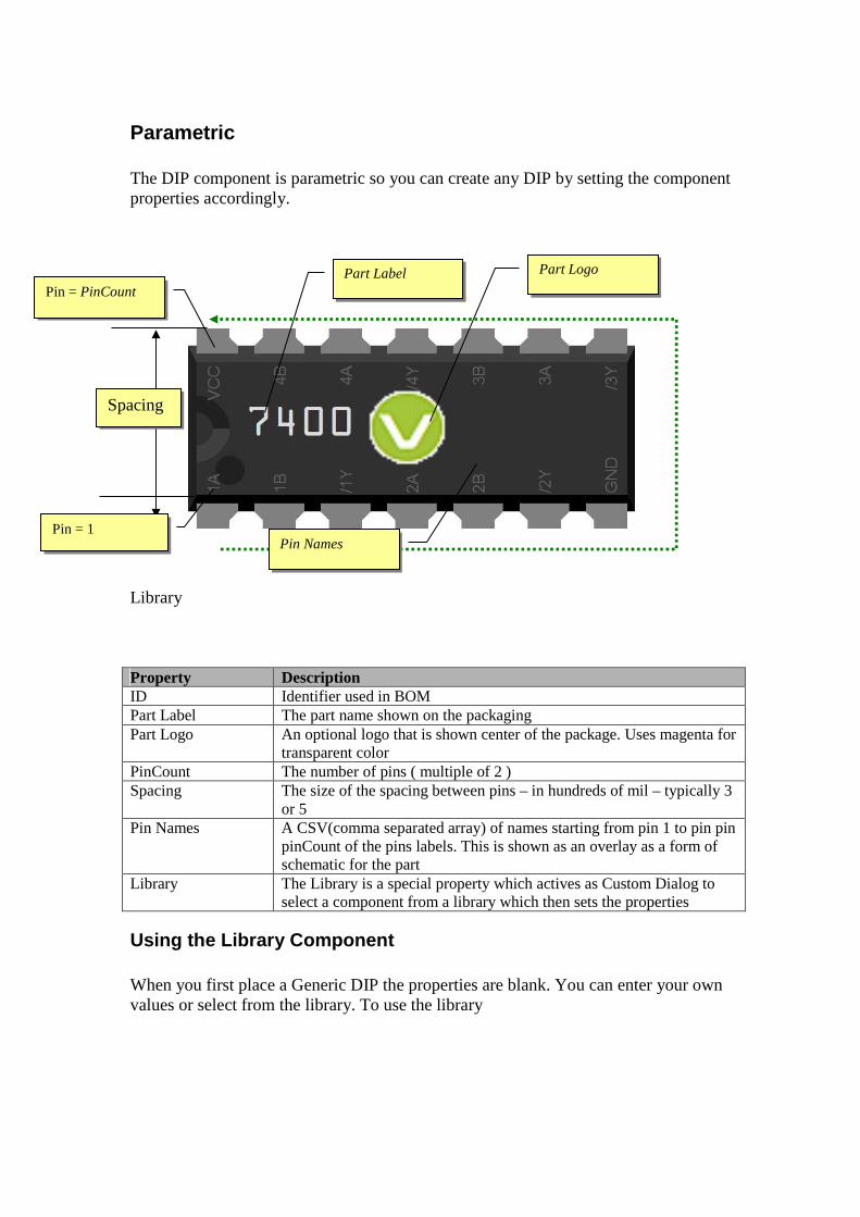
Parametric The DIP component is parametric so you can create any DIP by setting the component properties accordingly. Library Property Description ID Identifier used in BOM Part Label The part name shown on the packaging Part Logo An optional logo that is shown center of the package. Uses magenta for
transparent color PinCount The number of pins ( multiple of 2 ) Spacing The size of the spacing between pins – in hundreds of mil – typically 3
or 5 Pin Names A CSV(comma separated array) of names starting from pin 1 to pin pin
pinCount of the pins labels. This is shown as an overlay as a form of schematic for the part
Library The Library is a special property which actives as Custom Dialog to select a component from a library which then sets the properties
Using the Library Component When you first place a Generic DIP the properties are blank. You can enter your own values or select from the library. To use the library
Spacing
Pin = 1
Pin = PinCount
Part Logo
Pin Names
Part Label
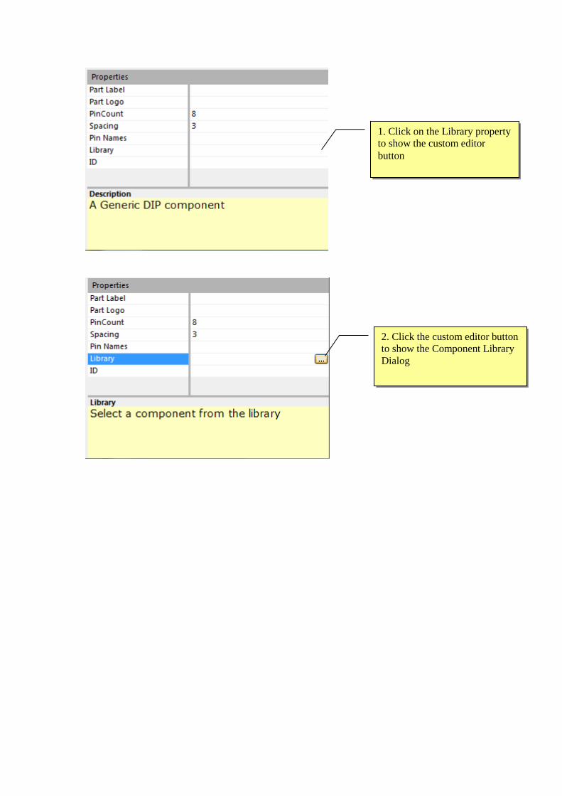
1. Click on the Library property to show the custom editor button
2. Click the custom editor button to show the Component Library Dialog

This sets the properties for the component creating the component.
3. Click the component group 4. Select the component
5. Click OK

Radial Component Generic Radial component can be used to model components with a 2 pin Radial configuration for which there is no matching visual component.
Parametric Model
Properties Property Description ID Identifier used in BOM Spacing The number of grid spacings between pins Diameter The diameter of the radial component in grid spacings (0.1”) Color The color of the Radial packaging Value The value of the part to appear in the BOM.
Eg Capacitance or special part no.
Diameter
Pin 1
Pin Spacing
Color

Axial Component Generic Axial component can be used to model components with a 2 pin Axial configuration for which there is no matching visual component.
Parametric Model
Properties Property Description ID Identifier used in BOM Spacing The number of grid spacings between pins Diameter The diameter of the axial component in grid spacings (0.1”) Length The length of the axial component in grid spacings (0.1”) Color The color of the Radial packaging Value The value of the part to appear in the BOM.
Eg Capacitance or special part no.
Diameter Pin 1
Pin Spacing
Color
Length

Component Models The second type of VBBExpress components are Component Models. Component Models are realistic representations of common components used in Breadboards. Components models will also emulate for many circuit configurations so can be used to validate a circuit before committing to fabrication by our PCB service and also for experimenting with different designs.
Circuit Emulation Its quite Natural to expect that VBB can work exactly like the real world. Unfortunately, as with all software VBB is just an approximation of the real world. You will also be disappointed if you expect VBB to work like SPICE and compute Voltage/Current transient behaviour of discrete components. In fact VBB doesnt calculate current at all. Nevertheless you can still approximate many of the most common circuit configurations using VBB.
Discrete Emulation Despite their limitations discretes can be used to model a wide variety of common circuit. When the circuit function is supported you can use the discrete component for both the circuit documentation and layout and the emulation. Resistors are modelled either as a straight-through wire or a pull-up or pull-down. Capacitors are modelled as an open-circuit. Diodes are modelled as switched pull-up or switched pull-down resistor. NPN Transistors are modelled as a switch which turns on when the base voltage is HIGH PNP Transistors are modelled as a switch which turns on when the base voltage is LOW
Component Models
Breadboard
ICEShield
LiquidCrystal
Resistor
Diode

LED
Momentary
Ceramic Capacitor
Tantalum Capacitor
Electrolytic Capacitor
Toggle Toggle switch
NPN Models of TO-92 NPN Transistor
PNP Models of TO-92 PNP Transistor
VREG Model of TO-220 Voltage regulator
Trimmer Model of Trimmer Potentiometer
Relay Model of a common relay
Solonoid Model of a Solonoid component
PNP Models of TO-92 PNP Transistor
7 Seg Array Module LED Matrix Module
LED Matrix Module LED Matrix Module

Liquid Crystal
Properties Property Description ID Identifier used in BOM Display Cols The number of columns of text the display will show can be used to
model different displays 8 | 10 | 16 | 20 | 32 | 40
Pins Property Description E Enable RS Register Select Pin R/W Read/Write Pin – Not functional D0-7 Data Pins. Only 4 bit mode using D4-D7 is used
Emulation
Supports HD44780 emulation in 4-bit mode.. Fonts: If available the HD44780 font is used else the default is used. Limitations
• 4 Bit mode only supported • Custom Bitmaps not supported • R/W read not support

Drivers The HD44780 clocks in data using a pulse to the Enable pin. Microcontroller software should ensure the Enable pulse is captured by co-ordinating with the ICEShield Wait() pin. The following conditional compile LiquidCrystal libraries have been made ‘ICEShield’ aware for use with the Virtual LiquidCrystal. Refer to the SDK for examples using the library. SDK Library Frappuccino muvium.processing.arduino.LiquidCrystal ArduinoSDK VBBLiquidCrystal Uno32SDK VBBLiquidCrystal

Resistor Generic resistor component models the standard axial resistor with parametric spacing and resistance color bands.
Parametric Model
Properties Property Description ID Identifier used in BOM Resistance The resistance of resistor – the color markings update according to
resistance Spacing The number of grid spacings between pins Function Emulation Mode Normal | Pullup | PullDown | document
Resistors Resistors have three modes which can be selected from the Function property of the resistor.
• Pullup • Pulldown • Normal (default) • document
Pin Spacing
Markings Bands change according to Resistance

Pullup Mode A Pullup resistor pulls a voltage HIGH if its not driven LOW.
One end of the pull-up resistor is assumed to be connected to Vdd even if its not actually wired that way.
A common example shown here is to attach a pullup to a momentary switch so that the output is normally HIGH and switched LOW when the button is pressed.
Pulldown Mode A Pullup resistor pulls a voltage LOW if its not driven HIGH.
One end of the pull-down resistor is assumed to be connected to Gnd even if its not actually
wired that way
A common example shown here is to attach a pulldown to a momentary switch so that the output is normally LOW and switched HIGH when the button is pressed.

Voltage Divider Pullup and Pulldown resistors can also be used in some Voltage Divider configurations.
Voltage dividers are used for creating reference voltages, or even digital to analog converters. In this example a 4-bit analog to digital converter is created by ladder. The resistors are switched together using a DIP switch array to create a network of resistor values. This circuit will emulate because the pullups are connected to VDD and the pulldowns are connected to GND. There are other Voltage divider networks which dynamically drive the resistors, these cannot be emulated directly.
Normal Mode In normal mode a resistor function the same as a regular wire

Document Mode In document mode a resistor does not participate in the circuit

Diode Generic diode component models the standard axial diode with parametric spacing.
Parametric Model
Properties Property Description ID Identifier used in BOM Spacing The number of grid spacings between pins Function Emulation Behaviour
Document | VDD | GND
Diodes Diodes are modelled as switched pull-up or switched pull-down resistor.
• document No connection in circuit • VDD Switched Pullup • GND Switched Pulldown
Pin Spacing

VDD and GND Mode
There are two common modes supported
In GND mode the diode acts as a pulldown resistor when connected to ground.
In VDD mode the diode acts as a pullup resistor when connected to VDD.
Document mode Diodes can also be used in document mode. A common example is a protection diode you often see in circuits accross solonoid and motors. The protection diodes can be placed using document mode so they appear in the circuit but dont participate in the emulation.

There are lots of other circuit tricks that use diode non-linearity and other diode characteristics. These wont work in VBB and require the use of document mode

Ceramic Capacitor
Tantalum Capacitor
Electrolytic Capacitor Generic capacitor components
Properties Property Description ID Identifier used in BOM Capacitance The capacitance value of the capacitor to appear in BOM

LED Standard LED component with parametric color
Parametric Model
Properties Property Description ID Identifier used in BOM LED Color of the LED
Color

PushButton Momentary PushButton with button color
Parametric Model
Properties Property Description ID Identifier used in BOM ButtonFace Color of the button
ButtonFace

Seven Segment Display Seven Segment display with parametric color
Parametric Model
Properties Property Description ID Identifier used in BOM LED Color of the LED segments
LED

Other Components Non parametric components
Toggle Toggle switch
NPN Models of TO-92 NPN Transistor
PNP Models of TO-92 PNP Transistor
VREG Model of TO-220 Voltage regulator
Trimmer Model of Trimmer Potentiometer
Relay Model of a common relay
Solonoid Model of a Solonoid component
Property Description ID Identifier used in BOM Value Value shown in BOM ( not implemented v0.1 )
Solonoid

Logic Analyser
Trace Log ( *.VLG ) The Logic Analyser traces signal events for logic analysis of circuits useful for debugging. The Logic Analyser works with Logic Probes that are placed onto Breadboard sheets and linked to the Logic Analyser Instrument from the Instrument property of the LogicProbe.
Design Sheet – The design sheet is a form which graphs signal events Toolbar – None Toolbox – None
Adding a Logic Analyser
The trace log is found in the instruments project context sub menu. Right click on the project and select the Add Logic Analyser from the drop down context menu
Drag the Design Sheet into a View The Logic Analyser doesn’t have a default view location so wont appear until you drag it from the Project tree into a view pane

1. View Window The trace grid is where the signal chart will be drawn. The probes sample the signal from the Breadboard sheet and are drawn into the TraceGrid. Up to 10 probes can be sampled
2. Probe List The Probe list is initially empty when the circuit emulation is first run the probe list becomes populated with a probe list and trigger elements for each probe.
1 Probe name The name of the probe is taken from the name property of the probe on the Breadboard sheet
1
2
1 2
4 3
3

2. Trigger Element The trigger element for each probe is combined to make a trigger event which is detected by the logic analyser to begin recording. This makes it possible to capture specific parts of a signal There are 5 possible trigger options Icon Trigger Description
Don’t-Care Not used in the trigger detection
Rising Edge Trigger occurs when signal moves from low to high
Falling Edge Trigger occurs when signal moves from high to low
HIGH Trigger occurs when signal is HIGH.
LOW Trigger occurs when signal is LOW A trigger is formed by AND the trigger elements together. For example the above trigger is ISRISING(0) AND ISHIGH(0). The left hand edge of the view window is marked by the trigger
4. Previous Filter Element Click to switch to the previous filter element
5. Next Filter Element Click to switch to the next filter element
3. Sampling Control Panel The sampling control panels determines how signals are captured and viewed in the View Window
D0
D1
Trigger Events
View Window
1

1. Sampling LED The sampling LED flashes when a trigger event occurs and a sample is made
2. TimeBase The Timebase is the displayed time per view per horizontal grid in the View Window from 0.1 microsecond through to 1 second.
3. Next Time Base Decreases the timebase
4. Previous Time Base Increases the timebase
2
3
4
5
6 7

5. Trace Mode Toggle Button Click to enable trace mode. In trace mode the signal is sampled continuously and refreshes each time a trigger event occurs
6. Capture Mode Toggle Button Click to arm capture. In capture mode the first trigger event is captured and viewed. The capture mode button becomes disabled. You can then analyse the resulting signal trace without it changing. To sample another signal you need to arm the capture mode again.
7. View Window Offset Adds an offset to the view window left or right from the trigger event so you can view different parts of the signal in and around the trigger event Offset = 0
Offset = ~+50% Shifts the left offset along to view the signal before the trigger

Trace Log Design Sheet
Trace Log ( *.VLG ) The tracelog logs signal events for logic analysis of circuits useful for debugging. Trace Log works with Logic Probes that are placed onto Breadboard sheets and linked to the Trace Log instrument from the Instrument property of the LogicProbe.
Design Sheet – The design sheet is a form which logs signal events Toolbar – None Toolbox – None
Adding a Trace Log
The trace log is found in the instruments project context sub menu. Right click on the project and select the Add Pin Trace Logger from the drop down context menu
Drag the Design Sheet into a View The Trace Log doesn’t have a default view location so wont appear until you drag it from the Project tree into a view pane

1. Trace Log Pane The logged events will appear
2. Logic Probe List
The list of linked Logic Analyser Probes. When adding a logic probe to a Breadboard design sheet
1
2
3
4
5
7 6
8 9
10 11
12
13

To link it you select the Instrument as the TraceLog to link to from the Instrument list in the properties box
3. Refresh Refreshes the Logic Probe list. If new logic probes are added to a Breadboard design sheet you need to click refresh to repopulate the list 4. Up Button 5. Down Button The Logic Probe List is ordered. You can move a logic probe name up the list by selecting in the list and pressing the Up/Down Button.
The order influences the column the probe data will appear in the log pane 6. Analysis Function List
List of analysis functions available. Analysis functions create a new column and apply the analysis function to a collection of probe data. Analysis functions are often used to display bus value during triggered events
BigInt – Computes an integer with big endian and displays as Base 10

LittlInt – Computes an integer with little endian and displays as Base 10 BigHex – Computes an integer with little endian and displays as Base 16 LittleHex – Computes an integer with little endian and displays as Base 16 7 Add Analysis function Button To add an analysis function
6. Select the logic probes to analyse 7. Select the analysis function 8. Click Analysis Add Button 9. Name the Analysis function column 10. Click OK to Add
8 Analysis functions list Contains the list of analysis functions that have been added
9. Delete Analysis function To delete analysis function(s) select the functions from the list and press delete 10 Filters list Contains a list of available filters that can be added. More than 1 filter can be added and the resulting filter is the AND of each filter. The filter represents an event for which data will be logged and analysis functions applied

FallingEdge – A logic probe changes from HIGH to LOW RisingEdge – A logic probe changes from LOW to HIGH High – A logic probe is HIGH Low – A logic probe is LOW 11. Add Filter Button To add a filter, 1) Select the Logic Probe in the logic probe list 2) Select the Filter in the filter list 3) Click the Add Filter button 4) The Filter will be added to the Filter list
12 Filter List

The Filter List is the list of current filters which represent the filter. For example the filter shown is Log a record When FallingEdge( D0 ) and High( D1 ) 13 Delete Trigger To delete a trigger select the trigger element and press the delete trigger button
Worked example with the Trace Log
In this example I have a 4-bit bus with logic probes D0 – D4. The Bus LCD is used to show the current value. I also have a CLK pin. What I want to do is to log the values of the bus in Hex format on the rising clock edge of the clock. To do this I setup a trace log configuration as follows.
D0
D1
Trigger Events

Now when the emulation is run
The value of the logic probes D0,D1,D2,D3 and CK are recorded when the on the rising edge of the CK pin. In addition the analysis column F0 has been added with the hex value of the port

You can see that even though the port values have changed to 1 the data is not logged until the trigger occurs ie where the clk rises
So now as the CLK has the rising edge the data is logged

This is repeated with all the values of the 4-bit port showing the trace log values


UserIO UserIO components don’t match directly to physical devices but they provide common functions useful for quickly modelling and testing a circuit.
Name VBB Icon Description
DIP1,DIP4,DIP8
LED1,LED4,LED8

DIP1, DIP4, DIP8
The DIP component is an N (N=1|4|8) array of DIP switches which are connected to 5V when Switch = ON and 0V (GND) when Switch = OFF. DIPS are an interactive component. Clicking on the DIP switch, the white square region, toggles the value of the switch. The SETTINGS property is an N Binary string representing the values of each of the DIP switches. Clicking the respective DIP switch will change the value of SETTINGS, alternatively the value can be directly edited in the SETTINGS property textbox.
Pinout
Properties
Name VBB Graphic Equivalent Circuit
DIP1
DIP4
DIP8
Pin Name Description N OUTPUT[N] DIP Output. Nth Pin is 5V if the Nth switch is ON.
Nth Pin is 0V – GND if the Nth switch is OFF
Name Default Options Description

Usage
OnState HIGH HIGH | LOW The value of the DIP output when
in the ON state. Either driven HIGH or driven LOW when the DIP is on ON
DIP 0 <User Entry> The decimal value of the DIP. DIP1 0 or 1, DIP4 0 to 15, DIP4 0 to 255. You can type the value into the setting box or click the dip switches at designtime or runtime to change the value
Pins Bottom Top | Bottom The pins are rendered either on the Top or Bottom of the DIP body as per this setting
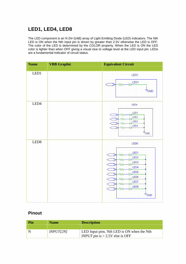
LED1, LED4, LED8
The LED component is an N (N=1|4|8) array of Light Emitting Diode (LED) indicators. The Nth LED is ON when the Nth input pin is driven by greater than 2.5V otherwise the LED is OFF. The color of the LED is determined by the COLOR property. When the LED is ON the LED color is lighter than when OFF giving a visual clue to voltage level at the LED input pin. LEDs are a fundamental indicator of circuit status.
Pinout
Name VBB Graphic Equivalent Circuit
LED1
LED4
LED8
Pin Name Description N INPUT[2N] LED Input pins. Nth LED is ON when the Nth
INPUT pin is > 2.5V else is OFF

Properties
Usage
Name Default Options Description COLOR RED RED | GREEN |
BLUE | YELLOW
Color of LED. LED is lighter when ON than OFF giving a visual clue to the status of the LED.

LedArray
The LED component is an N array of Light Emitting Diode (LED) indicators. The Nth LED is ON when the Nth input pin is driven by greater than 2.5V otherwise the LED is OFF. The color of each individual LED is determined by the COLOR property. When the LED is ON the LED color is lighter than when OFF giving a visual clue to voltage level at the LED input pin. LEDs are a fundamental indicator of circuit status.
Pinout
Properties
Usage
Name VBB Graphic Equivalent Circuit LedArray
Pin Name Description N INPUT[N] LED Input pins. Nth LED is ON when the Nth
INPUT pin is > 2.5V else is OFF
Name Default Options Description Colors RRRR Colors and Length of the Led Array.
A String of length N with letters ‘R’ (Red), ‘G’ (Green) , ‘Y’ (Yellow) or ‘B’ (Blue).


DotMatrixLED8x8
The DotMatrixLED8x8 component is a Dot Matrix LED array. The array consists of 8 Rows and 8 Columsn. Each Row Anode pin drives 8 LEDS each attached to one of the cathode column pins. http://sigma.octopart.com/140413/datasheet/Lumex-LDM-24488NI.pdf
By switching quickly between each row and using the persistence of vision effect a each dot in the matrix can be individually addressed. To emulate the persistence of vision effect VBB only changes the state of the LED when COL is LOW. In this way the COL pin becomes like a latch operation which latches the value of LED.
Pinout
Properties
Name VBB Graphic Equivalent Circuit DotMatrixLED8x8
COL ROW Description LOW HIGH LED ON. LOW LOW LED OFF HIGH Don’t Care No Change.
Pin Name Description Cols Col 0..7 Column Cathode pins of the Dot Matrix array. Rows Row 0..7 Row Anode pins of the Dot Matrix array
Name Default Options Description

Usage
COLOR RED RED | GREEN | BLUE | YELLOW
Color of LED in the array. The default color is red. The options are red,green,blue and yellow but you can also type in any named color

JUMP1, JUMP4, JUMP8
The JUMPER component is an N (N=1|4|8) array of switches which form a short circuit between the Nth input/output pin pair when the Nth Switch = ON and open-circuit O/C when Nth Switch = OFF. JUMPERS are an interactive component. Clicking on the JUMPER switch, the white square region, toggles the value of the JUMPER switch. The SETTINGS property is an N Binary string representing the values of each of the JUMPER switches. Clicking the respective JUMPER switch will change the value of SETTINGS. Alternatively the value can be directly edited in the SETTINGS property textbox.
Name VBB Graphic Equivalent Circuit
JUMP1
JUMP4
JUMP8

Pinout
Properties
Usage
Pin Name Description N IO[2N] JUMPER IO Switch pain. Nth IO pair is short-
circuit where Nth switch is ON, and open-circuit (O/C) when the Nth switch is OFF
Name Default Options Description SETTINGS
[JUMP1] 1 [JUMP4] 1111 [JUMP8] 11111111
<User Entry> N Bit binary string holding JUMPER switches status. Is modified by clicking the component in-place or direct editing in the SETTINGS property textbox.

NumericKeyPad
The KEYPAD4x4 component consists of a Col x Row array of touch switches. The KEYPAD has column connect pins (C1,C2,..Cols-1) and row pins (R1,R2,..Rows-1). Each switch is connected to one column and one row connection pin such that each (row, column) combination is unique for each switch. The appearance of the KEYPAD component is determined by the KEYMASK property which contains a string of the key characters used on the key faces. The currently activated switch is determined by the KEYON property where KEYON = 0 when no switch is connected and KEYON = 1 to (Cols*Rows) when a valid switch is activated. KEYPAD is a user interactive component. Clicking on individual keys will activate the switch for that key. When active the background of the key becomes light green in color giving a visual clue to the state of the key. Only one switch can be active at any one time. Clicking on the currently active switch will toggle the switch to off resulting in no key being selected and KEYON = 0. When a key is on its switch becomes active creating a short-circuit across the unique row, column connection pin combination for that key.
Pinout
Properties
Name VBB Graphic Equivalent Circuit
NumericKeyPad Rows=4 Cols = 4
Pin Name Description C1, C2,..CN Column Connections R1,R2..RN Row Connections
Name Default Options Description Rows 4 <User Entry> The number of Rows of the
KeyPad Cols 4 <User Entry> The number of columns of the
KeyPad KeyMask 123F456E789 <User Entry> Col * Row character string

Usage The switch is connected by pressing a key joining a column and a row. Typically the user scans all columns and row combinations to detect the keypress
DA0BC containing the key-face character for each KEY

Seg7
The SEG7 component is a 7-Segment Display module, which consists of a versatile array of LEDS which can be sequenced to form numbers and a limited form of alphanumeric character. 8 LEDS A, B, C, D, E, F, G, PT are physically arranged on the 7-Segment device. A LED Segment is ON when 5V HIGH is applies its corresponding input pin an is OFF when 0V LOW is applied. When the appropriate patterns are applied to the inputs, 7-Segment display modules are able to display numbers and ASCII characters.
Pinout
Properties
Name VBB Graphic Equivalent Circuit
Pin Name Description 1 A A LED Segment Input. HIGH = ON, LOW = OFF 2 B B LED Segment Input. HIGH = ON, LOW = OFF 3 C C LED Segment Input. HIGH = ON, LOW = OFF 4 D D LED Segment Input. HIGH = ON, LOW = OFF 5 E E LED Segment Input. HIGH = ON, LOW = OFF 6 F F LED Segment Input. HIGH = ON, LOW = OFF 7 G G LED Segment Input. HIGH = ON, LOW = OFF 8 PT PT LED Segment Input. HIGH = ON, LOW = OFF 9 AN Common Cathode. LOW = ON, HIGH = All Off
Name Default Options Description

Usage
Color red red|green|blue|yello
w Sets the color of the LED elements
PT
E
F
A
B
C
D
G

Char A B C D E F G PT HEX 0 1 1 1 1 1 1 0 0 FC 1 0 1 1 0 0 0 0 0 60 2 1 1 0 1 1 0 1 0 DA 3 1 1 1 1 0 0 1 0 F2 4 0 1 1 0 0 1 1 0 66 5 1 0 1 1 0 1 1 0 B6 6 1 0 1 1 1 1 1 0 BE 7 1 1 1 0 0 1 0 0 E4 8 1 1 1 1 1 1 1 0 FE 9 1 1 1 1 0 1 1 0 F6 A 1 1 1 0 1 1 1 0 EE B 0 0 1 1 1 1 1 0 3E C 1 0 0 1 1 1 0 0 9C D 0 1 1 1 1 0 1 0 7A E 1 0 0 1 1 1 1 0 9E F 1 0 0 0 1 1 1 0 8E G 1 0 1 1 1 1 0 0 BC H 0 1 1 0 1 1 1 0 6E I 0 1 1 0 0 0 0 0 60 J 0 1 1 1 1 0 0 0 78 K 0 1 0 1 1 1 1 0 5E L 0 0 0 0 1 1 0 0 06 M 1 0 1 0 1 0 1 0 M N 0 0 1 0 1 0 1 0 N O 0 0 1 1 1 0 1 0 O P 1 1 0 0 1 1 1 0 P Q 1 1 1 0 0 1 1 0 Q R 0 0 0 0 1 0 1 0 R S 1 0 1 1 0 1 1 0 S T 1 0 0 0 1 1 0 0 8C U 0 1 1 1 1 1 0 0 7C V 0 1 1 1 1 1 1 0 7E W 1 1 0 1 1 0 0 0 D8 X 0 0 0 0 1 1 1 0 07 Y 0 1 1 1 0 1 1 0 76 Z 1 0 0 1 0 0 1 0 92 . 0 0 0 0 0 0 0 1 01 + 0 1 1 0 0 0 1 0 62 - 0 0 0 0 0 0 1 0 02 ( 0 0 0 1 1 0 1 0 1A ) 0 0 1 1 0 0 1 0 32 _ 0 0 0 1 0 0 0 0 10 SPACE 0 0 0 0 0 0 0 0 00

DigitalPort
The DigitalPort Component is an instrument which displays the decimal value of the binary value represented by its input pins
Pinout
Properties
Usage
PushButton
Name VBB Graphic Equivalent Circuit DigitalPort
Pin Name Description 1.. PinCount INPUT[PinCount] Port input pins
Name Default Options Description Endian Big
Big|Little
Endian determines the direction of calculation of the value of port
PinCount 8 4|8|16 The number of bits of the port. Pins Bottom Bottom|top Determines if the pins are rendered on
the top or the bottom

The Button component is an interactive switch. Clicking the color panel of the button toggles the value of the POSITION property. The contact type determines the circuit made when the POSITION is ON or OFF. The color of the button is determined by the COLOR property. When POSITION = ON the color is set by ColorOn property and when POSITION =OFF the color is set byt the ColorOff property. When these colors are not the same the color can be used as a visual clue to the state of the button.
Pinout
Name VBB Graphic Equivalent Circuit
Button
Vdd Vdd 1.On 1.Off
2.Off Vdd Vdd
2.On
3.Off Vdd Vdd
3.On
4.Off 4.On
5.On Vdd Vdd
5.Off
6.On 6.Off
Pin Name Description 1. B1 The contact pin for the button

Properties
Usage
Not you can change the size of the buttons using the Scale Up
Name Default Options Description Contact Type 1. On=VDD,
Off=GND 1. On=VDD, Off=GND 2. On=GND, Off=VDD 3. Make VDD 4. Make GND 5. Break VDD 6. Break GND
The contact Type
Button 1. circle 1. circle 2. square 3. left arrow 4. right arrow 5. down arrow 6. up arrow
The graphic of the button.
ColorOn blue Red|green|blue|yellow|NamedColor
Sets the graphic color of the On button. Can be a named color in addition to the option colors
ColorOff black Red|green|blue|yellow|NamedColor
Sets the graphic color of the On button. Can be a named color in addition to the option colors

Switch
The Switch component is an interactive switch. Clicking the switch image toggles the value of the POSITION property. When POSITION = ON a short circuit is present across the IO pins. When POSITION = OFF there is an open-circuit across the IO pins. To give a visual clue to the state of the switch, when POSITION = ON the switch lever in the ON Position or the Bitmap On is shown and when POSITION = OFF the switch lever in the OFF position or Bitmap Off is shown.
Pinout
Properties
Usage
Name VBB Graphic Equivalent Circuit ToggleSwitch
Pin Name Description 1 IO Switch input/output pin 2 IO Switch input/output pin
Name Default Options Description Switch 1. Off 1. Off | 2. On The state of the ToggleSwitch Bitmap On FileDialog for Bitmap
.png | .bmp If set use this Bitmap in the On position
Bitmap Off FileDialog for Bitmap .png | .bmp
If set use this Bitmap in the Off position

PanelMeter
The PanelMeter is a Voltage Meter Instrument with a dial representation of the voltage on its input pin between Vss(left) and Vdd(right) The Panel Meter has the equivalent of a LOW PASS filter on the input pin so can display voltage levels for both absolute voltage levels and PWM equivalent analog voltages
Pinout
Properties
Usage
VBB Graphic Equivalent Circuit
Pin Name Description 1 The voltage sense input pin
Name Default Options Description Shape Square Square | Round The shape of the Panel Meter

SlidePot
The SlidePOT (potentiometer) is a variable voltage divider and consists of two inputs and a single output. The OUTPUT voltage is determined by the input voltages and the value of the POSITION property where OUTPUT = (POSITION x VINA) + ((1 – POSITION) x VINB). Where Property POSITION has a valid range from range from [0..1]. POT is an interactive component. Clicking on POT will set the POSITION property. Clicking on the far left of the POT component corresponds to position 0. Clicking on the far right of the POT component corresponds to position 1. Clicking in-between the left and right will set the POT to a position linearly between 0,1. The POSITION property can also be set using the property editor. You can also drag the POT Knob with the mouse to continuously change the value.
Pinout
Properties
Usage
RotaryPot
VBB Graphic Equivalent Circuit
Pin Name Description 1 INA Input voltage reference 2 INB Input voltage reference 3 OUTPUT Variable output voltage
Name Default Options Description pot 0 0 | 25 | 50 | 75 |
100 | <User Entry>
Potentiometer setting between 0,1 which determines the ratio of INA:INB using in OUTPUT voltage where OUTPUT = (POSITION x VINA) + ((1 – POSITION) x VINB).

The RotaryPOT (potentiometer) is a variable voltage divider connected between Vdd and Vss with a single output. The OUTPUT voltage is determined by the rotation position where OUTPUT = Vdd x (POSITION / Positions ). To rotate the POT you use the mouse to drag the rotation dial.
Pinout
Properties
Usage
JoyStick
The JoyStick component is a model of a regular PC JoyStick with 2 potentiometers on the X and Y axis and button with a pullup resistor. Move the mouse over the keypad to move the JoyStick in X, Y and click the mouse to press the button pulling the button output to ground.
VBB Graphic Equivalent Circuit
Pin Name Description 1 OUTPUT Variable output voltage
Name Default Options Description Positions 12 10 | 12 | 24 | 100 |
<User Entry> The number of positions or steps of the Potentiometer
Position Potentiometer setting between 0,Positions-1 which determines the OUTPUT = Vdd x (POSITION / Positions

Pinout
Properties None
Usage
Relay
The relay component is a model of a SPDT – single pole double throw relay. The drive circuit is included in this ideal model
VBB Graphic Equivalent Circuit
Pin Name Description 1 X X-Axis output Vcc (left) through Vdd (right) 2 B Pulled up button. House mouse down to pull down 3 Y Y-Axis output Vcc (top) through Vdd (bottom)
VBB Graphic Equivalent Circuit

Pinout
Properties None
Usage
MiniTerminal
The mini terminal is a RS232 terminal which can send a receive asynchronous UART communications at TTL levels ie Vdd to Vcc at BAUD. Click on the Green screen segment and type to send messages. When pressing ENTER the characters set in the Enter property are sent. Communications is standard 8,N,1
Pin Name Description 1 ON Relay Solonoid driver circuit 2 A Top contact is connected to C when ON = HIGH 3 C Shared contact point 4 B Bottom contact is connected to C when ON = LOW
Bit0 Bit1 Bit2 Bit3 Bit4 Bit5 Bit6 Bit7 StartBit StopBit
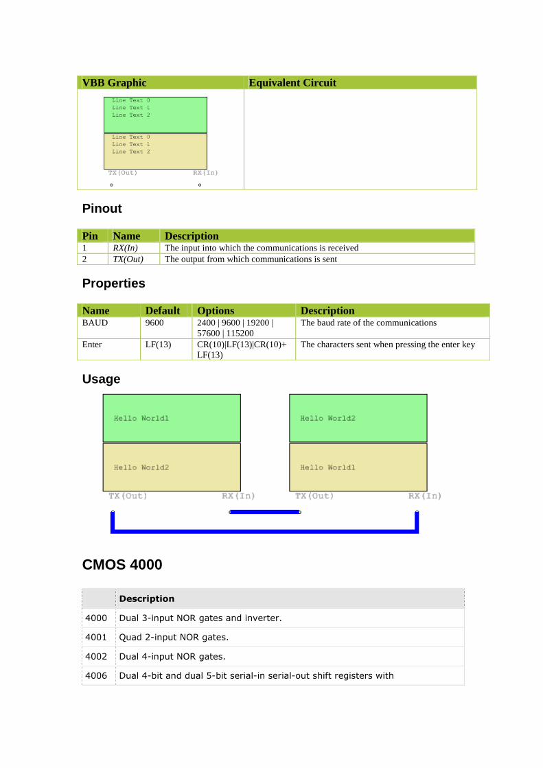
Pinout
Properties
Usage
CMOS 4000
Description
4000 Dual 3-input NOR gates and inverter.
4001 Quad 2-input NOR gates.
4002 Dual 4-input NOR gates.
4006 Dual 4-bit and dual 5-bit serial-in serial-out shift registers with
VBB Graphic Equivalent Circuit
Pin Name Description 1 RX(In) The input into which the communications is received 2 TX(Out) The output from which communications is sent
Name Default Options Description BAUD 9600 2400 | 9600 | 19200 |
57600 | 115200 The baud rate of the communications
Enter LF(13) CR(10)|LF(13)|CR(10)+LF(13)
The characters sent when pressing the enter key
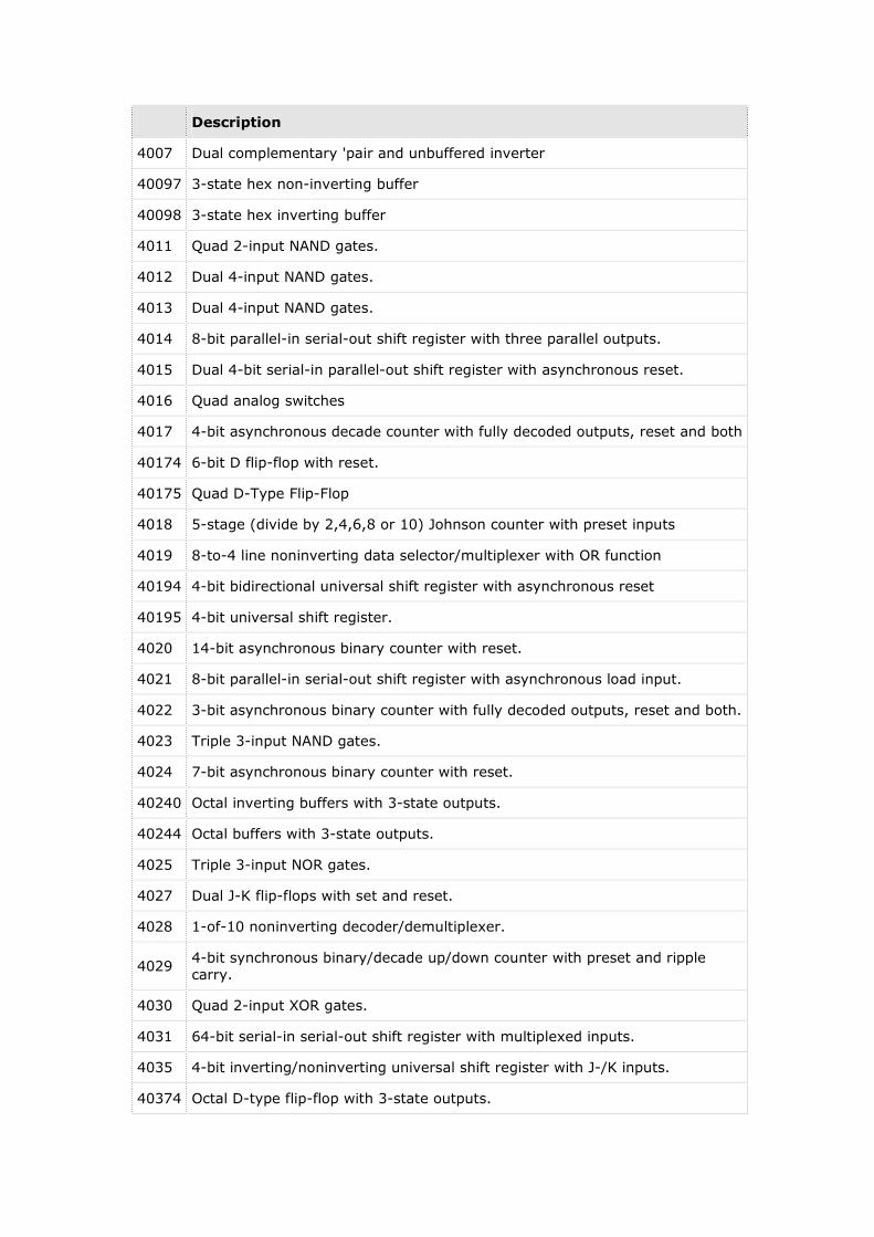
Description
4007 Dual complementary 'pair and unbuffered inverter
40097 3-state hex non-inverting buffer
40098 3-state hex inverting buffer
4011 Quad 2-input NAND gates.
4012 Dual 4-input NAND gates.
4013 Dual 4-input NAND gates.
4014 8-bit parallel-in serial-out shift register with three parallel outputs.
4015 Dual 4-bit serial-in parallel-out shift register with asynchronous reset.
4016 Quad analog switches
4017 4-bit asynchronous decade counter with fully decoded outputs, reset and both
40174 6-bit D flip-flop with reset.
40175 Quad D-Type Flip-Flop
4018 5-stage (divide by 2,4,6,8 or 10) Johnson counter with preset inputs
4019 8-to-4 line noninverting data selector/multiplexer with OR function
40194 4-bit bidirectional universal shift register with asynchronous reset
40195 4-bit universal shift register.
4020 14-bit asynchronous binary counter with reset.
4021 8-bit parallel-in serial-out shift register with asynchronous load input.
4022 3-bit asynchronous binary counter with fully decoded outputs, reset and both.
4023 Triple 3-input NAND gates.
4024 7-bit asynchronous binary counter with reset.
40240 Octal inverting buffers with 3-state outputs.
40244 Octal buffers with 3-state outputs.
4025 Triple 3-input NOR gates.
4027 Dual J-K flip-flops with set and reset.
4028 1-of-10 noninverting decoder/demultiplexer.
4029 4-bit synchronous binary/decade up/down counter with preset and ripple
carry.
4030 Quad 2-input XOR gates.
4031 64-bit serial-in serial-out shift register with multiplexed inputs.
4035 4-bit inverting/noninverting universal shift register with J-/K inputs.
40374 Octal D-type flip-flop with 3-state outputs.

Description
4040 12-bit asynchronous binary counter with reset.
4041 Quad buffers with complementary outputs.
4049 Hex inverters with high-to-low level shifter inputs.
4050 Hex buffers with high-to-low level shifter inputs.
4051 8-to-1 line analog multiplexer/demultiplexer with dual power supply.
4052 8-to-2 line analog multiplexer/demultiplexer with dual power supply.
4053 Triple 2-to-1 line analog multiplexer/demultiplexer with dual power supply.
4066 Quad analog switches.
4067 16-to-1 line analog multiplexer/demultiplexer.
4068 8-input AND/NAND gate with complementary outputs.
4069 Hex inverters.
4070 Quad 2-input XOR gates.
4071 Quad 2-input OR gates.
4072 Dual 4-input OR gates.
4073 Triple 3-input AND gates.
4075 Triple 3-input OR gates.
4076 4-bit 3-state D flip-flop with reset, dual clock enables and dual.
4077 Quad 2-input XNOR gates.
4078 8-input OR/NOR gate with complementary outputs
4081 Quad 2-input AND gates
4082 Dual 4-input AND gates
4085 Dual 3-wide 2/1-input AND-NOR gates
4086 6-wide 2/1-input AND-NOR gate.
4094 8-bit 3-state serial-in parallel-out shift register with output latches.
4502 8-bit 3-state serial-in parallel-out shift register with output latches.
4510 BCD up/down counter.
4511 BCD to 7-segment latch/decoder/driver.
4512 8-input multiplexer with 3-state output.
4514 1-of-16 decoder/demultiplexer with input latches.
4515 1-of-16 decoder/demultiplexer with input latches.
4519 Quadruple 2-input multiplexer.
4539 Dual 4-input multiplexer.

Description
4543 BCD to 7-segment latch/decoder/driver.
4555 Dual 1-of-4 decoder/demultiplexer.
4556 Dual 1-of-4 decoder/demultiplexer.
4731 Quadruple 64-bit static shift register.