Embed Size (px)
Citation preview
Locking Plate SystemVariAx Distal Fibula
Operative Technique
Foot
& A
nkle
• Distal Fibula Fracture Repair• Polyaxial Locking Technology• Low Profi le Design• VariAx 2 One Th ird Tubular
Plating System
• Low Profi le Design• VariAx 2 One Th ird Tubular
Plating System
Contributing SurgeonBradley R. Merk, MD Associate Professor of Orthopaedic Surgery Director of Orthopaedic Trauma Feinberg School of Medicine Northwestern University Chicago, USA
John Early, MD Clinical Professor of Orthopaedic Surgery, University of Texas South Western Medical Centre,Dallas, USA
VariAx Distal Fibula Locking Plate System
This publication sets forth detailed recommended procedures for using Stryker devices and instruments.
It offers guidance that you should heed, but, as with any such technical guide, each surgeon must consider the particular needs of each patient and make appropriate adjustments when and as required.
A workshop training is recommended prior to performing your first surgery.
All non-sterile devices must be cleaned and sterilized before use. Follow the instructions provided in our reprocessing guide (L24002000). Multi-component instruments must be disassembled for cleaning.
Please refer to the corresponding assembly / disassembly instructions. Please remember that the compatibility of different product systems have not been tested unless specified otherwise in the product labeling.
See package insert (Instruction for Use) [V15011, V15013, 90-03300] for a complete list of potential adverse effects, contraindications, warnings and precautions. The surgeon must discuss all relevant risks including the finite lifetime of the device with the patient when necessary.
2
Page
1. VariAx Distal Fibula Indications / Precautions / Contraindications 4
2. VariAx Distal Fibula Introduction 5
3. VariAx 2 One Third Tubular Indications / Precautions / Contraindications 6
4. Overview 7
5. Operative Technique 8
Planning and Preparation 8
Lateral Plate Positioning 9
Posterior Lateral Plate Placement 9
Preparation for Screw Insertion 10
Screw Insertion 13
Final Steps 13
Optional: Independent Lag Screw Technique 14
Optional: Syndesmotic Screw Fixation Technique 16
Table of Contents
3
Indications, Precautions & Contraindications VariAx Distal Fibula Locking Plate System
Th e VariAx Distal Lateral Plate is intended for use in internal fi xation of the distal fi bula.Th e VariAx Fibula Straight Plates are intended for use in internal fi xation of the distal fi bula.
IndicationsSee package insert for warnings, precautions, adverse eff ects and other essential product information.Stryker Systems have not been evaluated for safety and compatibility in Magnetic Resonance (MR) environment and have not been tested for heating or migration in the MR environment.• Obesity. An overweight or obese
patient can produce loads on the implant that can lead to failure of the fi xation of the device or to failure of the device itself
• Patients having inadequate tissue coverage over the operative site
• Implant utilization that would interfere with anatomical structures or physiological performance
• Any mental or neuromuscular disorder which would create an unacceptable risk of fi xation failure or complications in postoperative care
• Other medical or surgical conditions which would preclude the potential benefi t of surgery
Warnings & Precautions
ContraindicationsTh e physician’s education, training and professional judgement must be relied upon to choose the most appropriate device and treatment. Conditions presenting an increased risk of failure include:• Any active or suspected latent
infection or marked local infl ammation in or about the aff ected area
• Compromised vascularity that would inhibit adequate blood supply to the fracture or the operative site
• Bone stock compromised by disease, infection or prior implantation that can not provide adequate support and / or fi xation of the devices
• Material sensitivity, documentedor suspected
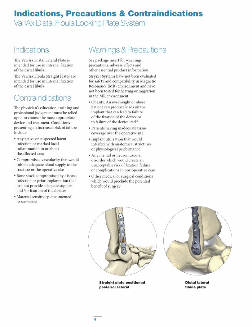
Distal lateral fi bula plate
Straight plate positioned posterior lateral
4
Indications, Precautions & Contraindications VariAx Distal Fibula Locking Plate System
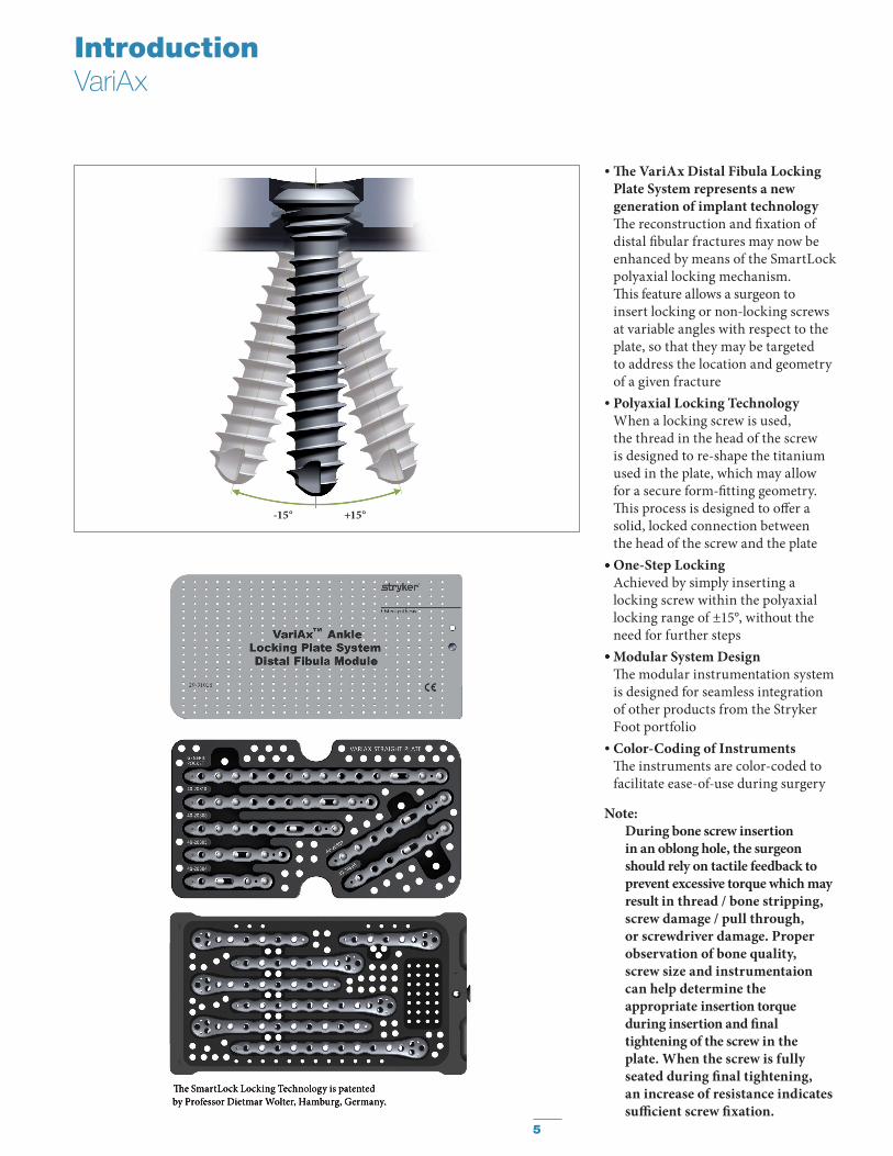
• Th e VariAx Distal Fibula Locking Plate System represents a new generation of implant technology Th e reconstruction and fi xation of distal fi bular fractures may now be enhanced by means of the SmartLock polyaxial locking mechanism. Th is feature allows a surgeon to insert locking or non-locking screws at variable angles with respect to the plate, so that they may be targeted to address the location and geometry of a given fracture
• Polyaxial Locking Technology When a locking screw is used, the thread in the head of the screw is designed to re-shape the titanium used in the plate, which may allow for a secure form-fi tting geometry. Th is process is designed to off er a solid, locked connection between the head of the screw and the plate
• One-Step Locking Achieved by simply inserting a locking screw within the polyaxial locking range of ±15°, without the need for further steps
• Modular System Design Th e modular instrumentation system is designed for seamless integration of other products from the Stryker Foot portfolio
• Color-Coding of Instruments Th e instruments are color-coded to facilitate ease-of-use during surgery
Note: During bone screw insertion
in an oblong hole, the surgeon should rely on tactile feedback to prevent excessive torque which may result in thread / bone stripping, screw damage / pull through, or screwdriver damage. Proper observation of bone quality, screw size and instrumentaion can help determine the appropriate insertion torque during insertion and fi nal tightening of the screw in the plate. When the screw is fully seated during fi nal tightening, an increase of resistance indicates suffi cient screw fi xation.
Th e SmartLock Locking Technology is patented by Professor Dietmar Wolter, Hamburg, Germany.
IntroductionVariAx
-15° +15°
Th e SmartLock Locking Technology is patented by Professor Dietmar Wolter, Hamburg, Germany.
•
•
5
Indications, Precautions & ContraindicationsVariAx 2 One Third Tubular Plating System
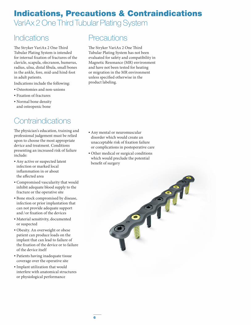
IndicationsTh e Stryker VariAx 2 One-Th ird Tubular Plating System is intended for internal fi xation of fractures of the clavicle, scapula, olecranon, humerus, radius, ulna, distal fi bula, small bones in the ankle, fore, mid-and hind-foot in adult patients.Indications include the following:• Osteotomies and non-unions• Fixation of fractures• Normal bone density
and osteopenic bone
PrecautionsTh e Stryker VariAx 2 One Th ird Tubular Plating System has not been evaluated for safety and compatibility in Magnetic Resonance (MR) environment and have not been tested for heating or migration in the MR environment unless specifi ed otherwise in the product labeling.
ContraindicationsTh e physician’s education, training and professional judgement must be relied upon to choose the most appropriate device and treatment. Conditions presenting an increased risk of failure include:• Any active or suspected latent
infection or marked local infl ammation in or about the aff ected area
• Compromised vascularity that would inhibit adequate blood supply to the fracture or the operative site
• Bone stock compromised by disease, infection or prior implantation that can not provide adequate support and / or fi xation of the devices
• Material sensitivity, documented or suspected
• Obesity. An overweight or obese patient can produce loads on the implant that can lead to failure of the fi xation of the device or to failure of the device itself
• Patients having inadequate tissue coverage over the operative site
• Implant utilization that would interfere with anatomical structures or physiological performance
• Any mental or neuromuscular disorder which would create an unacceptable risk of fi xation failure or complications in postoperative care
• Other medical or surgical conditions which would preclude the potential benefi t of surgery
6
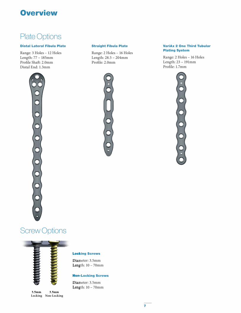
Plate Options
Overview
Distal Lateral Fibula Plate
Range: 3 Holes – 12 HolesLength: 77 – 185mmProfi le Shaft : 2.0mmDistal End: 1.3mm
Straight Fibula Plate
Range: 2 Holes – 16 HolesLength: 28.5 – 204mmProfi le: 2.0mm
Locking Screws
Diameter: 3.5mmLength: 10 – 70mm
Non-Locking Screws
Diameter: 3.5mmLength: 10 – 70mm
VariAx 2 One Third Tubular Plating System
Range: 2 Holes – 16 HolesLength: 23 – 191mmProfi le: 1.7mm
Screw Options
3.5mmLocking
3.5mmNon-Locking
Locking Screws
Diameter: 3.5mmLength: 10 – 70mm
Non-Locking Screws
Diameter: 3.5mmLength: 10 – 70mm
3.5mm 3.5mm
7
Planning and Preparation
Th e Operative Technique listed below is designed to provide a general overview on the instruments and procedure required to implant a plate in the distal fi bula.
Th is operative technique will focus on the placement and fi xation of the Straight Fibula plate and Distal Lateral Fibula Plate. Th e VariAx 2 One Th ird Tubular Plating system uses the same techniques and instrumentation.
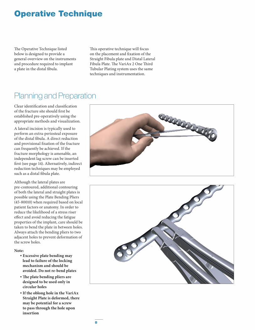
Clear identifi cation and classifi cation of the fracture site should fi rst be established pre-operatively using the appropriate methods and visualization.
A lateral incision is typically used to perform an extra-periosteal exposure of the distal fi bula. A direct reduction and provisional fi xation of the fracture can frequently be achieved. If the fracture morphology is amenable, an independent lag screw can be inserted fi rst (see page 14). Alternatively, indirect reduction techniques may be employed such as a distal fi bula plate.
Although the lateral plates are pre-contoured, additional contouring of both the lateral and straight plates is possible using the Plate Bending Pliers (45-80010) when required based on local patient factors or anatomy. In order to reduce the likelihood of a stress riser eff ect and avoid reducing the fatigue properties of the implant, care should be taken to bend the plate in between holes. Always attach the bending pliers to two adjacent holes to prevent deformation of the screw holes.
Note: • Excessive plate bending may
lead to failure of the locking mechanism and should be avoided. Do not re-bend plates
• Th e plate bending pliers are designed to be used only in circular holes
• If the oblong hole in the VariAx Straight Plate is deformed, there may be potential for a screw to pass through the hole upon insertion
Operative Technique
8
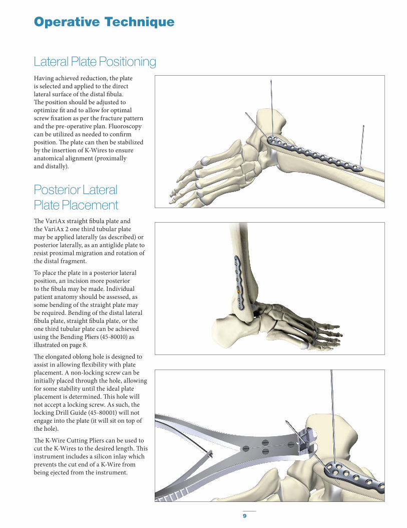
Having achieved reduction, the plate is selected and applied to the direct lateral surface of the distal fi bula. Th e position should be adjusted to optimize fi t and to allow for optimal screw fi xation as per the fracture pattern and the pre-operative plan. Fluoroscopy can be utilized as needed to confi rm position. Th e plate can then be stabilized by the insertion of K-Wires to ensure anatomical alignment (proximally and distally).
Operative Technique
Lateral Plate Positioning
Posterior Lateral Plate PlacementTh e VariAx straight fi bula plate and the VariAx 2 one third tubular plate may be applied laterally (as described) or posterior laterally, as an antiglide plate to resist proximal migration and rotation of the distal fragment.
To place the plate in a posterior lateral position, an incision more posterior to the fi bula may be made. Individual patient anatomy should be assessed, as some bending of the straight plate may be required. Bending of the distal lateral fi bula plate, straight fi bula plate, or the one third tubular plate can be achieved using the Bending Pliers (45-80010) as illustrated on page 8.
Th e elongated oblong hole is designed to assist in allowing fl exibility with plate placement. A non-locking screw can be initially placed through the hole, allowing for some stability until the ideal plate placement is determined. Th is hole will not accept a locking screw. As such, the locking Drill Guide (45-80001) will not engage into the plate (it will sit on top of the hole).
Th e K-Wire Cutting Pliers can be used to cut the K-Wires to the desired length. Th is instrument includes a silicon inlay which prevents the cut end of a K-Wire from being ejected from the instrument.
9
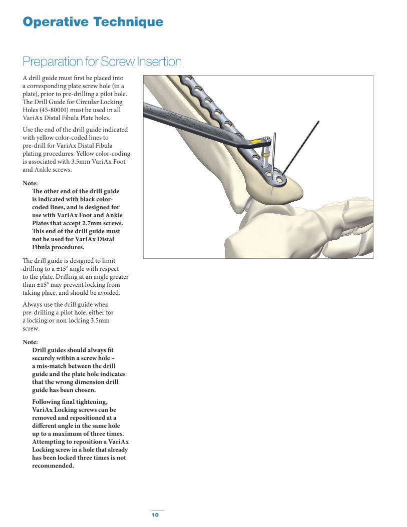
A drill guide must fi rst be placed into a corresponding plate screw hole (in a plate), prior to pre-drilling a pilot hole. Th e Drill Guide for Circular Locking Holes (45-80001) must be used in all VariAx Distal Fibula Plate holes.
Use the end of the drill guide indicated with yellow color-coded lines to pre-drill for VariAx Distal Fibula plating procedures. Yellow color-coding is associated with 3.5mm VariAx Foot and Ankle screws.
Note: Th e other end of the drill guide is indicated with black color-coded lines, and is designed for use with VariAx Foot and Ankle Plates that accept 2.7mm screws. Th is end of the drill guide must not be used for VariAx Distal Fibula procedures.
Th e drill guide is designed to limit drilling to a ±15° angle with respect to the plate. Drilling at an angle greater than ±15° may prevent locking from taking place, and should be avoided.
Always use the drill guide whenpre-drilling a pilot hole, either for a locking or non-locking 3.5mm screw.
Note:Drill guides should always fi tsecurely within a screw hole – a mis-match between the drill guide and the plate hole indicates that the wrong dimension drill guide has been chosen.
Following fi nal tightening, VariAx Locking screws can be removed and repositioned at a diff erent angle in the same hole up to a maximum of three times. Attempting to reposition a VariAx Locking screw in a hole that already has been locked three times is not recommended.
Preparation for Screw Insertion
Operative Technique
10
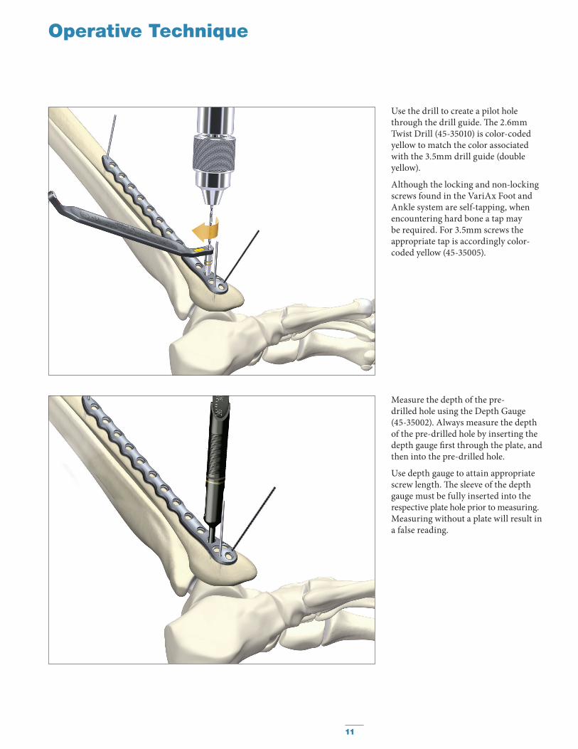
Use the drill to create a pilot hole through the drill guide. Th e 2.6mm Twist Drill (45-35010) is color-coded yellow to match the color associated with the 3.5mm drill guide (double yellow).
Although the locking and non-locking screws found in the VariAx Foot and Ankle system are self-tapping, when encountering hard bone a tap may be required. For 3.5mm screws the appropriate tap is accordingly color-coded yellow (45-35005).
Measure the depth of the pre-drilled hole using the Depth Gauge (45-35002). Always measure the depth of the pre-drilled hole by inserting the depth gauge fi rst through the plate, and then into the pre-drilled hole.
Use depth gauge to attain appropriate screw length. Th e sleeve of the depth gauge must be fully inserted into therespective plate hole prior to measuring. Measuring without a plate will result in a false reading.
Operative Technique
11
Operative Technique
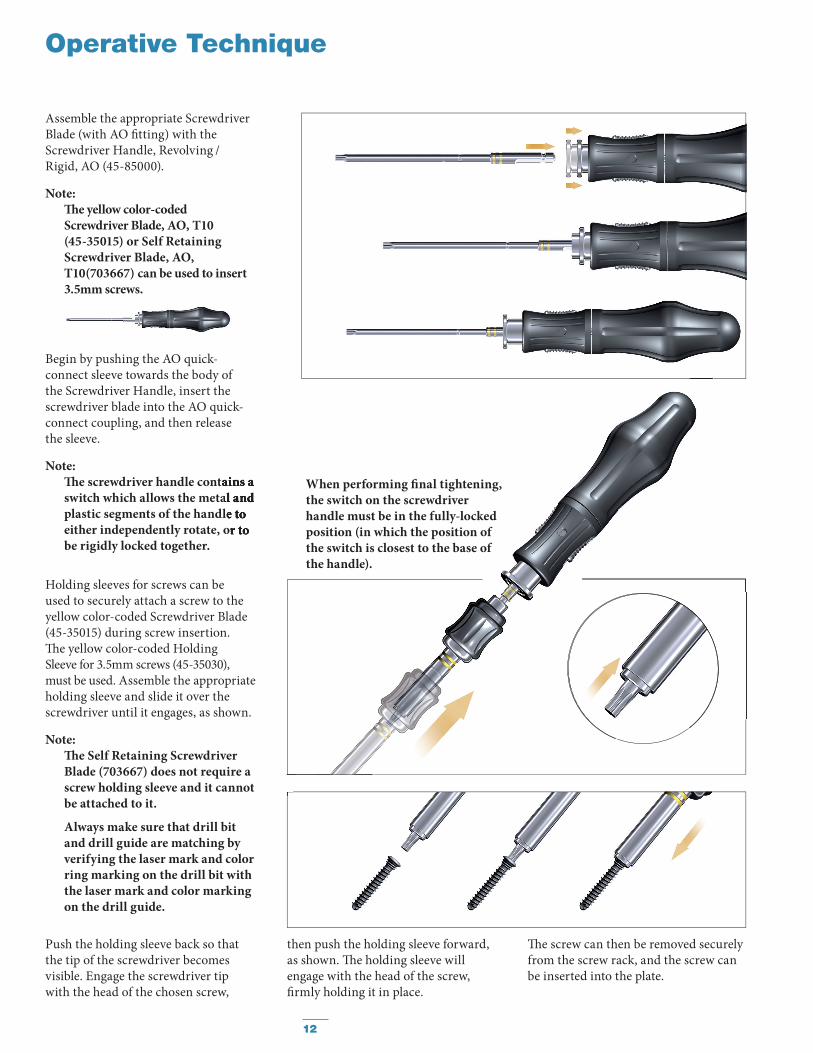
Assemble the appropriate Screwdriver Blade (with AO fi tting) with the Screwdriver Handle, Revolving /Rigid, AO (45-85000).
Note: Th e yellow color-coded Screwdriver Blade, AO, T10(45-35015) or Self Retaining Screwdriver Blade, AO, T10(703667) can be used to insert 3.5mm screws.
Begin by pushing the AO quick-connect sleeve towards the body of the Screwdriver Handle, insert the screwdriver blade into the AO quick-connect coupling, and then release the sleeve.
Note:Th e screwdriver handle contains a switch which allows the metal and plastic segments of the handle to either independently rotate, or to be rigidly locked together.
Push the holding sleeve back so that the tip of the screwdriver becomes visible. Engage the screwdriver tipwith the head of the chosen screw,
Th e screw can then be removed securely from the screw rack, and the screw can be inserted into the plate.
Th e screwdriver handle contains a switch which allows the metal and plastic segments of the handle to either independently rotate, or to
Holding sleeves for screws can be used to securely attach a screw to the yellow color-coded Screwdriver Blade (45-35015) during screw insertion.Th e yellow color-coded Holding Sleeve for 3.5mm screws (45-35030), must be used. Assemble the appropriate holding sleeve and slide it over the screwdriver until it engages, as shown.
Note: Th e Self Retaining Screwdriver
Blade (703667) does not require a screw holding sleeve and it cannot be attached to it.
Always make sure that drill bit and drill guide are matching by verifying the laser mark and color ring marking on the drill bit with the laser mark and color marking on the drill guide.
When performing fi nal tightening, the switch on the screwdriver handle must be in the fully-locked position (in which the position of the switch is closest to the base of the handle).
then push the holding sleeve forward, as shown. Th e holding sleeve willengage with the head of the screw, fi rmly holding it in place.
12
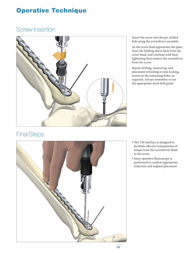
Screw InsertionInsert the screw into the pre-drilled hole using the screwdriver assembly.
As the screw head approaches the plate, draw the holding sleeve back from the screw head, and continue with fi nal tightening then remove the screwdriver from the screw.
Repeat drilling, measuring, and placement of locking or non-locking screws in the remaining holes, as required. Always remember to use the appropriate sized drill guide.
Operative Technique
Final Steps• Th e T10 interface is designed to
facilitate eff ective transmission of torque from the screwdriver blade to the screw
• Intra-operative fl uoroscopy is performed to confi rm appropriate reduction and implant placement
13
Optional: Independent Lag Screw Technique
Operative Technique
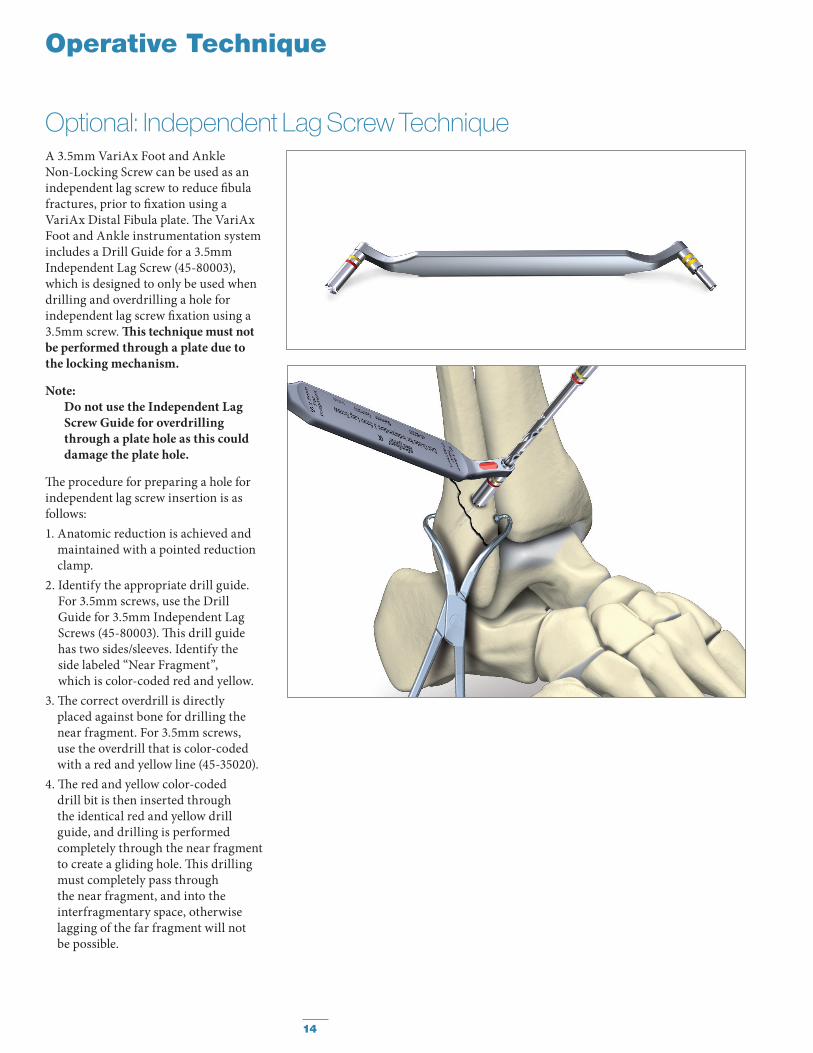
A 3.5mm VariAx Foot and Ankle Non-Locking Screw can be used as an independent lag screw to reduce fi bula fractures, prior to fi xation using a VariAx Distal Fibula plate. Th e VariAx Foot and Ankle instrumentation system includes a Drill Guide for a 3.5mm Independent Lag Screw (45-80003), which is designed to only be used when drilling and overdrilling a hole for independent lag screw fi xation using a 3.5mm screw. Th is technique must not be performed through a plate due to the locking mechanism.
Note:Do not use the Independent Lag Screw Guide for overdrilling through a plate hole as this could damage the plate hole.
Th e procedure for preparing a hole for independent lag screw insertion is as follows:1. Anatomic reduction is achieved and
maintained with a pointed reduction clamp.
2. Identify the appropriate drill guide. For 3.5mm screws, use the Drill Guide for 3.5mm Independent Lag Screws (45-80003). Th is drill guide has two sides/sleeves. Identify the side labeled “Near Fragment”, which is color-coded red and yellow.
3. Th e correct overdrill is directly placed against bone for drilling the near fragment. For 3.5mm screws, use the overdrill that is color-coded with a red and yellow line (45-35020).
4. Th e red and yellow color-coded drill bit is then inserted through the identical red and yellow drill guide, and drilling is performed completely through the near fragment to create a gliding hole. Th is drilling must completely pass through the near fragment, and into the interfragmentary space, otherwise lagging of the far fragment will not be possible.
14
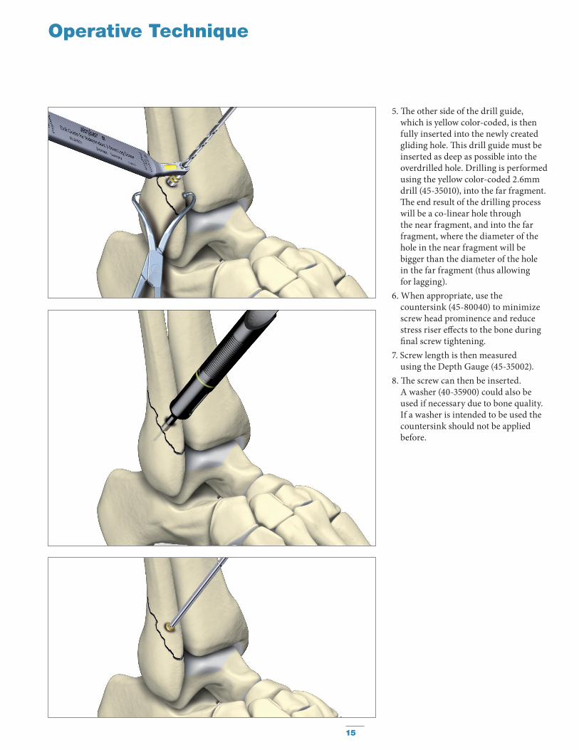
5. Th e other side of the drill guide, which is yellow color-coded, is then fully inserted into the newly created gliding hole. Th is drill guide must be inserted as deep as possible into the overdrilled hole. Drilling is performed using the yellow color-coded 2.6mm drill (45-35010), into the far fragment. Th e end result of the drilling process will be a co-linear hole through the near fragment, and into the far fragment, where the diameter of the hole in the near fragment will be bigger than the diameter of the hole in the far fragment (thus allowing for lagging).
6. When appropriate, use the countersink (45-80040) to minimize screw head prominence and reduce stress riser eff ects to the bone during fi nal screw tightening.
7. Screw length is then measured using the Depth Gauge (45-35002).
8. Th e screw can then be inserted.A washer (40-35900) could also be used if necessary due to bone quality. If a washer is intended to be used the countersink should not be applied before.
Operative Technique
15
Operative Technique
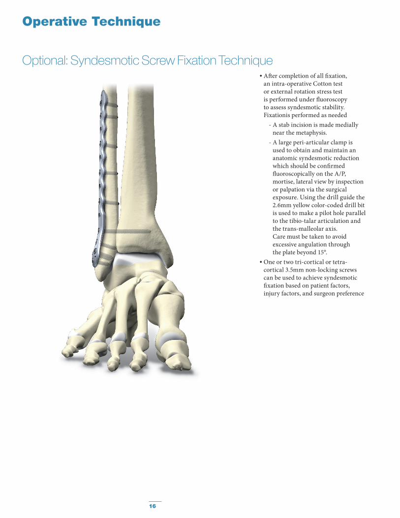
Optional: Syndesmotic Screw Fixation Technique• After completion of all fixation,
an intra-operative Cotton test or external rotation stress test is performed under fluoroscopy to assess syndesmotic stability. Fixationis performed as needed
- A stab incision is made medially near the metaphysis.
- A large peri-articular clamp is used to obtain and maintain an anatomic syndesmotic reduction which should be confirmed fluoroscopically on the A/P, mortise, lateral view by inspection or palpation via the surgical exposure. Using the drill guide the 2.6mm yellow color-coded drill bit is used to make a pilot hole parallel to the tibio-talar articulation and the trans-malleolar axis. Care must be taken to avoid excessive angulation through the plate beyond 15°.
• One or two tri-cortical or tetra-cortical 3.5mm non-locking screws can be used to achieve syndesmotic fixation based on patient factors, injury factors, and surgeon preference
16

Notes
17

Notes
18

Notes
19
Th is document is intended solely for the use of healthcare professionals. A surgeon must always rely on his or her own professional clinical judgment when deciding whether to use a particular product when treating a particular patient. Stryker does not dispense medical advice and recommends that surgeons be trained in the use of any particular product before using it in surgery. Th e information presented is intended to demonstrate a Stryker product. A surgeon must always refer to the package insert, product label and/or instructions for use, including the instructions for Cleaning and Sterilization (if applicable), before using any Stryker product. Products may not be available in all markets because product availability is subject to the regulatory and/or medical practices in individual markets. Please contact your Stryker representative if you have questions about the availability of Stryker products in your area.
Stryker Corporation or its divisions or other corporate affi liated entities own, use or have applied for the following trademarks or service marks: SmartLock, Stryker, VariAx. All other trademarks are trademarks of their respective owners or holders.
Th e products listed above are CE marked.
Content ID: VAX-ST-33, 07-2015 (former Content ID VAX-ST-10)
Copyright © 2015 Stryker
Manufactured by:
Stryker GmbHBohnackerweg 12545 SelzachSwitzerland
www.stryker.com
0123