Embed Size (px)
Citation preview
Components
Introduction2
Vacuum Express3
ConFlat® Flanges and Fittings4-44
Wheeler Flanges45
Klamp Flanges and Fittings46-76
ISO Flanges and Fittings77-93
Feedthroughs94-95
Supplies96-98
Varian, Inc.Vacuum Technologies
Varian Flanges
2
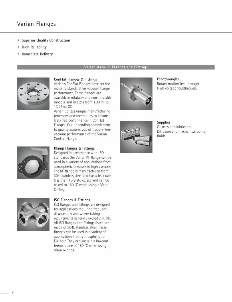
• Superior Quality Construction
• High Reliability
• Immediate Delivery
Varian Vacuum Flanges and Fittings
ConFlat Flanges & FittingsVarian’s ConFlat Flanges have set theindustry standard for vacuum flangeperformance. These flanges areavailable in rotatable and non-rotatablemodels, and in sizes from 1.33 in. to13.25 in. OD.Varian utilizes unique manufacturingprocesses and techniques to ensureleak-free performance in ConFlatFlanges. Our unbending commitmentto quality assures you of trouble-freevacuum performance of the VarianConFlat Flange.
Klamp Flanges & FittingsDesigned in accordance with ISOstandards the Varian KF flange can beused in a variety of applications fromatmospheric pressure to high vacuum.The KF flange is manufactured from304 stainless steel and has a leak rateless than 1E-9 std cc/sec and can bebaked to 150 °C when using a VitonO-Ring.
ISO Flanges & FittingsISO flanges and fittings are designedfor applications requiring frequentdisassembly and where tubingrequirements generally exceed 2 in. OD. All ISO flanges and fittings listed aremade of 304L stainless steel. Theseflanges can be used in a variety ofapplications from atmospheric to E-8 torr. They can sustain a bakeouttemperature of 150 °C when usingViton o-rings.
FeedthroughsRotary motion feedthrough.High voltage feedthrough.
SuppliesGreases and lubricants.Diffusion and mechanical pumpfluids.
Com
pone
nts
ComponentsF langes
3Varian, Inc. Vacuum Technologies
Your vacuum hardware order shipped in 24 hours or less!
Ordering• Flanges and fittings can be ordered by calling
Varian directly, or through your local Varian Sales Engineeror Representative.
• Select flanges and fittings can also be ordered on-linethrough Varian’s web-site.
Delivery• Hundreds of popular vacuum components in stock• We ship from our Lexington, MA facility within 24 hours…
or we will deliver your order at your convenience
Quality• High Quality ConFlat, ISO, and KF Flanges and Fittings• Varian’s State-of-the-Art Manufacturing and
Distribution Facility• Efficient, reliable, quality manufacturing processes and
techniques including Statistical Process Control (SPC) and Process Capability Index (CpK)
Varian ConFlat Flanges
4
ConFlat FlangesVarian’s ConFlat Flanges have set the industry standard forvacuum flange performance. These flanges are available inrotatable and non-rotatable models, and in sizes from 1.33 in.to 13.25 in. OD.
Varian utilizes unique manufacturing processes andtechniques to ensure leak-free performance in ConFlatFlanges. Our flanges are manufactured from type 304 ESR or304L stainless steel. ESR stainless steel is manufactured usinga process known as Electro Slag Remelting. This process is afurther refinement of the stainless steel and results in higherpurity, fewer inclusions, a more uniform grain structure, andgenerally improved properties. Electro Slag Remelting alsomarkedly reduces nonmetallic inclusions, oxygen content,sulfur, and micro and macro segregations.304 ESR flanges are recommended for electro-platingapplications when the flanges are not masked-off.
Each lot of raw material is carefully evaluated forperformance prior to use in manufacturing. Only uponacceptance will this material be used for ConFlat Flangeproduction. Our unbending commitment to quality assuresyou of trouble-free vacuum performance of the VarianConFlat Flange.
ConFlat Flange FittingsA large variety of fittings are immediately available for yourvacuum application. Varian’s ConFlat Flange vacuum fittingsoffer the same vacuum performance as our ConFlat Flange.Combined with our excellence in vacuum componentfabrication, these fittings offer high reliability andperformance for your application.
Specifications
MaterialsFlanges: ConFlat Flange are available in 304L Stainless Steeland 304 Stainless Electro-Slag Remelt (ESR). Larger flangesmay be made from open-die or cross-forged type 304Stainless. Rotatable flanges in ESR may include receiversmade from 304 bar or plate.
Other materials, such as 316LN SS, are also available.
Gaskets: Copper gaskets are made from electronic gradeOFHC copper with a “Purity Total” of greater than 99.99%.
Viton Gaskets: Reusable gaskets for leak checking and use inunbaked applications are also available.
Hardware: Bolt options include 12-point high tensilestrength, hexagonal head, or metric hexagonal head. Washersare not required with 1.33 in. (NW16 CF) and 2.75 in. (NW25CF) OD flanges.
PerformanceVacuum Range: Atmospheric to 1 x 10-13 Torr (mbar). No leak detectable on mass spectrometer leak detector withsensitivity of 2 x 10⁻¹⁰ std cc/sec.
Temperature Range: 304 ESR SS can be repeatedly cycledfrom –196° C to +500° C.
Packaging: All Varian components are cleaned via anultrasonic aqueous base cleaning system using de-ionizedwater. Water soluble coolants and non-sulphur basedcompounds are used in our manufacturing processes. Our parts are free of visible particulates, debris, oils andgreases, and are ready for use in vacuum systems.
Com
pone
nts
ComponentsConFlat® F langes
5Varian, Inc. Vacuum Technologies
ConFlat Flanges & Fittings Page
ConFlat Flanges ................................................................................... 6Reducing Flanges ................................................................................ 24ConFlat Flange Accessory Dimensions ....................................... 26Bolt/Nut Sets – Reducing Flanges................................................ 27Bolt Torques........................................................................................... 27Reducing Nipples – 304 Steel and 316LN SS........................... 28Half Nipples .......................................................................................... 29Nipples .................................................................................................... 30Elbows (90°) ........................................................................................... 31Tees .......................................................................................................... 32Crosses (4-Way) ................................................................................... 32Flexible Couplings .............................................................................. 33CFF to KF Adapters ............................................................................ 35UHV Compression Ports.................................................................... 38ConFlat to Compression Port Adapters ...................................... 39O-Ring Sealed Vacuum Compression Ports and Blank-offs 40Viewports................................................................................................ 41Glass Adapters ...................................................................................... 44
Wheeler Flanges Page
UHV Wire-sealed flanges ................................................................. 45
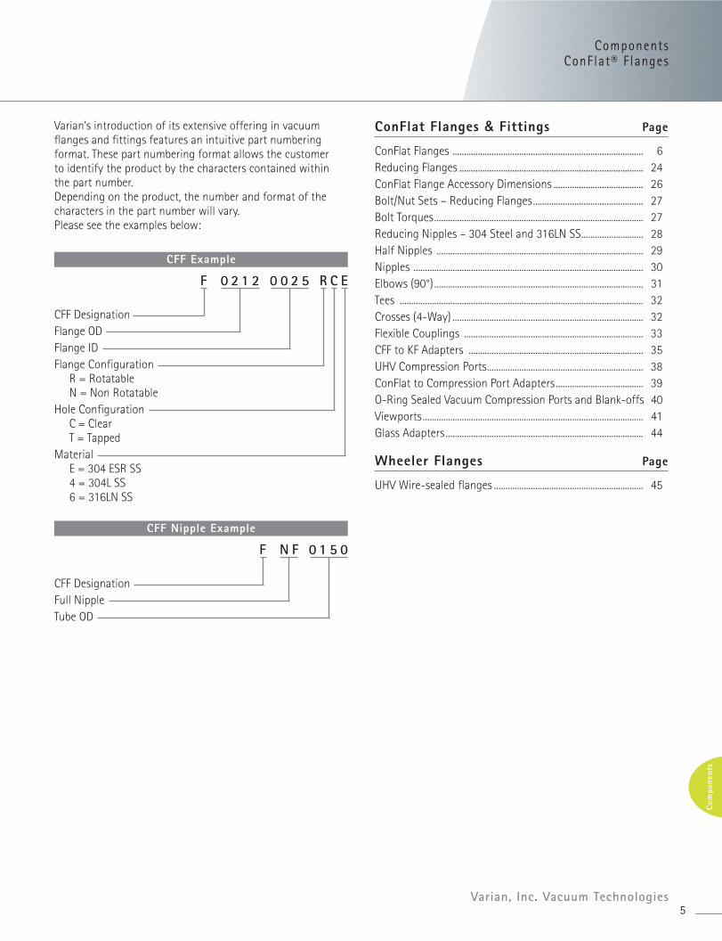
CFF Example
F 0 2 1 2 0 0 2 5 R C E
CFF DesignationFlange ODFlange IDFlange Configuration
R = RotatableN = Non Rotatable
Hole ConfigurationC = ClearT = Tapped
MaterialE = 304 ESR SS4 = 304L SS6 = 316LN SS
Varian’s introduction of its extensive offering in vacuumflanges and fittings features an intuitive part numberingformat. These part numbering format allows the customer to identify the product by the characters contained within the part number.Depending on the product, the number and format of thecharacters in the part number will vary. Please see the examples below:
CFF Nipple Example
F N F 0 1 5 0
CFF DesignationFull NippleTube OD
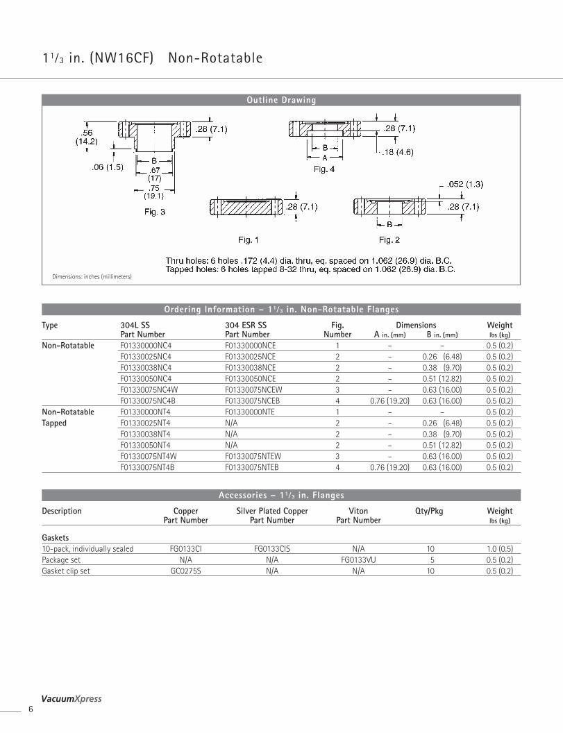
11⁄3 in. (NW16CF) Non-Rotatable
6
Dimensions: inches (millimeters)
Outline Drawing
Type 304L SS 304 ESR SS Fig. Dimensions WeightPart Number Part Number Number A in. (mm) B in. (mm) lbs (kg)
Non-Rotatable F01330000NC4 F01330000NCE 1 – – 0.5 (0.2)F01330025NC4 F01330025NCE 2 – 0.26 (6.48) 0.5 (0.2)F01330038NC4 F01330038NCE 2 – 0.38 (9.70) 0.5 (0.2)F01330050NC4 F01330050NCE 2 – 0.51 (12.82) 0.5 (0.2)F01330075NC4W F01330075NCEW 3 – 0.63 (16.00) 0.5 (0.2)F01330075NC4B F01330075NCEB 4 0.76 (19.20) 0.63 (16.00) 0.5 (0.2)
Non-Rotatable F01330000NT4 F01330000NTE 1 – – 0.5 (0.2)Tapped F01330025NT4 N/A 2 – 0.26 (6.48) 0.5 (0.2)
F01330038NT4 N/A 2 – 0.38 (9.70) 0.5 (0.2)F01330050NT4 N/A 2 – 0.51 (12.82) 0.5 (0.2)F01330075NT4W F01330075NTEW 3 – 0.63 (16.00) 0.5 (0.2)F01330075NT4B F01330075NTEB 4 0.76 (19.20) 0.63 (16.00) 0.5 (0.2)
Ordering Information – 11⁄3 in. Non-Rotatable Flanges
Description Copper Silver Plated Copper Viton Qty/Pkg WeightPart Number Part Number Part Number lbs (kg)
Gaskets10-pack, individually sealed FG0133CI FG0133CIS N/A 10 1.0 (0.5)Package set N/A N/A FG0133VU 5 0.5 (0.2)Gasket clip set GC0275S N/A N/A 10 0.5 (0.2)
Accessories – 11⁄3 in. Flanges
ComponentsConFlat® F langes
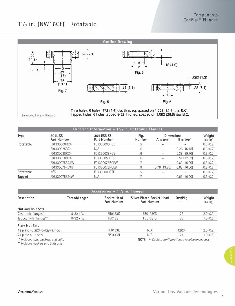
11⁄3 in. (NW16CF) Rotatable
7Varian, Inc. Vacuum Technologies
Com
pone
nts
Dimensions: inches (millimeters)
Outline Drawing
Type 304L SS 304 ESR SS Fig. Dimensions WeightPart Number Part Number Number A in. (mm) B in. (mm) lbs (kg)
Rotatable F01330000RC4 F01330000RCE 5 – – 0.5 (0.2)F01330025RC4 N/A 6 – 0.26 (6.48) 0.5 (0.2)F01330038RC4 F01330038RCE 6 – 0.38 (9.70) 0.5 (0.2)F01330050RC4 F01330050RCE 6 – 0.51 (12.82) 0.5 (0.2)F01330075RC4W F01330075RCEW 7 – 0.63 (16.00) 0.5 (0.2)F01330075RC4B F01330075RCEB 8 0.76 (19.20) 0.63 (16.00) 0.5 (0.2)
Rotatable N/A F01330000RTE 5 – – 0.5 (0.2)Tapped F01330075RT4W N/A 7 – 0.63 (16.00) 0.5 (0.2)
Ordering Information – 11⁄3 in. Rotatable Flanges
Description Thread/Length Socket Head Silver Plated Socket Head Qty/Pkg WeightPart Number Part Number lbs (kg)
Nut and Bolt SetsClear hole flanges* 8-32 x 3⁄4 FB0133C FB0133CS 25 2.0 (0.9)Tapped hole flanges** 8-32 x 1⁄2 FB0133T FB0133TS 25 1.0 (0.5)
Plate Nut Sets12 plate nuts/24 bolts/washers FP0133K N/A 12/24 2.0 (0.9)24 plate nuts only FP0133N N/A 24 1.0 (0.5)* Includes nuts, washers, and bolts NOTE • Custom configurations available on request
** Includes washers and bolts only
Accessories – 11⁄3 in. Flanges
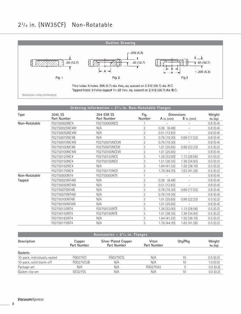
23⁄4 in. (NW35CF) Non-Rotatable
8
Dimensions: inches (millimeters)
Outline Drawing
Type 304L SS 304 ESR SS Fig. Dimensions WeightPart Number Part Number Number A in. (mm) B in. (mm) lbs (kg)
Non-Rotatable F02750000NC4 F02750000NCE 1 – – 0.8 (0.4)F02750025NC4W N/A 2 0.26 (6.48) – 0.8 (0.4)F02750050NC4W N/A 2 0.51 (12.83) – 0.8 (0.4)F02750075NC4B N/A 3 0.76 (19.30) 0.69 (17.53) 0.8 (0.4)F02750075NC4W F02750075NCEW 2 0.76 (19.30) – 0.8 (0.4)F02750100NC4B F02750075NCEB 3 1.01 (25.65) 0.88 (22.23) 0.5 (0.2)F02750100NC4W F02750100NCEW 2 1.01 (25.65) – 0.8 (0.4)F02750125NC4 F02750125NCE 3 1.26 (32.00) 1.13 (28.56) 0.5 (0.2)F02750150NC4 F02750150NCE 3 1.51 (38.35) 1.38 (34.93) 0.5 (0.2)F02750162NC4 N/A 3 1.64 (41.53) 1.50 (38.10) 0.5 (0.2)F02750175NC4 F02750175NCE 3 1.76 (44.70) 1.63 (41.28) 0.5 (0.2)
Non-Rotatable F02750000NT4 F02750000NTE 1 – – 0.8 (0.4)Tapped F02750025NT4W N/A 2 0.26 (6.48) – 0.8 (0.4)
F02750050NT4W N/A 2 0.51 (12.83) – 0.8 (0.4)F02750075NT4B N/A 3 0.76 (19.30) 0.69 (17.53) 0.8 (0.4)F02750075NT4W N/A 2 0.76 (19.30) – 0.8 (0.4)F02750100NT4B N/A 3 1.01 (25.65) 0.88 (22.23) 0.5 (0.2)F02750100NT4W N/A 2 1.01 (25.65) – 0.8 (0.4)F02750125NT4 F02750125NTE 3 1.26 (32.00) 1.13 (28.56) 0.5 (0.2)F02750150NT4 F02750150NTE 3 1.51 (38.35) 1.38 (34.93) 0.5 (0.2)F02750162NT4 N/A 3 1.64 (41.53) 1.50 (38.10) 0.5 (0.2)F02750175NT4 N/A 3 1.76 (44.70) 1.63 (41.28) 0.5 (0.2)
Ordering Information – 23⁄4 in. Non-Rotatable Flanges
Description Copper Silver Plated Copper Viton Qty/Pkg WeightPart Number Part Number Part Number lbs (kg)
Gaskets10-pack, individually sealed FG0275CI FG0275CIS N/A 10 0.5 (0.2)10-pack, solid blank-off FG0275CUB N/A N/A 10 1.0 (0.5)Package set N/A N/A FG0275VU 5 0.5 (0.2)Gasket clip set GC0275S N/A N/A 10 0.5 (0.2)
Accessories – 23⁄4 in. Flanges
ComponentsConFlat® F langes
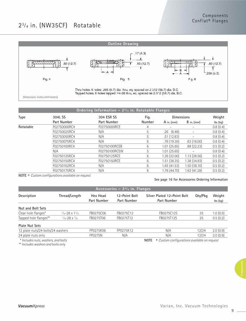
23⁄4 in. (NW35CF) Rotatable
9Varian, Inc. Vacuum Technologies
Com
pone
nts
Dimensions: inches (millimeters)
Outline Drawing
Type 304L SS 304 ESR SS Fig. Dimensions WeightPart Number Part Number Number A in. (mm) B in. (mm) lbs (kg)
Rotatable F02750000RC4 F02750000RCE 4 – – 0.8 (0.4)F02750025RC4 N/A 5 .26 (6.48) – 0.8 (0.4)F02750050RC4 N/A 5 .51 (12.83) – 0.8 (0.4)F02750075RC4 N/A 6 .76 (19.30) .63 (16.00) 0.8 (0.4)F02750100RC4 F02750100RCEB 6 1.01 (25.65) .88 (22.23) 0.5 (0.2)N/A F02750100RCEW 5 1.01 (25.65) – 0.8 (0.4)F02750125RC4 F02750125RCE 6 1.26 (32.00) 1.13 (28.56) 0.5 (0.2)F02750150RC4 F02750150RCE 6 1.51 (38.35) 1.38 (34.93) 0.5 (0.2)F02750162RC4 N/A 6 1.65 (41.53) 1.50 (38.10) 0.5 (0.2)F02750175RC4 N/A 6 1.76 (44.70) 1.63 (41.28) 0.5 (0.2)
NOTE • Custom configurations available on requestSee page 16 for Accessories Ordering Information
Ordering Information – 23⁄4 in. Rotatable Flanges
Description Thread/Length Hex Head 12-Point Bolt Silver Plated 12-Point Bolt Qty/Pkg WeightPart Number Part Number Part Number lbs (kg)
Nut and Bolt SetsClear hole flanges* 1⁄4-28 x 11⁄4 FB0275C06 FB0275C12 FB0275C12S 25 1.0 (0.5) Tapped hole flanges** 1⁄4-28 x 7⁄8 FB0275T06 FB0275T12 FB0275T12S 25 0.5 (0.2)
Plate Nut Sets12 plate nuts/24 bolts/24 washers FP0275K06 FP0275K12 N/A 12/24 2.0 (0.9) 24 plate nuts only FP0275N N/A N/A 12/24 2.0 (0.9)* Includes nuts, washers, and bolts NOTE • Custom configurations available on request
** Includes washers and bolts only
Accessories – 23⁄4 in. Flanges
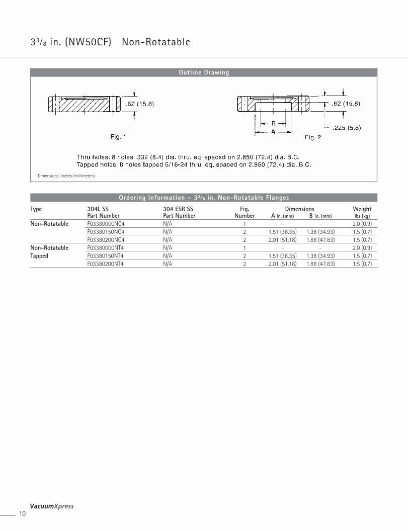
33⁄8 in. (NW50CF) Non-Rotatable
10
Dimensions: inches (millimeters)
Outline Drawing
Type 304L SS 304 ESR SS Fig. Dimensions WeightPart Number Part Number Number A in. (mm) B in. (mm) lbs (kg)
Non-Rotatable F03380000NC4 N/A 1 – – 2.0 (0.9)F03380150NC4 N/A 2 1.51 (38.35) 1.38 (34.93) 1.5 (0.7)F03380200NC4 N/A 2 2.01 (51.18) 1.88 (47.63) 1.5 (0.7)
Non-Rotatable F03380000NT4 N/A 1 – – 2.0 (0.9)Tapped F03380150NT4 N/A 2 1.51 (38.35) 1.38 (34.93) 1.5 (0.7)
F03380200NT4 N/A 2 2.01 (51.18) 1.88 (47.63) 1.5 (0.7)
Ordering Information – 33⁄8 in. Non-Rotatable Flanges
Dimensions: inches (millimeters)
Outline Drawing
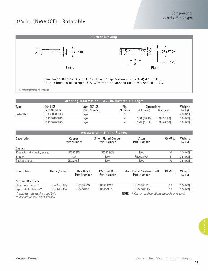
ComponentsConFlat® F langes
33⁄8 in. (NW50CF) Rotatable
11Varian, Inc. Vacuum Technologies
Com
pone
nts
Type 304L SS 304 ESR SS Fig. Dimensions WeightPart Number Part Number Number A in. (mm) B in. (mm) lbs (kg)
Rotatable F03380000RC4 N/A 3 – – 2.0 (0.9)F03380150RC4 N/A 4 1.51 (38.35) 1.38 (34.93) 1.5 (0.7)F03380200RC4 N/A 4 2.02 (51.18) 1.88 (47.63) 1.5 (0.7)
Ordering Information – 33⁄8 in. Rotatable Flanges
Description Copper Silver Plated Copper Viton Qty/Pkg WeightPart Number Part Number Part Number lbs (kg)
Gaskets10-pack, individually sealed FG0338CI FG0338CIS N/A 10 1.0 (0.5)1-pack N/A N/A FG0338VU 1 0.5 (0.2)Gasket clip set GC0275S N/A N/A 10 0.5 (0.2)
Description Thread/Length Hex Head 12-Point Bolt Silver Plated 12-Point Bolt Qty/Pkg WeightPart Number Part Number Part Number lbs (kg)
Nut and Bolt SetsClear hole flanges* 5⁄16-24 x 13⁄4 FB0338C06 FB0338C12 FB0338C12S 25 2.0 (0.9) Tapped hole flanges** 5⁄16-24 x 11⁄4 FB0450T06 FB0450T12 FB0450T12S 25 2.0 (0.9)* Includes nuts, washers, and bolts NOTE • Custom configurations available on request
** Includes washers and bolts only
Accessories – 33⁄8 in. Flanges
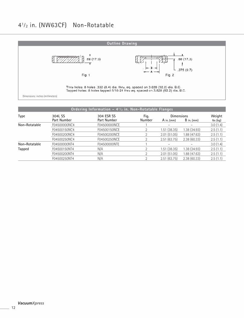
41⁄2 in. (NW63CF) Non-Rotatable
12
Dimensions: inches (millimeters)
Outline Drawing
Type 304L SS 304 ESR SS Fig. Dimensions WeightPart Number Part Number Number A in. (mm) B in. (mm) lbs (kg)
Non-Rotatable F04500000NC4 F04500000NCE 1 – – 3.0 (1.4)F04500150NC4 F04500150NCE 2 1.51 (38.35) 1.38 (34.93) 2.5 (1.1)F04500200NC4 F04500200NCE 2 2.01 (51.05) 1.88 (47.63) 2.5 (1.1)F04500250NC4 F04500250NCE 2 2.51 (63.75) 2.38 (60.33) 2.5 (1.1)
Non-Rotatable F04500000NT4 F04500000NTE 1 – – 3.0 (1.4)Tapped F04500150NT4 N/A 2 1.51 (38.35) 1.38 (34.93) 2.5 (1.1)
F04500200NT4 N/A 2 2.01 (51.05) 1.88 (47.63) 2.5 (1.1)F04500250NT4 N/A 2 2.51 (63.75) 2.38 (60.33) 2.5 (1.1)
Ordering Information – 41⁄2 in. Non-Rotatable Flanges
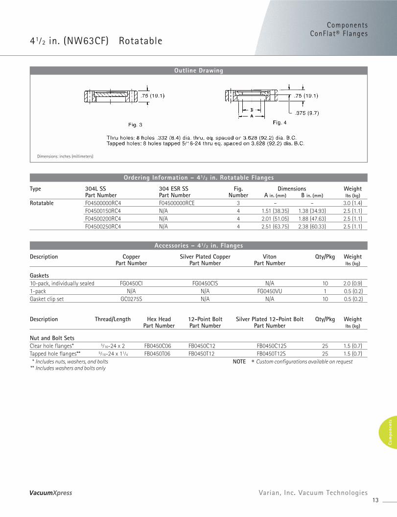
ComponentsConFlat® F langes
41⁄2 in. (NW63CF) Rotatable
13Varian, Inc. Vacuum Technologies
Com
pone
nts
Dimensions: inches (millimeters)
Outline Drawing
Type 304L SS 304 ESR SS Fig. Dimensions WeightPart Number Part Number Number A in. (mm) B in. (mm) lbs (kg)
Rotatable F04500000RC4 F04500000RCE 3 – – 3.0 (1.4)F04500150RC4 N/A 4 1.51 (38.35) 1.38 (34.93) 2.5 (1.1)F04500200RC4 N/A 4 2.01 (51.05) 1.88 (47.63) 2.5 (1.1)F04500250RC4 N/A 4 2.51 (63.75) 2.38 (60.33) 2.5 (1.1)
Ordering Information – 41⁄2 in. Rotatable Flanges
Description Copper Silver Plated Copper Viton Qty/Pkg WeightPart Number Part Number Part Number lbs (kg)
Gaskets10-pack, individually sealed FG0450CI FG0450CIS N/A 10 2.0 (0.9)1-pack N/A N/A FG0450VU 1 0.5 (0.2)Gasket clip set GC0275S N/A N/A 10 0.5 (0.2)
Description Thread/Length Hex Head 12-Point Bolt Silver Plated 12-Point Bolt Qty/Pkg WeightPart Number Part Number Part Number lbs (kg)
Nut and Bolt SetsClear hole flanges* 5⁄16-24 x 2 FB0450C06 FB0450C12 FB0450C12S 25 1.5 (0.7) Tapped hole flanges** 5⁄16-24 x 11⁄4 FB0450T06 FB0450T12 FB0450T12S 25 1.5 (0.7)* Includes nuts, washers, and bolts NOTE • Custom configurations available on request
** Includes washers and bolts only
Accessories – 41⁄2 in. Flanges
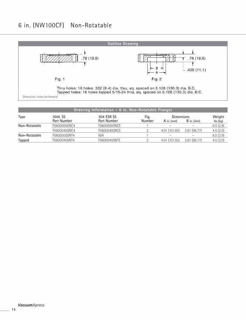
6 in. (NW100CF) Non-Rotatable
14
Dimensions: inches (millimeters)
Outline Drawing
Type 304L SS 304 ESR SS Fig. Dimensions WeightPart Number Part Number Number A in. (mm) B in. (mm) lbs (kg)
Non-Rotatable F06000000NC4 F06000000NCE 1 – – 6.5 (2.9)F06000400NC4 F06000400NCE 2 4.01 (101.85) 3.81 (96.77) 4.5 (2.0)
Non-Rotatable F06000000NT4 N/A 1 – – 6.5 (2.9)Tapped F06000400NT4 F06000400NTE 2 4.01 (101.85) 3.81 (96.77) 4.5 (2.0)
Ordering Information – 6 in. Non-Rotatable Flanges
ComponentsConFlat® F langes
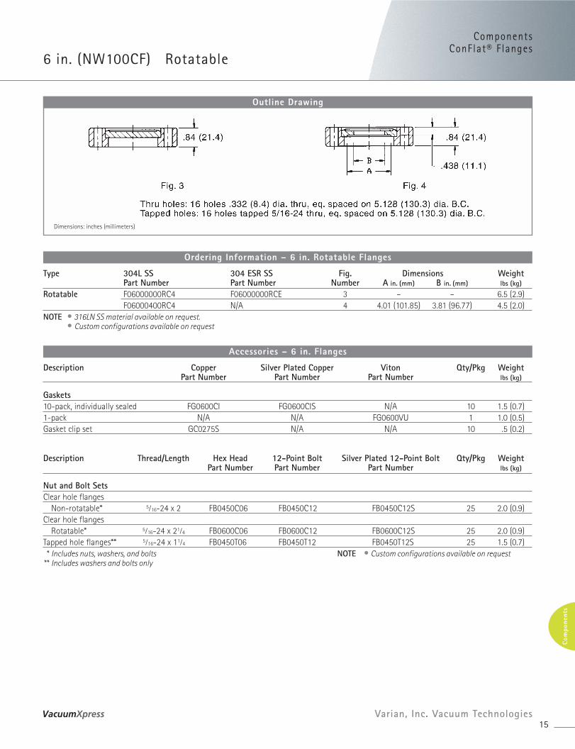
6 in. (NW100CF) Rotatable
15Varian, Inc. Vacuum Technologies
Com
pone
nts
Dimensions: inches (millimeters)
Outline Drawing
Type 304L SS 304 ESR SS Fig. Dimensions WeightPart Number Part Number Number A in. (mm) B in. (mm) lbs (kg)
Rotatable F06000000RC4 F06000000RCE 3 – – 6.5 (2.9)F06000400RC4 N/A 4 4.01 (101.85) 3.81 (96.77) 4.5 (2.0)
NOTE • 316LN SS material available on request.• Custom configurations available on request
Ordering Information – 6 in. Rotatable Flanges
Description Copper Silver Plated Copper Viton Qty/Pkg WeightPart Number Part Number Part Number lbs (kg)
Gaskets10-pack, individually sealed FG0600CI FG0600CIS N/A 10 1.5 (0.7)1-pack N/A N/A FG0600VU 1 1.0 (0.5)Gasket clip set GC0275S N/A N/A 10 .5 (0.2)
Description Thread/Length Hex Head 12-Point Bolt Silver Plated 12-Point Bolt Qty/Pkg WeightPart Number Part Number Part Number lbs (kg)
Nut and Bolt SetsClear hole flanges
Non-rotatable* 5⁄16-24 x 2 FB0450C06 FB0450C12 FB0450C12S 25 2.0 (0.9)Clear hole flanges
Rotatable* 5⁄16-24 x 21⁄4 FB0600C06 FB0600C12 FB0600C12S 25 2.0 (0.9) Tapped hole flanges** 5⁄16-24 x 11⁄4 FB0450T06 FB0450T12 FB0450T12S 25 1.5 (0.7)* Includes nuts, washers, and bolts NOTE • Custom configurations available on request
** Includes washers and bolts only
Accessories – 6 in. Flanges
16
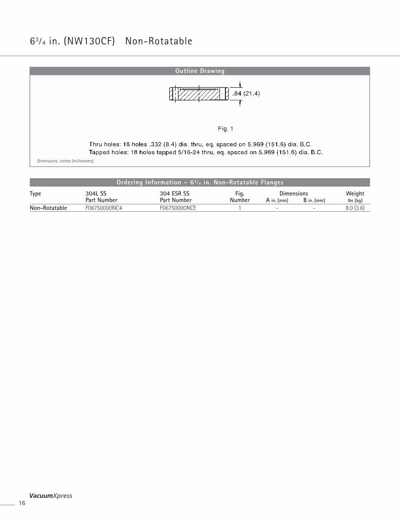
63⁄4 in. (NW130CF) Non-Rotatable
Dimensions: inches (millimeters)
Outline Drawing
Type 304L SS 304 ESR SS Fig. Dimensions WeightPart Number Part Number Number A in. (mm) B in. (mm) lbs (kg)
Non-Rotatable F06750000NC4 F06750000NCE 1 – – 8.0 (3.6)
Ordering Information – 63⁄4 in. Non-Rotatable Flanges
ComponentsConFlat® F langes
17Varian, Inc. Vacuum Technologies
Com
pone
nts
Description Copper Silver Plated Copper Viton Qty/Pkg WeightPart Number Part Number Part Number lbs (kg)
Gaskets10-Pack, individually sealed FG0675CI FG0675CIS N/A 10 2.0 (0.9)1-pack N/A N/A FG0675VU 1 1.0 (0.5)Gasket clip set GC0275S N/A N/A 10 0.5 (0.2)
Description Thread/Length Hex Head 12-Point Bolt Silver Plated 12-Point Bolt Qty/Pkg WeightPart Number Part Number Part Number lbs (kg)
Nut and Bolt SetsClear hole flanges* 5⁄16-24 x 21⁄4 FB0600C06 FB0600C12 FB0600C12S 25 2.0 (0.9)Tapped hole flanges** 5⁄16-24 x 13⁄4 FB0800T06 FB0800T12 FB0800T12S 25 2.0 (0.9)* Includes nuts, washers, and bolts NOTE • Custom configurations available on request
** Includes washers and bolts only
Accessories – 63⁄4 in. Flanges
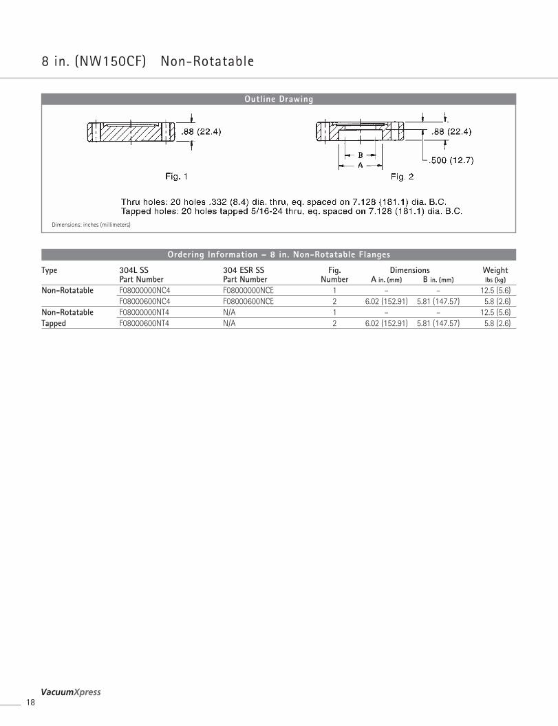
8 in. (NW150CF) Non-Rotatable
18
Dimensions: inches (millimeters)
Outline Drawing
Type 304L SS 304 ESR SS Fig. Dimensions WeightPart Number Part Number Number A in. (mm) B in. (mm) lbs (kg)
Non-Rotatable F08000000NC4 F08000000NCE 1 – – 12.5 (5.6)F08000600NC4 F08000600NCE 2 6.02 (152.91) 5.81 (147.57) 5.8 (2.6)
Non-Rotatable F08000000NT4 N/A 1 – – 12.5 (5.6)Tapped F08000600NT4 N/A 2 6.02 (152.91) 5.81 (147.57) 5.8 (2.6)
Ordering Information – 8 in. Non-Rotatable Flanges
ComponentsConFlat® F langes
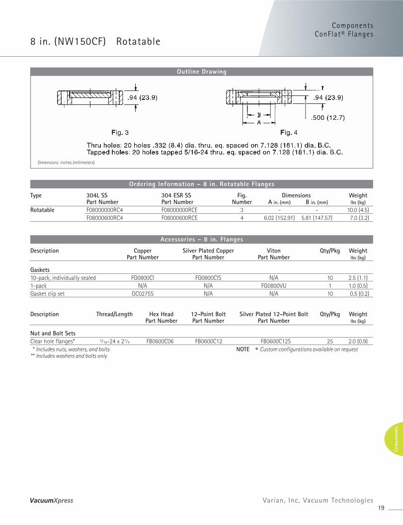
8 in. (NW150CF) Rotatable
19Varian, Inc. Vacuum Technologies
Com
pone
nts
Dimensions: inches (millimeters)
Outline Drawing
Type 304L SS 304 ESR SS Fig. Dimensions WeightPart Number Part Number Number A in. (mm) B in. (mm) lbs (kg)
Rotatable F08000000RC4 F08000000RCE 3 – – 10.0 (4.5)F08000600RC4 F08000600RCE 4 6.02 (152.91) 5.81 (147.57) 7.0 (3.2)
Ordering Information – 8 in. Rotatable Flanges
Description Copper Silver Plated Copper Viton Qty/Pkg WeightPart Number Part Number Part Number lbs (kg)
Gaskets10-pack, individually sealed FG0800CI FG0800CIS N/A 10 2.5 (1.1)1-pack N/A N/A FG0800VU 1 1.0 (0.5)Gasket clip set GC0275S N/A N/A 10 0.5 (0.2)
Description Thread/Length Hex Head 12-Point Bolt Silver Plated 12-Point Bolt Qty/Pkg WeightPart Number Part Number Part Number lbs (kg)
Nut and Bolt SetsClear hole flanges* 5⁄16-24 x 21⁄4 FB0600C06 FB0600C12 FB0600C12S 25 2.0 (0.9)* Includes nuts, washers, and bolts NOTE • Custom configurations available on request
** Includes washers and bolts only
Accessories – 8 in. Flanges

10 in. (NW200CF) Non-Rotatable
20
Dimensions: inches (millimeters)
Outline Drawing
Type 304L SS 304 ESR SS Fig. Dimensions WeightPart Number Part Number Number A in. (mm) B in. (mm) lbs (kg)
Non-Rotatable F10000000NC4 F10000000NCE 1 – – 21.0 (9.5)F10000800NC4 F10000800NCE 2 8.04 (204.22) 7.81 (198.37) 8.0 (3.6)
Non-Rotatable F10000000NT4 N/A 1 – – 21.0 (9.5)Tapped F10000800NT4 N/A 2 8.04 (204.22) 7.81 (198.37) 8.0 (3.6)
Ordering Information – 10 in. Non-Rotatable Flanges
ComponentsConFlat® F langes
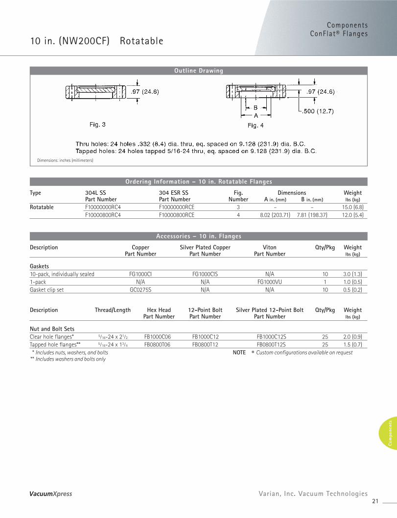
10 in. (NW200CF) Rotatable
21Varian, Inc. Vacuum Technologies
Com
pone
nts
Dimensions: inches (millimeters)
Outline Drawing
Type 304L SS 304 ESR SS Fig. Dimensions WeightPart Number Part Number Number A in. (mm) B in. (mm) lbs (kg)
Rotatable F10000000RC4 F10000000RCE 3 – – 15.0 (6.8)F10000800RC4 F10000800RCE 4 8.02 (203.71) 7.81 (198.37) 12.0 (5.4)
Ordering Information – 10 in. Rotatable Flanges
Description Copper Silver Plated Copper Viton Qty/Pkg WeightPart Number Part Number Part Number lbs (kg)
Gaskets10-pack, individually sealed FG1000CI FG1000CIS N/A 10 3.0 (1.3)1-pack N/A N/A FG1000VU 1 1.0 (0.5)Gasket clip set GC0275S N/A N/A 10 0.5 (0.2)
Description Thread/Length Hex Head 12-Point Bolt Silver Plated 12-Point Bolt Qty/Pkg WeightPart Number Part Number Part Number lbs (kg)
Nut and Bolt SetsClear hole flanges* 5⁄16-24 x 21⁄2 FB1000C06 FB1000C12 FB1000C12S 25 2.0 (0.9)Tapped hole flanges** 5⁄16-24 x 13⁄4 FB0800T06 FB0800T12 FB0800T12S 25 1.5 (0.7)* Includes nuts, washers, and bolts NOTE • Custom configurations available on request
** Includes washers and bolts only
Accessories – 10 in. Flanges
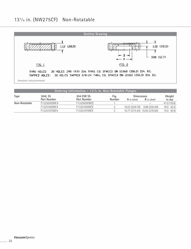
131⁄4 in. (NW275CF) Non-Rotatable
22
Dimensions: inches (millimeters)
Outline Drawing
Type 304L SS 304 ESR SS Fig. Dimensions WeightPart Number Part Number Number A in. (mm) B in. (mm) lbs (kg)
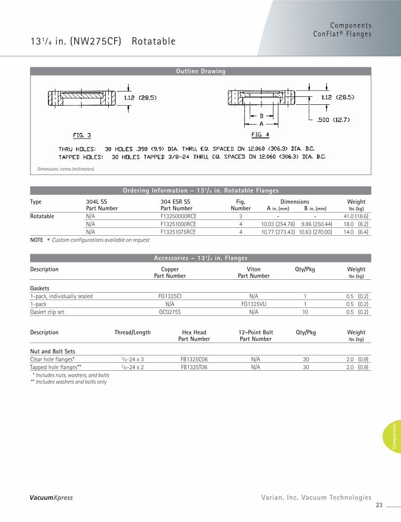
Non-Rotatable F13250000NC4 F13250000NCE 1 – – 41.0 (18.6)F13251000NC4 F13251000NCE 2 10.03 (254.76) 9.86 (250.44) 18.0 (8.2)F13251075NC4 F13251075NCE 2 10.77 (273.43) 10.63 (270.00) 14.0 (6.4)
Ordering Information – 131/4 in. Non-Rotatable Flanges
ComponentsConFlat® F langes
131⁄4 in. (NW275CF) Rotatable
23Varian, Inc. Vacuum Technologies
Com
pone
nts
Dimensions: inches (millimeters)
Outline Drawing
Type 304L SS 304 ESR SS Fig. Dimensions WeightPart Number Part Number Number A in. (mm) B in. (mm) lbs (kg)
Rotatable N/A F13250000RCE 3 – – 41.0 (18.6)N/A F13251000RCE 4 10.03 (254.76) 9.86 (250.44) 18.0 (8.2)N/A F13251075RCE 4 10.77 (273.43) 10.63 (270.00) 14.0 (6.4)
NOTE • Custom configurations available on request
Ordering Information – 131/4 in. Rotatable Flanges
Description Copper Viton Qty/Pkg WeightPart Number Part Number lbs (kg)
Gaskets1-pack, individually sealed FG1325CI N/A 1 0.5 (0.2)1-pack N/A FG1325VU 1 0.5 (0.2)Gasket clip set GC0275S N/A 10 0.5 (0.2)
Description Thread/Length Hex Head 12-Point Bolt Qty/Pkg WeightPart Number Part Number lbs (kg)
Nut and Bolt SetsClear hole flanges* 3⁄8-24 x 3 FB1325C06 N/A 30 2.0 (0.9) Tapped hole flanges** 3⁄8-24 x 2 FB1325T06 N/A 30 2.0 (0.9)* Includes nuts, washers, and bolts
** Includes washers and bolts only
Accessories – 131/4 in. Flanges
23⁄4 in. – 10 in. Reducing
24
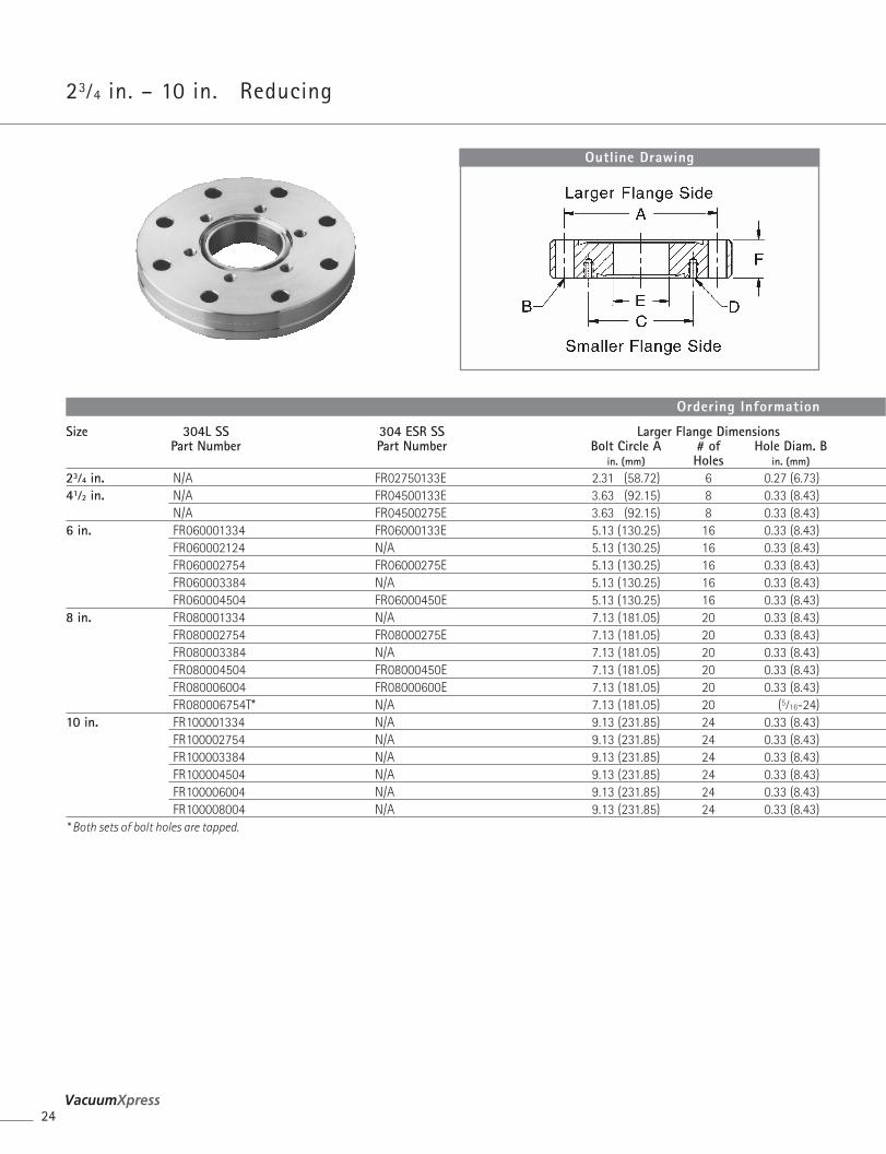
Outline Drawing
Size 304L SS 304 ESR SS Larger Flange DimensionsPart Number Part Number Bolt Circle A # of Hole Diam. B
in. (mm) Holes in. (mm)
23⁄4 in. N/A FR02750133E 2.31 (58.72) 6 0.27 (6.73)41⁄2 in. N/A FR04500133E 3.63 (92.15) 8 0.33 (8.43)
N/A FR04500275E 3.63 (92.15) 8 0.33 (8.43)6 in. FR060001334 FR06000133E 5.13 (130.25) 16 0.33 (8.43)
FR060002124 N/A 5.13 (130.25) 16 0.33 (8.43)FR060002754 FR06000275E 5.13 (130.25) 16 0.33 (8.43)FR060003384 N/A 5.13 (130.25) 16 0.33 (8.43)FR060004504 FR06000450E 5.13 (130.25) 16 0.33 (8.43)
8 in. FR080001334 N/A 7.13 (181.05) 20 0.33 (8.43)FR080002754 FR08000275E 7.13 (181.05) 20 0.33 (8.43)FR080003384 N/A 7.13 (181.05) 20 0.33 (8.43)FR080004504 FR08000450E 7.13 (181.05) 20 0.33 (8.43)FR080006004 FR08000600E 7.13 (181.05) 20 0.33 (8.43)FR080006754T* N/A 7.13 (181.05) 20 (5⁄16-24)
10 in. FR100001334 N/A 9.13 (231.85) 24 0.33 (8.43)FR100002754 N/A 9.13 (231.85) 24 0.33 (8.43)FR100003384 N/A 9.13 (231.85) 24 0.33 (8.43)FR100004504 N/A 9.13 (231.85) 24 0.33 (8.43)FR100006004 N/A 9.13 (231.85) 24 0.33 (8.43)FR100008004 N/A 9.13 (231.85) 24 0.33 (8.43)
* Both sets of bolt holes are tapped.
Ordering Information
ComponentsConFlat® F langes
25Varian, Inc. Vacuum Technologies
Com
pone
nts
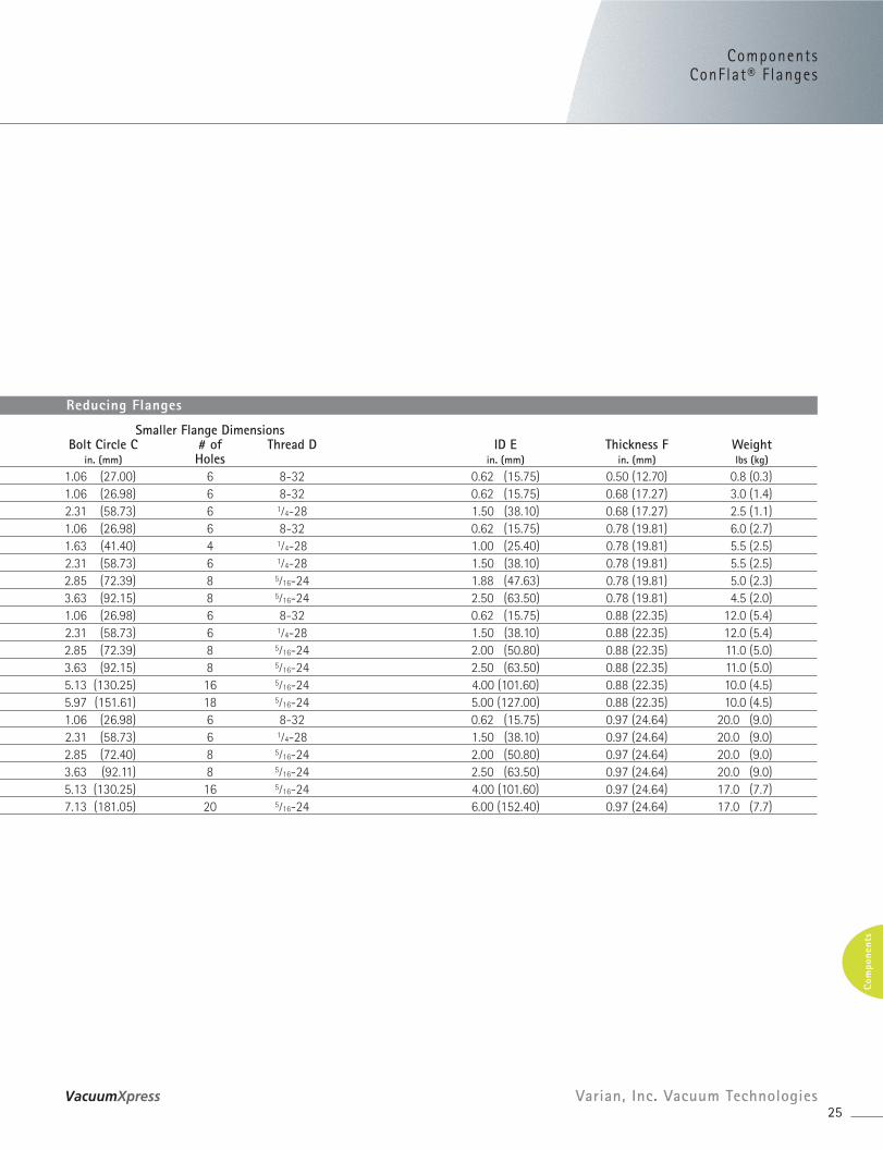
Smaller Flange DimensionsBolt Circle C # of Thread D ID E Thickness F Weight
in. (mm) Holes in. (mm) in. (mm) lbs (kg)
1.06 (27.00) 6 8-32 0.62 (15.75) 0.50 (12.70) 0.8 (0.3)1.06 (26.98) 6 8-32 0.62 (15.75) 0.68 (17.27) 3.0 (1.4)2.31 (58.73) 6 1⁄4-28 1.50 (38.10) 0.68 (17.27) 2.5 (1.1)1.06 (26.98) 6 8-32 0.62 (15.75) 0.78 (19.81) 6.0 (2.7)1.63 (41.40) 4 1⁄4-28 1.00 (25.40) 0.78 (19.81) 5.5 (2.5)2.31 (58.73) 6 1⁄4-28 1.50 (38.10) 0.78 (19.81) 5.5 (2.5)2.85 (72.39) 8 5⁄16-24 1.88 (47.63) 0.78 (19.81) 5.0 (2.3)3.63 (92.15) 8 5⁄16-24 2.50 (63.50) 0.78 (19.81) 4.5 (2.0)1.06 (26.98) 6 8-32 0.62 (15.75) 0.88 (22.35) 12.0 (5.4)2.31 (58.73) 6 1⁄4-28 1.50 (38.10) 0.88 (22.35) 12.0 (5.4)2.85 (72.39) 8 5⁄16-24 2.00 (50.80) 0.88 (22.35) 11.0 (5.0)3.63 (92.15) 8 5⁄16-24 2.50 (63.50) 0.88 (22.35) 11.0 (5.0)5.13 (130.25) 16 5⁄16-24 4.00 (101.60) 0.88 (22.35) 10.0 (4.5)5.97 (151.61) 18 5⁄16-24 5.00 (127.00) 0.88 (22.35) 10.0 (4.5)1.06 (26.98) 6 8-32 0.62 (15.75) 0.97 (24.64) 20.0 (9.0)2.31 (58.73) 6 1⁄4-28 1.50 (38.10) 0.97 (24.64) 20.0 (9.0)2.85 (72.40) 8 5⁄16-24 2.00 (50.80) 0.97 (24.64) 20.0 (9.0)3.63 (92.11) 8 5⁄16-24 2.50 (63.50) 0.97 (24.64) 20.0 (9.0)5.13 (130.25) 16 5⁄16-24 4.00 (101.60) 0.97 (24.64) 17.0 (7.7)7.13 (181.05) 20 5⁄16-24 6.00 (152.40) 0.97 (24.64) 17.0 (7.7)
Reducing Flanges
Accessories
26
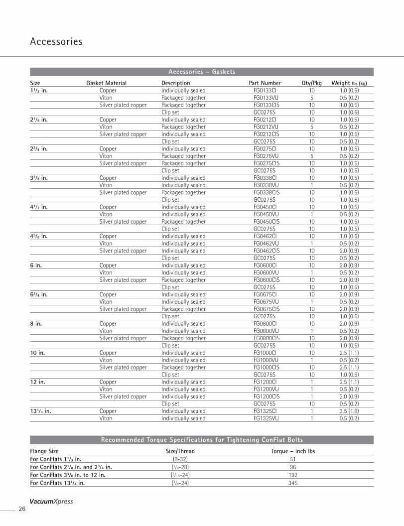
Size Gasket Material Description Part Number Qty/Pkg Weight lbs (kg)11⁄3 in. Copper Individually sealed FG0133CI 10 1.0 (0.5)
Viton Packaged together FG0133VU 5 0.5 (0.2)Silver plated copper Packaged together FG0133CIS 10 1.0 (0.5)
Clip set GC0275S 10 1.0 (0.5)21⁄8 in. Copper Individually sealed FG0212CI 10 1.0 (0.5)
Viton Packaged together FG0212VU 5 0.5 (0.2)Silver plated copper Individually sealed FG0212CIS 10 1.0 (0.5)
Clip set GC0275S 10 0.5 (0.2)23⁄4 in. Copper Individually sealed FG0275CI 10 1.0 (0.5)
Viton Packaged together FG0275VU 5 0.5 (0.2)Silver plated copper Packaged together FG0275CIS 10 1.0 (0.5)
Clip set GC0275S 10 1.0 (0.5)33⁄8 in. Copper Individually sealed FG0338CI 10 1.0 (0.5)
Viton Individually sealed FG0338VU 1 0.5 (0.2)Silver plated copper Packaged together FG0338CIS 10 1.0 (0.5)
Clip set GC0275S 10 1.0 (0.5)41⁄2 in. Copper Individually sealed FG0450CI 10 1.0 (0.5)
Viton Individually sealed FG0450VU 1 0.5 (0.2)Silver plated copper Packaged together FG0450CIS 10 1.0 (0.5)
Clip set GC0275S 10 1.0 (0.5)45⁄8 in. Copper Individually sealed FG0462CI 10 1.0 (0.5)
Viton Individually sealed FG0462VU 1 0.5 (0.2)Silver plated copper Individually sealed FG0462CIS 10 2.0 (0.9)
Clip set GC0275S 10 0.5 (0.2)6 in. Copper Individually sealed FG0600CI 10 2.0 (0.9)
Viton Individually sealed FG0600VU 1 0.5 (0.2)Silver plated copper Packaged together FG0600CIS 10 2.0 (0.9)
Clip set GC0275S 10 1.0 (0.5)63⁄4 in. Copper Individually sealed FG0675CI 10 2.0 (0.9)
Viton Individually sealed FG0675VU 1 0.5 (0.2)Silver plated copper Packaged together FG0675CIS 10 2.0 (0.9)
Clip set GC0275S 10 1.0 (0.5)8 in. Copper Individually sealed FG0800CI 10 2.0 (0.9)
Viton Individually sealed FG0800VU 1 0.5 (0.2)Silver plated copper Packaged together FG0800CIS 10 2.0 (0.9)
Clip set GC0275S 10 1.0 (0.5)10 in. Copper Individually sealed FG1000CI 10 2.5 (1.1)
Viton Individually sealed FG1000VU 1 0.5 (0.2)Silver plated copper Packaged together FG1000CIS 10 2.5 (1.1)
Clip set GC0275S 10 1.0 (0.5)12 in. Copper Individually sealed FG1200CI 1 2.5 (1.1)
Viton Individually sealed FG1200VU 1 0.5 (0.2)Silver plated copper Individually sealed FG1200CIS 1 2.0 (0.9)
Clip set GC0275S 10 0.5 (0.2)131⁄4 in. Copper Individually sealed FG1325CI 1 3.5 (1.6)
Viton Individually sealed FG1325VU 1 0.5 (0.2)
Accessories – Gaskets
Flange Size Size/Thread Torque – inch lbsFor ConFlats 11⁄3 in. (8-32) 51For ConFlats 21⁄8 in. and 23⁄4 in. (1⁄4-28) 96For ConFlats 33⁄8 in. to 12 in. (5⁄16-24) 192For ConFlats 131⁄4 in. (3⁄8-24) 345
Recommended Torque Specifications for Tightening ConFlat Bolts
ComponentsConFlat® F langes
27Varian, Inc. Vacuum Technologies
Com
pone
nts
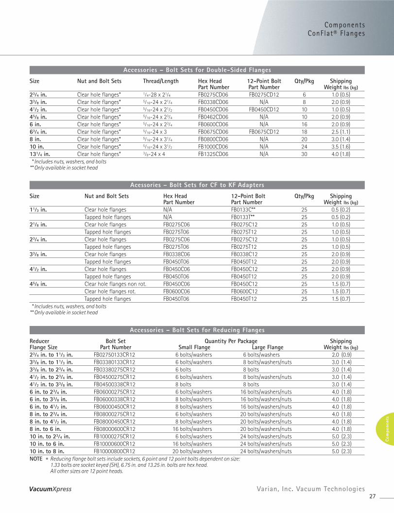
Size Nut and Bolt Sets Thread/Length Hex Head 12-Point Bolt Qty/Pkg ShippingPart Number Part Number Weight lbs (kg)
23⁄4 in. Clear hole flanges* 1⁄4-28 x 21⁄4 FB0275CD06 FB0275CD12 6 1.0 (0.5)33⁄8 in. Clear hole flanges* 5⁄16-24 x 21⁄4 FB0338CD06 N/A 8 2.0 (0.9)41⁄2 in. Clear hole flanges* 5⁄16-24 x 21⁄2 FB0450CD06 FB0450CD12 10 1.0 (0.5)45⁄8 in. Clear hole flanges* 5⁄16-24 x 23⁄4 FB0462CD06 N/A 10 2.0 (0.9)6 in. Clear hole flanges* 5⁄16-24 x 23⁄4 FB0600CD06 N/A 16 2.0 (0.9)63⁄4 in. Clear hole flanges* 5⁄16-24 x 3 FB0675CD06 FB0675CD12 18 2.5 (1.1)8 in. Clear hole flanges* 5⁄16-24 x 31⁄4 FB0800CD06 N/A 20 3.0 (1.4)10 in. Clear hole flanges* 5⁄16-24 x 31⁄2 FB1000CD06 N/A 24 3.5 (1.6)131⁄4 in. Clear hole flanges* 3⁄8-24 x 4 FB1325CD06 N/A 30 4.0 (1.8)* Includes nuts, washers, and bolts
** Only available in socket head
Accessories – Bolt Sets for Double-Sided Flanges
Size Nut and Bolt Sets Hex Head 12-Point Bolt Qty/Pkg ShippingPart Number Part Number Weight lbs (kg)
11⁄3 in. Clear hole flanges N/A FB0133C** 25 0.5 (0.2)Tapped hole flanges N/A FB0133T** 25 0.5 (0.2)
21⁄8 in. Clear hole flanges FB0275C06 FB0275C12 25 1.0 (0.5)Tapped hole flanges FB0275T06 FB0275T12 25 1.0 (0.5)
23⁄4 in. Clear hole flanges FB0275C06 FB0275C12 25 1.0 (0.5)Tapped hole flanges FB0275T06 FB0275T12 25 1.0 (0.5)
33⁄8 in. Clear hole flanges FB0338C06 FB0338C12 25 2.0 (0.9)Tapped hole flanges FB0450T06 FB0450T12 25 2.0 (0.9)
41⁄2 in. Clear hole flanges FB0450C06 FB0450C12 25 2.0 (0.9)Tapped hole flanges FB0450T06 FB0450T12 25 2.0 (0.9)
45⁄8 in. Clear hole flanges non rot. FB0450C06 FB0450C12 25 1.5 (0.7)Clear hole flanges rot. FB0600C06 FB0600C12 25 1.5 (0.7)Tapped hole flanges FB0450T06 FB0450T12 25 1.5 (0.7)
* Includes nuts, washers, and bolts** Only available in socket head
Acessories – Bolt Sets for CF to KF Adapters
Reducer Bolt Set Quantity Per Package ShippingFlange Size Part Number Small Flange Large Flange Weight lbs (kg)23⁄4 in. to 11⁄3 in. FB02750133CR12 6 bolts/washers 6 bolts/washers 2.0 (0.9)33⁄8 in. to 11⁄3 in. FB03380133CR12 6 bolts/washers 8 bolts/washers/nuts 3.0 (1.4)33⁄8 in. to 23⁄4 in. FB03380275CR12 6 bolts 8 bolts 3.0 (1.4)41⁄2 in. to 23⁄4 in. FB04500275CR12 6 bolts/washers 8 bolts/washers/nuts 3.0 (1.4)41⁄2 in. to 33⁄8 in. FB04500338CR12 8 bolts 8 bolts 3.0 (1.4)6 in. to 23⁄4 in. FB06000275CR12 6 bolts/washers 16 bolts/washers/nuts 4.0 (1.8)6 in. to 33⁄8 in. FB06000338CR12 8 bolts/washers 16 bolts/washers/nuts 4.0 (1.8)6 in. to 41⁄2 in. FB06000450CR12 8 bolts/washers 16 bolts/washers/nuts 4.0 (1.8)8 in. to 23⁄4 in. FB08000275CR12 6 bolts/washers 20 bolts/washers/nuts 4.0 (1.8)8 in. to 41⁄2 in. FB08000450CR12 8 bolts/washers 20 bolts/washers/nuts 4.0 (1.8)8 in. to 6 in. FB08000600CR12 16 bolts/washers 20 bolts/washers/nuts 4.0 (1.8)10 in. to 23⁄4 in. FB10000275CR12 6 bolts/washers 24 bolts/washers/nuts 5.0 (2.3)10 in. to 6 in. FB10000600CR12 16 bolts/washers 24 bolts/washers/nuts 5.0 (2.3)10 in. to 8 in. FB10000800CR12 20 bolts/washers 24 bolts/washers/nuts 5.0 (2.3)NOTE • Reducing flange bolt sets include sockets, 6 point and 12 point bolts dependent on size:
1.33 bolts are socket keyed (SH), 6.75 in. and 13.25 in. bolts are hex head. All other sizes are 12 point heads.
Accessories – Bolt Sets for Reducing Flanges
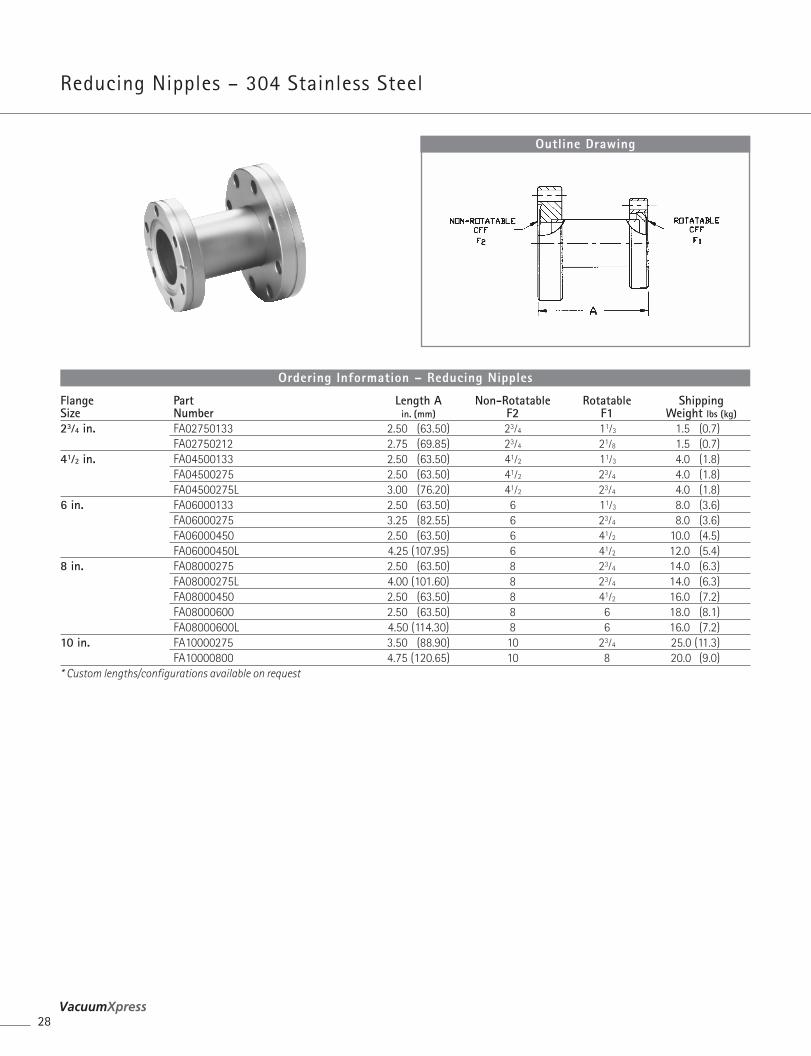
Reducing Nipples – 304 Stainless Steel
28
Flange Part Length A Non-Rotatable Rotatable ShippingSize Number in. (mm) F2 F1 Weight lbs (kg)23⁄4 in. FA02750133 2.50 (63.50) 23⁄4 11⁄3 1.5 (0.7)
FA02750212 2.75 (69.85) 23⁄4 21⁄8 1.5 (0.7)41⁄2 in. FA04500133 2.50 (63.50) 41⁄2 11⁄3 4.0 (1.8)
FA04500275 2.50 (63.50) 41⁄2 23⁄4 4.0 (1.8)FA04500275L 3.00 (76.20) 41⁄2 23⁄4 4.0 (1.8)
6 in. FA06000133 2.50 (63.50) 6 11⁄3 8.0 (3.6)FA06000275 3.25 (82.55) 6 23⁄4 8.0 (3.6)FA06000450 2.50 (63.50) 6 41⁄2 10.0 (4.5)FA06000450L 4.25 (107.95) 6 41⁄2 12.0 (5.4)
8 in. FA08000275 2.50 (63.50) 8 23⁄4 14.0 (6.3)FA08000275L 4.00 (101.60) 8 23⁄4 14.0 (6.3)FA08000450 2.50 (63.50) 8 41⁄2 16.0 (7.2)FA08000600 2.50 (63.50) 8 6 18.0 (8.1)FA08000600L 4.50 (114.30) 8 6 16.0 (7.2)
10 in. FA10000275 3.50 (88.90) 10 23⁄4 25.0 (11.3)FA10000800 4.75 (120.65) 10 8 20.0 (9.0)
* Custom lengths/configurations available on request
Ordering Information – Reducing Nipples
Outline Drawing
ComponentsConFlat® F i t t ings
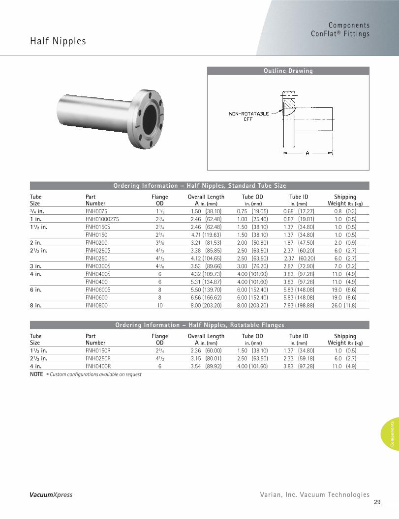
Half Nipples
29Varian, Inc. Vacuum Technologies
Com
pone
nts
Tube Part Flange Overall Length Tube OD Tube ID ShippingSize Number OD A in. (mm) in. (mm) in. (mm) Weight lbs (kg)3⁄4 in. FNH0075 11⁄3 1.50 (38.10) 0.75 (19.05) 0.68 (17.27) 0.8 (0.3)1 in. FNH01000275 23⁄4 2.46 (62.48) 1.00 (25.40) 0.87 (19.81) 1.0 (0.5)11⁄2 in. FNH0150S 23⁄4 2.46 (62.48) 1.50 (38.10) 1.37 (34.80) 1.0 (0.5)
FNH0150 23⁄4 4.71 (119.63) 1.50 (38.10) 1.37 (34.80) 1.0 (0.5)2 in. FNH0200 33⁄8 3.21 (81.53) 2.00 (50.80) 1.87 (47.50) 2.0 (0.9)21⁄2 in. FNH0250S 41⁄2 3.38 (85.85) 2.50 (63.50) 2.37 (60.20) 6.0 (2.7)
FNH0250 41⁄2 4.12 (104.65) 2.50 (63.50) 2.37 (60.20) 6.0 (2.7)3 in. FNH0300S 45⁄8 3.53 (89.66) 3.00 (76.20) 2.87 (72.90) 7.0 (3.2)4 in. FNH0400S 6 4.32 (109.73) 4.00 (101.60) 3.83 (97.28) 11.0 (4.9)
FNH0400 6 5.31 (134.87) 4.00 (101.60) 3.83 (97.28) 11.0 (4.9)6 in. FNH0600S 8 5.50 (139.70) 6.00 (152.40) 5.83 (148.08) 19.0 (8.6)
FNH0600 8 6.56 (166.62) 6.00 (152.40) 5.83 (148.08) 19.0 (8.6)8 in. FNH0800 10 8.00 (203.20) 8.00 (203.20) 7.83 (198.88) 26.0 (11.8)
Ordering Information – Half Nipples, Standard Tube Size
Tube Part Flange Overall Length Tube OD Tube ID ShippingSize Number OD A in. (mm) in. (mm) in. (mm) Weight lbs (kg)
11⁄2 in. FNH0150R 23⁄4 2.36 (60.00) 1.50 (38.10) 1.37 (34.80) 1.0 (0.5)21⁄2 in. FNH0250R 41⁄2 3.15 (80.01) 2.50 (63.50) 2.33 (59.18) 6.0 (2.7)4 in. FNH0400R 6 3.54 (89.92) 4.00 (101.60) 3.83 (97.28) 11.0 (4.9)NOTE • Custom configurations available on request
Ordering Information – Half Nipples, Rotatable Flanges
Outline Drawing
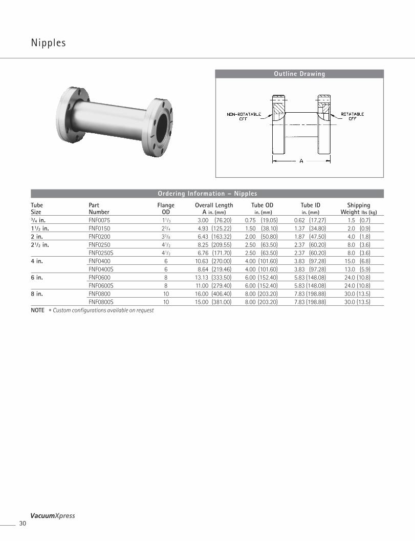
Nipples
30
Tube Part Flange Overall Length Tube OD Tube ID ShippingSize Number OD A in. (mm) in. (mm) in. (mm) Weight lbs (kg)3⁄4 in. FNF0075 11⁄3 3.00 (76.20) 0.75 (19.05) 0.62 (17.27) 1.5 (0.7)11⁄2 in. FNF0150 23⁄4 4.93 (125.22) 1.50 (38.10) 1.37 (34.80) 2.0 (0.9)2 in. FNF0200 33⁄8 6.43 (163.32) 2.00 (50.80) 1.87 (47.50) 4.0 (1.8) 21⁄2 in. FNF0250 41⁄2 8.25 (209.55) 2.50 (63.50) 2.37 (60.20) 8.0 (3.6)
FNF0250S 41⁄2 6.76 (171.70) 2.50 (63.50) 2.37 (60.20) 8.0 (3.6)4 in. FNF0400 6 10.63 (270.00) 4.00 (101.60) 3.83 (97.28) 15.0 (6.8)
FNF0400S 6 8.64 (219.46) 4.00 (101.60) 3.83 (97.28) 13.0 (5.9)6 in. FNF0600 8 13.13 (333.50) 6.00 (152.40) 5.83 (148.08) 24.0 (10.8)
FNF0600S 8 11.00 (279.40) 6.00 (152.40) 5.83 (148.08) 24.0 (10.8)8 in. FNF0800 10 16.00 (406.40) 8.00 (203.20) 7.83 (198.88) 30.0 (13.5)
FNF0800S 10 15.00 (381.00) 8.00 (203.20) 7.83 (198.88) 30.0 (13.5)NOTE • Custom configurations available on request
Ordering Information – Nipples
Outline Drawing
ComponentsConFlat® F i t t ings
Elbows (90°)
31Varian, Inc. Vacuum Technologies
Com
pone
nts
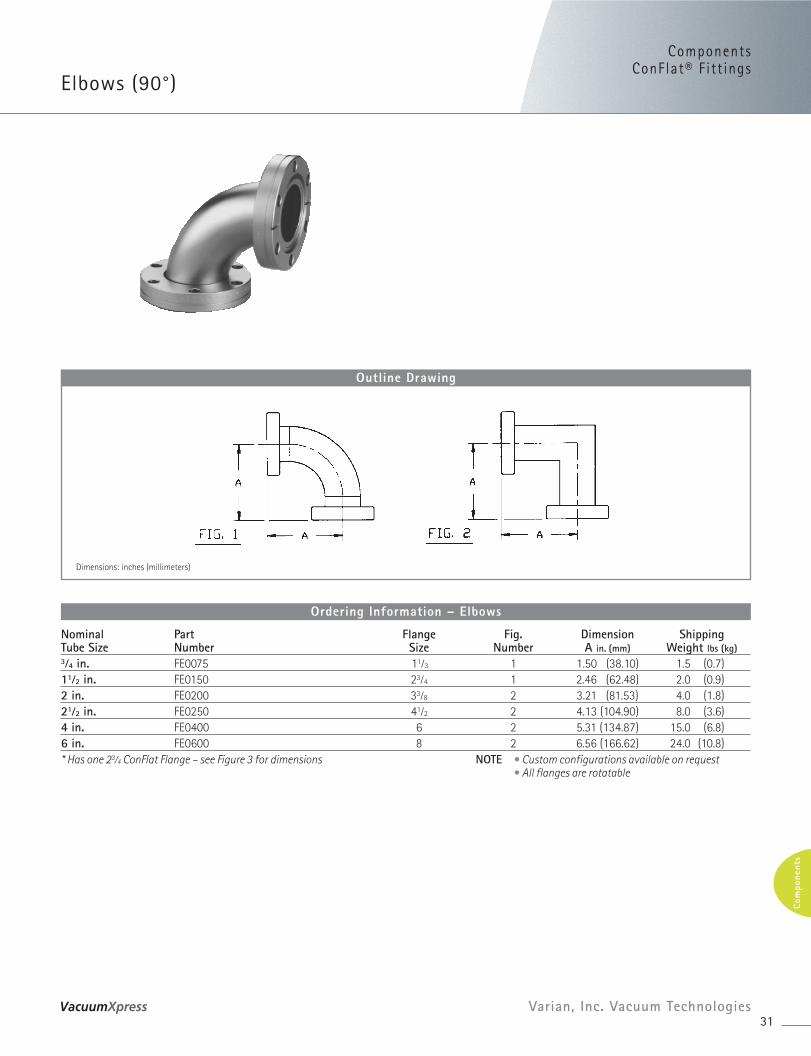
Nominal Part Flange Fig. Dimension ShippingTube Size Number Size Number A in. (mm) Weight lbs (kg)3⁄4 in. FE0075 11⁄3 1 1.50 (38.10) 1.5 (0.7)11⁄2 in. FE0150 23⁄4 1 2.46 (62.48) 2.0 (0.9)2 in. FE0200 33⁄8 2 3.21 (81.53) 4.0 (1.8)21⁄2 in. FE0250 41⁄2 2 4.13 (104.90) 8.0 (3.6)4 in. FE0400 6 2 5.31 (134.87) 15.0 (6.8)6 in. FE0600 8 2 6.56 (166.62) 24.0 (10.8)* Has one 23⁄4 ConFlat Flange – see Figure 3 for dimensions NOTE • Custom configurations available on request
• All flanges are rotatable
Ordering Information – Elbows
Outline Drawing
Dimensions: inches (millimeters)
Crosses (4-Way)
Tees
32
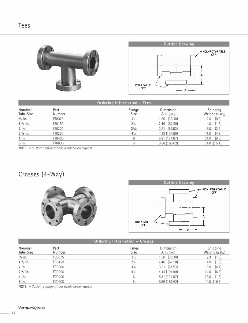
Nominal Part Flange Dimension ShippingTube Size Number Size A in. (mm) Weight lbs (kg)3⁄4 in. FT0075 11⁄3 1.50 (38.10) 2.0 (0.9)11⁄2 in. FT0150 23⁄4 2.46 (62.50) 4.0 (1.8)2 in. FT0200 33⁄8 3.21 (81.53) 8.0 (3.6)21⁄2 in. FT0250 41⁄2 4.13 (104.90) 11.0 (4.9)4 in. FT0400 6 5.31 (134.87) 21.0 (9.5)6 in. FT0600 8 6.56 (166.62) 34.0 (15.4)NOTE • Custom configurations available on request
Ordering Information – Tees
Outline Drawing
Nominal Part Flange Dimension ShippingTube Size Number Size A in. (mm) Weight lbs (kg)3⁄4 in. FC0075 11⁄3 1.50 (38.10) 2.3 (1.0)11⁄2 in. FC0150 23⁄4 2.46 (62.50) 4.0 (1.8)2 in. FC0200 33⁄8 3.21 (81.53) 9.0 (4.1)21⁄2 in. FC0250 41⁄2 4.13 (104.90) 14.0 (6.3)4 in. FC0400 6 5.31 (134.87) 26.0 (11.8)6 in. FC0600 8 6.56 (166.62) 44.0 (19.9)NOTE • Custom configurations available on request
Ordering Information – Crosses
Outline Drawing
ComponentsConFlat® F i t t ings
Flexible Couplings (Non-Braided)
33Varian, Inc. Vacuum Technologies
Com
pone
nts
Outline Drawing
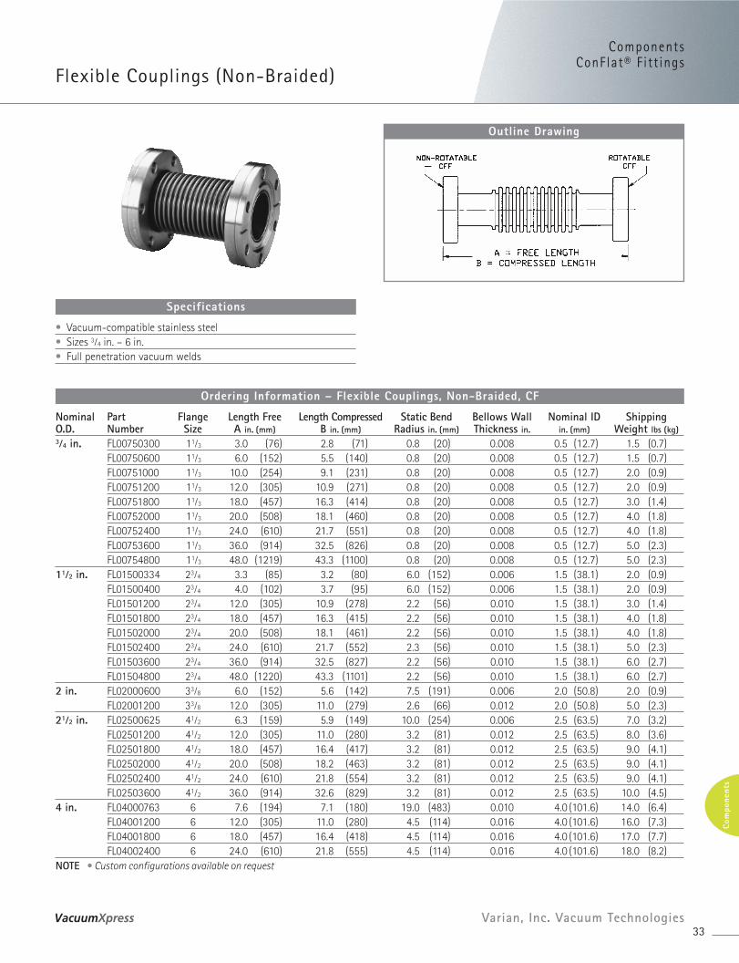
Nominal Part Flange Length Free Length Compressed Static Bend Bellows Wall Nominal ID ShippingO.D. Number Size A in. (mm) B in. (mm) Radius in. (mm) Thickness in. in. (mm) Weight lbs (kg)3⁄4 in. FL00750300 11⁄3 3.0 (76) 2.8 (71) 0.8 (20) 0.008 0.5 (12.7) 1.5 (0.7)
FL00750600 11⁄3 6.0 (152) 5.5 (140) 0.8 (20) 0.008 0.5 (12.7) 1.5 (0.7)FL00751000 11⁄3 10.0 (254) 9.1 (231) 0.8 (20) 0.008 0.5 (12.7) 2.0 (0.9)FL00751200 11⁄3 12.0 (305) 10.9 (271) 0.8 (20) 0.008 0.5 (12.7) 2.0 (0.9)FL00751800 11⁄3 18.0 (457) 16.3 (414) 0.8 (20) 0.008 0.5 (12.7) 3.0 (1.4)FL00752000 11⁄3 20.0 (508) 18.1 (460) 0.8 (20) 0.008 0.5 (12.7) 4.0 (1.8)FL00752400 11⁄3 24.0 (610) 21.7 (551) 0.8 (20) 0.008 0.5 (12.7) 4.0 (1.8)FL00753600 11⁄3 36.0 (914) 32.5 (826) 0.8 (20) 0.008 0.5 (12.7) 5.0 (2.3)FL00754800 11⁄3 48.0 (1219) 43.3 (1100) 0.8 (20) 0.008 0.5 (12.7) 5.0 (2.3)
11⁄2 in. FL01500334 23⁄4 3.3 (85) 3.2 (80) 6.0 (152) 0.006 1.5 (38.1) 2.0 (0.9)FL01500400 23⁄4 4.0 (102) 3.7 (95) 6.0 (152) 0.006 1.5 (38.1) 2.0 (0.9)FL01501200 23⁄4 12.0 (305) 10.9 (278) 2.2 (56) 0.010 1.5 (38.1) 3.0 (1.4)FL01501800 23⁄4 18.0 (457) 16.3 (415) 2.2 (56) 0.010 1.5 (38.1) 4.0 (1.8)FL01502000 23⁄4 20.0 (508) 18.1 (461) 2.2 (56) 0.010 1.5 (38.1) 4.0 (1.8)FL01502400 23⁄4 24.0 (610) 21.7 (552) 2.3 (56) 0.010 1.5 (38.1) 5.0 (2.3)FL01503600 23⁄4 36.0 (914) 32.5 (827) 2.2 (56) 0.010 1.5 (38.1) 6.0 (2.7)FL01504800 23⁄4 48.0 (1220) 43.3 (1101) 2.2 (56) 0.010 1.5 (38.1) 6.0 (2.7)
2 in. FL02000600 33⁄8 6.0 (152) 5.6 (142) 7.5 (191) 0.006 2.0 (50.8) 2.0 (0.9)FL02001200 33⁄8 12.0 (305) 11.0 (279) 2.6 (66) 0.012 2.0 (50.8) 5.0 (2.3)
21⁄2 in. FL02500625 41⁄2 6.3 (159) 5.9 (149) 10.0 (254) 0.006 2.5 (63.5) 7.0 (3.2)FL02501200 41⁄2 12.0 (305) 11.0 (280) 3.2 (81) 0.012 2.5 (63.5) 8.0 (3.6)FL02501800 41⁄2 18.0 (457) 16.4 (417) 3.2 (81) 0.012 2.5 (63.5) 9.0 (4.1)FL02502000 41⁄2 20.0 (508) 18.2 (463) 3.2 (81) 0.012 2.5 (63.5) 9.0 (4.1)FL02502400 41⁄2 24.0 (610) 21.8 (554) 3.2 (81) 0.012 2.5 (63.5) 9.0 (4.1)FL02503600 41⁄2 36.0 (914) 32.6 (829) 3.2 (81) 0.012 2.5 (63.5) 10.0 (4.5)
4 in. FL04000763 6 7.6 (194) 7.1 (180) 19.0 (483) 0.010 4.0 (101.6) 14.0 (6.4)FL04001200 6 12.0 (305) 11.0 (280) 4.5 (114) 0.016 4.0 (101.6) 16.0 (7.3)FL04001800 6 18.0 (457) 16.4 (418) 4.5 (114) 0.016 4.0 (101.6) 17.0 (7.7)FL04002400 6 24.0 (610) 21.8 (555) 4.5 (114) 0.016 4.0 (101.6) 18.0 (8.2)
NOTE • Custom configurations available on request
Ordering Information – Flexible Couplings, Non-Braided, CF
• Vacuum-compatible stainless steel• Sizes 3⁄4 in. – 6 in.• Full penetration vacuum welds
Specifications
Flexible Couplings (Braided)
34
Outline Drawing
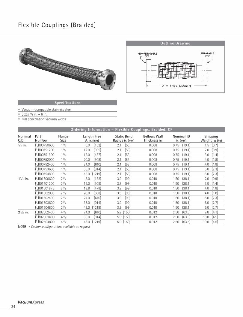
Nominal Part Flange Length Free Static Bend Bellows Wall Nominal ID ShippingO.D. Number Size A in. (mm) Radius in. (mm) Thickness in. in. (mm) Weight lbs (kg)3⁄4 in. FLB00750600 11⁄3 6.0 (152) 2.1 (53) 0.008 0.75 (19.1) 1.5 (0.7)
FLB00751200 11⁄3 12.0 (305) 2.1 (53) 0.008 0.75 (19.1) 2.0 (0.9)FLB00751800 11⁄3 18.0 (457) 2.1 (53) 0.008 0.75 (19.1) 3.0 (1.4)FLB00752000 11⁄3 20.0 (508) 2.1 (53) 0.008 0.75 (19.1) 4.0 (1.8)FLB00752400 11⁄3 24.0 (610) 2.1 (53) 0.008 0.75 (19.1) 4.0 (1.8)FLB00753600 11⁄3 36.0 (914) 2.1 (53) 0.008 0.75 (19.1) 5.0 (2.3)FLB00754800 11⁄3 48.0 (1219) 2.1 (53) 0.008 0.75 (19.1) 5.0 (2.3)
11⁄2 in. FLB01500600 23⁄4 6.0 (152) 3.9 (99) 0.010 1.50 (38.1) 2.0 (0.9)FLB01501200 23⁄4 12.0 (305) 3.9 (99) 0.010 1.50 (38.1) 3.0 (1.4)FLB01501875 23⁄4 18.8 (478) 3.9 (99) 0.010 1.50 (38.1) 4.0 (1.8)FLB01502000 23⁄4 20.0 (508) 3.9 (99) 0.010 1.50 (38.1) 4.0 (1.8)FLB01502400 23⁄4 24.0 (610) 3.9 (99) 0.010 1.50 (38.1) 5.0 (2.3)FLB01503600 23⁄4 36.0 (914) 3.9 (99) 0.010 1.50 (38.1) 6.0 (2.7)FLB01504800 23⁄4 48.0 (1219) 3.9 (99) 0.010 1.50 (38.1) 6.0 (2.7)
21⁄2 in. FLB02502400 41⁄2 24.0 (610) 5.9 (150) 0.012 2.50 (63.5) 9.0 (4.1)FLB02503600 41⁄2 36.0 (914) 5.9 (150) 0.012 2.50 (63.5) 10.0 (4.5)FLB02504800 41⁄2 48.0 (1219) 5.9 (150) 0.012 2.50 (63.5) 10.0 (4.5)
NOTE • Custom configurations available on request
Ordering Information – Flexible Couplings, Braided, CF
• Vacuum-compatible stainless steel• Sizes 3⁄4 in. – 6 in.• Full penetration vacuum welds
Specifications
ComponentsComponentsConFlat® F i t t ings
CFF to KF Adapters
35Varian, Inc. Vacuum Technologies
Com
pone
nts
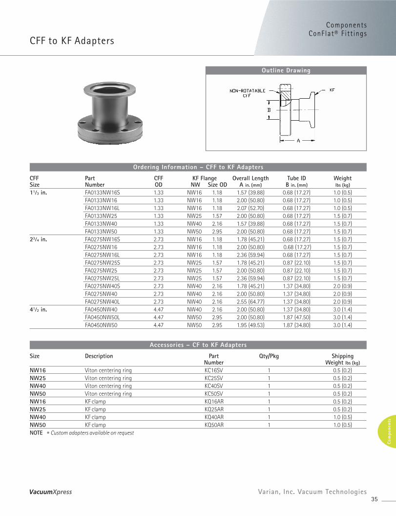
Outline Drawing
CFF Part CFF KF Flange Overall Length Tube ID WeightSize Number OD NW Size OD A in. (mm) B in. (mm) lbs (kg)
11⁄3 in. FA0133NW16S 1.33 NW16 1.18 1.57 (39.88) 0.68 (17.27) 1.0 (0.5)FA0133NW16 1.33 NW16 1.18 2.00 (50.80) 0.68 (17.27) 1.0 (0.5)FA0133NW16L 1.33 NW16 1.18 2.07 (52.70) 0.68 (17.27) 1.0 (0.5)FA0133NW25 1.33 NW25 1.57 2.00 (50.80) 0.68 (17.27) 1.5 (0.7)FA0133NW40 1.33 NW40 2.16 1.57 (39.88) 0.68 (17.27) 1.5 (0.7)FA0133NW50 1.33 NW50 2.95 2.00 (50.80) 0.68 (17.27) 1.5 (0.7)
23⁄4 in. FA0275NW16S 2.73 NW16 1.18 1.78 (45.21) 0.68 (17.27) 1.5 (0.7)FA0275NW16 2.73 NW16 1.18 2.00 (50.80) 0.68 (17.27) 1.5 (0.7)FA0275NW16L 2.73 NW16 1.18 2.36 (59.94) 0.68 (17.27) 1.5 (0.7)FA0275NW25S 2.73 NW25 1.57 1.78 (45.21) 0.87 (22.10) 1.5 (0.7)FA0275NW25 2.73 NW25 1.57 2.00 (50.80) 0.87 (22.10) 1.5 (0.7)FA0275NW25L 2.73 NW25 1.57 2.36 (59.94) 0.87 (22.10) 1.5 (0.7)FA0275NW40S 2.73 NW40 2.16 1.78 (45.21) 1.37 (34.80) 2.0 (0.9)FA0275NW40 2.73 NW40 2.16 2.00 (50.80) 1.37 (34.80) 2.0 (0.9)FA0275NW40L 2.73 NW40 2.16 2.55 (64.77) 1.37 (34.80) 2.0 (0.9)
41⁄2 in. FA0450NW40 4.47 NW40 2.16 2.00 (50.80) 1.37 (34.80) 3.0 (1.4)FA0450NW50L 4.47 NW50 2.95 2.00 (50.80) 1.87 (47.50) 3.0 (1.4)FA0450NW50 4.47 NW50 2.95 1.95 (49.53) 1.87 (34.80) 3.0 (1.4)
Ordering Information – CFF to KF Adapters
Size Description Part Qty/Pkg ShippingNumber Weight lbs (kg)
NW16 Viton centering ring KC16SV 1 0.5 (0.2)NW25 Viton centering ring KC25SV 1 0.5 (0.2)NW40 Viton centering ring KC40SV 1 0.5 (0.2)NW50 Viton centering ring KC50SV 1 0.5 (0.2)NW16 KF clamp KQ16AR 1 0.5 (0.2)NW25 KF clamp KQ25AR 1 0.5 (0.2)NW40 KF clamp KQ40AR 1 1.0 (0.5)NW50 KF clamp KQ50AR 1 1.0 (0.5)NOTE • Custom adapters available on request
Accessories – CF to KF Adapters
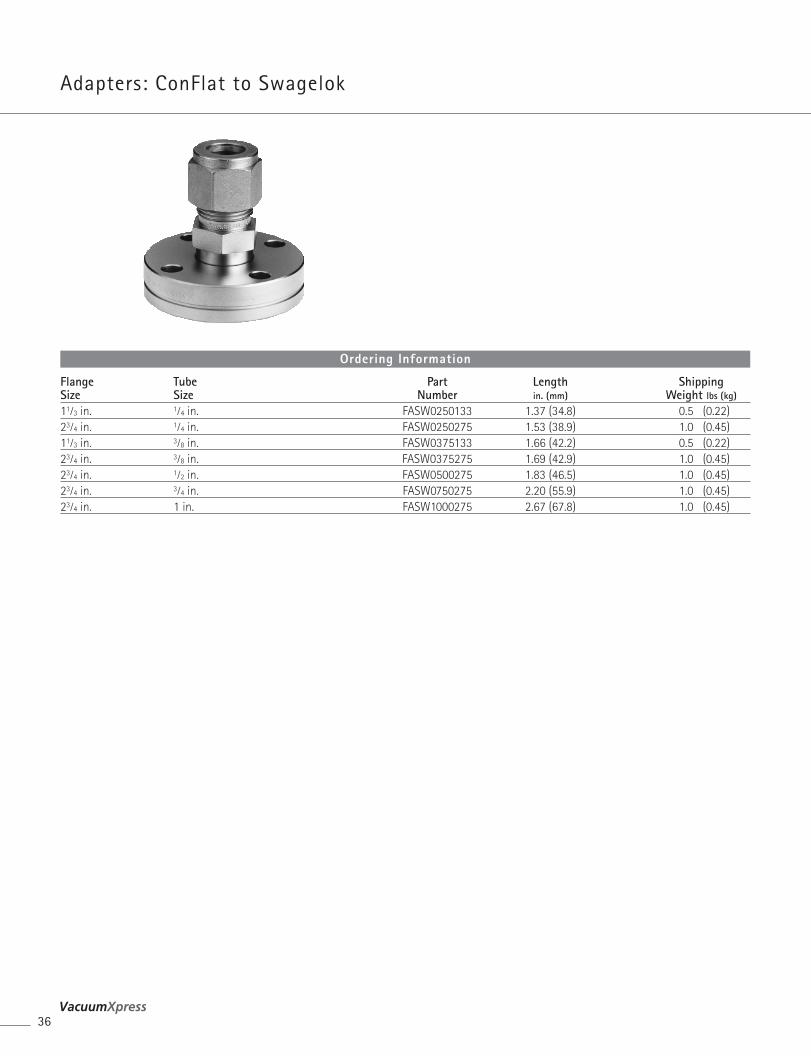
Flange Tube Part Length ShippingSize Size Number in. (mm) Weight lbs (kg)
11⁄3 in. 1⁄4 in. FASW0250133 1.37 (34.8) 0.5 (0.22)23⁄4 in. 1⁄4 in. FASW0250275 1.53 (38.9) 1.0 (0.45)11⁄3 in. 3⁄8 in. FASW0375133 1.66 (42.2) 0.5 (0.22)23⁄4 in. 3⁄8 in. FASW0375275 1.69 (42.9) 1.0 (0.45)23⁄4 in. 1⁄2 in. FASW0500275 1.83 (46.5) 1.0 (0.45)23⁄4 in. 3⁄4 in. FASW0750275 2.20 (55.9) 1.0 (0.45)23⁄4 in. 1 in. FASW1000275 2.67 (67.8) 1.0 (0.45)
Ordering Information
Adapters: ConFlat to Swagelok
36
Components
37
ComponentsConFlat® F i t t ings
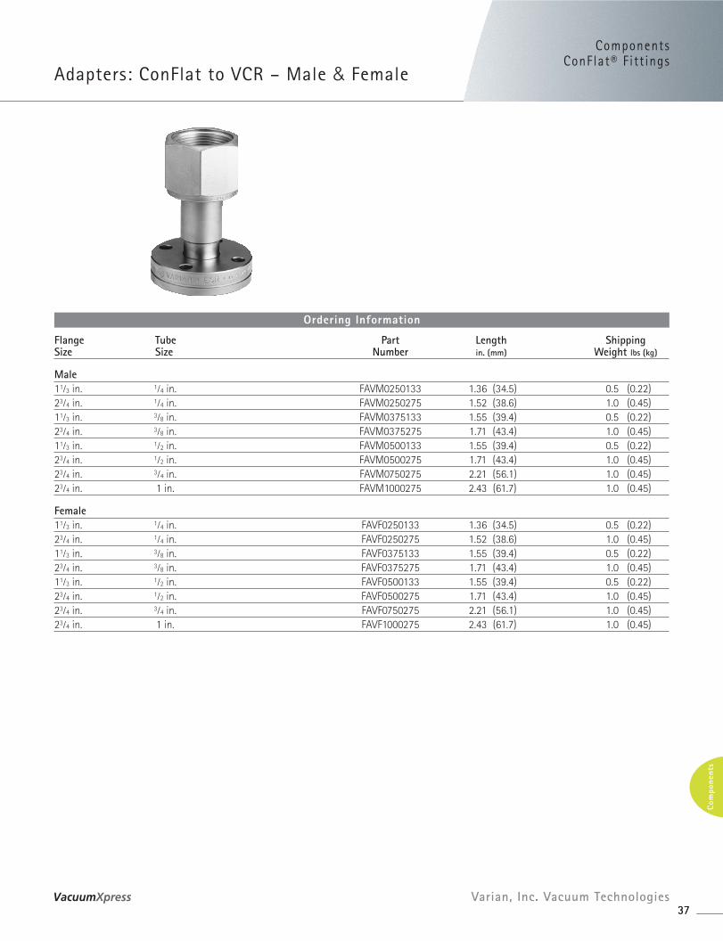
Adapters: ConFlat to VCR – Male & Female
37Varian, Inc. Vacuum Technologies
Com
pone
nts
Flange Tube Part Length ShippingSize Size Number in. (mm) Weight lbs (kg)
Male11⁄3 in. 1⁄4 in. FAVM0250133 1.36 (34.5) 0.5 (0.22)23⁄4 in. 1⁄4 in. FAVM0250275 1.52 (38.6) 1.0 (0.45)11⁄3 in. 3⁄8 in. FAVM0375133 1.55 (39.4) 0.5 (0.22)23⁄4 in. 3⁄8 in. FAVM0375275 1.71 (43.4) 1.0 (0.45)11⁄3 in. 1⁄2 in. FAVM0500133 1.55 (39.4) 0.5 (0.22)23⁄4 in. 1⁄2 in. FAVM0500275 1.71 (43.4) 1.0 (0.45)23⁄4 in. 3⁄4 in. FAVM0750275 2.21 (56.1) 1.0 (0.45)23⁄4 in. 1 in. FAVM1000275 2.43 (61.7) 1.0 (0.45)
Female11⁄3 in. 1⁄4 in. FAVF0250133 1.36 (34.5) 0.5 (0.22)23⁄4 in. 1⁄4 in. FAVF0250275 1.52 (38.6) 1.0 (0.45)11⁄3 in. 3⁄8 in. FAVF0375133 1.55 (39.4) 0.5 (0.22)23⁄4 in. 3⁄8 in. FAVF0375275 1.71 (43.4) 1.0 (0.45)11⁄3 in. 1⁄2 in. FAVF0500133 1.55 (39.4) 0.5 (0.22)23⁄4 in. 1⁄2 in. FAVF0500275 1.71 (43.4) 1.0 (0.45)23⁄4 in. 3⁄4 in. FAVF0750275 2.21 (56.1) 1.0 (0.45)23⁄4 in. 1 in. FAVF1000275 2.43 (61.7) 1.0 (0.45)
Ordering Information
Outline Drawing
Dimensions: inches (millimeters)
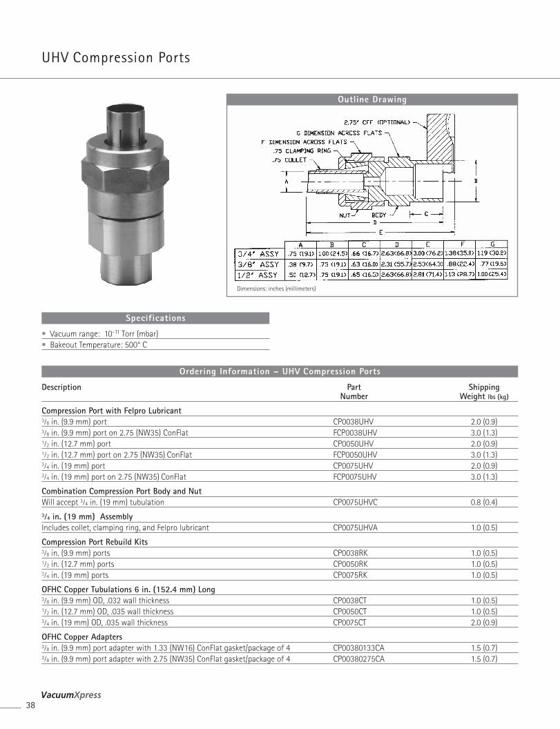
Description Part ShippingNumber Weight lbs (kg)
Compression Port with Felpro Lubricant3⁄8 in. (9.9 mm) port CP0038UHV 2.0 (0.9)3⁄8 in. (9.9 mm) port on 2.75 (NW35) ConFlat FCP0038UHV 3.0 (1.3)1⁄2 in. (12.7 mm) port CP0050UHV 2.0 (0.9)1⁄2 in. (12.7 mm) port on 2.75 (NW35) ConFlat FCP0050UHV 3.0 (1.3)3⁄4 in. (19 mm) port CP0075UHV 2.0 (0.9)3⁄4 in. (19 mm) port on 2.75 (NW35) ConFlat FCP0075UHV 3.0 (1.3)
Combination Compression Port Body and NutWill accept 3⁄4 in. (19 mm) tubulation CP0075UHVC 0.8 (0.4)3⁄4 in. (19 mm) Assembly Includes collet, clamping ring, and Felpro lubricant CP0075UHVA 1.0 (0.5)
Compression Port Rebuild Kits3⁄8 in. (9.9 mm) ports CP0038RK 1.0 (0.5)1⁄2 in. (12.7 mm) ports CP0050RK 1.0 (0.5)3⁄4 in. (19 mm) ports CP0075RK 1.0 (0.5)
OFHC Copper Tubulations 6 in. (152.4 mm) Long3⁄8 in. (9.9 mm) OD, .032 wall thickness CP0038CT 1.0 (0.5)1⁄2 in. (12.7 mm) OD, .035 wall thickness CP0050CT 1.0 (0.5)3⁄4 in. (19 mm) OD, .035 wall thickness CP0075CT 2.0 (0.9)
OFHC Copper Adapters3⁄8 in. (9.9 mm) port adapter with 1.33 (NW16) ConFlat gasket/package of 4 CP00380133CA 1.5 (0.7)3⁄8 in. (9.9 mm) port adapter with 2.75 (NW35) ConFlat gasket/package of 4 CP00380275CA 1.5 (0.7)
Ordering Information – UHV Compression Ports
• Vacuum range: 10-11 Torr (mbar)• Bakeout Temperature: 500° C
Specifications
UHV Compression Ports
38
ComponentsComponentsConFlat® F i t t ings
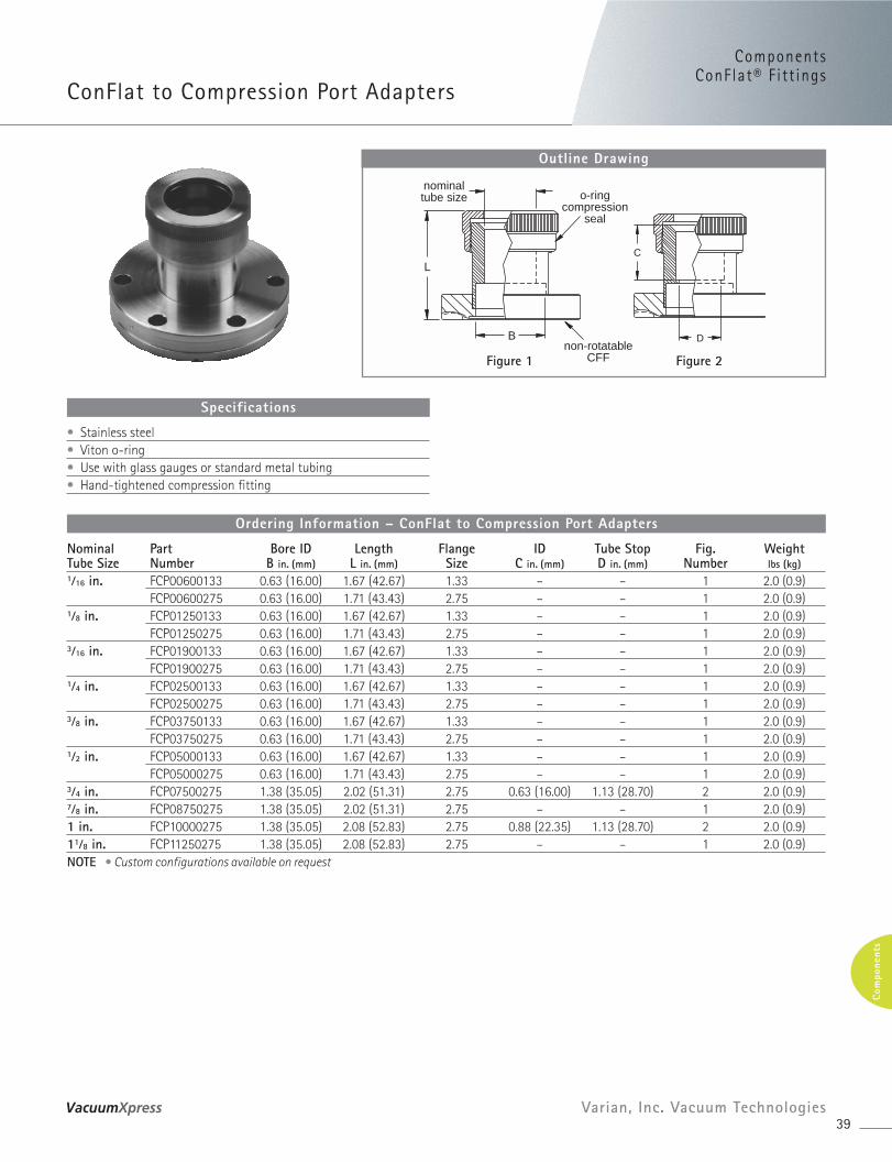
ConFlat to Compression Port Adapters
39Varian, Inc. Vacuum Technologies
Com
pone
nts
nominaltube size o-ring
compressionseal
non-rotatableCFF
L
B
C
D
Outline Drawing
Figure 1 Figure 2
Nominal Part Bore ID Length Flange ID Tube Stop Fig. WeightTube Size Number B in. (mm) L in. (mm) Size C in. (mm) D in. (mm) Number lbs (kg)1⁄16 in. FCP00600133 0.63 (16.00) 1.67 (42.67) 1.33 – – 1 2.0 (0.9)
FCP00600275 0.63 (16.00) 1.71 (43.43) 2.75 – – 1 2.0 (0.9)1⁄8 in. FCP01250133 0.63 (16.00) 1.67 (42.67) 1.33 – – 1 2.0 (0.9)
FCP01250275 0.63 (16.00) 1.71 (43.43) 2.75 – – 1 2.0 (0.9)3⁄16 in. FCP01900133 0.63 (16.00) 1.67 (42.67) 1.33 – – 1 2.0 (0.9)
FCP01900275 0.63 (16.00) 1.71 (43.43) 2.75 – – 1 2.0 (0.9)1⁄4 in. FCP02500133 0.63 (16.00) 1.67 (42.67) 1.33 – – 1 2.0 (0.9)
FCP02500275 0.63 (16.00) 1.71 (43.43) 2.75 – – 1 2.0 (0.9)3⁄8 in. FCP03750133 0.63 (16.00) 1.67 (42.67) 1.33 – – 1 2.0 (0.9)
FCP03750275 0.63 (16.00) 1.71 (43.43) 2.75 – – 1 2.0 (0.9)1⁄2 in. FCP05000133 0.63 (16.00) 1.67 (42.67) 1.33 – – 1 2.0 (0.9)
FCP05000275 0.63 (16.00) 1.71 (43.43) 2.75 – – 1 2.0 (0.9)3⁄4 in. FCP07500275 1.38 (35.05) 2.02 (51.31) 2.75 0.63 (16.00) 1.13 (28.70) 2 2.0 (0.9)7⁄8 in. FCP08750275 1.38 (35.05) 2.02 (51.31) 2.75 – – 1 2.0 (0.9)1 in. FCP10000275 1.38 (35.05) 2.08 (52.83) 2.75 0.88 (22.35) 1.13 (28.70) 2 2.0 (0.9)11⁄8 in. FCP11250275 1.38 (35.05) 2.08 (52.83) 2.75 – – 1 2.0 (0.9)NOTE • Custom configurations available on request
Ordering Information – ConFlat to Compression Port Adapters
• Stainless steel• Viton o-ring• Use with glass gauges or standard metal tubing• Hand-tightened compression fitting
Specifications
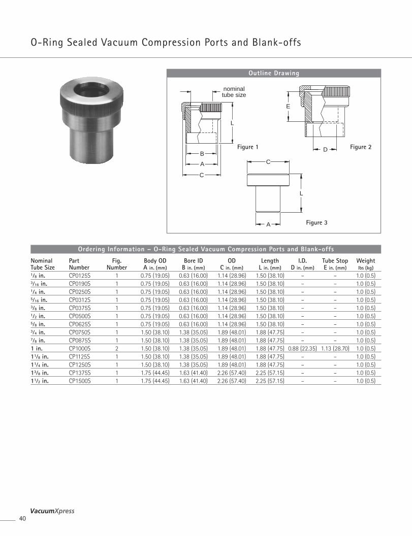
O-Ring Sealed Vacuum Compression Ports and Blank-offs
40
Nominal Part Fig. Body OD Bore ID OD Length I.D. Tube Stop WeightTube Size Number Number A in. (mm) B in. (mm) C in. (mm) L in. (mm) D in. (mm) E in. (mm) lbs (kg)1⁄8 in. CP0125S 1 0.75 (19.05) 0.63 (16.00) 1.14 (28.96) 1.50 (38.10) – – 1.0 (0.5)3⁄16 in. CP0190S 1 0.75 (19.05) 0.63 (16.00) 1.14 (28.96) 1.50 (38.10) – – 1.0 (0.5)1⁄4 in. CP0250S 1 0.75 (19.05) 0.63 (16.00) 1.14 (28.96) 1.50 (38.10) – – 1.0 (0.5)5⁄16 in. CP0312S 1 0.75 (19.05) 0.63 (16.00) 1.14 (28.96) 1.50 (38.10) – – 1.0 (0.5)3⁄8 in. CP0375S 1 0.75 (19.05) 0.63 (16.00) 1.14 (28.96) 1.50 (38.10) – – 1.0 (0.5)1⁄2 in. CP0500S 1 0.75 (19.05) 0.63 (16.00) 1.14 (28.96) 1.50 (38.10) – – 1.0 (0.5)5⁄8 in. CP0625S 1 0.75 (19.05) 0.63 (16.00) 1.14 (28.96) 1.50 (38.10) – – 1.0 (0.5)3⁄4 in. CP0750S 1 1.50 (38.10) 1.38 (35.05) 1.89 (48.01) 1.88 (47.75) – – 1.0 (0.5)7⁄8 in. CP0875S 1 1.50 (38.10) 1.38 (35.05) 1.89 (48.01) 1.88 (47.75) – – 1.0 (0.5)1 in. CP1000S 2 1.50 (38.10) 1.38 (35.05) 1.89 (48.01) 1.88 (47.75) 0.88 (22.35) 1.13 (28.70) 1.0 (0.5)11⁄8 in. CP1125S 1 1.50 (38.10) 1.38 (35.05) 1.89 (48.01) 1.88 (47.75) – – 1.0 (0.5)11⁄4 in. CP1250S 1 1.50 (38.10) 1.38 (35.05) 1.89 (48.01) 1.88 (47.75) – – 1.0 (0.5)13⁄8 in. CP1375S 1 1.75 (44.45) 1.63 (41.40) 2.26 (57.40) 2.25 (57.15) – – 1.0 (0.5)11⁄2 in. CP1500S 1 1.75 (44.45) 1.63 (41.40) 2.26 (57.40) 2.25 (57.15) – – 1.0 (0.5)
Ordering Information – O-Ring Sealed Vacuum Compression Ports and Blank-offs
nominaltube size
B
C
A
L
C
L
A
D
E
Outline Drawing
Figure 2Figure 1
Figure 3
Components
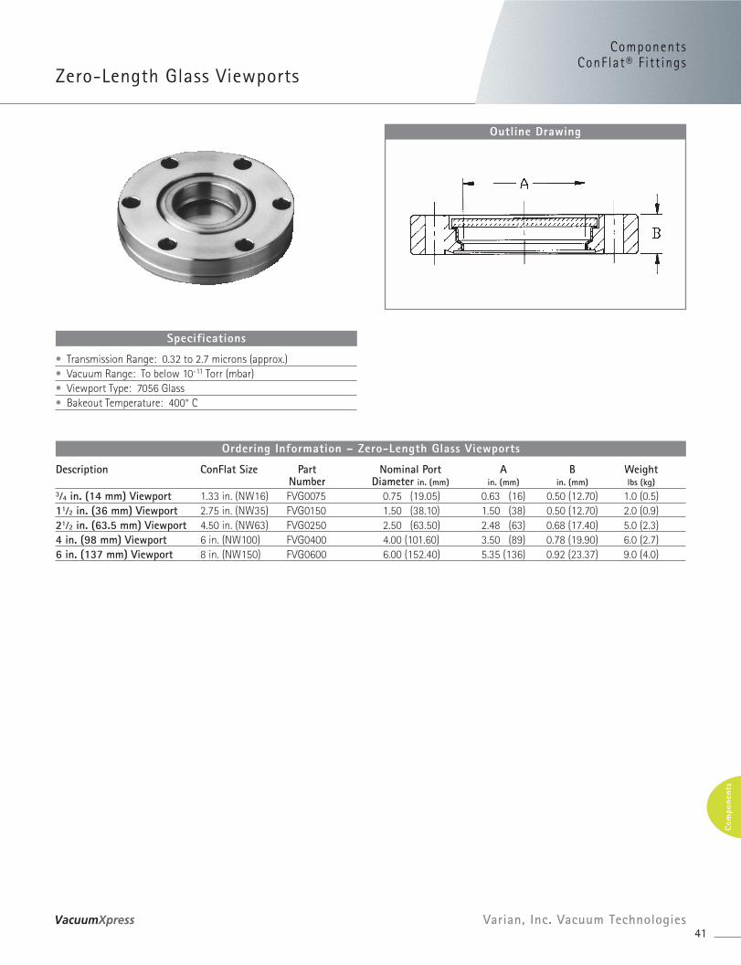
Zero-Length Glass Viewports
ComponentsConFlat® F i t t ings
41Varian, Inc. Vacuum Technologies
Com
pone
nts
Description ConFlat Size Part Nominal Port A B WeightNumber Diameter in. (mm) in. (mm) in. (mm) lbs (kg)
3⁄4 in. (14 mm) Viewport 1.33 in. (NW16) FVG0075 0.75 (19.05) 0.63 (16) 0.50 (12.70) 1.0 (0.5)11⁄2 in. (36 mm) Viewport 2.75 in. (NW35) FVG0150 1.50 (38.10) 1.50 (38) 0.50 (12.70) 2.0 (0.9)21⁄2 in. (63.5 mm) Viewport 4.50 in. (NW63) FVG0250 2.50 (63.50) 2.48 (63) 0.68 (17.40) 5.0 (2.3)4 in. (98 mm) Viewport 6 in. (NW100) FVG0400 4.00 (101.60) 3.50 (89) 0.78 (19.90) 6.0 (2.7)6 in. (137 mm) Viewport 8 in. (NW150) FVG0600 6.00 (152.40) 5.35 (136) 0.92 (23.37) 9.0 (4.0)
Ordering Information – Zero-Length Glass Viewports
Outline Drawing
• Transmission Range: 0.32 to 2.7 microns (approx.)• Vacuum Range: To below 10-11 Torr (mbar)• Viewport Type: 7056 Glass• Bakeout Temperature: 400° C
Specifications
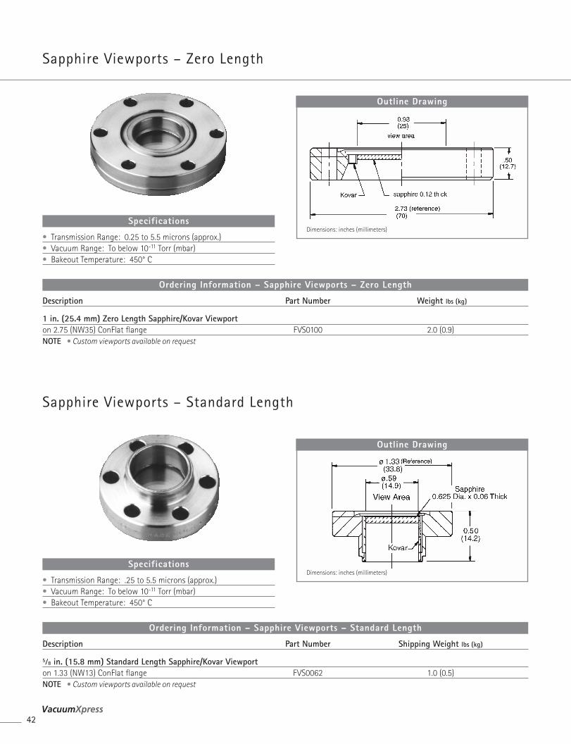
Sapphire Viewports – Standard Length
Description Part Number Shipping Weight lbs (kg)
5⁄8 in. (15.8 mm) Standard Length Sapphire/Kovar Viewporton 1.33 (NW13) ConFlat flange FVS0062 1.0 (0.5)NOTE • Custom viewports available on request
Ordering Information – Sapphire Viewports – Standard Length
Outline Drawing
Dimensions: inches (millimeters)• Transmission Range: .25 to 5.5 microns (approx.)• Vacuum Range: To below 10-11 Torr (mbar)• Bakeout Temperature: 450° C
Specifications
Sapphire Viewports – Zero Length
42
Description Part Number Weight lbs (kg)
1 in. (25.4 mm) Zero Length Sapphire/Kovar Viewporton 2.75 (NW35) ConFlat flange FVS0100 2.0 (0.9)NOTE • Custom viewports available on request
Ordering Information – Sapphire Viewports – Zero Length
Outline Drawing
Dimensions: inches (millimeters)• Transmission Range: 0.25 to 5.5 microns (approx.)• Vacuum Range: To below 10-11 Torr (mbar)• Bakeout Temperature: 450° C
Specifications
ComponentsComponentsConFlat® F i t t ings
43Varian, Inc. Vacuum Technologies
Com
pone
nts
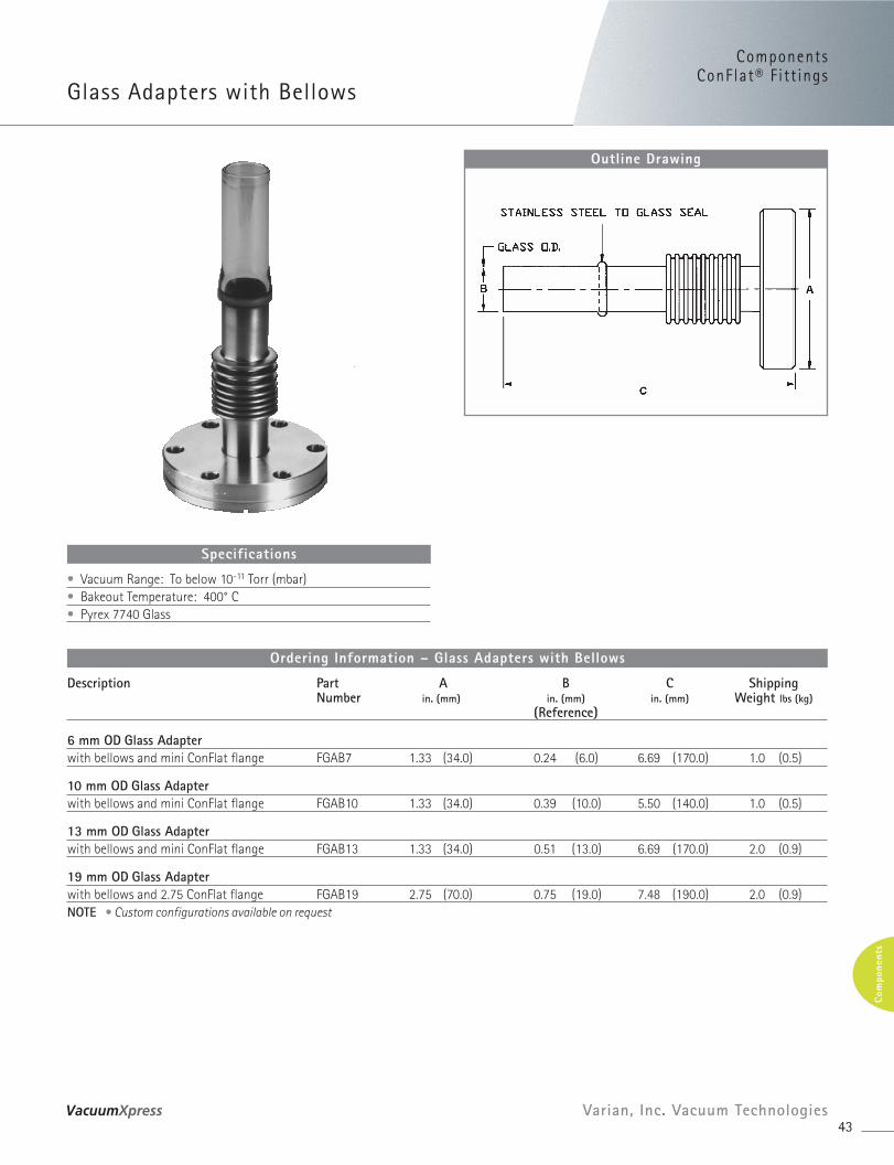
Glass Adapters with Bellows
Description Part A B C ShippingNumber in. (mm) in. (mm) in. (mm) Weight lbs (kg)
(Reference)
6 mm OD Glass Adapterwith bellows and mini ConFlat flange FGAB7 1.33 (34.0) 0.24 (6.0) 6.69 (170.0) 1.0 (0.5)
10 mm OD Glass Adapterwith bellows and mini ConFlat flange FGAB10 1.33 (34.0) 0.39 (10.0) 5.50 (140.0) 1.0 (0.5)
13 mm OD Glass Adapterwith bellows and mini ConFlat flange FGAB13 1.33 (34.0) 0.51 (13.0) 6.69 (170.0) 2.0 (0.9)
19 mm OD Glass Adapterwith bellows and 2.75 ConFlat flange FGAB19 2.75 (70.0) 0.75 (19.0) 7.48 (190.0) 2.0 (0.9)NOTE • Custom configurations available on request
Ordering Information – Glass Adapters with Bellows
Outline Drawing
• Vacuum Range: To below 10-11 Torr (mbar)• Bakeout Temperature: 400° C• Pyrex 7740 Glass
Specifications
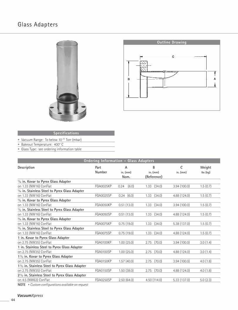
Glass Adapters
Description Part A B C WeightNumber in. (mm) in. (mm) in. (mm) lbs (kg)
Nom. (Reference)1⁄4 in. Kovar to Pyrex Glass Adapteron 1.33 (NW16) ConFlat FGA0025KP 0.24 (6.0) 1.33 (34.0) 3.94 (100.0) 1.5 (0.7)1⁄4 in. Stainless Steel to Pyrex Glass Adapteron 1.33 (NW16) ConFlat FGA0025SP 0.24 (6.0) 1.33 (34.0) 4.88 (124.0) 1.5 (0.7)1⁄2 in. Kovar to Pyrex Glass Adapteron 1.33 (NW16) ConFlat FGA0050KP 0.51 (13.0) 1.33 (34.0) 3.94 (100.0) 1.5 (0.7)1⁄2 in. Stainless Steel to Pyrex Glass Adapteron 1.33 (NW16) ConFlat FGA0050SP 0.51 (13.0) 1.33 (34.0) 4.88 (124.0) 1.5 (0.7)3⁄4 in. Kovar to Pyrex Glass Adapteron 1.33 (NW16) ConFlat FGA0075KP 0.75 (19.0) 1.33 (34.0) 5.38 (137.0) 1.5 (0.7)3⁄4 in. Stainless Steel to Pyrex Glass Adapteron 1.33 (NW16) ConFlat FGA0075SP 0.75 (19.0) 1.33 (34.0) 4.88 (124.0) 1.5 (0.7)1 in. Kovar to Pyrex Glass Adapteron 2.75 (NW35) ConFlat FGA0100KP 1.00 (25.0) 2.75 (70.0) 3.94 (100.0) 3.0 (1.4)1 in. Stainless Steel to Pyrex Glass Adapteron 2.75 (NW35) ConFlat FGA0100SP 1.00 (25.0) 2.75 (70.0) 4.88 (124.0) 3.0 (1.4)11⁄2 in. Kovar to Pyrex Glass Adapteron 2.75 (NW35) ConFlat FGA0150KP 1.57 (40.0) 2.75 (70.0) 3.94 (100.0) 4.0 (1.8)11⁄2 in. Stainless Steel to Pyrex Glass Adapteron 2.75 (NW35) ConFlat FGA0150SP 1.50 (38.0) 2.75 (70.0) 4.88 (124.0) 4.0 (1.8)21⁄2 in. Stainless Steel to Pyrex Glass Adapteron 4.5 (NW63) ConFlat FGA0250SP 2.50 (64.0) 4.50 (114.0) 5.33 (137.0) 5.0 (2.3)NOTE • Custom configurations available on request
Ordering Information – Glass Adapters
Outline Drawing
• Vacuum Range: To below 10-11 Torr (mbar)• Bakeout Temperature: 400° C• Glass Type: see ordering information table
Specifications
44

ComponentsComponentsConFlat® F i t t ings
45Varian, Inc. Vacuum Technologies
Com
pone
nts
UHV Wire-Sealed Flange – Wheeler
Outline Drawing
Dimensions: inches (millimeters)
• Vacuum Range: To below 10-11 Torr (mbar)• –169° C to + 450° C
Specifications
Part Gasket Gasket Qty/Pkg ShippingNumber ID Thickness (in.) Weight lbs (kg)
Copper GasketsWG1200 13.74 (349.0) 0.091 3 2.0 (.9)WG1400 15.74 (399.8) 0.091 3 2.0 (.9)WG1800 19.74 (501.4) 0.091 3 3.0 (1.3)
Clamp AssemblyWCSI 1 .5 (.2)
Accessories – UHV Wire-Sealed Flange
46
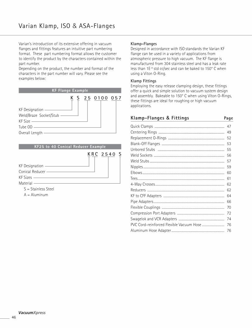
Varian Klamp, ISO & ASA-Flanges
Klamp-FlangesDesigned in accordance with ISO standards the Varian KFflange can be used in a variety of applications fromatmospheric pressure to high vacuum. The KF flange ismanufactured from 304 stainless steel and has a leak rateless than 1E-9 std cc/sec and can be baked to 150° C whenusing a Viton O-Ring.
Klamp FittingsEmploying the easy release clamping design, these fittingsoffer a quick and simple solution to vacuum system designand assembly. Bakeable to 150° C when using Viton O-Rings,these fittings are ideal for roughing or high vacuumapplications.
Klamp-Flanges & Fittings Page
Quick Clamps ....................................................................................... 47Centering Rings .................................................................................. 49Replacement O-Rings ...................................................................... 52Blank-Off Flanges .............................................................................. 53Unbored Stubs ................................................................................... 55Weld Sockets ........................................................................................ 56Weld Stubs ............................................................................................. 57Nipples ..................................................................................................... 59Elbows ...................................................................................................... 60Tees............................................................................................................ 614-Way Crosses ...................................................................................... 62Reducers ................................................................................................ 62KF to CFF Adapters ............................................................................ 64Pipe Adapters ........................................................................................ 66Flexible Couplings .............................................................................. 70Compression Port Adapters ........................................................... 72Swagelok and VCR Adapters ......................................................... 74PVC Cord-reinforced Flexible Vacuum Hose ............................ 76Aluminum Hose Adapter .................................................................. 76
KF Flange Example
K S 2 5 0 1 0 0 0 5 7
KF DesignationWeld/Braze Socket/StubKF SizeTube ODOverall Length
Varian’s introduction of its extensive offering in vacuumflanges and fittings features an intuitive part numberingformat. These part numbering format allows the customerto identify the product by the characters contained within thepart number.Depending on the product, the number and format of thecharacters in the part number will vary. Please see theexamples below:
KF25 to 40 Conical Reducer Example
K R C 2 5 4 0 S
KF DesignationConical ReducerKF SizesMaterial
S = Stainless SteelA = Aluminum
Com
pone
nts
ComponentsKlamp F langes & Fitt ings
47Varian, Inc. Vacuum Technologies
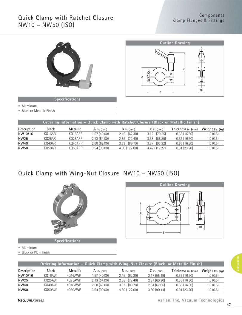
Quick Clamp with Ratchet ClosureNW10 – NW50 (ISO)
Description Black Metallic A in. (mm) B in. (mm) C in. (mm) Thickness in. (mm) Weight lbs. (kg)
NW10/16 KQ16AR KQ16ARP 1.57 (40.00) 2.45 (62,30) 3.12 (79.25) 0.65 (16.50) 1.0 (0.5)NW25 KQ25AR KQ25ARP 2.13 (54.00) 2.85 (72.40) 3.38 (85.85) 0.65 (16.50) 1.0 (0.5)NW40 KQ40AR KQ40ARP 2.68 (68.00) 3.53 (89.70) 3.67 (93.22) 0.65 (16.50) 1.0 (0.5)NW50 KQ50AR KQ50ARP 3.54 (90.00) 4.80 (122.00) 4.42 (112.27) 0.91 (23.20) 1.0 (0.5)
Ordering Information – Quick Clamp with Ratchet Closure (Black or Metallic Finish)
Outline Drawing
• Aluminum• Black or Metallic Finish
Specifications
Quick Clamp with Wing-Nut Closure NW10 – NW50 (ISO)
Description Black Metallic A in. (mm) B in. (mm) C in. (mm) Thickness in. (mm) Weight lbs. (kg)
NW10/16 KQ16AW KQ16AWP 1.57 (40.00) 2.45 (62.30) 2.17 (55.19) 0.65 (16.50) 1.0 (0.5)NW25 KQ25AW KQ25AWP 2.13 (54.00) 2.85 (72.40) 2.37 (60.20) 0.65 (16.50) 1.0 (0.5)NW40 KQ40AW KQ40AWP 2.68 (68.00) 3.53 (89.70) 2.64 (67.06) 0.65 (16.50) 1.0 (0.5)NW50 KQ50AW KQ50AWP 3.54 (90.00) 4.80 (122.00) 3.60 (90.44) 0.91 (23.20) 1.0 (0.5)
Ordering Information – Quick Clamp with Wing-Nut Closure (Black or Metallic Finish)
Outline Drawing
• Aluminum• Black or Plain finish
Specifications
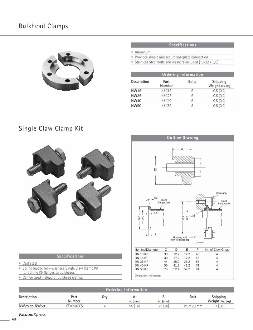
Bulkhead Clamps
48
Description Part Qty A B Bolt ShippingNumber in. (mm) in. (mm) Weight lbs. (kg)
NW25 to NW50 KF1050CCS 4 .55 (14) .79 (20) M6 x 20 mm .11 (.05)
Ordering Information
• Cast steel• Spring loaded lock-washers, Single Claw Clamp Kit
for bolting KF flanges to bulkheads• Can be used instead of bulkhead clamps
Specifications
Single Claw Clamp KitOutline Drawing
NominalDiameter C D E F Nr. of Claw Grips
DN 10 KF 30 12.2 12.2 45 4DN 16 KF 30 17.2 17.2 45 4DN 25 KF 44 26.2 26.2 55 4DN 40 KF 55 41.2 41.2 71 4DN 50 KF 75 52.4 52.2 91 4
Dimensions: millimeters
Description Part Bolts ShippingNumber Weight lbs. (kg)
NW16 KBC16 6 0.5 (0.2)NW25 KBC25 6 0.5 (0.2)NW40 KBC40 6 0.5 (0.2)NW50 KBC50 8 0.5 (0.2)
Ordering Information
• Aluminum• Provides simple and secure baseplate connection• Stainless Steel bolts and washers included (10-32 x 5/8)
Specifications
ComponentsKlamp F langes & Fitt ings
49Varian, Inc. Vacuum Technologies
Com
pone
nts
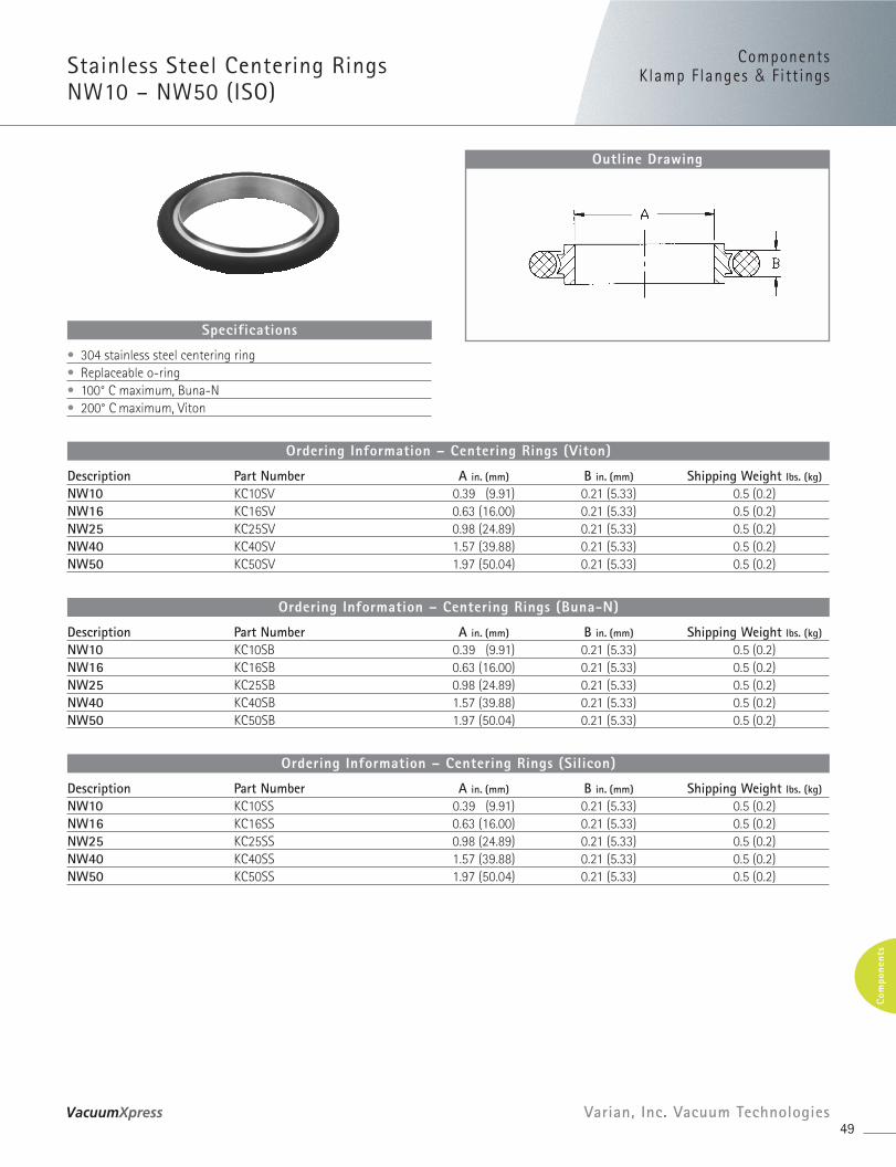
Stainless Steel Centering RingsNW10 – NW50 (ISO)
Description Part Number A in. (mm) B in. (mm) Shipping Weight lbs. (kg)
NW10 KC10SV 0.39 (9.91) 0.21 (5.33) 0.5 (0.2)NW16 KC16SV 0.63 (16.00) 0.21 (5.33) 0.5 (0.2)NW25 KC25SV 0.98 (24.89) 0.21 (5.33) 0.5 (0.2)NW40 KC40SV 1.57 (39.88) 0.21 (5.33) 0.5 (0.2)NW50 KC50SV 1.97 (50.04) 0.21 (5.33) 0.5 (0.2)
Ordering Information – Centering Rings (Viton)
Description Part Number A in. (mm) B in. (mm) Shipping Weight lbs. (kg)
NW10 KC10SB 0.39 (9.91) 0.21 (5.33) 0.5 (0.2)NW16 KC16SB 0.63 (16.00) 0.21 (5.33) 0.5 (0.2)NW25 KC25SB 0.98 (24.89) 0.21 (5.33) 0.5 (0.2)NW40 KC40SB 1.57 (39.88) 0.21 (5.33) 0.5 (0.2)NW50 KC50SB 1.97 (50.04) 0.21 (5.33) 0.5 (0.2)
Ordering Information – Centering Rings (Buna-N)
Description Part Number A in. (mm) B in. (mm) Shipping Weight lbs. (kg)
NW10 KC10SS 0.39 (9.91) 0.21 (5.33) 0.5 (0.2)NW16 KC16SS 0.63 (16.00) 0.21 (5.33) 0.5 (0.2)NW25 KC25SS 0.98 (24.89) 0.21 (5.33) 0.5 (0.2)NW40 KC40SS 1.57 (39.88) 0.21 (5.33) 0.5 (0.2)NW50 KC50SS 1.97 (50.04) 0.21 (5.33) 0.5 (0.2)
Ordering Information – Centering Rings (Silicon)
Outline Drawing
• 304 stainless steel centering ring• Replaceable o-ring• 100° C maximum, Buna-N• 200° C maximum, Viton
Specifications
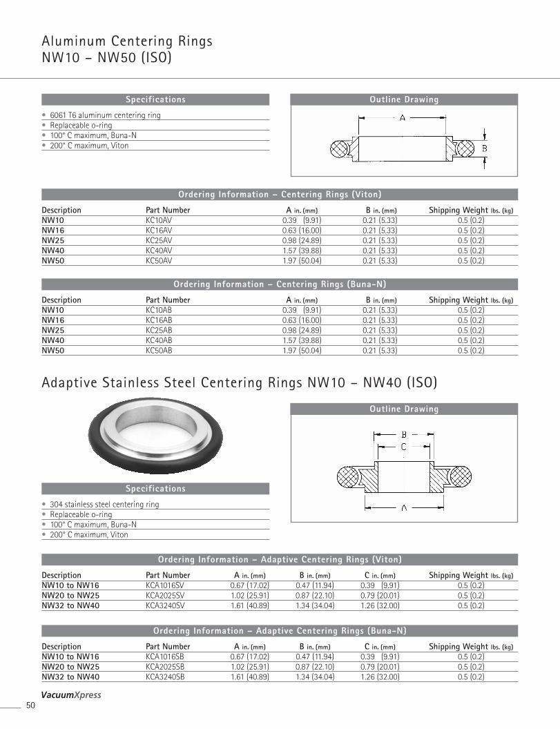
Aluminum Centering RingsNW10 – NW50 (ISO)
50
Description Part Number A in. (mm) B in. (mm) C in. (mm) Shipping Weight lbs. (kg)NW10 to NW16 KCA1016SV 0.67 (17.02) 0.47 (11.94) 0.39 (9.91) 0.5 (0.2)NW20 to NW25 KCA2025SV 1.02 (25.91) 0.87 (22.10) 0.79 (20.01) 0.5 (0.2)NW32 to NW40 KCA3240SV 1.61 (40.89) 1.34 (34.04) 1.26 (32.00) 0.5 (0.2)
Ordering Information – Adaptive Centering Rings (Viton)
Description Part Number A in. (mm) B in. (mm) C in. (mm) Shipping Weight lbs. (kg)NW10 to NW16 KCA1016SB 0.67 (17.02) 0.47 (11.94) 0.39 (9.91) 0.5 (0.2)NW20 to NW25 KCA2025SB 1.02 (25.91) 0.87 (22.10) 0.79 (20.01) 0.5 (0.2)NW32 to NW40 KCA3240SB 1.61 (40.89) 1.34 (34.04) 1.26 (32.00) 0.5 (0.2)
Ordering Information – Adaptive Centering Rings (Buna-N)
Outline Drawing
• 304 stainless steel centering ring• Replaceable o-ring• 100° C maximum, Buna-N• 200° C maximum, Viton
Specifications
Description Part Number A in. (mm) B in. (mm) Shipping Weight lbs. (kg)NW10 KC10AV 0.39 (9.91) 0.21 (5.33) 0.5 (0.2)NW16 KC16AV 0.63 (16.00) 0.21 (5.33) 0.5 (0.2)NW25 KC25AV 0.98 (24.89) 0.21 (5.33) 0.5 (0.2)NW40 KC40AV 1.57 (39.88) 0.21 (5.33) 0.5 (0.2)NW50 KC50AV 1.97 (50.04) 0.21 (5.33) 0.5 (0.2)
Ordering Information – Centering Rings (Viton)
Description Part Number A in. (mm) B in. (mm) Shipping Weight lbs. (kg)NW10 KC10AB 0.39 (9.91) 0.21 (5.33) 0.5 (0.2)NW16 KC16AB 0.63 (16.00) 0.21 (5.33) 0.5 (0.2)NW25 KC25AB 0.98 (24.89) 0.21 (5.33) 0.5 (0.2)NW40 KC40AB 1.57 (39.88) 0.21 (5.33) 0.5 (0.2)NW50 KC50AB 1.97 (50.04) 0.21 (5.33) 0.5 (0.2)
Ordering Information – Centering Rings (Buna-N)
• 6061 T6 aluminum centering ring• Replaceable o-ring• 100° C maximum, Buna-N• 200° C maximum, Viton
Specifications
Adaptive Stainless Steel Centering Rings NW10 – NW40 (ISO)
Outline Drawing
ComponentsKlamp F langes & Fitt ings
51Varian, Inc. Vacuum Technologies
Com
pone
nts
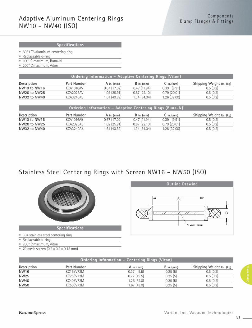
Description Part Number A in. (mm) B in. (mm) C in. (mm) Shipping Weight lbs. (kg)NW10 to NW16 KCA1016AV 0.67 (17.02) 0.47 (11.94) 0.39 (9.91) 0.5 (0.2)NW20 to NW25 KCA2025AV 1.02 (25.91) 0.87 (22.10) 0.79 (20.01) 0.5 (0.2)NW32 to NW40 KCA3240AV 1.61 (40.89) 1.34 (34.04) 1.26 (32.00) 0.5 (0.2)
Ordering Information – Adaptive Centering Rings (Viton)
Description Part Number A in. (mm) B in. (mm) C in. (mm) Shipping Weight lbs. (kg)NW10 to NW16 KCA1016AB 0.67 (17.02) 0.47 (11.94) 0.39 (9.91) 0.5 (0.2)NW20 to NW25 KCA2025AB 1.02 (25.91) 0.87 (22.10) 0.79 (20.01) 0.5 (0.2)NW32 to NW40 KCA3240AB 1.61 (40.89) 1.34 (34.04) 1.26 (32.00) 0.5 (0.2)
Ordering Information – Adaptive Centering Rings (Buna-N)
• 6061 T6 aluminum centering ring• Replaceable o-ring• 100° C maximum, Buna-N• 200° C maximum, Viton
Specifications
Adaptive Aluminum Centering Rings NW10 – NW40 (ISO)
Description Part Number A in. (mm) B in. (mm) Shipping Weight lbs. (kg)NW16 KC16SV72M 0.37 (9.5) 0.25 (5) 0.5 (0.2)NW25 KC25SV72M 0.77 (19.5) 0.25 (5) 0.5 (0.2)NW40 KC40SV72M 1.26 (32.0) 0.25 (5) 0.5 (0.2)NW50 KC50SV72M 1.67 (43.0) 0.25 (5) 0.5 (0.2)
Ordering Information – Centering Rings (Viton)
Outline Drawing
• 304 stainless steel centering ring• Replaceable o-ring• 200° C maximum, Viton• 70 mesh screen (0.2 x 0.2 x 0.15 mm)
Specifications
Stainless Steel Centering Rings with Screen NW16 – NW50 (ISO)
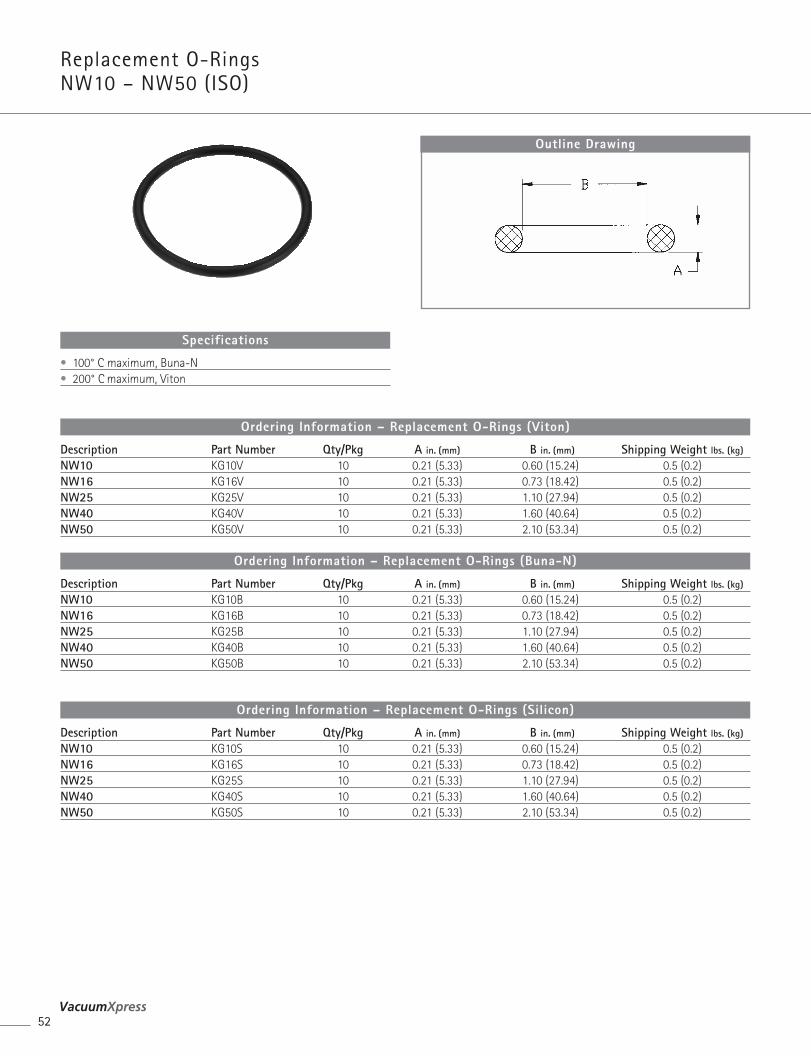
Replacement O-Rings NW10 – NW50 (ISO)
52
Description Part Number Qty/Pkg A in. (mm) B in. (mm) Shipping Weight lbs. (kg)
NW10 KG10V 10 0.21 (5.33) 0.60 (15.24) 0.5 (0.2)NW16 KG16V 10 0.21 (5.33) 0.73 (18.42) 0.5 (0.2)NW25 KG25V 10 0.21 (5.33) 1.10 (27.94) 0.5 (0.2)NW40 KG40V 10 0.21 (5.33) 1.60 (40.64) 0.5 (0.2)NW50 KG50V 10 0.21 (5.33) 2.10 (53.34) 0.5 (0.2)
Ordering Information – Replacement O-Rings (Viton)
Description Part Number Qty/Pkg A in. (mm) B in. (mm) Shipping Weight lbs. (kg)
NW10 KG10B 10 0.21 (5.33) 0.60 (15.24) 0.5 (0.2)NW16 KG16B 10 0.21 (5.33) 0.73 (18.42) 0.5 (0.2)NW25 KG25B 10 0.21 (5.33) 1.10 (27.94) 0.5 (0.2)NW40 KG40B 10 0.21 (5.33) 1.60 (40.64) 0.5 (0.2)NW50 KG50B 10 0.21 (5.33) 2.10 (53.34) 0.5 (0.2)
Ordering Information – Replacement O-Rings (Buna-N)
Description Part Number Qty/Pkg A in. (mm) B in. (mm) Shipping Weight lbs. (kg)
NW10 KG10S 10 0.21 (5.33) 0.60 (15.24) 0.5 (0.2)NW16 KG16S 10 0.21 (5.33) 0.73 (18.42) 0.5 (0.2)NW25 KG25S 10 0.21 (5.33) 1.10 (27.94) 0.5 (0.2)NW40 KG40S 10 0.21 (5.33) 1.60 (40.64) 0.5 (0.2)NW50 KG50S 10 0.21 (5.33) 2.10 (53.34) 0.5 (0.2)
Ordering Information – Replacement O-Rings (Silicon)
Outline Drawing
• 100° C maximum, Buna-N• 200° C maximum, Viton
Specifications
ComponentsKlamp F langes & Fitt ings
53Varian, Inc. Vacuum Technologies
Com
pone
nts
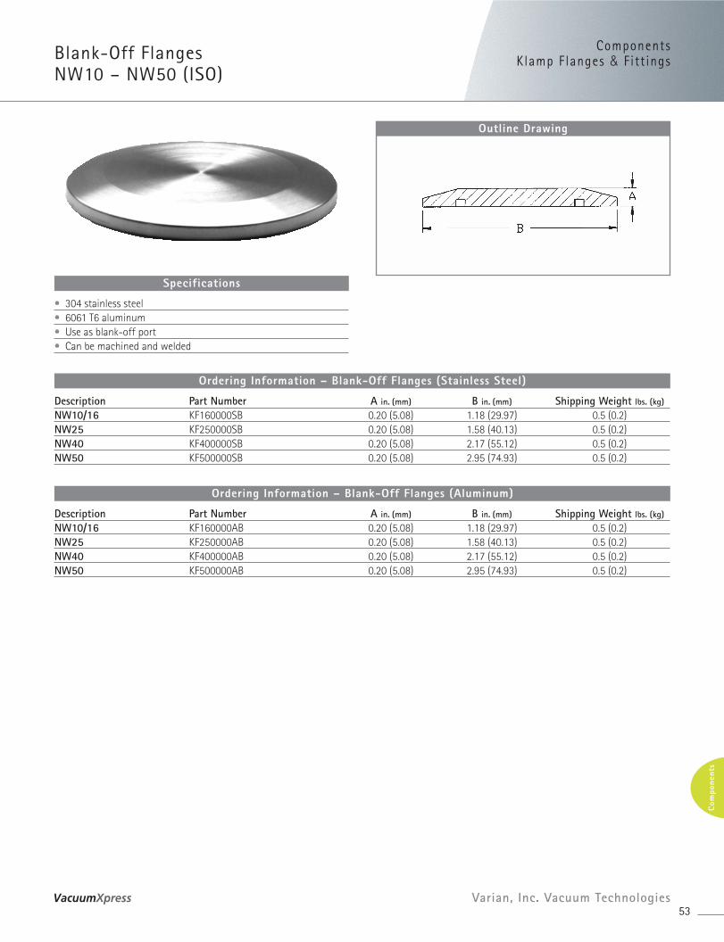
Blank-Off Flanges NW10 – NW50 (ISO)
Description Part Number A in. (mm) B in. (mm) Shipping Weight lbs. (kg)
NW10/16 KF160000SB 0.20 (5.08) 1.18 (29.97) 0.5 (0.2)NW25 KF250000SB 0.20 (5.08) 1.58 (40.13) 0.5 (0.2)NW40 KF400000SB 0.20 (5.08) 2.17 (55.12) 0.5 (0.2)NW50 KF500000SB 0.20 (5.08) 2.95 (74.93) 0.5 (0.2)
Ordering Information – Blank-Off Flanges (Stainless Steel)
Description Part Number A in. (mm) B in. (mm) Shipping Weight lbs. (kg)
NW10/16 KF160000AB 0.20 (5.08) 1.18 (29.97) 0.5 (0.2)NW25 KF250000AB 0.20 (5.08) 1.58 (40.13) 0.5 (0.2)NW40 KF400000AB 0.20 (5.08) 2.17 (55.12) 0.5 (0.2)NW50 KF500000AB 0.20 (5.08) 2.95 (74.93) 0.5 (0.2)
Ordering Information – Blank-Off Flanges (Aluminum)
Outline Drawing
• 304 stainless steel• 6061 T6 aluminum• Use as blank-off port• Can be machined and welded
Specifications
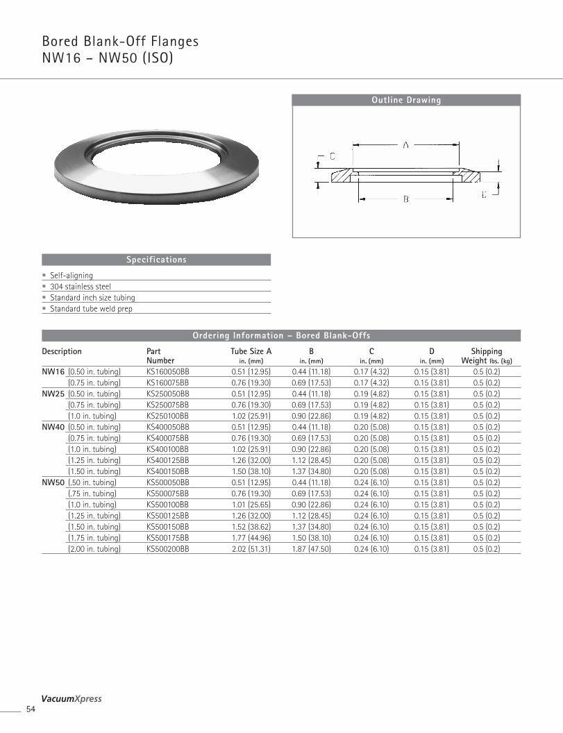
Bored Blank-Off Flanges NW16 – NW50 (ISO)
54
Description Part Tube Size A B C D ShippingNumber in. (mm) in. (mm) in. (mm) in. (mm) Weight lbs. (kg)
NW16 (0.50 in. tubing) KS160050BB 0.51 (12.95) 0.44 (11.18) 0.17 (4.32) 0.15 (3.81) 0.5 (0.2)(0.75 in. tubing) KS160075BB 0.76 (19.30) 0.69 (17.53) 0.17 (4.32) 0.15 (3.81) 0.5 (0.2)
NW25 (0.50 in. tubing) KS250050BB 0.51 (12.95) 0.44 (11.18) 0.19 (4.82) 0.15 (3.81) 0.5 (0.2)(0.75 in. tubing) KS250075BB 0.76 (19.30) 0.69 (17.53) 0.19 (4.82) 0.15 (3.81) 0.5 (0.2)(1.0 in. tubing) KS250100BB 1.02 (25.91) 0.90 (22.86) 0.19 (4.82) 0.15 (3.81) 0.5 (0.2)
NW40 (0.50 in. tubing) KS400050BB 0.51 (12.95) 0.44 (11.18) 0.20 (5.08) 0.15 (3.81) 0.5 (0.2)(0.75 in. tubing) KS400075BB 0.76 (19.30) 0.69 (17.53) 0.20 (5.08) 0.15 (3.81) 0.5 (0.2)(1.0 in. tubing) KS400100BB 1.02 (25.91) 0.90 (22.86) 0.20 (5.08) 0.15 (3.81) 0.5 (0.2)(1.25 in. tubing) KS400125BB 1.26 (32.00) 1.12 (28.45) 0.20 (5.08) 0.15 (3.81) 0.5 (0.2)(1.50 in. tubing) KS400150BB 1.50 (38.10) 1.37 (34.80) 0.20 (5.08) 0.15 (3.81) 0.5 (0.2)
NW50 (.50 in. tubing) KS500050BB 0.51 (12.95) 0.44 (11.18) 0.24 (6.10) 0.15 (3.81) 0.5 (0.2)(.75 in. tubing) KS500075BB 0.76 (19.30) 0.69 (17.53) 0.24 (6.10) 0.15 (3.81) 0.5 (0.2)(1.0 in. tubing) KS500100BB 1.01 (25.65) 0.90 (22.86) 0.24 (6.10) 0.15 (3.81) 0.5 (0.2)(1.25 in. tubing) KS500125BB 1.26 (32.00) 1.12 (28.45) 0.24 (6.10) 0.15 (3.81) 0.5 (0.2)(1.50 in. tubing) KS500150BB 1.52 (38.62) 1.37 (34.80) 0.24 (6.10) 0.15 (3.81) 0.5 (0.2)(1.75 in. tubing) KS500175BB 1.77 (44.96) 1.50 (38.10) 0.24 (6.10) 0.15 (3.81) 0.5 (0.2)(2.00 in. tubing) KS500200BB 2.02 (51.31) 1.87 (47.50) 0.24 (6.10) 0.15 (3.81) 0.5 (0.2)
Ordering Information – Bored Blank-Offs
Outline Drawing
• Self-aligning• 304 stainless steel• Standard inch size tubing• Standard tube weld prep
Specifications
ComponentsKlamp F langes & Fitt ings
55Varian, Inc. Vacuum Technologies
Com
pone
nts
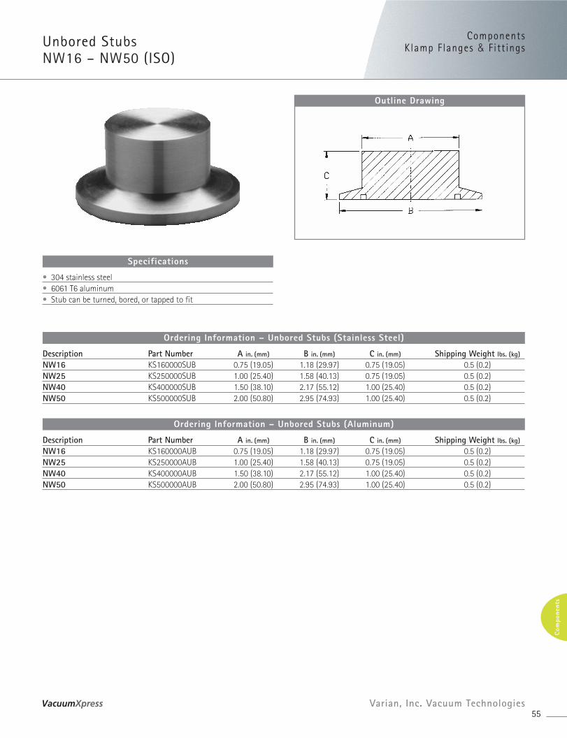
Unbored Stubs NW16 – NW50 (ISO)
Description Part Number A in. (mm) B in. (mm) C in. (mm) Shipping Weight lbs. (kg)
NW16 KS160000SUB 0.75 (19.05) 1.18 (29.97) 0.75 (19.05) 0.5 (0.2)NW25 KS250000SUB 1.00 (25.40) 1.58 (40.13) 0.75 (19.05) 0.5 (0.2)NW40 KS400000SUB 1.50 (38.10) 2.17 (55.12) 1.00 (25.40) 0.5 (0.2)NW50 KS500000SUB 2.00 (50.80) 2.95 (74.93) 1.00 (25.40) 0.5 (0.2)
Ordering Information – Unbored Stubs (Stainless Steel)
Description Part Number A in. (mm) B in. (mm) C in. (mm) Shipping Weight lbs. (kg)
NW16 KS160000AUB 0.75 (19.05) 1.18 (29.97) 0.75 (19.05) 0.5 (0.2)NW25 KS250000AUB 1.00 (25.40) 1.58 (40.13) 0.75 (19.05) 0.5 (0.2)NW40 KS400000AUB 1.50 (38.10) 2.17 (55.12) 1.00 (25.40) 0.5 (0.2)NW50 KS500000AUB 2.00 (50.80) 2.95 (74.93) 1.00 (25.40) 0.5 (0.2)
Ordering Information – Unbored Stubs (Aluminum)
Outline Drawing
• 304 stainless steel• 6061 T6 aluminum• Stub can be turned, bored, or tapped to fit
Specifications
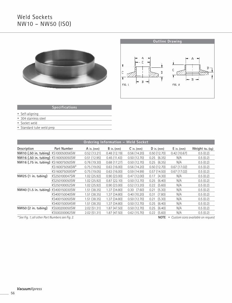
Weld Sockets NW10 – NW50 (ISO)
56
Outline Drawing
• Self-aligning• 304 stainless steel• Socket weld• Standard tube weld prep
Specifications
Description Part Number A in. (mm) B in. (mm) C in. (mm) D in. (mm) E in. (mm) Weight lbs. (kg)
NW10 (.50 in. tubing) KS100050056SW 0.52 (13.21) 0.48 (12.19) 0.56 (14.20) 0.50 (12.70) 0.42 (10.67) 0.5 (0.2)NW16 (.50 in. tubing) KS160050050SW 0.51 (12.95) 0.45 (11.43) 0.50 (12.70) 0.25 (6.35) N/A 0.5 (0.2)NW16 (.75 in. tubing) KS160075050SW 0.76 (19.30) 0.68 (17.27) 0.50 (12.70) 0.25 (6.35) N/A 0.5 (0.2)
KS160075056SW* 0.75 (19.05) 0.63 (16.00) 0.56 (14.20) 0.50 (12.70) 0.67 (17.02) 0.5 (0.2)KS160075059SW* 0.75 (19.05) 0.63 (16.00) 0.59 (14.99) 0.57 (14.50) 0.67 (17.02) 0.5 (0.2)
NW25 (1 in. tubing) KS250100047SW 1.02 (25.92) 0.90 (23.00) 0.47 (12.00) 0.17 (4.30) N/A 0.5 (0.2)KS250100050SW 1.02 (25.92) 0.87 (22.10) 0.50 (12.70) 0.25 (6.40) N/A 0.5 (0.2)KS250100052SW 1.02 (25.92) 0.90 (23.00) 0.52 (13.20) 0.22 (5.60) N/A 0.5 (0.2)
NW40 (1.5 in. tubing) KS400150030SW 1.51 (38.35) 1.37 (34.80) 0.30 (7.60) 0.21 (5.30) N/A 0.5 (0.2)KS400150040SW 1.51 (38.35) 1.37 (34.80) 0.40 (10.20) 0.31 (7.80) N/A 0.5 (0.2)KS400150050SW 1.51 (38.35) 1.37 (34.80) 0.50 (12.70) 0.21 (5.30) N/A 0.5 (0.2)KS40015005ASW 1.51 (38.35) 1.37 (34.80) 0.50 (12.70) 0.25 (6.40) N/A 0.5 (0.2)
NW50 (2 in. tubing) KS500200050SW 2.02 (51.31) 1.87 (47.50) 0.50 (12.70) 0.25 (6.40) N/A 0.5 (0.2)KS500200062SW 2.02 (51.31) 1.87 (47.50) 0.62 (15.70) 0.22 (5.60) N/A 0.5 (0.2)
* See Fig. 1; all other Part Numbers see Fig. 2. NOTE • Custom sizes available on request
Ordering Information – Weld Socket
ComponentsKlamp F langes & Fitt ings
57Varian, Inc. Vacuum Technologies
Com
pone
nts
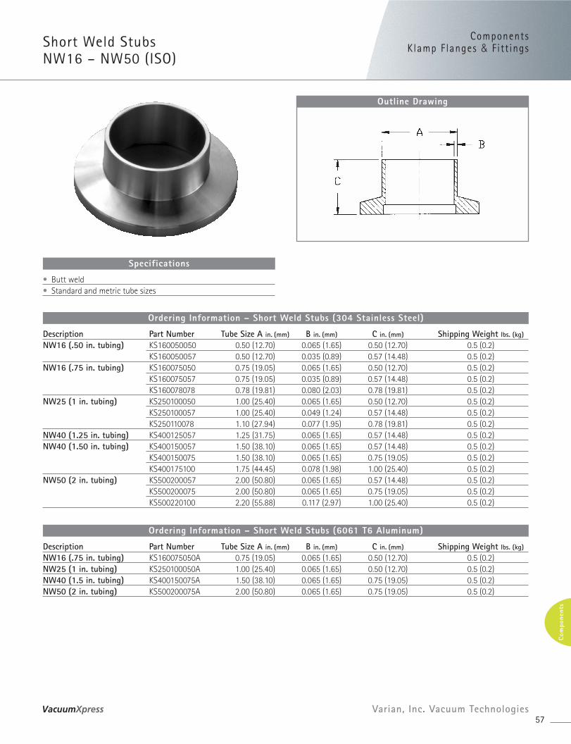
Short Weld Stubs NW16 – NW50 (ISO)
Description Part Number Tube Size A in. (mm) B in. (mm) C in. (mm) Shipping Weight lbs. (kg)
NW16 (.50 in. tubing) KS160050050 0.50 (12.70) 0.065 (1.65) 0.50 (12.70) 0.5 (0.2)KS160050057 0.50 (12.70) 0.035 (0.89) 0.57 (14.48) 0.5 (0.2)
NW16 (.75 in. tubing) KS160075050 0.75 (19.05) 0.065 (1.65) 0.50 (12.70) 0.5 (0.2)KS160075057 0.75 (19.05) 0.035 (0.89) 0.57 (14.48) 0.5 (0.2)KS160078078 0.78 (19.81) 0.080 (2.03) 0.78 (19.81) 0.5 (0.2)
NW25 (1 in. tubing) KS250100050 1.00 (25.40) 0.065 (1.65) 0.50 (12.70) 0.5 (0.2)KS250100057 1.00 (25.40) 0.049 (1.24) 0.57 (14.48) 0.5 (0.2)KS250110078 1.10 (27.94) 0.077 (1.95) 0.78 (19.81) 0.5 (0.2)
NW40 (1.25 in. tubing) KS400125057 1.25 (31.75) 0.065 (1.65) 0.57 (14.48) 0.5 (0.2)NW40 (1.50 in. tubing) KS400150057 1.50 (38.10) 0.065 (1.65) 0.57 (14.48) 0.5 (0.2)
KS400150075 1.50 (38.10) 0.065 (1.65) 0.75 (19.05) 0.5 (0.2)KS400175100 1.75 (44.45) 0.078 (1.98) 1.00 (25.40) 0.5 (0.2)
NW50 (2 in. tubing) KS500200057 2.00 (50.80) 0.065 (1.65) 0.57 (14.48) 0.5 (0.2)KS500200075 2.00 (50.80) 0.065 (1.65) 0.75 (19.05) 0.5 (0.2)KS500220100 2.20 (55.88) 0.117 (2.97) 1.00 (25.40) 0.5 (0.2)
Ordering Information – Short Weld Stubs (304 Stainless Steel)
Description Part Number Tube Size A in. (mm) B in. (mm) C in. (mm) Shipping Weight lbs. (kg)
NW16 (.75 in. tubing) KS160075050A 0.75 (19.05) 0.065 (1.65) 0.50 (12.70) 0.5 (0.2)NW25 (1 in. tubing) KS250100050A 1.00 (25.40) 0.065 (1.65) 0.50 (12.70) 0.5 (0.2)NW40 (1.5 in. tubing) KS400150075A 1.50 (38.10) 0.065 (1.65) 0.75 (19.05) 0.5 (0.2)NW50 (2 in. tubing) KS500200075A 2.00 (50.80) 0.065 (1.65) 0.75 (19.05) 0.5 (0.2)
Ordering Information – Short Weld Stubs (6061 T6 Aluminum)
Outline Drawing
• Butt weld• Standard and metric tube sizes
Specifications
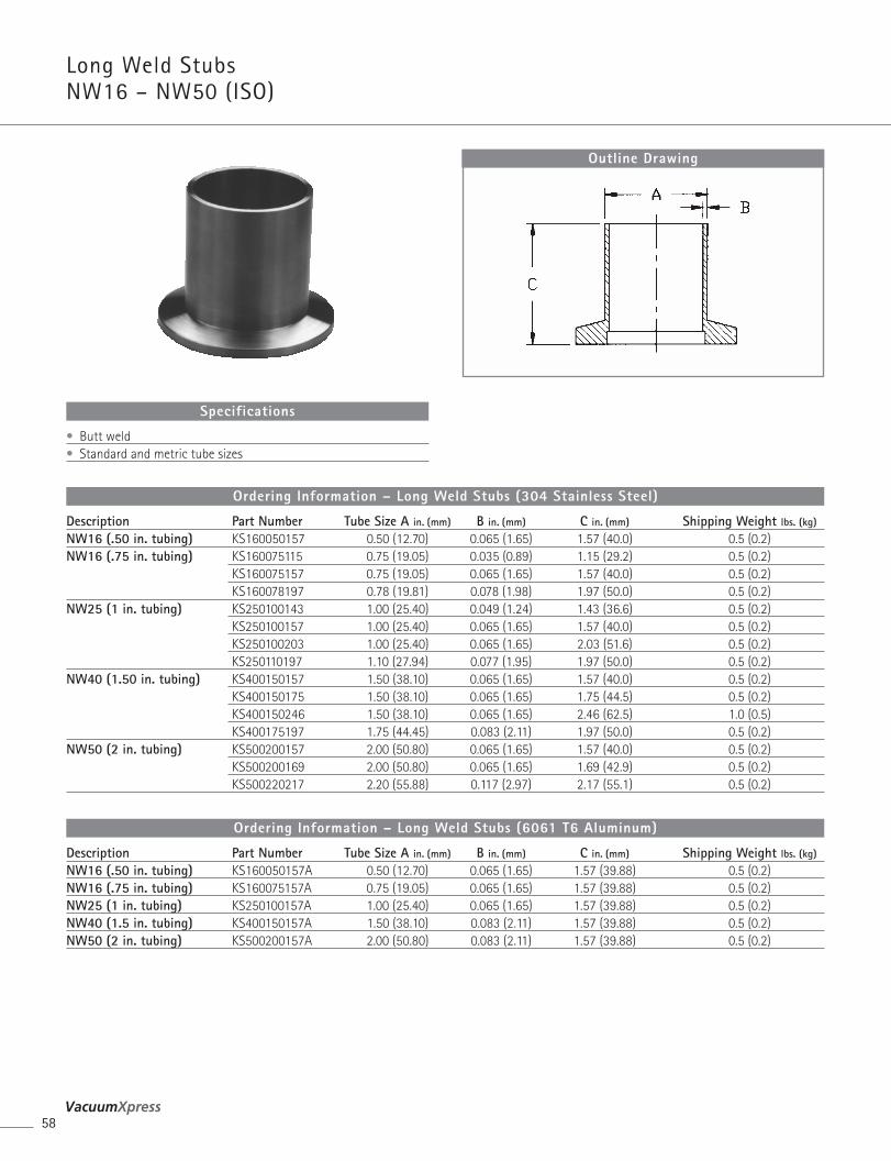
Long Weld Stubs NW16 – NW50 (ISO)
58
Description Part Number Tube Size A in. (mm) B in. (mm) C in. (mm) Shipping Weight lbs. (kg)
NW16 (.50 in. tubing) KS160050157 0.50 (12.70) 0.065 (1.65) 1.57 (40.0) 0.5 (0.2)NW16 (.75 in. tubing) KS160075115 0.75 (19.05) 0.035 (0.89) 1.15 (29.2) 0.5 (0.2)
KS160075157 0.75 (19.05) 0.065 (1.65) 1.57 (40.0) 0.5 (0.2)KS160078197 0.78 (19.81) 0.078 (1.98) 1.97 (50.0) 0.5 (0.2)
NW25 (1 in. tubing) KS250100143 1.00 (25.40) 0.049 (1.24) 1.43 (36.6) 0.5 (0.2)KS250100157 1.00 (25.40) 0.065 (1.65) 1.57 (40.0) 0.5 (0.2)KS250100203 1.00 (25.40) 0.065 (1.65) 2.03 (51.6) 0.5 (0.2)KS250110197 1.10 (27.94) 0.077 (1.95) 1.97 (50.0) 0.5 (0.2)
NW40 (1.50 in. tubing) KS400150157 1.50 (38.10) 0.065 (1.65) 1.57 (40.0) 0.5 (0.2)KS400150175 1.50 (38.10) 0.065 (1.65) 1.75 (44.5) 0.5 (0.2)KS400150246 1.50 (38.10) 0.065 (1.65) 2.46 (62.5) 1.0 (0.5)KS400175197 1.75 (44.45) 0.083 (2.11) 1.97 (50.0) 0.5 (0.2)
NW50 (2 in. tubing) KS500200157 2.00 (50.80) 0.065 (1.65) 1.57 (40.0) 0.5 (0.2)KS500200169 2.00 (50.80) 0.065 (1.65) 1.69 (42.9) 0.5 (0.2)KS500220217 2.20 (55.88) 0.117 (2.97) 2.17 (55.1) 0.5 (0.2)
Ordering Information – Long Weld Stubs (304 Stainless Steel)
Description Part Number Tube Size A in. (mm) B in. (mm) C in. (mm) Shipping Weight lbs. (kg)
NW16 (.50 in. tubing) KS160050157A 0.50 (12.70) 0.065 (1.65) 1.57 (39.88) 0.5 (0.2)NW16 (.75 in. tubing) KS160075157A 0.75 (19.05) 0.065 (1.65) 1.57 (39.88) 0.5 (0.2)NW25 (1 in. tubing) KS250100157A 1.00 (25.40) 0.065 (1.65) 1.57 (39.88) 0.5 (0.2)NW40 (1.5 in. tubing) KS400150157A 1.50 (38.10) 0.083 (2.11) 1.57 (39.88) 0.5 (0.2)NW50 (2 in. tubing) KS500200157A 2.00 (50.80) 0.083 (2.11) 1.57 (39.88) 0.5 (0.2)
Ordering Information – Long Weld Stubs (6061 T6 Aluminum)
Outline Drawing
• Butt weld• Standard and metric tube sizes
Specifications
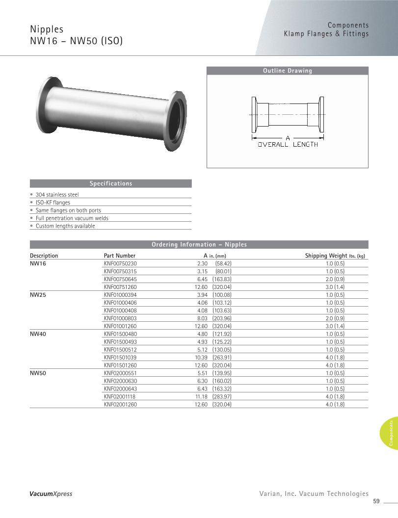
ComponentsKlamp F langes & Fitt ings
59Varian, Inc. Vacuum Technologies
Com
pone
nts
Nipples NW16 – NW50 (ISO)
Description Part Number A in. (mm) Shipping Weight lbs. (kg)
NW16 KNF00750230 2.30 (58.42) 1.0 (0.5)KNF00750315 3.15 (80.01) 1.0 (0.5)KNF00750645 6.45 (163.83) 2.0 (0.9)KNF00751260 12.60 (320.04) 3.0 (1.4)
NW25 KNF01000394 3.94 (100.08) 1.0 (0.5)KNF01000406 4.06 (103.12) 1.0 (0.5)KNF01000408 4.08 (103.63) 1.0 (0.5)KNF01000803 8.03 (203.96) 2.0 (0.9)KNF01001260 12.60 (320.04) 3.0 (1.4)
NW40 KNF01500480 4.80 (121.92) 1.0 (0.5)KNF01500493 4.93 (125.22) 1.0 (0.5)KNF01500512 5.12 (130.05) 1.0 (0.5)KNF01501039 10.39 (263.91) 4.0 (1.8)KNF01501260 12.60 (320.04) 4.0 (1.8)
NW50 KNF02000551 5.51 (139.95) 1.0 (0.5)KNF02000630 6.30 (160.02) 1.0 (0.5)KNF02000643 6.43 (163.32) 1.0 (0.5)KNF02001118 11.18 (283.97) 4.0 (1.8)KNF02001260 12.60 (320.04) 4.0 (1.8)
Ordering Information – Nipples
Outline Drawing
• 304 stainless steel• ISO-KF flanges• Same flanges on both ports• Full penetration vacuum welds• Custom lengths available
Specifications
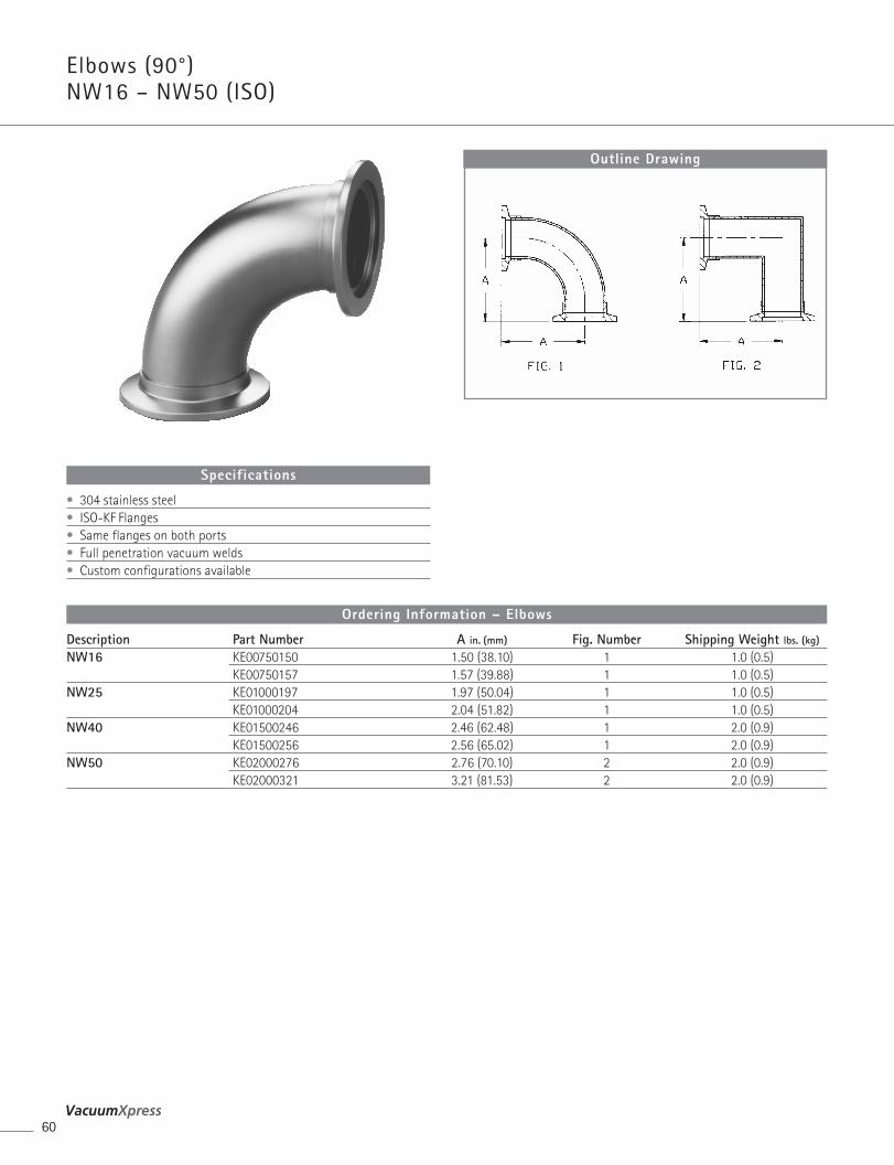
Elbows (90°) NW16 – NW50 (ISO)
60
Description Part Number A in. (mm) Fig. Number Shipping Weight lbs. (kg)
NW16 KE00750150 1.50 (38.10) 1 1.0 (0.5)KE00750157 1.57 (39.88) 1 1.0 (0.5)
NW25 KE01000197 1.97 (50.04) 1 1.0 (0.5)KE01000204 2.04 (51.82) 1 1.0 (0.5)
NW40 KE01500246 2.46 (62.48) 1 2.0 (0.9)KE01500256 2.56 (65.02) 1 2.0 (0.9)
NW50 KE02000276 2.76 (70.10) 2 2.0 (0.9)KE02000321 3.21 (81.53) 2 2.0 (0.9)
Ordering Information – Elbows
Outline Drawing
• 304 stainless steel• ISO-KF Flanges• Same flanges on both ports• Full penetration vacuum welds• Custom configurations available
Specifications
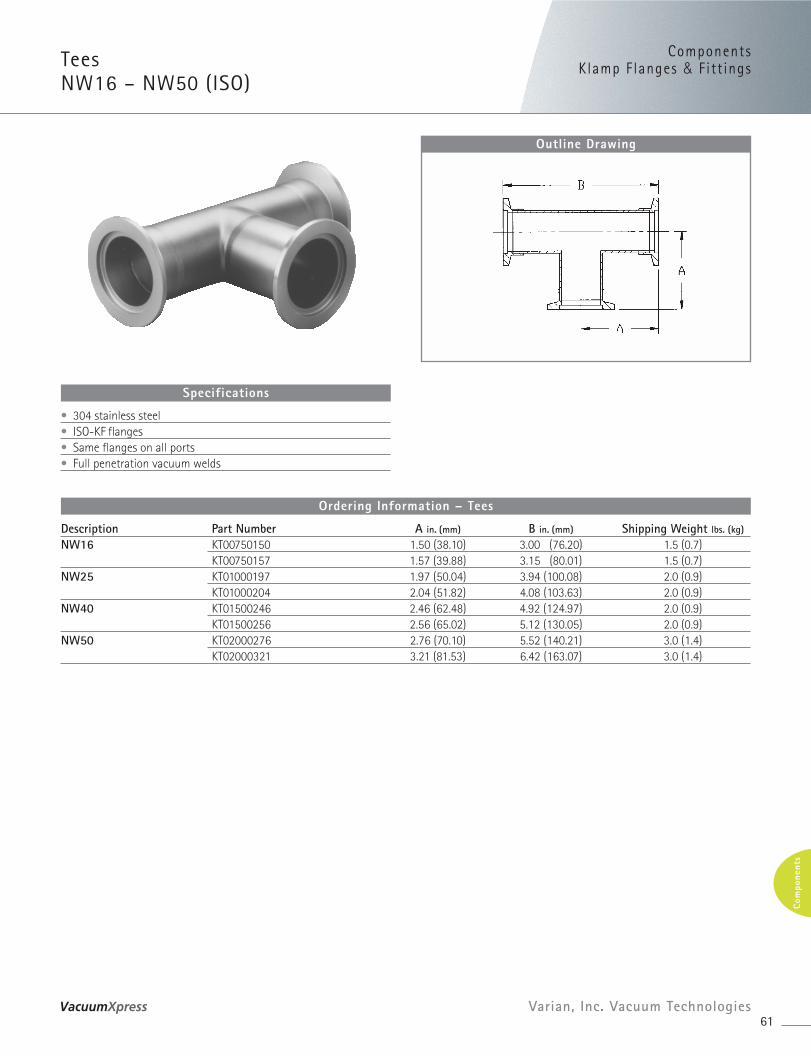
ComponentsKlamp F langes & Fitt ings
61Varian, Inc. Vacuum Technologies
Com
pone
nts
Tees NW16 – NW50 (ISO)
Description Part Number A in. (mm) B in. (mm) Shipping Weight lbs. (kg)
NW16 KT00750150 1.50 (38.10) 3.00 (76.20) 1.5 (0.7)KT00750157 1.57 (39.88) 3.15 (80.01) 1.5 (0.7)
NW25 KT01000197 1.97 (50.04) 3.94 (100.08) 2.0 (0.9)KT01000204 2.04 (51.82) 4.08 (103.63) 2.0 (0.9)
NW40 KT01500246 2.46 (62.48) 4.92 (124.97) 2.0 (0.9)KT01500256 2.56 (65.02) 5.12 (130.05) 2.0 (0.9)
NW50 KT02000276 2.76 (70.10) 5.52 (140.21) 3.0 (1.4)KT02000321 3.21 (81.53) 6.42 (163.07) 3.0 (1.4)
Ordering Information – Tees
Outline Drawing
• 304 stainless steel• ISO-KF flanges• Same flanges on all ports • Full penetration vacuum welds
Specifications
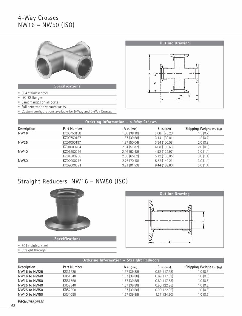
4-Way Crosses NW16 – NW50 (ISO)
62
Description Part Number A in. (mm) B in. (mm) Shipping Weight lbs. (kg)NW16 KC00750150 1.50 (38.10) 3.00 (76.20) 1.5 (0.7)
KC00750157 1.57 (39.88) 3.14 (80.01) 1.5 (0.7)NW25 KC01000197 1.97 (50.04) 3.94 (100.08) 2.0 (0.9)
KC01000204 2.04 (51.82) 4.08 (103.63) 2.0 (0.9)NW40 KC01500246 2.46 (62.48) 4.92 (124.97) 3.0 (1.4)
KC01500256 2.56 (65.02) 5.12 (130.05) 3.0 (1.4)NW50 KC02000276 2.76 (70.10) 5.52 (140.21) 3.0 (1.4)
KC02000321 3.21 (81.53) 6.44 (163.60) 3.0 (1.4)
Ordering Information – 4-Way Crosses
Outline Drawing
• 304 stainless steel• ISO-KF flanges• Same flanges on all ports• Full penetration vacuum welds• Custom configurations available for 5-Way and 6-Way Crosses
Specifications
Straight Reducers NW16 – NW50 (ISO)
Description Part Number A in. (mm) B in. (mm) Shipping Weight lbs. (kg)NW16 to NW25 KRS1625 1.57 (39.88) 0.69 (17.53) 1.0 (0.5)NW16 to NW40 KRS1640 1.57 (39.88) 0.69 (17.53) 1.0 (0.5)NW16 to NW50 KRS1650 1.57 (39.88) 0.69 (17.53) 1.0 (0.5)NW25 to NW40 KRS2540 1.57 (39.88) 0.90 (22.86) 1.0 (0.5)NW25 to NW50 KRS2550 1.57 (39.88) 0.90 (22.86) 1.0 (0.5)NW40 to NW50 KRS4050 1.57 (39.88) 1.37 (34.80) 1.0 (0.5)
Ordering Information – Straight Reducers
Outline Drawing
• 304 stainless steel• Straight through
Specifications
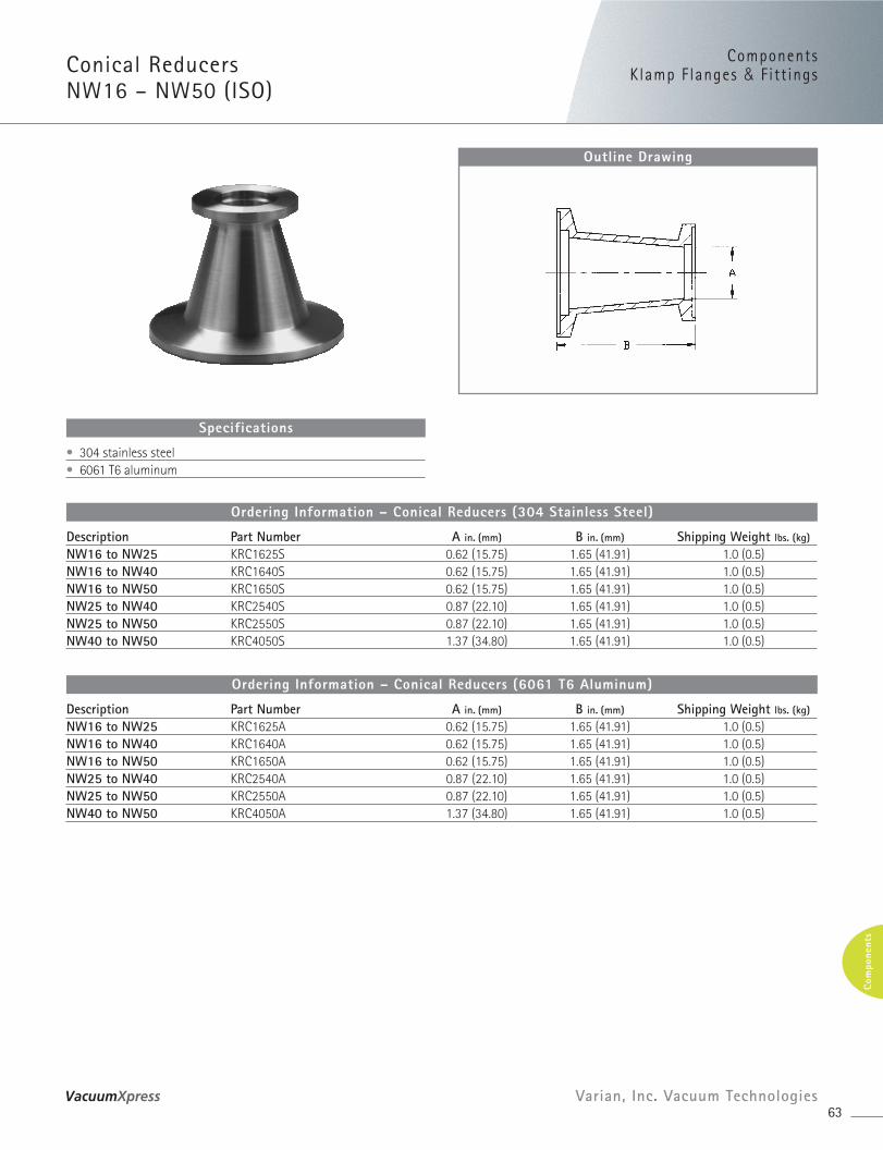
ComponentsKlamp F langes & Fitt ings
63Varian, Inc. Vacuum Technologies
Com
pone
nts
Conical Reducers NW16 – NW50 (ISO)
Description Part Number A in. (mm) B in. (mm) Shipping Weight lbs. (kg)
NW16 to NW25 KRC1625S 0.62 (15.75) 1.65 (41.91) 1.0 (0.5)NW16 to NW40 KRC1640S 0.62 (15.75) 1.65 (41.91) 1.0 (0.5)NW16 to NW50 KRC1650S 0.62 (15.75) 1.65 (41.91) 1.0 (0.5)NW25 to NW40 KRC2540S 0.87 (22.10) 1.65 (41.91) 1.0 (0.5)NW25 to NW50 KRC2550S 0.87 (22.10) 1.65 (41.91) 1.0 (0.5)NW40 to NW50 KRC4050S 1.37 (34.80) 1.65 (41.91) 1.0 (0.5)
Ordering Information – Conical Reducers (304 Stainless Steel)
Description Part Number A in. (mm) B in. (mm) Shipping Weight lbs. (kg)
NW16 to NW25 KRC1625A 0.62 (15.75) 1.65 (41.91) 1.0 (0.5)NW16 to NW40 KRC1640A 0.62 (15.75) 1.65 (41.91) 1.0 (0.5)NW16 to NW50 KRC1650A 0.62 (15.75) 1.65 (41.91) 1.0 (0.5)NW25 to NW40 KRC2540A 0.87 (22.10) 1.65 (41.91) 1.0 (0.5)NW25 to NW50 KRC2550A 0.87 (22.10) 1.65 (41.91) 1.0 (0.5)NW40 to NW50 KRC4050A 1.37 (34.80) 1.65 (41.91) 1.0 (0.5)
Ordering Information – Conical Reducers (6061 T6 Aluminum)
Outline Drawing
• 304 stainless steel• 6061 T6 aluminum
Specifications
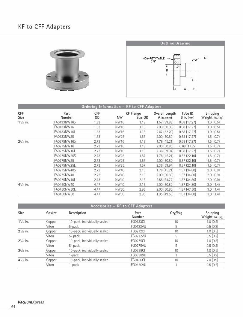
KF to CFF Adapters
64
CFF Part CFF KF Flange Overall Length Tube ID ShippingSize Number OD NW Size OD A in. (mm) B in. (mm) Weight lbs. (kg)
11⁄3 in. FA0133NW16S 1.33 NW16 1.18 1.57 (39.88) 0.68 (17.27) 1.0 (0.5)FA0133NW16 1.33 NW16 1.18 2.00 (50.80) 0.68 (17.27) 1.0 (0.5)FA0133NW16L 1.33 NW16 1.18 2.07 (52.70) 0.68 (17.27) 1.0 (0.5)FA0133NW25 1.33 NW25 1.57 2.00 (50.80) 0.68 (17.27) 1.5 (0.7)
23⁄4 in. FA0275NW16S 2.73 NW16 1.18 1.78 (45.21) 0.68 (17.27) 1.5 (0.7)FA0275NW16 2.73 NW16 1.18 2.00 (50.80) 0.68 (17.27) 1.5 (0.7)FA0275NW16L 2.73 NW16 1.18 2.36 (59.94) 0.68 (17.27) 1.5 (0.7)FA0275NW25S 2.73 NW25 1.57 1.78 (45.21) 0.87 (22.10) 1.5 (0.7)FA0275NW25 2.73 NW25 1.57 2.00 (50.80) 0.87 (22.10) 1.5 (0.7)FA0275NW25L 2.73 NW25 1.57 2.36 (59.94) 0.87 (22.10) 1.5 (0.7)FA0275NW40S 2.73 NW40 2.16 1.78 (45.21) 1.37 (34.80) 2.0 (0.9)FA0275NW40 2.73 NW40 2.16 2.00 (50.80) 1.37 (34.80) 2.0 (0.9)FA0275NW40L 2.73 NW40 2.16 2.55 (64.77) 1.37 (34.80) 2.0 (0.9)
41⁄2 in. FA0450NW40 4.47 NW40 2.16 2.00 (50.80) 1.37 (34.80) 3.0 (1.4)FA0450NW50L 4.47 NW50 2.95 2.00 (50.80) 1.87 (47.50) 3.0 (1.4)FA0450NW50 4.47 NW50 2.95 1.95 (49.53) 1.87 (34.80) 3.0 (1.4)
Ordering Information – KF to CFF Adapters
Outline Drawing
Size Gasket Description Part Qty/Pkg ShippingNumber Weight lbs. (kg)
11⁄3 in. Copper 10-pack, individually sealed FG0133CI 10 1.0 (0.5) Viton 5-pack FG0133VU 5 0.5 (0.2)
21⁄8 in. Copper 10-pack, individually sealed FG0212CI 10 1.0 (0.5)Viton 5- pack FG0212VU 5 0.5 (0.2)
23⁄4 in. Copper 10-pack, individually sealed FG0275CI 10 1.0 (0.5)Viton 5- pack FG0275VU 5 0.5 (0.2)
33⁄8 in. Copper 10-pack, individually sealed FG0338CI 10 1.0 (0.5)Viton 1-pack FG0338VU 1 0.5 (0.2)
41⁄2 in. Copper 10-pack, individually sealed FG0450CI 10 2.0 (0.9)Viton 1-pack FG0450VU 1 0.5 (0.2)
Accessories – KF to CFF Adapters
ComponentsKlamp F langes & Fitt ings
65Varian, Inc. Vacuum Technologies
Com
pone
nts
Size Nut and Bolt Sets Hex Head 12-Point Bolt Qty/Pkg ShippingPart Number Part Number Weight lbs. (kg)
11⁄3 in. Clear hole flanges N/A FB0133C** 25 0.5 (0.2)Tapped hole flanges N/A FB0133T** 25 0.5 (0.2)
21⁄8 in. Clear hole flanges FB0275C06 FB0275C12 25 1.0 (0.5)Tapped hole flanges FB0275T06 FB0275T12 25 1.0 (0.5)
23⁄4 in. Clear hole flanges FB0275C06 FB0275C12 25 1.0 (0.5)Tapped hole flanges FB0275T06 FB0275T12 25 1.0 (0.5)
33⁄8 in. Clear hole flanges FB0338C06 FB0338C12 25 2.0 (0.9)Tapped hole flanges FB0450T06 FB0450T12 25 2.0 (0.9)
41⁄2 in. Clear hole flanges FB0450C06 FB0450C12 25 2.0 (0.9)Tapped hole flanges FB0450T06 FB0450T12 25 2.0 (0.9)
* Includes nuts, washers, and bolts**Only available in Socket Head
Accessories – KF to CFF Adapters
Size Description Part Qty/Pkg ShippingNumber Weight lbs. (kg)
NW16 Viton Centering Ring KC16SV 1 0.5 (0.2)NW25 Viton Centering Ring KC25SV 1 0.5 (0.2)NW40 Viton Centering Ring KC40SV 1 0.5 (0.2)NW50 Viton Centering Ring KC50SV 1 0.5 (0.2)NW16 KF Clamp KQ16AR 1 0.5 (0.2)NW25 KF Clamp KQ25AR 1 0.5 (0.2)NW40 KF Clamp KQ40AR 1 1.0 (0.5)NW50 KF Clamp KQ50AR 1 1.0 (0.5)NOTE • Custom adapters available on request
Accessories – KF to CFF Adapters
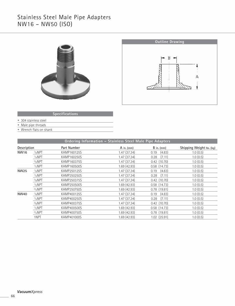
Stainless Steel Male Pipe Adapters NW16 – NW50 (ISO)
66
Description Part Number A in. (mm) B in. (mm) Shipping Weight lbs. (kg)
NW16 1⁄8NPT KAMP160125S 1.47 (37.34) 0.19 (4.83) 1.0 (0.5)1⁄4NPT KAMP160250S 1.47 (37.34) 0.28 (7.11) 1.0 (0.5)3⁄8NPT KAMP160375S 1.47 (37.34) 0.42 (10.70) 1.0 (0.5)1⁄2NPT KAMP160500S 1.69 (42.93) 0.58 (14.73) 1.0 (0.5)
NW25 1⁄8NPT KAMP250125S 1.47 (37.34) 0.19 (4.83) 1.0 (0.5)1⁄4NPT KAMP250250S 1.47 (37.34) 0.28 (7.11) 1.0 (0.5)3⁄8NPT KAMP250375S 1.47 (37.34) 0.42 (10.70) 1.0 (0.5)1⁄2NPT KAMP250500S 1.69 (42.93) 0.58 (14.73) 1.0 (0.5)3⁄4NPT KAMP250750S 1.69 (42.93) 0.78 (19.81) 1.0 (0.5)
NW40 1⁄8NPT KAMP400125S 1.47 (37.34) 0.19 (4.83) 1.0 (0.5)1⁄4NPT KAMP400250S 1.47 (37.34) 0.28 (7.11) 1.0 (0.5)3⁄8NPT KAMP400375S 1.47 (37.34) 0.42 (10.70) 1.0 (0.5)1⁄2NPT KAMP400500S 1.69 (42.93) 0.58 (14.73) 1.0 (0.5)3⁄4NPT KAMP400750S 1.69 (42.93) 0.78 (19.81) 1.0 (0.5)1NPT KAMP401000S 1.69 (42.93) 1.02 (25.91) 1.0 (0.5)
Ordering Information – Stainless Steel Male Pipe Adapters
Outline Drawing
• 304 stainless steel• Male pipe threads• Wrench flats on shank
Specifications
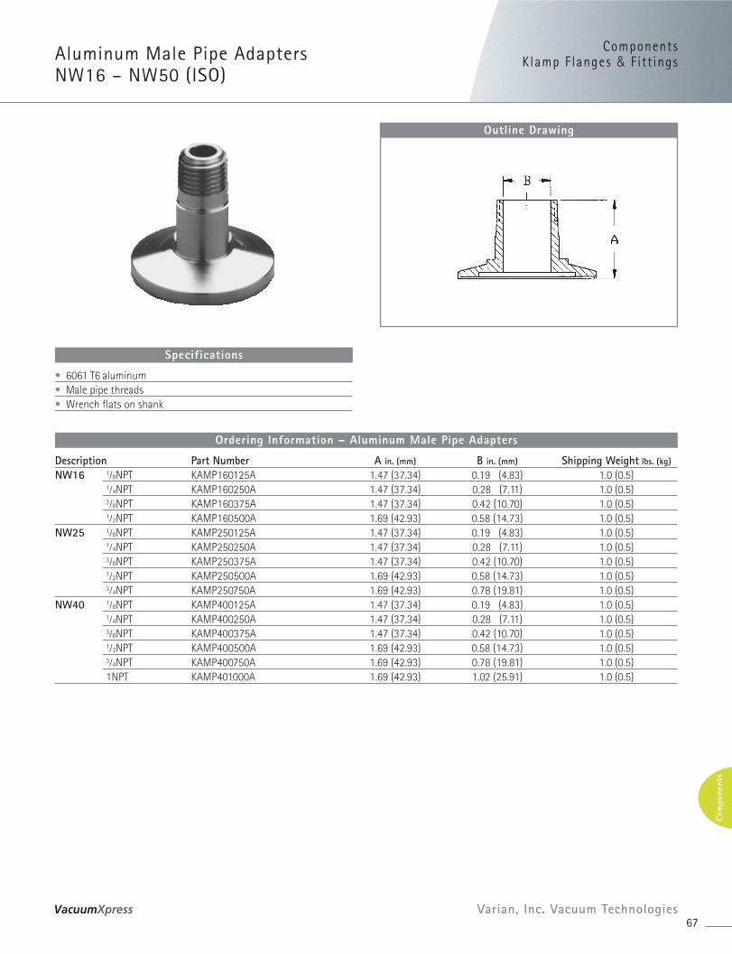
ComponentsKlamp F langes & Fitt ingsAluminum Male Pipe Adapters
NW16 – NW50 (ISO)
67Varian, Inc. Vacuum Technologies
Com
pone
nts
Description Part Number A in. (mm) B in. (mm) Shipping Weight lbs. (kg)
NW16 1⁄8NPT KAMP160125A 1.47 (37.34) 0.19 (4.83) 1.0 (0.5)1⁄4NPT KAMP160250A 1.47 (37.34) 0.28 (7.11) 1.0 (0.5)3⁄8NPT KAMP160375A 1.47 (37.34) 0.42 (10.70) 1.0 (0.5)1⁄2NPT KAMP160500A 1.69 (42.93) 0.58 (14.73) 1.0 (0.5)
NW25 1⁄8NPT KAMP250125A 1.47 (37.34) 0.19 (4.83) 1.0 (0.5)1⁄4NPT KAMP250250A 1.47 (37.34) 0.28 (7.11) 1.0 (0.5)3⁄8NPT KAMP250375A 1.47 (37.34) 0.42 (10.70) 1.0 (0.5)1⁄2NPT KAMP250500A 1.69 (42.93) 0.58 (14.73) 1.0 (0.5)3⁄4NPT KAMP250750A 1.69 (42.93) 0.78 (19.81) 1.0 (0.5)
NW40 1⁄8NPT KAMP400125A 1.47 (37.34) 0.19 (4.83) 1.0 (0.5)1⁄4NPT KAMP400250A 1.47 (37.34) 0.28 (7.11) 1.0 (0.5)3⁄8NPT KAMP400375A 1.47 (37.34) 0.42 (10.70) 1.0 (0.5)1⁄2NPT KAMP400500A 1.69 (42.93) 0.58 (14.73) 1.0 (0.5)3⁄4NPT KAMP400750A 1.69 (42.93) 0.78 (19.81) 1.0 (0.5)1NPT KAMP401000A 1.69 (42.93) 1.02 (25.91) 1.0 (0.5)
Ordering Information – Aluminum Male Pipe Adapters
Outline Drawing
• 6061 T6 aluminum• Male pipe threads• Wrench flats on shank
Specifications
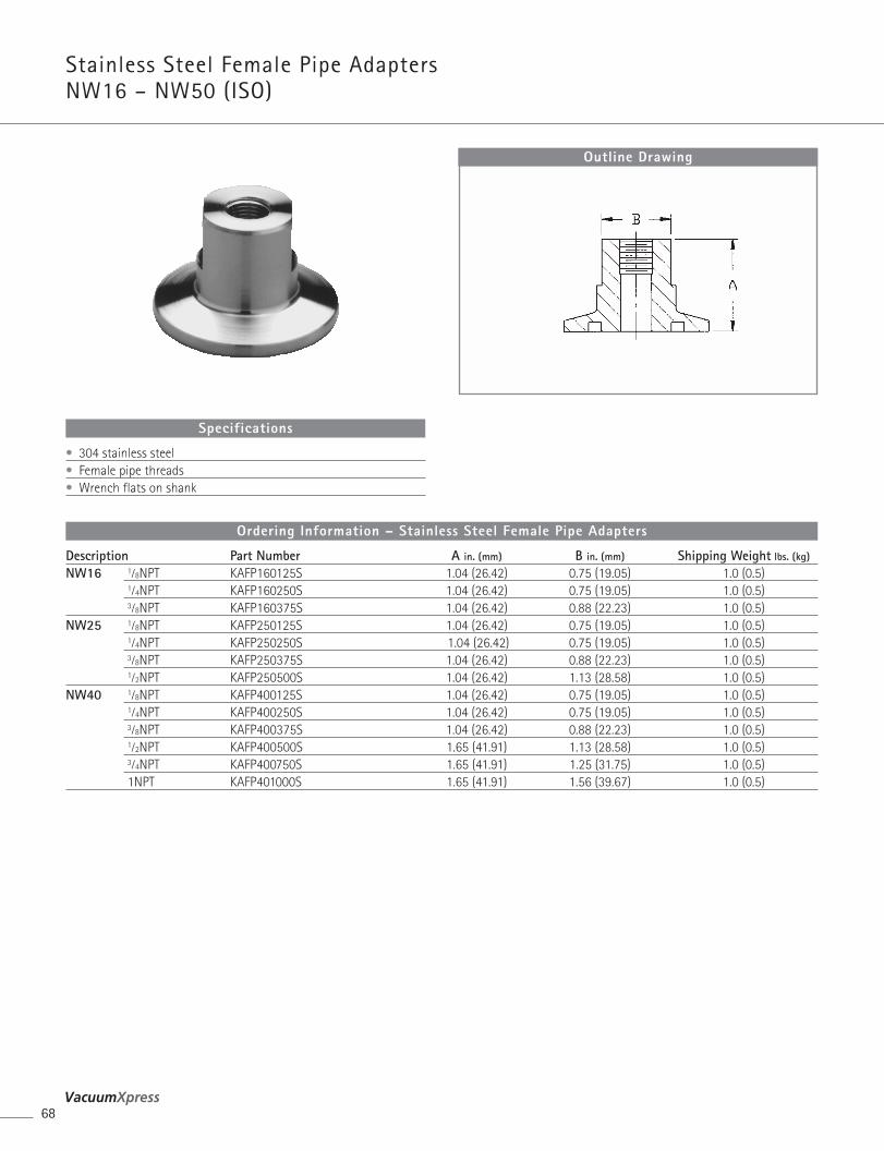
Stainless Steel Female Pipe Adapters NW16 – NW50 (ISO)
68
Description Part Number A in. (mm) B in. (mm) Shipping Weight lbs. (kg)
NW16 1⁄8NPT KAFP160125S 1.04 (26.42) 0.75 (19.05) 1.0 (0.5)1⁄4NPT KAFP160250S 1.04 (26.42) 0.75 (19.05) 1.0 (0.5)3⁄8NPT KAFP160375S 1.04 (26.42) 0.88 (22.23) 1.0 (0.5)
NW25 1⁄8NPT KAFP250125S 1.04 (26.42) 0.75 (19.05) 1.0 (0.5)1⁄4NPT KAFP250250S 1.04 (26.42) 0.75 (19.05) 1.0 (0.5)3⁄8NPT KAFP250375S 1.04 (26.42) 0.88 (22.23) 1.0 (0.5)1⁄2NPT KAFP250500S 1.04 (26.42) 1.13 (28.58) 1.0 (0.5)
NW40 1⁄8NPT KAFP400125S 1.04 (26.42) 0.75 (19.05) 1.0 (0.5)1⁄4NPT KAFP400250S 1.04 (26.42) 0.75 (19.05) 1.0 (0.5)3⁄8NPT KAFP400375S 1.04 (26.42) 0.88 (22.23) 1.0 (0.5)1⁄2NPT KAFP400500S 1.65 (41.91) 1.13 (28.58) 1.0 (0.5)3⁄4NPT KAFP400750S 1.65 (41.91) 1.25 (31.75) 1.0 (0.5)1NPT KAFP401000S 1.65 (41.91) 1.56 (39.67) 1.0 (0.5)
Ordering Information – Stainless Steel Female Pipe Adapters
Outline Drawing
• 304 stainless steel• Female pipe threads• Wrench flats on shank
Specifications

ComponentsKlamp F langes & Fitt ingsAluminum Female Pipe Adapters
NW16 – NW50 (ISO)
69Varian, Inc. Vacuum Technologies
Com
pone
nts
Description Part Number A in. (mm) B in. (mm) Shipping Weight lbs. (kg)
NW16 1⁄8NPT KAFP160125A 1.04 (26.42) 0.75 (19.05) 1.0 (0.5)1⁄4NPT KAFP160250A 1.04 (26.42) 0.75 (19.05) 1.0 (0.5)3⁄8NPT KAFP160375A 1.04 (26.42) 0.88 (22.23) 1.0 (0.5)
NW25 1⁄8NPT KAFP250125A 1.04 (26.42) 0.75 (19.05) 1.0 (0.5)1⁄4NPT KAFP250250A 1.04 (26.42) 0.75 (19.05) 1.0 (0.5)3⁄8NPT KAFP250375A 1.04 (26.42) 0.88 (22.23) 1.0 (0.5)1⁄2NPT KAFP250500A 1.04 (26.42) 1.13 (28.58) 1.0 (0.5)
NW40 1⁄8NPT KAFP400125A 1.04 (26.42) 0.75 (19.05) 1.0 (0.5)1⁄4NPT KAFP400250A 1.04 (26.42) 0.75 (19.05) 1.0 (0.5)3⁄8NPT KAFP400375A 1.04 (26.42) 0.88 (22.23) 1.0 (0.5)1⁄2NPT KAFP400500A 1.65 (41.91) 1.13 (28.58) 1.0 (0.5)3⁄4NPT KAFP400750A 1.65 (41.91) 1.25 (31.75) 1.0 (0.5)1NPT KAFP401000A 1.65 (41.91) 1.56 (39.67) 1.0 (0.5)
Ordering Information – Aluminum Female Pipe Adapters
Outline Drawing
• 6061 T6 aluminum• Female pipe threads• Wrench flats on shank
Specifications
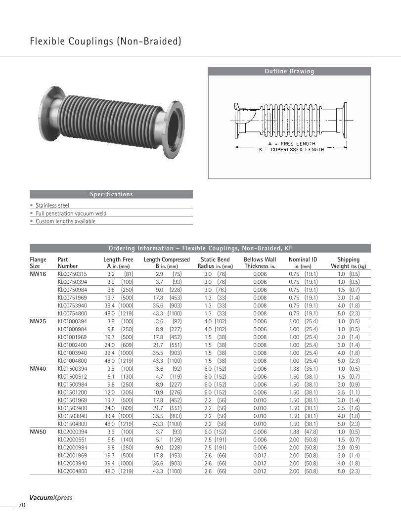
Flexible Couplings (Non-Braided)
70
Flange Part Length Free Length Compressed Static Bend Bellows Wall Nominal ID ShippingSize Number A in. (mm) B in. (mm) Radius in. (mm) Thickness in. in. (mm) Weight lbs (kg)
NW16 KL00750315 3.2 (81) 2.9 (75) 3.0 (76) 0.006 0.75 (19.1) 1.0 (0.5)KL00750394 3.9 (100) 3.7 (93) 3.0 (76) 0.006 0.75 (19.1) 1.0 (0.5)KL00750984 9.8 (250) 9.0 (228) 3.0 (76.) 0.006 0.75 (19.1) 1.5 (0.7)KL00751969 19.7 (500) 17.8 (453) 1.3 (33) 0.008 0.75 (19.1) 3.0 (1.4)KL00753940 39.4 (1000) 35.6 (903) 1.3 (33) 0.008 0.75 (19.1) 4.0 (1.8)KL00754800 48.0 (1219) 43.3 (1100) 1.3 (33) 0.008 0.75 (19.1) 5.0 (2.3)
NW25 KL01000394 3.9 (100) 3.6 (92) 4.0 (102) 0.006 1.00 (25.4) 1.0 (0.5)KL01000984 9.8 (250) 8.9 (227) 4.0 (102) 0.006 1.00 (25.4) 1.0 (0.5)KL01001969 19.7 (500) 17.8 (452) 1.5 (38) 0.008 1.00 (25.4) 3.0 (1.4)KL01002400 24.0 (609) 21.7 (551) 1.5 (38) 0.008 1.00 (25.4) 3.0 (1.4)KL01003940 39.4 (1000) 35.5 (903) 1.5 (38) 0.008 1.00 (25.4) 4.0 (1.8)KL01004800 48.0 (1219) 43.3 (1100) 1.5 (38) 0.008 1.00 (25.4) 5.0 (2.3)
NW40 KL01500394 3.9 (100) 3.6 (92) 6.0 (152) 0.006 1.38 (35.1) 1.0 (0.5)KL01500512 5.1 (130) 4.7 (119) 6.0 (152) 0.006 1.50 (38.1) 1.5 (0.7)KL01500984 9.8 (250) 8.9 (227) 6.0 (152) 0.006 1.50 (38.1) 2.0 (0.9)KL01501200 12.0 (305) 10.9 (276) 6.0 (152) 0.006 1.50 (38.1) 2.5 (1.1)KL01501969 19.7 (500) 17.8 (452) 2.2 (56) 0.010 1.50 (38.1) 3.0 (1.4)KL01502400 24.0 (609) 21.7 (551) 2.2 (56) 0.010 1.50 (38.1) 3.5 (1.6)KL01503940 39.4 (1000) 35.5 (903) 2.2 (56) 0.010 1.50 (38.1) 4.0 (1.8)KL01504800 48.0 (1219) 43.3 (1100) 2.2 (56) 0.010 1.50 (38.1) 5.0 (2.3)
NW50 KL02000394 3.9 (100) 3.7 (93) 6.0 (152) 0.006 1.88 (47.8) 1.0 (0.5)KL02000551 5.5 (140) 5.1 (129) 7.5 (191) 0.006 2.00 (50.8) 1.5 (0.7)KL02000984 9.8 (250) 9.0 (228) 7.5 (191) 0.006 2.00 (50.8) 2.0 (0.9)KL02001969 19.7 (500) 17.8 (453) 2.6 (66) 0.012 2.00 (50.8) 3.0 (1.4)KL02003940 39.4 (1000) 35.6 (903) 2.6 (66) 0.012 2.00 (50.8) 4.0 (1.8)KL02004800 48.0 (1219) 43.3 (1100) 2.6 (66) 0.012 2.00 (50.8) 5.0 (2.3)
Ordering Information – Flexible Couplings, Non-Braided, KF
Outline Drawing
• Stainless steel• Full penetration vacuum weld • Custom lengths available
Specifications
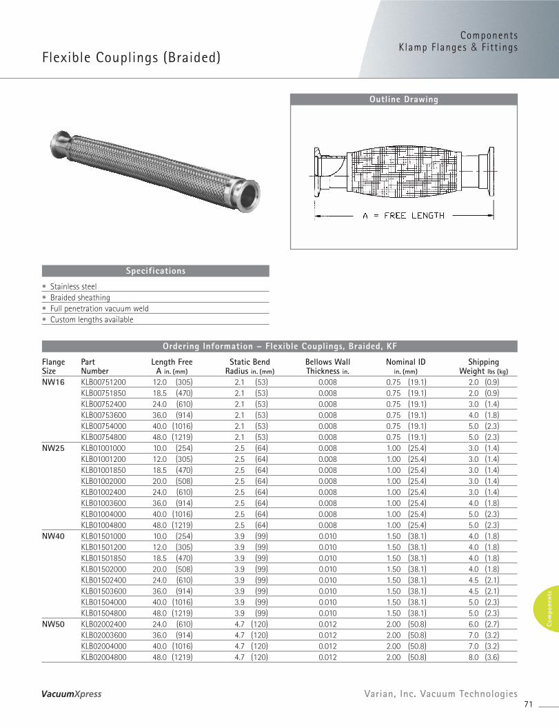
ComponentsKlamp F langes & Fitt ings
Flexible Couplings (Braided)
71Varian, Inc. Vacuum Technologies
Com
pone
nts
Flange Part Length Free Static Bend Bellows Wall Nominal ID ShippingSize Number A in. (mm) Radius in. (mm) Thickness in. in. (mm) Weight lbs (kg)
NW16 KLB00751200 12.0 (305) 2.1 (53) 0.008 0.75 (19.1) 2.0 (0.9)KLB00751850 18.5 (470) 2.1 (53) 0.008 0.75 (19.1) 2.0 (0.9)KLB00752400 24.0 (610) 2.1 (53) 0.008 0.75 (19.1) 3.0 (1.4)KLB00753600 36.0 (914) 2.1 (53) 0.008 0.75 (19.1) 4.0 (1.8)KLB00754000 40.0 (1016) 2.1 (53) 0.008 0.75 (19.1) 5.0 (2.3)KLB00754800 48.0 (1219) 2.1 (53) 0.008 0.75 (19.1) 5.0 (2.3)
NW25 KLB01001000 10.0 (254) 2.5 (64) 0.008 1.00 (25.4) 3.0 (1.4)KLB01001200 12.0 (305) 2.5 (64) 0.008 1.00 (25.4) 3.0 (1.4)KLB01001850 18.5 (470) 2.5 (64) 0.008 1.00 (25.4) 3.0 (1.4)KLB01002000 20.0 (508) 2.5 (64) 0.008 1.00 (25.4) 3.0 (1.4)KLB01002400 24.0 (610) 2.5 (64) 0.008 1.00 (25.4) 3.0 (1.4)KLB01003600 36.0 (914) 2.5 (64) 0.008 1.00 (25.4) 4.0 (1.8)KLB01004000 40.0 (1016) 2.5 (64) 0.008 1.00 (25.4) 5.0 (2.3)KLB01004800 48.0 (1219) 2.5 (64) 0.008 1.00 (25.4) 5.0 (2.3)
NW40 KLB01501000 10.0 (254) 3.9 (99) 0.010 1.50 (38.1) 4.0 (1.8)KLB01501200 12.0 (305) 3.9 (99) 0.010 1.50 (38.1) 4.0 (1.8)KLB01501850 18.5 (470) 3.9 (99) 0.010 1.50 (38.1) 4.0 (1.8)KLB01502000 20.0 (508) 3.9 (99) 0.010 1.50 (38.1) 4.0 (1.8)KLB01502400 24.0 (610) 3.9 (99) 0.010 1.50 (38.1) 4.5 (2.1)KLB01503600 36.0 (914) 3.9 (99) 0.010 1.50 (38.1) 4.5 (2.1)KLB01504000 40.0 (1016) 3.9 (99) 0.010 1.50 (38.1) 5.0 (2.3)KLB01504800 48.0 (1219) 3.9 (99) 0.010 1.50 (38.1) 5.0 (2.3)
NW50 KLB02002400 24.0 (610) 4.7 (120) 0.012 2.00 (50.8) 6.0 (2.7)KLB02003600 36.0 (914) 4.7 (120) 0.012 2.00 (50.8) 7.0 (3.2)KLB02004000 40.0 (1016) 4.7 (120) 0.012 2.00 (50.8) 7.0 (3.2)KLB02004800 48.0 (1219) 4.7 (120) 0.012 2.00 (50.8) 8.0 (3.6)
Ordering Information – Flexible Couplings, Braided, KF
Outline Drawing
• Stainless steel• Braided sheathing• Full penetration vacuum weld • Custom lengths available
Specifications
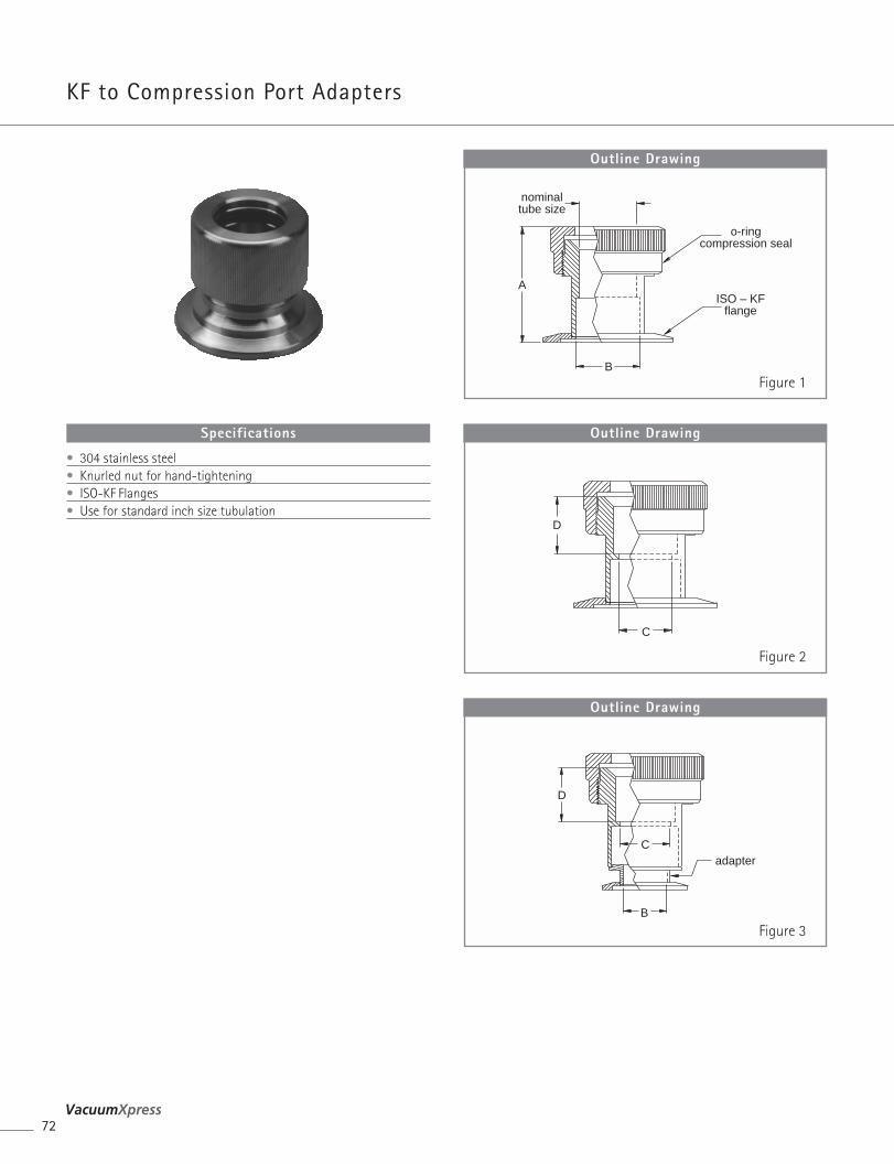
KF to Compression Port Adapters
72
nominaltube size
o-ringcompression seal
ISO – KFflange
B
A
Outline Drawing
C
D
Outline Drawing
adapter
B
C
D
Outline Drawing
• 304 stainless steel• Knurled nut for hand-tightening• ISO-KF Flanges• Use for standard inch size tubulation
Specifications
Figure 1
Figure 2
Figure 3
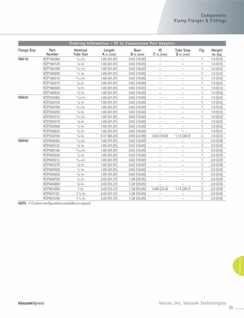
ComponentsKlamp F langes & Fitt ings
73Varian, Inc. Vacuum Technologies
Com
pone
nts
Flange Size Part Nominal Length Bore ID Tube Stop Fig. WeightNumber Tube Size A in. (mm) B in. (mm) C in. (mm) D in. (mm) lbs. (kg)
NW16 KCP160062 1⁄16 in. 1.65 (41.91) 0.63 (16.00) – – 1 1.0 (0.5)KCP160125 1⁄8 in. 1.65 (41.91) 0.63 (16.00) – – 1 1.0 (0.5)KCP160190 3⁄16 in. 1.65 (41.91) 0.63 (16.00) – – 1 1.0 (0.5)KCP160250 1⁄4 in. 1.65 (41.91) 0.63 (16.00) – – 1 1.0 (0.5)KCP160312 5⁄16 in. 1.65 (41.91) 0.63 (16.00) – – 1 1.0 (0.5)KCP160375 3⁄8 in. 1.65 (41.91) 0.63 (16.00) – – 1 1.0 (0.5)KCP160500 1⁄2 in. 1.65 (41.91) 0.63 (16.00) – – 1 1.0 (0.5)KCP160625 5⁄8 in. 1.65 (41.91) 0.63 (16.00) – – 1 1.0 (0.5)
NW25 KCP250062 1⁄16 in. 1.65 (41.91) 0.63 (16.00) – – 1 1.0 (0.5)KCP250125 1⁄8 in. 1.65 (41.91) 0.63 (16.00) – – 1 1.0 (0.5)KCP250190 3⁄16 in. 1.65 (41.91) 0.63 (16.00) – – 1 1.0 (0.5)KCP250250 1⁄4 in. 1.65 (41.91) 0.63 (16.00) – – 1 1.0 (0.5)KCP250312 5⁄16 in. 1.65 (41.91) 0.63 (16.00) – – 1 1.0 (0.5)KCP250375 3⁄8 in. 1.65 (41.91) 0.63 (16.00) – – 1 1.0 (0.5)KCP250500 1⁄2 in. 1.65 (41.91) 0.63 (16.00) – – 1 1.0 (0.5)KCP250625 5⁄8 in. 1.65 (41.91) 0.63 (16.00) – – 1 1.0 (0.5)KCP250750 3⁄4 in. 2.37 (60.20) 0.90 (22.86) 0.63 (16.0) 1.13 (28.7) 3 1.0 (0.5)
NW40 KCP400062 1⁄16 in. 1.65 (41.91) 0.63 (16.00) – – 1 2.0 (0.9)KCP400125 1⁄8 in. 1.65 (41.91) 0.63 (16.00) – – 1 2.0 (0.9)KCP400190 3⁄16 in. 1.65 (41.91) 0.63 (16.00) – – 1 2.0 (0.9)KCP400250 1⁄4 in. 1.65 (41.91) 0.63 (16.00) – – 1 2.0 (0.9)KCP400312 5⁄16 in. 1.65 (41.91) 0.63 (16.00) – – 1 2.0 (0.9)KCP400375 3⁄8 in. 1.65 (41.91) 0.63 (16.00) – – 1 2.0 (0.9)KCP400500 1⁄2 in. 1.65 (41.91) 0.63 (16.00) – – 1 2.0 (0.9)KCP400625 5⁄8 in. 1.65 (41.91) 0.63 (16.00) – – 1 2.0 (0.9)KCP400750 3⁄4 in. 2.02 (51.31) 1.38 (35.05) – – 1 2.0 (0.9)KCP400880 7⁄8 in. 2.02 (51.31) 1.38 (35.05) – – 1 2.0 (0.9)KCP401000 1 in. 2.02 (51.31) 1.38 (35.05) 0.88 (22.4) 1.13 (28.7) 2 2.0 (0.9)KCP401125 11⁄8 in. 2.02 (51.31) 1.38 (35.05) – – 1 2.0 (0.9)KCP401250 11⁄4 in. 2.02 (51.31) 1.38 (35.05) – – 1 2.0 (0.9)
NOTE • Custom configurations available on request
Ordering Information – KF to Compression Port Adapters
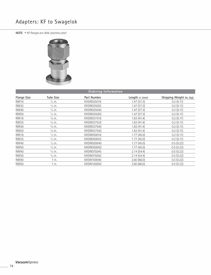
Adapters: KF to Swagelok
74
Flange Size Tube Size Part Number Length in. (mm) Shipping Weight lbs. (kg)
NW16 1⁄4 in. KASW025016 1.47 (37.3) 0.2 (0.11)NW25 1⁄4 in. KASW025025 1.47 (37.3) 0.2 (0.11)NW40 1⁄4 in. KASW025040 1.47 (37.3) 0.2 (0.11)NW50 1⁄4 in. KASW025050 1.47 (37.3) 0.2 (0.11)NW16 3⁄8 in. KASW037516 1.63 (41.4) 0.2 (0.11)NW25 3⁄8 in. KASW037525 1.63 (41.4) 0.2 (0.11)NW40 3⁄8 in. KASW037540 1.63 (41.4) 0.2 (0.11)NW50 3⁄8 in. KASW037550 1.63 (41.4) 0.2 (0.11)NW16 1⁄2 in. KASW050016 1.77 (45.0) 0.2 (0.11)NW25 1⁄2 in. KASW050025 1.77 (45.0) 0.2 (0.11)NW40 1⁄2 in. KASW050040 1.77 (45.0) 0.5 (0.22)NW50 1⁄2 in. KASW050050 1.77 (45.0) 0.5 (0.22)NW40 3⁄4 in. KASW075040 2.14 (54.4) 0.5 (0.22)NW50 3⁄4 in. KASW075050 2.14 (54.4) 0.5 (0.22)NW40 1 in. KASW100040 2.60 (66.0) 0.5 (0.22)NW50 1 in. KASW100050 2.60 (66.0) 0.5 (0.22)
Ordering Information
NOTE • KF flanges are 304L stainless steel
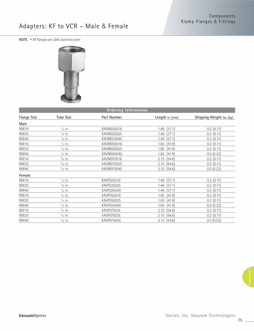
ComponentsKlamp F langes & Fitt ings
Adapters: KF to VCR – Male & Female
75Varian, Inc. Vacuum Technologies
Com
pone
nts
Flange Size Tube Size Part Number Length in. (mm) Shipping Weight lbs. (kg)
MaleNW16 1⁄4 in. KAVM025016 1.46 (37.1) 0.2 (0.11)NW25 1⁄4 in. KAVM025025 1.46 (37.1) 0.2 (0.11)NW40 1⁄4 in. KAVM025040 1.46 (37.1) 0.2 (0.11)NW16 1⁄2 in. KAVM050016 1.65 (41.9) 0.2 (0.11)NW25 1⁄2 in. KAVM050025 1.65 (41.9) 0.2 (0.11)NW40 1⁄2 in. KAVM050040 1.65 (41.9) 0.5 (0.22)NW16 3⁄4 in. KAVM075016 2.15 (54.6) 0.2 (0.11)NW25 3⁄4 in. KAVM075025 2.15 (54.6) 0.2 (0.11)NW40 3⁄4 in. KAVM075040 2.15 (54.6) 0.5 (0.22)
FemaleNW16 1⁄4 in. KAVF025016 1.46 (37.1) 0.2 (0.11)NW25 1⁄4 in. KAVF025025 1.46 (37.1) 0.2 (0.11)NW40 1⁄4 in. KAVF025040 1.46 (37.1) 0.2 (0.11)NW16 1⁄2 in. KAVF050016 1.65 (41.9) 0.2 (0.11)NW25 1⁄2 in. KAVF050025 1.65 (41.9) 0.2 (0.11)NW40 1⁄2 in. KAVF050040 1.65 (41.9) 0.5 (0.22)NW16 3⁄4 in. KAVF075016 2.15 (54.6) 0.2 (0.11)NW25 3⁄4 in. KAVF075025 2.15 (54.6) 0.2 (0.11)NW40 3⁄4 in. KAVF075040 2.15 (54.6) 0.5 (0.22)
Ordering Information
NOTE • KF flanges are 304L stainless steel
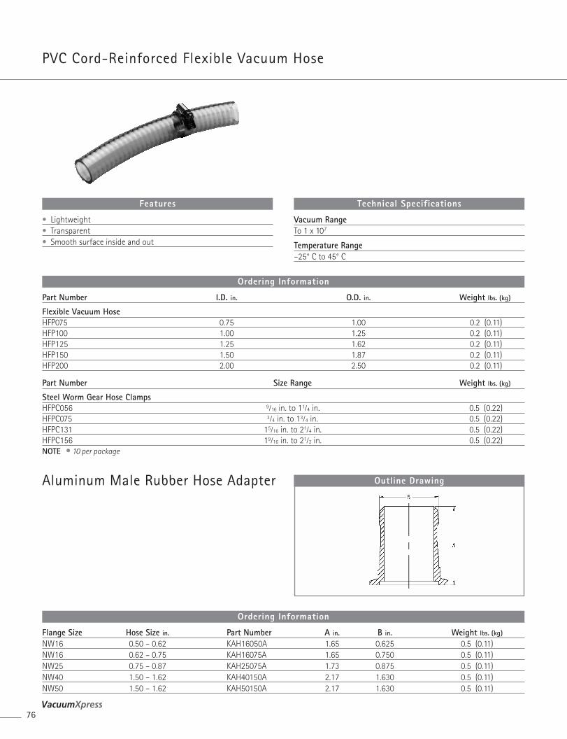
PVC Cord-Reinforced Flexible Vacuum Hose
Aluminum Male Rubber Hose Adapter
76
Outline Drawing
• Lightweight• Transparent• Smooth surface inside and out
Features
Vacuum RangeTo 1 x 10⁷
Temperature Range–25° C to 45° C
Technical Specifications
Part Number I.D. in. O.D. in. Weight lbs. (kg)
Flexible Vacuum HoseHFP075 0.75 1.00 0.2 (0.11)HFP100 1.00 1.25 0.2 (0.11)HFP125 1.25 1.62 0.2 (0.11)HFP150 1.50 1.87 0.2 (0.11)HFP200 2.00 2.50 0.2 (0.11)
Part Number Size Range Weight lbs. (kg)
Steel Worm Gear Hose ClampsHFPC056 9⁄16 in. to 11⁄4 in. 0.5 (0.22)HFPC075 3⁄4 in. to 13⁄4 in. 0.5 (0.22)HFPC131 15⁄16 in. to 21⁄4 in. 0.5 (0.22)HFPC156 19⁄16 in. to 21⁄2 in. 0.5 (0.22)NOTE • 10 per package
Ordering Information
Flange Size Hose Size in. Part Number A in. B in. Weight lbs. (kg)
NW16 0.50 – 0.62 KAH16050A 1.65 0.625 0.5 (0.11)NW16 0.62 – 0.75 KAH16075A 1.65 0.750 0.5 (0.11)NW25 0.75 – 0.87 KAH25075A 1.73 0.875 0.5 (0.11)NW40 1.50 – 1.62 KAH40150A 2.17 1.630 0.5 (0.11)NW50 1.50 – 1.62 KAH50150A 2.17 1.630 0.5 (0.11)
Ordering Information
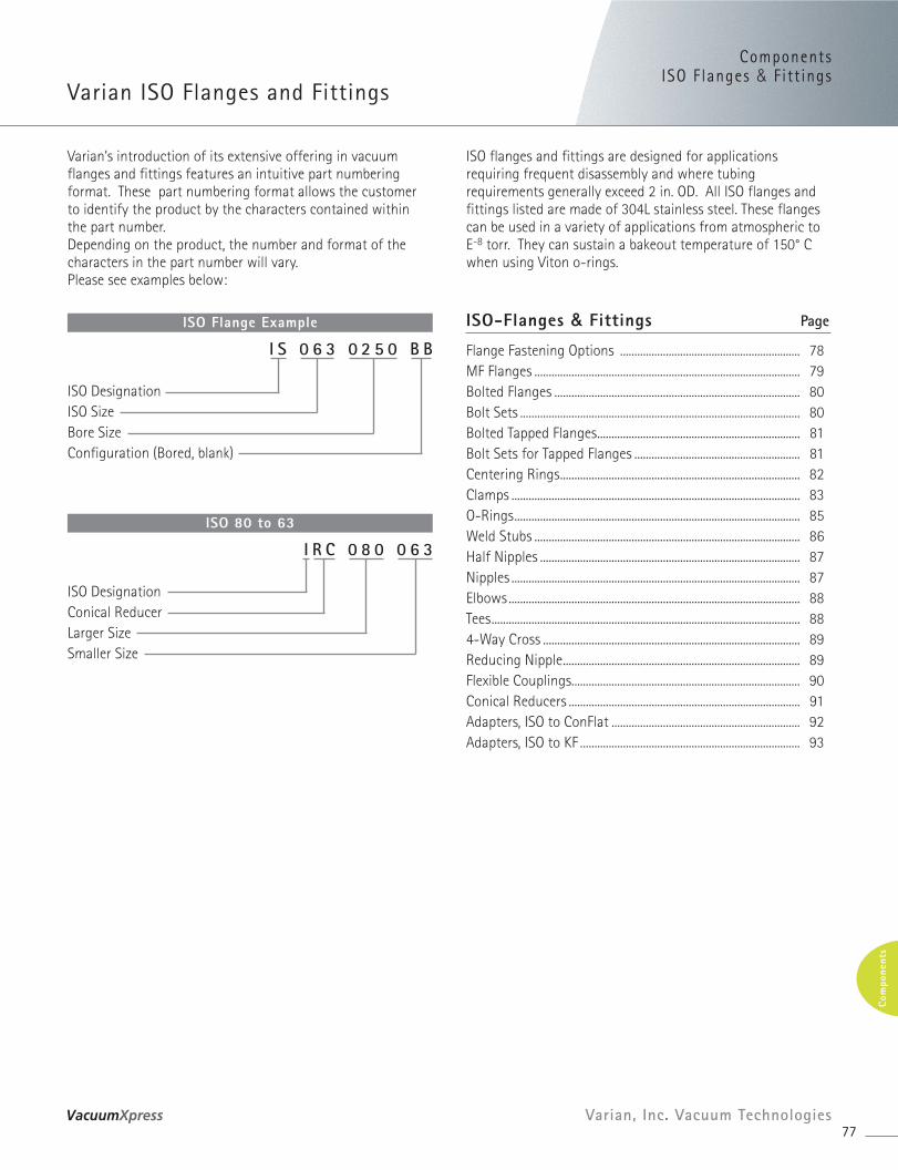
ComponentsISO F langes & Fitt ings
Varian ISO Flanges and Fittings
77Varian, Inc. Vacuum Technologies
Com
pone
nts
ISO flanges and fittings are designed for applicationsrequiring frequent disassembly and where tubingrequirements generally exceed 2 in. OD. All ISO flanges andfittings listed are made of 304L stainless steel. These flangescan be used in a variety of applications from atmospheric toE-8 torr. They can sustain a bakeout temperature of 150° Cwhen using Viton o-rings.
ISO-Flanges & Fittings Page
Flange Fastening Options ............................................................... 78MF Flanges ............................................................................................. 79Bolted Flanges ...................................................................................... 80Bolt Sets .................................................................................................. 80Bolted Tapped Flanges....................................................................... 81Bolt Sets for Tapped Flanges .......................................................... 81Centering Rings.................................................................................... 82Clamps ..................................................................................................... 83O-Rings.................................................................................................... 85Weld Stubs ............................................................................................. 86Half Nipples ........................................................................................... 87Nipples ..................................................................................................... 87Elbows ...................................................................................................... 88Tees............................................................................................................ 884-Way Cross .......................................................................................... 89Reducing Nipple................................................................................... 89Flexible Couplings................................................................................ 90Conical Reducers ................................................................................. 91Adapters, ISO to ConFlat .................................................................. 92Adapters, ISO to KF ............................................................................. 93
ISO Flange Example
I S 0 6 3 0 2 5 0 B B
ISO DesignationISO SizeBore SizeConfiguration (Bored, blank)
Varian’s introduction of its extensive offering in vacuumflanges and fittings features an intuitive part numberingformat. These part numbering format allows the customerto identify the product by the characters contained within the part number.Depending on the product, the number and format of thecharacters in the part number will vary. Please see examples below:
ISO 80 to 63
I R C 0 8 0 0 6 3
ISO DesignationConical ReducerLarger SizeSmaller Size
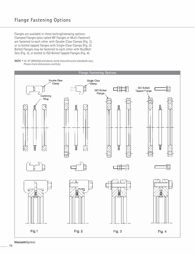
Flange Fastening Options
78
Flange Fastening Options
Flanges are available in these bolting/clamping options:Clamped Flanges (also called MF Flanges or Multi-Fastener)are fastened to each other with Double-Claw Clamps (Fig. 1),or to bolted tapped flanges with Single-Claw Clamps (Fig. 2).Bolted Flanges may be fastened to each other with Nut/BoltSets (Fig. 3), or bolted to ISO Bolted Tapped Flanges (Fig. 4).
NOTE • At 10” (NW250) and above, some manufacturers standards vary.Please check dimensions carefully.
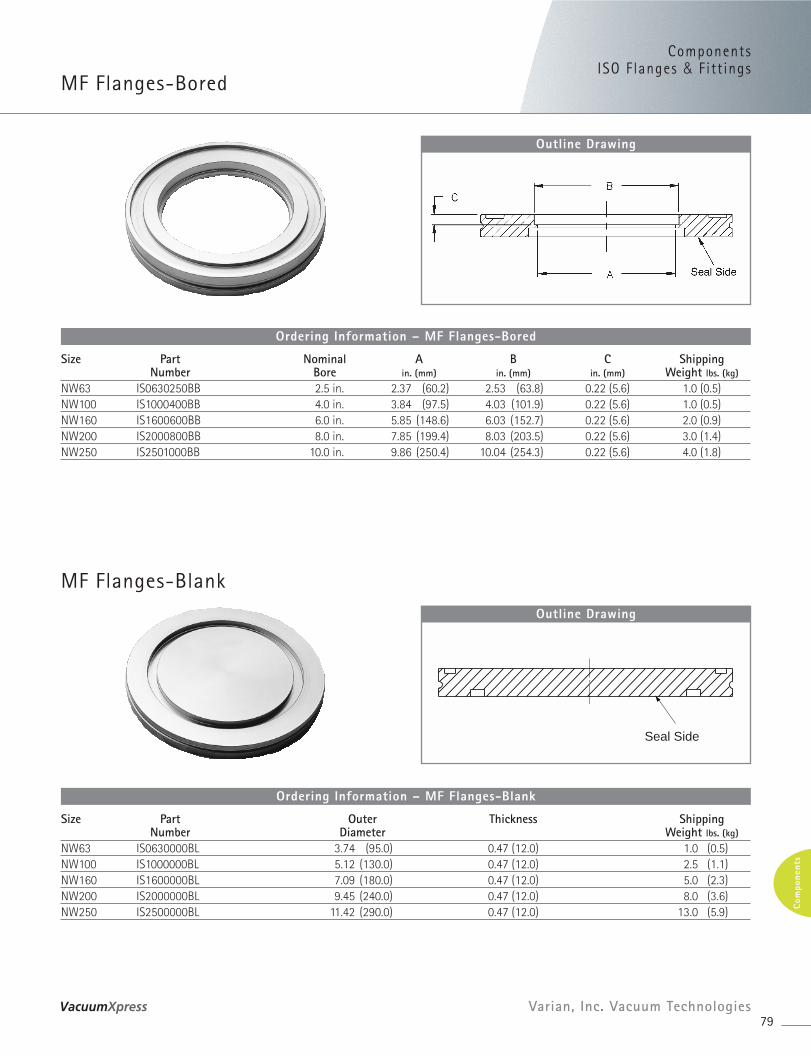
MF Flanges-Blank
ComponentsISO F langes & Fitt ings
MF Flanges-Bored
79Varian, Inc. Vacuum Technologies
Com
pone
nts
Size Part Nominal A B C ShippingNumber Bore in. (mm) in. (mm) in. (mm) Weight lbs. (kg)
NW63 IS0630250BB 2.5 in. 2.37 (60.2) 2.53 (63.8) 0.22 (5.6) 1.0 (0.5)NW100 IS1000400BB 4.0 in. 3.84 (97.5) 4.03 (101.9) 0.22 (5.6) 1.0 (0.5)NW160 IS1600600BB 6.0 in. 5.85 (148.6) 6.03 (152.7) 0.22 (5.6) 2.0 (0.9)NW200 IS2000800BB 8.0 in. 7.85 (199.4) 8.03 (203.5) 0.22 (5.6) 3.0 (1.4)NW250 IS2501000BB 10.0 in. 9.86 (250.4) 10.04 (254.3) 0.22 (5.6) 4.0 (1.8)
Ordering Information – MF Flanges-Bored
Outline Drawing
Size Part Outer Thickness ShippingNumber Diameter Weight lbs. (kg)
NW63 IS0630000BL 3.74 (95.0) 0.47 (12.0) 1.0 (0.5)NW100 IS1000000BL 5.12 (130.0) 0.47 (12.0) 2.5 (1.1)NW160 IS1600000BL 7.09 (180.0) 0.47 (12.0) 5.0 (2.3)NW200 IS2000000BL 9.45 (240.0) 0.47 (12.0) 8.0 (3.6)NW250 IS2500000BL 11.42 (290.0) 0.47 (12.0) 13.0 (5.9)
Ordering Information – MF Flanges-Blank
Seal Side
Outline Drawing
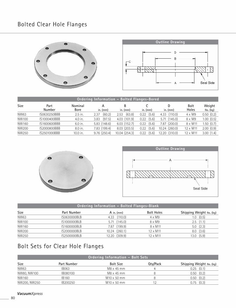
Bolted Clear Hole Flanges
Bolt Sets for Clear Hole Flanges
80
Size Part Nominal A B C D Bolt WeightNumber Bore in. (mm) in. (mm) in. (mm) in. (mm) Holes lbs. (kg)
NW63 IS0630250BBB 2.5 in. 2.37 (60.2) 2.53 (63.8) 0.22 (5.6) 4.33 (110.0) 4 x M9 0.50 (0.2)NW100 IS1000400BBB 4.0 in. 3.83 (97.5) 4.03 (101.9) 0.22 (5.6) 5.71 (145.0) 8 x M9 1.00 (0.5)NW160 IS1600600BBB 6.0 in. 5.83 (148.6) 6.03 (152.7) 0.22 (5.6) 7.87 (200.0) 8 x M11 1.50 (0.7)NW200 IS2000800BBB 8.0 in. 7.83 (199.4) 8.03 (203.5) 0.22 (5.6) 10.24 (260.0) 12 x M11 2.00 (0.9)NW250 IS2501000BBB 10.0 in. 9.76 (250.4) 10.04 (254.3) 0.22 (5.6) 12.20 (310.0) 12 x M11 3.00 (1.4)
Ordering Information – Bolted Flanges-Bored
Outline Drawing
Size Part Number A in. (mm) Bolt Holes Shipping Weight lbs. (kg)
NW63 IS0630000BLB 4.33 (110.0) 4 x M9 1.0 (0.5)NW100 IS1000000BLB 5.71 (145.0) 8 x M9 2.5 (1.1)NW160 IS1600000BLB 7.87 (199.9) 8 x M11 5.0 (2.3)NW200 IS2000000BLB 10.24 (260.1) 12 x M11 8.0 (3.6)NW250 IS2500000BLB 12.20 (309.9) 12 x M11 13.0 (5.9)
Ordering Information – Bolted Flanges-Blank
Size Part Number Bolt Size Qty/Pack Shipping Weight lbs. (kg)
NW63 IB063 M8 x 45 mm 4 0.25 (0.1)NW80, NW100 IB080100 M8 x 45 mm 8 0.50 (0.2)NW160 IB160 M10 x 50 mm 8 0.50 (0.2)NW200, NW250 IB200250 M10 x 50 mm 12 0.75 (0.3)
Ordering Information – Bolt Sets
A
Seal Side
Outline Drawing
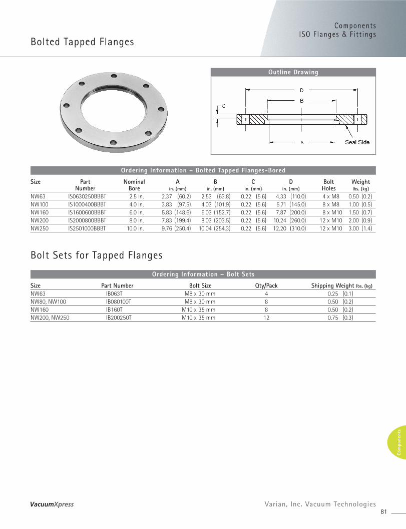
ComponentsISO F langes & Fitt ings
Bolted Tapped Flanges
81Varian, Inc. Vacuum Technologies
Com
pone
nts
Size Part Nominal A B C D Bolt WeightNumber Bore in. (mm) in. (mm) in. (mm) in. (mm) Holes lbs. (kg)
NW63 IS0630250BBBT 2.5 in. 2.37 (60.2) 2.53 (63.8) 0.22 (5.6) 4.33 (110.0) 4 x M8 0.50 (0.2)NW100 IS1000400BBBT 4.0 in. 3.83 (97.5) 4.03 (101.9) 0.22 (5.6) 5.71 (145.0) 8 x M8 1.00 (0.5)NW160 IS1600600BBBT 6.0 in. 5.83 (148.6) 6.03 (152.7) 0.22 (5.6) 7.87 (200.0) 8 x M10 1.50 (0.7)NW200 IS2000800BBBT 8.0 in. 7.83 (199.4) 8.03 (203.5) 0.22 (5.6) 10.24 (260.0) 12 x M10 2.00 (0.9)NW250 IS2501000BBBT 10.0 in. 9.76 (250.4) 10.04 (254.3) 0.22 (5.6) 12.20 (310.0) 12 x M10 3.00 (1.4)
Ordering Information – Bolted Tapped Flanges-Bored
Outline Drawing
Bolt Sets for Tapped Flanges
Size Part Number Bolt Size Qty/Pack Shipping Weight lbs. (kg)
NW63 IB063T M8 x 30 mm 4 0.25 (0.1)NW80, NW100 IB080100T M8 x 30 mm 8 0.50 (0.2)NW160 IB160T M10 x 35 mm 8 0.50 (0.2)NW200, NW250 IB200250T M10 x 35 mm 12 0.75 (0.3)
Ordering Information – Bolt Sets
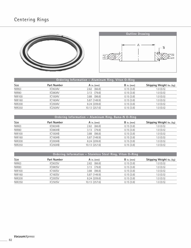
Centering Rings
82
Size Part Number A in. (mm) B in. (mm) Shipping Weight lbs. (kg)
NW63 IC063AV 2.62 (66.8) 0.15 (3.8) 1.0 (0.5)NW80 IC080AV 3.13 (79.8) 0.15 (3.8) 1.0 (0.5)NW100 IC100AV 3.88 (98.8) 0.15 (3.8) 1.0 (0.5)NW160 IC160AV 5.87 (149.9) 0.15 (3.8) 1.0 (0.5)NW200 IC200AV 8.24 (209.8) 0.15 (3.8) 1.0 (0.5)NW250 IC250AV 10.13 (257.6) 0.15 (3.8) 1.0 (0.5)
Ordering Information – Aluminum Ring, Viton O-Ring
Size Part Number A in. (mm) B in. (mm) Shipping Weight lbs. (kg)
NW63 IC063AB 2.62 (66.8) 0.15 (3.8) 1.0 (0.5)NW80 IC080AB 3.13 (79.8) 0.15 (3.8) 1.0 (0.5)NW100 IC100AB 3.88 (98.8) 0.15 (3.8) 1.0 (0.5)NW160 IC160AB 5.87 (149.9) 0.15 (3.8) 1.0 (0.5)NW200 IC200AB 8.24 (209.8) 0.15 (3.8) 1.0 (0.5)NW250 IC250AB 10.13 (257.6) 0.15 (3.8) 1.0 (0.5)
Ordering Information – Aluminum Ring, Buna-N O-Ring
Size Part Number A in. (mm) B in. (mm) Shipping Weight lbs. (kg)
NW63 IC063SV 2.62 (66.8) 0.15 (3.8) 1.0 (0.5)NW80 IC080SV 3.13 (79.8) 0.15 (3.8) 1.0 (0.5)NW100 IC100SV 3.88 (98.8) 0.15 (3.8) 1.0 (0.5)NW160 IC160SV 5.87 (149.9) 0.15 (3.8) 1.0 (0.5)NW200 IC200SV 8.24 (209.8) 0.15 (3.8) 1.0 (0.5)NW250 IC250SV 10.13 (257.6) 0.15 (3.8) 1.0 (0.5)
Ordering Information – Stainless Steel Ring, Viton O-Ring
Outline Drawing
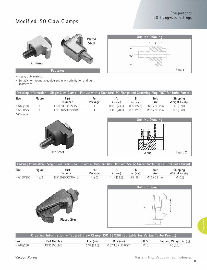
PlatedSteel
Aluminum
ComponentsISO F langes & Fitt ings
Modified ISO Claw Clamps
83Varian, Inc. Vacuum Technologies
Com
pone
nts
Size Figure Part Per A B Bolt ShippingNumber Package in. (mm) in. (mm) Size Weight lbs. (kg)
NW63/100 1 ICS063100CC22X5S 4 0.925 (23.5) 0.87 (22.5) M8 x 35 mm 1.0 (0.50)NW160/250 1 ICS160250CC23X0A* 1 1.126 (28.6) 0.91 (23.1) M10 x 35 mm 0.5 (0.20)* Aluminum
Ordering Information – Single Claw Clamp – For use with a Standard ISO Flange and Centering Ring (NOT for Turbo Pumps)
• Heavy duty material• Suitable for mounting equipment in any orientation and tight
geometrics
Features
“B”
“A”
Outline Drawing
Figure 1
Cast Steel
Size Figure Part Per A B Bolt ShippingNumber Package in. (mm) in. (mm) Size Weight lbs. (kg)
NW160/250 1 & 2 ICS160250CC19X1S 1 & 2 1.14 (28.8) .75 (19.1) M10 x 35 mm 1.0 (0.5)
Ordering Information – Single Claw Clamp – For use with a Flange and Base Plate with Sealing Groove and O-ring (NOT for Turbo Pumps)
Outline Drawing
Figure 2
Plated Steel
Size Part Number A in. (mm) B in. (mm) Bolt Size Shipping Weight lbs. (kg)
NW63/250 IC63250DCMZ 2.34 (59.5) 0.67/1.05 (17.0/27) M10 1.0 (0.5)
Ordering Information – Tapered Claw Clamp, ISO 63/250 (Suitable for Varian Turbo Pumps)
“A”“B”
Outline Drawing
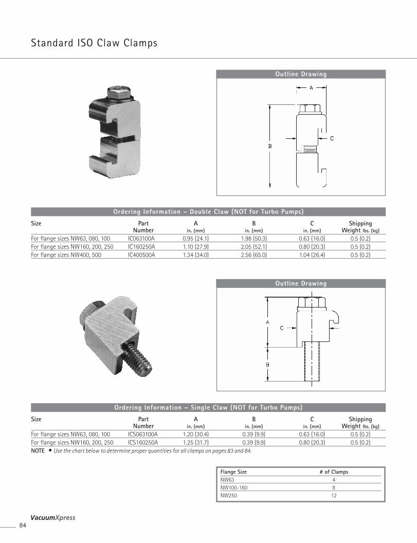
Standard ISO Claw Clamps
84
Size Part A B C ShippingNumber in. (mm) in. (mm) in. (mm) Weight lbs. (kg)
For flange sizes NW63, 080, 100 IC063100A 0.95 (24.1) 1.98 (50.3) 0.63 (16.0) 0.5 (0.2)For flange sizes NW160, 200, 250 IC160250A 1.10 (27.9) 2.05 (52.1) 0.80 (20.3) 0.5 (0.2)For flange sizes NW400, 500 IC400500A 1.34 (34.0) 2.56 (65.0) 1.04 (26.4) 0.5 (0.2)
Ordering Information – Double Claw (NOT for Turbo Pumps)
Outline Drawing
Size Part A B C ShippingNumber in. (mm) in. (mm) in. (mm) Weight lbs. (kg)
For flange sizes NW63, 080, 100 ICS063100A 1.20 (30.4) 0.39 (9.9) 0.63 (16.0) 0.5 (0.2)For flange sizes NW160, 200, 250 ICS160250A 1.25 (31.7) 0.39 (9.9) 0.80 (20.3) 0.5 (0.2)NOTE • Use the chart below to determine proper quantities for all clamps on pages 83 and 84.
Ordering Information – Single Claw (NOT for Turbo Pumps)
Outline Drawing
Flange Size # of ClampsNW63 4NW100-160 8NW250 12
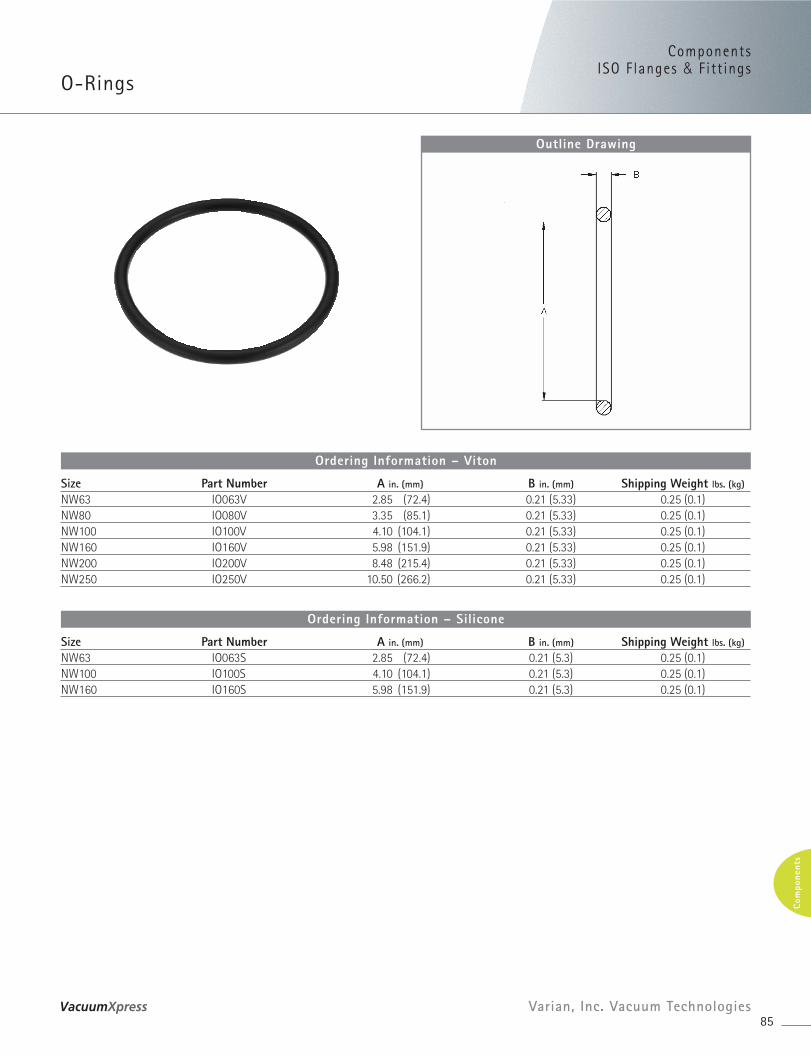
ComponentsISO F langes & Fitt ings
O-Rings
85Varian, Inc. Vacuum Technologies
Com
pone
nts
Outline Drawing
Size Part Number A in. (mm) B in. (mm) Shipping Weight lbs. (kg)
NW63 IO063V 2.85 (72.4) 0.21 (5.33) 0.25 (0.1)NW80 IO080V 3.35 (85.1) 0.21 (5.33) 0.25 (0.1)NW100 IO100V 4.10 (104.1) 0.21 (5.33) 0.25 (0.1)NW160 IO160V 5.98 (151.9) 0.21 (5.33) 0.25 (0.1)NW200 IO200V 8.48 (215.4) 0.21 (5.33) 0.25 (0.1)NW250 IO250V 10.50 (266.2) 0.21 (5.33) 0.25 (0.1)
Ordering Information – Viton
Size Part Number A in. (mm) B in. (mm) Shipping Weight lbs. (kg)
NW63 IO063S 2.85 (72.4) 0.21 (5.3) 0.25 (0.1)NW100 IO100S 4.10 (104.1) 0.21 (5.3) 0.25 (0.1)NW160 IO160S 5.98 (151.9) 0.21 (5.3) 0.25 (0.1)
Ordering Information – Silicone
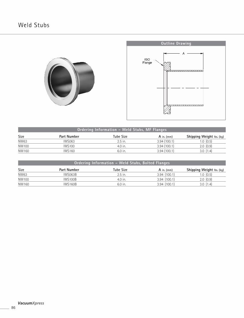
Weld Stubs
86
Outline Drawing
Size Part Number Tube Size A in. (mm) Shipping Weight lbs. (kg)
NW63 IWS063 2.5 in. 3.94 (100.1) 1.0 (0.5)NW100 IWS100 4.0 in. 3.94 (100.1) 2.0 (0.9)NW160 IWS160 6.0 in. 3.94 (100.1) 3.0 (1.4)
Ordering Information – Weld Stubs, MF Flanges
Size Part Number Tube Size A in. (mm) Shipping Weight lbs. (kg)
NW63 IWS063B 2.5 in. 3.94 (100.1) 1.0 (0.5)NW100 IWS100B 4.0 in. 3.94 (100.1) 2.0 (0.9)NW160 IWS160B 6.0 in. 3.94 (100.1) 3.0 (1.4)
Ordering Information – Weld Stubs, Bolted Flanges
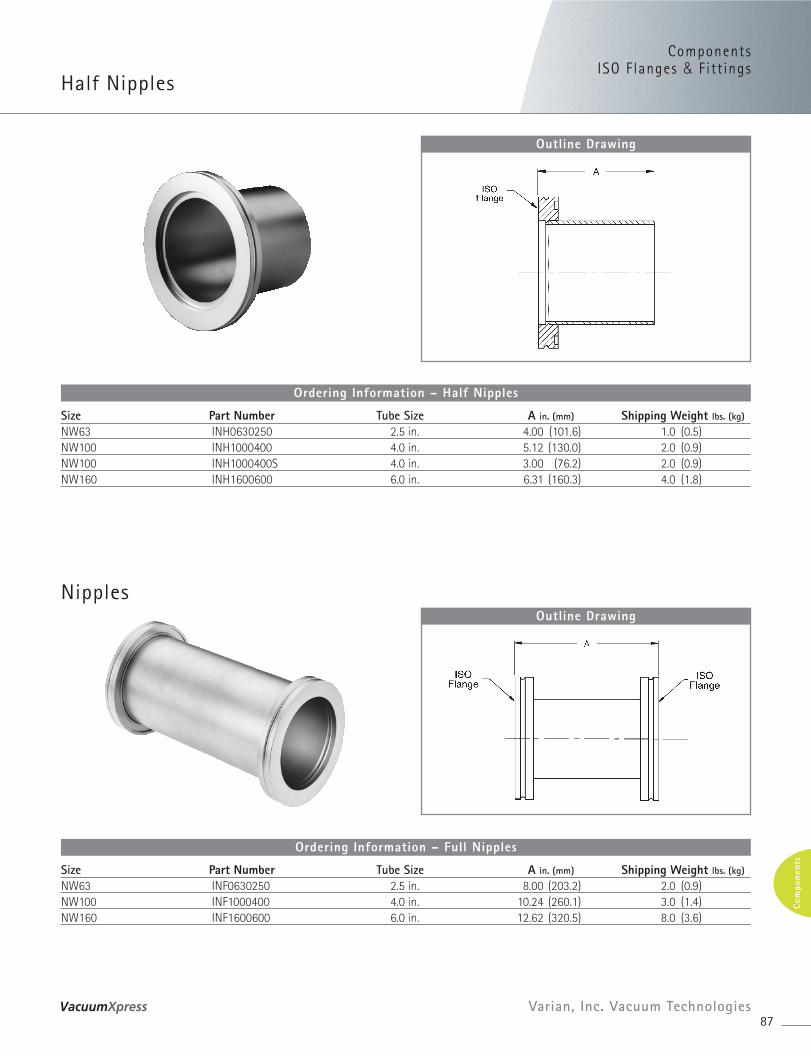
Nipples
ComponentsISO F langes & Fitt ings
Half Nipples
87Varian, Inc. Vacuum Technologies
Com
pone
nts
Outline Drawing
Size Part Number Tube Size A in. (mm) Shipping Weight lbs. (kg)
NW63 INH0630250 2.5 in. 4.00 (101.6) 1.0 (0.5)NW100 INH1000400 4.0 in. 5.12 (130.0) 2.0 (0.9)NW100 INH1000400S 4.0 in. 3.00 (76.2) 2.0 (0.9)NW160 INH1600600 6.0 in. 6.31 (160.3) 4.0 (1.8)
Ordering Information – Half Nipples
Outline Drawing
Size Part Number Tube Size A in. (mm) Shipping Weight lbs. (kg)
NW63 INF0630250 2.5 in. 8.00 (203.2) 2.0 (0.9)NW100 INF1000400 4.0 in. 10.24 (260.1) 3.0 (1.4)NW160 INF1600600 6.0 in. 12.62 (320.5) 8.0 (3.6)
Ordering Information – Full Nipples
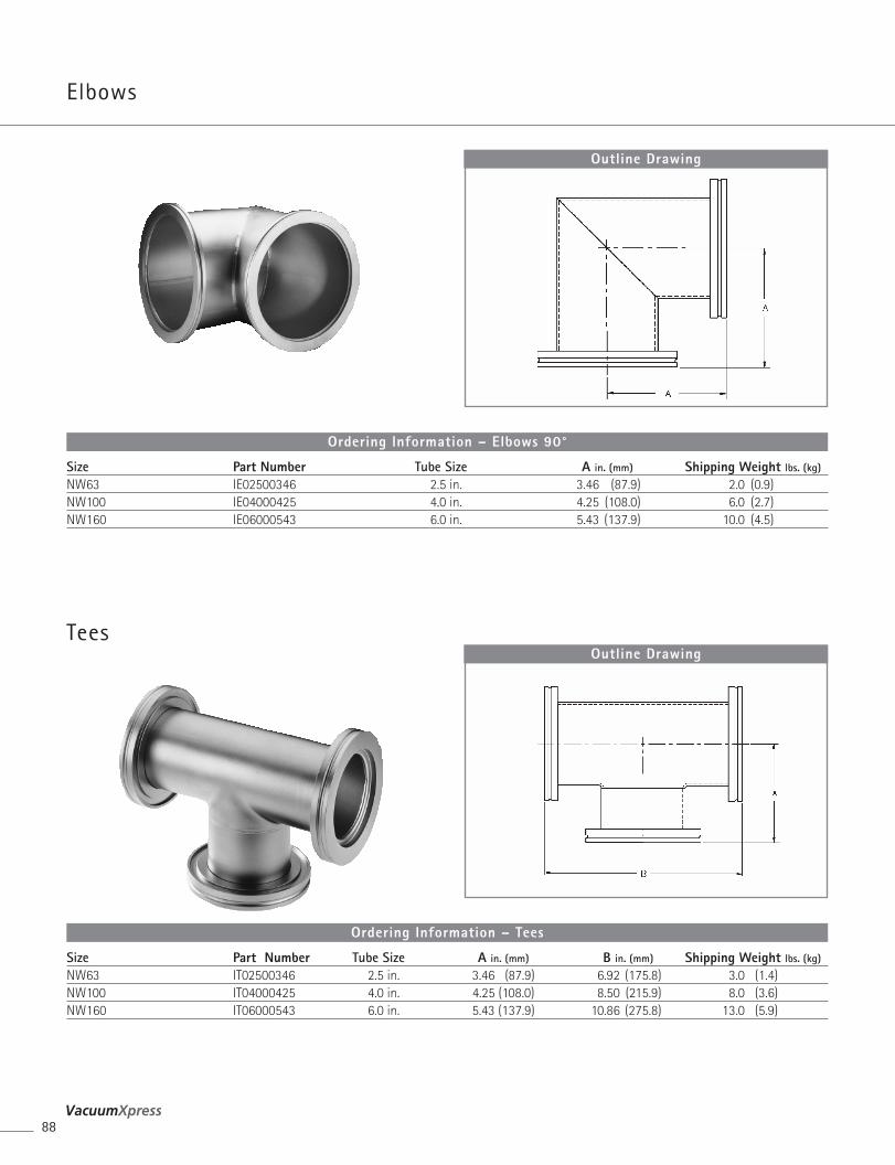
Elbows
Tees
88
Outline Drawing
Size Part Number Tube Size A in. (mm) Shipping Weight lbs. (kg)
NW63 IE02500346 2.5 in. 3.46 (87.9) 2.0 (0.9)NW100 IE04000425 4.0 in. 4.25 (108.0) 6.0 (2.7)NW160 IE06000543 6.0 in. 5.43 (137.9) 10.0 (4.5)
Ordering Information – Elbows 90°
Outline Drawing
Size Part Number Tube Size A in. (mm) B in. (mm) Shipping Weight lbs. (kg)
NW63 IT02500346 2.5 in. 3.46 (87.9) 6.92 (175.8) 3.0 (1.4)NW100 IT04000425 4.0 in. 4.25 (108.0) 8.50 (215.9) 8.0 (3.6)NW160 IT06000543 6.0 in. 5.43 (137.9) 10.86 (275.8) 13.0 (5.9)
Ordering Information – Tees
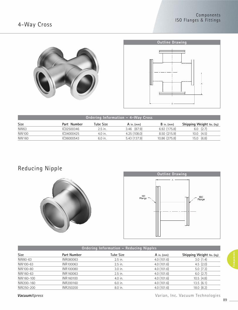
ComponentsISO F langes & Fitt ings
4-Way Cross
89Varian, Inc. Vacuum Technologies
Com
pone
nts
Outline Drawing
Size Part Number Tube Size A in. (mm) B in. (mm) Shipping Weight lbs. (kg)
NW63 IC02500346 2.5 in. 3.46 (87.9) 6.92 (175.8) 6.0 (2.7)NW100 IC04000425 4.0 in. 4.25 (108.0) 8.50 (215.9) 10.0 (4.5)NW160 IC06000543 6.0 in. 5.43 (137.9) 10.86 (275.8) 15.0 (6.8)
Ordering Information – 4-Way Cross
Reducing NippleOutline Drawing
Size Part Number Tube Size A in. (mm) Shipping Weight lbs. (kg)
NW80-63 INR080063 2.5 in. 4.0 (101.6) 3.0 (1.4)NW100-63 INR100063 2.5 in. 4.0 (101.6) 4.5 (2.0)NW100-80 INR100080 3.0 in. 4.0 (101.6) 5.0 (7.3)NW160-63 INR160063 2.5 in. 4.0 (101.6) 6.0 (2.7)NW160-100 INR160100 4.0 in. 4.0 (101.6) 10.5 (4.8)NW200-160 INR200160 6.0 in. 4.0 (101.6) 13.5 (6.1)NW250-200 INR250200 8.0 in. 4.0 (101.6) 18.0 (8.2)
Ordering Information – Reducing Nipples
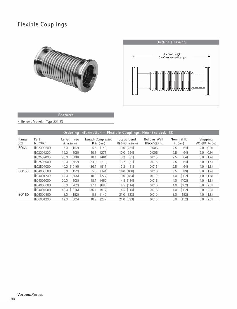
Flexible Couplings
90
Outline Drawing
• Bellows Material: Type 321 SS
Features
Flange Part Length Free Length Compressed Static Bend Bellows Wall Nominal ID ShippingSize Number A in. (mm) B in. (mm) Radius in. (mm) Thickness in. in. (mm) Weight lbs (kg)
ISO63 IL02000600 6.0 (152) 5.5 (140) 10.0 (254) 0.006 2.5 (64) 2.0 (0.9)IL02001200 12.0 (305) 10.9 (277) 10.0 (254) 0.006 2.5 (64) 2.0 (0.9)IL02502000 20.0 (508) 18.1 (461) 3.2 (81) 0.015 2.5 (64) 3.0 (1.4)IL02503000 30.0 (762) 24.0 (610) 3.2 (81) 0.015 2.5 (64) 3.0 (1.4)IL02504000 40.0 (1016) 36.1 (917) 3.2 (81) 0.015 2.5 (64) 4.0 (1.8)
ISO100 IL04000600 6.0 (152) 5.5 (141) 16.0 (406) 0.016 3.5 (89) 3.0 (1.4)IL04001200 12.0 (305) 10.9 (277) 19.0 (483) 0.010 4.0 (102) 4.0 (1.8)IL04002000 20.0 (508) 18.1 (460) 4.5 (114) 0.016 4.0 (102) 4.0 (1.8)IL04003000 30.0 (762) 27.1 (688) 4.5 (114) 0.016 4.0 (102) 5.0 (2.3)IL04004000 40.0 (1016) 36.1 (917) 4.5 (114) 0.016 4.0 (102) 5.0 (2.3)
ISO160 IL06000600 6.0 (152) 5.5 (140) 21.0 (533) 0.010 6.0 (152) 4.0 (1.8)IL06001200 12.0 (305) 10.9 (277) 21.0 (533) 0.010 6.0 (152) 5.0 (2.3)
Ordering Information – Flexible Couplings, Non-Braided, ISO
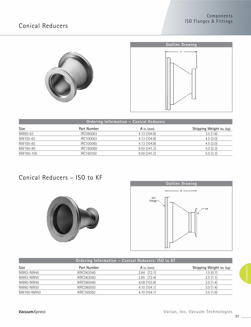
ComponentsISO F langes & Fitt ings
Conical Reducers
Conical Reducers – ISO to KF
91Varian, Inc. Vacuum Technologies
Com
pone
nts
Outline Drawing
Size Part Number A in. (mm) Shipping Weight lbs. (kg)
NW80-63 IRC080063 4.13 (104.9) 3.5 (1.6)NW100-63 IRC100063 4.13 (104.9) 4.5 (2.0)NW100-80 IRC100080 4.13 (104.9) 4.5 (2.0)NW160-80 IRC160080 9.50 (241.3) 5.0 (2.3)NW160-100 IRC160100 9.50 (241.3) 5.0 (2.3)
Ordering Information – Conical Reducers
Outline Drawing
Size Part Number A in. (mm) Shipping Weight lbs. (kg)
NW63-NW40 IKRC063040 2.84 (72.1) 1.5 (0.7)NW63-NW50 IKRC063050 2.85 (72.4) 2.5 (1.1)NW80-NW40 IKRC080040 4.09 (103.9) 3.0 (1.4)NW80-NW50 IKRC080050 4.10 (104.1) 3.0 (1.4)NW100-NW50 IKRC100050 4.10 (104.1) 3.5 (1.6)
Ordering Information – Conical Reducers: ISO to KF
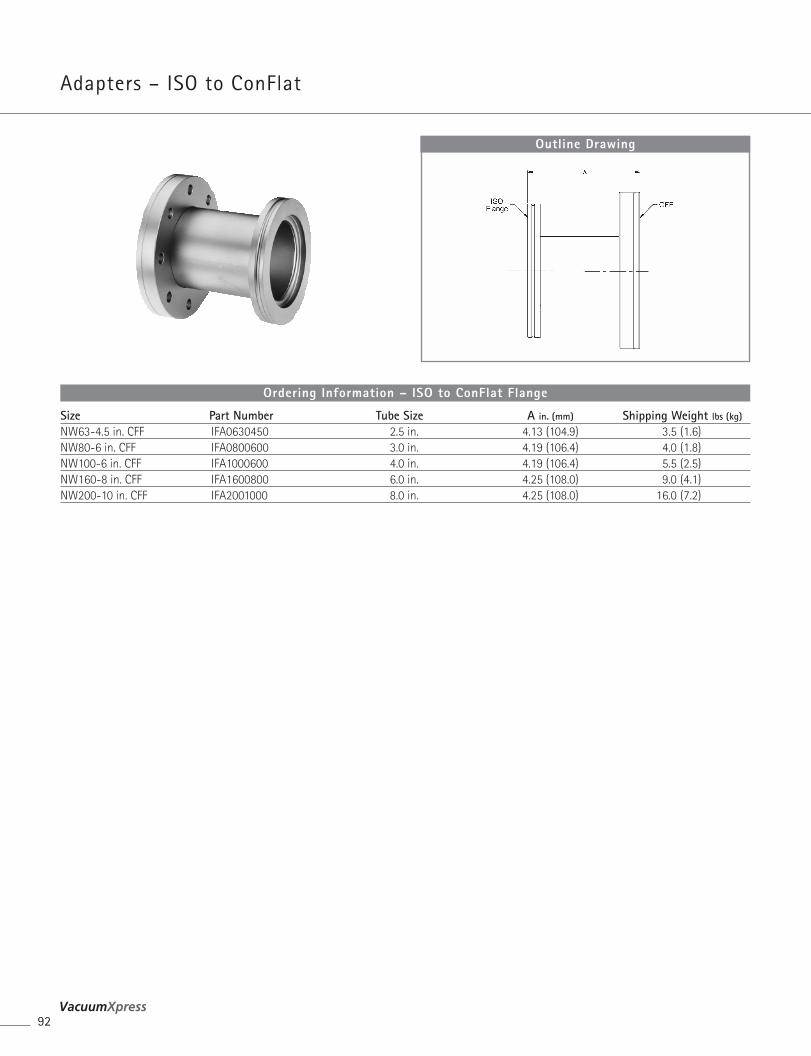
Adapters – ISO to ConFlat
92
Outline Drawing
Size Part Number Tube Size A in. (mm) Shipping Weight lbs (kg)
NW63-4.5 in. CFF IFA0630450 2.5 in. 4.13 (104.9) 3.5 (1.6)NW80-6 in. CFF IFA0800600 3.0 in. 4.19 (106.4) 4.0 (1.8)NW100-6 in. CFF IFA1000600 4.0 in. 4.19 (106.4) 5.5 (2.5)NW160-8 in. CFF IFA1600800 6.0 in. 4.25 (108.0) 9.0 (4.1)NW200-10 in. CFF IFA2001000 8.0 in. 4.25 (108.0) 16.0 (7.2)
Ordering Information – ISO to ConFlat Flange
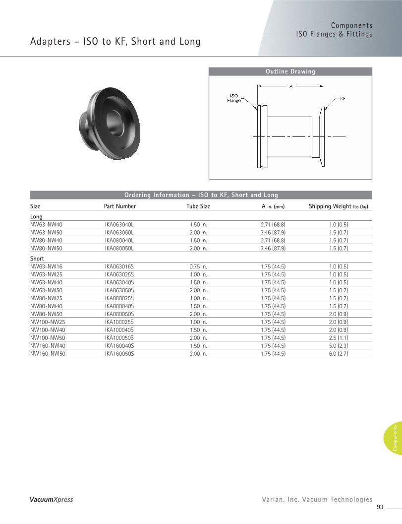
ComponentsISO F langes & Fitt ings
Adapters – ISO to KF, Short and Long
93Varian, Inc. Vacuum Technologies
Com
pone
nts
Outline Drawing
Size Part Number Tube Size A in. (mm) Shipping Weight lbs (kg)
LongNW63-NW40 IKA063040L 1.50 in. 2.71 (68.8) 1.0 (0.5)NW63-NW50 IKA063050L 2.00 in. 3.46 (87.9) 1.5 (0.7)NW80-NW40 IKA080040L 1.50 in. 2.71 (68.8) 1.5 (0.7)NW80-NW50 IKA080050L 2.00 in. 3.46 (87.9) 1.5 (0.7)
ShortNW63-NW16 IKA063016S 0.75 in. 1.75 (44.5) 1.0 (0.5)NW63-NW25 IKA063025S 1.00 in. 1.75 (44.5) 1.0 (0.5)NW63-NW40 IKA063040S 1.50 in. 1.75 (44.5) 1.0 (0.5)NW63-NW50 IKA063050S 2.00 in. 1.75 (44.5) 1.5 (0.7)NW80-NW25 IKA080025S 1.00 in. 1.75 (44.5) 1.5 (0.7)NW80-NW40 IKA080040S 1.50 in. 1.75 (44.5) 1.5 (0.7)NW80-NW50 IKA080050S 2.00 in. 1.75 (44.5) 2.0 (0.9)NW100-NW25 IKA100025S 1.00 in. 1.75 (44.5) 2.0 (0.9)NW100-NW40 IKA100040S 1.50 in. 1.75 (44.5) 2.0 (0.9)NW100-NW50 IKA100050S 2.00 in. 1.75 (44.5) 2.5 (1.1)NW160-NW40 IKA160040S 1.50 in. 1.75 (44.5) 5.0 (2.3)NW160-NW50 IKA160050S 2.00 in. 1.75 (44.5) 6.0 (2.7)
Ordering Information – ISO to KF, Short and Long
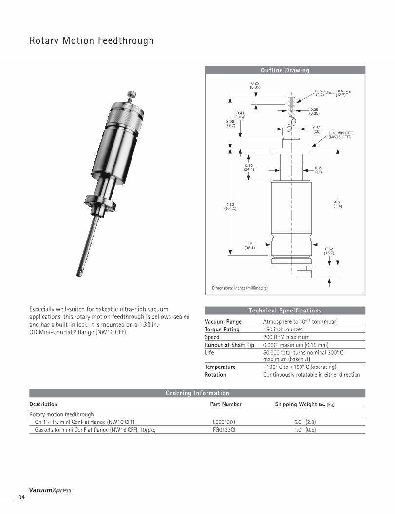
Rotary Motion Feedthrough
94
Description Part Number Shipping Weight lbs. (kg)
Rotary motion feedthroughOn 11⁄3 in. mini ConFlat flange (NW16 CFF) L6691301 5.0 (2.3)Gaskets for mini ConFlat flange (NW16 CFF), 10/pkg FG0133CI 1.0 (0.5)
Ordering Information
0.62(15.7)
4.50(114)
1.5(38.1)
4.10(104.1)
0.75(19)
0.96(24.4)
0.41(10.4)
3.06(77.7)
0.25(6.35)
9.63(16)
0.25(6.35)
0.096(2.4)
dia. x 0.5(12.7)
DP
1.33 Mini CFF(NW16 CFF)
Outline Drawing
Dimensions: inches (millimeters)
Especially well-suited for bakeable ultra-high vacuumapplications, this rotary motion feedthrough is bellows-sealedand has a built-in lock. It is mounted on a 1.33 in. OD Mini-ConFlat® flange (NW16 CFF).
Vacuum Range Atmosphere to 10-11 torr (mbar) Torque Rating 150 inch-ouncesSpeed 200 RPM maximumRunout at Shaft Tip 0.006” maximum (0.15 mm)Life 50,000 total turns nominal 300° C
maximum (bakeout)Temperature –196° C to +150° C (operating)Rotation Continuously rotatable in either direction
Technical Specifications
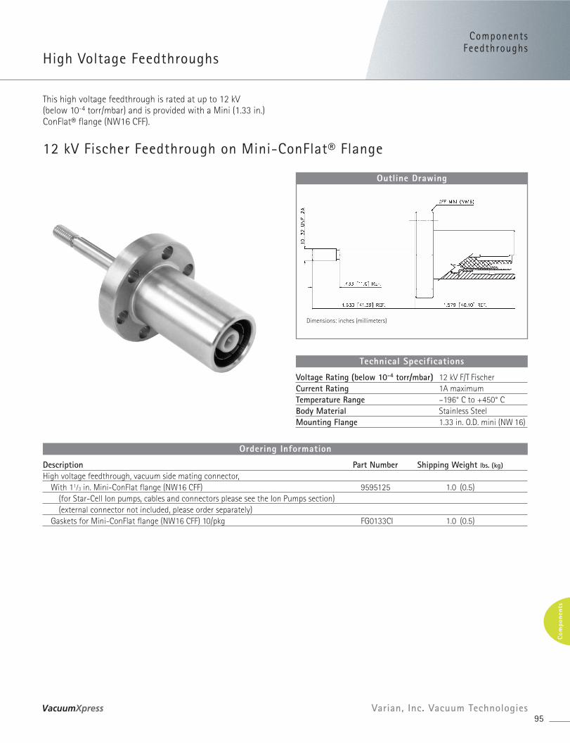
12 kV Fischer Feedthrough on Mini-ConFlat® Flange
ComponentsFeedthroughs
High Voltage Feedthroughs
95Varian, Inc. Vacuum Technologies
Com
pone
nts
Description Part Number Shipping Weight lbs. (kg)
High voltage feedthrough, vacuum side mating connector,With 11⁄3 in. Mini-ConFlat flange (NW16 CFF) 9595125 1.0 (0.5)
(for Star-Cell Ion pumps, cables and connectors please see the Ion Pumps section)(external connector not included, please order separately)
Gaskets for Mini-ConFlat flange (NW16 CFF) 10/pkg FG0133CI 1.0 (0.5)
Ordering Information
Outline Drawing
Dimensions: inches (millimeters)
This high voltage feedthrough is rated at up to 12 kV (below 10-4 torr/mbar) and is provided with a Mini (1.33 in.)ConFlat® flange (NW16 CFF).
Voltage Rating (below 10-4 torr/mbar) 12 kV F/T FischerCurrent Rating 1A maximumTemperature Range –196° C to +450° CBody Material Stainless SteelMounting Flange 1.33 in. O.D. mini (NW 16)
Technical Specifications
Supplies
96
Supplies Page
Greases and lubricants...................................................................... 97Mechanical pump fluids ................................................................... 98
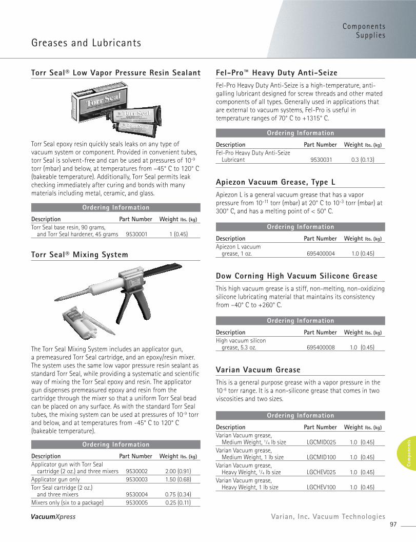
ComponentsSuppl ies
Greases and Lubricants
97Varian, Inc. Vacuum Technologies
Com
pone
nts
Torr Seal® Low Vapor Pressure Resin Sealant
Torr Seal® Mixing System
Torr Seal epoxy resin quickly seals leaks on any type ofvacuum system or component. Provided in convenient tubes,torr Seal is solvent-free and can be used at pressures of 10-9
torr (mbar) and below, at temperatures from –45° C to 120° C(bakeable temperature). Additionally, Torr Seal permits leakchecking immediately after curing and bonds with manymaterials including metal, ceramic, and glass.
Fel-Pro™ Heavy Duty Anti-SeizeFel-Pro Heavy Duty Anti-Seize is a high-temperature, anti-galling lubricant designed for screw threads and other matedcomponents of all types. Generally used in applications thatare external to vacuum systems, Fel-Pro is useful intemperature ranges of 70° C to +1315° C.
Apiezon Vacuum Grease, Type LApiezon L is a general vacuum grease that has a vaporpressure from 10-11 torr (mbar) at 20° C to 10-3 torr (mbar) at300° C, and has a melting point of < 50° C.
Varian Vacuum GreaseThis is a general purpose grease with a vapor pressure in the 10-6 torr range. It is a non-silicone grease that comes in two viscosities and two sizes.
The Torr Seal Mixing System includes an applicator gun, a premeasured Torr Seal cartridge, and an epoxy/resin mixer.The system uses the same low vapor pressure resin sealant asstandard Torr Seal, while providing a systematic and scientificway of mixing the Torr Seal epoxy and resin. The applicatorgun dispenses premeasured epoxy and resin from thecartridge through the mixer so that a uniform Torr Seal beadcan be placed on any surface. As with the standard Torr Sealtubes, the mixing system can be used at pressures of 10-9 torrand below, and at temperatures from -45° C to 120° C(bakeable temperature).
Description Part Number Weight lbs. (kg)
Torr Seal base resin, 90 grams, and Torr Seal hardener, 45 grams 9530001 1 (0.45)
Ordering Information
Description Part Number Weight lbs. (kg)
Fel-Pro Heavy Duty Anti-Seize Lubricant 9530031 0.3 (0.13)
Ordering Information
Description Part Number Weight lbs. (kg)
Apiezon L vacuumgrease, 1 oz. 695400004 1.0 (0.45)
Ordering Information
Dow Corning High Vacuum Silicone GreaseThis high vacuum grease is a stiff, non-melting, non-oxidizing silicone lubricating material that maintains its consistencyfrom –40° C to +260° C.
Description Part Number Weight lbs. (kg)
High vacuum silicongrease, 5.3 oz. 695400008 1.0 (0.45)
Ordering Information
Description Part Number Weight lbs. (kg)
Applicator gun with Torr Seal cartridge (2 oz.) and three mixers 9530002 2.00 (0.91)
Applicator gun only 9530003 1.50 (0.68)Torr Seal cartridge (2 oz.)
and three mixers 9530004 0.75 (0.34)Mixers only (six to a package) 9530005 0.25 (0.11)
Ordering Information
Description Part Number Weight lbs. (kg)
Varian Vacuum grease, Medium Weight, 1⁄4 lb size LGCMID025 1.0 (0.45)
Varian Vacuum grease, Medium Weight, 1 lb size LGCMID100 1.0 (0.45)
Varian Vacuum grease, Heavy Weight, 1⁄4 lb size LGCHEV025 1.0 (0.45)
Varian Vacuum grease, Heavy Weight, 1 lb size LGCHEV100 1.0 (0.45)
Ordering Information
Diffusion and Mechanical Pump FluidsExact diffusion pump fluid charges are now available!
98
Varian offers a wide range of diffusion pump fluid types and container sizes. We have just the right fluid type andcontainer size to meet the requirements of your particularapplication. Varian now offers exact pump charges for manyof our diffusion pumps, including the VHS-6, VHS-10, HS-16,
HS-20, HS-32, and NHS-35. Exact pump charges enables youto purchase just enough fluid to fill your diffusion pump,thus eliminating costly waste. This eliminates problemsassociated with the disposal of diffusion pump fluid, andeliminates the guess work associated with filling the pump.
Varian Oil, GP Type Mechanical Pump FluidVarian GP Type Fluid is a mechanical pump fluidrecommended for use in non-corrosive applications. As aresult of molecular distillation, it has low vapor pressure and,therefore, backstreams less than undistilled refinery products.
Description Diffusion Pump Exact Charge Part Number Shipping Weight lbs. (kg)
NEOVAC SY*1 liter/1,000 cc VHS-10, VHS-400 K6948301 3.0 (1.4)1 U.S. gallon (3.8 liters) K6948305 10.6 (4.8)5 U.S. gallons (18.9 liters) K6948315 53.0 (23.9)
Dow Corning DC-702*500 cc VHS-6, VHS-250 695472005 3.0 (1.4)1 U.S. gallon (3.8 liters) 695472008 12.0 (5.4)5 U.S. gallons (18.9 liters) 695472015 51.0 (23.0)
Dow Corning DC-704*500 cc VHS-6, VHS-250 695474005 3.0 (1.4)1 U.S. gallon (3.8 liters) 695474008 12.0 (5.4)6.2 U.S. gallons (23.5 liters) 695474015 51.0 (23.0)
Dow Corning DC-705*500 cc VHS-6, VHS-250 695475005 3.0 (1.4)1 U.S. gallon (3.8 liters) 695475008 12.0 (5.4)
Santovac 540 cc 695405001 1.0 (0.5)65 cc 695405002 2.0 (0.9)500 cc VHS-6, VHS-250 695405005 2.5 (1.1)* For technical information, refer to the Diffusion Pump Section page 30.
Ordering Information
Description Part Number Shipping Weight lbs. (kg)1 liter bottle K7516301 3.5 (1.6)1 gallon bottle K7516302 14.0 (6.4)
Ordering Information