Embed Size (px)
DESCRIPTION
This is a document that guide for operating Varian GC 430
Citation preview

Varian BV Herculesweg 8 4330 EA Middelburg The Netherlands
430-GC and 431-GC
User Manual North/South America 2700 Mitchell Drive Walnut Creek 94598 California, USA Tel: ++(1)9259392400 Fax: ++(1)9259452360 or ++(1)9259452344
Europe P.O. Box 8033 4330 EA Middelburg The Netherlands Tel: ++(31)118671000 Fax: ++(31)118623193
Australia/East Asia 679 Springvale Road Mulgrave, Victoria 3171 Australia Tel: ++(61)395607133 Fax: ++(61)395607950
© 2008 Varian, Inc. All Rights Reserved Printed in the Netherlands CP501406 Rev: February 7, 2008

Warranty
Page:II User Manual 430-GC and 431-GC Varian, Inc.
Read Before Operating Important Safeguards
The following items are frequently not recognized or are overlooked by new users while learning to operate a GC or a GC/MS. They are brought to your attention to safeguard against damage to your equipment.
Carrier gas must be flowing through the column before heating the column oven. Carefully evaluate columns that have been heated with no carrier gas flowing through and discard, if damaged. Ensure the injector contains a septum and there is a positive flow of carrier gas before heating the column. The column outlet in a GC/MS system is at a vacuum. Do not use columns which are wide bore and short in length with constant flow at low flow rates since the inlet pressure may be less than the ambient 1 atmosphere. An inlet pressure less than ambient will be indicated as a negative pressure. If the required pressure is less than 1 atmosphere, the system will try to adjust the pressure to the calculated value. Since the split vent and septum purge valve vent to the lab, the vacuum pump will draw air through your column potentially ruining the column and damaging your MS detector if installed.
Important Tips Regarding 430-GC and 431-GC Operation
After editing the active method, it must be re-activated before running the next analysis. Always remember to activate a method after you have made edits, if you intend to run that method next. The 431-GC is sold with Varian Mass Spectrometers and is controlled through the MS Workstation Software. Since the 431-GC is part of an integrated GC/MS, the Local User Interface (LUI) and keyboard are not required. The 431-GC supports one active method at a time. You may build and edit GC methods using the MS Workstation while the GC is running but you may not change the method that is currently running. If you are using the 430-GC, you may edit methods locally only when the GC is not in the RUN state (executing a method). The Status and Control screen for the 430-GC has an extend runtime key that will allow you to extend the runtime by 10 minutes each time you click on the key. The extended run time will be used until the method is either re-activated or a new method is activated. The extend run feature does not change the method stored in your Workstation. If a potentially hazardous Error is detected, such as a thermal runaway, the 430-GC shuts down the affected component and reports the Error. After correcting the Error, normal operation is restored by powering the 430-GC OFF then ON.
Warranty
Varian, Inc. User Manual 430-GC and 431-GC Page: III
VARIAN ANALYTICAL INSTRUMENT WARRANTY HARDWARE PRODUCTS All analytical instruments sold by Varian are warranted to be free from defects in material and workmanship for the periods specified and in accordance with the terms on the face of Varian's quotation or as otherwise agreed upon in writing between Varian and the Customer. The warranty period begins on the date of shipment from Varian to the original Customer. However, where installation is paid for by the Customer or included in the purchase price, the warranty period begins upon completion of installation. If the Customer schedules installation to start later than 30 days after delivery or if such delay is caused through the Customer's inability to provide adequate facilities or utilities or through failure to comply with Varian's reasonable pre-installation instructions or through other omissions by Customer, then the warranty period starts on the 31st day from date of shipment. Moreover Varian will charge the Customer for labor and other expenses involved in making multiple or follow-up installation service calls.
SOFTWARE PRODUCTS Where software is provided within the frame of a license agreement concluded between the Customer and Varian, any warranty shall be strictly in accordance with the terms of such agreement. In the absence of a license agreement and unless an alternate warranty period is agreed upon in writing between Varian and the Customer, the warranty period is as specified on the face of Varian's quotation. Varian warrants such software products, if used with and properly installed on Varian hardware or other hardware as specified by Varian to perform as described in the accompanying Operator's Manual and to be substantially free of those defects which cause failure to execute respective programming instructions; however, Varian does not warrant uninterrupted or error-free operation.
REMEDIES The sole and exclusive remedy under hardware warranty shall be repair of instrument malfunctions which in Varian's opinion are due or traceable to defects in original materials or workmanship or, at Varian's option, replacement of the respective defective parts, provided that Varian may as an alternative elect to refund an equitable portion of the purchase price of the instrument or accessory. Repair or replacement under warranty does not extend the original warranty period. Repair or replacement under warranty claims shall be made in Varian's sole discretion either by sending a Customer Support Representative to the site or by authorizing the Customer to return the defective accessory or instrument to Varian or to send it to a designated service facility. The Customer shall be responsible for loss or damage in transit and shall prepay shipping cost. Varian will return the accessory or instrument to the Customer prepaid and insured. Claims for loss or damage in transit shall be filed by the Customer. To correct software operation anomalies, Varian will issue software revisions where such revisions exist and where, in Varian's opinion, this is the most efficient remedy.
LIMITATION OF WARRANTY This warranty does not cover software supplied by the Customer, equipment and software warranted by another manufacturer or replacement of expendable items and those of limited life, such as but not limited to: Filters, glassware, instrument status lamps, source lamps, septa, columns, fuses, chart paper and ink, nebulizers, flow cells, pistons, seals, fittings, valves, burners, sample tubes, probe inserts, print heads, glass lined tubing, pipe and tube fittings, variable temperature dewars, transfer lines, flexible discs, magnetic tape cassettes, electron multipliers, filaments, vacuum gaskets, seats and all parts exposed to samples and mobile phases. This warranty shall be void in the event of accident, abuse, alteration, misuse, neglect, breakage, improper operation or maintenance, unauthorized or improper modifications or tampering, use in an unsuitable physical environment, use with a marginal power supply or use with other inadequate facilities or utilities. Reasonable care must be used to avoid hazards. This warranty is expressly in lieu of and excludes all other express or implied warranties, including but not limited to warranties of merchantability and of fitness for particular purpose, use or application, and all other obligations or liabilities on the part of Varian, unless such other warranties, obligations or liabilities are expressly agreed to in writing by Varian.
LIMITATION OF REMEDIES AND LIABILITY The remedies provided herein are the sole and exclusive remedies of the Customer. In no case will Varian be liable for incidental or consequential damages, loss of use, loss of production or any other loss incurred.

Safety Information
Page: IV User Manual 430-GC and 431-GC Varian, Inc.
SAFETY INFORMATION
INFORMATION To prevent any injury to the user or any damage to the instrument it is essential that you read the information in this chapter and the GC user manual(s). If this manual is not in your native language and if you have problems understanding the text, we advise you to contact your Varian office for assistance. Varian cannot accept responsibility for any damage or injury caused by misunderstanding of the information in this manual.
OPERATING INSTRUCTIONS This instruction manual is provided to help you establish operating conditions, which will permit safe and efficient use of your equipment. Special considerations and precautions are also described in the manual, which appear in the form of NOTES, CAUTIONS, and WARNINGS as described below (next page). It is important that you operate your equipment in accordance with this instruction manual and any additional information, which may be provided by Varian. Address any questions regarding the safe and proper use of your equipment to your local Varian office.

Safety Information
Varian, Inc. User Manual 430-GC and 431-GC Page: V
Information to aid you in obtaining optimal performance from your instrument.
Alerts you to situations that may cause moderate injury and/or equipment damage, and how to avoid these situations.
Alerts you to potentially hazardous situations that could result in serious injury, and how to avoid these situations.
Warning Symbol Warning Description
Hazardous voltages are present inside instrument. Disconnect from main power before removing screw-attached panels.
Hazardous chemicals may be present. Avoid contact, especially when replenishing reservoirs. Use proper eye and skin protection.
Very hot or cryogenically cold surfaces may be exposed. Use proper skin protection.
Eye damage could occur either from flying particles, chemicals, or UV radiation. Use proper eye and face protection.
The potential for fire may be present. Follow manual instructions for safe operation.
The potential for explosion may exist because of type of gas or liquid used.
Ionizing radiation source is present. Follow manual instructions for safe operation.
Keep hands and fingers away.

Safety Information
Page: VI User Manual 430-GC and 431-GC Varian, Inc.
GENERAL SAFETY PRECAUTIONS Follow these safety practices to ensure safe equipment operation.
Perform periodic leak checks on all supply lines and pneumatic plumbing.
Do not allow gas lines to become kinked or punctured. Place lines away from foot traffic and extreme heat or cold.
Store organic solvents in fireproof, vented and clearly labeled cabinets so they are easily identified as toxic and/or flammable materials.
Do not accumulate waste solvents. Dispose of such materials through a regulated disposal program and not through municipal sewage lines.
This instrument has been tested per applicable requirements of EMC Directive as required to carry the European Union CE Mark. As such, this equipment may be susceptible to radiation/interference levels or frequencies which are not within the tested limits.
This instrument is designed for chromatographic analysis of appropriately prepared samples. It must be operated using appropriate gases and/or solvents and within specified maximum ranges for pressure, flows, and temperatures as described in this manual. If the equipment is used in a manner not specified by the manufacturer, the protection provided by the equipment may be impaired.
It is the responsibility of the Customer to inform Varian Customer Support Representatives if the instrument has been used for the analysis of hazardous biological, radioactive, or toxic samples, prior to any instrument service being performed or when an instrument is being returned to the Service Center for repair.

Safety Information
Varian, Inc. User Manual 430-GC and 431-GC Page: VII
ELECTRICAL HAZARDS
Disconnect the instrument from all power sources before removing protective panels to avoid exposure to potentially dangerous voltages.
When it is necessary to use a non-original power cord plug, make sure the replacement cord adheres to the color coding and polarity described in the manual and all local building safety codes.
Replace blown fuses with fuses of the size and rating stipulated on the fuse panel or in the manual.
Make sure that voltage sources and line voltage match the value for which the instrument is wired.
Replace faulty or frayed power cords immediately with the same type and rating.
COMPRESSED GAS CYLINDERS
Store and handle compressed gases carefully and in strict adherence to safety codes.
Secure cylinders to an immovable structure or wall. Store and move cylinders in an upright, vertical position.
Before transport, remove regulators and install cylinder cap. Store cylinders in a well-ventilated area away from heat,
direct sunshine, freezing temperatures, and ignition sources. Mark cylinders clearly so there is no doubt as to their
contents. Use only approved regulators and connections. Use only connector tubing that is chromatographically clean
(Varian Part Number 03-918326-00) and has a pressure rating significantly greater than the highest outlet pressure from the regulator.

Safety Information
Page: VIII User Manual 430-GC and 431-GC Varian, Inc.
GC SAFETY PRACTICES
Exhaust System No special exhaust ducting is necessary for GC detectors installed in a well-ventilated room except when the detectors are used to test hazardous chemicals. If you do install ducting:
Use only fireproof ducting. Install a blower at the duct outlet. Secure air duct intakes such that their vibration or air movement
does not effect detector operation. Check periodically for proper operation of the duct. Ensure proper ventilation in lab area.
Radioactive Source Detectors
Read carefully and comply with all NOTES, CAUTIONS, and WARNINGS in the Ni63 ECD manual. Perform the tests for removable radioactive contamination described in the Ni63 ECD manual. Comply with leak test schedules and procedures.
Burn Hazard Heated or cryogenically cooled zones of the GC can remain hot or cold for a considerable time after instrument power is turned off. To prevent painful burns, ensure that all heated or cooled areas have returned to room temperature or wear adequate hand protection before you touch potentially hot or cold surfaces.

Safety Information
Varian, Inc. User Manual 430-GC and 431-GC Page: IX
SPARE PARTS AVAILABILITY It is the policy of Varian to provide operational spare parts for any instrument and major accessory for a period of five (5) years after shipment of the final production run of that instrument. Spare parts will be available after this five (5) year period but on an as available basis. Operational spare parts are defined as those individual electrical or mechanical parts that are susceptible to failure during their normal operation. Examples include relays, lamps, temperature probes, detector elements, motors, etc. Sheet metal parts, structural members or assemblies and castings, printed circuit boards, and functional modules are normally capable of being rebuilt to like-new condition throughout their useful life and therefore will be supplied only on an as available basis after the final production run of the instrument.
SERVICE AVAILABILITY Varian provides a variety of services to support its customers after warranty expiration. Repair service can be provided by attractively priced service contracts or on a time and material basis. Technical support and training can be provided by qualified personnel on both a contractual or as-needed basis.
Varian Analytical Instruments Sales Offices For Sales or Service assistance and to order Parts and Supplies, contact your local Varian office. Argentina Buenos Aires Tel. +54.11.4.783.5306 Australia Mulgrave, Victoria Tel. +61. 3.9560.7133 Austria Poettelsdorf Tel. +43.2626.20090 Benelux Middelburg Tel. +31.118.671500 Brazil and Latin America (S) São Paulo Tel. +55.11.3845.0444 Canada Mississauga, Ontario Tel. 800.387.2216 China Beijing Tel. +86.106310.8550 Europe Middelburg, The Netherlands Tel. +31.118.671.000
France Les Ulis Cédex Tel. +33.1.6986.3838 Germany Darmstadt Tel. +49.6151.7030 India Mumbai Tel. +91.22.2570.8595/97 Italy Torino Tel. +39.011.997.9111 Japan Tokyo Tel. +81.3.5232.1239 Korea Seoul Tel. +82.333.665.5171 Mexico and Latin America (N) Mexico City Tel. +52.5.55.5239465/026
Russian Federation Moscow Tel. +7.095.937.4280 Spain Madrid Tel. +34.91.472.7612 Sweden Solna Tel. +46.8.445.1620 Switzerland Steinhausen Tel. +41.848.803.800 Taiwan Shih-Chi Tel. +886.22.698.9555 United Kingdom and Ireland Oxford Tel. +44.1865.291500 Venezuela Caracas Tel. +58.212.285.0320/2494
United States
Walnut Creek, California, USA Tel. +1.800.926.3000 (GC and GC/MS)
Tel. +1.800.367.4752 (LC)
http://www.varianinc.com/

Safety Information
Page: X User Manual 430-GC and 431-GC Varian, Inc.

Table of Contents
Varian, Inc. User Manual 430-GC and 431-GC Page: 1
Table of Contents VARIAN ANALYTICAL INSTRUMENT WARRANTY................................................................... III
HARDWARE PRODUCTS ..........................................................................................................................III SOFTWARE PRODUCTS............................................................................................................................III REMEDIES...............................................................................................................................................III LIMITATION OF WARRANTY ...................................................................................................................III LIMITATION OF REMEDIES AND LIABILITY .............................................................................................III
SAFETY INFORMATION..................................................................................................................... IV INFORMATION.........................................................................................................................................IV OPERATING INSTRUCTIONS ....................................................................................................................IV GENERAL SAFETY PRECAUTIONS ...........................................................................................................VI ELECTRICAL HAZARDS......................................................................................................................... VII COMPRESSED GAS CYLINDERS............................................................................................................. VII GC SAFETY PRACTICES.......................................................................................................................VIII
Exhaust System .............................................................................................................................. VIII Radioactive Source Detectors........................................................................................................ VIII Burn Hazard .................................................................................................................................. VIII
SPARE PARTS AVAILABILITY..................................................................................................................IX SERVICE AVAILABILITY .........................................................................................................................IX
ABOUT YOUR 431-GC.............................................................................................................................6
ABOUT YOUR 430-GC.............................................................................................................................6 KEYPAD....................................................................................................................................................7
INSTALLATION .....................................................................................................................................10 NOTES ABOUT SETTING UP AND USING YOUR 430-GC .........................................................................10 PREPARING FOR INSTALLATION..............................................................................................................10 INSTALLING THE CP-8400/8410 AUTOSAMPLER....................................................................................11
Mounting the CP-8400/8410 onto the 430-GC.................................................................................11 Connecting AutoSampler Power and Communication Cables..........................................................12
430-GC REAR-PANEL CONNECTORS......................................................................................................13 Connector J2 Sync/Analog Out.........................................................................................................14 Connector J22 External Events.........................................................................................................15 Column Installation ..........................................................................................................................16 Column Length and Dimension Procedure.......................................................................................16 Preparing Column Ends ...................................................................................................................17
CONNECTING GASES ..............................................................................................................................19 Connecting Gases .............................................................................................................................19
SETUP INFORMATION..............................................................................................................................20 ETHERNET COMMUNICATIONS ...............................................................................................................20
Network Terminology .......................................................................................................................23 Loading the Appropriate Software onto your Workstation PC.........................................................24
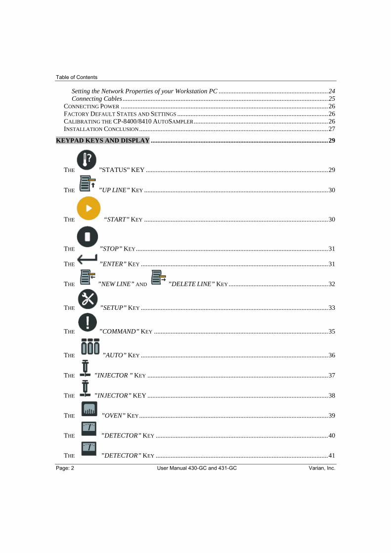
Table of Contents
Page: 2 User Manual 430-GC and 431-GC Varian, Inc.
Setting the Network Properties of your Workstation PC ..................................................................24 Connecting Cables............................................................................................................................25
CONNECTING POWER .............................................................................................................................26 FACTORY DEFAULT STATES AND SETTINGS ...........................................................................................26 CALIBRATING THE CP-8400/8410 AUTOSAMPLER.................................................................................26 INSTALLATION CONCLUSION..................................................................................................................27
KEYPAD KEYS AND DISPLAY ...........................................................................................................29
THE ”STATUS” KEY ..............................................................................................................29
THE ”UP LINE” KEY ...............................................................................................................30
THE “START” KEY ...............................................................................................................30
THE ”STOP” KEY....................................................................................................................31
THE ”ENTER” KEY .................................................................................................................31
THE ”NEW LINE” AND ”DELETE LINE” KEY............................................................32
THE ”SETUP” KEY .................................................................................................................33
THE ”COMMAND” KEY .........................................................................................................35
THE ”AUTO” KEY .................................................................................................................36
THE ”INJECTOR ” KEY .............................................................................................................37
THE ”INJECTOR” KEY .............................................................................................................38
THE ”OVEN” KEY..................................................................................................................39
THE ”DETECTOR” KEY ........................................................................................................40
THE ”DETECTOR” KEY ........................................................................................................41
Table of Contents
Varian, Inc. User Manual 430-GC and 431-GC Page: 3
THE ”AUTO” KEY....................................................................................................................42 MAINTENANCE, PARTS AND SUPPLIES.........................................................................................43
GENERAL GC MAINTENANCE.................................................................................................................44 Checking and Renewing Gas Supplies..............................................................................................44 Leak Checking...................................................................................................................................44 Gas Filter Cartridge Replacement....................................................................................................46
INJECTOR MAINTENANCE .......................................................................................................................46 Septum Replacement .........................................................................................................................48 Insert Replacement ...........................................................................................................................49
Removing the Glass Insert ........................................................................................................................... 49 Inserting the Glass Insert.............................................................................................................................. 50
Pencil Filter ......................................................................................................................................51 THE 1177 SPLIT/SPLITLESS CAPILLARY INJECTOR..................................................................................53
Features of the 1177 injector ............................................................................................................54 Automatic Start Switch......................................................................................................................54 1177 Injector Inserts .........................................................................................................................54 1177 Modes of Injection....................................................................................................................55
Split Mode.................................................................................................................................................... 55 Splitless Mode.............................................................................................................................................. 55
1177 Electronic Flow Control (EFC) ...............................................................................................56 1177 Manual Pneumatics .................................................................................................................59 Operation of the 1177 Injector..........................................................................................................59
Column Installation ...................................................................................................................................... 59 Condition the Column .................................................................................................................................. 59 Column Installation in Detector ................................................................................................................... 59
Setting 1177 Gas Flow Rates ............................................................................................................60 EFC Pneumatics ...............................................................................................................................60 Septum Purge Calibration ................................................................................................................61 Manual Pneumatics ..........................................................................................................................62
Tools and equipment needed........................................................................................................................ 62 1177 Modes of Operation .................................................................................................................63
Split Injection............................................................................................................................................... 63 Splitless Injection..............................................................................................................................64 1177 Injector Assembly.....................................................................................................................65 Maintenance......................................................................................................................................66
Tools Required ............................................................................................................................................. 66 Remove the Glass Insert....................................................................................................................66 Replace the Glass Insert ...................................................................................................................67 Injector body cleaning ......................................................................................................................68
THE 1041 ON-COLUMN INJECTOR ..........................................................................................................71 Automatic Start Switch......................................................................................................................72 Injector Assembly and Insert ............................................................................................................73 Column Installation ..........................................................................................................................74
Column connection to Injector ..................................................................................................................... 74 1041 Electronic Flow Control ..........................................................................................................75
Setting the Carrier Gas Flow ........................................................................................................................ 76 Flow Rates for Operation ............................................................................................................................. 77 Capillary Mode............................................................................................................................................. 77
Table of Contents
Page: 4 User Manual 430-GC and 431-GC Varian, Inc.
Testing the 1041 Injector ..................................................................................................................77 DETECTOR CONNECTIONS AND HARDWARE...........................................................................................78 THE FID DETECTOR ...............................................................................................................................79
Installation/Disassembly...................................................................................................................80 Exploded View............................................................................................................................................. 80
Disassemble the FID.........................................................................................................................81 Reassemble the FID ..........................................................................................................................82
THERMAL CONDUCTIVITY DETECTOR (TCD).........................................................................................85 Initial Set-Up.....................................................................................................................................86 TCD Adjustments ..............................................................................................................................87
Setting the Filament Temperature Limit ...................................................................................................... 87 Operation..........................................................................................................................................88
Before Operating the TCD ........................................................................................................................... 88 Range Setting ............................................................................................................................................... 89 Low Currents (100-150 mA)........................................................................................................................ 90 High Currents (300 mA)............................................................................................................................... 91 Calculate Detector Sensitivity ...................................................................................................................... 91 Calculate Detector Detectivity ..................................................................................................................... 92 Reverse Polarity ........................................................................................................................................... 92
Adjust TCD Carrier Gas Flow Rates................................................................................................92 ERRORS ..................................................................................................................................................93
SHIPPING, CLEANING AND DISPOSAL INSTRUCTIONS............................................................99 SHIPPING INSTRUCTIONS ........................................................................................................................99 CLEANING INSTRUCTIONS ......................................................................................................................99 DISPOSAL INSTRUCTIONS .......................................................................................................................99
REPLACEMENT PARTS.....................................................................................................................101

Table of Contents
Varian, Inc. User Manual 430-GC and 431-GC Page: 5
Figures FIGURE 1: AUTOSAMPLER CP-8400/8410 ON THE 430-GC, SCREW LOCATIONS ............ 11 FIGURE 2: 430-GC REAR PANEL SHOWING CP-8400/8410 CABLING ................................ 12 FIGURE 3: 430-GC REAR-PANEL CONNECTIONS ................................................................. 13 FIGURE 4: CONNECTOR J2 SYNC/ANALOG OUT.................................................................. 14 FIGURE 5: CONNECTOR J22 EXTERNAL EVENTS ................................................................ 15 FIGURE 6: COLUMN INSERTION DEPTHS.............................................................................. 16 FIGURE 7: COLUMN ENDS ....................................................................................................... 17 FIGURE 8: PROPER FERRULE ORIENTATION...................................................................... 19 FIGURE 9: 430-GC DIRECT CONNECTED TO THE WORKSTATION..................................... 20 FIGURE 10: ISOLATED NETWORK........................................................................................... 21 FIGURE 11: COMPANY NETWORK .......................................................................................... 22 FIGURE 12: TABLE OPERATIONS WITH LOCAL USER INTERFACE.................................... 32 FIGURE 13: EFC21 AND 1177 IN SPLIT MODE FLOW DIAGRAM.......................................... 56 FIGURE 14: EFC21 AND 1177 IN SPLITLESS MODE FLOW DIAGRAM................................. 57 FIGURE 15: EFC25 FLOW DIAGRAM ....................................................................................... 58 FIGURE 16: 1177 INJECTOR ASSEMBLY ................................................................................ 65 FIGURE 17: 1041 UNIVERSAL INJECTOR WITH INSERT....................................................... 73 FIGURE 18: EFC23 FLOW DIAGRAM ....................................................................................... 75 FIGURE 19: EFC24 FLOW DIAGRAM ....................................................................................... 76 FIGURE 20: FID EXPLODED VIEW ........................................................................................... 80 FIGURE 21: FID TOP VIEW ....................................................................................................... 83 FIGURE 22: TCD SENSITIVITY AND AMPLIFICATION............................................................ 90
Tables TABLE 1: GENERAL TIGHTENING AND RETIGHTENING FOR COMMON FERRULES....... 18 TABLE 2: MAINTENANCE SCHEDULE ..................................................................................... 43 TABLE 3: SPLIT INJECTION TYPICAL CONDITIONS .............................................................. 63 TABLE 4: SPLITLESS INJECTION METHOD PARAMETERS .................................................. 64 TABLE 5: 1177 COLUMN FERRULES 1/16".............................................................................. 65 TABLE 6: 1041 COLUMN FERRULES 1/16" X 0.8 MM ............................................................. 73 TABLE 7: CARRIER GAS FLOW RATES FOR 1041................................................................. 77 TABLE 8: 1041 TEST COMPOUNDS......................................................................................... 77

Introduction
Page: 6 User Manual 430-GC and 431-GC Varian, Inc.
ABOUT YOUR 431-GC The 431-GC is sold with Varian Mass Spectrometers and is controlled through the MS Workstation. Since the 431-GC is part of an integrated GC/MS, the Local User Interface (LUI) and keyboard are not required. The information in the manual regarding the 430-GC also applies to the 431-GC, with the exception of the sections describing the LUI or keypad.
ABOUT YOUR 430-GC The 430-GC is designed to be a single channel to use and easy to maintain Gas Chromatograph. The Injector and Detector of the 430-GC are all electronic controlled. It may be equipped with either an 1177 split/splitless or a 1041 On-Column injector and either an FID or a TCD detector. Optionally it may have liquid CO2 column oven cryogenics, additional gas sampling valves and an Ethernet communications option. Typically the only operator interactions with the GC are to turn on the GC, put vials into the AutoSampler carrousel, change the AutoSampler syringe when required, change the column when needed, and change the injector septum when needed. Column dimensions, temperature limits, A/S position calibration and other configuration functions are entered through the 430-GC keypad, methods can be built from the Workstation and downloaded either manually or as part of an automated SampleList or Sequence or they can be built from the keypad. All electrical connections and carrier gas supply connections are made at the back of the 430-GC on page 13.

Introduction
Varian, Inc. User Manual 430-GC and 431-GC Page: 7
KEYPAD The Varian 430-GC is an all electronic, single channel gas chromatograph. The keypad relies on icons to identify the actions of the keys on the keypad on page 29.
The keys ”AUTO”, ”SETUP”, ”COMMAND”, ”INJECTOR”, ”OVEN”,
”DETECTOR” with a LED, indicate that entries underneath are present. Changing a value will not immediately result in a change of the parameter being edited. Only after pushing the ”ENTER” key the value will be accepted.
The keys ”STATUS” and ”UP LINE” only serve to change the display. If you wish to
exit a field that you have edited without accepting the edit, press the keys and to escape from that field.
The keys ”START”, ”STOP”, ”ENTER”, ”NEW LINE” and ”DELETE LINE” indicate an action will occur when that key is pressed.
and are two examples of action keys. For instance, if you press , the 430-GC will immediately begin a run (in automatic manual injections you will be prompted for the vial and method before the injection occurs).
All selections from the keypad are made via scrolling using the ”UP” and ”DOWN” keys immediately to the right of the display; it is not possible to enter an illegal value. To accept the
value press immediately. You may press either or to scroll between parameters.

Introduction
Page: 8 User Manual 430-GC and 431-GC Varian, Inc.
The display is designed to show you both data and navigational information. This is presented to you in two ways;
1. An LED will illuminate showing you which section you are working in and displaying.
2. The display will provide you direct information on where in a section you are as well as the parameter.
In the following example, the A/S indicates you are working on the AutoSampler method section, the 2 represents the current line number, and the 31 indicates the total number of lines in the A/S User Defined section. The rest of the display is composed of the parameter and its current setting. An LED next to the A/S method section will be illuminated to further affirm that you are working in the A/S method section.
While not all displays will show current line out of a total number of lines, they all follow the principle of informing you with a LED that indicates which key was selected.
The information above represents all of the fundamental interactions with the keypad.
If you are controlling your 430-GC from a WorkStation, you will need to establish Ethernet communications with the GC as described in this manual on page 20 and use your Workstation according to its instructions.

Introduction
Varian, Inc. User Manual 430-GC and 431-GC Page: 9

Installation
Page: 10 User Manual 430-GC and 431-GC Varian, Inc.
INSTALLATION
NOTES ABOUT SETTING UP AND USING YOUR 430-GC The purity of the gases used with your 430-GC are essential for optimum operation. A Varian Gas Clean Filter Kit (CP736530) must be installed. All GCs require regular maintenance in order to operate at their highest efficiency. You will want to change the injector septum, injector liner, FID flame tip, gas filters and AutoSampler vials, wash bottle septa and solvents regularly. Varian has an extensive supply of quality maintenance parts for your 430-GC and all of your chromatography needs including a comprehensive selection of the highest quality capillary columns available to chromatographers. Please visit the Varian internet site (www.varianinc.com), contact your Varian sales representative, or call your local Varian distribution center.
PREPARING FOR INSTALLATION
Refer to the Pre-Installation Instructions (CP501405) for site preparation and unpacking information.
The instrument has been protected during shipment by various caps, plugs and restraints.
Prior to operating:
Remove the tape restraining the column oven door.
Remove any plastic plugs or caps inside the column oven and of FID.
Cut the tie wrap and remove the shipping dowel for oven fan motor from the hole in the GC left side panel.
Remove the carrier gas fitting cap on the rear panel.
Install the septum purge cover by snapping it onto the GC above the oven door.

Installation
Varian, Inc. User Manual 430-GC and 431-GC Page: 11
INSTALLING THE CP-8400/8410 AUTOSAMPLER To install your CP-8400/8410 on a 430-GC, first unpack the AutoSampler and verify that all of the parts required are present. Contact your Varian representative immediately if you find that any parts are damaged or missing.
Mounting the CP-8400/8410 onto the 430-GC
The CP-8400/8410 has a single mounting position on the 430-GC top cover. There are two metal guiding pins in the bottom of the AutoSampler that fit into corresponding holes in the 430-GC top cover.
The CP-8400/8410 is attached to the top cover by securing two screws on the AutoSampler base underneath the sample tray and two more screws on a tab at the rear of the AutoSampler.
Figure 1: AutoSampler CP-8400/8410 on the 430-GC, screw locations

Installation
Page: 12 User Manual 430-GC and 431-GC Varian, Inc.
Connecting AutoSampler Power and Communication Cables The CP-8400/8410 is connected with a three connector cable (included with the Sampler) to the 430-GC.
• The 25-pin D-shell connector attaches to the S.I.D. port (J4) connector.
• The small white power connector to the A/S POWER connector (J7).
• The 15-pin D-shell connector is plugged into the back of the CP-8400/8410.
It is important that the CP-8400/8410 is switched on prior to powering up the GC. A flashing green LED at the rear of the AutoSampler is indicating that there is communication between 430-GC and the Sampler.
Figure 2: 430-GC Rear Panel Showing CP-8400/8410 Cabling

Installation
Varian, Inc. User Manual 430-GC and 431-GC Page: 13
430-GC REAR-PANEL CONNECTORS
Figure 3: 430-GC Rear-Panel Connections
J2 SYNC/Analog OutSynchronization signal connector between the GC and
External devices, see on page 14
J4 S.I.D.Serial port for CP-8400/8410 AutoSampler control
J7 A/S POWERPower Connector for CP-8400/8410 AutoSampler
J10 COMM.RJ45 connector for 10 base T cable for Ethernet
communications
J12 SERVICENot in use
J2 External Events
Timed relay contacts, see on page 15
F1 FuseUser-accessible fuse, 24 volt supply
AC Power Input
Standard power cable

Installation
Page: 14 User Manual 430-GC and 431-GC Varian, Inc.
Connector J2 Sync/Analog Out Connection between the 430-GC and External devices (Synchronization/ Analog
signals).
1
2
3
11
Ready-In *GND-1
Integrator ID *
9 Start-Out
GND-2
Analog-Out1 Volt (default)
10 VoltSelectable by Jumper
on Main-Board
Connector J2Sync/Analog-Out430-GC
7
15
1
8
9
15
Figure 4: Connector J2 Sync/Analog Out
If an integrator or other device is connected, pin-2 and 11 must be connected in order to inform the 430-GC firmware that an external device has been connected. The 430-GC is then waiting for Ready-In (pin-1) to get start permission.
*
Installation
Varian, Inc. User Manual 430-GC and 431-GC Page: 15
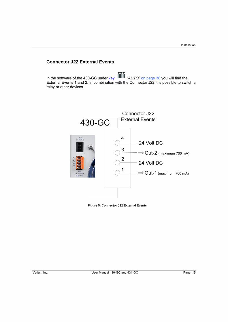
Connector J22 External Events
In the software of the 430-GC under key “AUTO” on page 36 you will find the External Events 1 and 2. In combination with the Connector J22 it is possible to switch a relay or other devices.
430-GC
1
2
3
4
Connector J22External Events
Out-1 (maximum 700 mA)
Out-2 (maximum 700 mA)
24 Volt DC
24 Volt DC
4321
Figure 5: Connector J22 External Events

Installation
Page: 16 User Manual 430-GC and 431-GC Varian, Inc.
Column Installation
Figure 6: Column Insertion Depths
Column Length and Dimension Procedure
1. Install the capillary column to the correct distances as outlined in the above Figure
2. Press and press until the COLUMN SETUP:ENTER LENGTH = is displayed and enter column length using the or key and press
3. COLUMN SETUP: ENTER I.D. is then displayed and enter the column internal
diameter using or key and press 4. Column length and dimension procedure is complete
If the 430-GC is equipped with a septum purge for the 1177 split/splitless injector, follow the Septum Purge Calibration procedure on page 61.
1041 Injector, insert column until seated
Installation
Varian, Inc. User Manual 430-GC and 431-GC Page: 17
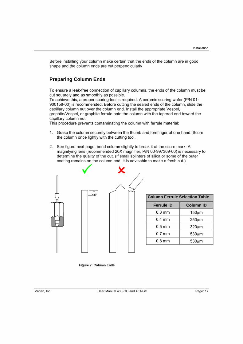
Before installing your column make certain that the ends of the column are in good shape and the column ends are cut perpendicularly
Preparing Column Ends
To ensure a leak-free connection of capillary columns, the ends of the column must be cut squarely and as smoothly as possible. To achieve this, a proper scoring tool is required. A ceramic scoring wafer (P/N 01-900158-00) is recommended. Before cutting the sealed ends of the column, slide the capillary column nut over the column end. Install the appropriate Vespel, graphite/Vespel, or graphite ferrule onto the column with the tapered end toward the capillary column nut. This procedure prevents contaminating the column with ferrule material: 1. Grasp the column securely between the thumb and forefinger of one hand. Score
the column once lightly with the cutting tool.
2. See figure next page, bend column slightly to break it at the score mark. A magnifying lens (recommended 20X magnifier, P/N 00-997369-00) is necessary to determine the quality of the cut. (If small splinters of silica or some of the outer coating remains on the column end, it is advisable to make a fresh cut.)
Figure 7: Column Ends
Column Ferrule Selection Table
Ferrule ID Column ID
0.3 mm 150μm
0.4 mm 250μm
0.5 mm 320μm
0.7 mm 530μm
0.8 mm 530μm

Installation
Page: 18 User Manual 430-GC and 431-GC Varian, Inc.
Ferrule Type Recommendation Comments
New graphite ferrule 1/4-turn past finger-tight 1/4- to 1/2-turn past finger-tight may be required to achieve a seal.
Used graphite ferrule 1/4-turn past finger-tight If a different size of column is used, more tightening may be required.
New polyimide/graphite ferrule
1/4- to 1/2-turn past finger-tight
May require retightening after first or second programmed run. Over tightening will destroy ferrule and seal.
Used polyimide/graphite ferrule
1/4-turn past finger-tight Re-use only on same size column.
New 100% polyimide ferrule
Not recommended with 1041 Injector
Used 100% polyimide ferrule
Not recommended with 1041 Injector
Table 1: General Tightening and Retightening for Common Ferrules

Installation
Varian, Inc. User Manual 430-GC and 431-GC Page: 19
CONNECTING GASES Connecting Gases
The only carrier gas allowed for the 430-GC is 99.999% pure helium or better.
Carrier gas supplied from cylinders or manifolds should have a two-stage regulator with 0 to 100 psi low-pressure stage. Set cylinder regulator pressure to 80 psi. Follow the steps below to connect gas supplies to your 430-GC.
1. Cut required lengths of heat-cleaned 1/8″ copper tubing for the carrier gas plumbing. Clean the ends of the tubing with a metal file.
2. Slide a 1/8″ Swagelok® nut, back ferrule, and front ferrule over one end of the
copper tubing and attach to the outlet fitting on the cylinder regulator.
3. Push the copper tubing into the outlet fitting as far as it will go, then pull back very slightly and tighten 3/4-turn past finger-tight with a 7/16″ wrench.
Figure 8: Proper Ferrule Orientation
4. Push the other end of the copper tubing into the filter base inlet fitting as far as it will go, then pull back very slightly and tighten 3/4-turn past finger-tight with a 7/16″ wrench.
5. Connect another length of copper tubing to the outlet of the filter base using a 1/8″ Swagelok® nut and back and front ferrules as above.
6. Push the copper tubing into the bulkhead fitting on the back of the 430-GC as far as it will go, then pull back very slightly and tighten 3/4-turn past finger-tight with a 7/16″ wrench.
7. Make sure the gas supply control valve, which controls gas pressure to the GC, is completely closed. Open this valve slowly and monitor the pressure gauges on the dual stage regulator. The first pressure gauge should now read the pressure of the cylinder.
1/8" Copper Tubing
Swagelok® Nut
Back Ferrule
Front Ferrule

Installation
Page: 20 User Manual 430-GC and 431-GC Varian, Inc.
8. Cautiously turn the regulator valve to supply gas to the GC. Watch the pressure gauge closely and adjust the pressure to 80 psi.
9. Install the carrier gas filter cartridge into the filter base following instructions provided in the Accessory Kit.
10. Leak check all fittings (see page 44).
11. Repeat this process as necessary for detector gases. However, use a secondary pressure of 60 psi for air and 40 psi for H2.
SETUP INFORMATION
Enter and enter essential parameters such as column diameter, length, and carrier gas.
ETHERNET COMMUNICATIONS
The 430-GC uses Ethernet as the means of external instrument control and to transfer digital data to a data system to which it is attached. When running with Ethernet, the 430-GC will have its IP Address assigned by either your company network, or by a connected Workstation. If you are using a workstation from another vendor that supports Varian GC products, refer to that vendor’s documentation to determine how it should be configured to work with Varian GCs. 430-GC may be connected in three basic configurations. If you have one 430-GC to connect directly to the Workstation PC and the Workstation PC is NOT connected to a company network, then you may connect using the Ethernet crossover cable supplied with the 430-GC.
Figure 9: 430-GC direct connected to the Workstation
Workstation
Ethernet Crossover Cablep/n 03-933511-01
430-GC
Installation
Varian, Inc. User Manual 430-GC and 431-GC Page: 21
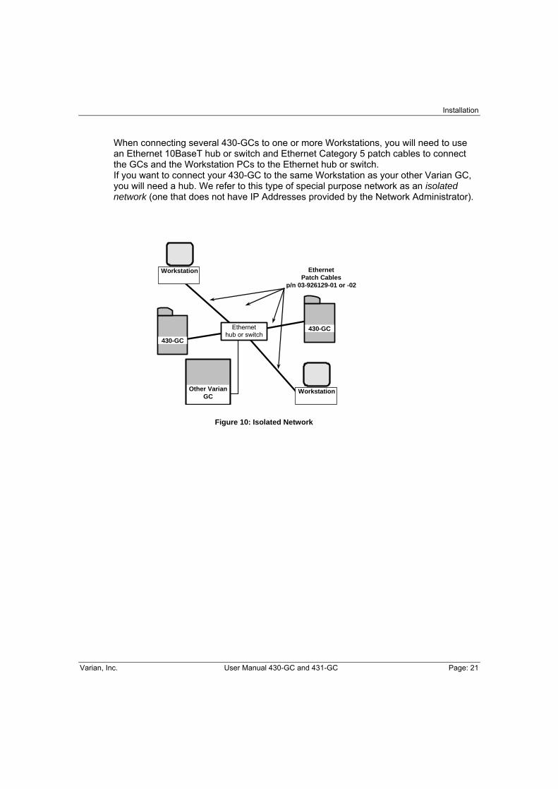
When connecting several 430-GCs to one or more Workstations, you will need to use an Ethernet 10BaseT hub or switch and Ethernet Category 5 patch cables to connect the GCs and the Workstation PCs to the Ethernet hub or switch. If you want to connect your 430-GC to the same Workstation as your other Varian GC, you will need a hub. We refer to this type of special purpose network as an isolated network (one that does not have IP Addresses provided by the Network Administrator).
Figure 10: Isolated Network
Ethernet Patch Cables
p/n 03-926129-01 or -02
Other Varian GC
Workstation
430-GC
430-GC
Workstation
Ethernet hub or switch
Installation
Page: 22 User Manual 430-GC and 431-GC Varian, Inc.
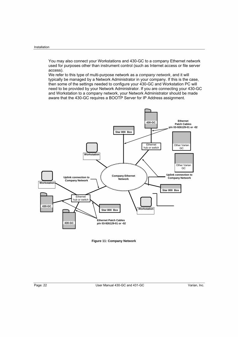
You may also connect your Workstations and 430-GC to a company Ethernet network used for purposes other than instrument control (such as Internet access or file server access). We refer to this type of multi-purpose network as a company network, and it will typically be managed by a Network Administrator in your company. If this is the case, then some of the settings needed to configure your 430-GC and Workstation PC will need to be provided by your Network Administrator. If you are connecting your 430-GC and Workstation to a company network, your Network Administrator should be made aware that the 430-GC requires a BOOTP Server for IP Address assignment.
Figure 11: Company Network
Other Varian GC
Workstation
Workstation
Workstation
Star 800 Box
Ethernet hub or switch
Ethernet Patch Cables p/n 03-926129-01 or -02
Star 800 Box
Ethernet Patch Cables
p/n 03-926129-01 or -02
Uplink connection to Company Network
Uplink connection to Company Network
Star 800 Box
Other Varian GC
430-GC
430-GC
Company Ethernet Network
430-GC
Ethernet hub or switch
Installation
Varian, Inc. User Manual 430-GC and 431-GC Page: 23
Network Terminology
If you are unfamiliar with network terminology, the following brief glossary of terms may be useful: BNC Connector This is a bayonet style connector used for a two conductor style hardware connection. BNC connectors are used with the CP-3800 GC. If you will be mixing 430-GCs and CP-3800 GCs within your lab you will want to make certain that you have hubs that support the 10Base2 (BNC) style connectors. BOOTP Server This is software that allows you to assign IP Addresses (and designate host names) to Ethernet devices such as the 430-GC, 450-GC, CP-3800 GC, 3900 GC, and Star 800 box that require static IP Address assignments. The Star Workstation has a BOOTP server built into it that may be accessed by clicking on Instrument menu and selecting Setup Ethernet Communications. Crossover Cable A cable that is only used to connect two Ethernet devices together. Domain This is one of several settings that reside within the TCP/IP configuration that identifies paths that are used to establish connections with Ethernet devices. The Domain is an IP Address. Ethernet Address This is a unique identifier that every Ethernet communication device has assigned to it. Typically, the Ethernet address can not be changed and is the permanent way of identifying a particular hardware device. The Ethernet address consists of 4 pairs of hexadecimal numbers. Gateway This is one of several settings within the TCP/IP configuration that identifies paths that are used to establish connections with Ethernet devices. The Gateway is assigned an IP Address. Host Name The host name is an alternate way of identifying a device that is friendlier to people. Frequently the host name and the IP Address may be used interchangeably (although both must be specified in the BOOTP server). Hub A device that allows many Ethernet devices to be interconnected. Several hubs may be interconnected (depending on the manufacturer) to increase the number of Ethernet connections. IP Address This is a unique number for each Ethernet device within the set of connected devices. Two PCs may have identical IP Addresses so long as they are not interconnected to each other either through a hub or through the internet. The IP Address consists of a series of four sets of decimal digits (between 1 and 3 characters typically) which encodes gateway and routing information that is used by the TCP/IP protocol to establish the most efficient and reliable connection. Without the IP Address, communications would be bogged down trying to establish connections to just the Ethernet address.

Installation
Page: 24 User Manual 430-GC and 431-GC Varian, Inc.
Patch Cable A cable that is used only to connect Ethernet devices to hubs or your company network. RJ45 Connector This is a telephone jack style connector used for a several conductor style hardware connection (10BaseT). RJ45-style connectors is used by the 430-GC. TCP/IP This particular Ethernet protocol supports the 430-GC, 3900 GC, CP-3800 GC, and the Star 800 box. You may find several network protocols supported by your PC. Overview The following steps are required to establish Ethernet communication with the 430-GC, and are described in the following sections:
1. Load the appropriate software onto your Workstation PC. 2. Set the network properties of your Workstation PC. 3. Connect cables. 4. Set up the BOOTP server to assign an IP Address to your 430-GC. 5. Configure your 430-GC into a Galaxie Workstation instrument.
Loading the Appropriate Software onto your Workstation PC Make sure that you have the necessary software installed on your Workstation PC. Follow the instructions that come with your upgrade/installation media to add 430-GC control to your Workstation.
Setting the Network Properties of your Workstation PC
If you will be connecting your Workstation PC to your company network, contact your Network Administrator to set your PC’s network properties in the TCP/IP section. If you will be connecting your Workstation PC directly to one or more GCs, with no connection to the company network, then set the following network properties on your PC:
Gateway 255.0.0.0
Domain 0.0.0.0
DNS Disabled
WNS Configuration Disabled Your Ethernet card will need to have an IP Address assigned to it. If your PC will not have any other Ethernet communications, there are no problems with IP Address conflicts, and you can set the IP Address to any value, for example 10.128.70.10.

Installation
Varian, Inc. User Manual 430-GC and 431-GC Page: 25
Connecting Cables
Power down both your PC and 430-GC.
The optional Ethernet connection is made at the back of the 430-GC (J10) on page 13. There are two types of cables (crossover and patch), which are used as shown in the figures in the introduction to this section.
If you will be connecting a single GC to a single Workstation PC, you should use the crossover cable to make the direct connection. Use the patch cable to connect the 430-GC to a hub or to your company network.
Installation
Page: 26 User Manual 430-GC and 431-GC Varian, Inc.
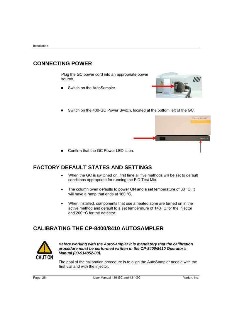
CONNECTING POWER Plug the GC power cord into an appropriate power source.
Switch on the AutoSampler.
Switch on the 430-GC Power Switch, located at the bottom left of the GC.
Confirm that the GC Power LED is on.
FACTORY DEFAULT STATES AND SETTINGS • When the GC is switched on, first time all five methods will be set to default
conditions appropriate for running the FID Test Mix.
• The column oven defaults to power ON and a set temperature of 80 °C. It will have a ramp that ends at 160 °C.
• When installed, components that use a heated zone are turned on in the active method and default to a set temperature of 140 °C for the injector and 200 °C for the detector.
CALIBRATING THE CP-8400/8410 AUTOSAMPLER
Before working with the AutoSampler it is mandatory that the calibration procedure must be performed written in the CP-8400/8410 Operator’s Manual (03-914852-00). The goal of the calibration procedure is to align the AutoSampler needle with the first vial and with the injector.

Installation
Varian, Inc. User Manual 430-GC and 431-GC Page: 27
INSTALLATION CONCLUSION The rest of this manual provides more detailed descriptions of how to set and use the various aspects of your GC. Please refer to the manual if some aspect of the instrument is not immediately clear or if you would like to understand more how this GC operates.
Keyboard and Display
Page: 28 User Manual 430-GC Varian, Inc.
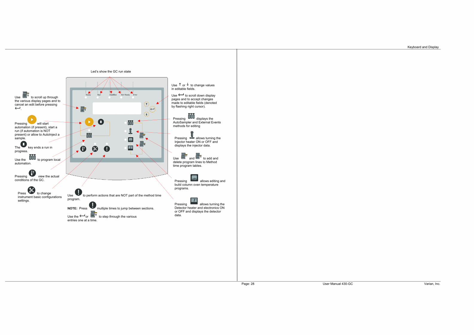
Led’s show the GC run state
Use or to change values in editable fields.
Use to scroll down display pages and to accept changes made to editable fields (denoted by flashing right cursor).
Use and to add and delete program lines to Method time program tables.
Pressing displays the AutoSampler and External Events methods for editing
Pressing allows turning the Injector heater ON or OFF and displays the injector data.
Pressing allows turning the Detector heater and electronics ON or OFF and displays the detector data.
Use to scroll up through the various display pages and to cancel an edit before pressing
.
Pressing will start automation (if present), start a run (if automation is NOT present) or allow to AutoInject a sample.
The key ends a run in progress.
Use the to program local automation.
Pressing view the actual conditions of the GC.
Press to change instrument basic configurations settings.
Use to perform actions that are NOT part of the method time program.
NOTE: Press multiple times to jump between sections.
Use the or to step through the various entries one at a time.
Pressing allows editing and build column oven temperature programs.
Display and Keyboard
Varian, Inc. User Manual 430-GC and 431-GC Page: 29
KEYPAD KEYS AND DISPLAY (The described software version in this section has revision 6.93)
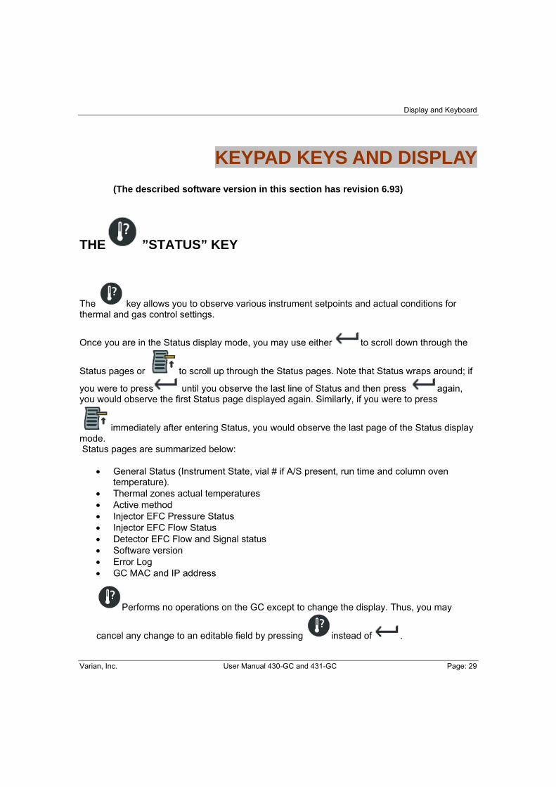
THE ”STATUS” KEY
The key allows you to observe various instrument setpoints and actual conditions for thermal and gas control settings.
Once you are in the Status display mode, you may use either to scroll down through the
Status pages or to scroll up through the Status pages. Note that Status wraps around; if
you were to press until you observe the last line of Status and then press again, you would observe the first Status page displayed again. Similarly, if you were to press
immediately after entering Status, you would observe the last page of the Status display mode. Status pages are summarized below:
• General Status (Instrument State, vial # if A/S present, run time and column oven temperature).
• Thermal zones actual temperatures • Active method • Injector EFC Pressure Status • Injector EFC Flow Status • Detector EFC Flow and Signal status • Software version • Error Log • GC MAC and IP address
Performs no operations on the GC except to change the display. Thus, you may
cancel any change to an editable field by pressing instead of .

Keyboard and Display
Page: 30 User Manual 430-GC and 431-GC Varian, Inc.
THE ”UP LINE” KEY
simply moves the display to the immediate preceding page for viewing. It does not operate on any function of the GC other than the currently displayed page. If the display is already at the
top of a section, then pressing will take you to the last line of the section.
THE “START” KEY
The key operates on your 430-GC in one of two ways:
If NO CP-8400 or a CP-8410 is present, pressing will cause the 430-GC to execute the currently active method. The run time will begin incrementing and any time programs will be executed.
If a CP-8400 or a CP-8410 is present, pressing will allow you to either perform an AutoInjection or start the currently active method. The default action is to perform an AutoInjection. Upon accepting the AutoInjection selection you will be prompted for the sample vial, the sample volume and the number of replicate
injections you wish to perform. You may cancel an AutoInjection by pressing the or keys.
Once a run is started you may either allow the run to complete or press the key to terminate it.

Display and Keyboard
Varian, Inc. User Manual 430-GC and 431-GC Page: 31
THE ”STOP” KEY
The key is to terminate an executing method and cycle back to initial conditions. The key is also used to interrupt Local Automation.
THE ”ENTER” KEY The key performs two functions:
1. If an editable field has been changed, the key will accept and execute that change.
2. If no changes have been made, then the key will advance to the next line on the display.
If you edit a field, you will press to accept the edited value and advance to the next line of the display. Note that once you change the entry for a field a flashing underscore cursor will be displayed showing that the field is being edited. If the underscore cursor is
flashing and you do not want to accept the changed field, you may press the key located at the left side of the display to discard any edits that may have been made to that field. If you press , the edits will be accepted.
Keyboard and Display
Page: 32 User Manual 430-GC and 431-GC Varian, Inc.
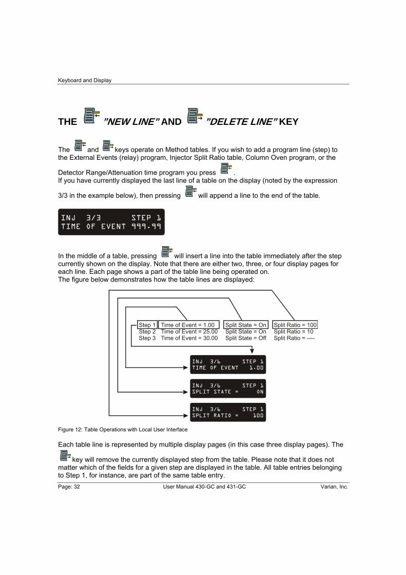
THE ”NEW LINE” AND ”DELETE LINE” KEY
The and keys operate on Method tables. If you wish to add a program line (step) to the External Events (relay) program, Injector Split Ratio table, Column Oven program, or the
Detector Range/Attenuation time program you press . If you have currently displayed the last line of a table on the display (noted by the expression
3/3 in the example below), then pressing will append a line to the end of the table.
In the middle of a table, pressing will insert a line into the table immediately after the step currently shown on the display. Note that there are either two, three, or four display pages for each line. Each page shows a part of the table line being operated on. The figure below demonstrates how the table lines are displayed: Figure 12: Table Operations with Local User Interface Each table line is represented by multiple display pages (in this case three display pages). The
key will remove the currently displayed step from the table. Please note that it does not matter which of the fields for a given step are displayed in the table. All table entries belonging to Step 1, for instance, are part of the same table entry.

Display and Keyboard
Varian, Inc. User Manual 430-GC and 431-GC Page: 33
THE ”SETUP” KEY
The parameters available from the key are summarized in the Setup Outline below (if NO CP-8400 or CP-8410 is installed you will not see the AutoSampler Setup section): Language English
French Spanish Italian German Japanese (Katakana)
EFC (type 1 for 1177 Injector) Gas Type He, N2, H2
Outlet Atm, Vacuum Units psi, kPa, Barr Gas Saver Timeout 0 (off) to 999.99 min (If the GC is idle for the set period of time, the Gas Saver flow rate is implemented and an advisory Error is created. Activate a Method to clear the Error.) Gas Saver Flowrate 0 to 100 mL/min Splitless Vent Flow 0 to 100 mL/min Septum Purge Calibrate
EFC (type 4 for 1041 injector) Gas Type He, N2, H2
Outlet Atm, Vacuum Units psi, kPa, Barr Gas Saver Timeout 0 (off) to 999.99 min (If the GC is idle for the set period of time, the Gas Saver flow rate is implemented and an advisory Error is spawned. Activate a Method to clear the Error.) Gas Saver Flowrate 0 to 100 mL/min Splitless Vent Flow 0 to 100 mL/min

Keyboard and Display
Page: 34 User Manual 430-GC and 431-GC Varian, Inc.
Column Length 0.01 to 200.00m
I.D. 20 to 530 μm, packed Standby Temperature 50 to 450 ºC Standby Time-out 0.00 (off) to 999.99 min
Temperature Limits Column Temperature zone upper limit (50 to 450 ºC)
Detector Temperature zone upper limit (50 to 450 ºC) Injector Temperature zone upper limit (50 to 450 ºC)
AutoSampler Calibrate Vial 0/1
Injector Syringe Volume 5, 10, 100, 250 μL
Date/Time Date MM/DD/YY DD/MM/YY Time
Password Set keypad Password Locked/Unlocked Enter Password ********

Display and Keyboard
Varian, Inc. User Manual 430-GC and 431-GC Page: 35
THE ”COMMAND” KEY
The key gives you access to a variety of operations that are not properly associated with either method program execution or the GC configuration. Method Actions Activate Method Methods 1, 2, 3, 4, or 5
Copy Method Methods 1, 2, 3, 4, 5 to 1, 2, 3, 4, 5 Set Method to Defaults Methods 1, 2, 3, 4, or 5
AutoSampler Actions Change Syringe Beeper On/Off Move Tower Home Reset Plunger Stroke Counter Plunger Stroke # Warning Limit Syringe Penetration Speed into Injector Syringe Depth into Injector
Detector Actions AutoZero Now! Clear AutoZero! Ignite Flame Now! (FID only)
Remote Control Enable/Disable a remote Workstation

Keyboard and Display
Page: 36 User Manual 430-GC and 431-GC Varian, Inc.
The following sections outline the parameters that are available under each method icon.
THE ”AUTO” KEY This key will give access to the AutoSampler and External Events Method section. The following section lists the parameters for the CP-8400 AutoSampler and CP-8410 AutoInjector. If no AutoSampler is connected the parameters will not be displayed. Your AutoSampler/ AutoInjector manual will describe each of these parameters in detail. Autosampler
AutoSampler Mode Standard Split/Splitless, Volatile, Viscous, Neat, Standard OC, User
Sample Penetration Depth Default = 90% (0 to 100%) Solvent Penetration Depth Default = 90% (0 to 100%) # of Pre-Injection Solvent Clean Flushes Default = 3 (0 to 99) # of Post-Injection Solvent Clean Flushes Default = 1 (0 to 99) # of Pre-Injection Sample Clean Flushes Default = 0 (0 to 99)
Clean Solvent Source Vial Default =1 (1, 2, 3, 1&2, 1&3, 2&3, 1&2&3)
Default Clean Vial Default =1 (1, 2, 3) Default Clean Volume (µL) Default =5 (0 to 5 or 10 or 100) Default Clean Drawup Speed Default =5 (0 to 25 or 50) Number of Default Clean Strokes Default =1 (1 to 10) Air Plug After Sample (µL) Default =1 (0 to 5 or 10) Sample Air Gap? Default =No ( Yes or No) Number of Fill Strokes Default =0 (0 to 99) Fill volume for Fill Strokes (µL) Default =5 (0 to 5 or 10 or 100) Viscosity Delay (sec) Default =0 (0 to 99.9) Plunger Speed during Fill (µL/sec) Default =5 (0.1 to 25 or 50) Plunger Speed during Injection (µL/sec) Default =50 (0.1 to 25 or 50) Pre-Injection Delay (sec) Default =0 (0 to 99.9) Post-Injection Delay (sec) Default =0 (0 to 99.9) Use Internal Standard? Default =No (Yes/No) Internal Standard Vial Default =2 (1,2,3) Internal Standard Size (µL) Default =1 (0 to 4.9 or 0 to 9.0) Internal Standard Drawup Speed (µL/sec) Default =5 (0.1 to 25 or 50) Internal Standard Pause Time (sec) Default =0 (0 to 9.9) Internal Standard Air Gap? Default = Yes (Yes/No) Vial for Solvent Plug Default =1 (1,2,3) Solvent Plug Size (µL) Default =0 (0 to 5 or 10) Solvent Drawup Speed (µL/sec) Default =5 (0.1 to 25 or 50) Solvent Pause Time (sec) Default =0 (0 to 9.9) Solvent Air Gap Default = No (Yes/No)

Display and Keyboard
Varian, Inc. User Manual 430-GC and 431-GC Page: 37
External Events Initial 1 On/Off 2 On/Off Default =Off 0.01 ... 999.99 1 On/Off 2 On/Off Default =Off
. .
External Events are 24 Vac, 200 mA max current.
. . . . 0.01 ... 999.99 1 On/Off 2 On/Off Default =Off
You may add lines to the External Events program by pressing the key. You may delete a
line by scrolling so that the desired line is displayed and then pressing the key. If your 430-GC is equipped with a sampling valve, you will use the external events to operate/toggle the valve’s position. Note that the initial state of the valve will depend on whether the external event’s initial state is energized (on) or de-energized (off).
THE ”INJECTOR ” KEY This key will give access to the Injector and Pressure/Flow settings 1177 Injector.
Injector Outline
Injector Oven On/Off Injector Temp. 50 to 450 ºC
Mode Isobaric/Constant Flow Default = Isobaric
Pressure 0.1 to 100.0 psi Default =10.0 Pressure Pulse? Yes/No Default =No Pressure Pulse Pressure 0.1 to 100.0 psi Default =10.0 Pressure Pulse Duration 0.01 to 10.00 min Default =0.25 Initial Split Ratio On/Off Split ratio (1 to 10,000) Time On/Off Split ratio (1 to 10,000) Time On/Off Split ratio (1 to 10,000) Time On/Off Split ratio (1 to 10,000) Time On/Off Split ratio (1 to 10,000)
You may add lines to the Injector Split Ratio program by pressing the key. You may delete
a line by scrolling so that the desired line is displayed and then pressing the key.
Keyboard and Display
Page: 38 User Manual 430-GC and 431-GC Varian, Inc.
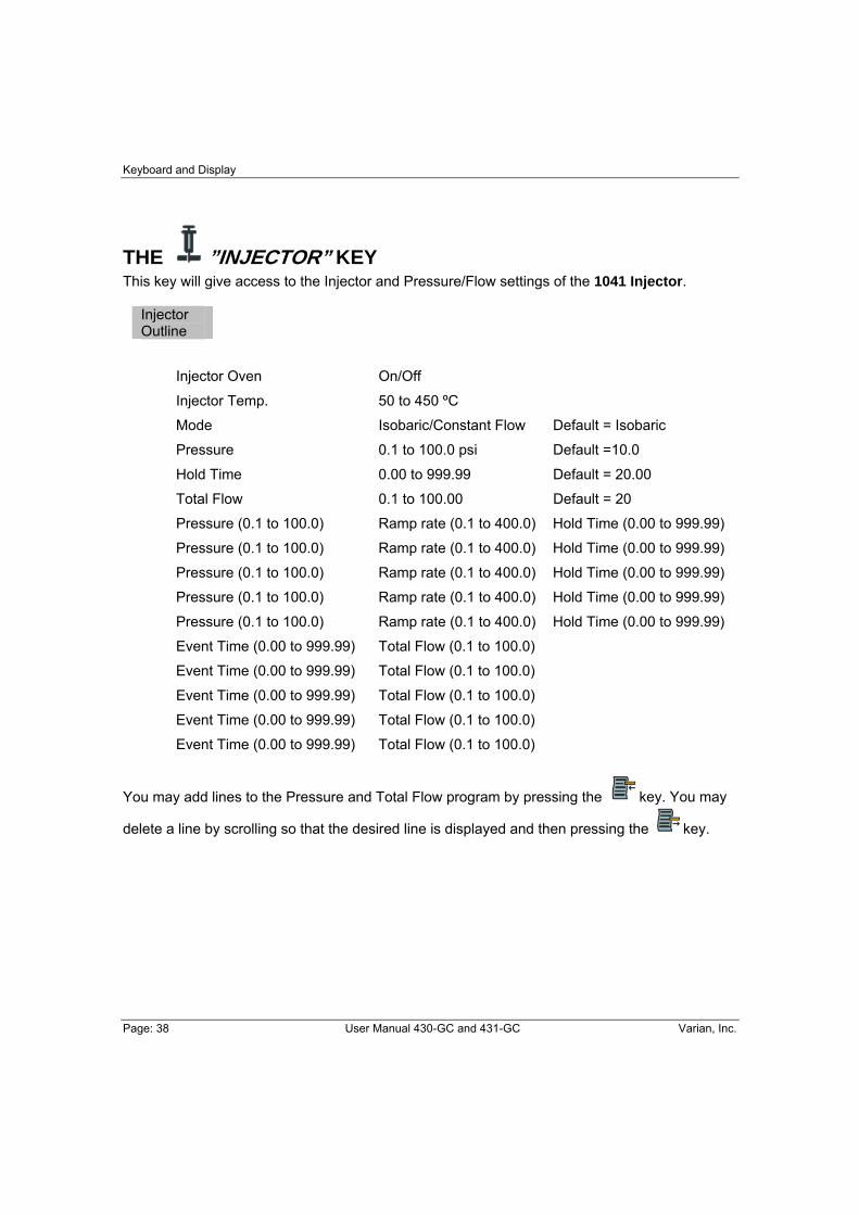
THE ”INJECTOR” KEY This key will give access to the Injector and Pressure/Flow settings of the 1041 Injector.
Injector Outline
Injector Oven On/Off
Injector Temp. 50 to 450 ºC
Mode Isobaric/Constant Flow Default = Isobaric
Pressure 0.1 to 100.0 psi Default =10.0
Hold Time 0.00 to 999.99 Default = 20.00
Total Flow 0.1 to 100.00 Default = 20
Pressure (0.1 to 100.0) Ramp rate (0.1 to 400.0) Hold Time (0.00 to 999.99)
Pressure (0.1 to 100.0) Ramp rate (0.1 to 400.0) Hold Time (0.00 to 999.99)
Pressure (0.1 to 100.0) Ramp rate (0.1 to 400.0) Hold Time (0.00 to 999.99)
Pressure (0.1 to 100.0) Ramp rate (0.1 to 400.0) Hold Time (0.00 to 999.99)
Pressure (0.1 to 100.0) Ramp rate (0.1 to 400.0) Hold Time (0.00 to 999.99)
Event Time (0.00 to 999.99) Total Flow (0.1 to 100.0)
Event Time (0.00 to 999.99) Total Flow (0.1 to 100.0)
Event Time (0.00 to 999.99) Total Flow (0.1 to 100.0)
Event Time (0.00 to 999.99) Total Flow (0.1 to 100.0)
Event Time (0.00 to 999.99) Total Flow (0.1 to 100.0)
You may add lines to the Pressure and Total Flow program by pressing the key. You may
delete a line by scrolling so that the desired line is displayed and then pressing the key.

Display and Keyboard
Varian, Inc. User Manual 430-GC and 431-GC Page: 39
THE ”OVEN” KEY This key will give access to the Oven settings.
Oven Outline
Stabilize Time 0.0 to 10.0 minutes
Initial Temp. 30 to 450 ºC ----- Hold (0 to 999.99 min)
Ramp End Temp 30 to 450 ºC Rate Hold (0 to 999.99 min)
Ramp End Temp 30 to 450 ºC Rate Hold (0 to 999.99 min)
Ramp End Temp 30 to 450 ºC Rate Hold (0 to 999.99 min)
Ramp End Temp 30 to 450 ºC Rate Hold (0 to 999.99 min)
Ramp End Temp 30 to 450 ºC Rate Hold (0 to 999.99 min)
Ramp End Temp 30 to 450 ºC Rate Hold (0 to 999.99 min)
Ramp End Temp 30 to 450 ºC Rate Hold (0 to 999.99 min)
Column Coolant Enable/Disable Enabled or Disabled
Coolant Threshold Temperature 50 to 250 ºC
You may add lines to the Column Oven program by pressing the key. You may delete a
line by scrolling so that the desired line is displayed and then pressing the key.

Keyboard and Display
Page: 40 User Manual 430-GC and 431-GC Varian, Inc.
THE ”DETECTOR” KEY This key will give access to the Detector Flow settings FID.
Detector
Oven On/Off
Temperature 50 to 450 ºC
Electronics On/Off
Range (9, 10, 11, 12)
AutoZero Yes/No
Time Constant Slow (Fast/Slow)
Attenuation (1 to 1024)
Initial Range Attenuation A/Z
Time Range Attenuation A/Z
Time Range Attenuation A/Z
Time Range Attenuation A/Z
Time Range Attenuation A/Z
H2 Flow 0.00 to 50.00
Air Flow 0.00 to 500.0
Makeup Flow 0.00 to 50.00
You may add lines to the Detector Attenuation program by pressing the key. You may
delete a line by scrolling so that the desired line is displayed and then pressing the key.
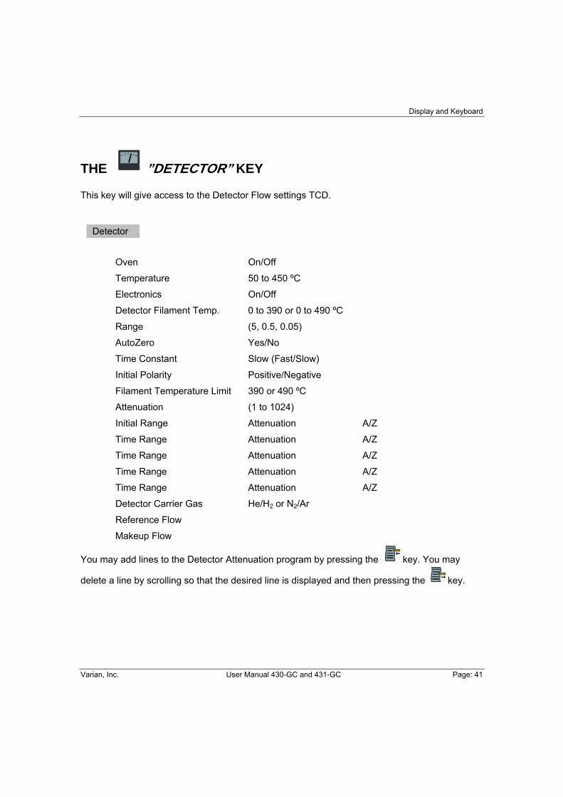
Display and Keyboard
Varian, Inc. User Manual 430-GC and 431-GC Page: 41
THE ”DETECTOR” KEY This key will give access to the Detector Flow settings TCD.
Detector
Oven On/Off
Temperature 50 to 450 ºC
Electronics On/Off
Detector Filament Temp. 0 to 390 or 0 to 490 ºC
Range (5, 0.5, 0.05)
AutoZero Yes/No
Time Constant Slow (Fast/Slow)
Initial Polarity Positive/Negative
Filament Temperature Limit 390 or 490 ºC
Attenuation (1 to 1024)
Initial Range Attenuation A/Z
Time Range Attenuation A/Z
Time Range Attenuation A/Z
Time Range Attenuation A/Z
Time Range Attenuation A/Z
Detector Carrier Gas He/H2 or N2/Ar
Reference Flow
Makeup Flow
You may add lines to the Detector Attenuation program by pressing the key. You may
delete a line by scrolling so that the desired line is displayed and then pressing the key.

Keyboard and Display
Page: 42 User Manual 430-GC and 431-GC Varian, Inc.
THE ”AUTO” KEY The Automation Schedule is not a method section. This section is only available if a CP-8400 or CP-8410 is connected to the 430-GC.
The parameters under this icon modify the behavior of the key and it is for this reason it is
grouped.
The key is where you schedule what vials your CP-8400 or CP-8410 will inject and with which method. This is different from the Automation Method Section where the actual
AutoSampler parameters are entered. This icon is grouped with the STOP
and START keys since once the schedule of samples is entered, will cause the Automation
to begin and will stop automation. You will know when the Automation Schedule is set to Single Method and is thus active by the LED located immediately above the Automation Schedule icon. If that LED is illuminated then
pressing will begin Automation. If the LED is not illuminated then the 430-GC is in manual mode.
Automation Outline
Automation Mode Manual, Single Method Automation Method Automation Starting Vial Automation End Vial Number of Injections/Vial
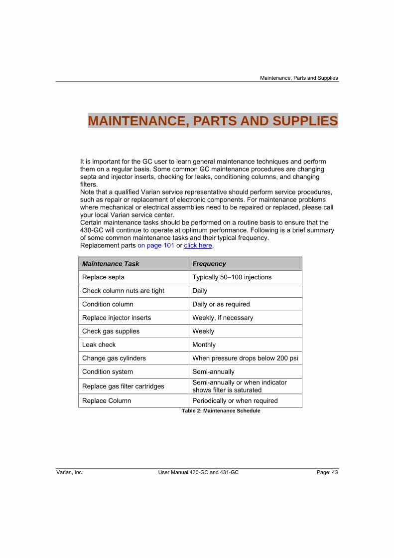
Maintenance, Parts and Supplies
Varian, Inc. User Manual 430-GC and 431-GC Page: 43
MAINTENANCE, PARTS AND SUPPLIES
It is important for the GC user to learn general maintenance techniques and perform them on a regular basis. Some common GC maintenance procedures are changing septa and injector inserts, checking for leaks, conditioning columns, and changing filters. Note that a qualified Varian service representative should perform service procedures, such as repair or replacement of electronic components. For maintenance problems where mechanical or electrical assemblies need to be repaired or replaced, please call your local Varian service center. Certain maintenance tasks should be performed on a routine basis to ensure that the 430-GC will continue to operate at optimum performance. Following is a brief summary of some common maintenance tasks and their typical frequency. Replacement parts on page 101 or click here. Maintenance Task Frequency
Replace septa Typically 50–100 injections
Check column nuts are tight Daily
Condition column Daily or as required
Replace injector inserts Weekly, if necessary
Check gas supplies Weekly
Leak check Monthly
Change gas cylinders When pressure drops below 200 psi
Condition system Semi-annually
Replace gas filter cartridges Semi-annually or when indicator shows filter is saturated
Replace Column Periodically or when required Table 2: Maintenance Schedule

Maintenance, Parts and Supplies
Page: 44 User Manual 430-GC and 431-GC Varian, Inc.
GENERAL GC MAINTENANCE The most common GC maintenance tasks are checking and changing gas supply cylinders, leak checking, and changing gas filter cartridges. These tasks should be performed at the frequency suggested in the above table. The following procedures are critical to the successful long-term operation of a 430-GC. It is very important to leak check the system on a routine basis and to ensure the quality of gas supplies.
Checking and Renewing Gas Supplies
The pressure of the various GC gas supplies should be checked on a weekly basis and the following guidelines used for frequency of renewing supplies. The carrier gas supply cylinder should be changed when its pressure drops below 200 psi. This ensures that high purity carrier gas is always supplied to the instrument. With typical usage on one gas chromatograph, a cylinder of carrier gas should last for three to six months. When a new cylinder is installed, the regulator and tubing should be purged with carrier gas before connecting to the GC. This will avoid introducing a large amount of air into the GC.
Leak Checking Leak checking is one of the most important maintenance tasks performed on a GC. Leaks in the GC system may lead to poor chromatographic performance or may damage components such as the analytical column. The presence of oxygen in the GC carrier gas at elevated temperatures can lead to permanent column phase degradation. While the use of an oxygen filter on the carrier supply to the instrument can help, leaks downstream of the filter are generally more likely to be the problem.
The use of soap-based leak detection fluids is not recommended for a high performance capillary Gas Chromatograph due to the danger of introducing contaminants into the system.
The most important step in leak checking is to verify that the GC system can hold pressure. This is done by removing the column from the injector, sealing all exits from the injector and pressurizing the system.
Maintenance, Parts and Supplies
Varian, Inc. User Manual 430-GC and 431-GC Page: 45
Use the following procedure to leak check the 430-GC.
Required Materials
No-hole ferrule Unused septum Column fitting Crescent wrench Supply valve Leak detector
When conducting leak check procedures it is important to completely seal all carrier gas exits, including septum purge and split vent outlets.
The injector nut may be hot. Lower the injector temperature to 50 °C and permit the injector nut to cool before proceeding.
1. Remove injector septum nut and install a new septum. An older septum can often be the source of a substantial leak.
2. Remove the column from the injector. Use the appropriate nut and ferrule to seal
the base of the injector. For capillary systems use a capillary nut (03-949551-00) with a no-hole ferrule (28-694590-01).
3. The septum purge and split vent outlets must be sealed. The septum purge outlet is
located on the top frame surrounding the column oven, behind the cap above the column oven door. The split vent outlet is located on the left side panel of the 430-GC. Seal the septum purge by removing the fitting from the septum purge valve and replacing it with a blank off plug (28-247071-01). You may set the Splitless Vent Flow in the 430-GC configuration to a flow of 0 and set the split ratio to off.
4. With all outlet ports plugged, pressurize the system to 80 psi. Setting the isobaric
pressure to 80 psi either at the 430-GC Keypad or via downloaded Workstation Method.
5. Shut off the carrier supply at the source and monitor the displayed pressure at the
GC for five minutes. The pressure should not drop more than 4 psi in five minutes.
Leak checking ensures that there are no leaks in the GC system up to and including the injector assembly. If the indicated pressure on the GC drops by more than 4 psi during the five minute test period, this indicates that there is a leak in the system. Finding such a leak, particularly if it is a small leak, can be very difficult. In general, the best approach is to systematically go through the pneumatic system from the source and tighten each fitting until the leak is eliminated. It is important to note that leaks are most often found in the carrier gas supply to the GC.
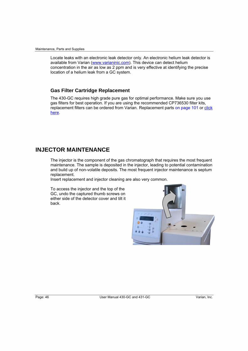
Maintenance, Parts and Supplies
Page: 46 User Manual 430-GC and 431-GC Varian, Inc.
Locate leaks with an electronic leak detector only. An electronic helium leak detector is available from Varian (www.varianinic.com). This device can detect helium concentration in the air as low as 2 ppm and is very effective at identifying the precise location of a helium leak from a GC system.
Gas Filter Cartridge Replacement The 430-GC requires high grade pure gas for optimal performance. Make sure you use gas filters for best operation. If you are using the recommended CP736530 filter kits, replacement filters can be ordered from Varian. Replacement parts on page 101 or click here.
INJECTOR MAINTENANCE
The injector is the component of the gas chromatograph that requires the most frequent maintenance. The sample is deposited in the injector, leading to potential contamination and build up of non-volatile deposits. The most frequent injector maintenance is septum replacement. Insert replacement and injector cleaning are also very common. To access the injector and the top of the GC, undo the captured thumb screws on either side of the detector cover and tilt it back.
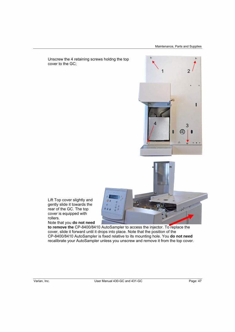
Maintenance, Parts and Supplies
Varian, Inc. User Manual 430-GC and 431-GC Page: 47
Unscrew the 4 retaining screws holdng the top cover to the GC; Lift Top cover slightly and gently slide it towards the rear of the GC. The top cover is equipped with rollers. Note that you do not need to remove the CP-8400/8410 AutoSampler to access the injector. To replace the cover, slide it forward until it drops into place. Note that the position of the CP-8400/8410 AutoSampler is fixed relative to its mounting hole. You do not need recalibrate your AutoSampler unless you unscrew and remove it from the top cover.
1 2
3 4

Maintenance, Parts and Supplies
Page: 48 User Manual 430-GC and 431-GC Varian, Inc.
Septum Replacement The injector septum is an expendable part and must be replaced on a routine basis. The frequency of replacement depends on the number of injections and whether the injections are by hand or with an autosampler. In general the septum should be replaced every 50–100 injections or when symptoms of a septum leak are seen (septum peaks in chromatogram). These symptoms include changing retention times, reduced detector response, or a drop in column head pressure.
The injector nut may be hot. Lower the injector temperature to 50 °C and permit the injector nut to cool before proceeding.
1. Turn off the carrier gas supply to the injector.
2. Remove the injector nut by turning it counterclockwise.
3. Remove the old septum using metal tweezers or a septum pick (72-000084-00). Do not
handle any internal parts of the injector with hands or gloves (Lint-free).
4. Install the new septum, again using tweezers to avoid contaminating the injector.
5. Replace the injector nut and tighten it finger-tight until you feel resistance from the septum, then tighten an extra 1/4 turn. Turn on the carrier gas supply (monitor carrier pressure when power up).
On occasion to save time you may want to change a septum while the injector is hot. Use an injector wrench (03-908423-00) to remove and reinstall the injector nut. In all instances the column oven should be cool before removing the injector nut to minimize damage to the column caused by air entering the injector when the septum is removed.

Maintenance, Parts and Supplies
Varian, Inc. User Manual 430-GC and 431-GC Page: 49
Insert Replacement The 1177 is a Split/Splitless capillary injector. Typically, to change from Split operation to Splitless may involve changing the injector insert. The insert should also be cleaned or replaced on a routine basis. This is especially important when dirty samples are being analyzed.
Removing the Glass Insert
Follow these steps to remove the glass insert from the 1177 Injector.
The injector nut may be hot. Lower the injector temperature to 50 °C and permit the injector nut to cool before proceeding.
1. Use the injector nut wrench to remove the injector nut. Place the nut on a clean surface (e.g., clean tissue).
2. With tweezers or septum pick, lift the edge of the septum. Remove the septum.
Note: Replace the injector septum each time the glass insert is replaced.
3. Remove the start switch by unscrewing the retaining nut.
4. Unscrew the two captive screws holding the septum purge head to the base.
Carefully move this assembly straight up until it clears the top of the insert.
5. Use a laboratory tissue or clean tweezers to grasp the glass insert and remove it from the injector body.
Use care when removing inserts from the injector. Inserts can be at high temperatures and are likely hot. Place hot inserts on a clean glass or metal surface only.
6. To remove the O-ring from the glass insert, use clean lab tissues to hold the O-ring and the glass insert. Gently turn the glass insert while you pull off the O-ring.
Note: The glass inserts can be cleaned and reused. We recommend that you use a new O-ring each time you remove the insert for cleaning or replacement.
Maintenance, Parts and Supplies
Page: 50 User Manual 430-GC and 431-GC Varian, Inc.
Inserting the Glass Insert
Follow these steps to replace the glass insert in the 1177 Injector.
1. Using tweezers or clean lab tissue carefully slide the new insert into the injector body. Place a new o-ring over the insert and gently work it down until it sits over the o-ring seat at the top of the injector body. Use tweezers to work the o-ring down the insert. Avoid touching either the o-ring or the insert.
2. Carefully place the septum purge head over the insert. Tighten the two captive screws alternately for uniform seating of the purge head onto the body and uniform seal of the o-ring. Note that placing the purge head onto the body may take some care since the gas supply line and septum purge lines may have minor resistance to movement.
3. Reinstall the injector switch and retaining nut.
4. Use tweezers to place a new septum in the purge head.
Note: If the septum has a Teflon® face, place the Teflon face down toward the column.
5. Place the injector nut on the injector and tighten by hand until you feel some resistance, then tighten an extra 1/4-turn using the injector nut wrench.
Note: After the injector nut has been replaced, check the split vent and septum purge flow rates to ensure these values have not changed.
6. Condition the insert by setting the 1177 Injector to the split mode and purging with carrier gas for 30 minutes at 300 °C.
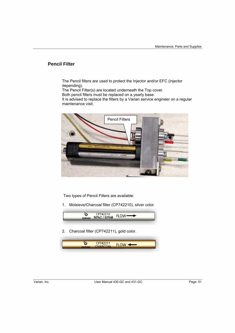
Maintenance, Parts and Supplies
Varian, Inc. User Manual 430-GC and 431-GC Page: 51
Pencil Filter
The Pencil filters are used to protect the Injector and/or EFC (injector depending). The Pencil Filter(s) are located underneath the Top cover. Both pencil filters must be replaced on a yearly base. It is advised to replace the filters by a Varian service engineer on a regular maintenance visit. Two types of Pencil Filters are available: 1. Molsieve/Charcoal filter (CP742210), silver color.
2. Charcoal filter (CP742211), gold color.
Pencil Filters

Maintenance, Parts and Supplies
Page: 52 User Manual 430-GC and 431-GC Varian, Inc.
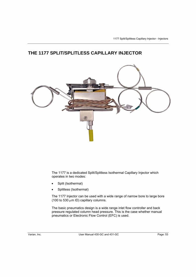
1177 Split/Splitless Capillary Injector - Injectors
Varian, Inc. User Manual 430-GC and 431-GC Page: 53
THE 1177 SPLIT/SPLITLESS CAPILLARY INJECTOR
The 1177 is a dedicated Split/Splitless Isothermal Capillary Injector which operates in two modes:
• Split (Isothermal)
• Splitless (Isothermal)
The 1177 Injector can be used with a wide range of narrow bore to large bore (100 to 530 μm ID) capillary columns.
The basic pneumatics design is a wide range inlet flow controller and back pressure regulated column head pressure. This is the case whether manual pneumatics or Electronic Flow Control (EFC) is used.
Injectors – 1177 Split/Splitless Capillary Injector
Page: 54 User Manual 430-GC and 431-GC Varian, Inc.
Features of the 1177 injector
• The 1177 operates isothermally from 50 to 450 °C.
• Changing from one injection mode to another typically involves a change of injector insert and a modification to the injector and EFC program. Glass inserts can be easily changed from the top of the injector.
• The internal injector temperature profile keeps the septum cool while maintaining the point of injection at the setpoint temperature.
• The 1177 uses positive septum purge to minimize the adsorption of sample onto the injector septum and to prevent contaminants from the septum entering the column.
• The 1177 uses a unique dual split vent that allows effective sweeping of the entire injector body.
Automatic Start Switch
The automatic start switch is a spring loaded actuator that fits over, and is aligned with, the injection port of the 1177 injector nut. The GC run is started when the actuator is depressed by the syringe barrel, or manually pressed at the moment of sample injection. The GC run can also be manually started by
pressing the START key on the keyboard.
The injector nut and automatic start switch assembly may be very hot during instrument operation and should not be touched with unprotected hands.
1177 Injector Inserts
Click here to see the 1177 Injector Inserts, on page 103. Note that all 1177 injector inserts are deactivated for maximum inertness.
1177 Split/Splitless Capillary Injector - Injectors
Varian, Inc. User Manual 430-GC and 431-GC Page: 55
1177 Modes of Injection
The 1177 injection mode is defined by the Split Vent program and by the choice of insert. The Split Vent is controlled differently based on the pneumatics installed, if EFC the split valve is controlled from the Injector section, or if manual pneumatics the external events control the split valve. The following are brief descriptions of the various modes of injection. More detailed information on each mode is given later in this section.
Split Mode
The split injection mode is preferred for the analysis of relatively concentrated samples. The sample is split in the injector with a representative portion entering the column. The split injection mode provides the shortest sampling time which leads to sharp chromatographic peaks. Use the 4.0 mm open insert, or the packed 4.0 mm ID insert when operating in the split mode.
In the split injection mode, the sample volume is typically 2 μL or less. Early eluting compounds usually appear as very sharp peaks. In some cases, the peak width is less than one second. It is important that you inject the sample as quickly as possible. If you are using the CP-8400 AutoSampler use the Standard Split/Splitless mode of injection. If you are using a non-Varian AutoSampler or you are using the User Defined Mode of operation on the CP-8400 AutoSamplers, if the sample injection time (the time between the insertion and removal of the syringe needle from the injector) exceeds the peak width, peaks can broaden, tail or chromatographic performance will be degraded. With broader, later eluting peaks, it is less important that you inject the sample quickly. The split ratio (fraction of sample that enters the column) is the ratio of the flow of carrier gas out the split vent to the flow through the column.
Splitless Mode
The 4 mm insert packed with glass wool is typically used for isothermal splitless injection. The small capillary section of the glass insert fits around the syringe needle and restricts backflash of the sample vapor during injection. In the splitless injection mode, the sample enters the column during a variable sampling time at the beginning of the analysis. This period is typically 30-90 seconds during which there is no flow from the injector to the split vent. After the sampling time, the injector is vented to remove any residual solvent and sample out of the injector.

Injectors – 1177 Split/Splitless Capillary Injector
Page: 56 User Manual 430-GC and 431-GC Varian, Inc.
1177 Electronic Flow Control (EFC) The EFC module used on an 1177 injector is the EFC21 or EFC25. The EFC21 or EFC25 type is designed specifically for the 1177 and 1079 PTV injectors to support their various modes of operation. It duplicates the behavior of the Split/Splitless manual pneumatics system in that there is an inlet mass flow controller supplying carrier gas to the injector and a pressure control valve downstream from the injector which sets the injector pressure. As injector pressure determines the rate of carrier gas flow through the column, this pressure is monitored close to the point of injection. Type EFC21 allows the user to set constant injector pressure or constant flow. In addition the split ratio can be programmed.
Figure 13: EFC21 and 1177 in Split mode Flow Diagram
* See Pencil Filters on page 51
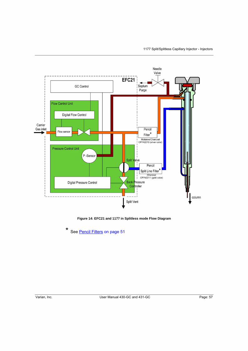
1177 Split/Splitless Capillary Injector - Injectors
Varian, Inc. User Manual 430-GC and 431-GC Page: 57
Figure 14: EFC21 and 1177 in Splitless mode Flow Diagram
* See Pencil Filters on page 51

Injectors – 1177 Split/Splitless Capillary Injector
Page: 58 User Manual 430-GC and 431-GC Varian, Inc.
The EFC25 is almost identical as the EFC21 the only exception is that the pressure is monitored at the module itself rather than at the Injector. This allows the EFC25 to be used with Gas or Liquid Sample Valve’s and Purge and Trap devices upstream from the Injector.
Figure 15: EFC25 Flow Diagram
* See Pencil Filters on page 51
1177 Split/Splitless Capillary Injector - Injectors
Varian, Inc. User Manual 430-GC and 431-GC Page: 59
1177 Manual Pneumatics
The total flow into the system is adjusted using a 0–800 mL/min manual flow controller. The 1177 Injector uses a flow controller to supply the total flow into the system with a back pressure regulator to control the column head pressure. When the injector is operated in the split mode the flow out the spilt vent relative to the flow through the column is defined as the split ratio.
In the splitless mode, gas does not flow through the split line from the injector to the 3-way solenoid. Rather, gas from the flow controller by-passes the injector to pass through the 3-way solenoid valve. The back pressure regulator uses this flow to control column head pressure, which in turn controls carrier gas flow through the column.
Operation of the 1177 Injector
The following section describes how to operate the 1177Split/Splitless Capillary Injector with the Varian 430-GC. It is separated into a series of procedures, starting with installation of a column and basic programming of the injector from the keyboard, followed by detailed information on the various modes of injection.
Column Installation
The Column Installation on page 16 procedure describes the installation of a capillary column in a Varian 430-GC equipped with an 1177 injector. Each step of the procedure is described in detail.
Condition the Column
For conditioning the capillary column see information manufacturer.
Column Installation in Detector
For connecting a capillary column into a detector, see Column Installation on page 16.

Injectors – 1177 Split/Splitless Capillary Injector
Page: 60 User Manual 430-GC and 431-GC Varian, Inc.
Setting 1177 Gas Flow Rates
The gas flow rates for the 1177 Split/Splitless Capillary Injector can be set using manual pneumatics or Electronic Flow Control. Note that a positive flow through the column must be set before heating the column.
Do not heat the column oven above 50 °C without carrier gas flowing through the column. The column phase can be irreversibly damaged.
EFC Pneumatics
Type EFC21 or EFC25 used with the 1177 injector allows the user to set a constant column head pressure, build a pressure program, or set a constant column flow. In addition, a split ratio can be set or time programmed. A pressure program is typically used to maintain the column flow at a constant value while temperature programming the column oven. When Constant Flow Programming is enabled, the pressure program needed to maintain constant flow is derived whenever the method is activated.
The 1177 is a pressure-controlled injector; thus the column flow decreases with increasing column temperature if the pressure remains constant. EFC method
parameters and status are accessible via the CONFIGURATION/SETUP key on the 430-GC keyboard.
The Type EFC21 status field displays the actual column pressure (in the units chosen in Setup), calculated column flow rate, calculated column linear velocity, and the split ratio. The split ratio status is either off if the split state is set to OFF, or a whole number. The lower part allows you to view/edit constant flow mode.

1177 Split/Splitless Capillary Injector - Injectors
Varian, Inc. User Manual 430-GC and 431-GC Page: 61
Septum Purge Calibration
The 430-GC is equipped with a septum purge for the Model 1177 split/splitless injector and is controlled by a manual needle valve. This is located behind the front cover of the GC.
The manual needle valve can offer advantages over fixed restriction types as it can be adjusted to suit the more demanding applications. For the accurate display of total column flow and velocity it does require calibration when columns of different length and diameter are installed
Procedure
1. Download or activate the GC Method and note the pressure required to set the desired
flow
2. Press and press until IEFC SETUP: SEPTUM PURGE CALIBRATE? Is displayed
3. Using the or key to change the entry to YES and press 4. EFC SEPTUM PURGE CALIB PRES? Will be displayed and enter the pressure
required using the or key and press 5. EFC MEASURE AND ENTER FLOWRATE: will be displayed 6. Adjust the flow rate to approximately 5mls/min (typical values are from 2-10 mls/min) by
turning the needle valve 7. Note the flow rate and enter this value using the or keys and press to
accept 8. EFC SEPTUM PURGE CAL DONE: PRESS ENTER is displayed
9. Septum Purge Calibration is complete

Injectors – 1177 Split/Splitless Capillary Injector
Page: 62 User Manual 430-GC and 431-GC Varian, Inc.
Manual Pneumatics
Tools and equipment needed
• Bubble or electronic flowmeter, e.g., Digital Flowmeter.
1. Turn the 1177 Split Flow Controller (on the GC pneumatics panel) counterclockwise to open the split flow controller.
2. Adjust the Back Pressure Regulator (on the GC pneumatics panel) to
establish a positive column head pressure (monitored on the pressure gauge).
Set the column head pressure based on the column installed in the GC. For example, for a 30m x 250 µm ID column, set the column head pressure to 12-15 Psig to achieve ∼1 mL/min column flow rate at 50 °C oven temperature (helium).
1. Connect the flowmeter to the split vent on the left side of the GC and
measure the split vent flow rate. Turn the Split Flow Controller valve to adjust the split vent flow rate to 50 mL/min.
2. Adjust the Septum Purge Needle valve to adjust the septum purge flow rate
to 3 - 5 mL/min. Readjust the split vent flow rate to 50 mL/min.
3. Before heating the column, purge the system with carrier gas for 10 - 15 minutes.

1177 Split/Splitless Capillary Injector - Injectors
Varian, Inc. User Manual 430-GC and 431-GC Page: 63
1177 Modes of Operation
The 1177 can be operated in several modes, depending on the nature of the sample and requirements of the analysis. When designing an injection method the most important parameters are:
• the injector insert used;
• the injector and column temperature when the injection is made;
• the carrier gas flow profile through the injector.
The following is a brief description of the method parameters used for each injection mode. In all cases Electronic Flow Control (EFC) is used for carrier gas control.
In many cases switching from one 1177 mode to another involves changing the glass insert. A detailed stepwise procedure to carry out this task is given in the Maintenance section of this manual, on page 66. In most injection modes the insert is installed with an o-ring.
Split Injection
The split mode is used when samples are relatively concentrated and for neat samples. This mode of injection involves rapid vaporization of the sample followed by sample splitting. Splitting involves directing a portion of the sample into the column while the remainder is vented. The split ratio is defined as the proportion of sample vented to the sample entering the column. With EFC carrier gas control this parameter can be set automatically in the 1177 method.
Injector Insert 4 mm ID open insert packed with glass wool
Column Installation 3.7 cm from the bottom of the column nut at the base of the injector
Injector Temperature Isothermal 250 °C.
Column Temperature 50 °C initial for 0.1 min, ramp to 250 °C at 20 °C/min, hold 5 min.
Carrier Gas Control
Set the split mode to ON for the duration of the run in the 1177 method section, and set the split ratio to 100. The sample is split upon injection and a representative portion representing 1/100th of the amount injected enters the column. Note that the split ratio is a method specific parameter and should be set appropriately for individual analyses. In addition the injector pressure or pressure ramp should be set to achieve the desired column flow rate.
Table 3: Split Injection Typical Conditions

Injectors – 1177 Split/Splitless Capillary Injector
Page: 64 User Manual 430-GC and 431-GC Varian, Inc.
Splitless Injection
The classical splitless injection technique involves vaporizing the sample in a hot injector and slow transfer to the column. The split state is OFF during the sampling period; therefore, all of the injected sample should enter the column. The initial column temperature is maintained for at least the sampling time to trap all sample components at the head of the column. At the end of the sampling period (typically 0.5 to 1.5 minutes) the split state is turned ON to vent any residual sample or solvent from the injector.
The following table describes typical method parameters for an isothermal splitless injection.
Injector Insert 4 mm ID open insert packed with glass wool Column Position 3.7 cm from the bottom of the column nut at the base of the injector.
Injector Temperature Initial temperature isothermal 250 °C.
Column Temperature 50 °C initial for 1 min, ramp to 250 °C at 20 °C/min, hold 5 minutes.
Carrier gas control Set the initial split mode to OFF and time program it to ON after 0.75 minutes. In this case the splitless sampling time is 0.75 minutes. The split ratio during the split ON period should be set to 50. Set the appropriate pressure or pressure ramp to achieve the desired column flow rate.
Table 4: Splitless Injection Method Parameters
Note that in all the above cases the parameters given are generic and need optimization (including column position) for specific applications. Particular care should be taken with the large volume mode of injection where the initial injector temperature and timing of the split states have to be carefully selected.

1177 Split/Splitless Capillary Injector - Injectors
Varian, Inc. User Manual 430-GC and 431-GC Page: 65
1177 Injector Assembly
Figure 16: 1177 Injector Assembly
Column ID Holes Teflon Max 250°C
Vespel Max 350°C
40% Graphite /60% Vespel Max 400°C
Graphite Max 450°C
SilTite Metal, GC/MS
0.18 mm ID and smaller 1 CR214103 CR212103 CR213103 - - 1 CR214104 CR212104 CR213104 CR211104 -
0.25 mm ID 2 - CR212124 CR213124 CR211124 -
0.25 mm ID and smaller 1 - - - - SG073300 1 CR214105 CR212105 CR213105 CR211105 SG073301
0.32 mm ID 2 - CR212125 CR213125 CR211125 -
0.53 mm ID 1 CR214108 CR212108 CR213108 CR211108 SG073302 Table 5: 1177 Column Ferrules 1/16"
1. Injector Nut (392597501) Injector Nut Wrench (390842300)
2. Knob (392597101) 3. Inject Switch Assembly (390820601) 4. Septum, 9 mm
BTO (lowest bleed, CR298713) Marathon (Autosampler, CR239778) Advanced Green 3 (general purpose, CR246713) Septum pick (7200008400)
5. Septum Purge Head
Pneumatic Type Stainless Steel UltiMetal
EFC21 392597301 392597303
EFC25 or Manual Pneumatics 392597302 392597304
6. Purge head screw (2x 391866308) 7. O-ring, Liner
Graphite, 6.5mm for Splitless (392611930) Viton, 6.3mm (8850103100)
8. Spacer (39258101) 9. Glass Insert (default 392611927 More liners) 10. Injector Body
Stainless Steel (392599401) UltiMetal (392599411) Manual (392599501)
11. Column Ferrule (see table below) 12. Capillary Column Nut (394955100) 13. Insulation 14. Cover
1
2
3
4
5
6
7
9
8
10
11
12
13
14

Injectors – 1177 Split/Splitless Capillary Injector
Page: 66 User Manual 430-GC and 431-GC Varian, Inc.
Maintenance Before maintaining the 1177 injector please read the common Injector/septum maintenance information in the section Maintenance, on page 46. The 1177 is a Split/Splitless capillary injector. Typically, to change from Split operation to Splitless involves changing the injector insert. Also replace the insert on routine base. This is especially important when dirty samples are analyzed.
Tools Required
• Tweezers or septum pick (P/N 72-000084-00) • Injector nut wrench (P/N 03-908423-00) • Flat-blade screwdriver (long handle) • Clean laboratory tissue
The injector nut may be hot. Lower the injector temperature to 50°C and permit the injector nut to cool before proceeding.
Remove the Glass Insert
Follow these steps to remove the glass insert from the 1177 Injector.
1. Use the injector nut wrench to remove the injector nut. Place the nut on a clean surface (e.g., clean tissue).
2. Remove the inject switch by unscrewing
the retaining nut.
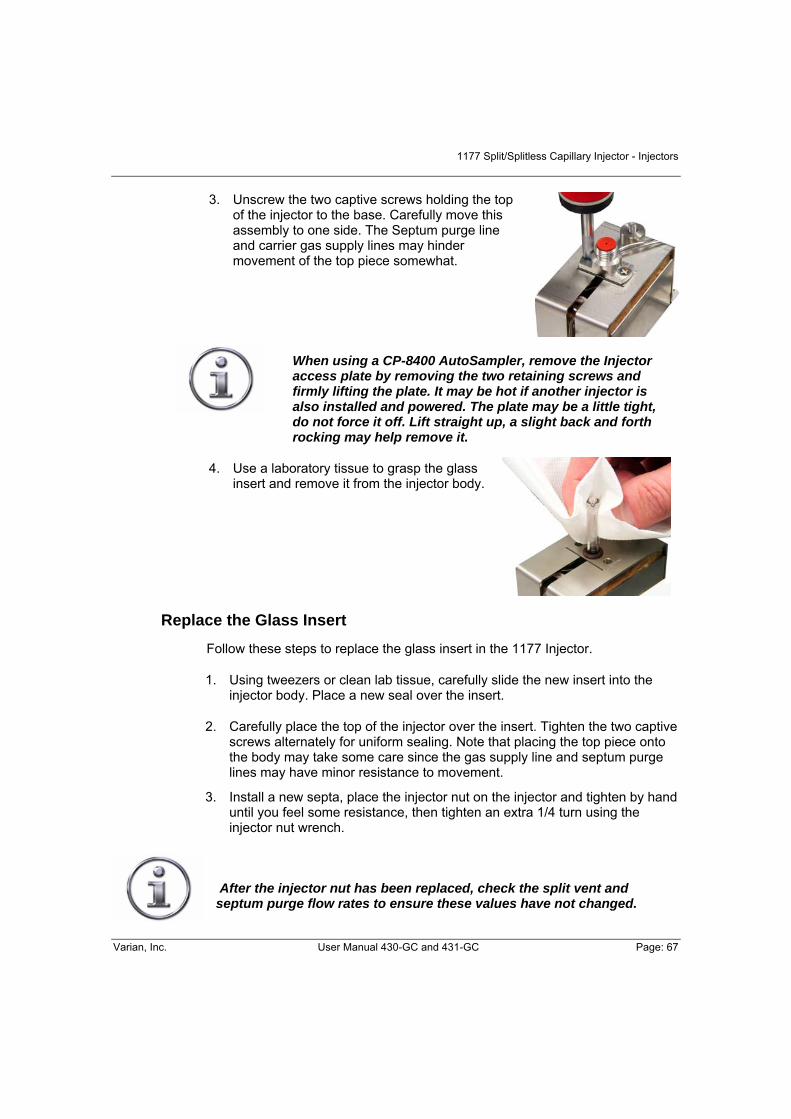
1177 Split/Splitless Capillary Injector - Injectors
Varian, Inc. User Manual 430-GC and 431-GC Page: 67
3. Unscrew the two captive screws holding the top
of the injector to the base. Carefully move this assembly to one side. The Septum purge line and carrier gas supply lines may hinder movement of the top piece somewhat.
When using a CP-8400 AutoSampler, remove the Injector access plate by removing the two retaining screws and firmly lifting the plate. It may be hot if another injector is also installed and powered. The plate may be a little tight, do not force it off. Lift straight up, a slight back and forth rocking may help remove it.
4. Use a laboratory tissue to grasp the glass insert and remove it from the injector body.
Replace the Glass Insert
Follow these steps to replace the glass insert in the 1177 Injector.
1. Using tweezers or clean lab tissue, carefully slide the new insert into the injector body. Place a new seal over the insert.
2. Carefully place the top of the injector over the insert. Tighten the two captive screws alternately for uniform sealing. Note that placing the top piece onto the body may take some care since the gas supply line and septum purge lines may have minor resistance to movement.
3. Install a new septa, place the injector nut on the injector and tighten by hand until you feel some resistance, then tighten an extra 1/4 turn using the injector nut wrench.
After the injector nut has been replaced, check the split vent and septum purge flow rates to ensure these values have not changed.
Injectors – 1177 Split/Splitless Capillary Injector
Page: 68 User Manual 430-GC and 431-GC Varian, Inc.
4. Condition the insert by setting the 1177 Injector to the split mode and purging with carrier gas for 30 min at 300°C.
Injector body cleaning
To clean the injector body, proceed as follows:
1. Set the column oven temperature to 45 °C and the 1177 injector
temperature to 50°C. Wait for the zones to reach their set temperatures and then turn the column oven off by pressing the “TURN OVEN OFF” button
located in the Column Oven section .
2. Use the 5/16” open-end wrench to loosen the capillary column nut.
3. By hand, carefully withdraw the fused silica column and nut from the injector assembly. Set the column nut and column end on the floor of the GC oven.
Use proper eye and skin protection. Methanol and acetone are toxic and flammable chemicals. Exercise appropriate precautions when these chemicals are used.
4. Remove the injector nut, septum, and top of injector.
5. Moisten a cotton swab and a stick with methanol and gently swab center of the injector body.
6. Moisten a cotton swab on a stick with iso-octane and gently swab the center of the injector body.
7. Examine the end of the fused silica column to ensure that it has not been damaged. Slide the end of the fused silica column into the opening of the injector.
8. Gently twist the column nut in the opposite direction used to tighten the nut. Place the column nut on the end of the injector and tighten the nut. This procedure minimizes twisting the column.

1177 Split/Splitless Capillary Injector - Injectors
Varian, Inc. User Manual 430-GC and 431-GC Page: 69
9. Use the 5/16″ open-end wrench and tighten with 1/6-turn to secure the column in place.
10. Replace the insert, seal, injector top, septum, and injector nut.
11. To check whether the injector is leak-tight, connect a flow meter to the split vent. Set the Relay to the split mode. If the flow meter indicates a flow less than previously measured, the injector has a leak.
Turn the column oven back on by pressing the “TURN OVEN ON” button in the
column oven section .

Injectors – 1177 Split/Splitless Capillary Injector
Page: 70 User Manual 430-GC and 431-GC Varian, Inc.
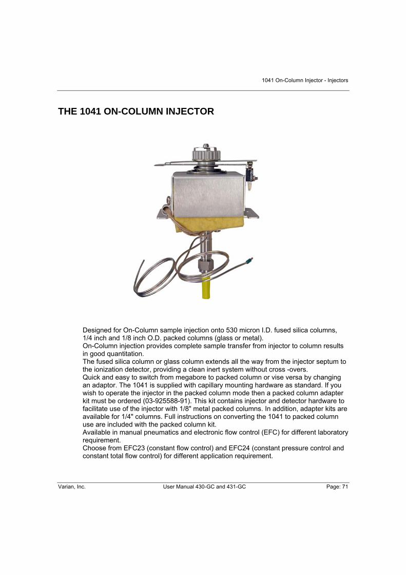
1041 On-Column Injector - Injectors
Varian, Inc. User Manual 430-GC and 431-GC Page: 71
THE 1041 ON-COLUMN INJECTOR
Designed for On-Column sample injection onto 530 micron I.D. fused silica columns, 1/4 inch and 1/8 inch O.D. packed columns (glass or metal). On-Column injection provides complete sample transfer from injector to column results in good quantitation. The fused silica column or glass column extends all the way from the injector septum to the ionization detector, providing a clean inert system without cross -overs. Quick and easy to switch from megabore to packed column or vise versa by changing an adaptor. The 1041 is supplied with capillary mounting hardware as standard. If you wish to operate the injector in the packed column mode then a packed column adapter kit must be ordered (03-925588-91). This kit contains injector and detector hardware to facilitate use of the injector with 1/8" metal packed columns. In addition, adapter kits are available for 1/4" columns. Full instructions on converting the 1041 to packed column use are included with the packed column kit. Available in manual pneumatics and electronic flow control (EFC) for different laboratory requirement. Choose from EFC23 (constant flow control) and EFC24 (constant pressure control and constant total flow control) for different application requirement.

Injectors – 1041 On-Column Injector
Page: 72 User Manual 430-GC and 431-GC Varian, Inc.
Automatic Start Switch
The automatic start switch is a spring loaded actuator that fits over, and is aligned with the injection port of the 1041 universal injector nut. The GC run is started when the actuator is depressed by the syringe barrel, or manually pressed at the moment of
sample injection. The GC run can also be manually started by pressing on the keyboard.
The injector nut and automatic start switch assembly may be very hot during instrument operation and should not be touched with unprotected hands.
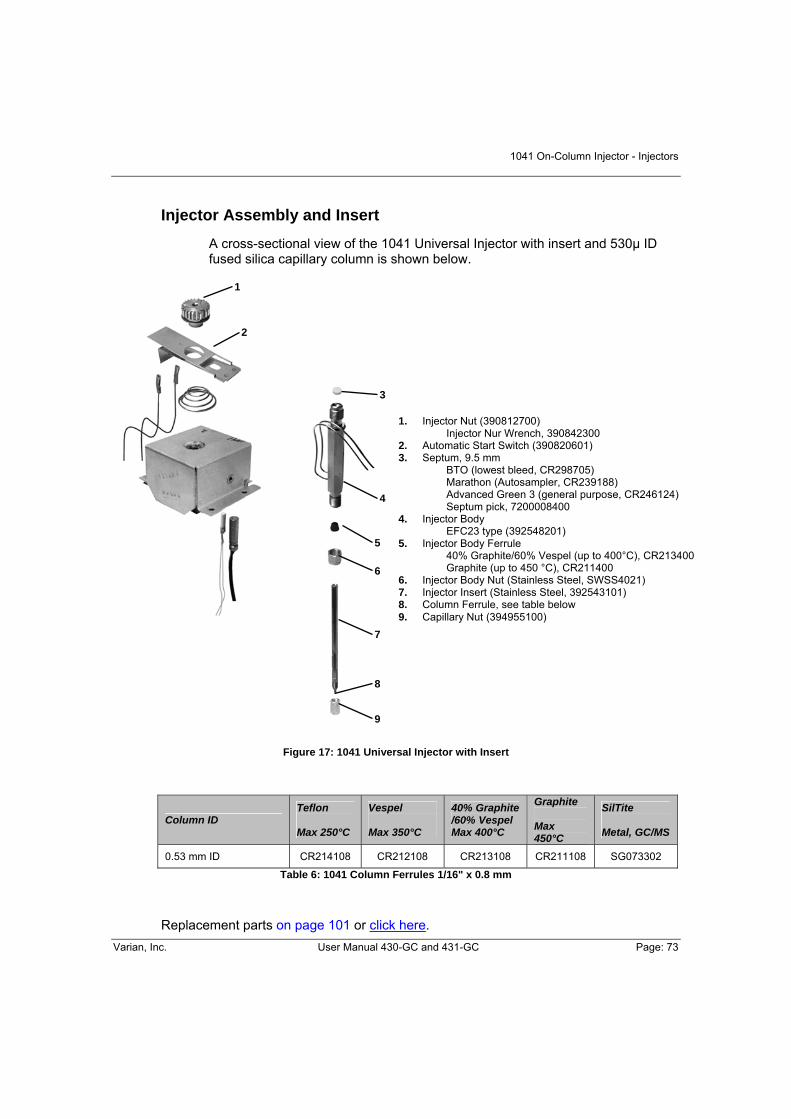
1041 On-Column Injector - Injectors
Varian, Inc. User Manual 430-GC and 431-GC Page: 73
Injector Assembly and Insert
A cross-sectional view of the 1041 Universal Injector with insert and 530µ ID fused silica capillary column is shown below.
Figure 17: 1041 Universal Injector with Insert
Column ID Teflon Max 250°C
Vespel Max 350°C
40% Graphite /60% Vespel Max 400°C
Graphite Max 450°C
SilTite Metal, GC/MS
0.53 mm ID CR214108 CR212108 CR213108 CR211108 SG073302
Table 6: 1041 Column Ferrules 1/16" x 0.8 mm
Replacement parts on page 101 or click here.
1. Injector Nut (390812700) Injector Nur Wrench, 390842300 2. Automatic Start Switch (390820601) 3. Septum, 9.5 mm BTO (lowest bleed, CR298705) Marathon (Autosampler, CR239188) Advanced Green 3 (general purpose, CR246124) Septum pick, 7200008400 4. Injector Body EFC23 type (392548201) 5. Injector Body Ferrule 40% Graphite/60% Vespel (up to 400°C), CR213400 Graphite (up to 450 °C), CR211400 6. Injector Body Nut (Stainless Steel, SWSS4021) 7. Injector Insert (Stainless Steel, 392543101) 8. Column Ferrule, see table below 9. Capillary Nut (394955100)
1
2
3
4
5
6
7
9
8

Injectors – 1041 On-Column Injector
Page: 74 User Manual 430-GC and 431-GC Varian, Inc.
Column Installation The following instructions apply to installing a 0.53 mm ID capillary column in the 1041 injector. Fused silica columns are somewhat fragile and must be handled with care. During operation, the 0.53 mm ID capillary column hangs on the capillary column holder in the column oven. To prevent the column from unwinding, weave both of the column ends through and around the column loop several times. This is particularly useful if your column is not mounted in a cage. Hang the coiled column on the capillary column holder or column stand, then prepare column end and complete column connections to both the injector and detector fittings, click here for more details on page 17.
Column connection to Injector
IMPORTANT ALIGNMENT OF THE CAPILLARY COLUMN: When a 0.53 mm ID capillary column is used in combination with the Varian 1041 injector, alignment of the column is critical. Use the following steps to precisely align the capillary column. Unless this procedure is followed, the injection syringe may damage the top of the column or peak tailing may result.
1. Install the capillary injector insert nut and the reversed ferrule on the column.
2. Uncoil about 20 cm of the injector end of the column.
3. Gently push the column fully up into the injector (approximately 9 cm), until the column comes to a firm stop. This correctly positions the column against the upper end of the injector insert. The column must go in the full distance. If it does not, the injector will not function properly. Tighten the column nut just enough to prevent column movement.
4. Manually insert the syringe that will be used with the column into the 1041
injector, checking that the syringe goes into the injector completely with no binding or interference. If interference occurs, repeat the above column insertion procedure until the syringe moves smoothly into the injector.
5. Continue to hold the column firmly in place as you tighten the column nut
carefully and only enough to hold the column firmly in place and obtain a good seal. Remove the syringe from the injector.
6. After the column is installed at the injector end, make several dry injections to
ensure that the needle enters the column easily.

1041 On-Column Injector - Injectors
Varian, Inc. User Manual 430-GC and 431-GC Page: 75
1041 Electronic Flow Control
The Electronic Flow Control module used on a 1041 injector can be type EFC23 or EFC24. The EFC23 is used to control the 1041 Injector under flow control to program the column flow. EFC23 sets a required carrier flow into the Injector/Column system. A leak in the system would be indicated to the user by a drop in inlet pressure. The EFC24 is used to control the 1041 Injector in combination with Gas or a Liquid sampling valve.
Both EFC types are designed specifically for the 1041 injector to support its various modes of operation. In simple terms it duplicates the behavior of the 1041 manual pneumatics system in that there is an inlet mass flow controller supplying carrier gas to the injector and a pressure control valve downstream from the injector which sets the injector pressure. As injector pressure determines the rate of carrier gas flow through the column, this pressure is monitored close to the point of injection. The type EFC23 flow diagram shown below is an indication of the control mechanism of this type of EFC module.
Figure 18: EFC23 Flow Diagram • See Pencil Filters on page 51
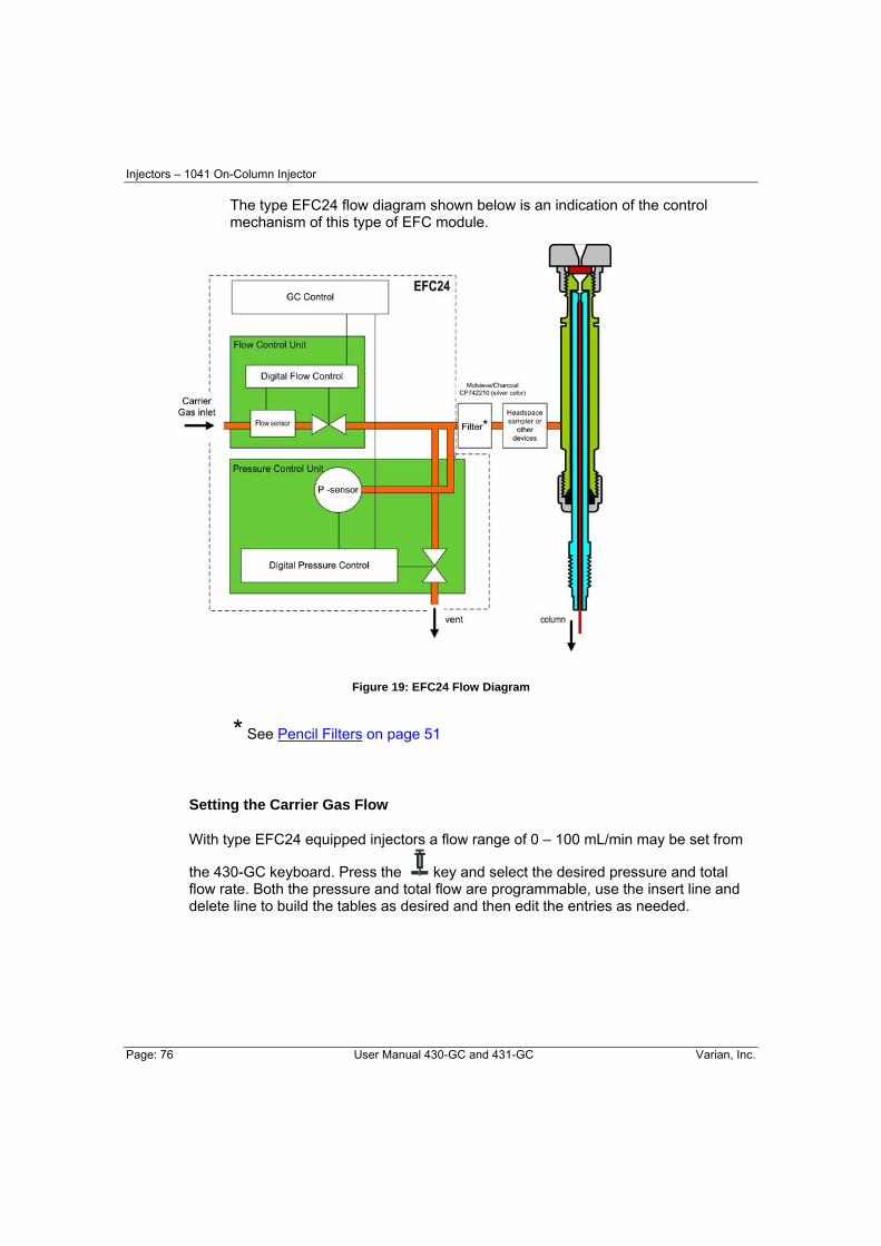
Injectors – 1041 On-Column Injector
Page: 76 User Manual 430-GC and 431-GC Varian, Inc.
The type EFC24 flow diagram shown below is an indication of the control mechanism of this type of EFC module.
Figure 19: EFC24 Flow Diagram
* See Pencil Filters on page 51
Setting the Carrier Gas Flow
With type EFC24 equipped injectors a flow range of 0 – 100 mL/min may be set from
the 430-GC keyboard. Press the key and select the desired pressure and total flow rate. Both the pressure and total flow are programmable, use the insert line and delete line to build the tables as desired and then edit the entries as needed.
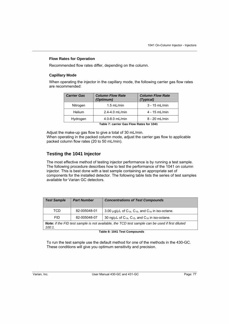
1041 On-Column Injector - Injectors
Varian, Inc. User Manual 430-GC and 431-GC Page: 77
Flow Rates for Operation
Recommended flow rates differ, depending on the column.
Capillary Mode
When operating the injector in the capillary mode, the following carrier gas flow rates are recommended:
Carrier Gas Column Flow Rate (Optimum)
Column Flow Rate (Typical)
Nitrogen 1.5 mL/min 3 - 15 mL/min
Helium 2.4-4.0 mL/min 4 - 15 mL/min
Hydrogen 4.0-8.0 mL/min 8 - 20 mL/min Table 7: carrier Gas Flow Rates for 1041
Adjust the make-up gas flow to give a total of 30 mL/min. When operating in the packed column mode, adjust the carrier gas flow to applicable packed column flow rates (20 to 50 mL/min).
Testing the 1041 Injector
The most effective method of testing injector performance is by running a test sample. The following procedure describes how to test the performance of the 1041 on column injector. This is best done with a test sample containing an appropriate set of components for the installed detector. The following table lists the series of test samples available for Varian GC detectors.
Test Sample
Part Number Concentrations of Test Compounds
TCD 82-005048-01 3.00 μg/μL of C14, C15, and C16 in iso-octane.
FID 82-005048-07 30 ng/μL of C14, C15, and C16 in iso-octane. Note: if the FID test sample is not available, the TCD test sample can be used if first diluted 100:1.
Table 8: 1041 Test Compounds
To run the test sample use the default method for one of the methods in the 430-GC. These conditions will give you optimum sensitivity and precision.

Detectors – Flame Ionization Detector (FID)
Page: 78 User Manual 430-GC and 431-GC Varian, Inc.
DETECTOR CONNECTIONS AND HARDWARE The 430-GC uses either a Flame Ionization Detector (FID) or a Thermal Conductivity Detector (TCD) to detect compounds in the effluent of the column.
Both are installed at the factory; to begin using your 430-GC you simply need to connect the following gas supplies (see FID section or TCD section as it relates to your GC):
Make-up (typically the same gas as the carrier gas) set to at least 80 psi and no more than 100 psi. Hydrogen set to 40 psi and Air set to 60 psi.
The default settings in the 430-GC for the make-up (25 mL/min), hydrogen (30 mL/min), and air (300 mL/min) are the recommended settings for those gases. If you do need to
change these gas flow rates, simply press the icon and press the key until the gas flow rate you desire to change is displayed.
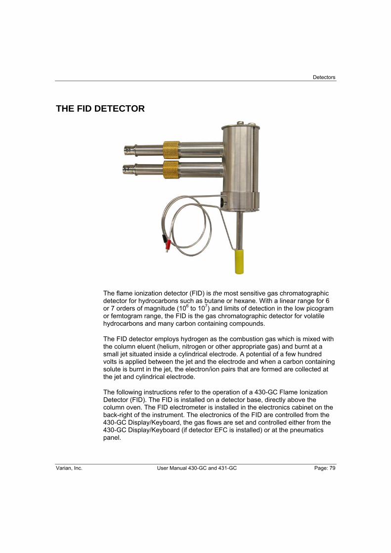
Detectors
Varian, Inc. User Manual 430-GC and 431-GC Page: 79
THE FID DETECTOR
The flame ionization detector (FID) is the most sensitive gas chromatographic detector for hydrocarbons such as butane or hexane. With a linear range for 6 or 7 orders of magnitude (106 to 107) and limits of detection in the low picogram or femtogram range, the FID is the gas chromatographic detector for volatile hydrocarbons and many carbon containing compounds.
The FID detector employs hydrogen as the combustion gas which is mixed with the column eluent (helium, nitrogen or other appropriate gas) and burnt at a small jet situated inside a cylindrical electrode. A potential of a few hundred volts is applied between the jet and the electrode and when a carbon containing solute is burnt in the jet, the electron/ion pairs that are formed are collected at the jet and cylindrical electrode.
The following instructions refer to the operation of a 430-GC Flame Ionization Detector (FID). The FID is installed on a detector base, directly above the column oven. The FID electrometer is installed in the electronics cabinet on the back-right of the instrument. The electronics of the FID are controlled from the 430-GC Display/Keyboard, the gas flows are set and controlled either from the 430-GC Display/Keyboard (if detector EFC is installed) or at the pneumatics panel.

Detectors – Flame Ionization Detector (FID)
Page: 80 User Manual 430-GC and 431-GC Varian, Inc.
Installation/Disassembly
At times, it is necessary to remove the detector components to inspect, to clean, to replace parts, or to install another detector. Follow the disassemble/reassemble instructions on the next pages for both the FID and the detector oven.
Exploded View
Figure 20: FID Exploded View
Replacement parts on page 101 or click here.
1 Signal Cable (200187700) 2 Signal Probe (200187300) 3 Ignitor Cable (392548701) 4 Ignitor Probe (200187200) 5 Screws, 8-32 x ¼” (1214200804) 6 Collector Tube (394958700) 7 Tower Screws, 8-32 x 3” (391866301) 8 Ceramic Insulator (2100003200) 9 Tower Top Plate (3400073100) 10 Detector Tower Body (100099300) 11 Flame Tip, 0.010 in. Capillary Tip (200187500) 11 Flame Tip, 0.010 in. Standard Tip (200193800) 12 Ferrule: Vespel (100%) max. 350°C (CR212200) Graphite/Vespel 40/60 max. 400°C (CR213200) Graphite (100%) max. 450°C (CR211200) 13 Aluminum Seal Washer (1500334701) 14 Detector Base (392547501) 15 Column Ferrule 16 Column Nut (394955100) --- Flow Tube (200187600) --- Large Stopper (394958600)
1
2
5
6
3
4
7
8
9
12
10
13
15
16
14
11

Detectors
Varian, Inc. User Manual 430-GC and 431-GC Page: 81
Disassemble the FID
1. Set the FID to 50 °C and wait for it to cool before disassembly. Turn the detector electronics and detector oven OFF in the active method. Remove the GC top covers on page 46.
2. Turn off the main GC gas supplies to the detector at the pneumatics panel. These are the make-up, hydrogen and air supplies.
3. Disconnect the signal and ignitor cables from their probes on the detector tower.
4. Remove the signal and ignitor probes from the detector tower. DO NOT rotate the probes as you disconnect them from the electrical contacts in the tower. Place the probes on a clean surface such as a lint-free laboratory tissue.
5. Remove the two 8-32 x 2-3/4-inch tower mounting screws from the top of detector tower. The screws should be tightened to no more than 20 inch-pounds of torque.
6. Remove the tower assembly from the detector oven, lifting straight up until clear of the flame tip. Remove the collector tube and insulator from the detector tower. Avoid contamination of the ceramic insulator and probes. If the detector is not completely cool, use a metal tool (such as tweezers or a hooked wire) to remove parts from the tower assembly. Place parts on a clean Kimwipe®. Never place them on a counter or painted surface.
7. Remove the flame-tip assembly from the detector base. Take care not to break the ceramic flame tip tube or the Vespel®/graphite or graphite ferrule.
8. Remove and discard the aluminum seal washer from the detector base. Always use a new aluminum seal washer each time you reassemble the detector. Note that the aluminum seal washer may remain in the detector tower when the tower is removed from the base.
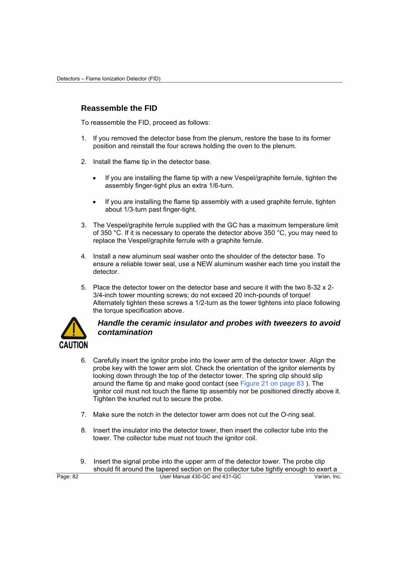
Detectors – Flame Ionization Detector (FID)
Page: 82 User Manual 430-GC and 431-GC Varian, Inc.
Reassemble the FID
To reassemble the FID, proceed as follows:
1. If you removed the detector base from the plenum, restore the base to its former position and reinstall the four screws holding the oven to the plenum.
2. Install the flame tip in the detector base.
• If you are installing the flame tip with a new Vespel/graphite ferrule, tighten the assembly finger-tight plus an extra 1/6-turn.
• If you are installing the flame tip assembly with a used graphite ferrule, tighten about 1/3-turn past finger-tight.
3. The Vespel/graphite ferrule supplied with the GC has a maximum temperature limit of 350 °C. If it is necessary to operate the detector above 350 °C, you may need to replace the Vespel/graphite ferrule with a graphite ferrule.
4. Install a new aluminum seal washer onto the shoulder of the detector base. To ensure a reliable tower seal, use a NEW aluminum washer each time you install the detector.
5. Place the detector tower on the detector base and secure it with the two 8-32 x 2-3/4-inch tower mounting screws; do not exceed 20 inch-pounds of torque! Alternately tighten these screws a 1/2-turn as the tower tightens into place following the torque specification above.
Handle the ceramic insulator and probes with tweezers to avoid contamination
6. Carefully insert the ignitor probe into the lower arm of the detector tower. Align the probe key with the tower arm slot. Check the orientation of the ignitor elements by looking down through the top of the detector tower. The spring clip should slip around the flame tip and make good contact (see Figure 21 on page 83 ). The ignitor coil must not touch the flame tip assembly nor be positioned directly above it. Tighten the knurled nut to secure the probe.
7. Make sure the notch in the detector tower arm does not cut the O-ring seal.
8. Insert the insulator into the detector tower, then insert the collector tube into the tower. The collector tube must not touch the ignitor coil.
9. Insert the signal probe into the upper arm of the detector tower. The probe clip should fit around the tapered section on the collector tube tightly enough to exert a
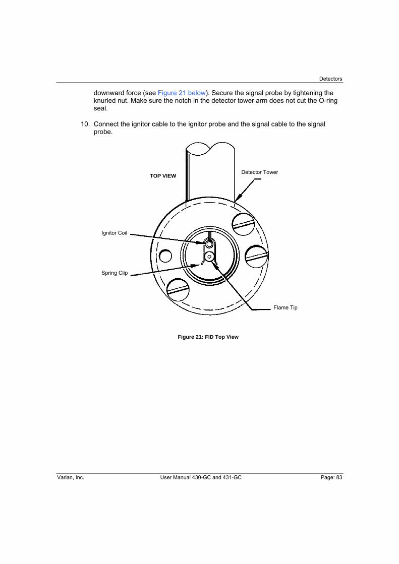
Detectors
Varian, Inc. User Manual 430-GC and 431-GC Page: 83
downward force (see Figure 21 below). Secure the signal probe by tightening the knurled nut. Make sure the notch in the detector tower arm does not cut the O-ring seal.
10. Connect the ignitor cable to the ignitor probe and the signal cable to the signal probe.
Figure 21: FID Top View
Detector Tower
Spring Clip
Ignitor Coil
TOP VIEW
Flame Tip

Detectors – Flame Ionization Detector (FID)
Page: 84 User Manual 430-GC and 431-GC Varian, Inc.

Thermal Conductivity Detector (TCD) - Detectors
Varian, Inc. User Manual 430-GC and 431-GC Page: 85
THERMAL CONDUCTIVITY DETECTOR (TCD)
A TCD detector consists of an electrically-heated wire or thermistor. The temperature of the sensing element depends on the thermal conductivity of the gas flowing around it. Changes in thermal conductivity, such as when organic molecules displace some of the carrier gas, cause a temperature rise in the element which is sensed as a change in resistance. The TCD is not as sensitive as other detectors but it is non-specific and non-destructive.
The Thermal Conductivity Detector (TCD) is mounted directly above the column oven on the 430-GC. The TCD electronic Board is installed in the electronics cabinet on the back-right side of the instrument.
TCD operating parameters are set at the 430-GC Display/Keyboard: These include carrier gas type, detector temperature, range, temperature limit, and filament temperature. The gas flows are set and controlled either from the 430-GC Display/Keyboard (if detector EFC is installed) or at the pneumatics panel.
Detectors - Thermal Conductivity Detector (TCD)
Page: 86 User Manual 430-GC and 431-GC Varian, Inc.
Initial Set-Up
To set up the TCD, proceed as follows. Note that the TCD is a two channel detector and requires both a sample flow of carrier gas and a reference flow of the same gas. Either channel can be used as the sample stream but there must always be a reference stream.
1. Connect the gas lines to the appropriate bulkhead fittings on the GC.
2. Check the gas supply pressures. Set at 80 psig.
3. Establish carrier gas flow through the Sample (right) side of the TCD and an equal Reference gas flow through the Reference (left) side of the detector. If you are using a capillary column, the total of column flow and makeup flow should equal the Reference gas flow.
4. Perform a Leak Check on both the Sample and Reference pneumatics before
proceeding to apply power to the TCD filaments. Even a small leak can supply enough oxygen to cause filament oxidation and consequent baseline drift.
5. Select then EFC and set the gas type to He, H2, or N2 based on the selected gas type. The TCD is equipped with Detector EFC. The carrier gas and detector EFC gas selections must be the same type.
6. Select the Icon and set TCD carrier gas to He/H2 for Helium or Hydrogen. For all other carrier gases, select the N2/Ar setting.

Thermal Conductivity Detector (TCD) - Detectors
Varian, Inc. User Manual 430-GC and 431-GC Page: 87
TCD Adjustments
Select Setup and set EFC Gas Type to the same type.
Setting the Filament Temperature Limit
To protect the filament, always operate the detector with the 390°C limit selected unless you require the maximum dynamic range available to the TCD
With prolonged use, the filaments slowly oxidize and their resistances increase. At some point this will cause the largest peaks in your chromatogram to become flat topped, indicating that the filament protection software has been activated. (Note that if the TCD signal is sufficiently large the output may go to zero and become unresponsive. If this occurs, adjust your injection site and conditions to avoid over range conditions). To adjust for this increase in resistance, set the Filament Temperature Limit to 490 °C, even for filament temperature set points below 390 °C. The TCD filament is automatically protected in the 430-GC. The GC turns off the filament current after four minutes if it detects that the carrier gas flow has stopped or that the filament current is low. Also, the GC turns off filament current when it detects that carrier gas is flowing through one side of the detector cell but not through the other (e.g., a septum or column is not installed, or a leak exists in one cell and not the other). If you select Helium or H2 as the carrier gas, the GC operates in the standard way to protect the TCD filament. However, because the filament protection feature in the GC operates through the detection of air (or N2) in the detector cells, the filament protection feature is disabled when you use nitrogen or argon as the carrier gas. Set the Filament Temperature Limit to 390 °C or 490 °C, according to the highest filament temperature setpoint required. With the Limit set to 390 °C, the peak sample filament temperature is limited to approximately 450 °C. The temperature limit is approximately 550 °C at the 490 °C setting. The 450 °C limit protects filaments from oxidation when exposed to air over an extended period of time. However, at the 550 °C temperature limit the filament can degrade after only a few minutes.

Detectors - Thermal Conductivity Detector (TCD)
Page: 88 User Manual 430-GC and 431-GC Varian, Inc.
If you select N2/Ar as the carrier gas, the filament protection feature is disabled. Because the GC does not turn off the filament current, the TCD filaments can rapidly oxidize if you operate the TCD filament temperature above 390 °C without carrier gas flowing through the TCD cells. If you plan to operate the TCD after the carrier gas has been turned off, purge the air from the TCD cells with carrier gas for five minutes before operating the TCD.
Operation
To operate, the TCD requires only carrier gas. Helium or hydrogen is recommended as carrier gases. You can use nitrogen as a carrier gas, but you may lose some sensitivity and see an increase in the detector noise.
If hydrogen is used as a carrier gas, vent the hydrogen from the TCD to a safe place. Hydrogen is very flammable.
Before Operating the TCD
Do not operate the TCD until you have connected carrier gas to both inlets of the TCD. The TCD accommodates two columns (a column for the reference cell and a column for the detector cell) or a column and a reference line. The columns can be packed or capillary columns and you can combine a capillary column with a packed column. To avoid contaminating the detector, condition all packed columns before you connect them to the TCD. For the following discussion, assume that the analytical column is attached to the right side of the TCD and the reference column or reference gas supply to the left side of the TCD. However, you can configure the GC with the analytical column connected to the left side of the TCD, simply reverse the TCD polarity.
If you plan to operate the TCD after the carrier gas has been turned off for an extended period of time, turn on the carrier gas for five minutes before turning on the filament current to purge air from the system. This prevents oxidation of the TCD filaments.

Thermal Conductivity Detector (TCD) - Detectors
Varian, Inc. User Manual 430-GC and 431-GC Page: 89
At the factory, the carrier gas flow rate for TCD is set at 30 mL/min. (Carrier gas: He) through both sides of the detector. The carrier gas flow rate is measured at the two exit ports on the TCD. Once the carrier gas is flowing through the TCD, set up the TCD for operation as follows: 1. Set the TCD oven to the desired temperature and allow it to come to the setpoint.
Usually, set the TCD temperature at least 20°C higher than the maximum temperature the column oven reaches in your analysis.
2. Set TCD filament temperature in the detector section. A filament temperature 50°C
above the detector temperature should provide a good starting point for most applications. Turn the TCD Electronics ON to begin heating the filaments.
3. Allow system to equilibrate 10 to 15 minutes.
4. Monitor the filament current through the detector status display. Initially, the current
is greater than the final operating current. Gradually, however, the current decreases as the detector thermally equilibrates. For best performance of the detector, do not permit the filament temperature to exceed the detector temperature by more than 200 °C. Generally, use the lowest detector current possible for the sensitivity your application requires.
5. Set the initial Autozero to OFF. Set Autozero to NO, then select the Command icon
followed by Autozero Now. Monitor the signal on the detector status display. A continuous drift, either positive or negative, may indicate an air leak in either the carrier or reference gas stream.
6. Note that it is normal for the TCD baseline to drift until the detector thermally
equilibrates. The time it takes to reach equilibrium always exceeds the time it takes for the detector oven to reach its temperature. When the baseline is stable, you can begin your analysis. Autozero is automatically disabled when the GC method is in RUN.
Change Initial Autozero back to YES. This allows the system to balance the bridge automatically before each run for maximum dynamic range. The current status of the balance control, from -99% to +99%, is shown on the display. A continuous drift in the balance value over time may indicate you have an air leak which is causing one set of filaments to oxidize, changing their resistance and unbalancing the detector bridge. Range Setting
Use the 0.05 mV range in the following cases:
• Low currents (100-150 mA) • High Currents (300 mA) • Output Signal Fed to Computer or Integrator

Detectors - Thermal Conductivity Detector (TCD)
Page: 90 User Manual 430-GC and 431-GC Varian, Inc.
Low Currents (100-150 mA)
Analyses that had required a high filament current and a less sensitive range can often be performed at lower currents and a more sensitive range. For example, a filament current of 120 mA and a range of 0.05 mV yields about the same output signal as a filament current of 300 mA and a range of 0.5 mV. At the lower current, the detector noise is lower, the stability is higher, and the filament lifetime is extended. Thus, Varian recommends that, whenever possible, you operate the TCD at the lowest practical filament current.
The chromatograms illustrate the high sensitivity and detectivity (18 ppm of Neon in air) that is possible with the TC Detector. Also, a comparison of chromatogram A with chromatogram B shows that with the use of the bridge output signal amplifier, you can obtain the same analytical results at half the filament current, thereby extending the lifetime of the TCD filament. The Neon peak in chromatogram C illustrates how you can use a high filament current (300 mA) with a high amplification setting to increase the effective sensitivity of the TCD.
Figure 22: TCD Sensitivity and Amplification
1 Ne 2 O2 3 N2
A. Filament current: 290 mA Filament temperature: 300 °C At 1.5 minutes, range and attenuation changes from 2 x 0.5 mV to 128 x 5.0 mV. B. Filament current: 151 mA Filament temperature: 160 °C At 1.5 minutes, range and attenuation changes from 2 x 0.05 mV to 128 x 0.5 mV. C. Filament current: 299 mA Filament temperature: 300 °C At 1.5 minutes, range and attenuation changes from 4 x 0.05 mV to 128 x 5.0 mV. Conditions: Carrier gas: He Sample: Air, 2 mL Column: 10 ft. molecular sieve 5A 30/60 mesh at 50 °C Injection: Gas sample valve TCD oven temperature: 120 °C

Thermal Conductivity Detector (TCD) - Detectors
Varian, Inc. User Manual 430-GC and 431-GC Page: 91
High Currents (300 mA)
To obtain the highest possible sensitivity, operate the TCD at the 0.05 mV range with a high filament current. In this configuration, TCD noise is primarily noise derived from filament vibration and fluctuations in carrier gas flow through the detector. However, at high filament currents, the detector is very susceptible to air leaks into the gas lines, improperly conditioned columns, imbalanced reference and analytical flow rates, or impure carrier gas supply, which cause the baseline to drift. Baseline drift from any of these sources generally increases as the absolute filament temperature increases. Therefore, operate the TCD with as low a filament current as practical for your application.
Also, operate the TCD with the lowest filament and detector temperatures appropriate. If possible, avoid operating the TCD with a filament temperature greater than 390 °C. To operate the TCD with filament temperatures between 390 °C and 490 °C, set the Filament Temperature Limit to 490 °C. See Figure 22 on page 90 for an example of the performance of the TCD at a high current.
Calculate Detector Sensitivity
To calculate the sensitivity of the TCD, proceed as follows:
EXAMPLE 1: Known Sample Weight
S = PFC/W Where:
S = Sensitivity in mV x mL/mg P = Integrated peak area in mV x min W = Weight of sample in carrier gas in mg
FC = Carrier gas flow in mL/min corrected to detector temp FC = FO (TD/TA)(1-PW/PA)
Where: FO = Flow rate measured at detector outlet (at ambient temperature) in mL/min. TD = Detector temperature in °K TA = Ambient temperature in °K PW = Partial pressure of H2O at ambient temperature in torr PA = Ambient pressure in torr
Note: The (1-PW /PA) expression applies only if using a bubble flowmeter.

Detectors - Thermal Conductivity Detector (TCD)
Page: 92 User Manual 430-GC and 431-GC Varian, Inc.
EXAMPLE 2: Known Concentration of Sample in Detector
S = E/CD Where:
S = Sensitivity in mV x mL/mg E = Detector signal (peak height) in mV CD = Concentration of test substance in the measured peak volume in mg/mL
Peak volume = Peak width at half height (in min.) x gas flow rate at detector (in mL/min) = W • h/2 x FC
Calculate Detector Detectivity
To calculate the detectivity of the TCD, proceed as follows:
Detectivity 2 x NoiseSensitivity=
Reverse Polarity
If you inject a standard or sample into the reference side of the TCD, peaks appear in the negative direction. If you want to integrate or process these peaks with a data system, you must convert the polarity of the peaks from negative to positive. Reference the TCD section to set initial detector polarity either Positive or Negative.
You can also time program when you would like the polarity to be automatically reversed during a chromatographic run. Set a time-programmed polarity reversal in the detector method section.
Adjust TCD Carrier Gas Flow Rates
All 430-GCs equipped with TCDs are factory tested at the flow rate listed below. Adjustments to the carrier gas flow rate are made using the Injector icon for column flow and Detector icon for makeup and/or reference flow.
Carrier Gas: Helium Inlet Pressure: 80 psig Purity: 99.999% Column Flow Rate: 30 mL/min Reference Column Flow Rate: 30 mL/min
Note: Tightly cap gas filters when not used. Prolonged exposure of the contents of the filter to room air degrades the performance of the filters.
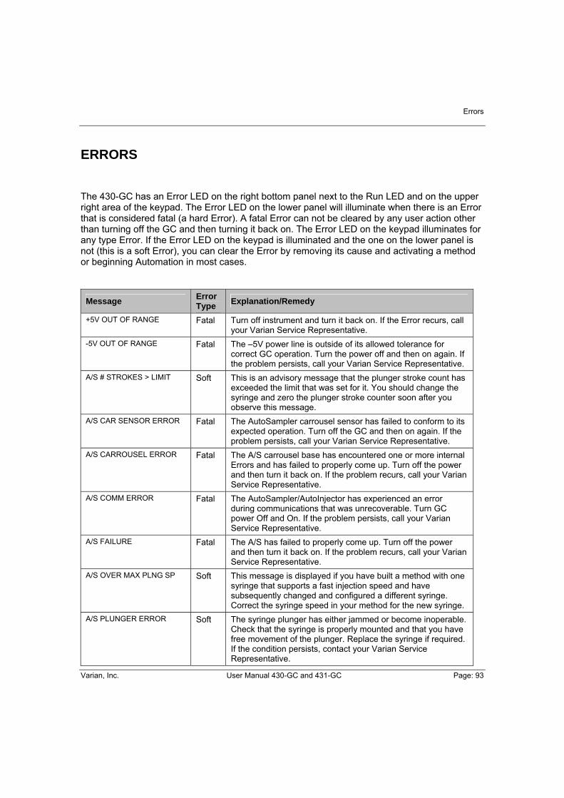
Errors
Varian, Inc. User Manual 430-GC and 431-GC Page: 93
ERRORS The 430-GC has an Error LED on the right bottom panel next to the Run LED and on the upper right area of the keypad. The Error LED on the lower panel will illuminate when there is an Error that is considered fatal (a hard Error). A fatal Error can not be cleared by any user action other than turning off the GC and then turning it back on. The Error LED on the keypad illuminates for any type Error. If the Error LED on the keypad is illuminated and the one on the lower panel is not (this is a soft Error), you can clear the Error by removing its cause and activating a method or beginning Automation in most cases.
Message Error Type Explanation/Remedy
+5V OUT OF RANGE Fatal Turn off instrument and turn it back on. If the Error recurs, call your Varian Service Representative.
-5V OUT OF RANGE Fatal The –5V power line is outside of its allowed tolerance for correct GC operation. Turn the power off and then on again. If the problem persists, call your Varian Service Representative.
A/S # STROKES > LIMIT Soft This is an advisory message that the plunger stroke count has exceeded the limit that was set for it. You should change the syringe and zero the plunger stroke counter soon after you observe this message.
A/S CAR SENSOR ERROR Fatal The AutoSampler carrousel sensor has failed to conform to its expected operation. Turn off the GC and then on again. If the problem persists, call your Varian Service Representative.
A/S CARROUSEL ERROR Fatal The A/S carrousel base has encountered one or more internal Errors and has failed to properly come up. Turn off the power and then turn it back on. If the problem recurs, call your Varian Service Representative.
A/S COMM ERROR Fatal The AutoSampler/AutoInjector has experienced an error during communications that was unrecoverable. Turn GC power Off and On. If the problem persists, call your Varian Service Representative.
A/S FAILURE Fatal The A/S has failed to properly come up. Turn off the power and then turn it back on. If the problem recurs, call your Varian Service Representative.
A/S OVER MAX PLNG SP Soft This message is displayed if you have built a method with one syringe that supports a fast injection speed and have subsequently changed and configured a different syringe. Correct the syringe speed in your method for the new syringe.
A/S PLUNGER ERROR Soft The syringe plunger has either jammed or become inoperable. Check that the syringe is properly mounted and that you have free movement of the plunger. Replace the syringe if required. If the condition persists, contact your Varian Service Representative.

Errors
Page: 94 User Manual 430-GC and 431-GC Varian, Inc.
Message Error Type Explanation/Remedy
A/S PLUNGER SENS ERR Fatal The AutoSampler plunger sensor has failed to conform to its expected operation. Turn off the GC and then on again. If the problem persists, call your Varian Service Representative.
A/S SYR SENSOR ERR Fatal The AutoSampler syringe sensor has failed to conform to its expected operation. Turn off the GC and then on again. If the problem persists, call your Varian Service Representative.
A/S SYR VOL EXCEEDED Soft The total volume of the sample, air gaps (if any), solvent plugs (if any), and internal standards (if any) exceeds the capacity of the configured syringe. Note that this error is only sensed at the time of injection. Check your method and correct any volumes that are excessive.
A/S SYRINGE MISSING Soft The AutoSampler has sensed that the syringe is not installed. Check that you have a syringe installed. If the condition persists, contact your Varian Service Representative.
A/S SYRINGE SLED ERR Soft The syringe sled is either jammed or miscalibrated. Recalibrate your vial and injector positions making certain that the syringe sled has a small clearance (consult your manual) above vials and does not compress the injector switch on the injector. If, after adjusting the syringe sled height you still observe this problem, call your Varian Service Representative.
A/S TOWER ERROR Fatal The A/S tower has one or more internal Errors and has failed to properly come up. Turn off the power and then turn it back on. If the problem recurs, call your Varian Service Representative.
A/S TRAY MISSING Soft The CP-8410 sample tray has been removed from the base. Replace the tray; the CP-8410 should automatically sense that the tray has been replaced. If the message persists call your Varian Service Representative.
A/S TWR SENSOR ERROR Fatal The tower sensor does not conform to its expected operation. Turn the GC off and then on again. If the problem persists, call your Varian Service Representative.
A/S VIAL MISSING Soft The AutoSampler has failed to detect a vial within an expected range of vials. This message is an advisory message. If you have a vial in the position and it has been missed, check that a septum is installed. Lack of a septum and dark colors may cause the tower sensor to fail to identify the vial.
A/S VIAL SENSOR ERR Fatal The AutoSampler vial sensor has failed to conform to its expected operation. Turn off the GC and then on again. If the problem persists, call your Varian Service Representative.
A/S VIAL UNREACHABLE Soft This message informs you that the CP-8410 tray is oriented such that the requested sample vial does not fall under the arc of the tower. Re-orient the tray or change the requested vial from which you intend to inject to correct this.

Errors
Varian, Inc. User Manual 430-GC and 431-GC Page: 95
Message Error Type Explanation/Remedy
ADC CALIB FAILURE Fatal The DAC (Digital to Analog Converter) that supplies the analog output signal failed to calibrate within its set tolerance. Turn off the power and then turn it back on. If the problem is observed again either immediately or within a short period of time call your Varian Service Representative.
COL RESPNSE TOO FAST Fatal Turn off instrument and turn it back on. If the Error recurs, call your Varian Service Representative.
COL RESPNSE TOO SLOW Fatal Turn off instrument and turn it back on. If the Error recurs, call your Varian Service Representative.
COL TEMP PROBE OPEN Fatal Turn off instrument and turn it back on. If the Error recurs, call your Varian Service Representative.
COL TEMP PROBE SHORT Fatal Turn off instrument and turn it back on. If the Error recurs, call your Varian Service Representative.
COL TEMP TOO LOW Fatal Turn off instrument and turn it back on. If the Error recurs, call your Varian Service Representative
COL THERMAL RUNAWAY Fatal Turn off instrument and turn it back on. If the Error recurs, call your Varian Service Representative.
DAC CALIB FAILURE Soft Activate a method to clear this Error. If the Error recurs, turn the GC off and then on. If the Error persists, call your Varian Service Representative.
DET RESPNSE TOO FAST Fatal Turn off instrument and turn it back on. If the Error recurs, call your Varian Service Representative.
DET RESPNSE TOO SLOW Fatal Turn off instrument and turn it back on. If the Error recurs, call your Varian Service Representative.
DET TEMP PROBE OPEN Fatal Turn off instrument and turn it back on. If the Error recurs, call your Varian Service Representative.
DET TEMP PROBE SHORT Fatal Turn off instrument and turn it back on. If the Error recurs, call your Varian Service Representative.
DET TEMP TOO LOW Fatal The detector oven temperature is below the allowed temperature. Turn the GC off and then on again. If the problem persists, call your Varian Service Representative.
DIAG TEMP ERROR Fatal The actual temperature of a temperature controlled resistor block used for automatic instrument calibration has exceeded its allowed temperature set point. Turn the power to the GC off and then on again. If the problem persists, call your Varian Service Representative.
FAN UNPLUGGED IN RUN Fatal Turn off instrument and turn it back on. If the Error recurs, call your Varian Service Representative.

Errors
Page: 96 User Manual 430-GC and 431-GC Varian, Inc.
Message Error Type Explanation/Remedy
FID FLAME OUT Soft The FID flame has been quenched. The flame detection is based on a background signal intensity of approximately 330 microvolts. It is possible for very clean GC systems to have baselines less than 330 microvolts causing spurious flameout messages. If you suspect that the flameout message is spurious, use a shiny, cool metal object (such as a box end wrench) and hold it just above the FID tower being careful not to get too close to the hot surfaces. If you observe condensation then the flame is still lit; you may wish to change your fuel gas mixture or some other operating characteristic that would allow a slightly higher background signal. Once a flame out is detected, the system will attempt to ignite the flame 3 times before reporting the flame out condition. The Error is cleared by either igniting the flame using the Ignite FID Flame! Command or by turning the Detector electronics off.
FLOW > MAX DEFC FLOW Fatal Turn off instrument and turn it back on. If the Error recurs, call your Varian Service Representative.
GAS SAVER TIMEOUT Soft The GC has been idle for a period of time equal to or greater than the set Gas Saver timeout period. Activate a method to clear the Error.
INJ RESPNSE TOO FAST Fatal Turn off instrument and turn it back on. If the Error recurs, call your Varian Service Representative.
INJ RESPNSE TOO SLOW Fatal Turn off instrument and turn it back on. If the Error recurs, call your Varian Service Representative.
INJ TEMP PROBE OPEN Fatal Turn off instrument and turn it back on. If the Error recurs, call your Varian Service Representative.
INJ TEMP PROBE SHORT Fatal Turn off instrument and turn it back on. If the Error recurs, call your Varian Service Representative.
INJ TEMP TOO LOW Fatal Turn off instrument and turn it back on. If the Error recurs, call your Varian Service Representative.
INJ THERMAL RUNAWAY Fatal Turn off instrument and turn it back on. If the Error recurs, call your Varian Service Representative.
INTERNAL TEMP EXCDED Fatal Turn off instrument and turn it back on. If the Error recurs, call your Varian Service Representative.
IOP COMM FAILURE Fatal Turn off instrument and turn it back on. If the Error recurs, call your Varian Service Representative.
MAIN BOARD FAILURE Fatal Turn off instrument and turn it back on. If the Error recurs, call your Varian Service Representative.
RUN ENDED BEFORE INJ Soft The AutoSampler failed to complete the injection sequence. Restart Automation to clear the Error. If the problem recurs, call your Varian Service Representative.
START AFTER INJ FAIL Soft Restart Automation to clear this Error. If it recurs, check that the inject switch installed on the injector nut is functioning properly. Call your Varian Service Representative if the problem persists.

Errors
Varian, Inc. User Manual 430-GC and 431-GC Page: 97
Message Error Type Explanation/Remedy
STEP MOTOR ERROR Fatal The column oven vent stepper motor has failed to reach its internally set position within the step tolerance. Turn the power off and then on again. If the problem persists call your Varian Service Representative.
TEMP > MAX COL SETUP Soft Change either temperature limit or the programmed temperature and re-activate the method.
TEMP > MAX COL TEMP Fatal Turn off instrument and turn it back on. If the Error recurs, call your Varian Service Representative.
TEMP > MAX DET SETUP Soft Change either temperature limit or the programmed temperature and re-activate the method.
TEMP > MAX DET TEMP Fatal Turn off instrument and turn it back on. If the Error recurs, call your Varian Service Representative.
TEMP > MAX INJ SETUP Soft Change either temperature limit or the programmed temperature and re-activate the method.
TEMP > MAX INJ TEMP Fatal Turn off instrument and turn it back on. If the Error recurs, call your Varian Service Representative.

Errors
Page: 98 User Manual 430-GC and 431-GC Varian, Inc.
Shipping, Cleaning and Disposal Instructions
Varian, Inc. User Manual 430-GC and 431-GC Page: 99
SHIPPING, CLEANING AND DISPOSAL INSTRUCTIONS
SHIPPING INSTRUCTIONS If your 430-GC for any reason must send back to the nearest Varian, Inc. subsidiary or Varian, Inc. representative, it is very important to follow these additional preparation instructions:
1. Place the shipping restrain pin back.
2. Put protection plugs on the sample and/or carrier gas inlets.
3. Remove columns.
CLEANING INSTRUCTIONS
To keep the 430-GC surface clean, refer to the remarks given below:
• Switch the 430-GC off. • Remove the power cable. • Put protection plugs on the sample and carrier gas inlets. • Put protection plugs on the Column vents. • Use a soft (no hard or abrasive) brush to carefully brush away all dust and
dirt. • If the outer case is dirty (never clean the inside!) clean it with a soft, clean
cloth dampened with mild detergent. • Never use alcohol or thinners to clean the 430-GC, these chemicals can
damage the case. • Be careful not to get water on the electronic components. • Do not use compressed air to clean.
DISPOSAL INSTRUCTIONS
When the lifetime of the 430-GC or parts of it has reached the end of its useful life, disposal must be carried out in accordance with all (environment) regulations applicable in your country.

Shipping, Cleaning and Disposal Instructions
Page: 100 User Manual 430-GC Varian, Inc.
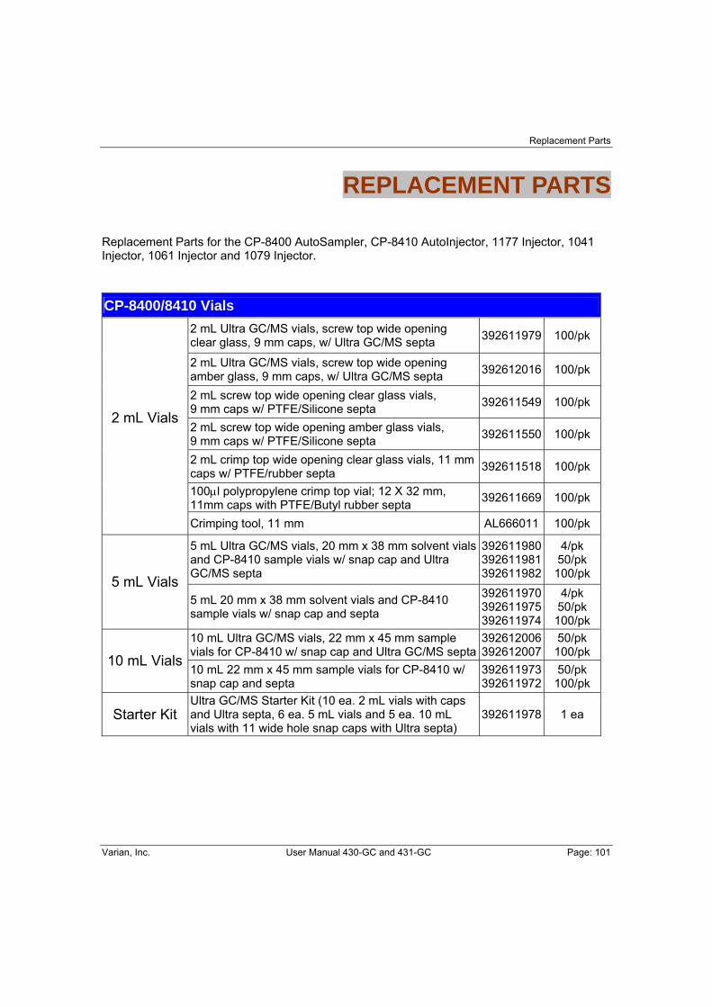
Replacement Parts
Varian, Inc. User Manual 430-GC and 431-GC Page: 101
REPLACEMENT PARTS
Replacement Parts for the CP-8400 AutoSampler, CP-8410 AutoInjector, 1177 Injector, 1041 Injector, 1061 Injector and 1079 Injector. CP-8400/8410 Vials
2 mL Ultra GC/MS vials, screw top wide opening clear glass, 9 mm caps, w/ Ultra GC/MS septa 392611979 100/pk
2 mL Ultra GC/MS vials, screw top wide opening amber glass, 9 mm caps, w/ Ultra GC/MS septa 392612016 100/pk
2 mL screw top wide opening clear glass vials, 9 mm caps w/ PTFE/Silicone septa 392611549 100/pk
2 mL screw top wide opening amber glass vials, 9 mm caps w/ PTFE/Silicone septa 392611550 100/pk
2 mL crimp top wide opening clear glass vials, 11 mm caps w/ PTFE/rubber septa 392611518 100/pk
100μl polypropylene crimp top vial; 12 X 32 mm, 11mm caps with PTFE/Butyl rubber septa 392611669 100/pk
2 mL Vials
Crimping tool, 11 mm AL666011 100/pk
5 mL Ultra GC/MS vials, 20 mm x 38 mm solvent vials and CP-8410 sample vials w/ snap cap and Ultra GC/MS septa
392611980 392611981 392611982
4/pk 50/pk 100/pk 5 mL Vials
5 mL 20 mm x 38 mm solvent vials and CP-8410 sample vials w/ snap cap and septa
392611970 392611975 392611974
4/pk 50/pk 100/pk
10 mL Ultra GC/MS vials, 22 mm x 45 mm sample vials for CP-8410 w/ snap cap and Ultra GC/MS septa
392612006 392612007
50/pk 100/pk
10 mL Vials 10 mL 22 mm x 45 mm sample vials for CP-8410 w/ snap cap and septa
392611973 392611972
50/pk 100/pk
Starter Kit Ultra GC/MS Starter Kit (10 ea. 2 mL vials with caps and Ultra septa, 6 ea. 5 mL vials and 5 ea. 10 mL vials with 11 wide hole snap caps with Ultra septa)
392611978 1 ea

Replacement Parts
Page: 102 User Manual 430-GC and 431-GC Varian, Inc.
CP-8400/8410 Syringes
Hamilton 5 μL 701 syringe, 26 gauge HM87900 1 ea 5 µL
SGE 5 μL syringe, conical tip needle, 26 gauge 392590204 1 ea
Hamilton 10 μL 701N syringe, 26 gauge HM80300 HM80366
1 ea 6/pk
Hamilton 10 μL 701 syringe, conical tip needle, 26 ga. SK0163520 1 ea 10 µL
SGE 10 μL syringe, conical tip needle, 26 gauge SG002980 1 ea 100 µL SGE 100 μL syringe, Teflon tip, removable needle SG005333 1 ea
CP-8400/8410 Replacement Trays
CP-8400 AutoSampler 100-vial Sample Tray CP738642 1 ea
CP-8410 AutoInjector Sample Tray CP739656 1 ea
Quick Connect Ferrules and Column Scales
Graphite Quick Connect ferrules w/ brass jackets (not for use connecting to MS detector) 0.4 mm, for 0.25 mm ID columns 0.5 mm, for 0.32 mm ID columns 0.8 mm, for 0.53 mm ID columns
392538401 392538402 392538403
2/pk 2/pk 2/pk
3800/3900 Column insertion scale 392575001 1 ea 1041 Injector
Insert Insert for 0.53 mm ID columns 392543101 1 ea
10.0 mm BTO Centerguide septa CR298745 50/pk Septa
9.5 mm Advanced Green 3 Centerguide septa CR246124 50/pk 9.5 mm Marathon Centerguide septa CR239188 25/pk
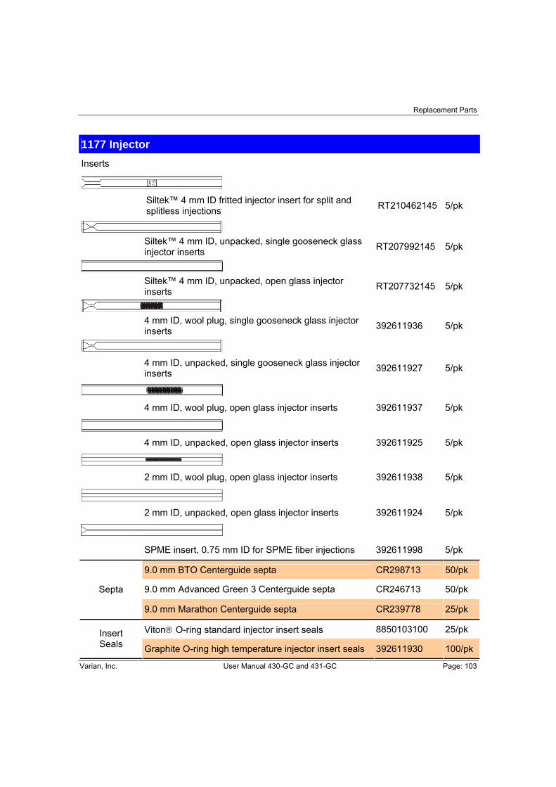
Replacement Parts
Varian, Inc. User Manual 430-GC and 431-GC Page: 103
1177 Injector
Inserts
Siltek™ 4 mm ID fritted injector insert for split and
splitless injections RT210462145 5/pk
Siltek™ 4 mm ID, unpacked, single gooseneck glass
injector inserts RT207992145 5/pk
Siltek™ 4 mm ID, unpacked, open glass injector
inserts RT207732145 5/pk
4 mm ID, wool plug, single gooseneck glass injector
inserts 392611936 5/pk
4 mm ID, unpacked, single gooseneck glass injector
inserts 392611927 5/pk
4 mm ID, wool plug, open glass injector inserts 392611937 5/pk
4 mm ID, unpacked, open glass injector inserts 392611925 5/pk
2 mm ID, wool plug, open glass injector inserts 392611938 5/pk
2 mm ID, unpacked, open glass injector inserts 392611924 5/pk
SPME insert, 0.75 mm ID for SPME fiber injections 392611998 5/pk
9.0 mm BTO Centerguide septa CR298713 50/pk
9.0 mm Advanced Green 3 Centerguide septa CR246713 50/pk Septa
9.0 mm Marathon Centerguide septa CR239778 25/pk
Viton® O-ring standard injector insert seals 8850103100 25/pk Insert Seals Graphite O-ring high temperature injector insert seals 392611930 100/pk

Replacement Parts
Page: 104 User Manual 430-GC and 431-GC Varian, Inc.