Embed Size (px)
Citation preview
Varian 400-DS AutomatedApparatus 7 Operator’s
Manual
P/N 70-9051November 2010Revision B
Limitation of Liability
The information in this document is subject to change without notice. Varian, Inc. makes no warranty of any kind with regard to this material, including, but not limited to, the implied warranties or merchantability and fitness for a particular purpose. Varian, Inc. shall not be liable for errors contained herein or for incidental consequential damages in connection with the furnishing, performance or use of this material.
All rights are reserved. Reproduction, adaptation or translation without prior written permission is prohibited, except as allowed under copyright laws.
First Edition (November 2010)Varian 400-DS Automated Apparatus 7 Operator’s ManualPart Number 70-9051 Revision BPrinted in the United States of America
The following terms are trademarks of Varian, Inc.:
All other trademarks are property of their respective owners.
Varian, Inc.13000 Weston ParkwayCary, North Carolina 27513-2250800.229.1108919.677.1108Fax: 919.677.1138www.varianinc.com
Copyright (c) 2007 - 2010 by Varian, Inc.
• BenchsaverTM
• BIO-DIS III®
• Enhancer Cell®
• Full Flow FiltersTM
• Peak VesselTM
• Practical Solutions®
• QA and QAIITM
• TruCenterTM
• VanKel®
• VK®
Varian, Inc.
Table of Contents
Chapter 1 Safety Practices and Hazards 11
Electrical Hazards 12
Reciprocation Hazard 13Other 13Warning 13General 15
WEEE Directive 17
Chapter 2 Introduction 19
Conventions Used in this Manual 20
USP Physical Parameters 20
Specifications 21Environmental Specifications 21Engineering Specifications 21
Accessories 23
Table of Contents
Varian, Inc.
Chapter 3 Installation and Setup 25
Unpacking Your Equipment 25
Leveling Your Apparatus 26
Electrical Connection 27
Setting up Your PC 28
Cable Connections 29Single System Setup 29Multiple System Setup 29
Setting Up the Varian 400-DS 30
Initial Power Up 32
Software Installation 32Attaching the Database 33Local Security Policy 35E-mail Notification Configuration (Optional) 37
Starting 400-DS Workstation 40
Dissolution Server Selection 41
Configuring the Application - Adding Users 43
Chapter 4 Operation 47
Log on to the Varian 400-DS Workstation 47
Configuring Your System 50Copying a System Configuration 54Deleting a System Configuration 54Serial Numbers 55System Configuration Report 56Editing an Existing System Configuration 56Import/Export XML File 58
System Calibration 60Cell Calibration Temperatures 62
Manual Control/Diagnostics 64Verifying Sample Tray Control 65
Varian, Inc.
Table of Contents
Media Control 66Verifying the Cell Temperature 67Reciprocation 68Controlling the Evaporation Cover 69
Method Editor 69Creating a Method 70Copying Methods 77Deleting Methods 77Editing an Existing Method 78Method Report 78Audit Trail 79Import/Export XML File 80
Running the Method 82
Test Reports 87Electronic Signatures 88
Clean System 88
Chapter 5 Maintenance 89
Routine Maintenance (to be Performed Between Each Dissolution Method 90
Sample Holders 90
Non-Routine Maintenance (to be Performed at Pre-Determined Intervals) 91
Chapter 6 Service and Warranty 93
Exclusions and Limitations 94
Obtaining Warranty Service 94
Warranty Limitations 94
Exclusive Remedies 95
Index 97
Tell Us How We Are Doing 101
Table of Contents
Varian, Inc.
This page was intentionally left blank, except for this message.
Varian, Inc.
List of Figures
FIGURE 1. Accessory Tray 1 24
FIGURE 2. Accessory Tray 2 24
FIGURE 3. Diagram of the electrical connection 27
FIGURE 4. Diagram of cable connections 29
FIGURE 5. License dongle 33
FIGURE 6. MSDE Manager screen 34
FIGURE 7. DissoService Manager screen 37
FIGURE 8. Tools menu 38
FIGURE 9. DissoService Options screen 39
FIGURE 10. Logon screen 41
List of Figures
Varian, Inc.
FIGURE 11. Add New Dissolution Server screen 42
FIGURE 12. Browse Dissolution Servers screen 42
FIGURE 13. Configuration Dialog screen 43
FIGURE 14. Local Users and Groups screen 44
FIGURE 15. Miscellaneous tab 45
FIGURE 16. Logon screen 47
FIGURE 17. 400-DS Workstation screen 48
FIGURE 18. System Configuration screen 50
FIGURE 19. System Editor screen 51
FIGURE 20. 400-DS Workstation screen 52
FIGURE 21. System Calibration screen 60
FIGURE 22. System Diagnostics screen 62
FIGURE 23. Sample Tray Control box 65
FIGURE 24. Reciprocation box 68
FIGURE 25. Methods screen 70
FIGURE 26. Method Editor screen 71
FIGURE 27. Automated App7 Sequence tab 73
FIGURE 28. Automated App7 Options tab 74
FIGURE 29. Notifications tab 76

Varian, Inc.
List of Figures
FIGURE 30. Select System Step 1 of 2 screen 82
FIGURE 31. Select Method Step 2 of 2 screen 83
FIGURE 32. System status screen 84
FIGURE 33. Method Start Options screen 85
FIGURE 34. Test Report Selection screen 87
List of Figures
Varian, Inc.
This page was intentionally left blank, except for this message.

Varian, Inc.
Chapter 1 Safety Practices and Hazards
The Varian 400-DS Automated Apparatus 7 has been carefully designed so that when used properly you have an accurate, fast, flexible, and safe instrument.
If the equipment is used in a manner not specified by the manufacturer, the protection provided by the equipment may be impaired.
Operation of a Varian 400-DS Automated Apparatus 7 involves the use of solid dosage forms and aqueous liquids. Unskilled, improper, or careless use of this instrument can create shock hazards, fire hazards, or other hazards which can cause death, serious injury to personnel, or severe damage to equipment and property.
Information on safety practices is provided with your instrument and operation manuals. Before using your instrument or accessories, you must thoroughly read these safety practices.
Observe all relevant safety practices at all times.
Varian, Inc.
Page 12 Varian 400-DS Automated Apparatus 7 Revision B, 11/10Safety Practices and Hazards Operator’s Manual P/N 70-9051
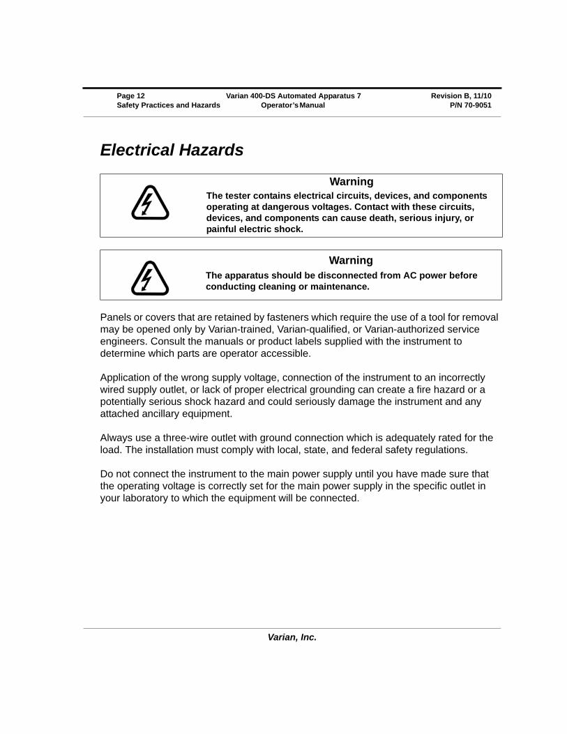
Electrical Hazards
Panels or covers that are retained by fasteners which require the use of a tool for removal may be opened only by Varian-trained, Varian-qualified, or Varian-authorized service engineers. Consult the manuals or product labels supplied with the instrument to determine which parts are operator accessible.
Application of the wrong supply voltage, connection of the instrument to an incorrectly wired supply outlet, or lack of proper electrical grounding can create a fire hazard or a potentially serious shock hazard and could seriously damage the instrument and any attached ancillary equipment.
Always use a three-wire outlet with ground connection which is adequately rated for the load. The installation must comply with local, state, and federal safety regulations.
Do not connect the instrument to the main power supply until you have made sure that the operating voltage is correctly set for the main power supply in the specific outlet in your laboratory to which the equipment will be connected.
WarningThe tester contains electrical circuits, devices, and components operating at dangerous voltages. Contact with these circuits, devices, and components can cause death, serious injury, or painful electric shock.
WarningThe apparatus should be disconnected from AC power before conducting cleaning or maintenance.
Varian, Inc.
Revision B, 11/10 Varian 400-DS Automated Apparatus 7 Page 13P/N 70-9051 Operator’s Manual Safety Practices and Hazards
Reciprocation Hazard
The Varian 400-DS Automated Apparatus 7 contains a magnetic plate that reciprocates up and down during operation. Trapping an appendage between the evaporation cover and this plate could cause injury.
Other
Other specific warnings and cautions appear in the manuals where appropriate. These notifications detail the specific hazard, describe how to avoid it, and specify the possible consequences of not heeding the warning or caution.
Warning
A ‘Warning’ message appears in the manual when failure to observe instructions or precautions could result in death or injury. Symbols depicting the nature of the specific hazard are also placed alongside warnings.
These symbols may be used on warning labels attached to the instrument. When you see one of these symbols you must refer to the relevant operation or service manual for the correct procedure referred to by that warning label.
Varian, Inc.
Page 14 Varian 400-DS Automated Apparatus 7 Revision B, 11/10Safety Practices and Hazards Operator’s Manual P/N 70-9051
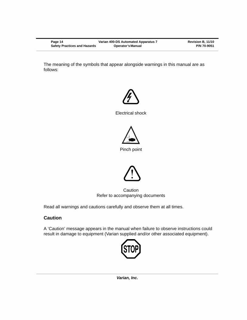
The meaning of the symbols that appear alongside warnings in this manual are as follows:
Read all warnings and cautions carefully and observe them at all times.
Caution
A ‘Caution’ message appears in the manual when failure to observe instructions could result in damage to equipment (Varian supplied and/or other associated equipment).
Electrical shock
Pinch point
CautionRefer to accompanying documents
Varian, Inc.
Revision B, 11/10 Varian 400-DS Automated Apparatus 7 Page 15P/N 70-9051 Operator’s Manual Safety Practices and Hazards
A ‘Note’ appears in the manual to give advice or information.
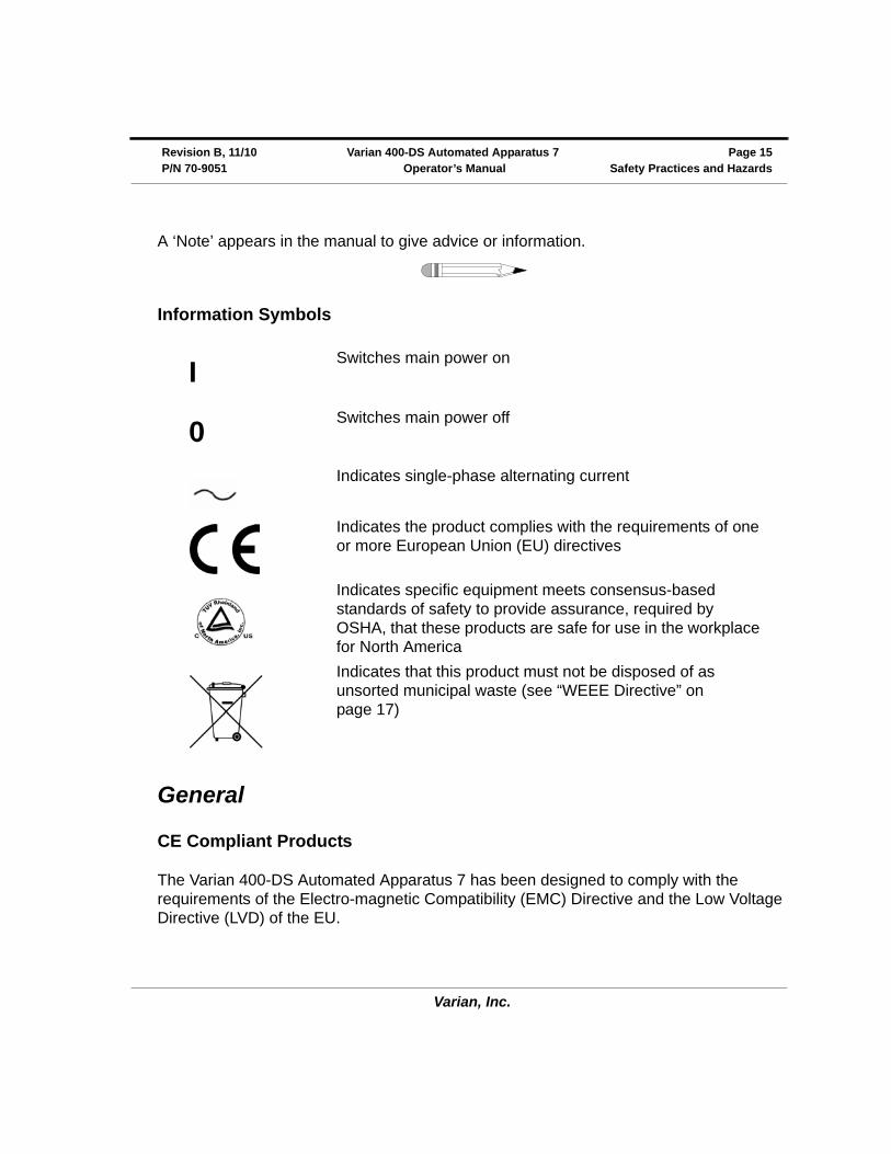
Information Symbols
General
CE Compliant Products
The Varian 400-DS Automated Apparatus 7 has been designed to comply with the requirements of the Electro-magnetic Compatibility (EMC) Directive and the Low Voltage Directive (LVD) of the EU.
I
Switches main power on
0
Switches main power off
Indicates single-phase alternating current
Indicates the product complies with the requirements of one or more European Union (EU) directives
Indicates specific equipment meets consensus-based standards of safety to provide assurance, required by OSHA, that these products are safe for use in the workplace for North America
Indicates that this product must not be disposed of as unsorted municipal waste (see “WEEE Directive” on page 17)
Varian, Inc.
Page 16 Varian 400-DS Automated Apparatus 7 Revision B, 11/10Safety Practices and Hazards Operator’s Manual P/N 70-9051
Varian, Inc. has confirmed that each product complies with the relevant directives by testing a prototype against the prescribed European Norm (EN) standards.
Proof that a product complies with the directives is indicated by:
• the CE marking appearing on the rear of the product.
• the documentation package that accompanies the product containing a copy of the declaration of conformity. This declaration is the legal declaration by Varian, Inc. that the product complies with the directives, and also shows the EN standards to which the product was tested to demonstrate compliance. The declaration of conformity is signed by the representative of the manufacturing plant.
cTUVus - U.S. and Canadian Product Approvals
The Varian 400-DS Automated Apparatus 7 has been designed to comply with North American safety requirements.
This product has been tested and certified for the North American market by TUV Rheinland of North America, Inc.. The TUVus mark signifies that this product has been tested to U.S. standards and certified for the U.S. market. The cTUV mark signifies that this product has been tested to Canadian standards and certified for the Canadian market. When the two marks are coupled, the cTUVus mark signifies that this product has been tested to standards and certified for both markets.

Varian, Inc.
Revision B, 11/10 Varian 400-DS Automated Apparatus 7 Page 17P/N 70-9051 Operator’s Manual Safety Practices and Hazards
WEEE Directive
All Varian products that are subject to the WEEE directive shipped after August 13, 2005 are compliant with the WEEE marking requirements. Such products are marked with the “crossed out wheelie bin” WEEE symbol shown on page 15 in accordance with European Standard EN 50419.
This symbol on the product or on its packaging indicates that this product must not be disposed of as unsorted municipal waste. The separate collection and recycling of your waste equipment at the time of disposal will help to conserve natural resources and ensure that it is recycled in a manner that protects human health and the environment.
For more information on collection, reuse, and recycling systems, please contact your local/regional waste administration, your local distributor, or Varian, Inc.

Varian, Inc.
Page 18 Varian 400-DS Automated Apparatus 7 Revision B, 11/10Safety Practices and Hazards Operator’s Manual P/N 70-9051
This page was intentionally left blank, except for this message.

Varian, Inc.
Chapter 1 Introduction
The patented Varian 400-DS Automated Apparatus 7 is ideal for extended-release products or any dosage form requiring release profiling at multiple pH levels. The 13 test samples traverse the two rows of corresponding cells filled with media. The Varian 400-DS Automated Apparatus 7 fills and dispenses media automatically, without operator intervention. A report can be generated to provide hard-copy documentation of the testing progress and conditions.
All parameters are controlled via the PC. Up to 4 units can be pre-programmed to withdraw samples at designated timepoints. Samples can be collected in pre-capped HPLC vials for direct transfer to an HPLC system. Septa are pierced using the exclusive needle manifold, which lowers and raises at each sample point. Sample trays are available in 1.5 mL and 4 mL sizes.
CautionPanels or covers that are retained by fasteners which require the use of a tool for removal may be opened only by Varian-trained, Varian-qualified, or Varian-authorized service engineers.
Varian, Inc.
Page 12 Varian 400-DS Automated Apparatus 7 Revision B, 11/10Introduction Operator’s Manual P/N 70-9051
Conventions Used in this Manual
• Items you are asked to press are in bold. For example, “press H on the keypad”.
• Key sequences you are asked to press appear like this: MENU > 0 > 8.
USP Physical Parameters
In addition to the apparatus suitability test, you must monitor several physical parameters, such as stroke distance, dip speed, and temperature. A Certificate of Compliance is included with your Varian 400-DS. Contact the Laboratory Services Department for more information on USP physical parameters.
NoteRemember to return the warranty card supplied with this manual. Completing and returning the card ensures your right to protection under the terms and conditions of your warranty. It also enables us to better assist you in the event of any problems. Additionally, it guarantees you will be informed of any issues that arise concerning your equipment, such as upgrades, retrofits, or regulatory changes.
Varian, Inc.
Revision B, 11/10 Varian 400-DS Automated Apparatus 7 Page 13P/N 70-9051 Operator’s Manual Introduction
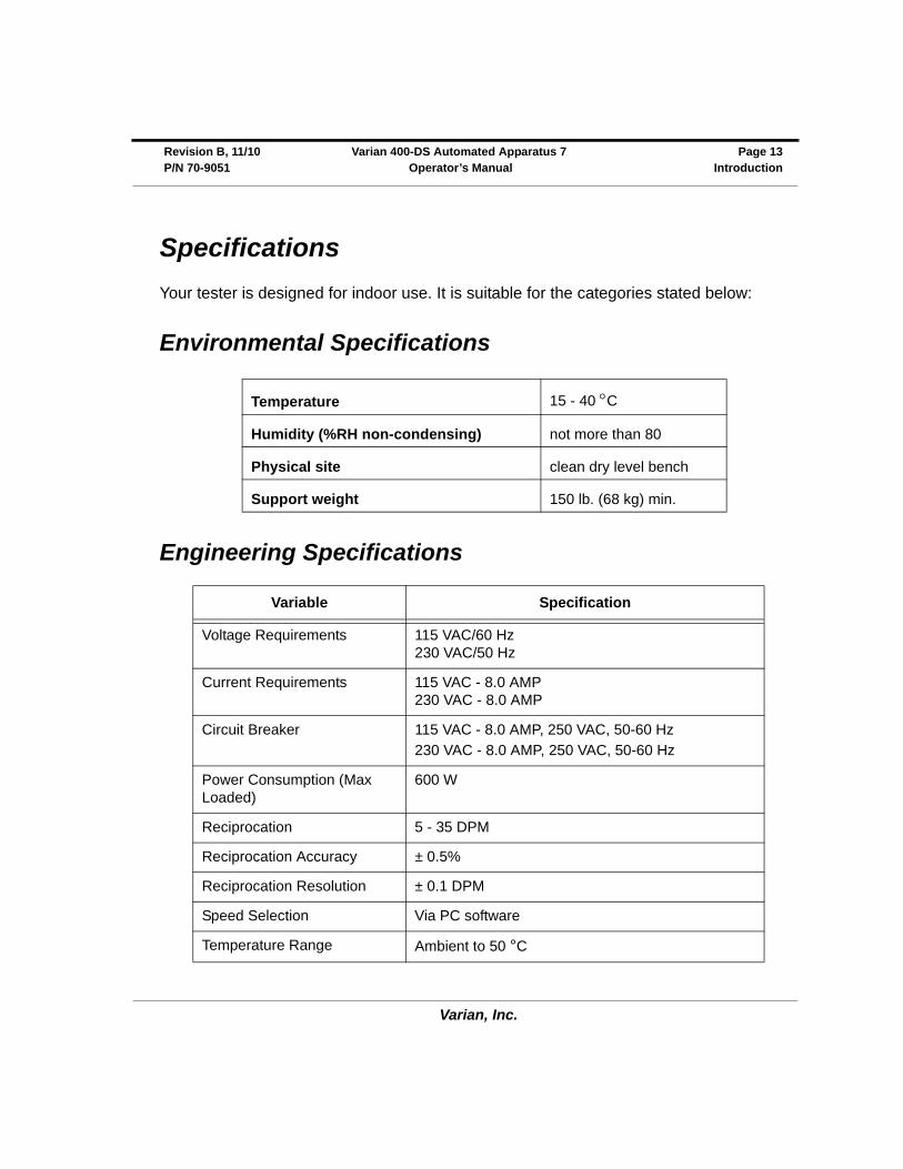
Specifications
Your tester is designed for indoor use. It is suitable for the categories stated below:
Environmental Specifications
Engineering Specifications
Temperature 15 - 40 C
Humidity (%RH non-condensing) not more than 80
Physical site clean dry level bench
Support weight 150 lb. (68 kg) min.
Variable Specification
Voltage Requirements 115 VAC/60 Hz230 VAC/50 Hz
Current Requirements 115 VAC - 8.0 AMP230 VAC - 8.0 AMP
Circuit Breaker 115 VAC - 8.0 AMP, 250 VAC, 50-60 Hz
230 VAC - 8.0 AMP, 250 VAC, 50-60 Hz
Power Consumption (Max Loaded)
600 W
Reciprocation 5 - 35 DPM
Reciprocation Accuracy ± 0.5%
Reciprocation Resolution ± 0.1 DPM
Speed Selection Via PC software
Temperature Range Ambient to 50 °C
Varian, Inc.
Page 14 Varian 400-DS Automated Apparatus 7 Revision B, 11/10Introduction Operator’s Manual P/N 70-9051
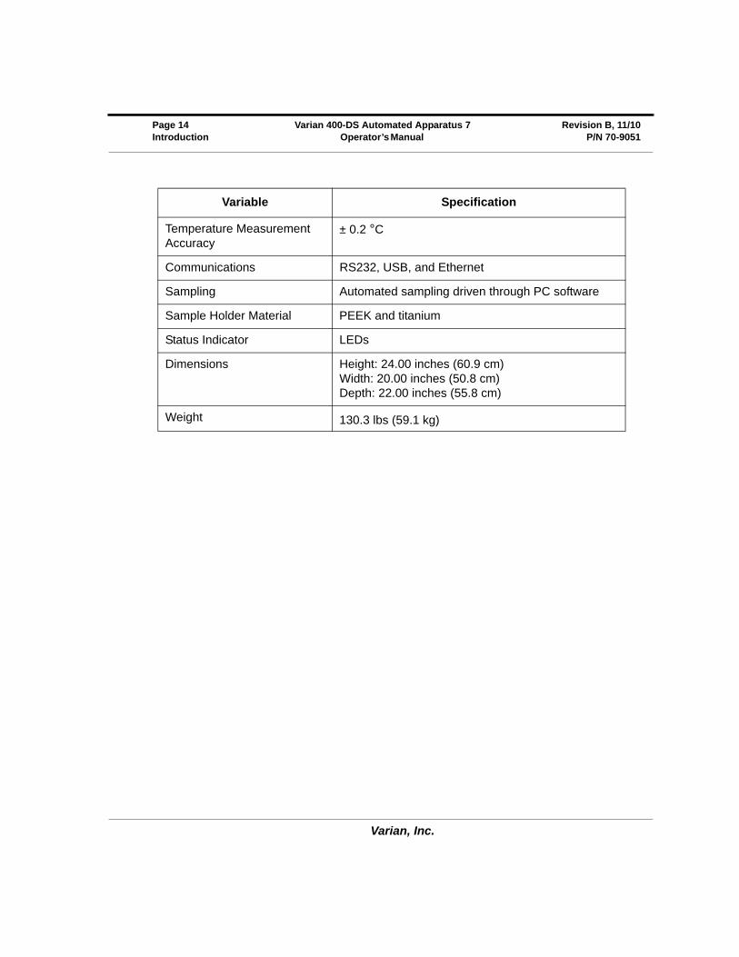
Temperature Measurement Accuracy
± 0.2 °C
Communications RS232, USB, and Ethernet
Sampling Automated sampling driven through PC software
Sample Holder Material PEEK and titanium
Status Indicator LEDs
Dimensions Height: 24.00 inches (60.9 cm)Width: 20.00 inches (50.8 cm)Depth: 22.00 inches (55.8 cm)
Weight 130.3 lbs (59.1 kg)
Variable Specification
Varian, Inc.
Revision B, 11/10 Varian 400-DS Automated Apparatus 7 Page 15P/N 70-9051 Operator’s Manual Introduction
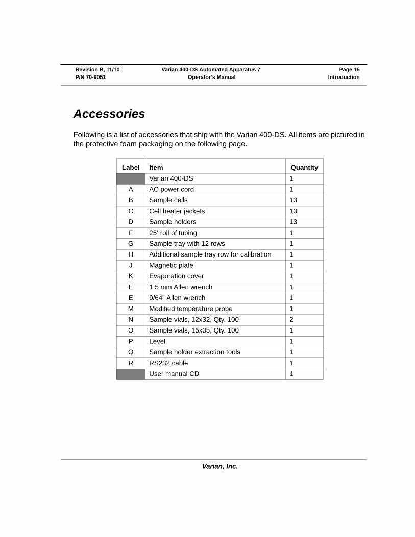
Accessories
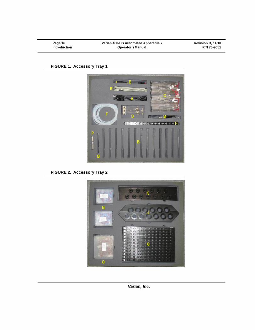
Following is a list of accessories that ship with the Varian 400-DS. All items are pictured in the protective foam packaging on the following page.
Label Item Quantity
Varian 400-DS 1
A AC power cord 1
B Sample cells 13
C Cell heater jackets 13
D Sample holders 13
F 25’ roll of tubing 1
G Sample tray with 12 rows 1
H Additional sample tray row for calibration 1
J Magnetic plate 1
K Evaporation cover 1
E 1.5 mm Allen wrench 1
E 9/64” Allen wrench 1
M Modified temperature probe 1
N Sample vials, 12x32, Qty. 100 2
O Sample vials, 15x35, Qty. 100 1
P Level 1
Q Sample holder extraction tools 1
R RS232 cable 1
User manual CD 1
Varian, Inc.
Page 16 Varian 400-DS Automated Apparatus 7 Revision B, 11/10Introduction Operator’s Manual P/N 70-9051
FIGURE 1. Accessory Tray 1
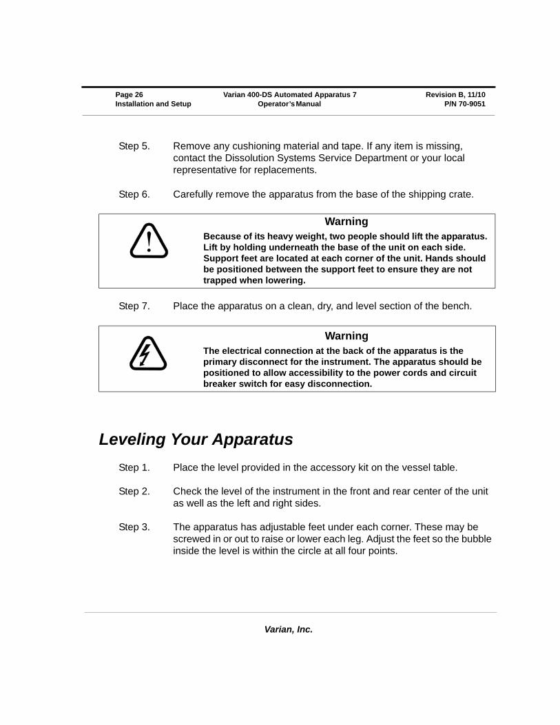
FIGURE 2. Accessory Tray 2

Varian, Inc.
Chapter 3 Installation and Setup
Unpacking Your Equipment
The Varian 400-DS is shipped in one crate. The crate contains the apparatus and accessories.
Step 1. Open the crate and check the contents for damage, which may have occurred during shipping. Shipping damage rarely occurs, but if it does contact both the carrier who delivered the instruments and the Dissolution Systems Service Department. Though claims for damage should be filed with the carrier, we can help you file a claim.
Step 2. Remove the top of the crate.
Step 3. Remove one side of the crate and lift the accessories box out of the crate.
Step 4. Disassemble the other three sides of the crate.
Varian, Inc.
Page 26 Varian 400-DS Automated Apparatus 7 Revision B, 11/10Installation and Setup Operator’s Manual P/N 70-9051
Step 5. Remove any cushioning material and tape. If any item is missing, contact the Dissolution Systems Service Department or your local representative for replacements.
Step 6. Carefully remove the apparatus from the base of the shipping crate.
Step 7. Place the apparatus on a clean, dry, and level section of the bench.
Leveling Your Apparatus
Step 1. Place the level provided in the accessory kit on the vessel table.
Step 2. Check the level of the instrument in the front and rear center of the unit as well as the left and right sides.
Step 3. The apparatus has adjustable feet under each corner. These may be screwed in or out to raise or lower each leg. Adjust the feet so the bubble inside the level is within the circle at all four points.
WarningBecause of its heavy weight, two people should lift the apparatus. Lift by holding underneath the base of the unit on each side. Support feet are located at each corner of the unit. Hands should be positioned between the support feet to ensure they are not trapped when lowering.
WarningThe electrical connection at the back of the apparatus is the primary disconnect for the instrument. The apparatus should be positioned to allow accessibility to the power cords and circuit breaker switch for easy disconnection.
Varian, Inc.
Revision B, 11/10 Varian 400-DS Automated Apparatus 7 Page 27P/N 70-9051 Operator’s Manual Installation and Setup
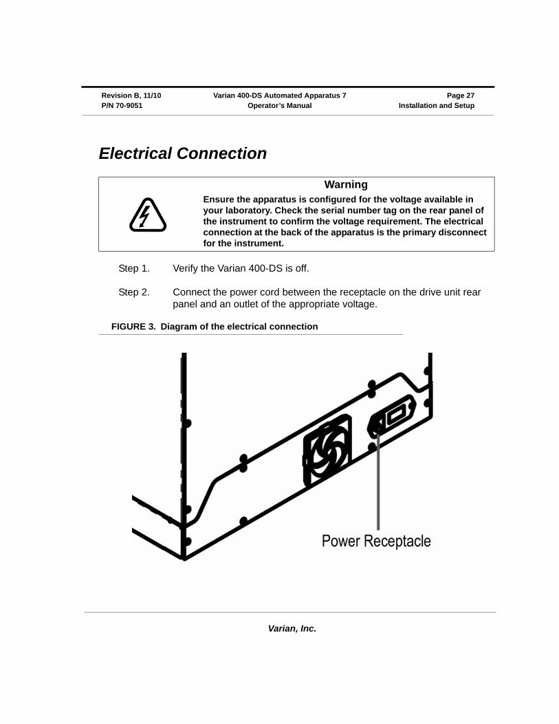
Electrical Connection
Step 1. Verify the Varian 400-DS is off.
Step 2. Connect the power cord between the receptacle on the drive unit rear panel and an outlet of the appropriate voltage.
FIGURE 3. Diagram of the electrical connection
WarningEnsure the apparatus is configured for the voltage available in your laboratory. Check the serial number tag on the rear panel of the instrument to confirm the voltage requirement. The electrical connection at the back of the apparatus is the primary disconnect for the instrument.
Varian, Inc.
Page 28 Varian 400-DS Automated Apparatus 7 Revision B, 11/10Installation and Setup Operator’s Manual P/N 70-9051
Setting up Your PC
The 400-DS Workstation software requires Microsoft Windows® 2000 or Windows XP® to be installed on your computer. For instructions on installing the operating system, refer to the documentation supplied with Windows®.
If the PC is not equipped with a standard serial port, a USB-to-serial converter must be purchased.
If Varian is installing the 400-DS Workstation software for you, note that the installation of a Windows® operating system is not included as part of the standard instrument installation.
The monitor, keyboard, mouse, and printer/plotter are connected to the PC via cables which plug into the back of the PC. Consult your monitor and printer manuals for details of their individual cabling requirements.
Minimum PC Configuration
• Windows® 2000 SP6 or Windows XP® SP1
• 256 MB RAM
• 1024 x 768 pixel display resolution
• 10 GB free hard disk drive space • 2x USB port (optional)
Varian, Inc.
Revision B, 11/10 Varian 400-DS Automated Apparatus 7 Page 29P/N 70-9051 Operator’s Manual Installation and Setup
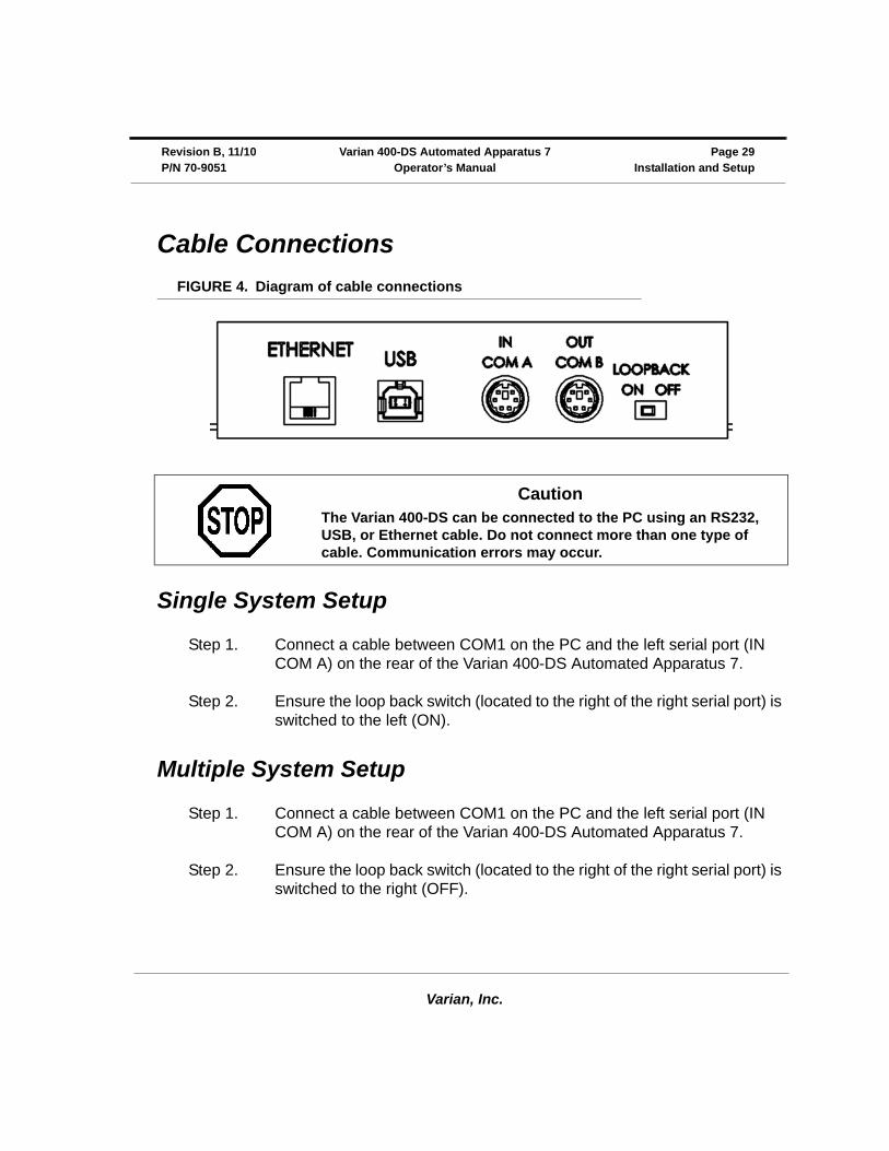
Cable Connections
FIGURE 4. Diagram of cable connections
Single System Setup
Step 1. Connect a cable between COM1 on the PC and the left serial port (IN COM A) on the rear of the Varian 400-DS Automated Apparatus 7.
Step 2. Ensure the loop back switch (located to the right of the right serial port) is switched to the left (ON).
Multiple System Setup
Step 1. Connect a cable between COM1 on the PC and the left serial port (IN COM A) on the rear of the Varian 400-DS Automated Apparatus 7.
Step 2. Ensure the loop back switch (located to the right of the right serial port) is switched to the right (OFF).
CautionThe Varian 400-DS can be connected to the PC using an RS232, USB, or Ethernet cable. Do not connect more than one type of cable. Communication errors may occur.
Varian, Inc.
Page 30 Varian 400-DS Automated Apparatus 7 Revision B, 11/10Installation and Setup Operator’s Manual P/N 70-9051
Step 3. Connect a 6-pin mini-DIN cable between the right serial port (OUT COM B) of the first apparatus and the left serial port of the second apparatus.
Step 4. If this is the final Varian 400-DS Automated Apparatus 7 in the series, ensure the loop back switch (located to the right of the right serial port) is switched to the left (ON).
If this is not the final Varian 400-DS Automated Apparatus 7 in the series, ensure the loop back switch (located to the right of the right serial port) is switched to the right (OFF).
Step 5. Repeat steps 3 and 4 for each additional apparatus.
Setting Up the Varian 400-DS
Step 1. Locate the 1.5 mm Allen wrench to install the sample heater jackets.
Step 2. Install the first cell heater by placing it over the thermistor at the desired cell position of the Varian 400-DS.
Step 3. While holding the jacket in place, use the Allen wrench to tighten the screw.
Step 4. Insert the 2-pin plug for the heater in the appropriate location on the sample heater jacket.
Step 5. Repeat steps 2 - 4 to install the sample heater jackets for the remaining cell positions.
Step 6. Install the magnetic plate on the reciprocation guide rod, which is the shorter rod in the middle of the 3 rods on the Varian 400-DS.
Step 7. Tighten the bolt on each end of the magnetic plate using the 9/64" Allen wrench.
Varian, Inc.
Revision B, 11/10 Varian 400-DS Automated Apparatus 7 Page 31P/N 70-9051 Operator’s Manual Installation and Setup
Step 8. Install the guide rod stabilizers on top of the magnetic plate using the two longer guide rods for alignment.
Step 9. Tighten the two bolts on each stabilizer plate using the 9/64" Allen wrench.
Step 10. Locate the sample cells and sample holders provided with your instrument.
Step 11. Remove the sample cells and holders from the packing material to ensure no damage occurred during shipment.
Step 12. To install a sample cell in the heater jacket, slide one end through the magnetic lift plate.
Step 13. Use the finger tabs on the heater jacket to spread it open.
Step 14. Continue to lower the sample cell until it is secure and completely covers the bottom cell seal.
Step 15. With the magnet at the top, insert the sample holder into the sample cell.
Step 16. Repeat steps 12 - 15 to install the remaining sample cells and holders.
Step 17. Replace the evaporation cover and tighten the two thumb screws.
CautionBe careful when sliding the sample cells over the O-ring seals as damage can occur. Ensure the cell and seal are properly aligned before applying pressure.

Varian, Inc.
Page 32 Varian 400-DS Automated Apparatus 7 Revision B, 11/10Installation and Setup Operator’s Manual P/N 70-9051
Initial Power Up
Step 1. Ensure the circuit breaker on the rear of the instrument is on.
Step 2. Turn on the power switch on the front panel and ensure the integrated red LED illuminates.
Step 3. Repeat steps 1 and 2 for each Varian 400-DS Automated Apparatus 7.
Step 4. Turn on the PC, monitor, and printer. Verify the PC power light illuminates and the Microsoft ® Windows®XP or Windows® 2000 initializes.
Software Installation
To install the software, complete the following steps:
Step 1. Install the 400-DS Workstation CD and access the files.
Step 2. Execute the file setup.exe and follow the on-screen prompts.
Step 3. When asked if you want to install the Microsoft .Net Framework V1.1, you must click Yes.
Step 4. After the installation has successfully completed, install the license dongle by plugging it into an open USB port.
NoteTo complete the installation of the 400-DS Workstation software, you must log on to the PC as an administrator. Attaching the Database and Local Security Policy are included as part of the software installation procedures. The CD contains all of the requirements for an installation.

Varian, Inc.
Revision B, 11/10 Varian 400-DS Automated Apparatus 7 Page 33P/N 70-9051 Operator’s Manual Installation and Setup
FIGURE 5. License dongle
Attaching the Database
Once the basic installation is complete, complete the following steps to attach the database files:
Step 1. Click Start > All Programs > Varian > Dissolution > MSDE Manager. The MSDE Manager screen displays.
NoteThis section is only required when upgrading an existing installation.
Varian, Inc.
Page 34 Varian 400-DS Automated Apparatus 7 Revision B, 11/10Installation and Setup Operator’s Manual P/N 70-9051
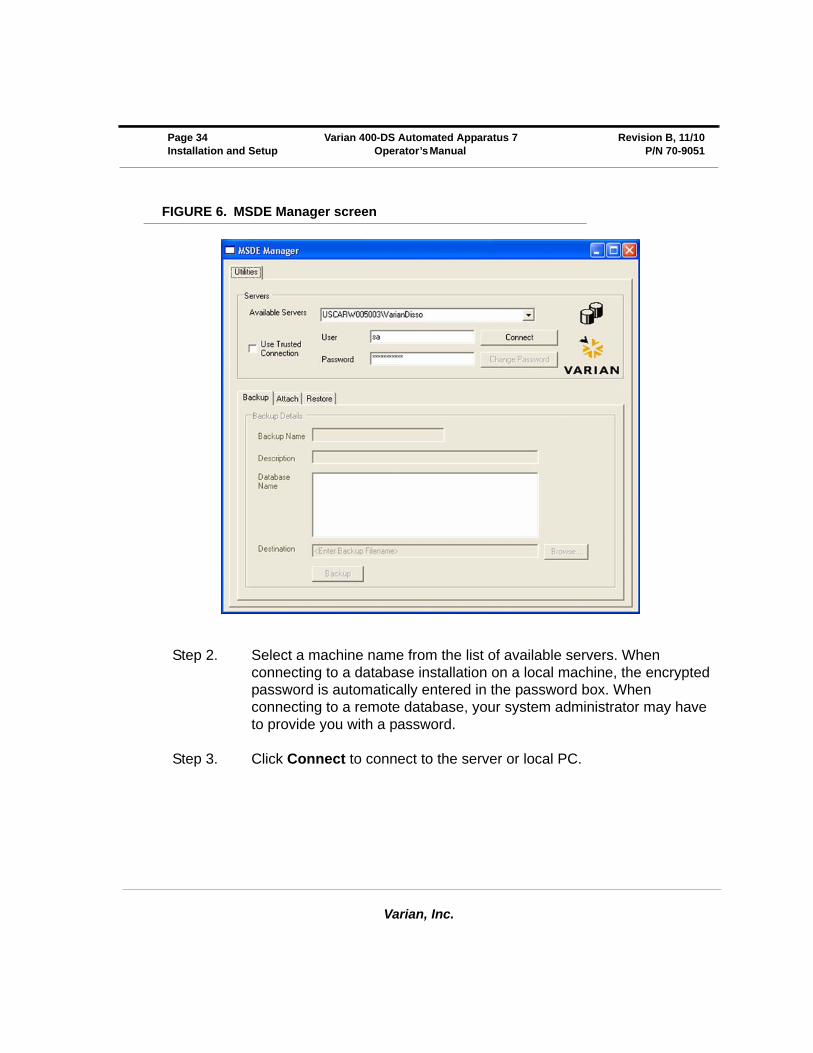
FIGURE 6. MSDE Manager screen
Step 2. Select a machine name from the list of available servers. When connecting to a database installation on a local machine, the encrypted password is automatically entered in the password box. When connecting to a remote database, your system administrator may have to provide you with a password.
Step 3. Click Connect to connect to the server or local PC.
Varian, Inc.
Revision B, 11/10 Varian 400-DS Automated Apparatus 7 Page 35P/N 70-9051 Operator’s Manual Installation and Setup
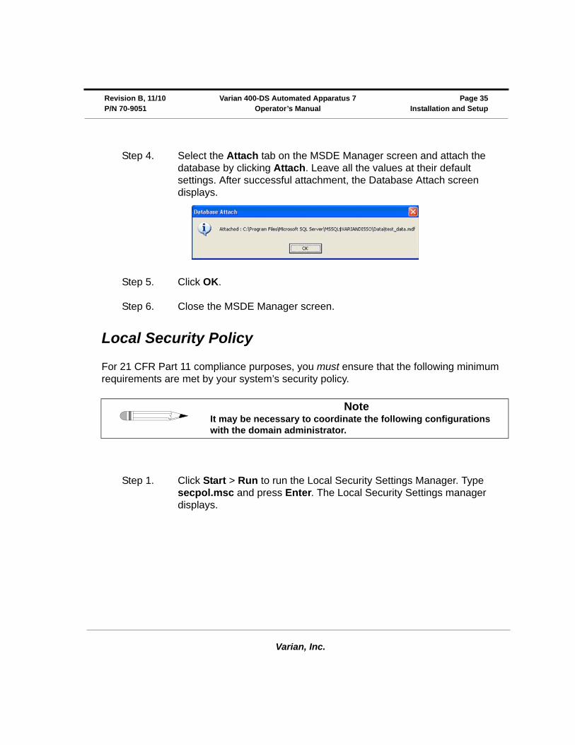
Step 4. Select the Attach tab on the MSDE Manager screen and attach the database by clicking Attach. Leave all the values at their default settings. After successful attachment, the Database Attach screen displays.
Step 5. Click OK.
Step 6. Close the MSDE Manager screen.
Local Security Policy
For 21 CFR Part 11 compliance purposes, you must ensure that the following minimum requirements are met by your system’s security policy.
Step 1. Click Start > Run to run the Local Security Settings Manager. Type secpol.msc and press Enter. The Local Security Settings manager displays.
NoteIt may be necessary to coordinate the following configurations with the domain administrator.
Varian, Inc.
Page 36 Varian 400-DS Automated Apparatus 7 Revision B, 11/10Installation and Setup Operator’s Manual P/N 70-9051
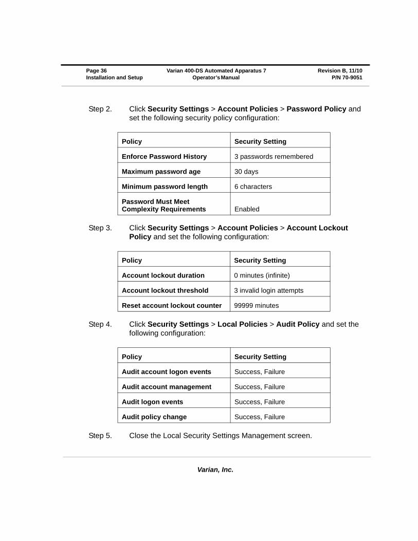
Step 2. Click Security Settings > Account Policies > Password Policy and set the following security policy configuration:
Step 3. Click Security Settings > Account Policies > Account Lockout Policy and set the following configuration:
Step 4. Click Security Settings > Local Policies > Audit Policy and set the following configuration:
Step 5. Close the Local Security Settings Management screen.
Policy Security Setting
Enforce Password History 3 passwords remembered
Maximum password age 30 days
Minimum password length 6 characters
Password Must Meet Complexity Requirements Enabled
Policy Security Setting
Account lockout duration 0 minutes (infinite)
Account lockout threshold 3 invalid login attempts
Reset account lockout counter 99999 minutes
Policy Security Setting
Audit account logon events Success, Failure
Audit account management Success, Failure
Audit logon events Success, Failure
Audit policy change Success, Failure
Varian, Inc.
Revision B, 11/10 Varian 400-DS Automated Apparatus 7 Page 37P/N 70-9051 Operator’s Manual Installation and Setup
E-mail Notification Configuration (Optional)
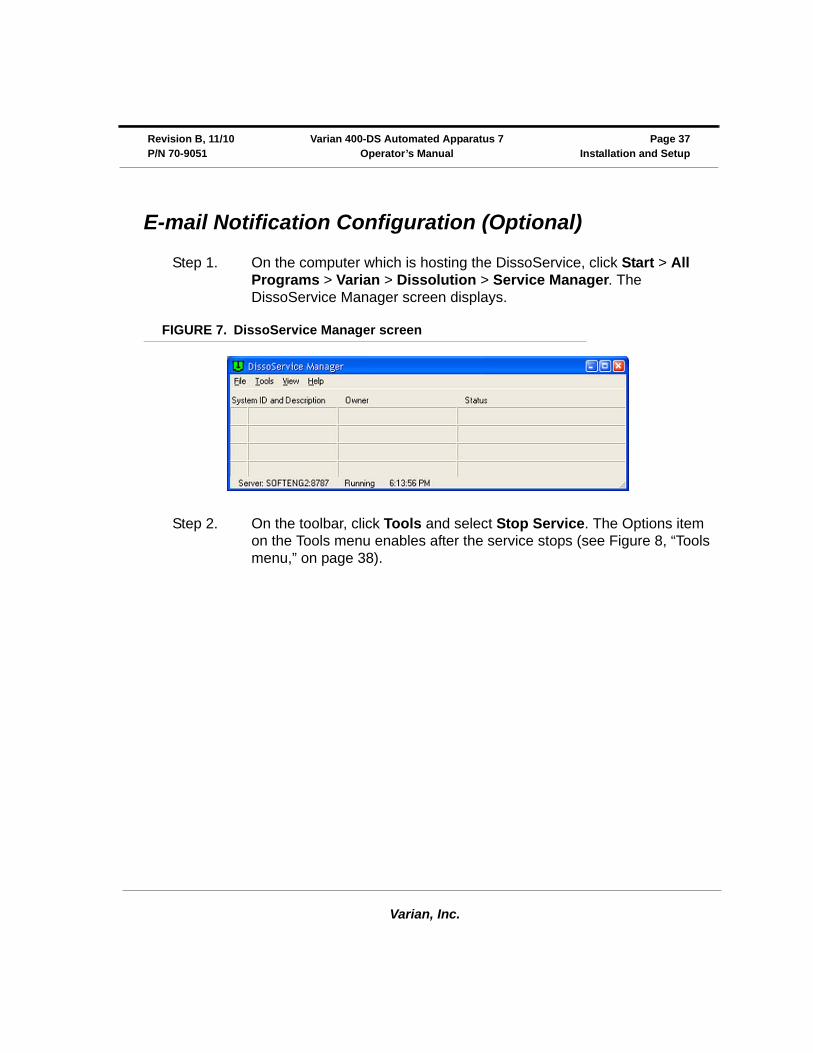
Step 1. On the computer which is hosting the DissoService, click Start > All Programs > Varian > Dissolution > Service Manager. The DissoService Manager screen displays.
FIGURE 7. DissoService Manager screen
Step 2. On the toolbar, click Tools and select Stop Service. The Options item on the Tools menu enables after the service stops (see Figure 8, “Tools menu,” on page 38).
Varian, Inc.
Page 38 Varian 400-DS Automated Apparatus 7 Revision B, 11/10Installation and Setup Operator’s Manual P/N 70-9051
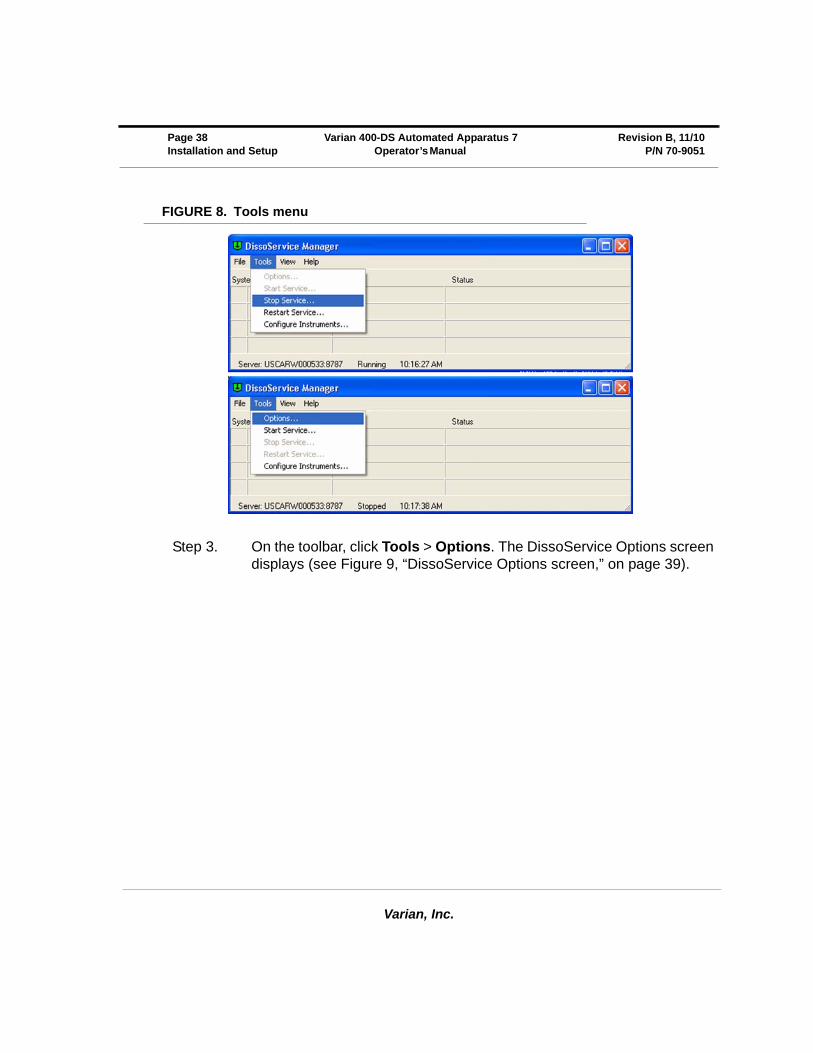
FIGURE 8. Tools menu
Step 3. On the toolbar, click Tools > Options. The DissoService Options screen displays (see Figure 9, “DissoService Options screen,” on page 39).
Varian, Inc.
Revision B, 11/10 Varian 400-DS Automated Apparatus 7 Page 39P/N 70-9051 Operator’s Manual Installation and Setup
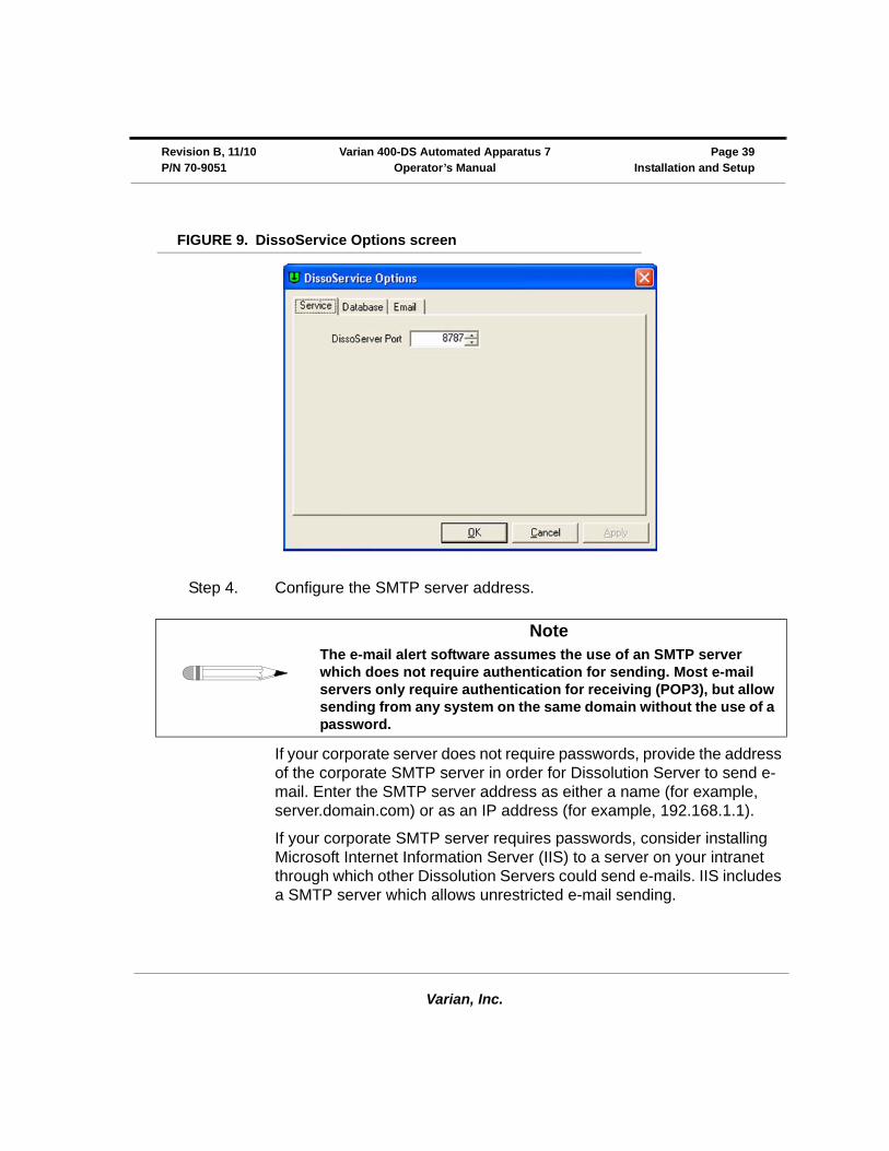
FIGURE 9. DissoService Options screen
Step 4. Configure the SMTP server address.
If your corporate server does not require passwords, provide the address of the corporate SMTP server in order for Dissolution Server to send e-mail. Enter the SMTP server address as either a name (for example, server.domain.com) or as an IP address (for example, 192.168.1.1).
If your corporate SMTP server requires passwords, consider installing Microsoft Internet Information Server (IIS) to a server on your intranet through which other Dissolution Servers could send e-mails. IIS includes a SMTP server which allows unrestricted e-mail sending.
NoteThe e-mail alert software assumes the use of an SMTP server which does not require authentication for sending. Most e-mail servers only require authentication for receiving (POP3), but allow sending from any system on the same domain without the use of a password.
Varian, Inc.
Page 40 Varian 400-DS Automated Apparatus 7 Revision B, 11/10Installation and Setup Operator’s Manual P/N 70-9051
Step 5. Once you have configured the SMTP server address, click OK to save the settings.
Step 6. On the toolbar, click Tools and select Start Service.
Starting 400-DS Workstation
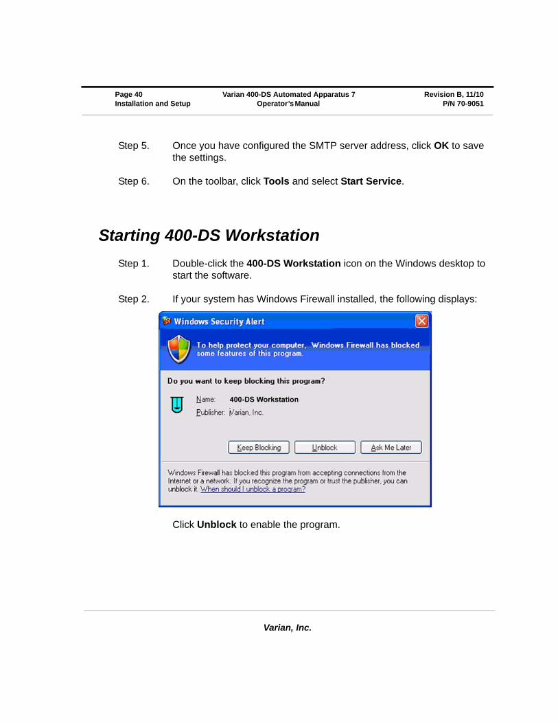
Step 1. Double-click the 400-DS Workstation icon on the Windows desktop to start the software.
Step 2. If your system has Windows Firewall installed, the following displays:
Click Unblock to enable the program.
Varian, Inc.
Revision B, 11/10 Varian 400-DS Automated Apparatus 7 Page 41P/N 70-9051 Operator’s Manual Installation and Setup
Dissolution Server Selection
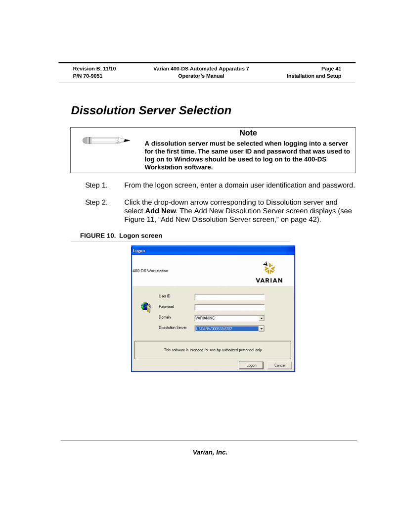
Step 1. From the logon screen, enter a domain user identification and password.
Step 2. Click the drop-down arrow corresponding to Dissolution server and select Add New. The Add New Dissolution Server screen displays (see Figure 11, “Add New Dissolution Server screen,” on page 42).
FIGURE 10. Logon screen
NoteA dissolution server must be selected when logging into a server for the first time. The same user ID and password that was used to log on to Windows should be used to log on to the 400-DS Workstation software.
Varian, Inc.
Page 42 Varian 400-DS Automated Apparatus 7 Revision B, 11/10Installation and Setup Operator’s Manual P/N 70-9051
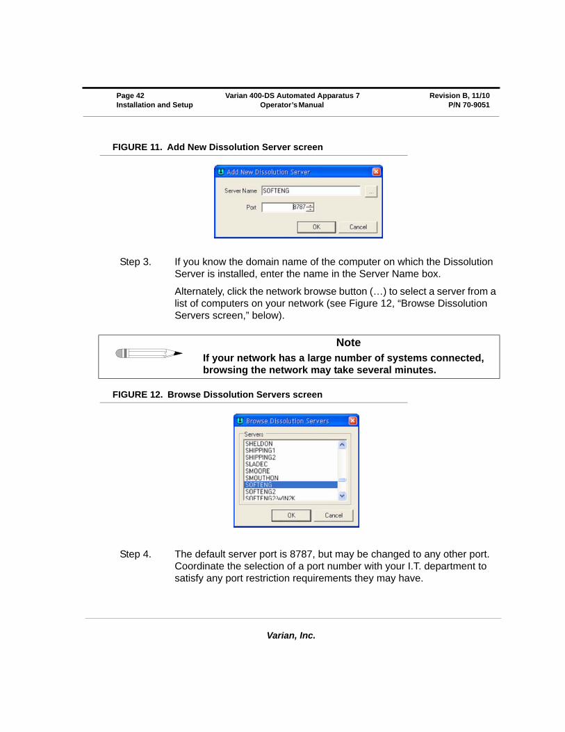
FIGURE 11. Add New Dissolution Server screen
Step 3. If you know the domain name of the computer on which the Dissolution Server is installed, enter the name in the Server Name box.
Alternately, click the network browse button (…) to select a server from a list of computers on your network (see Figure 12, “Browse Dissolution Servers screen,” below).
FIGURE 12. Browse Dissolution Servers screen
Step 4. The default server port is 8787, but may be changed to any other port. Coordinate the selection of a port number with your I.T. department to satisfy any port restriction requirements they may have.
NoteIf your network has a large number of systems connected, browsing the network may take several minutes.
Varian, Inc.
Revision B, 11/10 Varian 400-DS Automated Apparatus 7 Page 43P/N 70-9051 Operator’s Manual Installation and Setup
Step 5. Click OK.
Step 6. Click Logon on the Logon screen.
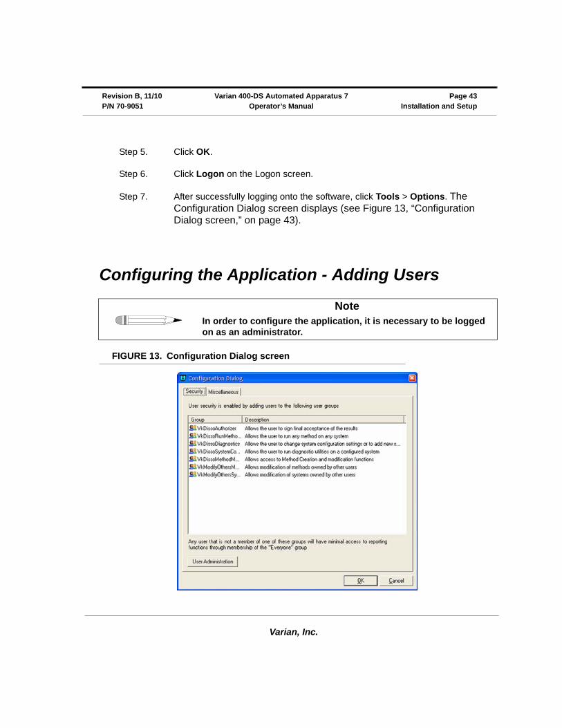
Step 7. After successfully logging onto the software, click Tools > Options. The Configuration Dialog screen displays (see Figure 13, “Configuration Dialog screen,” on page 43).
Configuring the Application - Adding Users
FIGURE 13. Configuration Dialog screen
NoteIn order to configure the application, it is necessary to be logged on as an administrator.
Varian, Inc.
Page 44 Varian 400-DS Automated Apparatus 7 Revision B, 11/10Installation and Setup Operator’s Manual P/N 70-9051
Step 1. To add a user to a group, select the Security tab on the Configuration Dialog screen.
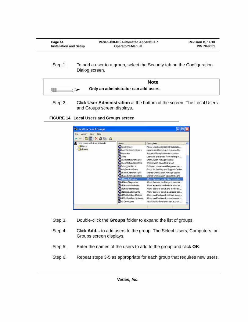
Step 2. Click User Administration at the bottom of the screen. The Local Users and Groups screen displays.
FIGURE 14. Local Users and Groups screen
Step 3. Double-click the Groups folder to expand the list of groups.
Step 4. Click Add... to add users to the group. The Select Users, Computers, or Groups screen displays.
Step 5. Enter the names of the users to add to the group and click OK.
Step 6. Repeat steps 3-5 as appropriate for each group that requires new users.
NoteOnly an administrator can add users.
Varian, Inc.
Revision B, 11/10 Varian 400-DS Automated Apparatus 7 Page 45P/N 70-9051 Operator’s Manual Installation and Setup
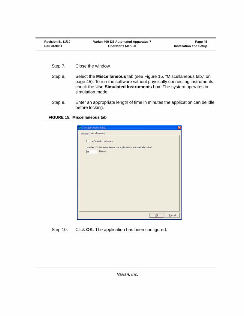
Step 7. Close the window.
Step 8. Select the Miscellaneous tab (see Figure 15, “Miscellaneous tab,” on page 45). To run the software without physically connecting instruments, check the Use Simulated Instruments box. The system operates in simulation mode.
Step 9. Enter an appropriate length of time in minutes the application can be idle before locking.
FIGURE 15. Miscellaneous tab
Step 10. Click OK. The application has been configured.
Varian, Inc.
Page 46 Varian 400-DS Automated Apparatus 7 Revision B, 11/10Installation and Setup Operator’s Manual P/N 70-9051
This page was intentionally left blank, except for this message.
Varian, Inc.
Chapter 4 Operation
Log on to the Varian 400-DS Workstation
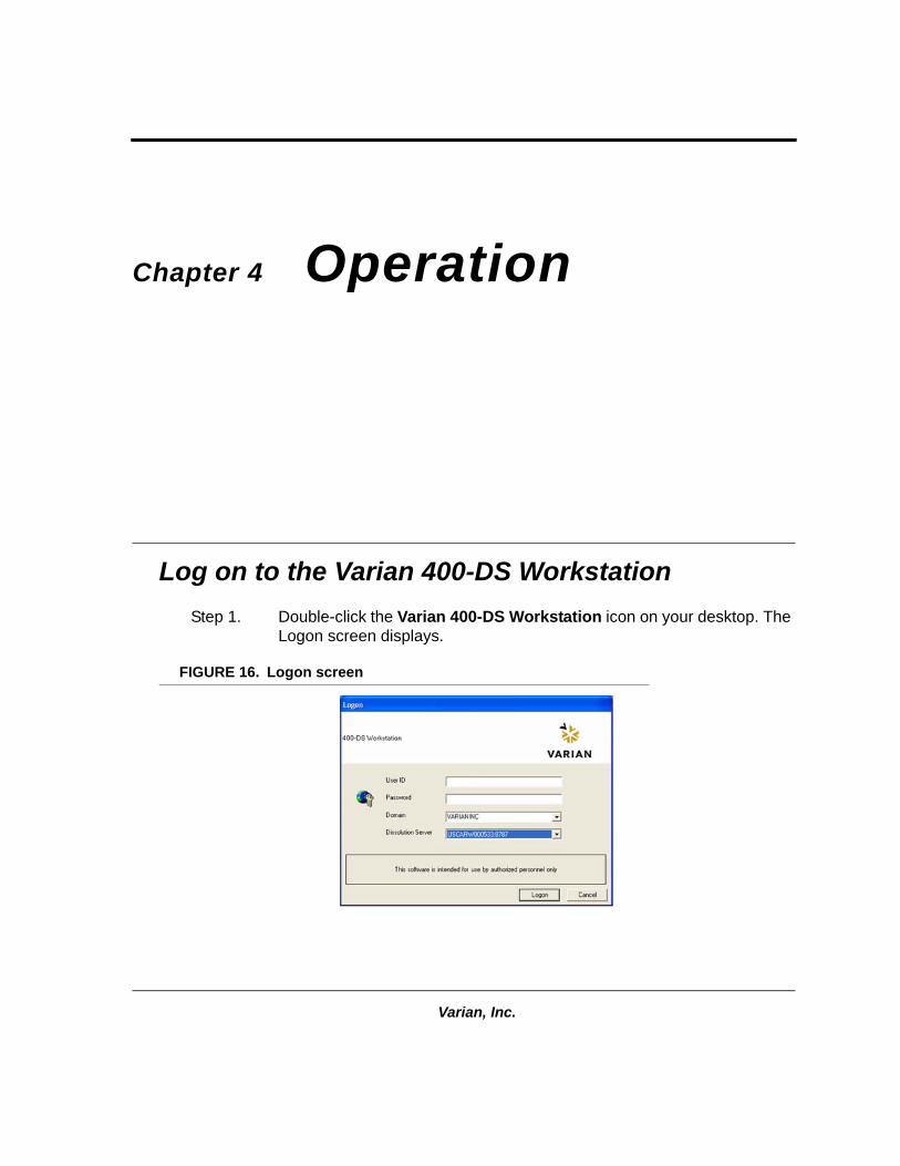
Step 1. Double-click the Varian 400-DS Workstation icon on your desktop. The Logon screen displays.
FIGURE 16. Logon screen
Varian, Inc.
Page 48 Varian 400-DS Automated Apparatus 7 Revision B, 11/10Operation Operator’s Manual P/N 70-9051
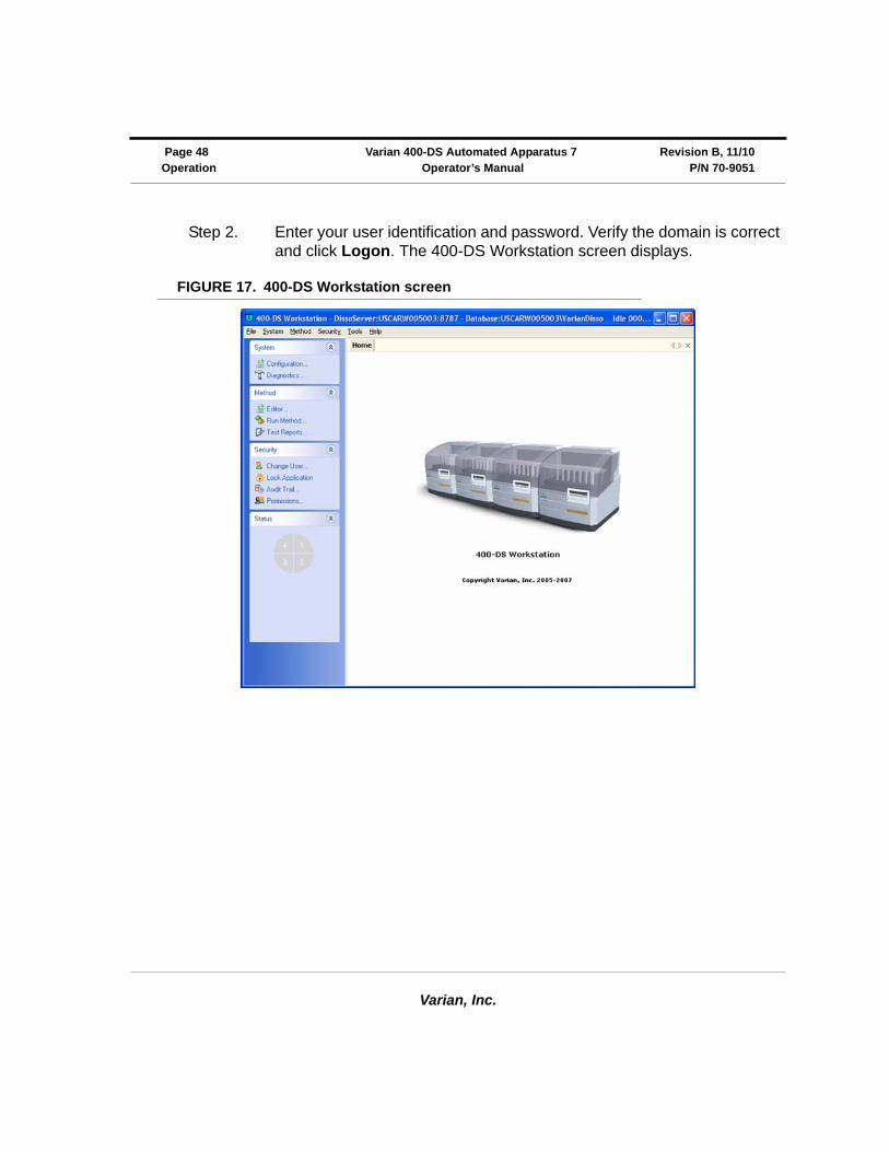
Step 2. Enter your user identification and password. Verify the domain is correct and click Logon. The 400-DS Workstation screen displays.
FIGURE 17. 400-DS Workstation screen
Varian, Inc.
Revision B, 11/10 Varian 400-DS Automated Apparatus 7 Page 49P/N 70-9051 Operator’s Manual Operation
Following is a description of the screen options listed on the navigation bar of the 400-DS Workstation screen:
Option Description
System Configuration Use this option to configure the system. See “Configuring Your System” on page 50.
Diagnostics Use this option to check the diagnostics of a dissolution apparatus or accessory within the system. See “Manual Control/Diagnostics” on page 64.
Method Editor Use this option to create a method, change or delete method parameters, run a report of the method setup, view the method audit trail, and verify the integrity of the method. See “Method Editor” on page 69.
Run Method Use this option to run a method. See “Running the Method” on page 82.
Test Reports Use this option to run a report of the completed method. See “Test Reports” on page 87.
Security Change User To change the user, click Change User. The Logon screen displays. Enter the appropriate user identification and password and click Logon.
Lock Application
To lock the 400-DS Workstation screen, click Lock Application. The 400-DS Workstation Locked screen displays. Click the lock or the link to unlock the screen. The Logon screen displays. Enter the appropriate user identification and password as applicable and click Logon.
Audit Trail Click Audit Trail. The Security Audit Trail screen displays. Click Show Report to display the report. Change the start date, end date, and/or user identification as desired and click Retrieve Records to change the parameters for the information displayed.
Permissions Use this option to view permissions assigned to the current user and the descriptions of the corresponding privileges.
Click Permissions. The User Group Membership screen displays.
Status Click one of the pie-shaped graphics under status to view the status of the corresponding dissolution system.
Varian, Inc.
Page 50 Varian 400-DS Automated Apparatus 7 Revision B, 11/10Operation Operator’s Manual P/N 70-9051
Configuring Your System
It is necessary to configure the components that will be used for automated sample collection. Systems can be added, modified, and removed from the database. All system configuration activity is recorded in the system audit log. The dissolution software allows the configuration of multiple systems. A maximum of four systems can be running methods at one time.
System configuration entails selecting the appropriate equipment and setting the communication and other physical properties of the system. Serial numbers are stored for each system to allow tracking of physical system changes.
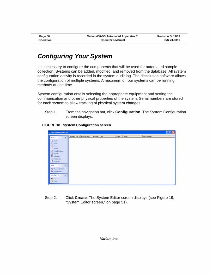
Step 1. From the navigation bar, click Configuration. The System Configuration screen displays.
FIGURE 18. System Configuration screen
Step 2. Click Create. The System Editor screen displays (see Figure 19, “System Editor screen,” on page 51).
Varian, Inc.
Revision B, 11/10 Varian 400-DS Automated Apparatus 7 Page 51P/N 70-9051 Operator’s Manual Operation
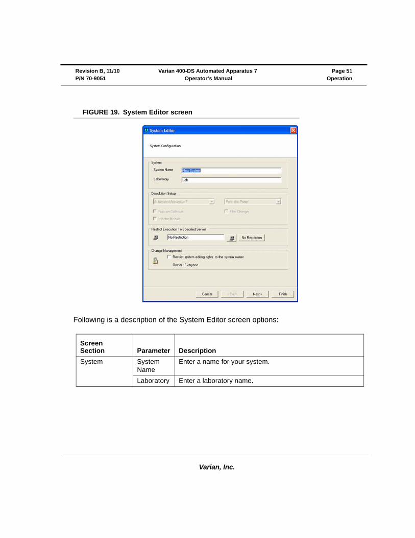
FIGURE 19. System Editor screen
Following is a description of the System Editor screen options:
Screen Section Parameter Description
System System Name
Enter a name for your system.
Laboratory Enter a laboratory name.
Varian, Inc.
Page 52 Varian 400-DS Automated Apparatus 7 Revision B, 11/10Operation Operator’s Manual P/N 70-9051
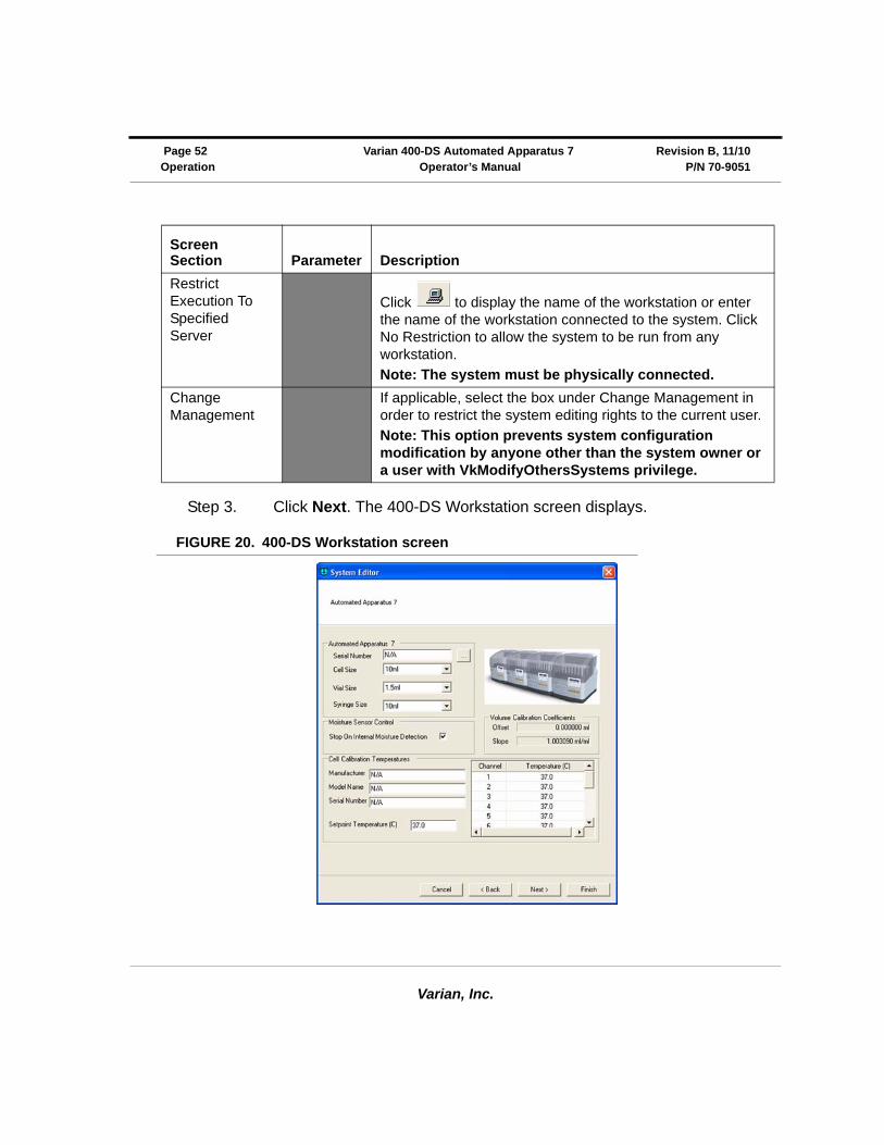
Step 3. Click Next. The 400-DS Workstation screen displays.
FIGURE 20. 400-DS Workstation screen
Restrict Execution To Specified Server
Click to display the name of the workstation or enter the name of the workstation connected to the system. Click No Restriction to allow the system to be run from any workstation.
Note: The system must be physically connected.
Change Management
If applicable, select the box under Change Management in order to restrict the system editing rights to the current user.
Note: This option prevents system configuration modification by anyone other than the system owner or a user with VkModifyOthersSystems privilege.
Screen Section Parameter Description
Varian, Inc.
Revision B, 11/10 Varian 400-DS Automated Apparatus 7 Page 53P/N 70-9051 Operator’s Manual Operation
Following is a description of the 400-DS Workstation screen options:
Step 4. Click Next. The Serial Numbers screen displays.
Step 5. Enter the serial number for the sample cells, sample holders, etc. and click Add.
Step 6. Click Finish.
Screen Section Parameter Response
Varian 400-DS Automated Apparatus 7
Serial Number Click ... to display the serial numbers of all connected instruments. Highlight the appropriate serial number and click Select.
Cell Size Click the drop-down arrow to indicate the appropriate cell size.
Vial Size Click the drop-down arrow to indicate the appropriate vial size.
Syringe Size Click the drop-down arrow to indicate the appropriate syringe size.
Cell Calibration Temperatures
Manufacturer Enter the manufacturer of the calibrated temperature probe.
Model Name Enter the model name of the calibrated temperature probe.
Serial Number Enter the serial number of the calibrated temperature probe.
Set Point Temperature (ºC)
Enter the set point for the cell temperature.
Enter the temperature for each cell as determined from the diagnostic (see “Cell Calibration Temperatures” on page 62).
Moisture Sensor Control
Stop On Internal Moisture Detection
Check this option to shut down the system when moisture is detected.
Note: Enabling this option is recommended.
Volume Calibration Coefficient
Offset The current offset displays in this area.
Slope The current slope displays in this area.
Varian, Inc.
Page 54 Varian 400-DS Automated Apparatus 7 Revision B, 11/10Operation Operator’s Manual P/N 70-9051
Step 7. Repeat all the sections under “Configuring Your System” on page 50 for each additional system.
Step 8. Close the System Configuration screen.
Copying a System Configuration
To copy a system configuration, complete the following steps:
Step 1. From the navigation bar, click Configuration. The System Configuration screen displays (see Figure 18, “System Configuration screen,” on page 50).
Step 2. Select the desired system configuration.
Step 3. Click Copy.
Step 4. Click Paste. A new system configuration displays. The description of the new system configuration is Copy of....
Step 5. Close the System Configuration screen.
Step 6. To edit the system configuration, see “Editing an Existing System Configuration” on page 56.
Deleting a System Configuration
To delete a system configuration, complete the following steps:
Step 1. From the navigation bar, click Configuration. The System Configuration screen displays (see Figure 18, “System Configuration screen,” on page 50).
Step 2. Select the desired system configuration.
Step 3. Click Delete.
Varian, Inc.
Revision B, 11/10 Varian 400-DS Automated Apparatus 7 Page 55P/N 70-9051 Operator’s Manual Operation
Step 4. Click Yes.
Step 5. Close the System Configuration screen.
Serial Numbers
To review or add serial numbers to the system configuration, complete the following steps:
Step 1. From the navigation bar, click Configuration. The System Configuration screen displays (see Figure 18, “System Configuration screen,” on page 50).
Step 2. Select the desired system configuration.
Step 3. Click Serial Numbers. The Serial Number Editor screen displays.
Step 4. Enter the serial number for the sample cells, sample holders, etc. and click Add.
Step 5. Click OK. The Serial Number Editor screen closes.
NoteThe system configuration is never physically deleted. It is marked as deleted in the database.
NoteAlternately, you can double-click the desired system configuration and double-click Next until the Serial Numbers section of the System Editor displays or right-click the desired system configuration and select Serial Numbers. Serial numbers can be added or deleted as a result of any of these actions.
Varian, Inc.
Page 56 Varian 400-DS Automated Apparatus 7 Revision B, 11/10Operation Operator’s Manual P/N 70-9051
System Configuration Report
To display a report of the system configuration, complete the following steps:
Step 1. From the navigation bar, click Configuration. The System Configuration screen displays (see Figure 18, “System Configuration screen,” on page 50).
Step 2. Select the desired system configuration.
Step 3. Click Report. By default, the most recent report version displays.
Step 4. Use the up and down arrows to indicate the desired report version and click OK.
Step 5. The system report displays. The report can be printed, exported, searched, or verified.
Editing an Existing System Configuration
To display and edit the properties of an existing system configuration, complete the following steps:
Step 1. From the navigation bar, click Configuration. The System Configuration screen displays (see Figure 18, “System Configuration screen,” on page 50).
Step 2. Select the desired system configuration.
NoteAlternately, you can right-click the desired system configuration and select Report. The Version Selection screen displays as a result of either of these actions.
Varian, Inc.
Revision B, 11/10 Varian 400-DS Automated Apparatus 7 Page 57P/N 70-9051 Operator’s Manual Operation
Step 3. Click Properties. The System Editor screen displays (see Figure 19, “System Editor screen,” on page 51).
Step 4. Select the appropriate tabs and change the relevant information in the same manner that the system was created.
Step 5. Close the System Configuration screen.
Show Audit Trail
To display the audit trail for a system configuration, complete the following steps:
Step 1. From the navigation bar, click Configuration. The System Configuration screen displays (see Figure 18, “System Configuration screen,” on page 50).
Step 2. Select the system configuration and click Show Audit Trail. The System Audit Trail screen displays.
Step 3. Select two or more versions and click Differences in the navigation bar. A change report displays. The report can be printed or exported.
NoteAlternately, you can double-click the desired system configuration or right-click the desired system configuration and select Properties. The System Editor screen displays as a result of any of these actions.
NoteAlternately, you can right-click the desired system configuration and select Show Audit Trail. The System Audit Trail screen displays as a result of either of these actions.
Varian, Inc.
Page 58 Varian 400-DS Automated Apparatus 7 Revision B, 11/10Operation Operator’s Manual P/N 70-9051
Verify Integrity
To verify that the system configuration has not been changed outside of the 400-DS Workstation program, complete the following steps:
Step 1. From the navigation bar, click Configuration. The System Configuration screen displays (see Figure 18, “System Configuration screen,” on page 50).
Step 2. Select the system configuration and click Verify Integrity. Either the data is verified successfully or the user is directed to contact their system administrator.
Step 3. Click OK to close the Data Verification screen.
Step 4. Close the System Configuration screen.
Import/Export XML File
To use an existing system configuration from one 400-DS Workstation computer on a different 400-DS Workstation computer, you can export and import the system configuration as an XML file.
To export the system configuration, complete the following steps:
Step 1. From the navigation bar, click Configuration. The System Configuration screen displays (see Figure 18, “System Configuration screen,” on page 50).
Step 2. Select the desired system configuration.
NoteAlternately, you can right-click the desired system configuration and select Verify Integrity. The integrity of the system configuration is checked as a result of either of these actions.
Varian, Inc.
Revision B, 11/10 Varian 400-DS Automated Apparatus 7 Page 59P/N 70-9051 Operator’s Manual Operation
Step 3. Click Export. The Version Selection screen displays.
Step 4. If applicable, indicate which version to export and click OK. The Export System to XML File screen displays.
Step 5. Indicate the directory and file name and click Save. The code is saved as an XML file.
To import the XML file at another 400-DS Workstation, complete the following steps:
Step 1. From the navigation bar, click Configuration. The System Configuration screen displays (see Figure 18, “System Configuration screen,” on page 50).
Step 2. Click Import. The Import System from XML File screen displays.
Step 3. Select the appropriate directory and file name and click Open. The system configuration displays on the System Configuration screen.
Step 4. Close the System Configuration screen.
NoteAlternately, you can right-click the desired system configuration and select Export. The Version Selection screen displays as a result of either of these actions.
NoteEach time a system configuration is saved, a new version is created. To export a version other than the most recently saved, indicate the appropriate version number on the Version Selection screen.
NoteAlternately, you can right-click the desired system configuration and select Import. The Import System from XML File screen displays as a result of either of these actions.
Varian, Inc.
Page 60 Varian 400-DS Automated Apparatus 7 Revision B, 11/10Operation Operator’s Manual P/N 70-9051
System Calibration
Step 1. Place the Media A tube into a suitable container with deionized water.
Step 2. From the navigation bar, click Configuration.
Step 3. Select desired configuration.
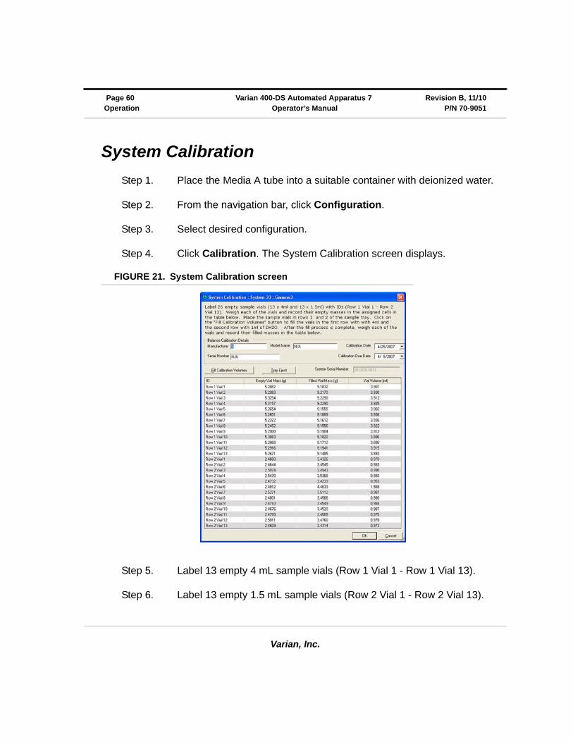
Step 4. Click Calibration. The System Calibration screen displays.
FIGURE 21. System Calibration screen
Step 5. Label 13 empty 4 mL sample vials (Row 1 Vial 1 - Row 1 Vial 13).
Step 6. Label 13 empty 1.5 mL sample vials (Row 2 Vial 1 - Row 2 Vial 13).

Varian, Inc.
Revision B, 11/10 Varian 400-DS Automated Apparatus 7 Page 61P/N 70-9051 Operator’s Manual Operation
Step 7. Weigh each of the vials and record the empty masses in the assigned cells in the table.
Step 8. Place the sample vials in row 1 (4 mL) and row 2 (1.5 mL) of the sample tray.
Step 9. Click Fill Calibration Volumes to fill the vials in the first row with 4 mL and the second row with 1 mL of deionized water.
Step 10. After the fill process is complete, weigh each of the vials and record their filled masses in the table. The vial volume calculates and displays in the table automatically.
Step 11. Click OK. The Reason for Change screen displays.
Step 12. Enter a reason code and change description and click OK.
Step 13. Highlight the appropriate system.
Step 14. Click Properties.
Step 15. Click Next and ensure the Volume Calibration Coefficients are visible.
Step 16. Click Finish.
Step 17. Close the System Configuration screen.
NoteThe software performs a Least Squares Fit analysis. The volume deviation from the curve is 1.5% of the vial volume. An automated error message is generated if the calibration fails.
Varian, Inc.
Page 62 Varian 400-DS Automated Apparatus 7 Revision B, 11/10Operation Operator’s Manual P/N 70-9051
Cell Calibration Temperatures
Step 1. Place the rinse media line into a suitable container holding deionized water.
Step 2. From the navigation bar, click Diagnostics. The Select Item screen displays.
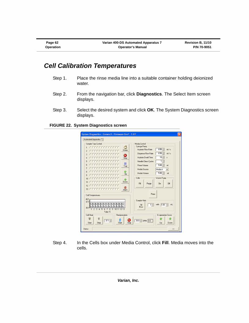
Step 3. Select the desired system and click OK. The System Diagnostics screen displays.
FIGURE 22. System Diagnostics screen
Step 4. In the Cells box under Media Control, click Fill. Media moves into the cells.
Varian, Inc.
Revision B, 11/10 Varian 400-DS Automated Apparatus 7 Page 63P/N 70-9051 Operator’s Manual Operation
Step 5. In the Cell Heat box, set the cell temperature to an appropriate temperature.
Step 6. Click . DO THE SAMPLE CELLS CONTAIN LIQUID? displays.
Step 7. Click Yes. The temperatures display in the Cell Temperature box.
Step 8. Set the reciprocation rate and click Run.
Step 9. Allow the media to equilibrate to the set temperature.
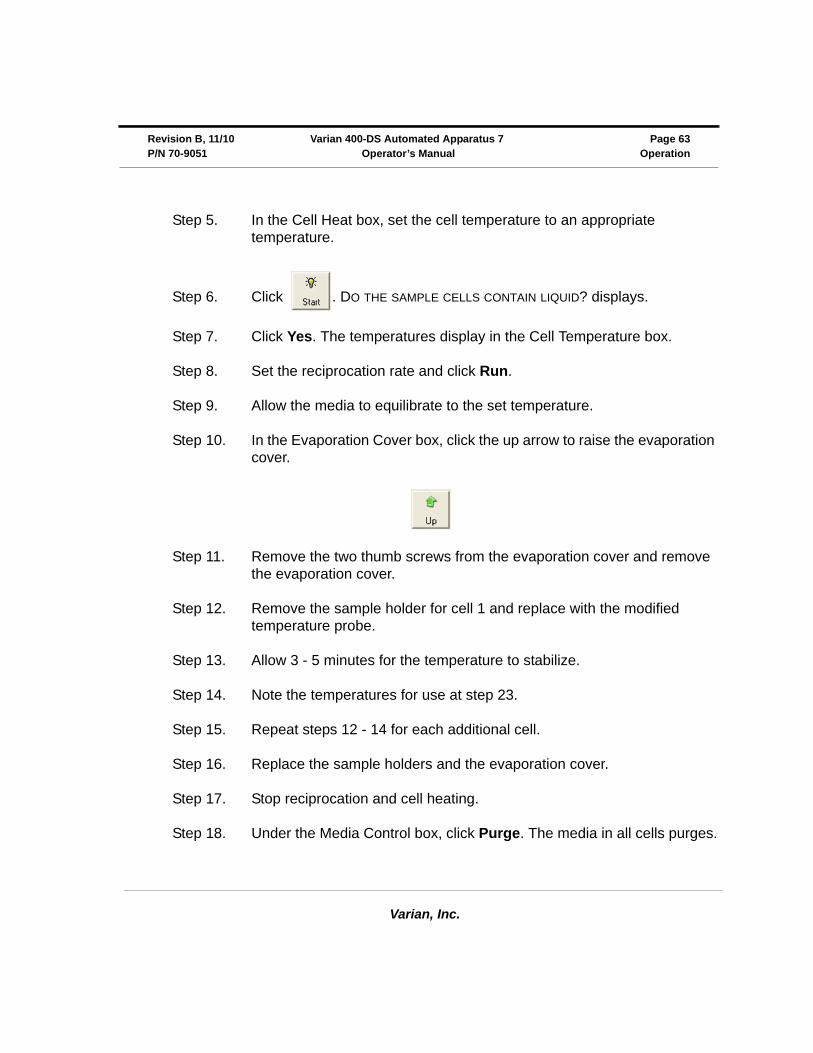
Step 10. In the Evaporation Cover box, click the up arrow to raise the evaporation cover.
Step 11. Remove the two thumb screws from the evaporation cover and remove the evaporation cover.
Step 12. Remove the sample holder for cell 1 and replace with the modified temperature probe.
Step 13. Allow 3 - 5 minutes for the temperature to stabilize.
Step 14. Note the temperatures for use at step 23.
Step 15. Repeat steps 12 - 14 for each additional cell.
Step 16. Replace the sample holders and the evaporation cover.
Step 17. Stop reciprocation and cell heating.
Step 18. Under the Media Control box, click Purge. The media in all cells purges.
Varian, Inc.
Page 64 Varian 400-DS Automated Apparatus 7 Revision B, 11/10Operation Operator’s Manual P/N 70-9051
Step 19. Close the Diagnostics screen.
Step 20. From the navigation bar, click Configuration. The System Configuration screen displays (see Figure 18, “System Configuration screen,” on page 50).
Step 21. Select the appropriate system and click Next.
Step 22. Enter the set point temperature as appropriate based on the cell calibration temperatures.
Step 23. Enter the temperature values for each cell (as noted in step 14) into the cell calibration field.
Step 24. Click Finish. The Reason for Change screen displays.
Step 25. Enter a reason code and change description and click OK.
Step 26. Close the System Configuration screen.
Manual Control/Diagnostics
To check the diagnostics of a dissolution apparatus, complete the procedures on the following pages. These procedures are performed on one system at a time. Repeat the procedures as applicable for each additional system.
Step 1. From the navigation bar, click Diagnostics. The Select Item screen displays.
Step 2. Select the desired system and click OK. The System Diagnostics screen displays (see Figure 22, “System Diagnostics screen,” on page 62).
Varian, Inc.
Revision B, 11/10 Varian 400-DS Automated Apparatus 7 Page 65P/N 70-9051 Operator’s Manual Operation
Verifying Sample Tray Control
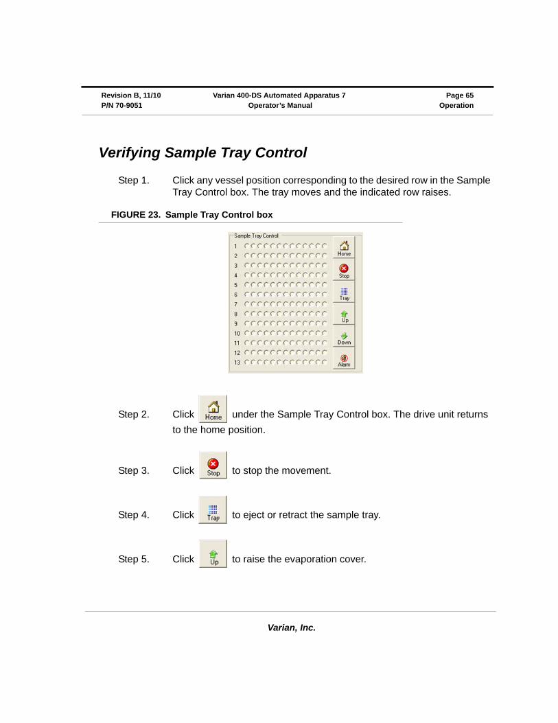
Step 1. Click any vessel position corresponding to the desired row in the Sample Tray Control box. The tray moves and the indicated row raises.
FIGURE 23. Sample Tray Control box
Step 2. Click under the Sample Tray Control box. The drive unit returns
to the home position.
Step 3. Click to stop the movement.
Step 4. Click to eject or retract the sample tray.
Step 5. Click to raise the evaporation cover.
Varian, Inc.
Page 66 Varian 400-DS Automated Apparatus 7 Revision B, 11/10Operation Operator’s Manual P/N 70-9051
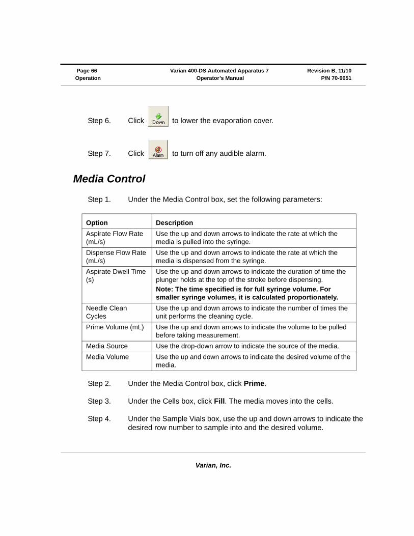
Step 6. Click to lower the evaporation cover.
Step 7. Click to turn off any audible alarm.
Media Control
Step 1. Under the Media Control box, set the following parameters:
Step 2. Under the Media Control box, click Prime.
Step 3. Under the Cells box, click Fill. The media moves into the cells.
Step 4. Under the Sample Vials box, use the up and down arrows to indicate the desired row number to sample into and the desired volume.
Option Description
Aspirate Flow Rate (mL/s)
Use the up and down arrows to indicate the rate at which the media is pulled into the syringe.
Dispense Flow Rate (mL/s)
Use the up and down arrows to indicate the rate at which the media is dispensed from the syringe.
Aspirate Dwell Time (s)
Use the up and down arrows to indicate the duration of time the plunger holds at the top of the stroke before dispensing.
Note: The time specified is for full syringe volume. For smaller syringe volumes, it is calculated proportionately.
Needle Clean Cycles
Use the up and down arrows to indicate the number of times the unit performs the cleaning cycle.
Prime Volume (mL) Use the up and down arrows to indicate the volume to be pulled before taking measurement.
Media Source Use the drop-down arrow to indicate the source of the media.
Media Volume Use the up and down arrows to indicate the desired volume of the media.

Varian, Inc.
Revision B, 11/10 Varian 400-DS Automated Apparatus 7 Page 67P/N 70-9051 Operator’s Manual Operation
Step 5. Under the Sample Vials box, click Fill Row. The media moves from the cell into the sample vial.
Step 6. Under the Waste Pump box, click On to turn on the waste pump.
Step 7. Under the Waste Pump box, click Off to turn off the waste pump.
Verifying the Cell Temperature
Step 1. In the Cell Heat box, use the up and down arrows to set the media cell temperature to an appropriate temperature (see the sample screen below).
Step 2. Click . DO THE SAMPLE CELLS CONTAIN LIQUID? displays.
Step 3. Click Yes. The temperatures display in the Cell Temperature box.
Step 4. As applicable, click .
Step 5. Under the Cells box, click Purge to purge the remaining media from the tube.
CautionDo not click Fill more than one time without purging in between. The media will overflow the cells.
Varian, Inc.
Page 68 Varian 400-DS Automated Apparatus 7 Revision B, 11/10Operation Operator’s Manual P/N 70-9051
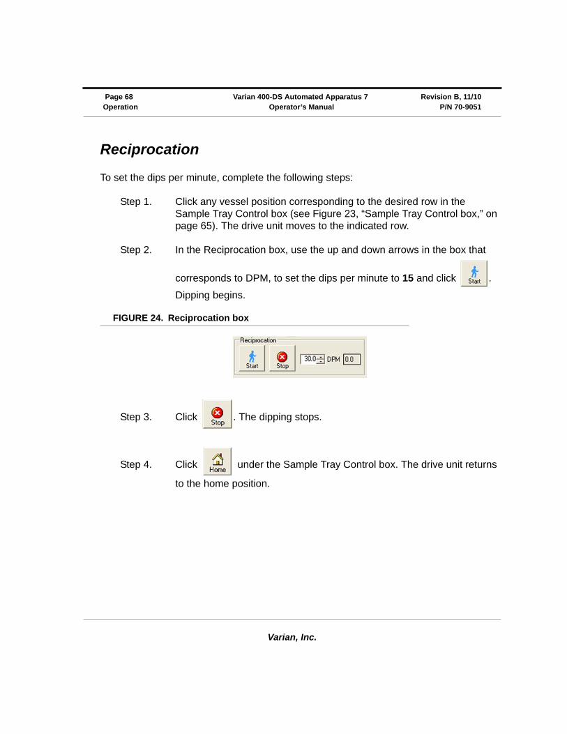
Reciprocation
To set the dips per minute, complete the following steps:
Step 1. Click any vessel position corresponding to the desired row in the Sample Tray Control box (see Figure 23, “Sample Tray Control box,” on page 65). The drive unit moves to the indicated row.
Step 2. In the Reciprocation box, use the up and down arrows in the box that
corresponds to DPM, to set the dips per minute to 15 and click .
Dipping begins.
FIGURE 24. Reciprocation box
Step 3. Click . The dipping stops.
Step 4. Click under the Sample Tray Control box. The drive unit returns
to the home position.
Varian, Inc.
Revision B, 11/10 Varian 400-DS Automated Apparatus 7 Page 69P/N 70-9051 Operator’s Manual Operation
Controlling the Evaporation Cover
To raise the evaporation cover, click in the Evaporation Cover box.
To lower the evaporation cover, click in the Evaporation Cover box.
Method Editor
All test parameters are entered via the Method Editor screen.
Function Procedure
Create a new method See “Creating a Method” on page 70.
Copy a method See “Copying Methods” on page 77.
Delete a method See “Deleting Methods” on page 77.
Edit an existing method See “Editing an Existing Method” on page 78.
Run a report of the method setup See “Method Report” on page 78.
View the method audit trail See “Show Audit Trail” on page 79.
Verify the integrity of a method See “Verify Integrity” on page 80.
Import or export the method between two 400-DS Workstations
See “Import/Export XML File” on page 80.

Varian, Inc.
Page 70 Varian 400-DS Automated Apparatus 7 Revision B, 11/10Operation Operator’s Manual P/N 70-9051
Creating a Method
To create a new method, complete the following steps:
Step 1. From the navigation bar, click Editor. The Methods screen displays.
FIGURE 25. Methods screen
Step 2. Click New Method. The Method Editor screen displays.
Varian, Inc.
Revision B, 11/10 Varian 400-DS Automated Apparatus 7 Page 71P/N 70-9051 Operator’s Manual Operation
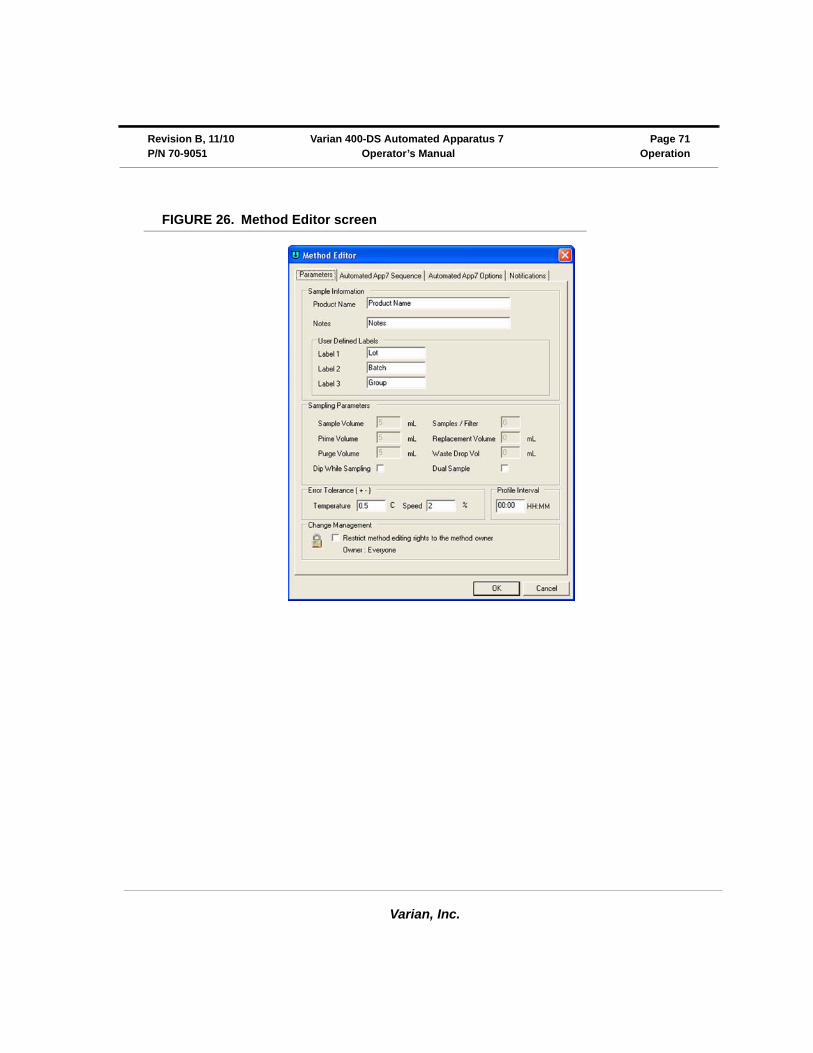
FIGURE 26. Method Editor screen
Varian, Inc.
Page 72 Varian 400-DS Automated Apparatus 7 Revision B, 11/10Operation Operator’s Manual P/N 70-9051
Step 3. Select the Parameters tab.
Following is a description of the Parameters tab options:
Step 4. Select the Automated App7 Sequence tab (see Figure 27, “Automated App7 Sequence tab,” on page 73).
Option Description
Sample Information
Product Name Enter the name of the product.
Notes Enter any relevant notes regarding the sample.
User Defined Labels
Label 1
Label 2
Label 3
The fields in this area have default values of LOT, BATCH, and GROUP. These fields are customizable; enter the information that best serves the needs of the method parameters.
Error Tolerance (±)
Temperature Enter the desired temperature fluctuation limit (±). If the tube temperature goes over or under the set temperature (see “Verifying the Cell Temperature” on page 67) by the amount of this tolerance, an error is recorded as part of the results.
Speed Enter the desired speed fluctuation limit (±). If the RPM goes over or under the set speed (see “Reciprocation” on page 68) by the amount of this tolerance, an error is recorded as part of the results.
Profile Interval Enter the timepoint in hh:mm format at which the temperature and speed settings are recorded.
Note: Profile measurements are optional. Values are always recorded at sample timepoints independent of this setting.
Change Management If applicable, select the box under Change Management in order to restrict the method editing rights to the current user or any user with VkModifyOthersMethod.
Varian, Inc.
Revision B, 11/10 Varian 400-DS Automated Apparatus 7 Page 73P/N 70-9051 Operator’s Manual Operation
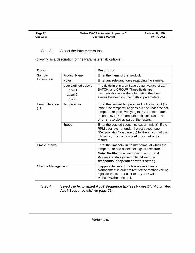
FIGURE 27. Automated App7 Sequence tab
Following is a description of the Automated App7 Sequence tab options:
Option Description
Sample Row Use the up and down arrows to indicate the row number for which the parameters are being set. After clicking Add to List, use the up and down arrows to indicate the next row.
Media Use the drop-down arrows to indicate Media A, Media B, Media C, Media D, or Media E.
Sampled Volume (mL) Use the up and down arrows to indicate appropriate volume based on your vial size.
Dissolution Volume (mL) Use the up and down arrows to indicate appropriate volume based on your cell size.

Varian, Inc.
Page 74 Varian 400-DS Automated Apparatus 7 Revision B, 11/10Operation Operator’s Manual P/N 70-9051
Step 5. Select the Automated App7 Options tab.
FIGURE 28. Automated App7 Options tab
Cell Temperature Enter the desired tube temperature in degrees Celsius. This can be entered for the first timepoint.
Hold Time (mm:ss) Enter the desired duration for the dip to remain at the bottom of the stroke in mm:ss format.
Dip Speed (DPM) Use the up and down arrows to indicate the desired dips per minute (DPM) for each applicable row of the 400-DS.
Dip Interval (hhh:mm:ss) Enter the desired duration for dipping in hhh:mm:ss format.
Option Description
Varian, Inc.
Revision B, 11/10 Varian 400-DS Automated Apparatus 7 Page 75P/N 70-9051 Operator’s Manual Operation
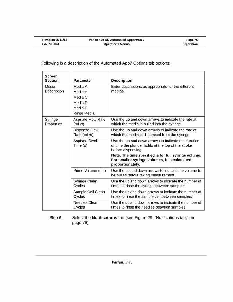
Following is a description of the Automated App7 Options tab options:
Step 6. Select the Notifications tab (see Figure 29, “Notifications tab,” on page 76).
Screen Section Parameter Description
Media Description
Media A
Media B
Media C
Media D
Media E
Rinse Media
Enter descriptions as appropriate for the different medias.
Syringe Properties
Aspirate Flow Rate (mL/s)
Use the up and down arrows to indicate the rate at which the media is pulled into the syringe.
Dispense Flow Rate (mL/s)
Use the up and down arrows to indicate the rate at which the media is dispensed from the syringe.
Aspirate Dwell Time (s)
Use the up and down arrows to indicate the duration of time the plunger holds at the top of the stroke before dispensing.
Note: The time specified is for full syringe volume. For smaller syringe volumes, it is calculated proportionately.
Prime Volume (mL) Use the up and down arrows to indicate the volume to be pulled before taking measurement.
Syringe Clean Cycles
Use the up and down arrows to indicate the number of times to rinse the syringe between samples.
Sample Cell Clean Cycles
Use the up and down arrows to indicate the number of times to rinse the sample cell between samples.
Needles Clean Cycles
Use the up and down arrows to indicate the number of times to rinse the needles between samples

Varian, Inc.
Page 76 Varian 400-DS Automated Apparatus 7 Revision B, 11/10Operation Operator’s Manual P/N 70-9051
FIGURE 29. Notifications tab
Step 7. Enter appropriate e-mail address(es) to receive notification of system operation.
Step 8. Indicate which options would require notification.
Step 9. Click OK to close the Method Editor screen.
Step 10. Close the Methods screen.
Varian, Inc.
Revision B, 11/10 Varian 400-DS Automated Apparatus 7 Page 77P/N 70-9051 Operator’s Manual Operation
Copying Methods
To copy a method, complete the following steps:
Step 1. From the navigation bar, click Editor. The Methods screen displays (see Figure 25, “Methods screen,” on page 70).
Step 2. Select the desired method.
Step 3. Click Copy Method.
Step 4. Click Paste. A new method displays. The description of the new method is Copy of....
Step 5. To change any of the parameters of the method, see “Editing an Existing Method” on page 78.
Deleting Methods
To delete a method, complete the following steps:
Step 1. From the navigation bar, click Editor. The Methods screen displays (see Figure 25, “Methods screen,” on page 70).
Step 2. Select the desired method.
Step 3. Click Delete.
Step 4. Click Yes.
Varian, Inc.
Page 78 Varian 400-DS Automated Apparatus 7 Revision B, 11/10Operation Operator’s Manual P/N 70-9051
Editing an Existing Method
To edit a method already entered on the 400-DS Workstation, complete the following steps:
Step 1. From the navigation bar, click Editor. The Methods screen displays (see Figure 25, “Methods screen,” on page 70).
Step 2. Click the desired method.
Step 3. Click Properties on the navigation bar. The Method Editor screen displays (see Figure 26, “Method Editor screen,” on page 71).
Step 4. Select the appropriate tabs and change the relevant information in the same manner that the method was created.
Method Report
To display a report of the method parameters, complete the following steps:
Step 1. From the navigation bar, click Editor. The Methods screen displays (see Figure 25, “Methods screen,” on page 70).
Step 2. Select the desired system configuration.
Step 3. Click Report. The Version Selection screen displays.
NoteAlternately, you can double-click the desired method or right-click the desired method and select Properties. The Method Editor screen displays as a result of any of these actions.
Varian, Inc.
Revision B, 11/10 Varian 400-DS Automated Apparatus 7 Page 79P/N 70-9051 Operator’s Manual Operation
Step 4. If applicable, indicate which version and click OK.
Step 5. The method report displays. The report can be printed, exported, searched, verified, and/or signed.
Audit Trail
Once a method has completed, the results are available for review, audited modification, and electronic signature. The software maintains complete history for all runs executed on the system. Results can be previewed and printed.
Show Audit Trail
To display the audit trail for a method, complete the following steps:
Step 1. From the navigation bar, click Editor. The Methods screen displays (see Figure 25, “Methods screen,” on page 70).
Step 2. Select the method and click Show Audit Trail. The Method Audit Trail screen displays.
Step 3. Select two or more versions and click Differences in the navigation bar. A change report displays. The report can be printed or exported.
NoteEach time a method is saved, a new version is created. To create a report of a version other than the most recently saved, indicate the appropriate version number on the Version Selection screen.
NoteAlternately, you can right-click the desired method and select Show Audit Trail. The Method Audit Trail screen displays as a result of either of these actions.
Varian, Inc.
Page 80 Varian 400-DS Automated Apparatus 7 Revision B, 11/10Operation Operator’s Manual P/N 70-9051
Verify Integrity
To verify that the method has not been changed outside of the application, complete the following steps:
Step 1. From the navigation bar, click Editor. The Methods screen displays (see Figure 25, “Methods screen,” on page 70).
Step 2. Select the method and click Verify Integrity. Either the data is verified successfully or the user is directed to contact their system administrator.
Import/Export XML File
To use an existing method from one 400-DS Workstation on a different 400-DS Workstation, you can export and import the method as an XML file.
To export the method, complete the following steps:
Step 1. From the navigation bar, click Editor. The Methods screen displays (see Figure 25, “Methods screen,” on page 70).
Step 2. Select the desired method.
Step 3. Click Export. The Version Selection screen displays.
NoteAlternately, you can right-click the desired method and select Verify Integrity. The integrity of the method is checked as a result of either of these actions.
NoteAlternately, you can right-click the desired method and select Export. The Version Selection screen displays as a result of either of these actions.
Varian, Inc.
Revision B, 11/10 Varian 400-DS Automated Apparatus 7 Page 81P/N 70-9051 Operator’s Manual Operation
Step 4. If applicable, indicate which version to export and click OK. The Export Method to XML File screen displays.
Step 5. Indicate the directory and file name and click Save. The code is saved as an XML file which displays in Notepad.
Step 6. Close the Notepad file.
To import the XML file at another 400-DS Workstation, complete the following steps:
Step 1. From the navigation bar, click Editor. The Methods screen displays (see Figure 25, “Methods screen,” on page 70).
Step 2. Click Import. The Import Method from XML File screen displays.
Step 3. Select the appropriate directory and file name and click Open. The method displays on the Method screen.
NoteEach time a method is saved, a new version is created. To export a version other than the most recently saved, indicate the appropriate version number on the Version Selection screen.
NoteAlternately, you can right-click the desired method and select Import. The Import Method from XML File screen displays as a result of either of these actions.
Varian, Inc.
Page 82 Varian 400-DS Automated Apparatus 7 Revision B, 11/10Operation Operator’s Manual P/N 70-9051
Running the Method
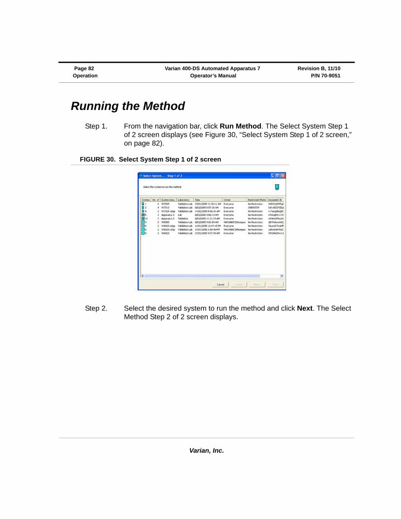
Step 1. From the navigation bar, click Run Method. The Select System Step 1 of 2 screen displays (see Figure 30, “Select System Step 1 of 2 screen,” on page 82).
FIGURE 30. Select System Step 1 of 2 screen
Step 2. Select the desired system to run the method and click Next. The Select Method Step 2 of 2 screen displays.
Varian, Inc.
Revision B, 11/10 Varian 400-DS Automated Apparatus 7 Page 83P/N 70-9051 Operator’s Manual Operation
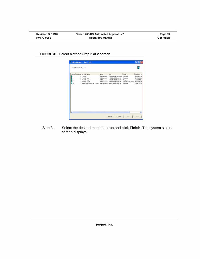
FIGURE 31. Select Method Step 2 of 2 screen
Step 3. Select the desired method to run and click Finish. The system status screen displays.
Varian, Inc.
Page 84 Varian 400-DS Automated Apparatus 7 Revision B, 11/10Operation Operator’s Manual P/N 70-9051
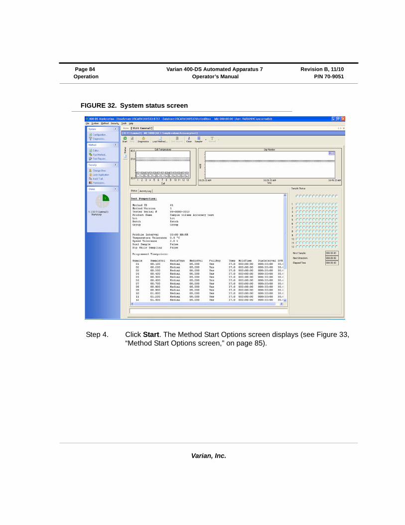
FIGURE 32. System status screen
Step 4. Click Start. The Method Start Options screen displays (see Figure 33, “Method Start Options screen,” on page 85).
Varian, Inc.
Revision B, 11/10 Varian 400-DS Automated Apparatus 7 Page 85P/N 70-9051 Operator’s Manual Operation
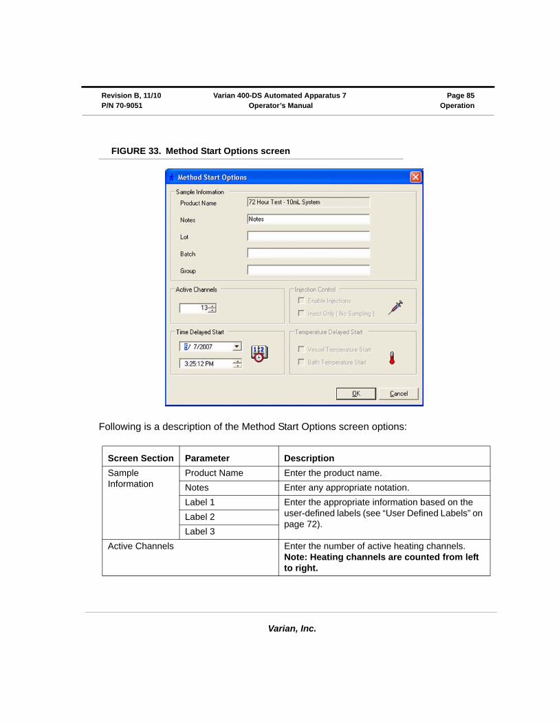
FIGURE 33. Method Start Options screen
Following is a description of the Method Start Options screen options:
Screen Section Parameter Description
Sample Information
Product Name Enter the product name.
Notes Enter any appropriate notation.
Label 1 Enter the appropriate information based on the user-defined labels (see “User Defined Labels” on page 72).
Label 2
Label 3
Active Channels Enter the number of active heating channels. Note: Heating channels are counted from left to right.
Varian, Inc.
Page 86 Varian 400-DS Automated Apparatus 7 Revision B, 11/10Operation Operator’s Manual P/N 70-9051
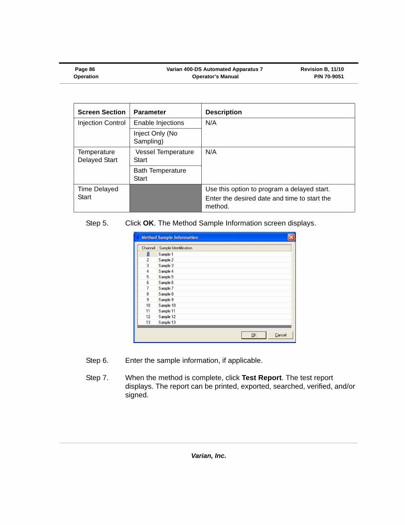
Step 5. Click OK. The Method Sample Information screen displays.
Step 6. Enter the sample information, if applicable.
Step 7. When the method is complete, click Test Report. The test report displays. The report can be printed, exported, searched, verified, and/or signed.
Injection Control Enable Injections N/A
Inject Only (No Sampling)
Temperature Delayed Start
Vessel Temperature Start
N/A
Bath Temperature Start
Time Delayed Start
Use this option to program a delayed start.
Enter the desired date and time to start the method.
Screen Section Parameter Description
Varian, Inc.
Revision B, 11/10 Varian 400-DS Automated Apparatus 7 Page 87P/N 70-9051 Operator’s Manual Operation
Test Reports
To display a report of the completed method, complete the following steps:
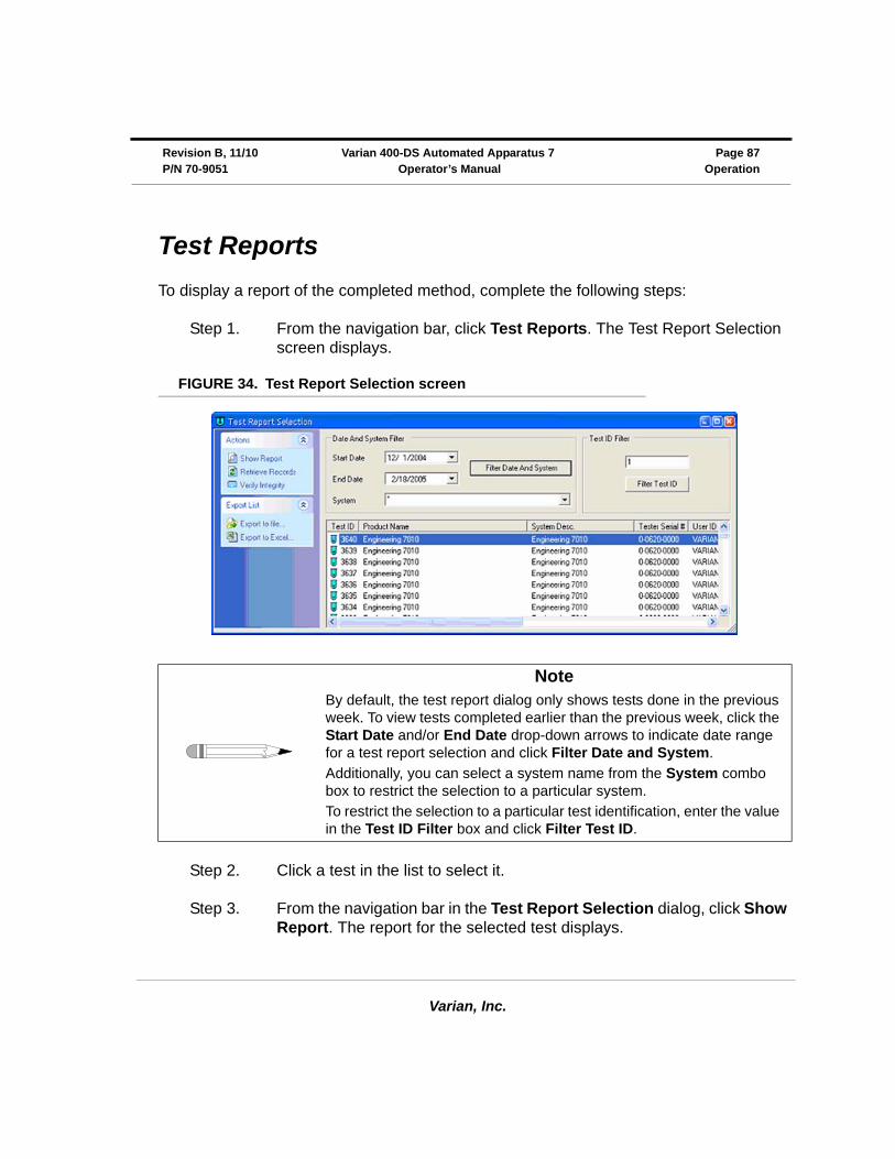
Step 1. From the navigation bar, click Test Reports. The Test Report Selection screen displays.
FIGURE 34. Test Report Selection screen
Step 2. Click a test in the list to select it.
Step 3. From the navigation bar in the Test Report Selection dialog, click Show Report. The report for the selected test displays.
NoteBy default, the test report dialog only shows tests done in the previous week. To view tests completed earlier than the previous week, click the Start Date and/or End Date drop-down arrows to indicate date range for a test report selection and click Filter Date and System.
Additionally, you can select a system name from the System combo box to restrict the selection to a particular system.
To restrict the selection to a particular test identification, enter the value in the Test ID Filter box and click Filter Test ID.
Varian, Inc.
Page 88 Varian 400-DS Automated Apparatus 7 Revision B, 11/10Operation Operator’s Manual P/N 70-9051
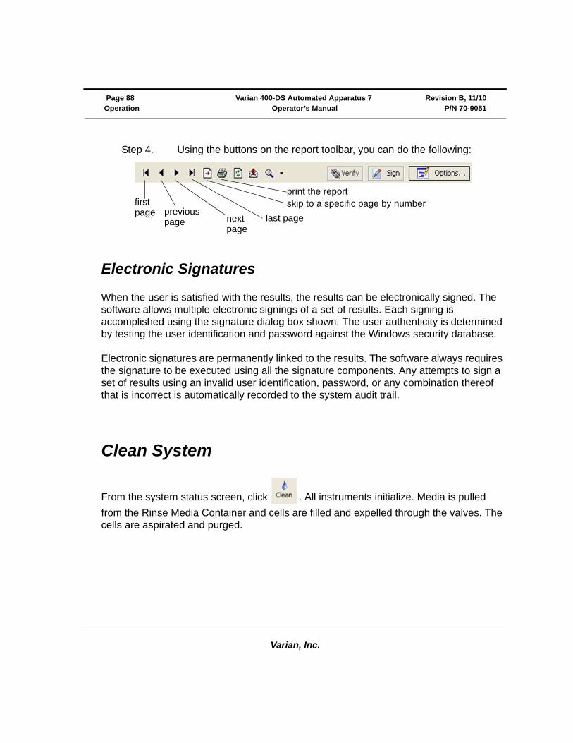
Step 4. Using the buttons on the report toolbar, you can do the following:
Electronic Signatures
When the user is satisfied with the results, the results can be electronically signed. The software allows multiple electronic signings of a set of results. Each signing is accomplished using the signature dialog box shown. The user authenticity is determined by testing the user identification and password against the Windows security database.
Electronic signatures are permanently linked to the results. The software always requires the signature to be executed using all the signature components. Any attempts to sign a set of results using an invalid user identification, password, or any combination thereof that is incorrect is automatically recorded to the system audit trail.
Clean System
From the system status screen, click . All instruments initialize. Media is pulled
from the Rinse Media Container and cells are filled and expelled through the valves. The cells are aspirated and purged.
print the reportskip to a specific page by numberfirst
page previouspage next
pagelast page
Varian, Inc.
Chapter 5 Maintenance
Periodic Maintenance
Periodic maintenance intervals may vary depending on frequency of instrument usage.
WarningThe tester contains electrical circuits, devices, and components operating at dangerous voltages. Contact with these circuits, devices, and components can cause death, serious injury, or painful electric shock.
WarningThe apparatus should be disconnected from AC power before conducting cleaning or maintenance.
Page 90 Varian 400-DS Automated Apparatus 7 Revision B, 11/10Maintenance Operator’s Manual P/N 70-9051
Varian, Inc.
Routine Maintenance (to be Performed Between Each Dissolution Method
• All parts of the 400-DS exposed to the dissolution medium should be cleaned after each use. Parts made from stainless steel are particularly susceptible to surface corrosion if not cleaned immediately after use. If any stainless steel parts show signs of surface discoloration, lightly wipe the surface with a soft cloth or nonabrasive pad to remove it.
• Execute the Clean System cycle using the 400-DS Workstation software (“Clean System” on page 88). Ensure an appropriate cleaning solution is in place to thoroughly rinse the media lines and sample cells.
• If an alternate cleaning solution is used, it is recommended that all the media lines are rinsed with deionized water at the end of the cleaning procedure.
Sample Holders
• Clean sample holders thoroughly after each use and place them in an ultrasonic bath for a few minutes, if necessary.
• When using corrosive materials such as hydrochloric acid or medium containing salts, be sure to rinse the holders with deionized water immediately after use. Dry completely with a soft towel or cloth (preferably lint-free).
• Do not clean the sample holders with abrasive cleansers or cloths. Use deionized water whenever possible. If you must use cleanser or solvent, be sure that it is as mild as possible, non-abrasive, and fully compatible with fluorocarbons and stainless steel before use.
• It is suggested that the sample holders are cleaned by hand. Use of a laboratory dishwasher is NOT recommended.
• Handle with care at all times.
• Store the sample holders properly between each use.

Varian, Inc.
Revision B, 11/10 Varian 400-DS Automated Apparatus 7 Page 91 P/N 70-9051 Operator’s Manual Maintenance
Non-Routine Maintenance (to be Performed at Pre-Determined Intervals)
It is recommended that the following procedures be performed by a properly trained service technician.
• Remove and inspect all sample cells for signs of damage. Replace as necessary. Clean the sample cells thoroughly, especially the area that typically covers the seal.
• Clean the entire external surface of the instrument including top cover and syringe pump window.
• Inspect and clean the air filter(s). Replace if necessary.
• Inspect all sample cell holder seals. Re-grease the o-rings, if necessary, using a pre-approved lubricant (e.g. Krytox®). Replace any o-rings that appear dried or cracked.
• Inspect all external media lines. Replace if necessary.
• Check the magnet plate for free play.
• Check the evaporation mechanism for free play.
• Inspect the evaporation cover seals.
• Remove, inspect, and clean the needles. Place them in an ultrasonic bath for a few minutes, if necessary.
• Verify the following limit switch/alarm operations: home position, top cover (open/close), front door, and sample tray (lift empty sample row). See “Verifying Sample Tray Control” on page 65.
• Verify proper operation of all LEDs (4 total).
Open the front door (sample tray compartment) of the Varian 400-DS.
• Lubricate reciprocation slide rail using a pre-approved lubricant. Using the Diagnostics portion of the software (“Manual Control/Diagnostics” on page 64), move the sample tray from row to row to work in the lubricant.
• Inspect the front door bumper.
• Inspect waste line (front view).

Page 92 Varian 400-DS Automated Apparatus 7 Revision B, 11/10Maintenance Operator’s Manual P/N 70-9051
Varian, Inc.
Power OFF the 400-DS and disconnect the power cord. Remove the back cover of the 400-DS to perform the following:
• Lubricate the ball screw on syringe pump.
• Lubricate all moving pieces of syringe pump.
• Inspect the main drive belt.
• Inspect/clean the waste row.
• Inspect/clean the waste tubing.
• Inspect all internal stainless steel components for signs of discoloration. Lightly wipe the surface with a soft cloth to remove, if necessary.
• Lubricate the main rails.
• Inspect the waste line (rear view).
• Check lift blocks for free play.
Varian, Inc.
Chapter 6 Service and Warranty
The warranty is provided by Varian, Inc. or one of its authorized representatives.
Service and Warranty Information
Varian dissolution products carry a one-year warranty on parts and labor. The Dissolution Systems Service Department (or one of its representatives) will, at its option, either repair or replace any mechanical and electrical components in your instrument which prove to be defective. During the first year of warranty coverage, there is no charge for the labor to repair your unit. The Dissolution Systems Service Department (or one of its representatives) will determine the best site to repair the unit, either onsite or returned to Varian, Inc. Any onsite warranty services are provided only at the initial installation point. Installation and onsite warranty services are available only in Dissolution Systems service travel areas.

Page 94 Varian 400-DS Automated Apparatus 7 Revision B, 11/10Service and Warranty Operator’s Manual P/N 70-9051
Varian, Inc.
Exclusions and Limitations
Excluded from this warranty are expendable or consumable items such as, but not limited to, paddles, baskets, vessels, and acrylic water baths. Also excluded are defects from improper or inadequate maintenance by the customer, user-induced chemical action or contamination, unauthorized modification or misuse, and improper site preparation and maintenance.
Operation of software is not warranted to be uninterrupted or error-free.
Obtaining Warranty Service
To obtain warranty service in the United States, contact the Dissolution Systems Service Department at 800.229.1108 to obtain authorization to return units for repair. At the option of the customer, onsite warranty service is available, but travel charges may be incurred. The customer should prepay all shipping charges for products returned to the Dissolution Systems Service Department (unless otherwise authorized), and Varian, Inc. will pay all charges for return to the customer.
Warranty Limitations
Varian, Inc. makes no other warranty, either express or implied, with respect to this product. Specifically disclaimed are any implied warranties of merchantability and fitness for a particular use. In no event will Varian, Inc. be liable for any indirect, incidental, or consequential damages arising from the use of this product. This warranty gives you specific legal rights which may vary from state to state or province to province, so you may have other rights and some of these exclusions may not apply to you.
Varian, Inc.
Revision B, 11/10 Varian 400-DS Autoamted Apparatus 7 Page 95 P/N 70-9051 Operator’s Manual Service and Warranty
Exclusive Remedies
The remedies provided herein are the customer’s sole and exclusive remedies. In no event shall Varian, Inc. or its representatives be liable for any direct, indirect, special, incidental, or consequential damages, whether based on contract, tort, or any other legal theory. Some states or provinces do not allow the exclusion or limitation of incidental or consequential damages, so the above limitation or exclusion may not apply to you.

Page 96 Varian 400-DS Automated Apparatus 7 Revision B, 11/10Service and Warranty Operator’s Manual P/N 70-9051
Varian, Inc.
This page was intentionally left blank, except for this message.
Varian, Inc.
aaccessories 23add new dissolution server screen 42application, configuring 43audit trail 49, 79automated apparatus 7 workstationscreen 48
bbrowse dissolution servers screen 42
ccable connections
multiple system 29single system 29
change management 72change user 49clean system 88configuration dialog screen
miscellaneous tab 45security tab 43
configuring automated apparatus 7
workstation 50configuring the application 43conventions 20copying a system configuration 54copying methods 77creating a method 70
ddatabase, attaching 33deleting a system configuration 54deleting methods 77diagnostics 64dissolution server selection 41dissoservice manager screen 37
tools menu 38dissoservice options screen 39
eediting an existing method 78editing an existing system configuration56electronic signatures 88
Index
Index
Varian, Inc.
e-mail notification configuration 37error tolerance 72exclusions 94exclusive remedies 95export xml file 58, 80
hhazards 11
iimport xml file 58, 80initial power up 32introduction 19
llimitations 94local security policy 35local users and groups screen 44lock application 49logon 47logon screen 41, 47
mmaintenance 89manual control 64method editor 69method editor screen 71method report 78method start options screen 85methods screen 70minimum pc configuration 28msde manager screen 34
oobtaining warranty service 94
ppc requirements, minimum 28pc, setting up 28periodic maintenance 89permissions 49physical parameters, usp 20power up 32profile interval 72
rreader comment form 101report toolbar 88run method 82
ssafety features 20safety practices 11sample information 72screen options
automated apparatus 7 workstation49
method start options screen 85system editor 51
security 49select method step 2 of 2 screen 83select system step 1 of 2 screen 82selecting dissolution server 41serial numbers 55service 93setting up your pc 28show audit trail 57, 79starting dissolution workstation 40status 49system configuration report 56system configuration screen 50system editing rights 52system editor screen 51system status screen 84
ttab options
method editor
Parameters tab 72test report selection screen 87test reports 87
uuser administration 47usp
physical parameters 20
vverify integrity 58, 80

Varian, Inc.
Index Index
wwarranty 93warranty limitations 94windows security alert screen 40
Index
Varian, Inc.
This page was intentionally left blank, except for this message.
Varian 400-DS Automated Apparatus 7 Operator’s Manual P/N 70-9051 Revision B
Tell Us How We Are Doing
We listen to our customers. We work hard to make our technical documentation user friendly, and to make the information in our manuals easy to retrieve and use. We’d like you to tell us the kinds of additional information you’d find helpful in our documentation. Your feedback will be carefully considered when we prepare future editions of this manual.
This manual should contain the following additional information:
The most useful thing about this book is:
This manual would be more helpful if:
My general impressions of this book are:
May we contact you regarding your comments? ____ YES ____ NO (If yes, please write your name, address, and telephone number here.)
Please return this form via mail to: Technical Writing/Dissolution Systems, Varian, Inc., 13000 Weston Parkway, Cary, North Carolina 27513-2250 USA. Optionally, you can return this form via fax at 1.919.677.1550. Always, feel free to telephone us to discuss your comments at 1.800.229.1108.