Embed Size (px)
Citation preview
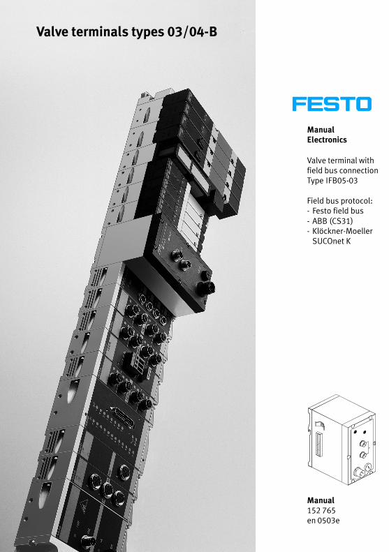
ManualElectronics
Valve terminal withfield bus connectionType IFB05−03
Field bus protocol:− Festo field bus− ABB (CS31)− Klöckner−Moeller SUCOnet K
Manual152 765en 0503e
Valve terminals types 03/04−B

Contents and general instructions
IFesto P.BE−VIFB5−03−EN en 0503e
Authors U. Reimann, E. Klotz, H. Hohner. . . . . . . . . . . . . . .
Editors H.J. Drung, M.Holder. . . . . . . . . . . . . . . . . . . . . . . .
Original de. . . . . . . . . . . . . . . . . . . . . . . . . . . . . . . . . . . . . . .
Translation transline Deutschland GmbH. . . . . . . . . . . . . . .
Layout Festo AG & Co., Dept. KG−GD. . . . . . . . . . . . . . . . . . .
Typesetting DUCOM. . . . . . . . . . . . . . . . . . . . . . . . . . . . . . . .
Edition en 0503e. . . . . . . . . . . . . . . . . . . . . . . . . . . . . . . . . .
Title MANUAL−EN. . . . . . . . . . . . . . . . . . . . . . . . . . . . . . . . . .
Designation P.BE−VIFB6−03−EN. . . . . . . . . . . . . . . . . . . . . . .
Orderno. 152 765. . . . . . . . . . . . . . . . . . . . . . . . . . . . . . . . .
E (Festo AG&Co., D73726 Esslingen, Federal Republic ofGermany, 2000)Internet: http://www.festo.comE−mail: [email protected]
The copying, distribution and utilization of this document as wellas the communication of its contents to others without expressedauthorization is prohibited. Offenders will be held liable for thepayment of damages. All rights reserved, in particular the right tocarry out patent, utility model or ornamental design registration.
Contents and general instructions
II Festo P.BE−VIFB5−03−EN en 0503e
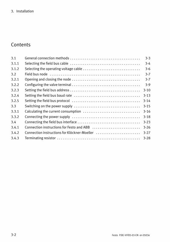
Contents
Intended use V. . . . . . . . . . . . . . . . . . . . . . . . . . . . . . . . . . . . . . . . . . . . . . . . . . . . . . . . . .
Target group V. . . . . . . . . . . . . . . . . . . . . . . . . . . . . . . . . . . . . . . . . . . . . . . . . . . . . . . . . .
Service V. . . . . . . . . . . . . . . . . . . . . . . . . . . . . . . . . . . . . . . . . . . . . . . . . . . . . . . . . . . . . . .
Important user instructions VI. . . . . . . . . . . . . . . . . . . . . . . . . . . . . . . . . . . . . . . . . . . . . .
Abbreviations VIII. . . . . . . . . . . . . . . . . . . . . . . . . . . . . . . . . . . . . . . . . . . . . . . . . . . . . . . . .
Manuals for this valve terminal X. . . . . . . . . . . . . . . . . . . . . . . . . . . . . . . . . . . . . . . . . . .
Additional modules for this valve terminal XI. . . . . . . . . . . . . . . . . . . . . . . . . . . . . . . . . .
1. Summary of components 1−1. . . . . . . . . . . . . . . . . . . . . . . . . . . . . . . . . . . . . . . .
1.1 Summary of multifunctional Festo valve terminals 1−3. . . . . . . . . . . . . . . . . . . .
1.2 Description of components 1−4. . . . . . . . . . . . . . . . . . . . . . . . . . . . . . . . . . . . . . .
1.2.1 Types 03/04−B electric modules 1−4. . . . . . . . . . . . . . . . . . . . . . . . . . . . . . . . . . .
1.2.2 Type 03: MIDI pneumatic modules 1−5. . . . . . . . . . . . . . . . . . . . . . . . . . . . . . . . .
1.2.3 Type 03: MAXI pneumatic modules 1−6. . . . . . . . . . . . . . . . . . . . . . . . . . . . . . . . .
1.2.4 Type 04−B ISO pneumatic modules 1−7. . . . . . . . . . . . . . . . . . . . . . . . . . . . . . . . .
1.3 Method of operation 1−8. . . . . . . . . . . . . . . . . . . . . . . . . . . . . . . . . . . . . . . . . . . .
2. Fitting 2−1. . . . . . . . . . . . . . . . . . . . . . . . . . . . . . . . . . . . . . . . . . . . . . . . . . . . . . . .
2.1 Fitting the modules and components 2−3. . . . . . . . . . . . . . . . . . . . . . . . . . . . . . .
2.1.1 Earthing the end plates 2−4. . . . . . . . . . . . . . . . . . . . . . . . . . . . . . . . . . . . . . . . . .
2.2 Fitting onto a hat rail (type 03) 2−6. . . . . . . . . . . . . . . . . . . . . . . . . . . . . . . . . . . .
2.3 Fitting the valve terminal onto a wall 2−9. . . . . . . . . . . . . . . . . . . . . . . . . . . . . . .
3. Installation 3−1. . . . . . . . . . . . . . . . . . . . . . . . . . . . . . . . . . . . . . . . . . . . . . . . . . .
3.1 General connection methods 3−3. . . . . . . . . . . . . . . . . . . . . . . . . . . . . . . . . . . . . .
3.1.1 Selecting the field bus cable 3−4. . . . . . . . . . . . . . . . . . . . . . . . . . . . . . . . . . . . . .
3.1.2 Selecting the operating voltage cable 3−6. . . . . . . . . . . . . . . . . . . . . . . . . . . . . . .
3.2 Field bus node 3−7. . . . . . . . . . . . . . . . . . . . . . . . . . . . . . . . . . . . . . . . . . . . . . . . .
3.2.1 Opening and closing the node 3−7. . . . . . . . . . . . . . . . . . . . . . . . . . . . . . . . . . . . .
3.2.2 Configuring the valve terminal 3−9. . . . . . . . . . . . . . . . . . . . . . . . . . . . . . . . . . . . .
3.2.3 Setting the field bus address 3−10. . . . . . . . . . . . . . . . . . . . . . . . . . . . . . . . . . . . . .
3.2.4 Setting the field bus baud rate 3−13. . . . . . . . . . . . . . . . . . . . . . . . . . . . . . . . . . . .
Contents and general instructions
IIIFesto P.BE−VIFB5−03−EN en 0503e
3.2.5 Setting the field bus protocol 3−14. . . . . . . . . . . . . . . . . . . . . . . . . . . . . . . . . . . . .
3.3 Switching on the power supply 3−15. . . . . . . . . . . . . . . . . . . . . . . . . . . . . . . . . . . .
3.3.1 Calculating the current consumption 3−16. . . . . . . . . . . . . . . . . . . . . . . . . . . . . . .
3.3.2 Connecting the power supply 3−18. . . . . . . . . . . . . . . . . . . . . . . . . . . . . . . . . . . . .
3.4 Connecting the field bus interface 3−23. . . . . . . . . . . . . . . . . . . . . . . . . . . . . . . . . .
3.4.1 Connection instructions for Festo and ABB 3−26. . . . . . . . . . . . . . . . . . . . . . . . . .
3.4.2 Connection instructions for Klöckner−Moeller 3−27. . . . . . . . . . . . . . . . . . . . . . . .
3.4.3 Terminating resistor 3−28. . . . . . . . . . . . . . . . . . . . . . . . . . . . . . . . . . . . . . . . . . . . .
4. Commissioning 4−1. . . . . . . . . . . . . . . . . . . . . . . . . . . . . . . . . . . . . . . . . . . . . . . .
4.1 Addressing and configuring the valve terminal 4−3. . . . . . . . . . . . . . . . . . . . . . .
4.1.1 Ascertaining the configuration data 4−3. . . . . . . . . . . . . . . . . . . . . . . . . . . . . . . .
4.1.2 Address assignment of the valve terminal 4−6. . . . . . . . . . . . . . . . . . . . . . . . . . .
4.1.3 Address assignment after extension/conversion 4−11. . . . . . . . . . . . . . . . . . . . . .
4.2 General commissioning instructions 4−13. . . . . . . . . . . . . . . . . . . . . . . . . . . . . . . .
4.2.1 Switching on the power supply 4−14. . . . . . . . . . . . . . . . . . . . . . . . . . . . . . . . . . . .
4.3 Commissioning the Festo field bus 4−15. . . . . . . . . . . . . . . . . . . . . . . . . . . . . . . . .
4.3.1 Configuration 4−15. . . . . . . . . . . . . . . . . . . . . . . . . . . . . . . . . . . . . . . . . . . . . . . . . .
4.3.2 Addressing 4−17. . . . . . . . . . . . . . . . . . . . . . . . . . . . . . . . . . . . . . . . . . . . . . . . . . . .
4.4 Commissioning the ABB CS31 4−20. . . . . . . . . . . . . . . . . . . . . . . . . . . . . . . . . . . . .
4.4.1 General information 4−20. . . . . . . . . . . . . . . . . . . . . . . . . . . . . . . . . . . . . . . . . . . . .
4.4.2 CS31 central unit as bus master 4−22. . . . . . . . . . . . . . . . . . . . . . . . . . . . . . . . . . .
4.4.3 T200 / 07CS61 as bus master 4−24. . . . . . . . . . . . . . . . . . . . . . . . . . . . . . . . . . . . .
4.4.4 T200 / 07CS61 as bus master 4−26. . . . . . . . . . . . . . . . . . . . . . . . . . . . . . . . . . . . .
4.4.5 Transmission times 4−28. . . . . . . . . . . . . . . . . . . . . . . . . . . . . . . . . . . . . . . . . . . . . .
4.5 Commissioning Klöckner−Moeller 4−29. . . . . . . . . . . . . . . . . . . . . . . . . . . . . . . . . .
4.5.1 Configuration 4−29. . . . . . . . . . . . . . . . . . . . . . . . . . . . . . . . . . . . . . . . . . . . . . . . . .
4.5.2 Addressing Klöckner−Moeller 4−30. . . . . . . . . . . . . . . . . . . . . . . . . . . . . . . . . . . . . .
5. Diagnosis and error treatment 5−1. . . . . . . . . . . . . . . . . . . . . . . . . . . . . . . . . . . .
5.1 Summary of diagnostic possibilities 5−3. . . . . . . . . . . . . . . . . . . . . . . . . . . . . . . .
5.2 On−the−spot diagnosis 5−4. . . . . . . . . . . . . . . . . . . . . . . . . . . . . . . . . . . . . . . . . . .
5.2.1 LEDs on the bus node 5−4. . . . . . . . . . . . . . . . . . . . . . . . . . . . . . . . . . . . . . . . . . .
5.2.2 LEDs of the valves 5−7. . . . . . . . . . . . . . . . . . . . . . . . . . . . . . . . . . . . . . . . . . . . . . .

Contents and general instructions
IV Festo P.BE−VIFB5−03−EN en 0503e
5.2.3 LEDs of the input/output modules 5−9. . . . . . . . . . . . . . . . . . . . . . . . . . . . . . . . .
5.2.4 Testing the valves 5−11. . . . . . . . . . . . . . . . . . . . . . . . . . . . . . . . . . . . . . . . . . . . . . .
5.3 Status bits 5−14. . . . . . . . . . . . . . . . . . . . . . . . . . . . . . . . . . . . . . . . . . . . . . . . . . . . .
5.3.1 Short circuit/overload 5−16. . . . . . . . . . . . . . . . . . . . . . . . . . . . . . . . . . . . . . . . . . .
5.4 Diagnosis with the field bus 5−17. . . . . . . . . . . . . . . . . . . . . . . . . . . . . . . . . . . . . . .
5.4.1 Diagnostic byte 5−18. . . . . . . . . . . . . . . . . . . . . . . . . . . . . . . . . . . . . . . . . . . . . . . . .
5.4.2 Festo field bus 5−19. . . . . . . . . . . . . . . . . . . . . . . . . . . . . . . . . . . . . . . . . . . . . . . . .
5.4.3 Diagnosis via ABB CS31 5−21. . . . . . . . . . . . . . . . . . . . . . . . . . . . . . . . . . . . . . . . . .
5.4.4 Diagnosis with Klöckner−Moeller SUCOnet K 5−26. . . . . . . . . . . . . . . . . . . . . . . . .
5.4.5 Position of the status bits 5−27. . . . . . . . . . . . . . . . . . . . . . . . . . . . . . . . . . . . . . .
5.5 Error treatment 5−28. . . . . . . . . . . . . . . . . . . . . . . . . . . . . . . . . . . . . . . . . . . . . . . . .
5.6 Type 04−B Fuses for the pilot solenoids 5−29. . . . . . . . . . . . . . . . . . . . . . . . . . . . .
A. Technical appendix A−1. . . . . . . . . . . . . . . . . . . . . . . . . . . . . . . . . . . . . . . . . . . . .
A.1 Technical specifications A−3. . . . . . . . . . . . . . . . . . . . . . . . . . . . . . . . . . . . . . . . . .
A.2 Cable length and cross−sectional area A−6. . . . . . . . . . . . . . . . . . . . . . . . . . . . . .
A.3 Examples of circuitry A−12. . . . . . . . . . . . . . . . . . . . . . . . . . . . . . . . . . . . . . . . . . . .
A.3.1 Power supply type 03 internal layout A−13. . . . . . . . . . . . . . . . . . . . . . . . . . . . . .
A.3.2 Power supply type 04−B internal layout A−14. . . . . . . . . . . . . . . . . . . . . . . . . . . .
B. Further information B−1. . . . . . . . . . . . . . . . . . . . . . . . . . . . . . . . . . . . . . . . . . . . .
B.1 Connecting the cables to the plugs/sockets B−3. . . . . . . . . . . . . . . . . . . . . . . . .
C. Index C−1. . . . . . . . . . . . . . . . . . . . . . . . . . . . . . . . . . . . . . . . . . . . . . . . . . . . . . . . .
Contents and general instructions
VFesto P.BE−VIFB5−03−EN en 0503e
Intended use
The valve terminal described in this documentation is intended exclusively for use as follows:
for controlling pneumatic and electric actuators (valvesand output modules)
for interrogating electric sensor signals through the inputmodules.
Please use the valve terminal only as follows:
as intended
in faultless technical condition
without undertaking any modifications.
In conjunction with additional commercially available components, such as sensors and actuators, the specifiedlimits forpressures, temperatures, electrical data, torques etc. must beobserved.
Please observe the standards specified in the relevantchapters and comply with national and localsafety laws andregulations.
Target group
This manual is directed exclusively at personnel trained incontrol and automation technology and who have experiencein installing, commissioning, programming and diagnosingprogrammable logic controllers (PLC) and field bus systems.
Service
If you have any technical problems, please contact your localFesto Service.
Contents and general instructions
VI Festo P.BE−VIFB5−03−EN en 0503e
Important user instructions
Danger categories
This manual contains instructions on the dangers which mayoccur if the product is not used correctly. These instructionsare marked with a heading (Warning, Caution, etc.), printedon a shaded background and accompanied by a pictogram. Adistinction is made between the following danger categories:
WarningThis means that there is a danger of serious human injuryand damage to property if these instructions are not observed.
CautionThis means that there is a danger of human injury anddamage to property if these instructions are not observed.
Please noteThis means that there is a danger of damage to property ifthese instructions are not observed.
In addition, the following pictogram marks passages in thetext which describe activities involving electrostatically sensitive components:
Electrostatically sensitive components: Incorrect handlingmay result in damage to the components.
Contents and general instructions
VIIFesto P.BE−VIFB5−03−EN en 0503e
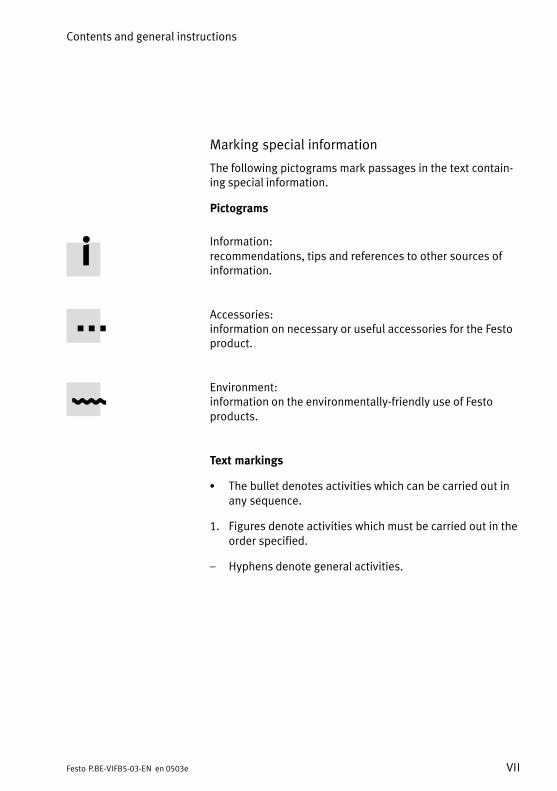
Marking special information
The following pictograms mark passages in the text containing special information.
Pictograms
Information:recommendations, tips and references to other sources ofinformation.
Accessories:information on necessary or useful accessories for the Festoproduct.
Environment:information on the environmentally−friendly use of Festoproducts.
Text markings
S The bullet denotes activities which can be carried out inany sequence.
1. Figures denote activities which must be carried out in theorder specified.
Hyphens denote general activities.

Contents and general instructions
VIII Festo P.BE−VIFB5−03−EN en 0503e
Abbreviations
The following product−specific abbreviations are used in thismanual:
Abbreviation Meaning
Terminal or valve terminal Valve terminal type 03 or type 04−B with or without electric I/Os
Node Field bus node/control unit
Sub−base
Single solenoid sub−base
Double solenoid sub−base
Type 03:Pneumatic sub−base for two valvesType 04−BManifold sub−base with Intermediate solenoid plate MUH and pneumatic valve with hole pattern as per ISO 5599−2 size 1, 2 or 3 incl.
Sub−base for single−solenoid valves
Sub−base for double−solenoid valves or mid−position valves
IOI/O
InputOutputInput and/or output
P−module General pneumatic module
I/O module Module with digital inputs or outputs in general
PLC Programmable logic controller; in brief: controller
FO Fibre−optical waveguide
Fig.0/1: Index of abbreviations
Contents and general instructions
IXFesto P.BE−VIFB5−03−EN en 0503e
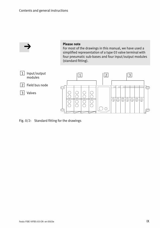
Please noteFor most of the drawings in this manual, we have used asimplified representation of a type 03 valve terminal withfour pneumatic sub−bases and four input/output modules(standard fitting).
1 Input/outputmodules
2 Field bus node
3 Valves
1 2 3
Fig.0/2: Standard fitting for the drawings

Contents and general instructions
X Festo P.BE−VIFB5−03−EN en 0503e
Manuals for this valve terminal
Depending on your order and on the equipment to be fittedon your system, you will require the following Festo manualsfor the complete documentation of the modular valve terminal:
Festo designation Title/product
P.BE−MIDI/MAXI−03−... Pneumatics manual Valve terminal type 03, MIDI/MAXI
P.BE−VIISO−04−B−... Pneumatics manual Valve terminal type 04−B, ISO 5599−2
P.BE−VIEA−03/04B−.. Supplementary manual for the I/O modules (digital I/O modules 4I, 8I, 4O, high−current output modules, multi I/O modules)
P.BE−VIEA−03/04B−.. Analogue I/O manual
P.BE−VIEA−03/04B−.. Electronics manual FB5 field bus connection (thismanual)
Fig.0/3: Manuals for this valve terminal
Contents and general instructions
XIFesto P.BE−VIFB5−03−EN en 0503e
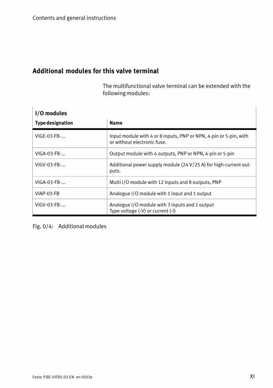
Additional modules for this valve terminal
The multifunctional valve terminal can be extended with thefollowing modules:
I/O modules
Type designation Name
VIGE−03−FB−... Input module with 4 or 8 inputs, PNP or NPN, 4−pin or 5−pin, withor without electronic fuse.
VIGA−03−FB−... Output module with 4 outputs, PNP or NPN, 4−pin or 5−pin
VIGV−03−FB−... Additional power supply module (24 V/25 A) for high−current outputs.
VIGA−03−FB−... Multi I/O module with 12 inputs and 8 outputs, PNP
VIAP−03−FB Analogue I/O module with 1 input and 1 output
VIGV−03−FB−... Analogue I/O module with 3 inputs and 1 outputType voltage (−V) or current (−I)
Fig.0/4: Additional modules
Contents and general instructions
XII Festo P.BE−VIFB5−03−EN en 0503e
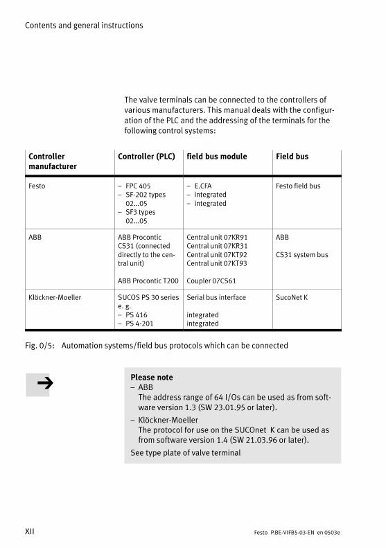
The valve terminals can be connected to the controllers ofvarious manufacturers. This manual deals with the configur
ation of the PLC and the addressing of the terminals for thefollowing control systems:
Controller manufacturer
Controller (PLC) field bus module Field bus
Festo FPC 405 SF−202 types
02...05 SF3 types
02...05
E.CFA integrated integrated
Festo field bus
ABB ABB ProconticCS31 (connecteddirectly to the central unit)
ABB Procontic T200
Central unit 07KR91Central unit 07KR31Central unit 07KT92Central unit 07KT93
Coupler 07CS61
ABB
CS31 system bus
Klöckner−Moeller SUCOS PS 30 seriese.g. PS 416 PS 4−201
Serial bus interface
integratedintegrated
SucoNet K
Fig.0/5: Automation systems/field bus protocols which can be connected
Please note ABB The address range of 64 I/Os can be used as from software version 1.3 (SW 23.01.95 or later).
Klöckner−Moeller The protocol for use on the SUCOnet K can be used asfrom software version 1.4 (SW 21.03.96 or later).
See type plate of valve terminal

Summary of components
1−1Festo P.BE−VIFB5−03−EN en 0503e
Chapter 1
1. Summary of components
1−2 Festo P.BE−VIFB5−03−EN en 0503e
Contents
1.1 Summary of multifunctional Festo valve terminals 1−3. . . . . . . . . . . . . . . . . . . .
1.2 Description of components 1−4. . . . . . . . . . . . . . . . . . . . . . . . . . . . . . . . . . . . . . .
1.2.1 Types 03/04−B electric modules 1−4. . . . . . . . . . . . . . . . . . . . . . . . . . . . . . . . . . .
1.2.2 Type 03: MIDI pneumatic modules 1−5. . . . . . . . . . . . . . . . . . . . . . . . . . . . . . . . .
1.2.3 Type 03: MAXI pneumatic modules 1−6. . . . . . . . . . . . . . . . . . . . . . . . . . . . . . . . .
1.2.4 Type 04−B ISO pneumatic modules 1−7. . . . . . . . . . . . . . . . . . . . . . . . . . . . . . . . .
1.3 Method of operation 1−8. . . . . . . . . . . . . . . . . . . . . . . . . . . . . . . . . . . . . . . . . . . .
1. Summary of components
1−3Festo P.BE−VIFB5−03−EN en 0503e
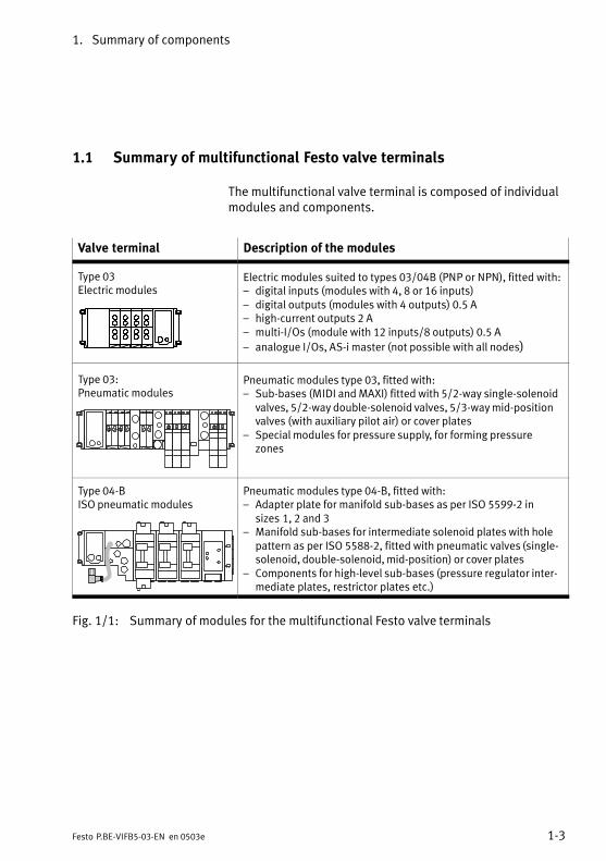
1.1 Summary of multifunctional Festo valve terminals
The multifunctional valve terminal is composed of individualmodules and components.
Valve terminal Description of the modules
Type 03 Electric modules
Electric modules suited to types 03/04B (PNP or NPN), fitted with: digital inputs (modules with 4, 8 or 16 inputs) digital outputs (modules with 4 outputs) 0.5 A high−current outputs 2 A multi−I/Os (module with 12 inputs/8 outputs) 0.5 A
analogue I/Os, AS−i master (not possible with all nodes)
Type 03:Pneumatic modules
Pneumatic modules type 03, fitted with: Sub−bases (MIDI and MAXI) fitted with 5/2−way single−solenoid
valves, 5/2−way double−solenoid valves, 5/3−way mid−positionvalves (with auxiliary pilot air) or cover plates
Special modules for pressure supply, for forming pressurezones
Type 04−BISO pneumatic modules
Pneumatic modules type 04−B, fitted with: Adapter plate for manifold sub−bases as per ISO 5599−2 in
sizes1, 2 and 3 Manifold sub−bases for intermediate solenoid plates with hole
pattern as per ISO 5588−2, fitted with pneumatic valves (single−solenoid, double−solenoid, mid−position) or cover plates
Components for high−level sub−bases (pressure regulator intermediate plates, restrictor plates etc.)
Fig.1/1: Summary of modules for the multifunctional Festo valve terminals

1. Summary of components
1−4 Festo P.BE−VIFB5−03−EN en 0503e
1.2 Description of components
1.2.1 Types 03/04−B: Electric modules
The following connecting and display elements can be foundon the electric modules:
1
2 3 4 5 6 7
89
1 Input socket for two electric inputs(PNP or NPN)
2 Red LED (error display per input module with electronic fuse)
3 Two green LEDs (one LED per input)
4 Input socket for one electric input(PNP or NPN)
5 Green LED (per input)
6 Output socket for electric output (PNP)
7 Yellow LED (status display per output)
8 Red LED (error display per output)
9 Further modules (e.g. additional powersupply, high−current outputs PNP/NPN)
Fig.1/2: Connecting and display elements on the electric modules
1. Summary of components
1−5Festo P.BE−VIFB5−03−EN en 0503e
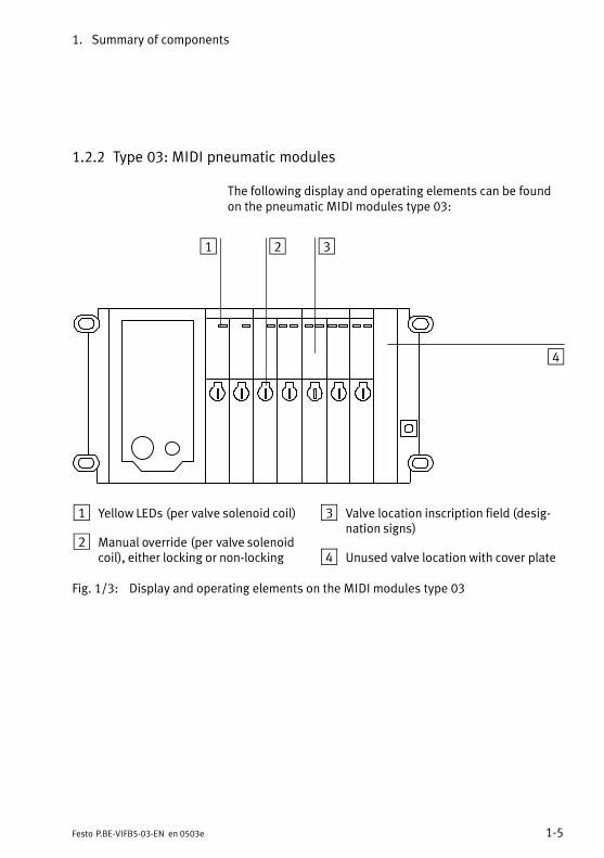
1.2.2 Type 03: MIDI pneumatic modules
The following display and operating elements can be foundon the pneumatic MIDI modules type03:
1 2 3
4
1 Yellow LEDs (per valve solenoid coil)
2 Manual override (per valve solenoidcoil), either locking or non−locking
3 Valve location inscription field (designation signs)
4 Unused valve location with cover plate
Fig.1/3: Display and operating elements on the MIDI modules type 03
1. Summary of components
1−6 Festo P.BE−VIFB5−03−EN en 0503e
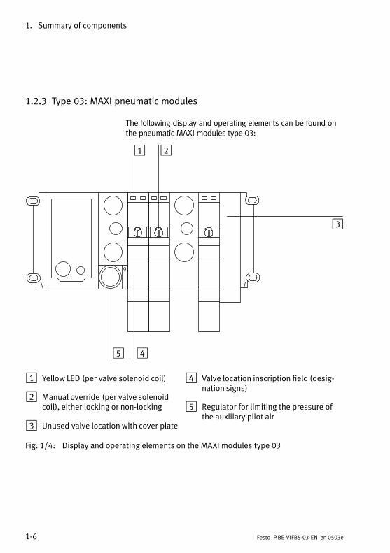
1.2.3 Type 03: MAXI pneumatic modules
The following display and operating elements can be found onthe pneumatic MAXI modules type 03:
1 2
3
45
1 Yellow LED (per valve solenoid coil)
2 Manual override (pervalve solenoidcoil), either locking or non−locking
3 Unused valve location with cover plate
4 Valve location inscription field (designation signs)
5 Regulator for limiting the pressure ofthe auxiliary pilot air
Fig.1/4: Display and operating elements on the MAXI modules type 03
1. Summary of components
1−7Festo P.BE−VIFB5−03−EN en 0503e
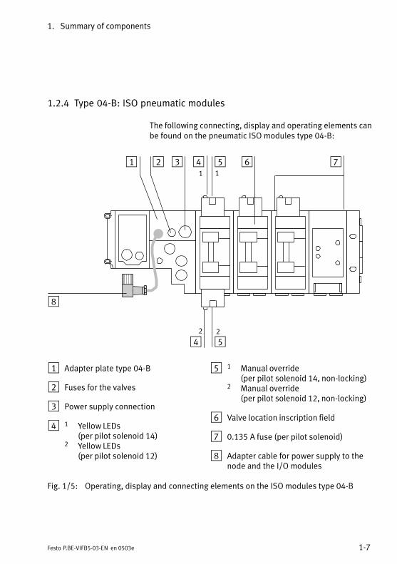
1.2.4 Type 04−B: ISO pneumatic modules
The following connecting, display and operating elements canbe found on the pneumatic ISO modules type04−B:
1 2 3 4 5 6 7
4 5
8
1 1
2 2
1 Adapter plate type 04−B
2 Fuses for the valves
3 Power supply connection
4 1 Yellow LEDs(per pilot solenoid 14)
2 Yellow LEDs (per pilot solenoid 12)
5 1 Manual override (per pilot solenoid 14, non−locking)
2 Manual override(per pilot solenoid 12, non−locking)
6 Valve location inscription field
7 0.135A fuse (perpilot solenoid)
8 Adapter cable for power supply to thenode and the I/O modules
Fig.1/5: Operating, display and connecting elements on the ISO modules type 04−B
1. Summary of components
1−8 Festo P.BE−VIFB5−03−EN en 0503e
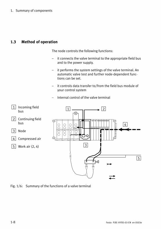
1.3 Method of operation
The node controls the following functions:
it connects the valve terminal to the appropriate field busand to the power supply.
it performs the system settings of the valve terminal. Anautomatic valve test and further node−dependent functions can be set.
it controls data transfer to/from the field bus module ofyour control system
Internal control of the valve terminal
1 Incoming fieldbus
2 Continuing fieldbus
3 Node
4 Compressed air
5 Work air (2, 4)
1 2
3
4
5
ÏÏ
ÏÏ
Fig.1/6: Summary of the functions of a valve terminal
1. Summary of components
1−9Festo P.BE−VIFB5−03−EN en 0503e
The input modules process input signals (e.g. from sensors)and transmit these signals via the field bus to the controller.
The output modules are universal electric outputs and controllow−current consuming devices with positive logic, e.g.further valves, bulbs, etc.).
Additional I/O modules for special applications are also available.
Further information on the use of all I/O modules can be foundin the "Supplementary description of the I/O modules" for yourvalve terminal.
The pneumatic modules perform the following functions:
they form the common channels for supply and exhaustair
they supply electric signals from all the valve solenoidcoils
Work connections 2 and 4 are provided for each valve location on the individual pneumatic modules.
The valves are supplied with compressed air via the commonchannels on the pneumatic end plate or via special supplymodules. The exhaust air and pilot exhaust are also ventedvia these channels/modules. Further modules for pressuresupply are also available, e.g. for working with different pressures or for fitting either MIDI/MAXI valves or ISO valves on anode.
Further information on their use can be found in the "Pneumatics manual" for your valve terminal.
1. Summary of components
1−10 Festo P.BE−VIFB5−03−EN en 0503e
Fitting
2−1Festo P.BE−VIFB5−03−EN en 0503e
Chapter 2
2. Fitting
2−2 Festo P.BE−VIFB5−03−EN en 0503e
Contents
2.1 Fitting the modules and components 2−3. . . . . . . . . . . . . . . . . . . . . . . . . . . . . . .
2.1.1 Earthing the end plates 2−4. . . . . . . . . . . . . . . . . . . . . . . . . . . . . . . . . . . . . . . . . .
2.2 Fitting onto a hat rail (type 03) 2−6. . . . . . . . . . . . . . . . . . . . . . . . . . . . . . . . . . . .
2.3 Fitting the valve terminal onto a wall 2−9. . . . . . . . . . . . . . . . . . . . . . . . . . . . . . .
2. Fitting
2−3Festo P.BE−VIFB5−03−EN en 0503e
2.1 Fitting the modules and components
The valve terminal is supplied from the factory ready fitted. Ifyou wish to supplement or replace individual modules orcomponents, please follow the instructions in the followingmanuals:
Supplementary description of the I/O modules" for fitting the electric I/O modules
Pneumatics manual" for fitting the pneumatic modules
Fitting instructions supplied with the product in the caseof modules and components ordered at a later date.
Please noteHandle all modules and components of the valve terminalwith the utmost care. Pay particular attention to the following:
Make sure that screws are not distorted and not subjected to mechanical stress. Make sure that screws arecorrectly aligned (otherwise their threads may be damaged).
Make sure that the specified torques are not exceeded.
Avoid misalignment between the modules (IP 65).
Make sure that connecting surfaces are clean (avoidleakage and contact faults).
The contacts of type 03 valve solenoid coils must not bebent (they are not resistant to bending, i.e. they willbreak off if bent backwards).
Electrostatically sensitive components Do not touch the contact surfaces of the plug connectorson the sides of the modules and components.

2. Fitting
2−4 Festo P.BE−VIFB5−03−EN en 0503e
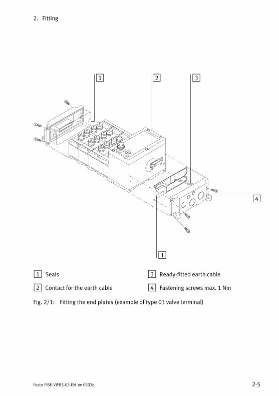
2.1.1 Earthing the end plates
The valve terminal possesses both a left−hand and a right−hand end plate as a mechanical termination of the valve terminal. These end plates fulfil the following requirements:
they comply with protection class IP 65.
they contain connections/contacts for earthing.
they contain holes for fitting the valve terminal onto a walland, in the case of type03, also for the hat−rail clampingunit.
Please noteWhen supplied from the factory, the end plates of the valveterminal are earthed internally. If you wish to extend/convert the type 03 valve terminal, earth the end plates of thevalve terminal as described below.
You thereby avoid faults caused by electromagnetic influences.
Earth the end plates after extension/conversion as follows:
1. Right−hand end plate (type 03):In order to earth the right−hand end plate, connect theready−fitted cable on the inside to the appropriate contacts on the pneumatic modules or on the node (seediagram below).
2. Left−hand end plate:The left−hand end plate is connected conductively to theother components by means of the ready−fitted springcontacts.
Remark:Instructions on earthing the complete valve terminal can befound in the chapter Installation".The diagram below shows how the end plates are fitted usingas an example a type 03 valve terminal.
2. Fitting
2−5Festo P.BE−VIFB5−03−EN en 0503e
1 2 3
4
1
1 Seals
2 Contact for the earth cable
3 Ready−fitted earth cable
4 Fastening screws max.1Nm
Fig.2/1: Fitting the end plates (example of type 03 valve terminal)
2. Fitting
2−6 Festo P.BE−VIFB5−03−EN en 0503e
2.2 Fitting onto a hat rail (type 03)
The valve terminal is suitable for fitting onto a hat rail (support rail as per EN 50022). For this purpose there is a guidegroove on the rear of all modules in order that they can behung on a hat rail (see Fig. 2/3).
Caution Fitting the valve terminal onto a hat rail without a hat−railclamping unit is not permitted.
If the valve terminal is fitted in a sloping position or if itis subject to vibration, secure the hat−rail clamping unitadditionally:− against sliding down and use the locking screws (item3) to protect it against unintentional loosening/opening.
Please note If the valve terminal is fitted in a horizontal position andif the load is at rest, the hat−rail clamping unit can beused without locking screws (item 3).
If you do not have a hat−rail clamping unit for your valveterminal, you can order this and fit it at a later stage.
The use of MIDI or MAXI clamping units depends on theend plates available (MIDI/MAXI).
Hat−rail clamping unit (type 03)
In order to fit the valve terminal onto a hat rail, you will require a hat−rail clamping unit. This must be fitted on the rearof the end plates as shown in the diagram below. Pay particular attention to the following:
2. Fitting
2−7Festo P.BE−VIFB5−03−EN en 0503e
Before fitting:
S Make sure that the surfaces for glueing on the rubber feetare clean (cleaned with spirit).
S Make sure that the flat−head screws (item 3) are tightened.
After fitting:
S Fasten the lever with a locking screw (item 7).
2
3
4
5
6
1
1
1 Lever*)
2 O−ring
3 Flat−head screw
4 Self−adhesive rubber foot
5 Clamping elements
6 Locking screw
*) Different lever lengths with MIDI and MAXI
Fig.2/2: Fitting the hat−rail clamping unit
2. Fitting
2−8 Festo P.BE−VIFB5−03−EN en 0503e
Proceed as follows:
1. Ascertain the weight of your valve terminal as describedin chapter 2.3
2. Make sure that the mounting surface can support thisweight.
3. Fit a hat rail (support rail as per EN 50022 − 35x15;width35 mm, height 15 mm).
4. Fasten the hat rail to the fastening surface at least every100mm.
5. Hang the valve terminal onto the hat rail. Fasten the valveterminal on both sides with the hat−rail clamping unit toprevent it from tilting or sliding (see Fig.2/3).
6. If the hat−rail clamping unit is subject to vibration or if it isfitted in a sloping position, fasten it with two lockingscrews (item 3) against unintentional loosening/opening.
1 Hat−rail clampingunit unlocked
2 Hat−rail clampingunit locked
3 Locking screw
1 3 32
Fig.2/3: Fitting the type 03 valve terminal to a hat rail
2. Fitting
2−9Festo P.BE−VIFB5−03−EN en 0503e
2.3 Fitting the valve terminal onto a wall
CautionIn the case of long valve terminals with several I/O modules, use additional support brackets for the modules (approximately every 200 mm). You can thereby avoid:
overloading the fastening eyes on the left−hand endplate
the terminal sagging (I/O side)
natural resonance
Proceed as follows:
1. Ascertain the weight of your valve terminal (weigh orcalculate). Reference values:
Valve terminal module
type 03 *)
− per pneumatic module (incl. valves)MIDI0.8 kg
MAXI1.2 kg
Type 04−B manifold sub−bases*)
Adapter plate and right−hand endplate
per pneumatic module (incl. manifoldsub−base, intermediate solenoidplate and valve)
ISO size 13.0 kg
1.2 kg
ISO size 23.2 kg
1.6 kg
ISO size 34.1 kg
2.4 kg
Node 1 kg 1 kg 1 kg
I/O module 0.4 kg 0.4 kg 0.4 kg
*) Components for high−level linking: Weight see Pneumatics manual
2. Make sure that the mounting surface can support thisweight. Check to see if you require support brackets forthe I/O modules.
3. If necessary, use spacers.

2. Fitting
2−10 Festo P.BE−VIFB5−03−EN en 0503e
4. Fasten the valve terminal, depending on the type, asshown in the following table. The valve terminal can befitted in any desired position.
Type of valve terminal Fastening methods
Type 03 with four M6 screws on the left−hand andright−hand end plate.
In the case of valve terminals with several I/Omodules, use additional support brackets for themodules (approximately every 200 mm).
Type 04−B with two M6 screws on the left−hand end plate with three M6 screws (ISO sizes 1 and 2) or
M8 (ISO size 3) on the adapter plate and onthe right−hand end plate.
If required, use the following additional methodsof fastening: a fastening screw per manifold sub−base the hole on the bottom of the manifold sub−
base (blind hole", see Pneumatics manual) In the case of valve terminals with several I/O
modules, use additional support brackets forthe modules (approximately every 200 mm).
Fig.2/4: Possibilities for fitting onto a wall

Installation
3−1Festo P.BE−VIFB5−03−EN en 0503e
Chapter 3
3. Installation
3−2 Festo P.BE−VIFB5−03−EN en 0503e
Contents
3.1 General connection methods 3−3. . . . . . . . . . . . . . . . . . . . . . . . . . . . . . . . . . . . . .
3.1.1 Selecting the field bus cable 3−4. . . . . . . . . . . . . . . . . . . . . . . . . . . . . . . . . . . . . .
3.1.2 Selecting the operating voltage cable 3−6. . . . . . . . . . . . . . . . . . . . . . . . . . . . . . .
3.2 Field bus node 3−7. . . . . . . . . . . . . . . . . . . . . . . . . . . . . . . . . . . . . . . . . . . . . . . . .
3.2.1 Opening and closing the node 3−7. . . . . . . . . . . . . . . . . . . . . . . . . . . . . . . . . . . . .
3.2.2 Configuring the valve terminal 3−9. . . . . . . . . . . . . . . . . . . . . . . . . . . . . . . . . . . . .
3.2.3 Setting the field bus address 3−10. . . . . . . . . . . . . . . . . . . . . . . . . . . . . . . . . . . . . .
3.2.4 Setting the field bus baud rate 3−13. . . . . . . . . . . . . . . . . . . . . . . . . . . . . . . . . . . .
3.2.5 Setting the field bus protocol 3−14. . . . . . . . . . . . . . . . . . . . . . . . . . . . . . . . . . . . .
3.3 Switching on the power supply 3−15. . . . . . . . . . . . . . . . . . . . . . . . . . . . . . . . . . . .
3.3.1 Calculating the current consumption 3−16. . . . . . . . . . . . . . . . . . . . . . . . . . . . . . .
3.3.2 Connecting the power supply 3−18. . . . . . . . . . . . . . . . . . . . . . . . . . . . . . . . . . . . .
3.4 Connecting the field bus interface 3−23. . . . . . . . . . . . . . . . . . . . . . . . . . . . . . . . . .
3.4.1 Connection instructions for Festo and ABB 3−26. . . . . . . . . . . . . . . . . . . . . . . . . .
3.4.2 Connection instructions for Klöckner−Moeller 3−27. . . . . . . . . . . . . . . . . . . . . . . .
3.4.3 Terminating resistor 3−28. . . . . . . . . . . . . . . . . . . . . . . . . . . . . . . . . . . . . . . . . . . . .
3. Installation
3−3Festo P.BE−VIFB5−03−EN en 0503e
3.1 General connection methods
WarningSwitch off the following before undertaking installationand/or maintenance work:
the compressed air supply
the operating voltage supply for the electronics (pin 1)
the load voltage supply for the outputs/valves (pin 2).
You can thereby avoid:
sudden uncontrolled movements of loose tubing
unexpected movements of the connected actuators
non−defined switching states of the electronic components.
3. Installation
3−4 Festo P.BE−VIFB5−03−EN en 0503e
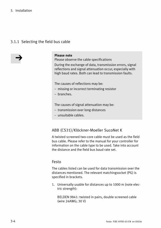
3.1.1 Selecting the field bus cable
Please notePlease observe the cable specifications
During the exchange of data, transmission errors, signalreflections and signal attenuation occur, especially withhigh baud rates. Both can lead to transmission faults.
The causes of reflections may be:
missing or incorrect terminating resistor
branches.
The causes of signal attenuation may be:
transmission over long distances
unsuitable cables.
ABB (CS31)/Klöckner−Moeller SucoNet K
A twisted screened two−core cable must be used as the field
bus cable. Please refer to the manual for your controller forinformation on the cable type to be used. Take into accountthe distance and the field bus baud rate set.
Festo
The cables listed can be used for data transmission over the
distances mentioned. The relevant matchingsocket (PG) isspecified in brackets.
1. Universally usable for distances up to 1000 m (note electric strength):
BELDEN 9841: twisted in pairs, double screened cable(wire 24AWG; 30 V)
3. Installation
3−5Festo P.BE−VIFB5−03−EN en 0503e
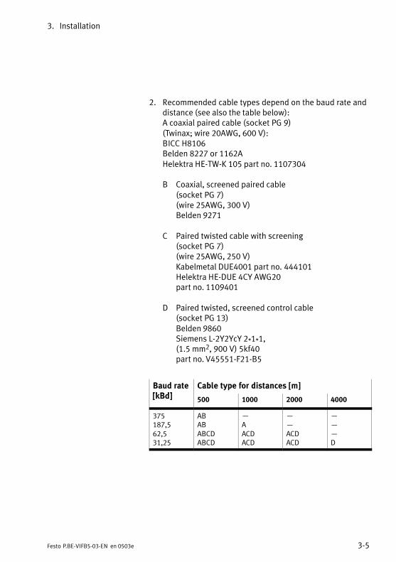
2. Recommended cable types depend on the baud rate anddistance (see also the table below):A coaxial paired cable (socket PG 9)(Twinax; wire 20AWG, 600 V): BICC H8106 Belden 8227 or 1162AHelektra HE−TW−K 105 part no. 1107304
B Coaxial, screened paired cable (socket PG 7)(wire 25AWG, 300 V)Belden 9271
C Paired twisted cable with screening (socket PG 7)(wire 25AWG, 250 V)Kabelmetal DUE4001 part no. 444101 Helektra HE−DUE 4CY AWG20part no. 1109401
D Paired twisted, screened control cable (socket PG 13)Belden 9860Siemens L−2Y2YcY 2*1*1, (1.5 mm2, 900 V) 5kf40part no. V45551−F21−B5
Baud rate[kBd]
Cable type for distances [m][kBd] 500 1000 2000 4000
375187,562,531,25
ABABABCDABCD
AACDACD
ACDACD
D
3. Installation
3−6 Festo P.BE−VIFB5−03−EN en 0503e
Available from
BICC Deutschland GmbHDüsseldorfer Str. 18641460 Neuss
Belden Electronics GmbH
Fuggerstr. 241468 Neuss
Helektra GmbHBoschweg 12−1612057 Berlin 44
kabelmetal electro GmbH
Schafhofstr. 3590411 Nürnberg
Siemens AGUB NKKistlerhofstr. 170
81379 München 70
3.1.2 Selecting the operating voltage cable
Several parameters must be taken into consideration whenthe operating voltages are connected. Further informationcan be found in the following chapters:
Chapter 3.4: Installation section Connecting the
power supply "− calculating the current consumption − design of the power unit
− cable cross section and length (orientation values)
Appendix A.2: Cable length and cross−sectional area
− determining the cross−sectional area and length by means of tables − calculating with a formula.
3. Installation
3−7Festo P.BE−VIFB5−03−EN en 0503e
3.2 Field bus node
3.2.1 Opening and closing the node
WarningSwitch off the following before undertaking installationand/or maintenance work:
S the compressed air supply
S the operating voltage supply for the electronics (pin 1)
S the operating voltage supply for the outputs/valves(pin2).
You can thereby avoid:
sudden uncontrolled movements of loose tubing
unexpected movements of the connected actuators
non−defined switching states of the electronic components.
Please noteThe node contains electrostatically sensitive components.
S Do not therefore touch any contacts.
S Please observe the regulations for handling electrostatically sensitive components.
You can thereby prevent the electronics of the node frombeing damaged.
3. Installation
3−8 Festo P.BE−VIFB5−03−EN en 0503e
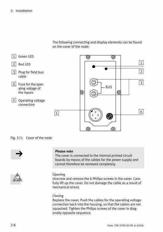
The following connecting and display elements can be foundon the cover of the node:
1 Green LED
2 Red LED
3 Plug for field buscable
4 Fuse for the operating voltage ofthe inputs
5 Operating voltageconnection
BUS
1
2
3
45
Fig.3/1: Cover of the node
Please noteThe cover is connected to the internal printed circuitboards by means of the cables for the power supply andcannot therefore be removed completely.
OpeningUnscrew and remove the 6 Philips screws in the cover. Carefully lift up the cover. Do not damage the cable as a result ofmechanical stress.
ClosingReplace the cover. Push the cables for the operating voltageconnection back into the housing, so that the cables are notsquashed. Tighten the Philips screws of the cover in diagonally opposite sequence.

3. Installation
3−9Festo P.BE−VIFB5−03−EN en 0503e
3.2.2 Configuring the valve terminal
There are four printed circuit boards in the node. There is anLED and two plugs for the field bus cables on board 2; on
board 3 there is an LED and switches for setting the configuration.
1 Green LED
2 Red LED
3 Address selectorswitch(station no.)
4 DIL switches
5 Board 4
6 Board 3
7 Flat plug for theoperating voltageconnection
8 Board 2
9 Screening plate
aJ Board 1
aA Plug for field buscable
3
4
5
6
7
8
9
aJ
aA
1
2
Fig.3/2: Connecting, display and operating elements on the node

3. Installation
3−10 Festo P.BE−VIFB5−03−EN en 0503e
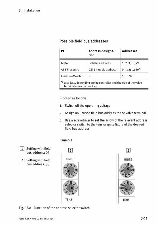
3.2.3 Setting the field bus address
You can set the field bus address of the valve terminal withthe two address selector switches on board 3. The switches
are numbered from 0...9. The arrow on the address selectorswitches shows the tens or units figure of the field bus address set.
1 Address selectorswitch for UNITSfigure
2 Address selectorswitch for TENSfigure
1
2
Fig.3/3: Address selector switch
Please noteField bus addresses may only be assigned once per fieldbus module.
Recommendation:Assign the field bus addresses in ascending order. Assign thefield bus addresses, if necessary, to suit the machine structure of your system.
3. Installation
3−11Festo P.BE−VIFB5−03−EN en 0503e
Possible field bus addresses
PLC Address designation
Addresses
Festo Field bus address 1; 2; 3; ...; 99
ABB Procontic CS31 module address 0; 1; 2; ...; 60*)
Klöckner−Moeller − 1; ...; 99
*) also less, depending on the controller and the size of the valve terminal (see chapter 4.4)
Proceed as follows:
1. Switch off the operating voltage.
2. Assign an unused field bus address to the valve terminal.
3. Use a screwdriver to set the arrow of the relevant addressselector switch to the tens or units figure of the desiredfield bus address.
Example
1 Setting with fieldbus address: 05
2 Setting with fieldbus address: 38
1 2
UNITS
TENS
UNITS
TENS
Fig.3/4: Function of the address selector switch
3. Installation
3−12 Festo P.BE−VIFB5−03−EN en 0503e
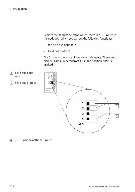
Besides the address selector switch, there is a DIL switch inthe node with which you can set the following functions:
the field bus baud rate
Field bus protocol.
The DIL switch consists of four switch elements. These switch
elements are numbered from 1...4. The position "ON" ismarked.
1 Field bus baudrate
2 Field bus protocol
1
2
Fig.3/5: Position of the DIL switch
3. Installation
3−13Festo P.BE−VIFB5−03−EN en 0503e
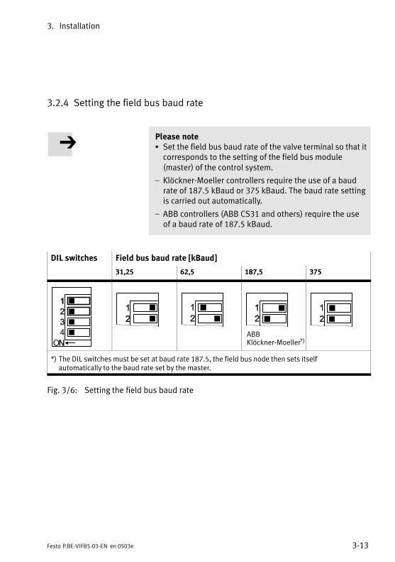
3.2.4 Setting the field bus baud rate
Please noteS Set the field bus baud rate of the valve terminal so that itcorresponds to the setting of the field bus module(master) of the control system.
Klöckner−Moeller controllers require the use of a baudrate of 187.5 kBaud or 375kBaud. The baud rate settingis carried out automatically.
ABB controllers (ABB CS31 and others) require the useof a baud rate of 187.5 kBaud.
DIL switches Field bus baud rate [kBaud]
31,25 62,5 187,5 375
ABBKlöckner−Moeller*)
*) The DIL switches must be set at baud rate 187.5, the field bus node then sets itselfautomatically to the baud rate set by the master.
Fig.3/6: Setting the field bus baud rate
3. Installation
3−14 Festo P.BE−VIFB5−03−EN en 0503e
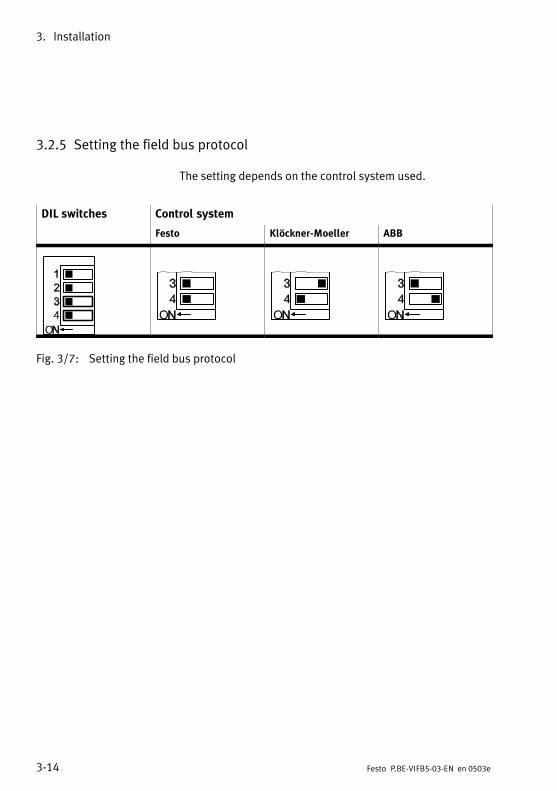
3.2.5 Setting the field bus protocol
The setting depends on the control system used.
DIL switches Control system
Festo Klöckner−Moeller ABB
Fig.3/7: Setting the field bus protocol
3. Installation
3−15Festo P.BE−VIFB5−03−EN en 0503e
3.3 Switching on the power supply
WarningS Use only PELV circuits as per IEC/DIN EN 60204−1 (Protective Extra−Low Voltage, PELV) for the electrical supply.Consider also the general requirements for PELV circuitsin accordance with IEC/DIN EN 60204−1.
S Use power supplies which guarantee reliable electricalisolation of the operating voltage as per IEC/DIN EN60204−1.
By the use of PELV circuits, protection against electric shock(protection against direct and indirect contact) is guaranteedin accordance with IEC/EN 60204−1 (Electrical equipment formachines, General requirements).
CautionThe load voltage supply for the outputs/valves must befused externally with maximum 10 A (slow blowing). Withthe external fuse you can avoid functional damage to thevalve terminal in the event of a short circuit.
3. Installation
3−16 Festo P.BE−VIFB5−03−EN en 0503e
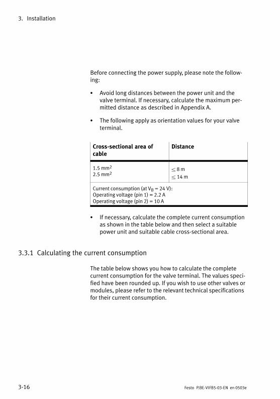
Before connecting the power supply, please note the following:
S Avoid long distances between the power unit and thevalve terminal. If necessary, calculate the maximum permitted distance as described in Appendix A.
S The following apply as orientation values for your valveterminal.
Cross−sectional area ofcable
Distance
1.5 mm2
2.5 mm2 8 m
14 m
Current consumption (at VB = 24 V):Operating voltage (pin 1) = 2.2 AOperating voltage (pin 2) = 10 A
S If necessary, calculate the complete current consumptionas shown in the table below and then select a suitablepower unit and suitable cable cross−sectional area.
3.3.1 Calculating the current consumption
The table below shows you how to calculate the completecurrent consumption for the valve terminal. The values specified have been rounded up. If you wish to use other valves ormodules, please refer to the relevant technical specificationsfor their current consumption.
3. Installation
3−17Festo P.BE−VIFB5−03−EN en 0503e
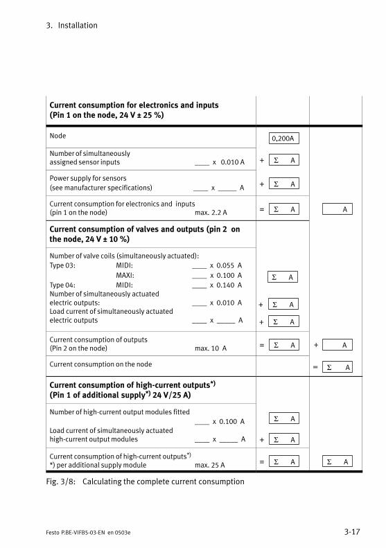
Current consumption for electronics and inputs (Pin 1 on the node, 24 V ± 25 %)
Node 0,200A
Number of simultaneouslyassigned sensor inputs ____ x 0.010 A + Σ A
Power supply for sensors
(see manufacturer specifications) ____ x _____ A + Σ A
Current consumption for electronics and inputs (pin 1 on the node) max.2.2 A = Σ A A
Current consumption of valves and outputs (pin2 onthe node, 24 V ± 10 %)
Number of valve coils (simultaneously actuated):
Type 03: MIDI: ____ x 0.055 A MAXI: ____ x 0.100 A
Type 04: MIDI: ____ x 0.140 A Number of simultaneously actuated electric outputs: ____ x 0.010 ALoad current of simultaneously actuated electric outputs ____ x _____ A
Σ A
+ Σ A
+ Σ A
Current consumption of outputs (Pin 2 on the node) max. 10 A = Σ A A+
Current consumption on the node = Σ A
Current consumption of high−current outputs*) (Pin 1 of additional supply*) 24 V/25 A)
Number of high−current output modules fitted
____ x 0.100 A Load current of simultaneously actuatedhigh−current output modules ____ x _____ A
Σ A
+ Σ A
Current consumption of high−current outputs*)
*) per additional supply module max. 25 A = Σ A Σ A
Fig.3/8: Calculating the complete current consumption
3. Installation
3−18 Festo P.BE−VIFB5−03−EN en 0503e
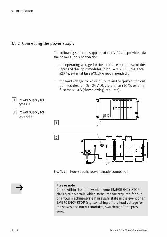
3.3.2 Connecting the power supply
The following separate supplies of +24V DC are provided viathe power supply connection:
the operating voltage for the internal electronics and theinputs of the input modules (pin 1: +24 V DC, tolerance±25%, external fuse M3.15A recommended).
the load voltage for valve outputs and outputs of the output modules (pin 2: +24 V DC, tolerance ±10%, externalfuse max. 10 A (slow blowing) required).
1 Power supply fortype 03
2 Power supply fortype 04B
ÓÓÓÓÓ
1
2
Fig.3/9: Type−specific power supply connection
Please noteCheck within the framework of your EMERGENCY STOPcircuit, to ascertain which measures are required for putting your machine/system in a safe state in the event of anEMERGENCY STOP (e.g. switching off the load voltage forthe valves and output modules, switching off the pressure).

3. Installation
3−19Festo P.BE−VIFB5−03−EN en 0503e
The pin assignments of the power supply connection on thenode (type 03) and on the adapter block (type 04−B) areidentical.
1 24V supply forelectronics andinputs
2 24V load voltagesupply for valvesand outputs
3 0V
4 Earthconnection
1
2
3
4
Fig.3/10: Pin assignment of the power supply connection for types 03/04−B
Please noteCommon operating and load voltage supplies for pin 1(electronics and inputs) and pin 2 (outputs/valves):
S In this case, note that the lower tolerance of ±10% forboth current circuits must be observed.
Check the 24V load voltage of the outputs while your systemis operating. Make sure that the load voltage of the outputslies within the permitted tolerance even during operation atfull load.
Recommendation:Use a closed−loop power unit.
3. Installation
3−20 Festo P.BE−VIFB5−03−EN en 0503e
Potential equalization
The valve terminal has two earth connections for potentialequalization.
on the load voltage connection (pin 4 incoming socket).
on the left−hand end plate (M4 thread).
Please noteS Always connect the earth potential to pin 4 of the voltage connection.
S Connect the earth connection of the left−hand end plateto the earth potential with low impedance (short cablewith large cross−sectional area).
S By means of low−impedance connections, you can besure that the housing of the valve terminal and the earthconnection at pin 4 have the same potential and thatthere are no equalizingcurrents.
You can thereby avoid interference due to electromagneticinfluences and you can ensure electromagnetic compatibility in accordance with the EMC guidelines.

3. Installation
3−21Festo P.BE−VIFB5−03−EN en 0503e
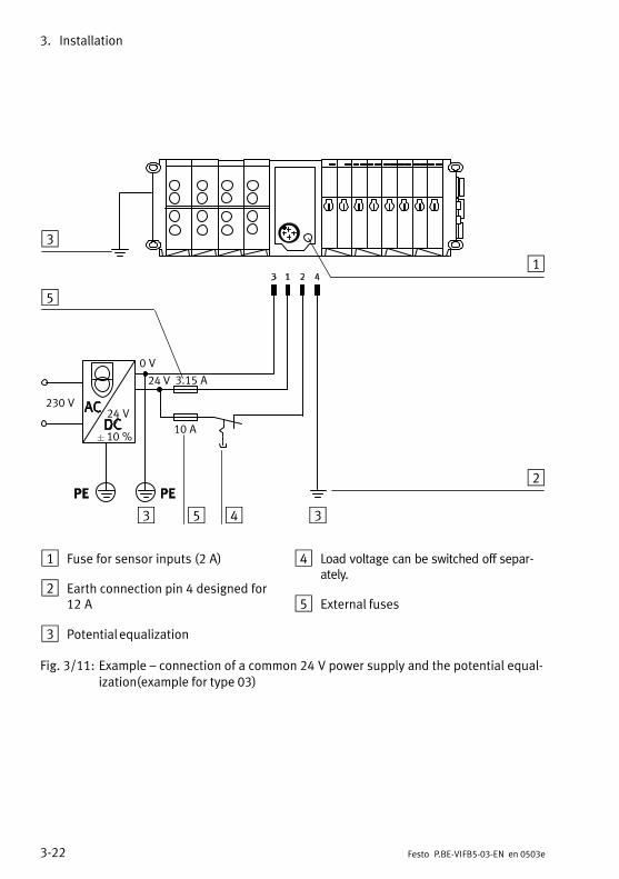
Example of connection
The diagram below shows as an example the connection of acommon 24V power supply for pin 1 and pin 2. Please notehere that:
the load voltage supply for the outputs/valves must beprotected with an external fuse of maximum 10A (slowblowing) against short circuit/overload.
the power supply for the electronics and the inputsshould be protected with an external fuse of 3.15 Aagainst short circuit/overload (recommendation).
the power supply for the sensors is also protected withthe fuse fitted (2 A).
the common tolerance of 24 V DC 10 % must be observed.
both connections are connected for potential equalizationand that equalizing currents are avoided.
the load voltage at pin 2 (valves/electric outputs) can beswitched off separately.
3. Installation
3−22 Festo P.BE−VIFB5−03−EN en 0503e
0V
3.15A
10A
230V
10%
24V
1
2
34
5
3
24 V
5
3
1 Fuse for sensor inputs (2A)
2 Earth connection pin 4 designed for12A
3 Potential equalization
4 Load voltage can be switched off separately.
5 External fuses
Fig.3/11: Example connection of a common 24V power supply and the potential equalization(example for type 03)
3. Installation
3−23Festo P.BE−VIFB5−03−EN en 0503e
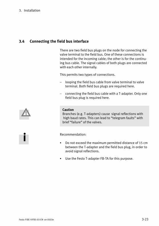
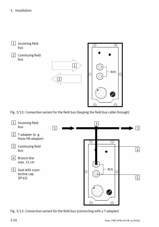
3.4 Connecting the field bus interface
There are two field bus plugs on the node for connecting thevalve terminal to the field bus. One of these connections is
intended for the incoming cable; the other is for the continuing bus cable. The signal cables of both plugs are connectedwith each other internally.
This permits two types of connections.
looping the field bus cable from valve terminal to valveterminal. Both field bus plugs are required here.
connecting the field bus cable with a T−adapter. Only onefield bus plug is required here.
CautionBranches (e.g. T−adapters) cause signal reflections withhigh baud rates. This can lead to telegram faults" withbrief failure" of the valves.
Recommendation:
S Do not exceed the maximum permitted distance of 15 cmbetween the T−adapter and the field bus plug, in order toavoid signal reflections.
S Use the Festo T−adapter FB−TA for this purpose.
3. Installation
3−24 Festo P.BE−VIFB5−03−EN en 0503e
1 Incoming fieldbus
2 Continuing fieldbus
1
2
BUS
Fig.3/12: Connection variant for the field bus (looping the field bus cable through)
1 Incoming fieldbus
2 T−adapter (e.g.Festo FB−adapter)
3 Continuing fieldbus
4 Branch linemax.15cm
5 Seal with a protective cap(IP65)
BUS
12
3
4
5
Fig.3/13: Connection variant for the field bus (connecting with a T−adapter)
3. Installation
3−25Festo P.BE−VIFB5−03−EN en 0503e
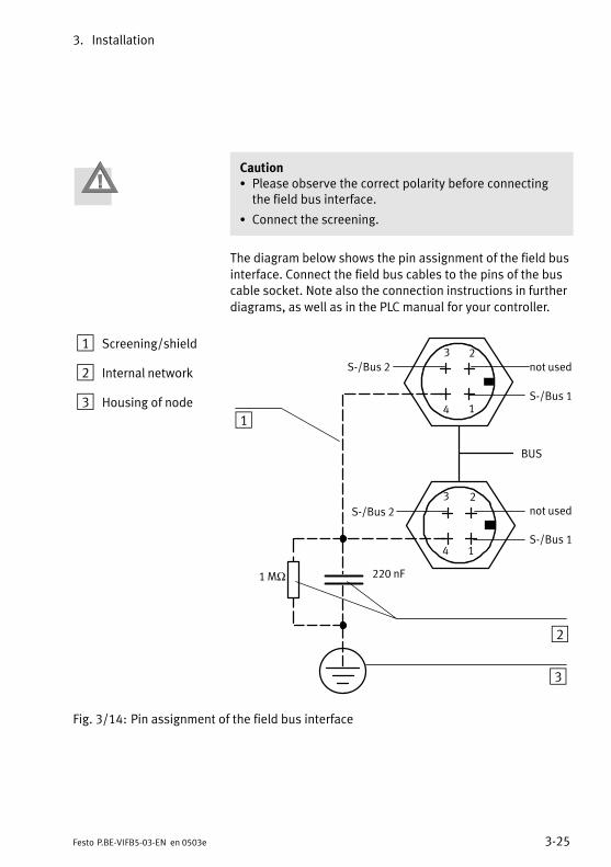
CautionS Please observe the correct polarity before connectingthe field bus interface.
S Connect the screening.
The diagram below shows the pin assignment of the field bus
interface. Connect the field bus cables to the pins of the buscable socket. Note also the connection instructions in further
diagrams, as well as in the PLC manual for your controller.
1 Screening/shield
2 Internal network
3 Housing of node
BUS
1
23
4
1
23
4
1 MΩ 220 nF
1
2
3
S−/Bus 2 not used
S−/Bus 1
S−/Bus 2 not used
S−/Bus 1
Fig.3/14: Pin assignment of the field bus interface
3. Installation
3−26 Festo P.BE−VIFB5−03−EN en 0503e
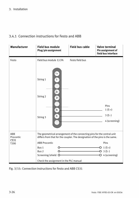
3.4.1 Connection instructions for Festo and ABB
Manufacturer Field bus modulePlug/pin assignment
Field bus cable Valve terminalPin assignment offield bus interface
Festo Field bus module E.CFA Festo field bus
String 1
String 2
String 3
Pins
1 (S +)
3 (S −)
4 (screening)
ABBProconticCS31
The geometrical arrangement of the connecting pins for the central unitdiffers from that for the coupler. The designation of the pins is the same.
CS31T200 ABB Procontic
Bus 1
Screening/shield
Pins
Bus 2
1 (S +)
3 (S −)
4 (screening)
Check the assignment in the PLC manual
Fig.3/15: Connection instructions for Festo and ABB CS31
3. Installation
3−27Festo P.BE−VIFB5−03−EN en 0503e
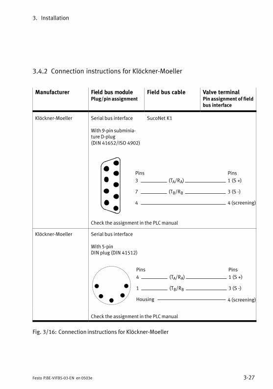
3.4.2 Connection instructions for Klöckner−Moeller
Manufacturer Field bus modulePlug/pin assignment
Field bus cable Valve terminalPin assignment of fieldbus interface
Klöckner−Moeller Serial bus interface
With 9−pin subminiature D−plug(DIN41652/ISO4902)
SucoNet K1
Pins
1 (S +)
3 (S −)
4 (screening)
Pins
3
7
4
(TA/RA)
(TB/RB
Check the assignment in the PLC manual
Klöckner−Moeller Serial bus interface
With 5−pinDIN plug (DIN 41512)
Pins
1 (S +)
3 (S −)
4 (screening)
Pins
4
1
Housing
(TA/RA)
(TB/RB
Check the assignment in the PLC manual
Fig.3/16: Connection instructions for Klöckner−Moeller
3. Installation
3−28 Festo P.BE−VIFB5−03−EN en 0503e
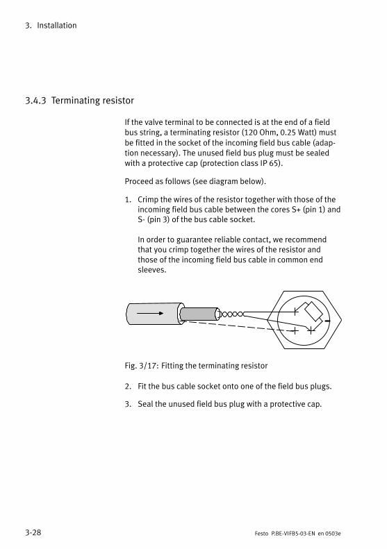
3.4.3 Terminating resistor
If the valve terminal to be connected is at the end of a fieldbus string, a terminating resistor (120 Ohm, 0.25 Watt) must
be fitted in the socket of the incoming field bus cable (adaption necessary). The unused field bus plug must be sealedwith a protective cap (protection class IP 65).
Proceed as follows (see diagram below).
1. Crimp the wires of the resistor together with those of theincoming field bus cable between the cores S+ (pin 1) andS− (pin 3) of the bus cable socket.
In order to guarantee reliable contact, we recommendthat you crimp together the wires of the resistor andthose of the incoming field bus cable in common endsleeves.
Fig.3/17: Fitting the terminating resistor
2. Fit the bus cable socket onto one of the field bus plugs.
3. Seal the unused field bus plug with a protective cap.

Commissioning
4−1Festo P.BE−VIFB5−03−EN en 0503e
Chapter 4
4. Commissioning
4−2 Festo P.BE−VIFB5−03−EN en 0503e
Contents
4.1 Addressing and configuring the valve terminal 4−3. . . . . . . . . . . . . . . . . . . . . . .
4.1.1 Ascertaining the configuration data 4−3. . . . . . . . . . . . . . . . . . . . . . . . . . . . . . . .
4.1.2 Address assignment of the valve terminal 4−6. . . . . . . . . . . . . . . . . . . . . . . . . . .
4.1.3 Address assignment after extension/conversion 4−11. . . . . . . . . . . . . . . . . . . . . .
4.2 General commissioning instructions 4−13. . . . . . . . . . . . . . . . . . . . . . . . . . . . . . . .
4.2.1 Switching on the power supply 4−14. . . . . . . . . . . . . . . . . . . . . . . . . . . . . . . . . . . .
4.3 Commissioning the Festo field bus 4−15. . . . . . . . . . . . . . . . . . . . . . . . . . . . . . . . .
4.3.1 Configuration 4−15. . . . . . . . . . . . . . . . . . . . . . . . . . . . . . . . . . . . . . . . . . . . . . . . . .
4.3.2 Addressing 4−17. . . . . . . . . . . . . . . . . . . . . . . . . . . . . . . . . . . . . . . . . . . . . . . . . . . .
4.4 Commissioning the ABB CS31 4−20. . . . . . . . . . . . . . . . . . . . . . . . . . . . . . . . . . . . .
4.4.1 General information 4−20. . . . . . . . . . . . . . . . . . . . . . . . . . . . . . . . . . . . . . . . . . . . .
4.4.2 CS31 central unit as bus master 4−22. . . . . . . . . . . . . . . . . . . . . . . . . . . . . . . . . . .
4.4.3 T200 / 07CS61 as bus master 4−24. . . . . . . . . . . . . . . . . . . . . . . . . . . . . . . . . . . . .
4.4.4 T200 / 07CS61 as bus master 4−26. . . . . . . . . . . . . . . . . . . . . . . . . . . . . . . . . . . . .
4.4.5 Transmission times 4−28. . . . . . . . . . . . . . . . . . . . . . . . . . . . . . . . . . . . . . . . . . . . . .
4.5 Commissioning Klöckner−Moeller 4−29. . . . . . . . . . . . . . . . . . . . . . . . . . . . . . . . . .
4.5.1 Configuration 4−29. . . . . . . . . . . . . . . . . . . . . . . . . . . . . . . . . . . . . . . . . . . . . . . . . .
4.5.2 Addressing Klöckner−Moeller 4−30. . . . . . . . . . . . . . . . . . . . . . . . . . . . . . . . . . . . . .
4. Commissioning
4−3Festo P.BE−VIFB5−03−EN en 0503e
4.1 Addressing and configuring the valve terminal
4.1.1 Ascertaining the configuration data
Before configuring, ascertain the exact number of availableinputs/outputs. A multifunctional valve terminal consists of avarying number of I/Os, depending on what you haveordered.
Please noteS The status bits must be treated like inputs and occupyfour additional input addresses.
S The maximum possible extension of the valve terminal islimited by the addressing limits of the relevant field busprotocol and the mechanical limits of the valve terminal.
S Type 04−BWith this valve terminal, the assignment of the valveaddresses can be set fixed by means of a DIL switch inthe adapter block. This manual valve terminal configuration (Address reserving") is described in the Appendixof the Pneumatics manual for type 04−B.

4. Commissioning
4−4 Festo P.BE−VIFB5−03−EN en 0503e
The table below shows the number of I/Os required per module for configuration.
Type of module Number of I/Osassigned*)
MIDI/MAXI manifold (type 03) Single solenoid sub−base Double solenoid sub−base
ISO manifold (type 04−B) Single solenoid sub−base Double solenoid sub−base
4−output module (4 digital outputs)
4−input module (4 digital inputs)
8−input module (8 digital inputs)
16−input module (16 digital inputs)Multi I/O module
Status bits**)
2A4A
1A2A
4A
4E
8E
16E
12E + 8A
4E
*) The I/Os are assigned automatically within the valve terminal,irrespective of whether an input/output is actually used.
**) The status bits are assigned automatically within the terminal,as soon as there are input modules.
Fig.4/1: Number of assigned I/Os per module
Copy the following table for further calculations.

4. Commissioning
4−5Festo P.BE−VIFB5−03−EN en 0503e
Calculating the number of inputs/outputs
Inputs
1. Number of 4−input modules ________ x 4
2. Number of 8−input modules ________ x 8
3. Number of 16−input modules ________ x 16
4. Number of other inputs, e.g. multi I/O module
5. The 4 status bits are assigned internally automatically by the valve terminal.
Σ E
+ Σ E
Σ E
+
Σ E+
+ 4 E
Total number of inputs to be configured = Σ E
Outputs
6. Number of single−solenoid sub−bases MIDI/MAXI ________ x 2
7. Number of double−solenoid sub−bases MIDI/MAXI ________ x 4
8. Number of type 04−B single−solenoid sub−bases*) ________ x 1
9. Number of type 04−B double−solenoid sub−bases*) ________ x 2
+ Σ A
+ Σ A
+ Σ A
Σ A
*) Note the possible address reservations with type 04−B
Intermediate sum 6.9.10.Check to see if the sum of 6. 9.
is divisible by four without remainder. This check is necessary because of the 4−bit−orientated internal addressing of the terminal. The following distinction is made: a) if divisible by four without remainder: continue with point 11.b) If not: round up to the next half byte (+1...3).
11.Number of 4−output electric modules ________ x 4
12.Number of other outputs, e.g. multi I/O module
= Σ A
+ 2 A
+ Σ A
+ Σ A
Total number of outputs to be configured = Σ A
4. Commissioning
4−6 Festo P.BE−VIFB5−03−EN en 0503e
4.1.2 Address assignment of the valve terminal
The address assignment of the outputs of a multifunctionalvalve terminal depends on the equipment fitted on the valveterminal. A distinction is made between the following equipment fitted:
valves and digital I/O modules.
only valves.
only digital I/O modules.
The basic rules described below apply to the address assignment of these fitting variants. A detailed example is givenafter each of these basic rules.
Please noteIf two addresses are assigned for one valve location, thefollowing assignment applies:
lower−value address: pilot solenoid 14
higher−value address: pilot solenoid 12
Information on reserving addresses of the valves on the type04−B valve terminal can be found in the Pneumatics manualfor type 04−B.
4. Commissioning
4−7Festo P.BE−VIFB5−03−EN en 0503e
Basic rules of addressing
With mixed fitting, the address assignment of the valves, digital I/O modules and status bits is taken into account.
Outputs
1. The address assignment of the outputs does not dependon the inputs.
2. Address assignment of the valves: Assign the addresses in ascending order without gaps. Counting begins on the node from left to right. Maximum 26 valve solenoid coils can be addressed.
Type 03: Single−solenoid sub−bases always occupy 2 addresses Double−solenoid sub−bases always occupy
4addresses
Type 04−B Single−solenoid sub−bases always occupy 1 address Double−solenoid sub−bases always occupy
2addresses
3. Round up to 4 bits: The following distinction is made: a) If the number of valve addresses can be divided by 4
without remainder, continue with point 4. b) If the number of valve addresses cannot be divided by 4
without remainder, you must round up to 4 bits becauseof the 4−bit orientated addressing. The bits thus rounded up in the address range cannot be used.
4. Commissioning
4−8 Festo P.BE−VIFB5−03−EN en 0503e
4. Address assignment of the output modules:After the (4−bit rounded) addresses of the valvesthe digital outputs must be addressed. Assign the addresses in ascending order without gaps. Counting begins on the node from right to left. Counting on the individual modules is made from the
top to the bottom. Digital output modules occupy 4 or 8 addresses.
Inputs
1. The address assignment of the inputs does not depend onthe outputs.
2. Address assignment of the input modules: Assign the addresses in ascending order without gaps. Counting begins on the node from right to left. On the individual modules from the top to the bottom. Input modules occupy 4, 8, 12 or 16 addresses.
3. Status bits:The address assignment of the status bits depends on thefitting variants of the inputs and the configuration.
The following always applies: The status bits are only available if input modules
are connected to the valve terminal and are configured Addressing
The status bits are transmitted to the four highest−value positions of the configured address range.

4. Commissioning
4−9Festo P.BE−VIFB5−03−EN en 0503e
When the power supply is switched on, the valve terminalautomatically recognizes all available pneumatic modulesand digital input/output modules and assigns the appropriate addresses. If a valve location is not used (cover plate) or ifan input/output is not connected, the relevant address willstill be assigned. The diagram below shows the address assignment as an example.
1 2 3 4 5 6
1 4−input module
2 8−input module
3 4−output module
4 Single sub−base
5 Double sub−base
6 Round up
Fig.4/2: Address assignment of a valve terminal with digital I/Os (example type 03)
Remarks on the diagram
If single−solenoid valves are fitted onto double−solenoidsub−bases of valve terminal type 03 (MIDI/MAXI), fouraddresses will be reserved for valve solenoid coils; thehigher address in each case will then remain unused (seeaddress 3 or Fig.4/1).
if unused valve locations are fitted with cover plates, theaddresses will still be assigned (see addresses 12, 13).
4. Commissioning
4−10 Festo P.BE−VIFB5−03−EN en 0503e
Due to the 4−bit orientated addressing of the modularvalve terminal, rounding up to the full four bits is alwaysmade on the last valve location (if the fitting does not already use the full four bits). This means that two addresses cannot perhaps be used (see addresses 14, 15).
Additional notes on valve terminals without I/O modules
If only valves are used, the address assignment will always beas described in the section Basic rules for addressing".
Please note Maximum 26 valve solenoid coils can be addressed.
The last two locations on the valve side are not roundedup.
Valve terminals without input modules do not require aconfiguration for the inputs. The status bits are nottherefore available.
Additional instructions for valve terminals without valves
If only electric I/Os are used, the address assignment willalways be as described in the section Basic rules for addressing".
Please note Counting begins immediately to the left of the node.
The last two locations on the valve side are not roundedup.
The maximum possible amount of equipment which canbe fitted on the valve terminal is limited by the addressing limits of the relevant field bus protocol and themechanical limits of the valve terminal (max. 96 inputsor 48 outputs).

4. Commissioning
4−11Festo P.BE−VIFB5−03−EN en 0503e
4.1.3 Address assignment after extension/conversion
A special feature of the multifunctional valve terminal is itsflexibility. If the demands made to the machine change, theequipment fitted on the valve terminal can also be changed.
CautionIf the valve terminal is extended or converted at a laterstage, the input/output addresses may be shifted. Thisapplies in the following cases:
when one or several pneumatic sub−bases are added orremoved at a later stage (types 03/04−B).
Type 03: when a pneumatic sub−base for two single−solenoid valves is replaced by a sub−base for twodouble−solenoid valves or vice versa.
Type 04−B when a pneumatic sub−base for one single−solenoid valve is replaced by a sub−base for a double−solenoid valve or vice versa.
when additional input/output modules are added between the node and the existing input/output modules.
when existing input/output modules are removed orreplaced by input/output modules which occupy feweror more input/output addresses.
If the configuration of the inputs is modified, the addresses ofthe status bits may be shifted.
4. Commissioning
4−12 Festo P.BE−VIFB5−03−EN en 0503e
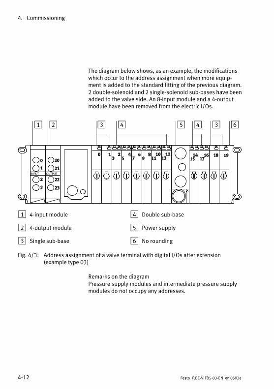
The diagram below shows, as an example, the modificationswhich occur to the address assignment when more equipment is added to the standard fitting of the previous diagram.2 double−solenoid and 2 single−solenoid sub−bases have beenadded to the valve side. An 8−input module and a 4−outputmodule have been removed from the electric I/Os.
1 2 3 4 5 4 3 6
1 4−input module
2 4−output module
3 Single sub−base
4 Double sub−base
5 Power supply
6 No rounding
Fig.4/3: Address assignment of a valve terminal with digital I/Os after extension(example type 03)
Remarks on the diagramPressure supply modules and intermediate pressure supplymodules do not occupy any addresses.
4. Commissioning
4−13Festo P.BE−VIFB5−03−EN en 0503e
4.2 General commissioning instructions
Before commissioning or programming, please compile aconfiguration list of all the connected field bus slaves. On thebasis of this list you can:
carry out a comparison between the NOMINAL and theACTUAL configurations in order to recognize connectionfaults
access these specifications during the syntax check of aprogram in order to avoid addressing errors .
The configuration of the valve terminal requires an accurateprocedure, as in certain circumstances different configurationspecifications are required for each valve terminal on accountof the modular structure. Please observe the instructions forthis procedure in the following sections.
4. Commissioning
4−14 Festo P.BE−VIFB5−03−EN en 0503e
4.2.1 Switching on the power supply
Please notePlease observe also the instructions in the manual for yourcontroller.
When the controller is switched on, it automatically carriesout a comparison between the NOMINAL and the ACTUALconfigurations. For this configuration run it is important that:
the specifications for configuration are complete and correct.
the power supplies for the PLC and the field bus slavesare switched on either simultaneously or in the sequencespecified below.
Please note the following points when switching on the powersupply:
Common supply: If there is a common power supply forthe control system and all the field bus slaves, the powershould be switched on via a central power unit or switch.
Separate supply: If the control system and the field busslaves have separate power supplies, the power shouldbe switched on in the following sequence:
1. the power supply for all the field bus slaves
2. the power supply for the controller.
4. Commissioning
4−15Festo P.BE−VIFB5−03−EN en 0503e
4.3 Commissioning the Festo field bus
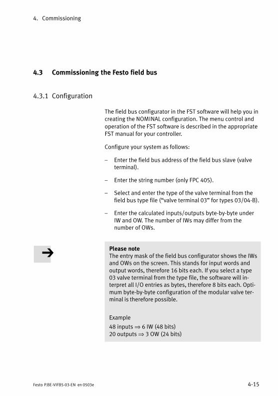
4.3.1 Configuration
The field bus configurator in the FST software will help you increating the NOMINAL configuration. The menu control and
operation of the FST software is described in the appropriateFST manual for your controller.
Configure your system as follows:
Enter the field bus address of the field bus slave (valveterminal).
Enter the string number (only FPC 405).
Select and enter the type of the valve terminal from thefield bus type file (valve terminal 03" for types 03/04−B).
Enter the calculated inputs/outputs byte−by−byte underIW and OW. The number of IWs may differ from thenumber of OWs.
Please noteThe entry mask of the field bus configurator shows the IWsand OWs on the screen. This stands for input words andoutput words, therefore 16 bits each. If you select a type03 valve terminal from the type file, the software will interpret all I/O entries as bytes, therefore 8 bits each. Optimum byte−by−byte configuration of the modular valve terminal is therefore possible.
Example
48 inputs ⇒ 6 IW (48 bits) 20 outputs ⇒ 3 OW (24 bits)
4. Commissioning
4−16 Festo P.BE−VIFB5−03−EN en 0503e
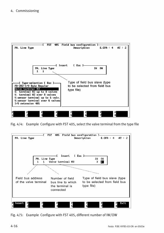
Fig.4/4: Example Configure with FST 405, select the valve terminal from the type file
Fig.4/5: Example Configure with FST 405, different number of IW/OW
4. Commissioning
4−17Festo P.BE−VIFB5−03−EN en 0503e
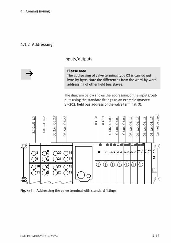
4.3.2 Addressing
Inputs/outputs
Please noteThe addressing of valve terminal type 03 is carried outbyte−by−byte. Note the differences from the word−by−wordaddressing of other field bus slaves.
The diagram below shows the addressing of the inputs/out
puts using the standard fittings as an example (master:SF−202, field bus address of the valve terminal: 3).
I3.1.0...I3.1.3
I3.0.0...I3.0.7
O3.2.4...O3.2.7
O3.2.0...O3.2.3
O3.3.0
O3.3.1
O3.02, O3.0.3
O3.04, O3.0.5
O3.06, O3.0.7
O3.1.0, O3.1.1
O3.1.2, O3.1.3
O3.1.4, O3.1.5
O3.1.6, O3.1.7
(cannot be used)
Fig.4/6: Addressing the valve terminal with standard fittings
4. Commissioning
4−18 Festo P.BE−VIFB5−03−EN en 0503e
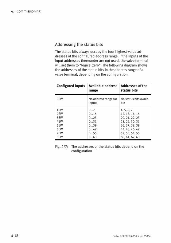
Addressing the status bits
The status bits always occupy the four highest−value addresses of the configured address range. If the inputs of theinput addresses thereunder are not used, the valve terminal
will set them to logical zero". The following diagram showsthe addresses of the status bits in the address range of a
valve terminal, depending on the configuration.
Configured inputs Available addressrange
Addresses of thestatus bits
0EW No address range forinputs
No status bits available
1EW2EW3EW4EW5EW6EW7EW8EW
0...70...150...230...310...390...470...550...63
4, 5, 6, 712, 13, 14, 1520, 21, 22, 2328, 29, 30, 3136, 37, 38, 3944, 45, 46, 4752, 53, 54, 5560, 61, 62, 63
Fig.4/7: The addresses of the status bits depend on theconfiguration
4. Commissioning
4−19Festo P.BE−VIFB5−03−EN en 0503e
Example
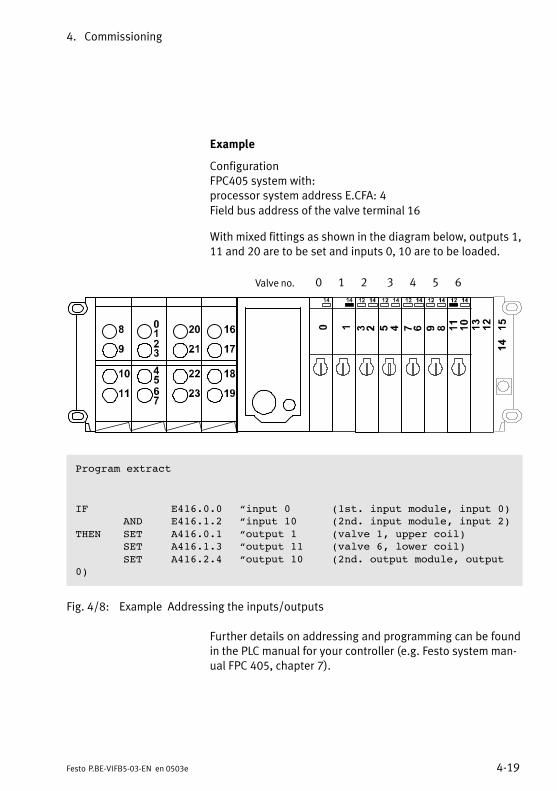
ConfigurationFPC405 system with: processor system address E.CFA: 4
Field bus address of the valve terminal 16
With mixed fittings as shown in the diagram below, outputs 1,11 and 20 are to be set and inputs 0, 10 are to be loaded.
Valve no. 0 1 2 3 4 5 6
Program extract
IF E416.0.0 input 0 (1st. input module, input 0)AND E416.1.2 input 10 (2nd. input module, input 2)
THEN SET A416.0.1 output 1 (valve 1, upper coil)SET A416.1.3 output 11 (valve 6, lower coil)SET A416.2.4 output 10 (2nd. output module, output
0)
Fig.4/8: Example Addressing the inputs/outputs
Further details on addressing and programming can be foundin the PLC manual for your controller (e.g. Festo system manual FPC 405, chapter 7).
4. Commissioning
4−20 Festo P.BE−VIFB5−03−EN en 0503e
4.4 Commissioning the ABB CS31
4.4.1 General information
A valve terminal can be fitted with different numbers of inputsand outputs. This results in the number of bits. See also
chapter Basic principles of configuration and addressing".
The addressing of the valve terminal is based in every case onthe specifications for the CS31 system bus. The followingapplies for the valve terminal:
Every 16 bits require a CS31 bus address. A group of 16which has been started also requires a full CS31 bus address.
The following applies if the CS31 system bus is connected toan ABB Protonic T200.
The address designation of the inputs/outputs is differentfrom that of a CS31 central unit.
The appropriate module identifiers must be entered in theconfiguration table of the T200.
Please noteSelect if possible the range n = 0...58 for the address to be
set in the field bus node. n+3 61 can also be addressedhere.
4. Commissioning
4−21Festo P.BE−VIFB5−03−EN en 0503e
If there are inputs on the valve terminal, 4 additional statusbits will be reserved for diagnostic messages. The status bits
always lie at the upper end of the highest group of 16.
Example Valve terminal with 60 + 4 inputs on the CS31 system bus, setaddress 20, CS31 central unit:
Status bits I 23,12; I 23,13; I 23,14 and I 23,15.
The limits of the valve terminal are:
max. 60 inputs and max. 64 outputs,
max. 26 valve locations (rounded up to groups of 4, these occupy 28 output signals)
only valve terminal type 05 (ISO):max. 12 valve coils may be switched on at the same time.
4. Commissioning
4−22 Festo P.BE−VIFB5−03−EN en 0503e
4.4.2 CS31 central unit as bus master
Summary of addresses
Valve terminal Signal designations when a CS 31 central unit is used
Inputs max. Outputs max. Inputs Outputs
16 O n,00 ... O n,15
32 O n,00 ... O n,15O n+1,00 ... O n+1,15
48 O n,00 ... O n,15O n+1,00 ... O n+1,15O n+2,00 ... O n+2,15
64 O n,00 ... O n,15O n+1,00 ... O n+1,15O n+2,00 ... O n+2,15O n+3,00 ... O n+3,15
12 + 4 I n,00 ... I n,15
28 + 4 I n,00 ... I n,15I n+1,00 ... I n+1,15
44 + 4 I n,00 ... I n,15I n+1,00 ... I n+1,15I n+2,00 ... I n+2,15
60 + 4 I n,00 ... I n,15I n+1,00 ... I n+1,15I n+2,00 ... I n+2,15I n+3,00 ... I n+3,15
12 + 4 16 I n,00 ... I n,15 O n,00 ... O n,15
28 + 4 32 I n,00 ... I n,15I n+1,00 ... I n+1,15
O n,00 ... O n,15O n+1,00 ... O n+1,15
44 + 4 48 I n,00 ... I n,15I n+1,00 ... I n+1,15I n+2,00 ... I n+2,15
O n,00 ... O n,15O n+1,00 ... O n+1,15O n+2,00 ... O n+2,15
60 + 4 64 I n,00 ... I n,15I n+1,00 ... I n+1,15I n+2,00 ... I n+2,15I n+3,00 ... I n+3,15
O n,00 ... O n,15O n+1,00 ... O n+1,15O n+2,00 ... O n+2,15O n+3,00 ... O n+3,15
Fig.4/9: Configuration possibilities and addresses for a CS31 central unit
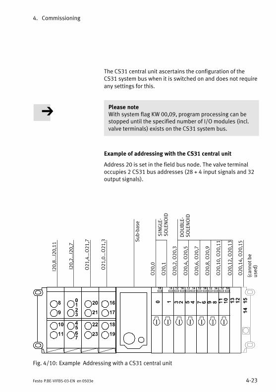
4. Commissioning
4−23Festo P.BE−VIFB5−03−EN en 0503e
The CS31 central unit ascertains the configuration of theCS31 system bus when it is switched on and does not require
any settings for this.
Please noteWith system flag KW 00,09, program processing can bestopped until the specified number of I/O modules (incl.valve terminals) exists on the CS31 system bus.
Example of addressing with the CS31 central unit
Address 20 is set in the field bus node. The valve terminaloccupies 2 CS31 bus addresses (28 + 4 input signals and 32output signals).
I20,8...I20,11
I20,2...I20,7
O21,4...O21,7
O21,0...O21,3
O20,0
O20,1
O20,2, O20,3
O20,4, O20,5
O20,6, O20,7
O20,8, O20,9
O20,10, O20,11
O20,12, O20,13
O20,14, O20,15
(cannot be
used)
SINGLE−
SOLENOID
DOUBLE−
SOLENOID
Sub−base
Fig.4/10: Example Addressing with a CS31 central unit
4. Commissioning
4−24 Festo P.BE−VIFB5−03−EN en 0503e
4.4.3 T200 / 07CS61 as bus master
The T200 station offers the possibility of connecting 4 CS31system busses. The coupler 07CS61 plugged in nearest to the
T200 central unit has line no. 1, the next following have linenumbers 2, 3 and 4.The signal designation I1.20,05 means: line 1, address in the
field bus node 20, input 05.
The max. scope of data for each line is 1024 bits, whereby the
unused bits are also included.
In the example shown below with 12 + 4 inputs and 24 out
puts a total of 64 bits are assigned.
When the program is created, the central unit must be informed how the lines are configured. With the 07 PC 332 programming system, enter here the appropriate module ident
ifiers in the configuration table (see examples).

4. Commissioning
4−25Festo P.BE−VIFB5−03−EN en 0503e
Examples Module identifiers
The configuration list shown applies to line 1.
Valve terminals entered:
Address in the field bus node: 2028 + 4 inputs, 32 outputsThe status bits are: I 21,12...I 21,15
Address in the field bus node: 3364 outputs, this valve terminal does not supply any statusbits
Address in the field bus node: 5060 + 4 inputs, 64 outputsThe status bits are: I 53.12...I 53.15
ÓÓÓÓÓÓÓÓÓÓÓÓÓÓÓ
ÓÓÓÓÓÓÓÓÓÓÓÓ
1
1 Permitted configuration identifiers for Festo valve terminals
Fig.4/11: Example Module identifiers
Remark:Other identifiers could also be entered for the same signalnumbers. However, this will result in completely differentsignal addresses.
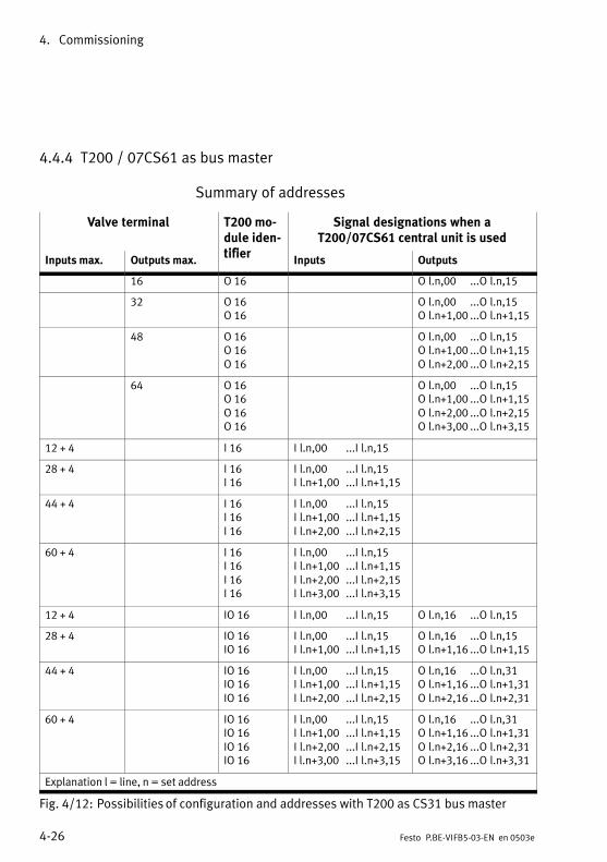
4. Commissioning
4−26 Festo P.BE−VIFB5−03−EN en 0503e
4.4.4 T200 / 07CS61 as bus master
Summary of addresses
Valve terminal T200 module identifier
Signal designations when aT200/07CS61 central unit is used
Inputs max. Outputs max.tifier
Inputs Outputs
16 O 16 Ol.n,00 ...Ol.n,15
32 O 16O 16
Ol.n,00 ...Ol.n,15Ol.n+1,00 ...Ol.n+1,15
48 O 16O 16O 16
Ol.n,00 ...Ol.n,15Ol.n+1,00 ...Ol.n+1,15Ol.n+2,00 ...Ol.n+2,15
64 O 16O 16O 16O 16
Ol.n,00 ...Ol.n,15Ol.n+1,00 ...Ol.n+1,15Ol.n+2,00 ...Ol.n+2,15Ol.n+3,00 ...Ol.n+3,15
12 + 4 I 16 Il.n,00 ...Il.n,15
28 + 4 I 16I 16
Il.n,00 ...Il.n,15Il.n+1,00 ...Il.n+1,15
44 + 4 I 16I 16I 16
Il.n,00 ...Il.n,15Il.n+1,00 ...Il.n+1,15Il.n+2,00 ...Il.n+2,15
60 + 4 I 16I 16I 16I 16
Il.n,00 ...Il.n,15Il.n+1,00 ...Il.n+1,15Il.n+2,00 ...Il.n+2,15Il.n+3,00 ...Il.n+3,15
12 + 4 IO 16 Il.n,00 ...Il.n,15 Ol.n,16 ...Ol.n,15
28 + 4 IO 16IO 16
Il.n,00 ...Il.n,15Il.n+1,00 ...Il.n+1,15
Ol.n,16 ...Ol.n,15Ol.n+1,16 ...Ol.n+1,15
44 + 4 IO 16IO 16IO 16
Il.n,00 ...Il.n,15Il.n+1,00 ...Il.n+1,15Il.n+2,00 ...Il.n+2,15
Ol.n,16 ...Ol.n,31Ol.n+1,16 ...Ol.n+1,31Ol.n+2,16 ...Ol.n+2,31
60 + 4 IO 16IO 16IO 16IO 16
Il.n,00 ...Il.n,15Il.n+1,00 ...Il.n+1,15Il.n+2,00 ...Il.n+2,15I l.n+3,00 ...Il.n+3,15
Ol.n,16 ...Ol.n,31Ol.n+1,16 ...Ol.n+1,31Ol.n+2,16 ...Ol.n+2,31Ol.n+3,16 ...Ol.n+3,31
Explanation l = line, n = set address
Fig.4/12: Possibilities of configuration and addresses with T200 as CS31 bus master
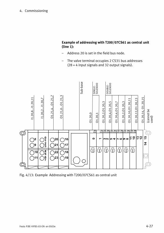
4. Commissioning
4−27Festo P.BE−VIFB5−03−EN en 0503e
Example of addressing with T200/07CS61 as central unit(line 1):
Address 20 is set in the field bus node.
The valve terminal occupies 2 CS31 bus addresses (28 + 4 input signals and 32 output signals).
I1.20,8...I1.20,11
I1.20,2...I1.20,7
O1.21,4...O1.21,7
O1.21,0...O1.21,3
O1.20,0
O1.20,1
O1.20,2,O1.20,3
O1.20,4,O1.20,5
O1.20,6,O1.20,7
O1.20,2,O1.20,3
O1.20,10,O1.20,11
O1.20,12,O1.20,13
O1.20,14, O1.20,15
(cannot be
used)
SINGLE−
SOLE
NOID
DOUBLE−
SOLE
NOID
Sub−base
Fig.4/13: Example Addressing with T200/07CS61 as central unit
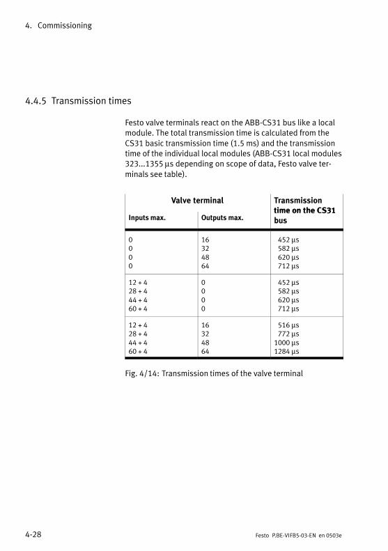
4. Commissioning
4−28 Festo P.BE−VIFB5−03−EN en 0503e
4.4.5 Transmission times
Festo valve terminals react on the ABB−CS31 bus like a localmodule. The total transmission time is calculated from the
CS31 basic transmission time (1.5 ms) and the transmissiontime of the individual local modules (ABB−CS31 local modules323...1355 µs depending on scope of data, Festo valve terminals see table).
Valve terminal Transmissiontime on the CS31
Inputs max. Outputs max.time on the CS31bus
0000
16324864
452 µs582 µs620 µs712 µs
12 + 428 + 444 + 460 + 4
0000
452 µs582 µs620 µs712 µs
12 + 428 + 444 + 460 + 4
16324864
516 µs772 µs1000 µs1284 µs
Fig.4/14: Transmission times of the valve terminal
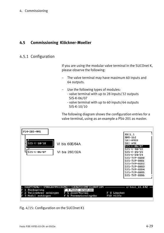
4. Commissioning
4−29Festo P.BE−VIFB5−03−EN en 0503e
4.5 Commissioning Klöckner−Moeller
4.5.1 Configuration
If you are using the modular valve terminal in the SUCOnet K,please observe the following:
The valve terminal may have maximum 60 inputs and64outputs.
Use the following types of modules: − valve terminal with up to 28 inputs/32 outputs SIS−K−06/07− valve terminal with up to 60 inputs/64 outputs SIS−K−10/10
The following diagram shows the configuration entries for a
valve terminal, using as an example a PS4−201 as master.
Fig.4/15: Configuration on the SUCOnet K1

4. Commissioning
4−30 Festo P.BE−VIFB5−03−EN en 0503e
4.5.2 Addressing Klöckner−Moeller
Inputs/outputs
When addressing the inputs/outputs of a valve terminal,please observe the following:
The slave number or the number of the unit differs from the
set station number by −1.
Example
Set field bus address of thevalve terminal
Number of the unit or slavenumber
234..
123..
Fig.4/16: Assignment of units
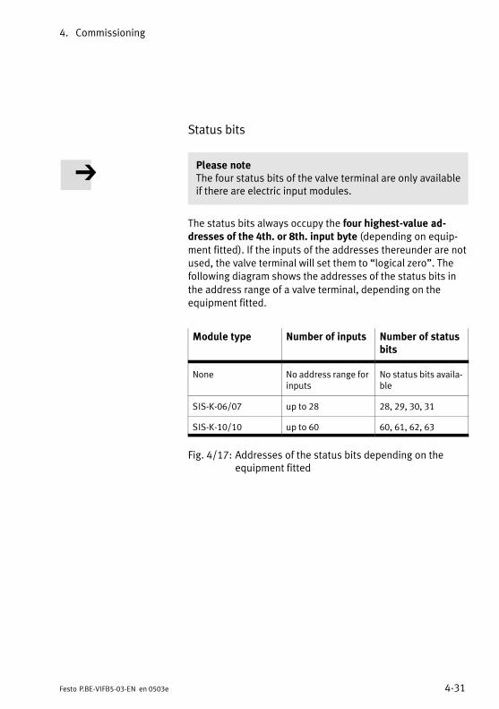
4. Commissioning
4−31Festo P.BE−VIFB5−03−EN en 0503e
Status bits
Please noteThe four status bits of the valve terminal are only availableif there are electric input modules.
The status bits always occupy the four highest−value addresses of the 4th. or 8th. input byte (depending on equipment fitted). If the inputs of the addresses thereunder are notused, the valve terminal will set them to logical zero". Thefollowing diagram shows the addresses of the status bits in
the address range of a valve terminal, depending on theequipment fitted.
Module type Number of inputs Number of statusbits
None No address range forinputs
No status bits available
SIS−K−06/07 up to 28 28, 29, 30, 31
SIS−K−10/10 up to 60 60, 61, 62, 63
Fig.4/17: Addresses of the status bits depending on theequipment fitted
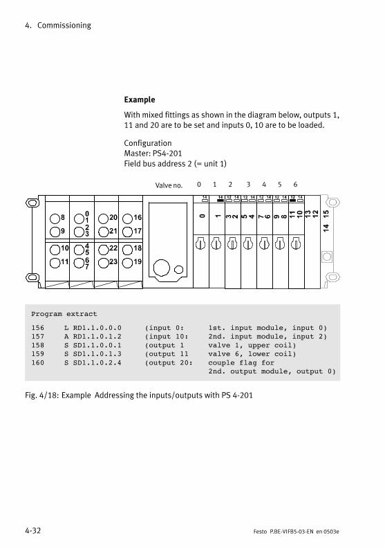
4. Commissioning
4−32 Festo P.BE−VIFB5−03−EN en 0503e
Example
With mixed fittings as shown in the diagram below, outputs 1,11 and 20 are to be set and inputs 0, 10 are to be loaded.
Configuration Master: PS4−201
Field bus address 2 (= unit 1)
Valve no. 0 1 2 3 4 5 6
Program extract
156 L RD1.1.0.0.0 (input 0: 1st. input module, input 0)157 A RD1.1.0.1.2 (input 10: 2nd. input module, input 2)158 S SD1.1.0.0.1 (output 1 valve 1, upper coil)159 S SD1.1.0.1.3 (output 11 valve 6, lower coil)160 S SD1.1.0.2.4 (output 20: couple flag for
2nd. output module, output 0)
Fig.4/18: Example Addressing the inputs/outputs with PS 4−201
Diagnosis and error treatment
5−1Festo P.BE−VIFB5−03−EN en 0503e
Chapter 5
5. Diagnosis and error treatment
5−2 Festo P.BE−VIFB5−03−EN en 0503e
Contents
5.1 Summary of diagnostic possibilities 5−3. . . . . . . . . . . . . . . . . . . . . . . . . . . . . . . .
5.2 On−the−spot diagnosis 5−4. . . . . . . . . . . . . . . . . . . . . . . . . . . . . . . . . . . . . . . . . . .
5.2.1 LEDs on the bus node 5−4. . . . . . . . . . . . . . . . . . . . . . . . . . . . . . . . . . . . . . . . . . .
5.2.2 LEDs of the valves 5−7. . . . . . . . . . . . . . . . . . . . . . . . . . . . . . . . . . . . . . . . . . . . . . .
5.2.3 LEDs of the input/output modules 5−9. . . . . . . . . . . . . . . . . . . . . . . . . . . . . . . . .
5.2.4 Testing the valves 5−11. . . . . . . . . . . . . . . . . . . . . . . . . . . . . . . . . . . . . . . . . . . . . . .
5.3 Status bits 5−14. . . . . . . . . . . . . . . . . . . . . . . . . . . . . . . . . . . . . . . . . . . . . . . . . . . . .
5.3.1 Short circuit/overload 5−16. . . . . . . . . . . . . . . . . . . . . . . . . . . . . . . . . . . . . . . . . . .
5.4 Diagnosis with the field bus 5−17. . . . . . . . . . . . . . . . . . . . . . . . . . . . . . . . . . . . . . .
5.4.1 Diagnostic byte 5−18. . . . . . . . . . . . . . . . . . . . . . . . . . . . . . . . . . . . . . . . . . . . . . . . .
5.4.2 Festo field bus 5−19. . . . . . . . . . . . . . . . . . . . . . . . . . . . . . . . . . . . . . . . . . . . . . . . .
5.4.3 Diagnosis via ABB CS31 5−21. . . . . . . . . . . . . . . . . . . . . . . . . . . . . . . . . . . . . . . . . .
5.4.4 Diagnosis with Klöckner−Moeller SUCOnet K 5−26. . . . . . . . . . . . . . . . . . . . . . . . .
5.4.5 Position of the status bits 5−27. . . . . . . . . . . . . . . . . . . . . . . . . . . . . . . . . . . . . . .
5.5 Error treatment 5−28. . . . . . . . . . . . . . . . . . . . . . . . . . . . . . . . . . . . . . . . . . . . . . . . .
5.6 Type 04−B Fuses for the pilot solenoids 5−29. . . . . . . . . . . . . . . . . . . . . . . . . . . . .
5. Diagnosis and error treatment
5−3Festo P.BE−VIFB5−03−EN en 0503e
5.1 Summary of diagnostic possibilities
The modular valve terminal offers extensive and user−friendlypossibilities of diagnosis and error treatment. The following
possibilities are available depending on the fittings on thevalve terminal.
Valve terminal with inputs
Valve terminal without inputs
Diagnosticpossibilities
Status bits
Bit 27Bit 26Bit 25Bit 24
0XXX1
0011X
0101X
0XXXX
X = not relevant
LEDs Diagnostic byte
None
1234567 0
Vout Vval Vsen None sc/o Cyclep.no.None
Brief description
The four status bits aretransmitted to themodule cyclically asinputs" together withthe normal inputs.
The LEDs showdirectly configuration errors, hardwareerrors, bus errors, etc.
The diagnostic byte must be read outand evaluated user−program controlled.
Advantages fast access to errormessages, irrespectiveof the module and themaster
fast on−the−spot" error recognition
Detailed error recognition, depending onthe field bus protocol
Detailed description
chapter 5.3 chapter 5.2 chapter 5.4
Fig.5/1: Possibilities of diagnosis and error treatment
5. Diagnosis and error treatment
5−4 Festo P.BE−VIFB5−03−EN en 0503e
5.2 On−the−spot diagnosis
5.2.1 LEDs on the bus node
The LEDs on the cover of the node indicate the operatingstatus of the valve terminal.
1 Green LED (operating status display)
2 Red LED (errordisplay)
1
2POWER
ERROR
Fig.5/2: LEDs on the field bus node
The following table explains how the various operating statesare shown by the LEDs.
5. Diagnosis and error treatment
5−5Festo P.BE−VIFB5−03−EN en 0503e
LEDsgreen red
Operating status Error treatment
Operating status normal or:operating status normal but valves donot switch.Possible causes Operating voltage of the outputs
not in tolerance range or not applied.
Compressed air supply not correct. Pilot exhaust blocked.
None
Check the ...S operating voltage connection of the
outputs (pin 2), tolerance range21.6V DC ... 26.4 V)
S the compressed air supplyS pilot exhaust channels
Operating voltage not applied Check the operating voltage connection for the electronics (pin 1)
(very fast)
Baud rate setting and/or address selector switch setting are not permittedwith the field bus protocol set
Check the address/baud rate settings
(1 second i
Field bus connection not correct.Possible causes Address setting is not correct
(e.g. address assigned twice) The baud rates set on the valve ter
minal and on the field bus moduleare not the same.
Field bus protocol setting is not correct
Switched−off or defective field busmodule
Interrupted, short−circuited orfaulty field bus connection
Check the ...
S setting of the address selectorswitch
S baud rate setting on the valve terminal and on the field bus module
S field bus protocol setting
S field bus module
S field bus connection
out flashes redflashes green lights up green lights up red
Fig.5/3: LED display of operating status (part 1)
5. Diagnosis and error treatment
5−6 Festo P.BE−VIFB5−03−EN en 0503e
LEDsgreen red
Operating status Error treatment
(longout)
modules not fitted correctly more than 12 I/O modules fitted This number of I/Os is not sup
ported by the protocol set module type not permitted
Reduce the number of ... I/O modules
Use only permitted module types
Internal faults of the valve terminal Short circuit/overload at an electric
output Vvalves <21.6 V Voutputs <10 V Vsensor < 10 V
S Eliminate the short circuitS or replace the fuseS Check the loading of the power unit
out flashes redflashes green lights up green lights up red
Fig.5/4: LED display of operating status (part 2)
5. Diagnosis and error treatment
5−7Festo P.BE−VIFB5−03−EN en 0503e
5.2.2 LEDs of the valves
There is a yellow LED for each valve solenoid coil on the valveterminal. This shows the switching status of the valve solenoid coil.
Valve terminal type LEDs of the valve solenoid coils
Type 03
Type 04−B
Fig.5/5: Positions of the valve solenoid coil LEDs

5. Diagnosis and error treatment
5−8 Festo P.BE−VIFB5−03−EN en 0503e
LED Switching position of the valvesolenoid coil
Meaning
yellow out basic position logical 0 (no signal)
yellow alight switch positionor basic position
logical 1 (signal present)
logical 1 but operating voltage of outputs lies
below permitted tolerance range(21.6V...26.4V DC)
or compressed air supply not correct.or pilot exhaust blocked.or servicing required
Fig.5/6: LEDs for the status display of the valve solenoid coils
Short circuit/overload (only type 04−B)
The valve solenoid coils of valve terminal type 04−B are fittedwith special fuses for protection against short circuit or overload. The method of replacing these fuses is described inchapter 5.6.
5. Diagnosis and error treatment
5−9Festo P.BE−VIFB5−03−EN en 0503e
5.2.3 LEDs of the input/output modules
Specific explanations on further I/O modules can be found inthe Supplementary description of the I/O modules".
Next to the relevant connections on the input/output modules there are one or two LEDs (status displays) in the colours:
green (status display of the digital inputs).
yellow (status display of the digital outputs).
red (error display of the digital outputs).
The signal currently at the relevant input or output is shownby means of the yellow and green LEDs. The red LEDs of theoutputs display a short circuit/overload at the relevant output.
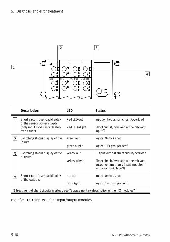
5. Diagnosis and error treatment
5−10 Festo P.BE−VIFB5−03−EN en 0503e
1
2 3
4
Description LED Status
1 Short circuit/overload displayof the sensor power supply(only input modules with electronic fuse)
Red LED out
Red LED alight
Input without short circuit/overload
Short circuit/overload at the relevantinput *)
2 Switching status display of theinputs
green out
green alight
logical 0 (no signal)
logical 1 (signal present)
3 Switching status display of theoutputs
yellow out
yellow alight
Output without short circuit/overload
Short circuit/overload at the relevantoutput or input (only input moduleswith electronic fuse*))
4 Short circuit/overload displayof the outputs
red out
red alight
logical 0 (no signal)
logical 1 (signal present)
*) Treatment of short circuit/overload see Supplementary description of the I/O modules"
Fig.5/7: LED displays of the input/output modules
5. Diagnosis and error treatment
5−11Festo P.BE−VIFB5−03−EN en 0503e
5.2.4 Testing the valves
WarningBefore starting the test, switch off the compressed air supply to the valves.
You can thereby avoid unexpected or dangerous movementsof the actuators.
Caution This test function runs automatically in the valve terminal. All valves will be switched on/off cyclically.
None of the programmed interlockings or further switching conditions will be taken into account.
The valve terminal provides the following test routines with
which all the valves are switched on/off cyclically.
Test routine Meaning
Parallel All valves will be switched on/off cyclically.
Serial All the valves of an address byte will be switchedon/off one after the other at 1 second intervals.
Fig.5/8: Test routines which can be set
5. Diagnosis and error treatment
5−12 Festo P.BE−VIFB5−03−EN en 0503e
Starting the test routine
1. Switch off the operating and load voltage supplies (pins 1and 2).
2. Open the node in accordance with chapter 3.2.1, Opening and closing the node".
3. Note the settings of the address selector switch and theDIL switch elements.
4. Set address 99 and DIL switch elements 1...4 to OFF.
5. Switch on the power supplies (pins 1 and 2).
6. Set the desired test routine on the address selectorswitches as follows:
Test routine Address to be set
Parallel 0, 1 or 2
Serial 3
Fig.5/9: Setting the test routines
7. Start: Set DIL switch elements 1 and 2 to ON.
If faults occur when the test routine is started, the red LED onthe node will flash fast. The procedure must then be repeated.
5. Diagnosis and error treatment
5−13Festo P.BE−VIFB5−03−EN en 0503e
Stopping the test routine
1. Switch off the operating and load voltage supplies to thevalve terminal (pins 1 and 2).
2. Set the address selector switch and the DIL switch elements to their original positions.
Remark:If the yellow LED on the valves does not light up, it may bedue to one of the following causes:
the LED or the solenoid coil is defective.
Only type 04−B:
the internal 0.315A fuse of the manifold sub−base isburnt through (see chapter 5.6).

5. Diagnosis and error treatment
5−14 Festo P.BE−VIFB5−03−EN en 0503e
5.3 Status bits
The valve terminal provides 4 status bits for diagnostic purposes irrespective of the protocol used.
Please noteThe four status bits of the valve terminal are only availablewhen the terminal is equipped with input modules.
The status bits are configured as inputs and always occupythe four highest value addresses in the available addressspace. If the inputs of the addresses underneath these arenot used, the terminal sets them to logic zero".
The position of the 4 status bits within the address space ofthe valve terminal can be found in the following chapters ondiagnosis with the relevant field bus protocol.
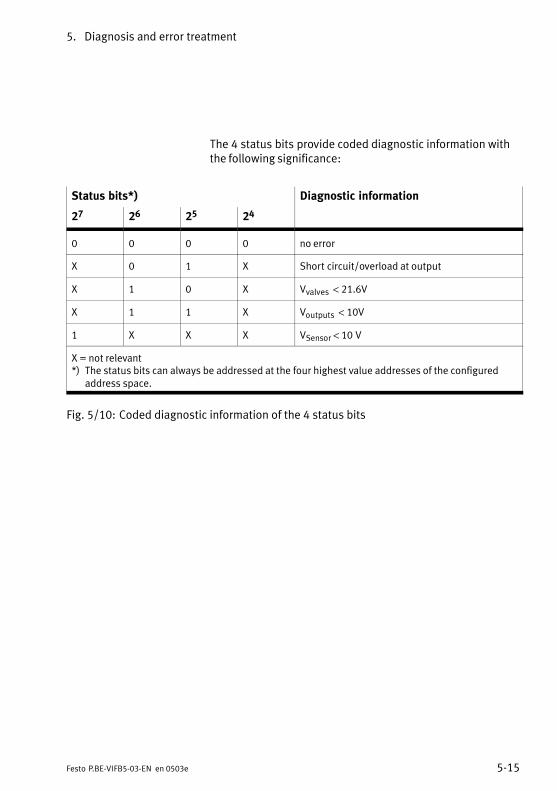
5. Diagnosis and error treatment
5−15Festo P.BE−VIFB5−03−EN en 0503e
The 4 status bits provide coded diagnostic information withthe following significance:
Status bits*) Diagnostic information
27 26 25 24
0 0 0 0 no error
X 0 1 X Short circuit/overload at output
X 1 0 X Vvalves < 21.6V
X 1 1 X Voutputs < 10V
1 X X X VSensor < 10V
X = not relevant*) The status bits can always be addressed at the four highest value addresses of the configured
address space.
Fig.5/10: Coded diagnostic information of the 4 status bits
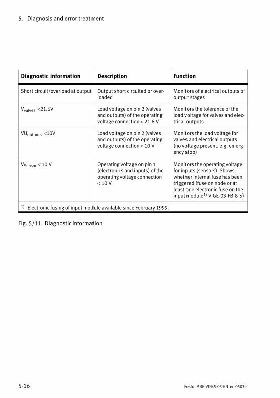
5. Diagnosis and error treatment
5−16 Festo P.BE−VIFB5−03−EN en 0503e
Diagnostic information Description Function
Short circuit/overload at output Output short circuited or overloaded
Monitors of electrical outputs ofoutput stages
Vvalves <21.6V Load voltage on pin 2 (valvesand outputs) of the operatingvoltage connection < 21.6V
Monitors the tolerance of theload voltage for valves and electrical outputs
VUoutputs <10V Load voltage on pin 2 (valvesand outputs) of the operatingvoltage connection < 10V
Monitors the load voltage forvalves and electrical outputs(no voltage present, e.g. emergency stop)
VSensor < 10V Operating voltage on pin 1(electronics and inputs) of theoperating voltage connection<10V
Monitors the operating voltagefor inputs (sensors). Showswhether internal fuse has beentriggered (fuse on node or atleast one electronic fuse on theinput module1) VIGE−03−FB−8−S)
1) Electronic fusing of input module available since February 1999.
Fig.5/11: Diagnostic information
5. Diagnosis and error treatment
5−17Festo P.BE−VIFB5−03−EN en 0503e
5.3.1 Short circuit/overload
During a short circuit or overload, the error code Short circuit/overload" is entered in the 4 status bits of the node.Depending on the field bus protocol used, the terminal provides one or more diagnosis status registers (bytes, words).Most of the field bus protocols can therefore detect andevaluate a short circuit (see Chapter 5.4).
Short circuit/overload at an IO module
Valve terminals type 03 or 04−B can be equipped, amongstothers, with the following IO modules:
Output modules
High−current output modules
Multi−I/O modules
Input modules
Input modules with fuses
The behaviour of these modules during short circuit/overloadis described in the Supplementary description of the I/Omodules".
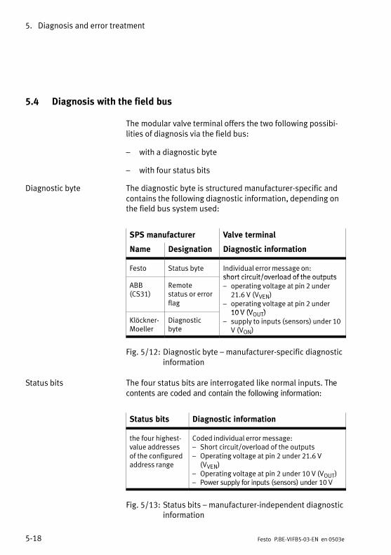
5. Diagnosis and error treatment
5−18 Festo P.BE−VIFB5−03−EN en 0503e
5.4 Diagnosis with the field bus
The modular valve terminal offers the two following possibilities of diagnosis via the field bus:
with a diagnostic byte
with four status bits
Diagnostic byte The diagnostic byte is structured manufacturer−specific andcontains the following diagnostic information, depending onthe field bus system used:
SPS manufacturer Valve terminal
Name Designation Diagnostic information
Festo Status byte Individual error message on:short circuit/overload of the outputs
ABB(CS31)
Remotestatus or errorflag
short circuit/overload of the outputs operating voltage at pin 2 under
21.6V (VVEN) operating voltage at pin 2 under
10 V (V )Klöckner−Moeller
Diagnosticbyte
10V (VOUT) supply to inputs (sensors) under 10
V (VON)
Fig.5/12: Diagnostic byte manufacturer−specific diagnosticinformation
Status bits The four status bits are interrogated like normal inputs. Thecontents are coded and contain the following information:
Status bits Diagnostic information
the four highest−value addressesof the configuredaddress range
Coded individual error message: Short circuit/overload of the outputs Operating voltage at pin 2 under 21.6 V
(VVEN) Operating voltage at pin 2 under 10 V (VOUT) Power supply for inputs (sensors) under 10V
Fig.5/13: Status bits manufacturer−independent diagnosticinformation
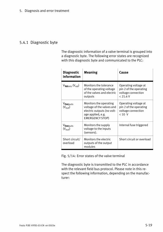
5. Diagnosis and error treatment
5−19Festo P.BE−VIFB5−03−EN en 0503e
5.4.1 Diagnostic byte
The diagnostic information of a valve terminal is grouped intoa diagnostic byte. The following error states are recognized
with this diagnostic byte and communicated to the PLC:
Diagnosticinformation
Meaning Cause
VValves (Vval) Monitors the toleranceof the operating voltageof the valves and electricoutputs
Operating voltage atpin2 of the operatingvoltage connection<21.6 V
VOutputs(Vout)
Monitors the operatingvoltage of the valves andelectric outputs (no voltage applied, e.g.EMERGENCY STOP)
Operating voltage atpin2 of the operatingvoltage connection< 10V
VOutputs(Vout)
Monitors the supplyvoltage to the inputs(sensors).
Internal fuse triggered
Short circuit/overload
Monitors the electricoutputs of the outputmodules
Short circuit or overload
Fig.5/14: Error states of the valve terminal
The diagnostic byte is transmitted to the PLC in accordance
with the relevant field bus protocol. Please note in this respect the following information, depending on the manufac
turer:
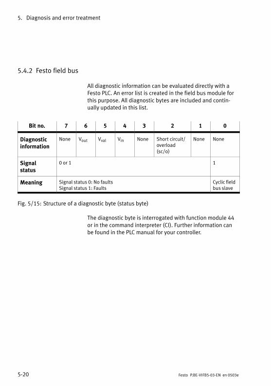
5. Diagnosis and error treatment
5−20 Festo P.BE−VIFB5−03−EN en 0503e
5.4.2 Festo field bus
All diagnostic information can be evaluated directly with aFesto PLC. An error list is created in the field bus module for
this purpose. All diagnostic bytes are included and continually updated in this list.
Bit no. 7 6 5 4 3 2 1 0
Diagnosticinformation
None Vout Vval Vin None Short circuit/overload(sc/o)
None None
Signalstatus
0 or 1 1
Meaning Signal status 0: No faultsSignal status 1: Faults
Cyclic fieldbus slave
Fig.5/15: Structure of a diagnostic byte (status byte)
The diagnostic byte is interrogated with function module 44
or in the command interpreter (CI). Further information canbe found in the PLC manual for your controller.
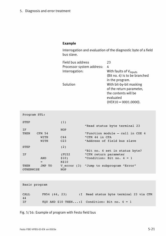
5. Diagnosis and error treatment
5−21Festo P.BE−VIFB5−03−EN en 0503e
Example
Interrogation and evaluation of the diagnostic byte of a fieldbus slave.
Field bus address 23Processor system address: 4
Interrogation: With faults of Vinputs (Bit no. 4) is to be branchedin the program.
Solution With bit−by−bit maskingof the return parameter, the contents will be
evaluated (HEX10 = 0001.0000).
Program STL:
STEP (1)Read status byte terminal 23
IF NOPTHEN CFM 54 Function module call in CZE 4
WITH C44 CFM 44 in CFA WITH C23 Address of field bus slave
STEP (2)Bit no. 4 set in status byte?
IF (FU32 CFM return parameter AND $10) Condition: Bit no. 4 = 1 = K$10
THEN JMP TO V_error (3) Jump to subprogram ErrorOTHERWISE NOP
Basic program
CALL FN54 (44, 23) :I Read status byte terminal 23 via CFM44IF @Q0 AND $10 THEN...:I Condition: Bit no. 4 = 1
Fig.5/16: Example of program with Festo field bus
5. Diagnosis and error treatment
5−22 Festo P.BE−VIFB5−03−EN en 0503e
5.4.3 Diagnosis via ABB CS31
The valve terminal reacts on the ABB CS31 system bus like abinary input/output module. All central units and couplers
perform the general monitoring of the CS31 system bus, e.g.total failure of the local modules.
On the valve terminal, the central units and couplers alsointerrogate the available diagnostic messages (see sectionDiagnostic byte" in this chapter). Depending on their per
formance ability, the diagnostic messages can be processedin detail and can be interrogated with test devices, etc. Thedisplays on the central units and on the couplers indicate the
status of the ABB CS31 system bus and the local modules.
The relevant ABB manuals apply to all the central units and
couplers. The following diagram shows as an example the diagnostic
possibility in conjunction with
central unit 07KR91
coupler 07CS61
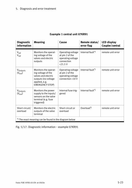
5. Diagnosis and error treatment
5−23Festo P.BE−VIFB5−03−EN en 0503e
Example 1 central unit 07KR91
Diagnosticinformation
Meaning Cause Remote status/error flag
LED displayCoupler/central
VvalVval
Monitors the operating voltage of thevalves and electricoutputs
Operating voltageat pin 2 of the operating voltageconnection<21.5V
Internal fault*) remote unit error
VOutputs(Vout)
Monitors the operating voltage of thevalves and electricoutputs (no voltageapplied, e.g. EMERGENCY STOP)
Operating voltageat pin 2 of the operating voltageconnection <10 V
Internal fault*) remote unit error
VOutputs(Vout)
Monitors the powersupply to the inputs/sensors on the valveterminal (e.g. fusetriggered)
Internal fuse triggered
Internal fault*) remote unit error
Short circuit/overload
Monitors the electricoutputs of the valveterminal
Short circuit oroverload
Overload*) remote unit error
*) The exact meaning can be found in the diagram below
Fig.5/17: Diagnostic information example 07KR91
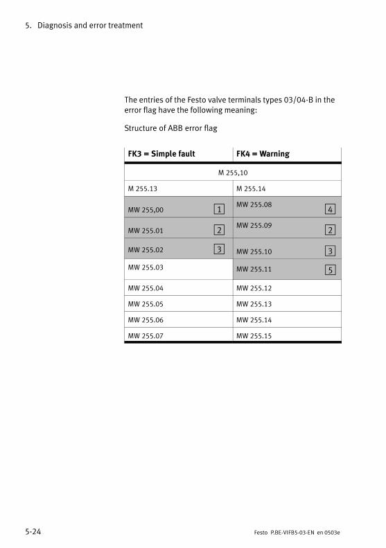
5. Diagnosis and error treatment
5−24 Festo P.BE−VIFB5−03−EN en 0503e
The entries of the Festo valve terminals types 03/04−B in theerror flag have the following meaning:
Structure of ABB error flag
FK3 = Simple fault FK4 = Warning
M255,10
M255.13 M255.14
MW255,00 1 MW255.08 4
MW255.01 2 MW255.09 2
MW255.02 3 MW255.10 3
MW255.03 MW255.11 5
MW255.04 MW255.12
MW255.05 MW255.13
MW255.06 MW255.14
MW255.07 MW255.15
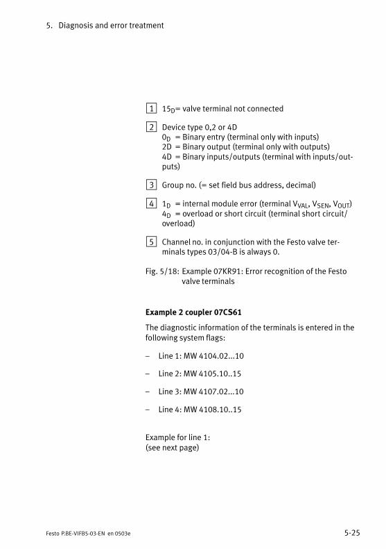
5. Diagnosis and error treatment
5−25Festo P.BE−VIFB5−03−EN en 0503e
1 15D= valve terminal not connected
2 Device type 0,2 or 4D0D = Binary entry (terminal only with inputs)2D = Binary output (terminal only with outputs)4D = Binary inputs/outputs (terminal with inputs/outputs)
3 Group no. (= set field bus address, decimal)
4 1D = internal module error (terminal VVAL, VSEN, VOUT)4D = overload or short circuit (terminal short circuit/overload)
5 Channel no. in conjunction with the Festo valve terminals types 03/04−B is always 0.
Fig.5/18: Example 07KR91: Error recognition of the Festovalve terminals
Example 2 coupler 07CS61
The diagnostic information of the terminals is entered in thefollowing system flags:
Line 1: MW 4104.02...10
Line 2: MW 4105.10..15
Line 3: MW 4107.02...10
Line 4: MW 4108.10..15
Example for line 1:(see next page)
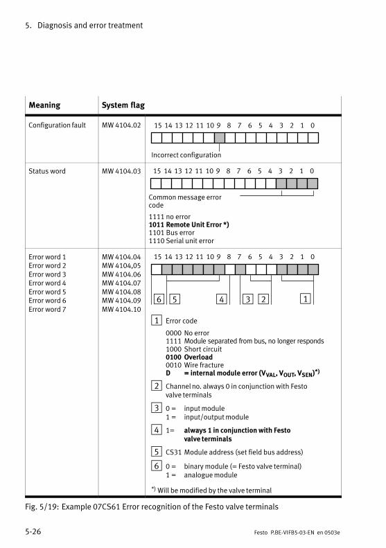
5. Diagnosis and error treatment
5−26 Festo P.BE−VIFB5−03−EN en 0503e
Meaning System flag
Configuration fault MW 4104.02 012345671011121315 14 9 8
Incorrect configuration
Status word MW 4104.03 012345671011121315 14 9 8
Common message errorcode
1111 no error 1011 Remote Unit Error *)1101 Bus error1110 Serial unit error
Error word 1Error word 2Error word 3Error word 4Error word 5Error word 6Error word 7
MW 4104.04MW 4104,05MW 4104.06MW 4104.07MW 4104.08MW 4104.09MW 4104.10
012345671011121315 14 9 8
126 5 4 3
1 Error code
0000 No error 1111 Module separated from bus, no longer responds1000 Short circuit 0100 Overload 0010 Wire fracture D = internal module error (VVAL, VOUT, VSEN)*)
2 Channel no. always 0 in conjunction with Festo valve terminals
3 0 = input module1 = input/output module
4 1= always 1 in conjunction with Festo valve terminals
5 CS31 Module address (set field bus address)
6 0 = binary module (= Festo valve terminal)1 = analogue module
*) Will be modified by the valve terminal
Fig.5/19: Example 07CS61 Error recognition of the Festo valve terminals

5. Diagnosis and error treatment
5−27Festo P.BE−VIFB5−03−EN en 0503e
5.4.4 Diagnosis with Klöckner−Moeller SUCOnet K
The master receives the diagnostic byte from the SUCOnet Kvia the 5th. or 9th. input byte, depending on the equipment
fitted on the valve terminal (up to 28 inputs, more than 28inputs). Further information can be found in the examplebelow and in the PLC manual for your controller.
Example Load diagnostic byte.
Master: PS4−201Field bus address of the valve terminal 2 (= unit no. 1)
Program extract
L RDB1.1.0.8 Status byte of valve terminalno. 1= MB 11
Fig.5/20: Program example Klöckner−Moeller
Structure of diagnostic byte
Bit no. 7 6 5 4 3 2 1 0
Diagnosisinformation
None Vout Vval Vin None Shortcircuit/overload
None None
Signal status L or H
Meaning Signal status L: no errorSignal status H: error
Fig.5/21: Structure of diagnostic byte
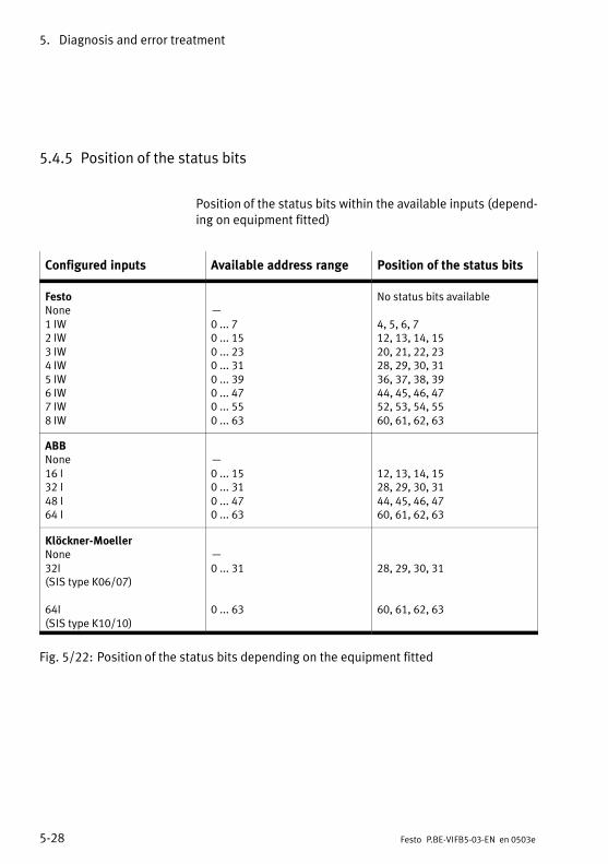
5. Diagnosis and error treatment
5−28 Festo P.BE−VIFB5−03−EN en 0503e
5.4.5 Position of the status bits
Position of the status bits within the available inputs (depending on equipment fitted)
Configured inputs Available address range Position of the status bits
FestoNone1 IW2 IW3 IW4 IW5 IW6 IW7 IW8 IW
0 ... 7 0 ... 150 ... 230 ... 310 ... 390 ... 470 ... 550 ... 63
No status bits available
4, 5, 6, 712, 13, 14, 1520, 21, 22, 2328, 29, 30, 3136, 37, 38, 3944, 45, 46, 4752, 53, 54, 5560, 61, 62, 63
ABBNone16 I 32 I48 I64 I
0 ... 150 ... 310 ... 470 ... 63
12, 13, 14, 1528, 29, 30, 3144, 45, 46, 4760, 61, 62, 63
Klöckner−MoellerNone32I(SIS type K06/07)
64I(SIS type K10/10)
0 ... 31
0 ... 63
28, 29, 30, 31
60, 61, 62, 63
Fig.5/22: Position of the status bits depending on the equipment fitted
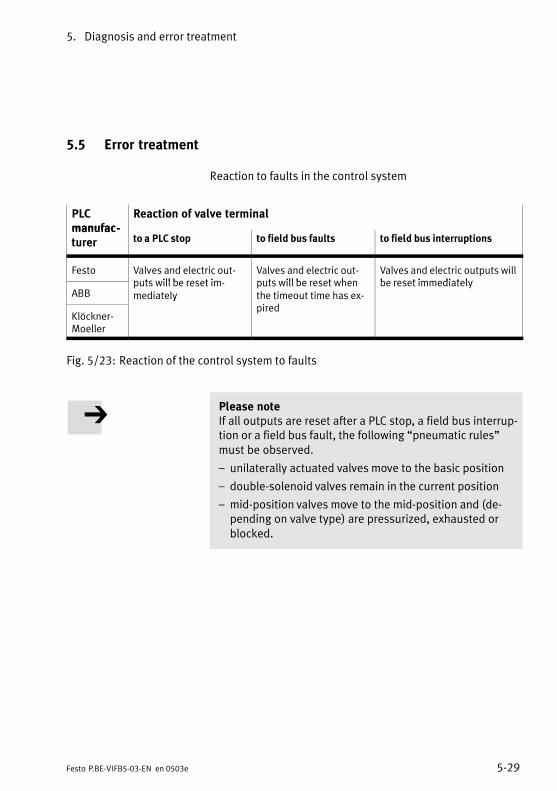
5. Diagnosis and error treatment
5−29Festo P.BE−VIFB5−03−EN en 0503e
5.5 Error treatment
Reaction to faults in the control system
PLCmanufac
Reaction of valve terminalmanufacturer to a PLC stop to field bus faults to field bus interruptions
Festo Valves and electric outputs will be reset im
Valves and electric outputs will be reset when
Valves and electric outputs willbe reset immediately
ABBputs will be reset immediately
puts will be reset whenthe timeout time has exi d
be reset immediately
Klöckner−Moeller
ypired
Fig.5/23: Reaction of the control system to faults
Please noteIf all outputs are reset after a PLC stop, a field bus interruption or a field bus fault, the following pneumatic rules"must be observed.
unilaterally actuated valves move to the basic position
double−solenoid valves remain in the current position
mid−position valves move to the mid−position and (depending on valve type) are pressurized, exhausted orblocked.
5. Diagnosis and error treatment
5−30 Festo P.BE−VIFB5−03−EN en 0503e
5.6 Type 04−B: fuses for the pilot solenoids
The pilot solenoid coils of the valve terminals of type 04−B arefused separately with (quick acting) 0.315 A fuses. Thesefuses are situated on the printed circuit board (behind acover) in each manifold sub−base. Each single−solenoid manifold sub−base is fitted with one fuse; each double−solenoidmanifold sub−base is fitted with two fuses.
Replacing defective/burnt through 0.315 A fuses
In order to replace burnt through fuses, proceed as follows(note also Fig. 5/8).
1. Switch off the compressed air supply and the power supply (connections 1 and 2).
2. Open the cover of the manifold sub−base.
3. Carefully remove the defective/burnt through fuse fromits base (see diagram).
4. Insert a new (quick−acting) 0.315 A fuse.
5. Close the cover.
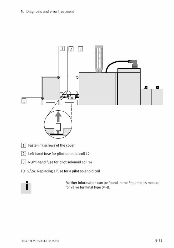
5. Diagnosis and error treatment
5−31Festo P.BE−VIFB5−03−EN en 0503e
1
1 2 3
1 Fastening screws of the cover
2 Left−hand fuse for pilot solenoid coil 12
3 Right−hand fuse for pilot solenoid coil 14
Fig.5/24: Replacing a fuse for a pilot solenoid coil
Further information can be found in the Pneumatics manualfor valve terminal type 04−B.

5. Diagnosis and error treatment
5−32 Festo P.BE−VIFB5−03−EN en 0503e

Technical appendix
A−1Festo P.BE−VIFB5−03−EN en 0503e
Appendix A
A. Technical appendix
A−2 Festo P.BE−VIFB5−03−EN en 0503e
Contents
A.1 Technical specifications A−3. . . . . . . . . . . . . . . . . . . . . . . . . . . . . . . . . . . . . . . . . .
A.2 Cable length and cross−sectional area A−6. . . . . . . . . . . . . . . . . . . . . . . . . . . . . .
A.3 Examples of circuitry A−12. . . . . . . . . . . . . . . . . . . . . . . . . . . . . . . . . . . . . . . . . . . .
A.3.1 Power supply type 03 internal layout A−13. . . . . . . . . . . . . . . . . . . . . . . . . . . . . .
A.3.2 Power supply type 04−B internal layout A−14. . . . . . . . . . . . . . . . . . . . . . . . . . . .
A. Technical appendix
A−3Festo P.BE−VIFB5−03−EN en 0503e
A.1 Technical specifications
General
Protection class (as perEN60529)
Temperature during operation storage/transport
IP 65
− 5°C ... +50°C−20°C +60°C
Vibration(as per DIN/IEC68/EN60068part 2−6 and as perIEC721/EN60068 part 2−3) Transport
Operation/use
Shock(as per DIN/IEC 68/EN60068part 2−27 and IEC 721)
3,5mm path at 2−8Hz1g acceleration at 8−25Hz0,35mm path at 25−57Hz5g acceleration at 57−150 Hz1g acceleration at 150−200Hz
30g at 11ms duration
Protection against electricshock(protection against direct andindirect contact as per IEC/DINEN 60204−1)
by means of PELV circuits(ProtectiveExtra−Low Voltage)
Elektromagnetic compatibility Interference emitted
Immunity against interference
Tested as per DIN EN 61000−6−4(industry)1)
Tested as per DIN EN 61000−6−2(industry)
1) The component is intended for industrial use.
A. Technical appendix
A−4 Festo P.BE−VIFB5−03−EN en 0503e
Operating voltage for electronics and inputs
(pin 1 operating voltage connection) Rated value (protected
against incorrect polarity) Tolerance Residual ripple Current consumption (at 24V)
Fusing the power supply forthe inputs/sensors
Power consumption (P) Calculation
Bridging time (drop inlogicvoltage)
24V DC
± 25% (18V DC ... 30V)4Vpp200mA + sum of internal currentconsumption of inputs2 A, slow−blowing
P[W] = (0.2 A + ∑ Iinputs)⋅ 24V
min. 20ms
Load voltage for outputs/valves
(pin 2 load voltage connection)
Rated value (protectedagainst incorrect polarity)
Tolerance Residual ripple Current consumption (at 24V)
Power consumption (P) Calculation
External fuse required (typ. 10 A,see circuitry examplechapter3.2)24V DC
±10% (DC 21.6V ... 26,4V)4 Vpp10mA+ Sum of current consumption
of outputs+ Sum of current consumption
of switched valve solenoid coils (e.g. per MIDI−valve solenoid coil 55mA)
P[W] = (0.01A+∑Ielectric outputs+∑ISolenoid coil) ⋅ 24V
A. Technical appendix
A−5Festo P.BE−VIFB5−03−EN en 0503e
Field bus
Design RS 485, floating
Transmission type serial asynchronous, half−duplex
Protocol can be set with switch
Festo field bus ABB Procontic CS31 Klöckner−Moeller SUCOnet K
Baud rate can be set with switch
depends on protocol:31.25 kBaud62.5 kBaud187.5 kBaud375 kBaud
Cable length (depends on baudrate and cable type)
max. 4000 m
Cable type (depends on cablelength and field bus baud rateset)
see manual for your controller
Technical specifications for the pneumatics and valves can befound in the Pneumatics catalogue.
Technical specifications for the I/O modules can be found inthe Supplementary description of the I/O modules.
A. Technical appendix
A−6 Festo P.BE−VIFB5−03−EN en 0503e
A.2 Cable length and cross−sectional area
Please noteIt is assumed here that the user is already familiar with theinformation contained in the chapters Installation" in thismanual. The following information is therefore aimed exclusively at personnel trained in electro−technology.
A load−dependent drop in voltage occurs on all three cablesof the power supply to a valve terminal. This can cause thevoltage at pin 1 or pin 2 of the power supply connection to beoutside the permitted tolerance.
Recommendation:
S Avoid long distances between the power unit and thevalve terminal.
S Calculate suitable cable lengths and cross−sectional areaswith the aid of the graphs or formulae below. When doingthis please note the following: the graphs provide approximate values for cross−
sectional areas 1.5 mm2 and 2.5 mm2. the formulae provide exact values for any cross−
sectional area.
Please noteIn the following graphs and formulae it is assumed that thecross−sectional areas of the power supply cables (pins 1, 2and 3) are the same.
A. Technical appendix
A−7Festo P.BE−VIFB5−03−EN en 0503e
Calculating with the graph
Proceed as follows:
1. Calculate the maximum current consumption of the outputs/valves (I2).
2. Calculate the lowest voltage to be expected during operation (VBmin) on thepower unit. When doing this, pleasenote: the load dependency of the power unit the fluctuations in the primary mains voltage
3. Read off the permitted cable length for your cross−sectional area in the relevant table. Example for 1.5 mm2:VBmin = 22.8 V, I2 = 2 A; Lmax = 25 m

A. Technical appendix
A−8 Festo P.BE−VIFB5−03−EN en 0503e
VBmin
Cable length
Current I2 [A]
[V]
[m]
Fig.A/1: Calculating the maximum cable length for cross−sectional area 1.5 mm2
VBmin
Cable length
Current I2 [A]
[m]
[V]
Fig.A/2: Calculating the maximum cable length for cross−sectional area 2.5 mm2

A. Technical appendix
A−9Festo P.BE−VIFB5−03−EN en 0503e
Calculating with a formula
Proceed as follows:
1. Calculate the maximum current consumption of the inputsand electronics (I1) as well as of the outputs/valves (I2).
2. Calculate the lowest voltage to be expected during operation (Vmin) on the power unit. When doing this, pleasenote: the load dependency of the power unit the fluctuations in the primary mains voltage
3. Enter the values in the formula below. The equivalent circuit diagram and the example explain the correlation.
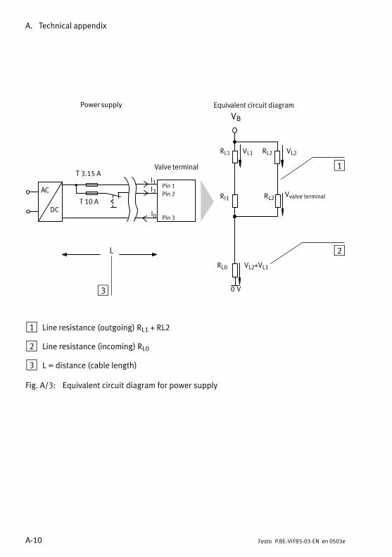
A. Technical appendix
A−10 Festo P.BE−VIFB5−03−EN en 0503e
T 10 A
Pin 1
Pin 2
Pin 3
T 3.15 A
AC
DC
RL1 VL1 RL2 VL2
RI1 RL2
RL0 VL2+VL1
0V
Vvalve terminal
I1I2
I0
Power supply
Valve terminal
Equivalent circuit diagram
L
VB
1
2
3
1 Line resistance (outgoing) RL1 + RL2
2 Line resistance (incoming) RL0
3 L = distance (cable length)
Fig.A/3: Equivalent circuit diagram for power supply
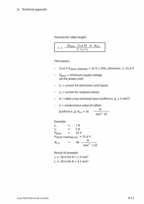
A. Technical appendix
A−11Festo P.BE−VIFB5−03−EN en 0503e
Formula for cable length:
L (VBmin − 21.6V) · A · κCU
2 I2 + I1
This means:
21.6 V VVALVE TERMINAL = 24 V ± 10%, minimum: 21.6 V
VBmin = minimum supply voltage (at the power unit)
l1 = current for electronics and inputs
I2 = current for outputs/valves
A = cable cross−sectional area (uniform e.g. 1.5 mm2)
κ = conductance value of cables
(uniform e.g. κCu = 56m
mm2 · Ω
Example: I1 = 1 AI2 = 5 AVBmin = 24 VVVALVE TERMINALmin = 21.6 V
κCu = 56m
mm2 · ≅ Ω
Result of example:
L 18 m for A = 1.5 mm2
L 30 m for A = 2.5 mm2
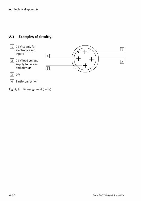
A. Technical appendix
A−12 Festo P.BE−VIFB5−03−EN en 0503e
A.3 Examples of circuitry
1 24V supply forelectronics andinputs
2 24V load voltagesupply for valvesand outputs
3 0V
4 Earth connection
1
2
3
4
Fig.A/4: Pin assignment (node)
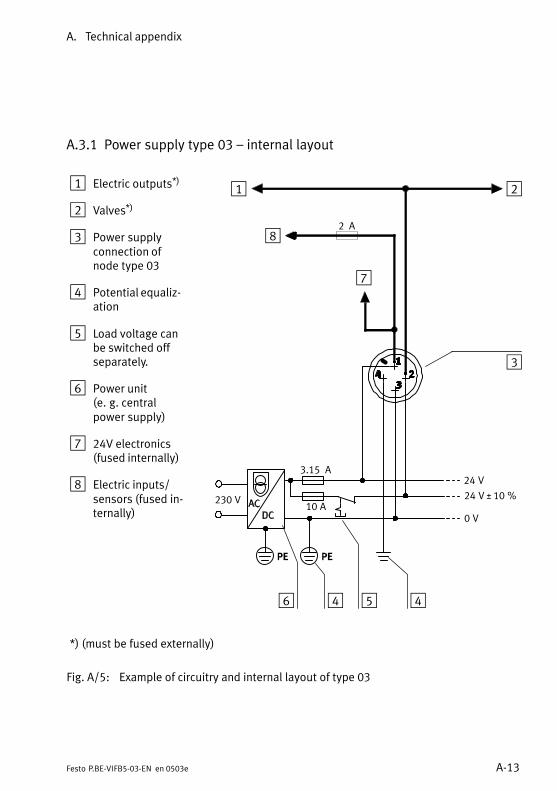
A. Technical appendix
A−13Festo P.BE−VIFB5−03−EN en 0503e
A.3.1 Power supply type 03 internal layout
1 Electric outputs*)
2 Valves*)
3 Power supplyconnection ofnode type03
4 Potential equalization
5 Load voltage canbe switched offseparately.
6 Power unit(e.g.centralpower supply)
7 24V electronics(fused internally)
8 Electric inputs/sensors (fusedinternally)
1 2
8
7
230V
3.15 A
10A
2 A
24V
24V ± 10%
0V
456
3
4
*) (must be fused externally)
Fig.A/5: Example of circuitry and internal layout of type 03
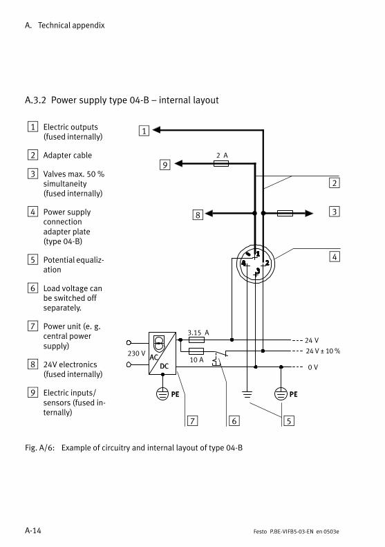
A. Technical appendix
A−14 Festo P.BE−VIFB5−03−EN en 0503e
A.3.2 Power supply type 04−B internal layout
1 Electric outputs(fused internally)
2 Adapter cable
3 Valves max. 50 %simultaneity(fused internally)
4 Power supplyconnectionadapter plate(type 04−B)
5 Potential equalization
6 Load voltage canbe switched offseparately.
7 Power unit (e.g.central powersupply)
8 24V electronics(fused internally)
9 Electric inputs/sensors (fused internally)
1
2
7
230V
3.15 A
10A
2 A
24V
24V ± 10%
0V
3
56
8
4
9
Fig.A/6: Example of circuitry and internal layout of type 04−B
Accessories
B−1Festo P.BE−VIFB5−03−EN en 0503e
Appendix B
B. Accessories
B−2 Festo P.BE−VIFB5−03−EN en 0503e
Contents
B.1 Connecting the cables to the plugs/sockets B−3. . . . . . . . . . . . . . . . . . . . . . . . .
B. Accessories
B−3Festo P.BE−VIFB5−03−EN en 0503e
B.1 Connecting the cables to the plugs/sockets
CautionThe position of the pins on the plug is different from thaton the socket.
The connections of the input/output modules are in theform of sockets.
The connections for the power supply are in the form ofplugs.
Please see the following chapters for the pin assignment.
When you have selected suitable cables, connect them to theplugs/sockets in accordance with the steps listed below.
1. Open the Festo plugs/sockets as follows (see diagram):
Mains power supply socket Insert the power supply socket in the power supplyconnection of the valve terminal. Unscrew the housing of the socket.Then remove the connecting part of the socket whichinserted in the power supply connection.
Sensor plug (for input/output modules):Loosen the centre knurled nut.
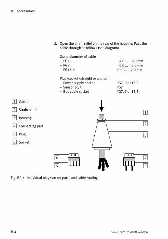
B. Accessories
B−4 Festo P.BE−VIFB5−03−EN en 0503e
2. Open the strain relief on the rear of the housing. Pass thecable through as follows (see diagram).
Outer diameter of cable PG7: 4.0 ... 6.0 mm PG9: 6.0 ... 8.0 mm PG13.5: 10.0 ... 12.0 mm
Plug/socket (straight or angled): Power supply socket PG7, 9 or 13.5 Sensor plug PG7 Bus cable socket PG7, 9 or 13.5
1 Cables
2 Strain relief
3 Housing
4 Connecting part
5 Plug
6 Socket
1
2
3
4
56
4 ÎÎÎÎÎÎ
ÎÎÎÎÎÎ
Fig.B/1: Individual plug/socket parts and cable routing
B. Accessories
B−5Festo P.BE−VIFB5−03−EN en 0503e
3. Remove 5 mm of insulation from the end of the conductors.
4. Fit end sleeves to the wires.
5. Connect the conductors.
6. Place the connecting part back on the housing of the plugand screw the two items together. Pull the cable back sothat there are no loops inside the housing.
7. Tighten the strain relief.

B. Accessories
B−6 Festo P.BE−VIFB5−03−EN en 0503e

Index
C−1Festo P.BE−VIFB5−03−EN en 0503e
Appendix C
C. Index
C−2 Festo P.BE−VIFB5−03−EN en 0503e
Contents
C. Index C−1. . . . . . . . . . . . . . . . . . . . . . . . . . . . . . . . . . . . . . . . . . . . . . . . . . . . . . . . .
C. Index
C−3Festo P.BE−VIFB5−03−EN en 0503e
A
ABBAddressing 4−22, 4−24. . . . . . . . . . . . . . . . . . . . . . . . . . . . . . Setting the field bus protocol 3−14. . . . . . . . . . . . . . . . . . . . Settings of the valve terminal 3−10, 3−13. . . . . . . . . . . . . . .
Abbreviations VIII. . . . . . . . . . . . . . . . . . . . . . . . . . . . . . . . . . . .
AddressFesto 4−17. . . . . . . . . . . . . . . . . . . . . . . . . . . . . . . . . . . . . . . . Field bus/valve terminal 3−10. . . . . . . . . . . . . . . . . . . . . . . . Klöckner−Moeller 4−30. . . . . . . . . . . . . . . . . . . . . . . . . . . . . .
Address assignmentGeneral 4−6. . . . . . . . . . . . . . . . . . . . . . . . . . . . . . . . . . . . . . .
C
CablesConnecting B−3. . . . . . . . . . . . . . . . . . . . . . . . . . . . . . . . . . . . Field bus 3−4. . . . . . . . . . . . . . . . . . . . . . . . . . . . . . . . . . . . . . Load voltage 3−15, A−6. . . . . . . . . . . . . . . . . . . . . . . . . . . . . . Selection 3−4, 3−6, A−6. . . . . . . . . . . . . . . . . . . . . . . . . . . . . .
ConnectingPower supply 3−15. . . . . . . . . . . . . . . . . . . . . . . . . . . . . . . . .
ConnectionsElectric modules 1−4. . . . . . . . . . . . . . . . . . . . . . . . . . . . . . . . ISO modules 1−7. . . . . . . . . . . . . . . . . . . . . . . . . . . . . . . . . . . MAXI modules 1−6. . . . . . . . . . . . . . . . . . . . . . . . . . . . . . . . . MIDI modules 1−5. . . . . . . . . . . . . . . . . . . . . . . . . . . . . . . . . .
CurrentCalculation 3−16. . . . . . . . . . . . . . . . . . . . . . . . . . . . . . . . . . . Fuse 3−18. . . . . . . . . . . . . . . . . . . . . . . . . . . . . . . . . . . . . . . . . Selecting the cables 3−6, A−6. . . . . . . . . . . . . . . . . . . . . . . . .
D
Data transmission Baud rate 3−12. . . . . . . . . . . . . . . . . . . . . . . . . . . . . . . . . . . .
DiagnosisBus node 5−4. . . . . . . . . . . . . . . . . . . . . . . . . . . . . . . . . . . . . .
C. Index
C−4 Festo P.BE−VIFB5−03−EN en 0503e
LEDs 5−4. . . . . . . . . . . . . . . . . . . . . . . . . . . . . . . . . . . . . . . . . Status bits 5−27. . . . . . . . . . . . . . . . . . . . . . . . . . . . . . . . . . . .
E
EarthingComponents 2−4. . . . . . . . . . . . . . . . . . . . . . . . . . . . . . . . . . . Potential equalization 3−20. . . . . . . . . . . . . . . . . . . . . . . . . .
EMERGENCY STOP circuit 3−18. . . . . . . . . . . . . . . . . . . . . . . . .
End plates 2−4, 2−5. . . . . . . . . . . . . . . . . . . . . . . . . . . . . . . . . . .
F
FaultsDiagnostic byte 5−18. . . . . . . . . . . . . . . . . . . . . . . . . . . . . . . . Status bits 5−27. . . . . . . . . . . . . . . . . . . . . . . . . . . . . . . . . . . . Treatment 5−3. . . . . . . . . . . . . . . . . . . . . . . . . . . . . . . . . . . . .
FaultsField bus 3−4, 3−23, 5−28. . . . . . . . . . . . . . . . . . . . . . . . . . . . PLC 5−28. . . . . . . . . . . . . . . . . . . . . . . . . . . . . . . . . . . . . . . . . .
FestoAddressing 4−17. . . . . . . . . . . . . . . . . . . . . . . . . . . . . . . . . . . Configuration 4−15. . . . . . . . . . . . . . . . . . . . . . . . . . . . . . . . . Programming examples 4−19. . . . . . . . . . . . . . . . . . . . . . . . . Settings of the valve terminal 3−10. . . . . . . . . . . . . . . . . . . .
Festo field busLocating faults 5−19. . . . . . . . . . . . . . . . . . . . . . . . . . . . . . . . Programming examples 5−20. . . . . . . . . . . . . . . . . . . . . . . . .
Field busAddress 3−10. . . . . . . . . . . . . . . . . . . . . . . . . . . . . . . . . . . . . . Baud rate 3−12. . . . . . . . . . . . . . . . . . . . . . . . . . . . . . . . . . . . Protocol 3−12. . . . . . . . . . . . . . . . . . . . . . . . . . . . . . . . . . . . . . Terminating resistor 3−28. . . . . . . . . . . . . . . . . . . . . . . . . . . .
Field bus protocol Setting 3−14. . . . . . . . . . . . . . . . . . . . . . . . . . . . . . . . . . . . . . .
FuseExternal 3−18, 3−21. . . . . . . . . . . . . . . . . . . . . . . . . . . . . . . . . Internal 3−21. . . . . . . . . . . . . . . . . . . . . . . . . . . . . . . . . . . . . .
C. Index
C−5Festo P.BE−VIFB5−03−EN en 0503e
H
Hat rail 2−6. . . . . . . . . . . . . . . . . . . . . . . . . . . . . . . . . . . . . . . . .
I
Inputs Calculating 4−5. . . . . . . . . . . . . . . . . . . . . . . . . . . . . . . . . . . .
Intended use V. . . . . . . . . . . . . . . . . . . . . . . . . . . . . . . . . . . . . .
INTERBUSAddressing 4−13. . . . . . . . . . . . . . . . . . . . . . . . . . . . . . . . . . . Configuration 4−13. . . . . . . . . . . . . . . . . . . . . . . . . . . . . . . . .
K
Klöckner−MoellerDiagnosis 5−26. . . . . . . . . . . . . . . . . . . . . . . . . . . . . . . . . . . . Programming example 4−32. . . . . . . . . . . . . . . . . . . . . . . . . .
L
LED displayInputs 5−10. . . . . . . . . . . . . . . . . . . . . . . . . . . . . . . . . . . . . . . Node 3−8, 5−4, 5−5. . . . . . . . . . . . . . . . . . . . . . . . . . . . . . . . . . Outputs 5−10. . . . . . . . . . . . . . . . . . . . . . . . . . . . . . . . . . . . . .
O
Outputs Calculating 4−5. . . . . . . . . . . . . . . . . . . . . . . . . . . . . . . . . . . .
P
Pictograms VII. . . . . . . . . . . . . . . . . . . . . . . . . . . . . . . . . . . . . .
Pin assignment Operating voltage 3−19. . . . . . . . . . . . . . . . . . . . . . . . . . . . . .
Power supplyCable length A−6. . . . . . . . . . . . . . . . . . . . . . . . . . . . . . . . . . .
C. Index
C−6 Festo P.BE−VIFB5−03−EN en 0503e
Switching on 4−14. . . . . . . . . . . . . . . . . . . . . . . . . . . . . . . . . .
power supply connection 3−18. . . . . . . . . . . . . . . . . . . . . . . . .
Power unit 3−15. . . . . . . . . . . . . . . . . . . . . . . . . . . . . . . . . . . . .
Programming examplesFesto field bus 4−19, 5−20. . . . . . . . . . . . . . . . . . . . . . . . . . . Klöckner−Moeller 4−32. . . . . . . . . . . . . . . . . . . . . . . . . . . . . .
S
Service V. . . . . . . . . . . . . . . . . . . . . . . . . . . . . . . . . . . . . . . . . . .
Siemens Locating faults 5−3. . . . . . . . . . . . . . . . . . . . . . . . . . . . . . . . .
Status bits 5−14. . . . . . . . . . . . . . . . . . . . . . . . . . . . . . . . . . . . .
Switching statusInputs 5−9. . . . . . . . . . . . . . . . . . . . . . . . . . . . . . . . . . . . . . . . Outputs 5−9. . . . . . . . . . . . . . . . . . . . . . . . . . . . . . . . . . . . . . .
T
Target group V. . . . . . . . . . . . . . . . . . . . . . . . . . . . . . . . . . . . . . .
Technical specifications A−3. . . . . . . . . . . . . . . . . . . . . . . . . . . .
Terminating resistor 3−28. . . . . . . . . . . . . . . . . . . . . . . . . . . . . .
Text markings VII. . . . . . . . . . . . . . . . . . . . . . . . . . . . . . . . . . . .
the data transmission Protocol 3−12. . . . . . . . . . . . . . . . . . . . . . . . . . . . . . . . . . . . . .
Transmission times 4−28. . . . . . . . . . . . . . . . . . . . . . . . . . . . . .
U
User instructions VI. . . . . . . . . . . . . . . . . . . . . . . . . . . . . . . . . .
V
ValvesISO 1−7. . . . . . . . . . . . . . . . . . . . . . . . . . . . . . . . . . . . . . . . . . .
C. Index
C−7Festo P.BE−VIFB5−03−EN en 0503e
MAXI 1−3, 1−6. . . . . . . . . . . . . . . . . . . . . . . . . . . . . . . . . . . . . MIDI 1−3, 1−5. . . . . . . . . . . . . . . . . . . . . . . . . . . . . . . . . . . . . .
Voltage Selecting the cables 3−6, 3−15. . . . . . . . . . . . . . . . . . . . . . . .

C. Index
C−8 Festo P.BE−VIFB5−03−EN en 0503e