Embed Size (px)
Citation preview

Valve terminals CPV, Compact Performance

Subject to change – 2019/052 � Internet: www.festo.com/catalog/...
Valve terminals CPV, Compact PerformanceKey features
Innovative Versatile Reliable Easy to mount
� Cubic design for exceptional
performance and low weight
� Low installation and bus
connection costs
� Ideal for decentralised machines
and system structures, for example
– in handling technology
– in conveyor technology
– in the packaging industry
– in sorting systems
– in upstream machine functions
� Integrated diagnostics, condition
monitoring (Fieldbus Direct)
� A string extension for Fieldbus
Direct of 8 … 32 inputs and 8 … 32
outputs is possible without any
difficulty (version-dependent)
� Flexible and cost-effective
connection of 2 to 8 valve slices
� Highly flexible thanks to:
– various pneumatic functions
(valve variants)
– different pressure ranges
– vacuum switches
– integrated vacuum generation
– relay plates with floating
electrical outputs
� Separator plates for creating
pressure zones
� Valves with integrated separation of
ducts 1 and 11
� Blanking plates for future
expansion
� LED displays
� Manual overrides for valves
� Protection class to IP65
� Protection class IP65 also in con
junction with pneumatic multiple
connector plate for control cabinet
assembly
� CE mark
� ATEX certification
(see Technical Data)
� Ready-to-install and tested unit
� Lower selection, ordering, installa
tion and commissioning costs
� Secure mounting on wall or H-rail
� Pneumatic multiple connector plate
– fast assembly without the need to
replace the connected tubing
� Optimised assembly for control
cabinets

2019/05 – Subject to change 3� Internet: www.festo.com/catalog/...
Valve terminals CPV, Compact PerformanceKey features
CPV – The benefits at a glance
The CPV valve terminal has a unique
design. It provides the flexible com
bination of pneumatic performance,
electrical connection technologies and
a wide range of mounting options. The
pneumatic multiple connector plate
supports space-saving installation in
control cabinets. In many cases the
valve terminal can be installed in the
previously unused wall area of the
control cabinet. There is no need to
connect the valves in the control
cabinet. All tube couplings can be laid
externally. Instead of individual holes,
the pneumatic multiple connector
plate requires only one rectangular
cutout.
The generously sized flow ducts and
powerful flat plate silencers ensure
high flow rates.
All valves are in the form of valve
slices. They are optimised for flow
performance and are also extremely
compact. Two functions per valve slice
(e.g. 2x 3/2-way valves) mean that
twice the component density can be
achieved. This saves space and
reduces costs.
The cubic design permits exceptional
performance yet a comparatively low
weight. The benefits of this design are
obvious when the valve terminal is
used on a drive in a moving
installation.
However, robustness must not be
sacrificed in favour of compactness.
The connecting threads and mounting
attachments are metal.
The manual override for the valves can
be adapted for different operating
situations. If, for example, a detenting
manual override is required for
setting-up mode, the manual override
can be easily converted for that
application in a way that rules out
operational errors.
The clear, large labelling system also
contributes to the safe operation of
the valve terminal.
A particular plus is the range of elec
trical connection technologies sup
ported. All types of valve actuation are
possible, from individual valve con
nections up to bus systems with versa
tile expansion options. The integration
of electrical input and output modules
permits cost-effective solutions within
the different installation concepts.
The design principle
The cubic design provides a clearly
assigned function on each side. Thus,
for example, the electrical connection
is mounted on the top.
An optional inscription label holder
can be placed on the front of the valve
terminal.
The different combination options en
sure the optimum solution for the task
at hand.
� Compressed air supply connections
on the left, right or underneath
� Pneumatic working lines and
function blocks (vertical stacking)
underneath
� Manual operation/identification
on the front
� Electrical connection surface
on the top
� Mounting surface at the back or
the front via a pneumatic multiple
connector plate

Subject to change – 2019/054 � Internet: www.festo.com/catalog/...
Valve terminals CPV, Compact PerformanceKey features
Main features
Inscription labels
Reduced downtimes:
On-the-spot diagnostics via LEDs
Robust metal thread or
pre-assembled QS connectors
Comprehensive range of valve functions,
pressure zone creation, blanking plates
Simple electrical connections:
– Individual connection/ET200X/ET200pro
– Multi-pin plug
– AS-interface
– I-Port interface/IO-Link
– Installation system CP/CPI
– Fieldbus Direct
Operating voltage connection
Quick mounting:
– Directly using screws
– On an H-rail
– Via the pneumatic multiple connector
plate
Reliable operation:
Manual override, non-detenting, detenting
or blocked
Width
– 10 mm
– 14 mm
– 18 mm
Equipment options
Valve functions
� 5/2-way valve, single solenoid
� 5/2-way valve (with duct separation
1, 11), single solenoid
� 5/2-way valve, single solenoid,
fast-switching
� 5/2-way valve, double solenoid
� 5/2-way valve (with duct separation
1, 11), double-solenoid
� 2x 3/2-way valve, normally closed
� 2x 3/2-way valve (with duct
separation 1, 11), normally closed
� 2x 3/2-way valve, normally open
� 2x 3/2-way valve (with duct
separation 1, 11), normally open
� 2x 3/2-way valve, 1x normally
open, 1x closed
� 2x 3/2-way valve, (with duct
separation 1, 11) 1x normally
open, 1x closed
� 2x 3/2-way valve, normally closed,
integrated back pressure protection
� 5/3-way valve, mid-position closed
� 2x 2/2-way valve, normally closed
� 2x 2/2-way valve (with duct
separation 1, 11), normally closed
� 2x 2/2-way valve, 1x normally
open, 1x closed
� 2x 2/2-way valve, (with duct
separation 1, 11) 1x normally
open, 1x closed
� Vacuum generator
� Vacuum generator and 2/2-way
valve with ejector pulse
� On some terminals a relay plate
with two floating contacts can be
chosen instead of a valve sub-base
Special features
Individual connection Electrical connection for ET200X/ET200pro Multi-pin plug connection
� 2 … 8 valve positions,
max. 16 solenoid coils
� 8 valve positions,
max. 16 solenoid coils
� 4, 6 or 8 valve positions,
max. 16 solenoid coils
-H- Note
A moulded seal is required for the
valve terminal CPV10-ET200pro in
order to achieve the IP protection
class.
The moulded seal CPV10-…-GE-8
or CPV14-…-GE-8 must be ordered
separately.
AS-interface I-Port interface/IO-Link Installation system CP/CPI Fieldbus Direct
� 2, 4 or 8 valve positions,
max. 8 solenoid coils
� 4 or 8 inputs for 4 or 8 valve
positions
� 8 valve positions,
max. 16 solenoid coils
� Direct connection to the CTEU/CTEL
installation system from Festo
(I-Port)
� Connection to an IO-Link master
� 4, 6 or 8 valve positions,
max. 16 solenoid coils
� CP/CPI string extension enables
further valve terminals and I/O
modules with CP/CPI function to be
connected
� 8 valve positions,
max. 16 solenoid coils
� CP/CPI string extension enables
further valve terminals and I/O
modules with CP/CPI functions to
be connected

2019/05 – Subject to change 5� Internet: www.festo.com/catalog/...
Valve terminals CPV, Compact PerformanceKey features
Electrical connections
Individual connection (valve manifold)
Connection is independent of the
control technology used and is flexible
thanks to pre-assembled cables. This
ensures correct polarity during
installation. The connector plug is
equipped with an LED that indicates
switching status, and an overvoltage
protective circuit. It also features a
built-in current reduction circuit.
Individual connection permits the
selection of 2 to 16 solenoid coils
(divided between 2 to 8 valve slices,
odd numbers also possible).
An intrinsically safe version rounds off
the range.
Additional information
� Internet: cpv10-ex-vi
ET200X/ET200pro pneumatic interface for CPV10 and CPV14
Adaptation of the CPV valve manifold
to the input/output module
ET200X/ET200pro from Siemens:
the combination of the functional
module of the ET200X/ET200pro and
the pneumatic functions of the CPV
valve manifold provides a highly
integratable automation solution
for systems using electrical and
pneumatic drives with:
� 8 valve slices for up to 16 CPV
valves
� Fast and secure contacting to IP65
� CPV10 and CPV14 valve manifold
� Not permitted for CPV10-EX-VI
� High IP65/IP67 protection
� Modular design
Multi-pin plug connection
Control signals from the controller to
the valve terminal are transmitted via
a pre-assembled multi-wire cable,
which substantially reduces
installation time. The current
reduction circuit for the valves is also
integrated in the multi-pin plug
connection.
This valve terminal can be equipped
with 4 to 16 solenoid coils (4, 6 or
8 valve slices).
AS-interface connection
A special feature of the AS-interface is
the simultaneous transmission of
data and supply power via a two-wire
cable. The encoded cable profile
prevents connection with incorrect
polarity. If the valves have to be
disconnected from mains power in an
emergency, they can also be supplied
with electrical power via a separate
connection. Two versions are
available for valve terminals for A/B
operation.
The valve terminal with AS-interface is
available in the following versions:
� Without inputs, with two or four
valve slices (max. 4 solenoid coils)
and additional power supply
� With four inputs and four valve
slices (max. 8 solenoid coils)
� With four or eight inputs and four or
eight valve slices (max. 8 solenoid
coils) and additional power supply
� With four or eight inputs and four or
eight valve modules incl. vacant po
sition or vacant positions and addi
tional power supply (max. 6 solen
oid coils for A/B mode in accord
ance with SPEC.2.1, max. 8 solen
oid coils for A/B mode in accord
ance with SPEC. 3.0 with Profile
7.A.7)
Additional information
� Internet: as-interface
-H- Note
Valve terminals to SPEC.2.1 cannot
be operated on a master to
SPEC.3.0 with profile 7.A.7.

Subject to change – 2019/056 � Internet: www.festo.com/catalog/...
Valve terminal CPV, Compact PerformanceSelection and development
Electrical connections
I-Port interface/IO-Link, CTEL installation system
A CTEL system consists of the CTEL
master and the devices with I-Port
interface, which are connected
together using special connecting
cables. This permits a decentralised
layout of the devices. This means
that the valve terminals and
I/O modules with I-Port interface
(devices) can be mounted very close
to the cylinders to be controlled.
This reduces the length of the air
supply lines used, which minimises
flow losses and pressurisation and
venting times.
The I-Port interface from Festo is
based on IO-Link and is compatible
with IO-Link in certain areas.
The connection type corresponds to
a star topology. In other words, only
one module or valve terminal can be
connected to each I-Port.
As well as communication, the
I-Port interfaces also handle the
power supply for the connected
devices.
The maximum length of a string is
20 m.
The restrictions compared to IO-Link
include:
� Permanently set baud rate of
230.4 kbps
� SIO mode is not supported
� Max. 32 bytes of input data and
32 bytes of output data
� Only one dump of the master
commands is used
� "Festo plug & work" principle,
configuration via IODD is not sup
ported.
More information
� Internet: cteu
� Internet: cpx
� Internet: cecc
I-Port interface/IO-Link, CTEU system
CTEU is a system for compact
connection of a valve terminal to
different fieldbus standards such as
Profibus and DeviceNet.
The fieldbus node is mounted
directly on the I-Port interface of the
valve terminal.
This makes it easier to switch
between the fieldbus protocols than
with Fieldbus Direct, however there
is no way of connecting I/O modules
to the fieldbus nodes (as with the
CPI string extension).
The following fieldbus protocols are
supported:
� DeviceNet
� Profibus DP
� CANopen
� CC-Link
� EtherCAT
More information
� Internet: cteu
2019/05 – Subject to change 7� Internet: www.festo.com/catalog/...
Valve terminals CPV, Compact PerformanceKey features
Electrical connections
Installation system CP/CPI
Valve terminals with CP connection
are intended for connection to higher-
order bus nodes or to control blocks.
A bus node or control block also en
ables the connection of decentralised
input/output units. The following bus
protocols are supported:
� PROFIBUS DP
� INTERBUS
� DeviceNet
� CANopen
� CC-Link
� EtherNet/IP
� PROFINET
� POWERLINK
� EtherCAT
� Sercos III
Four strings with up to 32 inputs and
32 outputs (version-dependent) can
be connected to a bus node or control
block. The CPV valve terminal is
treated like an output module with up
to 8 outputs (4, 6 or 8 valve slices or
4 to 16 solenoid coils per terminal).
The connecting cables transmit all re
quired electrical signals (control sig
nals, operating voltage for the internal
electronics of the modules and load
voltage supply for connected valves).
Additional information
� Internet: ctec
Fieldbus Direct
Fieldbus Fieldbus Direct is a system for the
compact connection of a CPV or
CPV-SC valve terminal to different
fieldbus standards such as PROFIBUS
and DeviceNet.
The fieldbus node is directly inte
grated in the electrical interface of the
valve terminal and therefore takes up
only a minimal amount of space.
The CPI string extension option allows
the functions and components of the
CPI system to be used.
The new high-performance CPI string
extension offers up to 4 supplemen
tary CPI modules, combined with CP
or CPI-compatible valve terminals for
extension purposes. The Fieldbus Di
rect system can be expanded by 8 …
32 inputs and 8 … 32 outputs without
any difficulty.

Subject to change – 2019/058 � Internet: www.festo.com/catalog/...
Valve terminals CPV, Compact PerformanceSelection and development
Valve terminal configurator Online via: � www.festo.com
The appropriate valve terminal can be
chosen quickly and easily using the
online catalogue. This includes an
easy-to-use valve terminal configura
tor, which makes it much easier to
find the right product.
The valve terminals are fully as
sembled according to your order spec
ification and are individually tested.
This reduces assembly and
installation time to a minimum.
You order a valve terminal CPV using
the order code.
Ordering system for CPV
� Internet: cpv
2D/3D CAD data Online via: � www.festo.com
You can request the CAD data for a
valve terminal you have configured. To
do so, perform the product search as
described above. Go to the shopping
basket and click on the CAD icon
(compass). On the next page you can
generate a 3D preview or request
another data format of your choice by
e-mail.
2019/05 – Subject to change 9� Internet: www.festo.com/catalog/...
Valve terminals CPV, Compact PerformancePeripherals overview
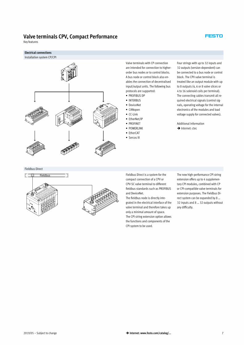
Overview – CPV valve terminal
9
2
5
4
6
78
3
1
aJ
aA
aB
aC
1 Basic electrical unit (Fieldbus
Direct, CP/CPI installation
system, I-Port interface/IO-Link,
AS-interface, multi-pin plug,
individual connection)
2 Right-hand end plate with flat
plate silencer
3 Comprehensive range of valve
functions
4 Right-hand end plate (threaded
connections not in conjunction
with pneumatic multiple
connector plate)
5 Holder for inscription label
6 QS push-in connectors
7 Function block (vertical stacking)
8 Pneumatic multiple connector
plate
9 Left-hand end plate (threaded
connections not in conjunction
with pneumatic multiple
connector plate)
aJ Left-hand end plate with flat
plate silencer
aA H-rail mounting
aB Wall mounting
aC Connecting cable for individual
connection

Subject to change – 2019/0510 � Internet: www.festo.com/catalog/...
Valve terminals CPV, Compact PerformanceKey features – Pneumatic components
Valves
CPV valves are valves with integrated
sub-base, i.e. in addition to the valve
function they contain all of the pneu
matic ducts for supply, exhaust and
the working lines. The supply ducts
are a central component of the valve
slices and allow a direct flow of air
through the valve slices.
This helps achieve maximum flow
rates. All valves have a pneumatic
pilot control for optimising perform
ance. The valve function is based on
a piston spool system with a patented
sealing principle that guarantees its
suitability for a wide range of applica
tions as well as a long service life.
The pneumatic components and
functions are always identical for all
actuator types. Most functions are
also available in the various valve
sizes (grid dimensions). Restrictions
are noted where applicable.
Valve function
Code Circuit symbol Size Description
10 14 18
M, MK
� � �
5/2-way valve, single solenoid
� Pneumatic spring return
� Piston spool valve
� With duct separation 1, 11 for valve MK
� Size 18 only available for valve M
F
� – –
5/2-way valve, single solenoid
� Pneumatic spring return
� Piston spool valve
� Fast switching
J, JK
� � �
5/2-way valve, double solenoid
� Piston spool valve
� With duct separation 1, 11 for valve JK
� Size 18 only available for valve J
C, CK
� � �
2x 3/2-way valve, single solenoid
� Normally closed
� Pneumatic spring return
� Piston spool valve
� With duct separation 1, 11 for valve CK
� Size 18 only available for valve C
CY
� – –
2x 3/2-way valve, single solenoid
� Normally closed
� Pneumatic spring return
� Integrated back pressure protection
� Piston spool valve
� Not suitable for vacuum
-H- Note
The valve terminal must be operated with external pilot air supply if it is
necessary to ensure that the back pressure flaps are closed securely in the
event of a sudden drop in operating pressure or if the operating pressure is
switched off.

2019/05 – Subject to change 11� Internet: www.festo.com/catalog/...
Valve terminals CPV, Compact PerformanceKey features – Pneumatic components
Valve function
Code Circuit symbol Size Description
10 14 18
N, NK
� � �
2x 3/2-way valve, single solenoid
� Normally open
� Pneumatic spring return
� Piston spool valve
� With duct separation 1, 11 for valve NK
� Size 18 only available for valve N
The function of a 5/3-way valve with mid-position pressurised
can be implemented with these valves with initial position open.
H, HK
� � �
2x 3/2-way valve, single solenoid
� Normal position
– 1x open (pilot control 12)
– 1x closed (pilot control 14)
� Pneumatic spring return
� Piston spool valve
� With duct separation 1, 11 for valve HK
� Size 18 only available for valve H
For optimised cylinder movement. Corresponds to valve function M with simul
taneous actuation of both solenoid coils (5/2-way, single solenoid). Since the
piston area on each side can be pressurised or exhausted separately, it means
that the cylinder can move faster.
G
– – �
5/3-way valve, mid-position closed
� Mechanical spring return
� Piston spool valve
� � –
5/3G1) function, mid-position closed
For size 10 and 14
The valve function “mid-position closed” is created from one 2x 3/2-way valve,
normally closed (code C).
The valve kit CPV10-BS-5/3G-M7 or CPV14-BS-5/3G-1/8 (incorporating
a double piloted non-return valve function) is used for this. This valve kit is
intended for applications with one working pressure level per valve slice, i.e. it
must not be used in dual-pressure applications (where the pressure levels at
port 1 and 11 are different).
If other valve slices are to be used in dual-pressure mode, then the valve slice
equipped with the 5/3G valve kit must be separated from compressed air
duct 1 and 11 by means of a separator plate (code T).
Not in first or last valve position with pneumatic multiple connector plate P
and M. Cannot be used with pneumatic multiple connector plate GQC and
GQD.
� Piston spool valve
1) Cannot be assembled in conjunction with the control cabinet version of the pneumatic multiple connector plate CPV10-VI-P...-C or CPV10-VI-P...-D
-H- Note
A filter must be installed upstream of valves operated in vacuum mode.
This prevents any foreign matter in the intake air getting into the valve
(e.g. when operating a suction cup).
Subject to change – 2019/0512 � Internet: www.festo.com/catalog/...
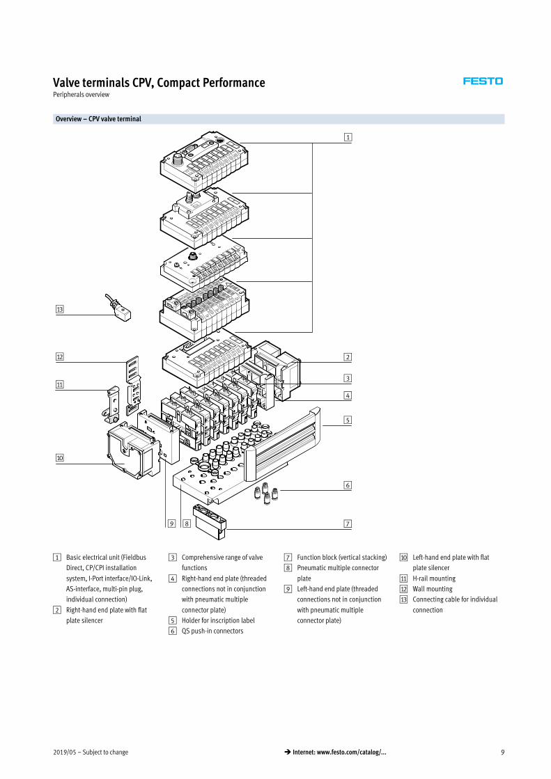
Valve terminals CPV, Compact PerformanceKey features – Pneumatic components
Valve function
Code Circuit symbol Size Description
10 14 18
–
� � �
5/3E function, mid-position exhausted
The valve function “mid-position exhausted” is created using a 2x 3/2-way
valve, normally closed (code C, CK).
� Pneumatic spring return
� Piston spool valve
–
� � �
5/3B function, mid-position pressurised
The valve function “mid-position pressurised” is created using a 2x 3/2-way
valve, normally open (code N, NK).
� Pneumatic spring return
� Piston spool valve
D, DK
� � �
2x 2/2-way valve, single solenoid
� Normally closed
� Pneumatic spring return
� Piston spool valve
� With duct separation 1, 11 for valve DK
� Size 18 only available for valve D
I, IK
� � �
2x 2/2-way valve, single solenoid
� Normal position
– 1x open (control side 12)
– 1x closed (control side 14)
� Pneumatic spring return
� Piston spool valve
� With duct separation 1, 11 for valve IK
� Size 18 only available for valve I
R Relay plate (2 floating contacts)
� � –
A relay plate (code R) with (N/O contacts) can also be used instead of a valve
slice. Each relay plate has two relays for actuating two electrically isolated
outputs. Load capacity: 24�V�DC, 1�A.
� Connecting cable KRP-1-24-…
� An inscription label holder cannot be used

2019/05 – Subject to change 13� Internet: www.festo.com/catalog/...
Valve terminals CPV, Compact PerformanceKey features – Pneumatic components
Additional pneumatic functions
Code Circuit symbol Size Description
10 14 18
A Vacuum generator
� � �
Vacuum generation according to the ejector principle.
Vacuum slices of different widths for different suction capacities.
Combinations with a number of vacuum slices and/or directional control
function slices are possible on the same valve terminal.
In principle, an open connection is formed between the exhaust duct 3/5 and
the working line 4. When the nozzle is not switched, the resulting back pres
sure in the exhaust duct flows back into the working line. When the nozzle is
switched, the vacuum can be greatly reduced by the resulting back pressure.
This effect is improved through optimised exhausting. It does not occur where
there is only one vacuum generator per valve terminal and where separator
plates (code�S) are used for separation.
Vacuum generator on pilot side 14
� Reset via mechanical spring and pneumatic spring
� Ejector pulse on pilot side 12 (code E)
� Note air supply and exhaust when using more than two vacuum generators
E Vacuum generator with ejector pulse
� � �
P Input (valve side)
Output (cylinder side)
� � –
2x one-way flow control valve, supply air flow control
Module (actuator) for direct flange mounting on the CPV valves.
Also suitable for pneumatic multiple connector plates.
Different valve actuators cannot be combined.
Not with valve function G
� Not in first or last valve position with accessories M, P, V
(pneumatic multiple connector plate)
� Cannot be used with accessories GQC and GQD
(pneumatic multiple connector plate)
Q Input (valve side)
Output (cylinder side)
� � –
2x one-way flow control valve, exhaust air flow control
Module (actuator) for direct flange mounting on the CPV valves.
Also suitable for pneumatic multiple connector plates.
Different valve actuators cannot be combined.
� Not with valve function G
� Not in first or last valve position with accessories M, P, V
(pneumatic multiple connector plate)
� Cannot be used with accessories GQC and GQD
(pneumatic multiple connector plate)
V Input (valve side)
Output (cylinder side) � � –
One-way flow control valve for vacuum
The module CPV-…-BS-GRZ-V-… has a built-in non-return valve as well as a flow
control function for adjusting the ejector pulse. The non-return valve serves to
temporarily maintain the vacuum, even if the vacuum generator is switched off.
The module is suitable for vacuum generators (code A, E).
� Not in first or last valve position with accessories M, P, V
(pneumatic multiple connector plate)
� Cannot be used with accessories GQC and GQD
(pneumatic multiple connector plate)

Subject to change – 2019/0514 � Internet: www.festo.com/catalog/...
Valve terminals CPV, Compact PerformanceKey features – Pneumatic components
Creating pressure zones
Different pressures at port 1 and 11
result in two pressure levels per valve.
This means, for example, that a cylin
der drive can be advanced using high
pressure and retracted using low
pressure to save energy.
The maximum number of pressure
zones possible is determined by the
combination of the following
components:
� Use of a separator plate
� End plate pair type
� Valve slice type
� Number of valve slices
The CPV valve terminal can be divided
into 2 to 4 pressure zones with the aid
of separator plates or valves with inte
grated duct separation.
Separator plates/valves with integrated duct separation
Code Graphical symbol Size Note
10 14 18
T Separator plate for creating pressure zones,
supply duct 1 and 11 separated
Pilot exhaust air
Pilot air supply
Exhaust air
Working air
Working air
82/84
12/14
3/5
1
11
� � �
A separator plate (code T) is used to separate the duct for the air supply
(port 1 and 11) to provide two pressure zones.
� Not in first or last valve position
� Not with compressed air supply A, B, C, D, U, V, W, X
S Separator plate for creating pressure zones,
supply duct 1, 11 and exhaust 3/5 separated
82/84
12/14
3/5
1
11
Pilot exhaust air
Pilot air supply
Exhaust air
Working air
Working air
� � �
The separator plate (code S) separates the exhaust duct 3/5 as well as the
supply duct 1 and 11. This plate should be used if one of the pressure zones
is under vacuum to avoid any effects on the vacuum or to prevent back
pressure on neighbouring valve functions.
� Not in first or last valve position
� Not with compressed air supply A, B, C, D, U, V, W, X
(single-side compressed air supply)
L Blanking plate (vacant position)
Pilot exhaust air
Pilot air supply
Exhaust air
Working air
82/84
3/5
1
Working air 11
12/14� � �
A blanking plate (code L) is used to create a vacant position where a valve
can be positioned at a later date.
MK,
JK,
CK,
NK,
DK,
IK
Valve with integrated separation of ducts 1 and 11
Pilot exhaust air
Pilot air supply
Exhaust air
Working air
Working air
82/84
12/14
3/5
1
11
� � –
With these valves the ducts for the air supply (port 1 and 11) are closed to
the right-hand side of the valve with a cast membrane. The advantage of
using this instead of a separator plate is that no valve location is occupied
by a separator plate.
-H- Note
Where internal pilot air via the right-hand end plate is used as the
compressed air supply, at least one further valve with the code M, F, J, C, CY,
N, H, G, D, I, A or E must be used directly to the right of this valve.

2019/05 – Subject to change 15� Internet: www.festo.com/catalog/...
Valve terminals CPV, Compact PerformanceKey features – Pneumatic components
Examples: Compressed air supply
External pilot air supply, flat plate silencer at both ends
Compressed air supply via pneumatic
multiple connector plate:
code H
The diagram opposite shows an
example of the configuration and con
nection of the compressed air supply
with external pilot air supply. Port
12/14 on the pneumatic multiple con
nector plate is equipped with a fitting
for this purpose. Ports 3/5 and 82/84
are vented via the flat plate silencers.
One separating seal each can be
optionally used to create pressure
zones.
Optional separating
seal
Internal pilot air supply, ducted exhaust air or threaded silencer
Compressed air supply via end plates:
code Z
The diagram opposite shows an
example of the configuration and con
nection of the compressed air supply
with internal pilot air supply.
The pilot air is branched at the right-
hand end plate of port 1 or 11. Ports
3/5 and 82/84 are vented via the
threaded silencer.
One separating seal each can be
optionally used to create pressure
zones.
Optional separating
seal
Subject to change – 2019/0516 � Internet: www.festo.com/catalog/...
Valve terminals CPV, Compact PerformanceKey features – Pneumatic components
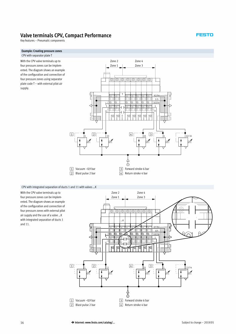
Example: Creating pressure zones
CPV with separator plate T
With the CPV valve terminals up to
four pressure zones can be implem
ented. The diagram shows an example
of the configuration and connection of
four pressure zones using separator
plate code T – with external pilot air
supply.
Zone 2
Zone 1
Zone 4
Zone 3
1 2 4 3
1 Vacuum –0.9 bar
2 Blast pulse 2 bar
3 Forward stroke 6 bar
4 Return stroke 4 bar
CPV with integrated separation of ducts 1 and 11 with valves …K
With the CPV valve terminals up to
four pressure zones can be implem
ented. The diagram shows an example
of the configuration and connection of
four pressure zones with external pilot
air supply and the use of a valve …K
with integrated separation of ducts 1
and 11.
Zone 2
Zone 1
Zone 4
Zone 3
1 2 4 3
1 Vacuum –0.9 bar
2 Blast pulse 2 bar
3 Forward stroke 6 bar
4 Return stroke 4 bar

2019/05 – Subject to change 17� Internet: www.festo.com/catalog/...
Valve terminals CPV, Compact PerformanceKey features – Pneumatic components
Compressed air supply and exhausting
The two end plates that pressurise
and exhaust the valve slices are
a characteristic feature of a CPV valve
terminal:
� Large duct cross sections ensure
maximum flow rates even when
multiple valves are switched in
parallel
� Large flat plate silencers in the end
plates
� Internal/external pilot air supply
Each individual valve is supplied with
compressed air from two individual
ducts (supply ports 1/11) and
exhausted via a large, integrated ex
haust duct (exhaust 3/5). This design
permits unique flexibility and func
tionality. It is the easiest way of realis
ing a number of pressure zones per
terminal or combinations of vacuum
applications.
The valve terminal is supplied via end
plates, either on the left, on the right
or on both sides. End plate combina
tions other than those listed are
possible (on request).
Pilot air supply
Internal pilot air supply External pilot air supply
Internal pilot air supply can be se
lected if the supply pressure at pneu
matic port 1 is 3 … 8 bar. With inter
nal pilot air supply the branch is
located in the left or right-hand end
plate. There is no port 12/14.
External pilot air supply is required if
the supply pressure at pneumatic port
1 is less than 3 bar or greater than
8 bar. In this case, pressure of
3 … 8 bar is applied at port 12/14.
If a gradual pressure build-up in the
system using a pressurised on-off
valve is required, external pilot supply
air should be selected. The control
pressure applied during switch-on is
already very high in this case.
External pilot air supply is also
required if it is necessary to ensure
that the back pressure flaps (valve
order code CY) are closed securely in
the event of a sudden drop in operat
ing pressure or if the operating
pressure is switched off.
End plates
Example of an end plate:
The diagram shows a left-hand end
plate with external pilot air supply.
The exhaust ports 3/5 and 82/84 can
be equipped with fittings or silencers.
An end plate for internal pilot air
supply does not have ports 12/14
and 11.
The port 82/84 is always present
and should be fitted with a silencer.
The port 12/14 is connected internally
with port 1 on an end plate for
internal pilot air supply.
Subject to change – 2019/0518 � Internet: www.festo.com/catalog/...
Valve terminals CPV, Compact PerformanceKey features – Pneumatic components
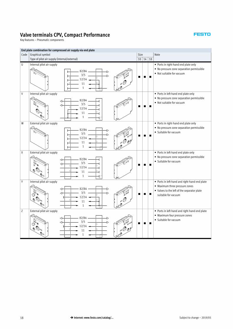
End plate combination for compressed air supply via end plate
Code Graphical symbol
Type of pilot air supply (internal/external)
Size Note
10 14 18
U Internal pilot air supply
82/843/5
12/14
11
1
� � �
� Ports in right-hand end plate only
� No pressure zone separation permissible
� Not suitable for vacuum
V Internal pilot air supply
82/843/5
12/14
11
1
� � �
� Ports in left-hand end plate only
� No pressure zone separation permissible
� Not suitable for vacuum
W External pilot air supply
82/843/5
12/14
11
1
� � �
� Ports in right-hand end plate only
� No pressure zone separation permissible
� Suitable for vacuum
X External pilot air supply
82/843/5
12/14
11
1
� � �
� Ports in left-hand end plate only
� No pressure zone separation permissible
� Suitable for vacuum
Y Internal pilot air supply
82/843/5
12/14
11
1
� � �
� Ports in left-hand and right-hand end plate
� Maximum three pressure zones
� Valves to the left of the separator plate
suitable for vacuum
Z External pilot air supply
82/843/5
12/14
11
1
� � �
� Ports in left-hand and right-hand end plate
� Maximum four pressure zones
� Suitable for vacuum

2019/05 – Subject to change 19� Internet: www.festo.com/catalog/...
Valve terminals CPV, Compact PerformanceKey features – Pneumatic components
End plate combination for compressed air supply via pneumatic multiple connector plate
Code Graphical symbol
Type of pilot air supply (internal/external)
Size Note
10 14 18
Y Internal pilot air supply
82/843/5
12/14
11
1
� � �
� Ports on pneumatic multiple connector plate
� Pressure zone separation only permissible
with separator plate (code T)
� Maximum two pressure zones
� Valves to the left of the separator plate
suitable for vacuum
� Only for accessories M, P, V, GQC, GQD
(pneumatic multiple connector plate)
Z External pilot air supply
82/843/5
12/14
11
1
� � �
� Ports on pneumatic multiple connector plate
� Pressure zone separation only permissible
with separator plate (code T)
� Maximum three pressure zones
� Suitable for vacuum
� Only for accessories M, P, V, GQC, GQD
(pneumatic multiple connector plate)
End plate combination for compressed air supply via end plates with flat plate silencer
Code Graphical symbol
Type of pilot air supply (internal/external)
Size Note
10 14 18
A Internal pilot air supply
82/843/5
12/14
11
1
� � �
� Ports in right-hand end plate
� No pressure zone separation permissible
� Not suitable for vacuum
B Internal pilot air supply
82/843/5
12/14
11
1
� � �
� Ports in left-hand end plate
� No pressure zone separation permissible
� Not suitable for vacuum
C External pilot air supply
82/843/5
12/14
11
1
� � �
� Ports in right-hand end plate
� No pressure zone separation permissible
� Suitable for vacuum
D External pilot air supply
82/843/5
12/14
11
1
� � �
� Ports in left-hand end plate
� No pressure zone separation permissible
� Suitable for vacuum

Subject to change – 2019/0520 � Internet: www.festo.com/catalog/...
Valve terminals CPV, Compact PerformanceKey features – Pneumatic components
End plate combination for compressed air supply via pneumatic multiple connector plate with flat plate silencer
Code Graphical symbol
Type of pilot air supply (internal/external)
Size Note
10 14 18
E External pilot air supply
82/843/5
12/14
11
1
� � �
� Ports on pneumatic multiple connector plate
� Exhaust air vented via flat plate silencer on
the right
� Pressure zone separation only permissible
with separator plate (code T)
� Maximum four pressure zones
� Suitable for vacuum
� Only for accessories M, P, V, GQC, GQD
(pneumatic multiple connector plate)
F External pilot air supply
82/843/5
12/14
11
1
� � �
� Ports on pneumatic multiple connector plate
� Exhaust air vented via flat plate silencer on
the left
� Pressure zone separation only permissible
with separator plate (code T)
� Maximum four pressure zones
� Suitable for vacuum
� Only for accessories M, P, V, GQC, GQD
(pneumatic multiple connector plate)
G Internal pilot air supply
82/843/5
12/14
11
1
� � �
� Ports on pneumatic multiple connector plate
� Exhaust air vented via flat plate silencer on
the left
� Pressure zone separation only permissible
with separator plate (code T)
� Maximum three pressure zones
� Not suitable for vacuum
� Only for accessories M, P, V, GQC, GQD
(pneumatic multiple connector plate)
H External pilot air supply
82/843/5
12/14
11
1
� � �
� Ports on pneumatic multiple connector plate
� Exhaust air vented via flat plate silencers at
both ends
� Pressure zone separation permissible
� Suitable for vacuum
� Only for accessories M, P, V, GQC, GQD
(pneumatic multiple connector plate)
J Internal pilot air supply
82/843/5
12/14
11
1
� � �
� Ports on pneumatic multiple connector plate
� Exhaust air vented via flat plate silencers at
both ends
� Pressure zone separation permissible
� Maximum three pressure zones
� Valves to the left of the separator plate
suitable for vacuum
� Only for accessories M, P, V, GQC, GQD
(pneumatic multiple connector plate)
K Internal pilot air supply
82/843/5
12/14
11
1
� � �
� Ports on pneumatic multiple connector plate
� Exhaust air vented via flat plate silencer on
the right
� Pressure zone separation permissible
� Maximum three pressure zones
� Suitable for vacuum in combination
with separator plate
� Only for accessories M, P, V, GQC, GQD
(pneumatic multiple connector plate)

2019/05 – Subject to change 21� Internet: www.festo.com/catalog/...
Valve terminals CPV, Compact PerformanceKey features – Pneumatic components
Pneumatic connection
The working lines are located directly
in the valve slices. Threaded
connectors and Quick Star push-in
fittings (QS) are available for different
tubing sizes. The supply ports are
located in the end plates or in the
pneumatic multiple connector plate.
Push-in fittings are available fully
assembled.
The following working lines
can be selected:
� Large push-in connectors: code A
� Small push-in connectors: code B
� Threaded connectors: code C
Connection sizes for the threaded and
QS push-in fittings can be found in
the table below.
Pneumatic multiple connector plate
One-piece “connection plates” that
contain both working lines and supply
ports can be combined with a pneu
matic multiple connector plate. This
enables the valve terminal as a pneu
matic “function” to be separated from
the valve ports.
The pneumatic multiple connector
plate enables different mounting
options from wall mounting to direct
passage through a cabinet wall.
Easy-to-service and flexible
connection technology thanks
to the following:
� Common connection via the
pneumatic multiple connector plate
with all connections on one side
� The valve terminal can be
assembled/disassembled using
only four screws, whereby the
pneumatics remain fully connected
� Quick assembly/disassembly
� No errors when recommissioning as
a result of incorrect connection of
tubing
CPV valve terminal Pneumatic multiple connector plate
4
2 3/5
12/14
82/84
11
1
1
2
4
11
Connection sizes
Connection to ISO 5599 CPV10 CPV14 CPV18 Comment
1/11 Working air G1/8 G1/4 G3/8 Fitting in end plate or pneumatic multiple connector
plate
2/4 Working line M7 (QS6/QS4) G1/8 (QS8/QS6) G1/4 (QS10/QS8) Connection in valve slice, connection for push-in fitting
in brackets
3/5 Exhaust air port G3/8 G1/2 G1/2 Via right-hand/left-hand end plate
G1/4 G3/8 G1/2 Pneumatic multiple connector plate
12/14 Pilot air supply port M5 G1/8 G1/4 Fitting in end plate or pneumatic multiple connector
plate
82/84 Pilot exhaust air port M5 G1/8 G1/4 Via right-hand/left-hand end plate
M7 (M5)1) G1/8 G1/4 Pneumatic multiple connector plate
1) With flanged pneumatic multiple connector plate

Subject to change – 2019/0522 � Internet: www.festo.com/catalog/...
Valve terminals CPV, Compact PerformanceKey features – Pneumatic components
Pneumatic connection: fitting set for compressed air supply
Code for
compressed air
supply
Port Designation Size 10
QS6
Type
Size 14
QS8
Type
Size 18
QS10
Type
Without pneumatic multiple connector plate
U, V 82/84 Silencer AMTE-M-LH-M5 U-1/8-B U-1/4-B
3/5 Silencer U-3/8-B U-1/2-B U-1/2-B
1 Push-in fitting QS-1/8-8-I QS-1/4-10-I QS-3/8-12-I
W, X 82/84 Silencer AMTE-M-LH-M5 U-1/8-B U-1/4-B
3/5 Silencer U-3/8-B U-1/2-B U-1/2-B
1 Push-in fitting QS-1/8-8-I QS-1/4-10-I QS-3/8-12-I
12/14 Push-in fitting QSM-M5-6-I QS-1/8-8-I QS-1/4-10-I
Y 82/84 on right Silencer AMTE-M-LH-M5 U-1/8-B U-1/4-B
82/84 on left Blanking plug B-M5 B-1/8 B-1/4
3/5 on right Silencer U-3/8-B U-1/2-B U-1/2-B
3/5 on left Blanking plug B-3/8 B-1/2 B-1/2
1/11 on left Push-in fitting QS-1/8-8-I QS-1/4-10-I QS-3/8-12-I
Z 82/84 on right Silencer AMTE-M-LH-M5 U-1/8-B U-1/4-B
82/84 on left Blanking plug B-M5 B-1/8 B-1/4
3/5 on right Silencer U-3/8-B U-1/2-B U-1/2-B
3/5 on left Blanking plug B-3/8 B-1/2 B-1/2
12/14 on right Push-in fitting QSM-M5-6-I QS-1/8-8-I QS-1/4-10-I
12/14 on left Blanking plug B-M5 B-1/8 B-1/4
1/11 Push-in fitting QS-1/8-8-I QS-1/4-10-I QS-3/8-12-I
With pneumatic multiple connector plate; code M
Y 82/84 Silencer UC-M7 U-1/8-B U-1/4-B
12/14 Blanking plug B-M7 B-1/8 B-1/4
3/5 Silencer U-1/4-B U-3/8-B U-1/2-B
1/11 on left Push-in fitting QS-1/8-8-I QS-1/4-10-I QS-3/8-12-I
11 on right Blanking plug B-1/8 B-1/4 B-3/8
Z 82/84 Silencer UC-M7 U-1/8-B U-1/4-B
3/5 Silencer U-1/4-B U-3/8-B U-1/2-B
12/14 Push-in fitting QSM-M7-6-I QS-1/8-8-I QS-1/4-10-I
1/11 on left Push-in fitting QS-1/8-8-I QS-1/4-10-I QS-3/8-12-I
With pneumatic multiple connector plate; code P, GQC
Y 82/84 Silencer AMTE-M-LH-M5 U-1/8-B U-1/4-B
12/14 Blanking plug B-M5 B-1/8 B-1/4
3/5 Silencer U-1/4-B U-3/8-B U-1/2-B
1/11 on left Push-in fitting QS-1/8-8-I QS-1/4-10-I QS-3/8-12-I
11 on right Blanking plug B-1/8 B-1/4 B-3/8
Z 82/84 Silencer AMTE-M-LH-M5 U-1/8-B U-1/4-B
3/5 Silencer U-1/4-B U-3/8-B U-1/2-B
12/14 Push-in fitting QSM-M5-6-I QS-1/8-8-I QS-1/4-10-I
1/11 on left Push-in fitting QS-1/8-8-I QS-1/4-10-I QS-3/8-12-I

2019/05 – Subject to change 23� Internet: www.festo.com/catalog/...
Valve terminals CPV, Compact PerformanceKey features – Pneumatic components
Pneumatic connection: fitting set for compressed air supply
Code for
compressed air
supply
Port Designation Size 10
QS6
Type
Size 14
QS8
Type
Size 18
QS10
Type
Without pneumatic multiple connector plate
A, B 82/84 Blanking plug B-M5 B-1/8 B-1/4
3/5 Blanking plug B-3/8 B-1/2 B-1/2
1 Push-in fitting QS-1/8-8-I QS-1/4-10-I QS-3/8-12-I
C, D 82/84 Blanking plug B-M5 B-1/8 B-1/4
3/5 Blanking plug B-3/8 B-1/2 B-1/2
1 Push-in fitting QS-1/8-8-I QS-1/4-10-I QS-3/8-12-I
12/14 Push-in fitting QSM-M5-6-I QS-1/8-8-I QS-1/4-10-I
With pneumatic multiple connector plate; code M
E, F, H 82/84 Blanking plug B-M7 B-1/8 B-1/4
3/5 Blanking plug B-1/4 B-3/8 B-1/2
1/11 Push-in fitting QS-1/8-8-I QS-1/4-10-I QS-3/8-12-I
12/14 Push-in fitting QSM-M7-6-I QS-1/8-8-I QS-1/4-10-I
G, J, K 82/84 Blanking plug B-M7 B-1/8 B-1/4
3/5 Blanking plug B-1/4 B-3/8 B-1/2
On right in 1, left Push-in fitting QS-1/8-8-I QS-1/4-10-I QS-3/8-12-I
On right in 11 Blanking plug B-1/8 B-1/4 B-3/8
12/14 Blanking plug B-M7 B-1/8 B-1/4
With pneumatic multiple connector plate; code P, GQC
E, F, H 82/84 Blanking plug B-M5 B-1/8 B-1/4
3/5 Blanking plug B-1/4 B-3/8 B-1/2
1/11 Push-in fitting QS-1/8-8-I QS-1/4-10-I QS-3/8-12-I
12/14 Push-in fitting QSM-M5-6-I QS-1/8-8-I QS-1/4-10-I
G, J, K 82/84 Blanking plug B-M5 B-1/8 B-1/4
3/5 Blanking plug B-1/4 B-3/8 B-1/2
On right in 1, left Push-in fitting QS-1/8-8-I QS-1/4-10-I QS-3/8-12-I
On right in 11 Blanking plug B-1/8 B-1/4 B-3/8
12/14 Blanking plug B-M5 B-1/8 B-1/4
Subject to change – 2019/0524 � Internet: www.festo.com/catalog/...
Valve terminals CPV, Compact PerformanceKey features – Pneumatic components
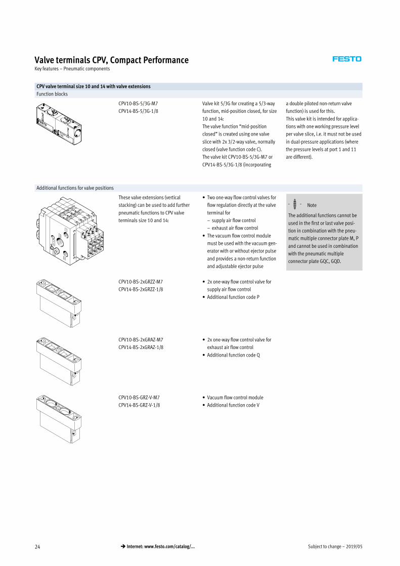
CPV valve terminal size 10 and 14 with valve extensions
Function blocks
CPV10-BS-5/3G-M7
CPV14-BS-5/3G-1/8
Valve kit 5/3G for creating a 5/3-way
function, mid-position closed, for size
10 and 14:
The valve function “mid-position
closed” is created using one valve
slice with 2x 3/2-way valve, normally
closed (valve function code C).
The valve kit CPV10-BS-5/3G-M7 or
CPV14-BS-5/3G-1/8 (incorporating
a double piloted non-return valve
function) is used for this.
This valve kit is intended for applica
tions with one working pressure level
per valve slice, i.e. it must not be used
in dual-pressure applications (where
the pressure levels at port 1 and 11
are different).
Additional functions for valve positions
These valve extensions (vertical
stacking) can be used to add further
pneumatic functions to CPV valve
terminals size 10 and 14:
� Two one-way flow control valves for
flow regulation directly at the valve
terminal for
– supply air flow control
– exhaust air flow control
� The vacuum flow control module
must be used with the vacuum gen
erator with or without ejector pulse
and provides a non-return function
and adjustable ejector pulse
-H- Note
The additional functions cannot be
used in the first or last valve posi
tion in combination with the pneu
matic multiple connector plate M, P
and cannot be used in combination
with the pneumatic multiple
connector plate GQC, GQD.
CPV10-BS-2xGRZZ-M7
CPV14-BS-2xGRZZ-1/8
� 2x one-way flow control valve for
supply air flow control
� Additional function code P
CPV10-BS-2xGRAZ-M7
CPV14-BS-2xGRAZ-1/8
� 2x one-way flow control valve for
exhaust air flow control
� Additional function code Q
CPV10-BS-GRZ-V-M7
CPV14-BS-GRZ-V-1/8
� Vacuum flow control module
� Additional function code V
2019/05 – Subject to change 25� Internet: www.festo.com/catalog/...
Valve terminals CPV, Compact PerformanceKey features – Assembly
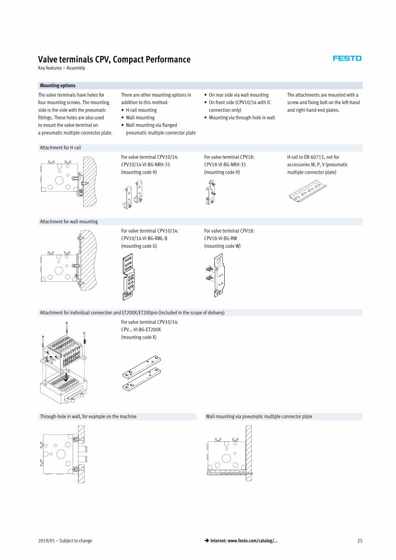
Mounting options
The valve terminals have holes for
four mounting screws. The mounting
side is the side with the pneumatic
fittings. These holes are also used
to mount the valve terminal on
a pneumatic multiple connector plate.
There are other mounting options in
addition to this method:
� H-rail mounting
� Wall mounting
� Wall mounting via flanged
pneumatic multiple connector plate
� On rear side via wall mounting
� On front side (CPV10/14 with IC
connection only)
� Mounting via through-hole in wall
The attachments are mounted with a
screw and fixing bolt on the left-hand
and right-hand end plates.
Attachment for H-rail
For valve terminal CPV10/14:
CPV10/14-VI-BG-NRH-35
(mounting code H)
For valve terminal CPV18:
CPV18-VI-BG-NRH-35
(mounting code H)
H-rail to EN 60715, not for
accessories M, P, V (pneumatic
multiple connector plate)
Attachment for wall mounting
For valve terminal CPV10/14:
CPV10/14-VI-BG-RWL-B
(mounting code U)
For valve terminal CPV18:
CPV18-VI-BG-RW
(mounting code W)
Attachment for individual connection and ET200X/ET200pro (included in the scope of delivery)
For valve terminal CPV10/14:
CPV…-VI-BG-ET200X
(mounting code X)
Through-hole in wall, for example on the machine Wall mounting via pneumatic multiple connector plate
Subject to change – 2019/0526 � Internet: www.festo.com/catalog/...
Valve terminals CPV, Compact PerformanceKey features – Assembly
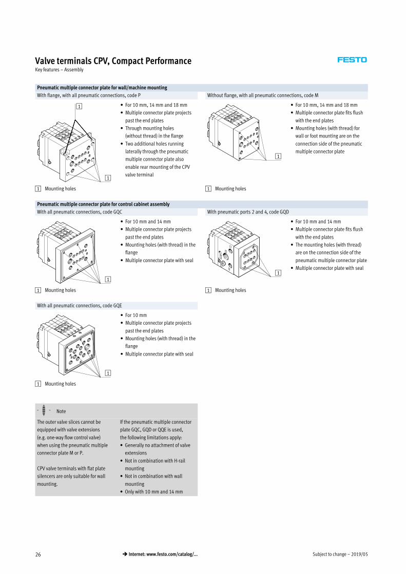
Pneumatic multiple connector plate for wall/machine mounting
With flange, with all pneumatic connections, code P Without flange, with all pneumatic connections, code M
1
1 � For 10 mm, 14 mm and 18 mm
� Multiple connector plate projects
past the end plates
� Through mounting holes
(without thread) in the flange
� Two additional holes running
laterally through the pneumatic
multiple connector plate also
enable rear mounting of the CPV
valve terminal
1
� For 10 mm, 14 mm and 18 mm
� Multiple connector plate fits flush
with the end plates
� Mounting holes (with thread) for
wall or foot mounting are on the
connection side of the pneumatic
multiple connector plate
1 Mounting holes 1 Mounting holes
Pneumatic multiple connector plate for control cabinet assembly
With all pneumatic connections, code GQC With pneumatic ports 2 and 4, code GQD
1
� For 10 mm and 14 mm
� Multiple connector plate projects
past the end plates
� Mounting holes (with thread) in the
flange
� Multiple connector plate with seal
1
� For 10 mm and 14 mm
� Multiple connector plate fits flush
with the end plates
� The mounting holes (with thread)
are on the connection side of the
pneumatic multiple connector plate
� Multiple connector plate with seal
1 Mounting holes 1 Mounting holes
With all pneumatic connections, code GQE
1
� For 10 mm
� Multiple connector plate projects
past the end plates
� Mounting holes (with thread) in the
flange
� Multiple connector plate with seal
1 Mounting holes
-H- Note
The outer valve slices cannot be
equipped with valve extensions
(e.g. one-way flow control valve)
when using the pneumatic multiple
connector plate M or P.
CPV valve terminals with flat plate
silencers are only suitable for wall
mounting.
If the pneumatic multiple connector
plate GQC, GQD or QQE is used,
the following limitations apply:
� Generally no attachment of valve
extensions
� Not in combination with H-rail
mounting
� Not in combination with wall
mounting
� Only with 10 mm and 14 mm

2019/05 – Subject to change 27� Internet: www.festo.com/catalog/...
Valve terminals CPV, Compact PerformanceKey features – Display and operation
Manual override
Three types of manual override are
available:
� Non-detenting via slide
� Detenting
� Blocked
Subsequent conversion of the manual
override from non-detenting to detent
ing or blocked is possible at any time.
The locking clip on the valve must be
removed to this end. This is only
possible after the individual valve has
been removed or the tie rod of the
valve terminal has been released.
-H- Note
See the manual for instructions.
Code Graphical symbol Size Note
10 14 18
N Manual override, non-detenting
� � �
In the “non-detenting” version, the blue slide is held via a locking clip.
A pointed object (e.g. pen, etc.) can be used to activate the manual override
through the opening.
R Manual override, detenting
� � �
In the “detenting” version, the locking clip is removed and the manual
override is activated by pushing the slide down. The non-detenting function
can be re-established by re-installing the locking clip.
V Manual override, blocked
� � �
In the “blocked” version, non-detenting and detenting activation of the
manual override is prevented by means of a cover. Like the non-detenting
locking clip, this cover can be added subsequently, but then remains on
the valve.

Subject to change – 2019/0528 � Internet: www.festo.com/catalog/...
Valve terminals CPV, Compact PerformanceKey features – Display and operation
Display and operation
You will find the following LEDs for
displaying the switching status on the
electrical connections of the CPV valve
terminal:
� Display of the switching status of
the pilot solenoid coil 12 for outlet
port 2
� Display of the switching status of
the pilot solenoid coil 14 for outlet
port 4
� Readable from the “top” as well as
from the “front”
The individual connection has an LED
in the connector plug to display the
switching status.
Inscription labels
� Clip with inscription field on
connection plug (with individual
connection)
� Inscription clips on connection
node (multi-pin plug, AS-interface,
CP installation system, Fieldbus
Direct)
CPV valve manifold with individual connection CPV valve terminal with multi-pin plug connection
1
4
5
63
4
2
7
3
1 Pre-assembled connecting cable
for each pilot solenoid coil
2 Slot for inscription label
3 Yellow LED, signal status display
for pilot solenoid coils (for each
connecting cable)
4 Earth terminal
5 Terminal lugs for solenoid coil 14
6 Terminal lugs for solenoid coil
12
7 Sub-D multi-pin plug (9-pin for
valve terminals with 4 valves,
25-pin for valve terminals with 6
or 8 valves)
Identification system
Inscription label holder
Inscription labels
type IBS 6x10
Inscription labels
type IBS-6x10 for CPV10/14
type IBS 9x20 for CPV18
Transparent inscription label
holder for paper labels (readable
from both sides)
Inscription labels can be affixed as
follows:
� On the top of the electrical base
unit
� On the inscription label holder
The inscription label holder permits
the addition of inscription labels, pro
tects the manual overrides and pre
vents them from being accidentally
activated. The inscription labels are
used to record additional information
regarding the valves.
The inscription label holders can be
ordered together with the valve ter
minal using the order code. The rel
evant inscription labels are supplied
in a frame and are ordered separately.
The inscription label holder cannot be
used together with the relay plate.
Transparent inscription label holder
The transparent inscription label
holder CPV…-VI-ST-… offers a further
labelling option, for example for large
paper labels that can be read from
both sides.
-H- Note
The Word templates for CPV label
holders can be found at:
www.festo.com

2019/05 – Subject to change 29� Internet: www.festo.com/catalog/...
Valve terminals CPV, Compact PerformanceKey features – Electrical components
Electrical connection Electrical power
Contacts that are fitted on the top of
the valve slices form the interface for
various electrical connection options.
The electrical connection is attached
from above using four screws. This
means that the valve terminal can be
adapted to different electrical require
ments or fieldbus protocols using the
same pneumatic part.
t [ms]
I [m
A]
CPV10/14 valves are actuated by
means of an integrated current reduc
tion circuit, which reduces power
consumption and heat build-up. This
current reduction circuit is integrated
in the basic electrical unit (multi-pin
plug or fieldbus connection) or in the
connecting cable.
During switch-off, the voltage peaks
are limited to 38 V DC.
Individual connection
With an individual connection
integration is only carried out in the
pneumatic part, the solenoid valves
are connected with individual cables.

Subject to change – 2019/0530 � Internet: www.festo.com/catalog/...
Valve terminals CPV, Compact PerformanceKey features – Electrical components
Dimensions – Connecting cable for individual connection Download CAD data � www.festo.com
KMYZ-7-24-… KMEB-2-24-…-LED
1 Mounting screw
2 Wire end sleeve
3 Cable, depending on order 1 LED illuminated area
2 Inscription label IBS-9x20
Part No. 18182
3 3-wire cable 2.5 or 5 m
(3x 0.75 mm2)
4 Connection pattern to
EN 175301-803, type C
5 M2.5 screw, captive,
threaded head: Z-combi
cross-slot screws to EN 7045
Type B1 D1 H1 H2 L1 L2 L3 L5
NEBV-Z3WA2L-… 9.7 2.9 12.4 – 26.9 19 50 8.4
KMEB-2-24-2,5-LED 16 7 26 22 2500 34.6 16 –
KMEB-2-24-5-LED 5000
Dimensions – Connecting cable for relay plate Download CAD data � www.festo.com
KRP-1-24-…
2 Location for inscription labels
(order code IBS 6x10,
Part No. 18576)
3 Cable, depending on order
5 Mounting screw
(self-tapping KB 1.8x9)
Type B1 D1 H1 H2 L2 L3
KRP-1-24-… 9.8 3.4 16.4 12 28.3 18
2019/05 – Subject to change 31� Internet: www.festo.com/catalog/...
Valve terminals CPV, Compact PerformanceKey features – Electrical components
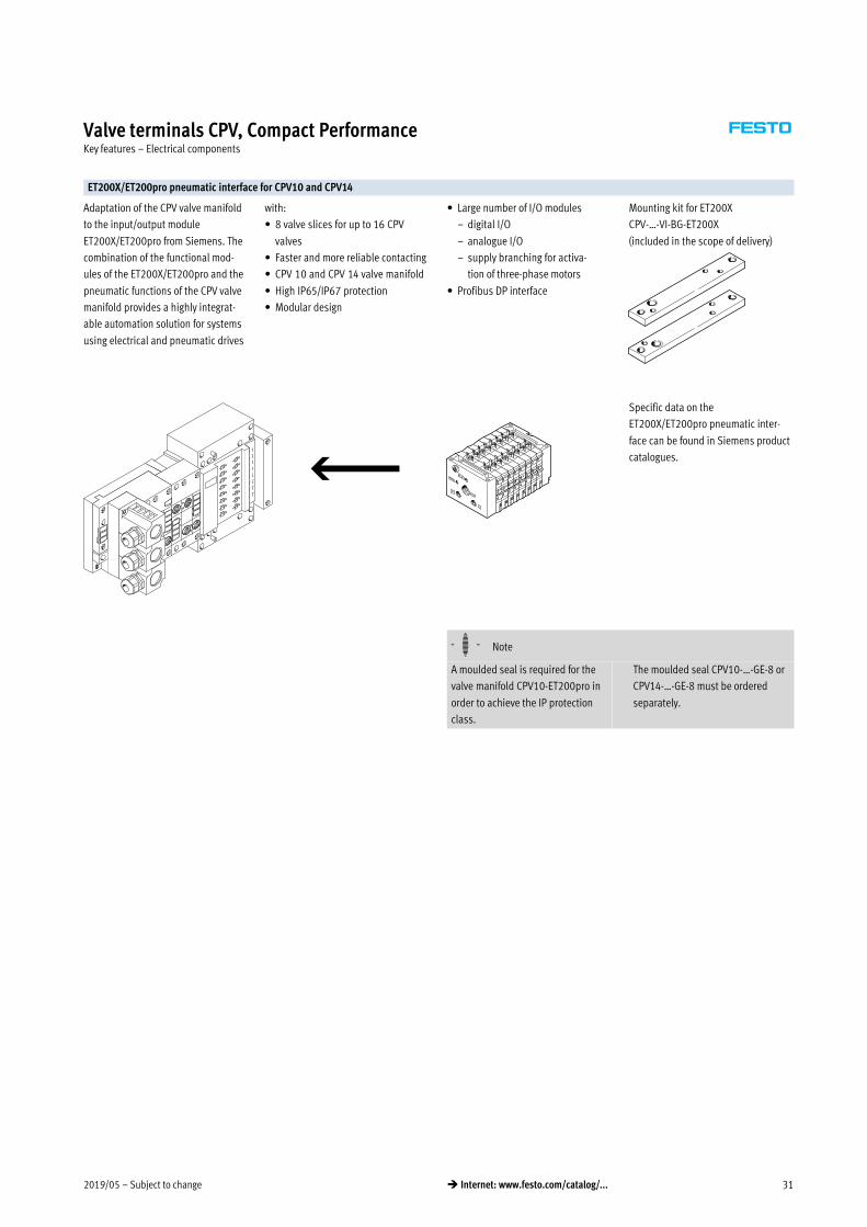
ET200X/ET200pro pneumatic interface for CPV10 and CPV14
Adaptation of the CPV valve manifold
to the input/output module
ET200X/ET200pro from Siemens. The
combination of the functional mod
ules of the ET200X/ET200pro and the
pneumatic functions of the CPV valve
manifold provides a highly integrat
able automation solution for systems
using electrical and pneumatic drives
with:
� 8 valve slices for up to 16 CPV
valves
� Faster and more reliable contacting
� CPV�10 and CPV�14 valve manifold
� High IP65/IP67 protection
� Modular design
� Large number of I/O modules
– digital I/O
– analogue I/O
– supply branching for activa
tion of three-phase motors
� Profibus DP interface
Mounting kit for ET200X
CPV-…-VI-BG-ET200X
(included in the scope of delivery)
Specific data on the
ET200X/ET200pro pneumatic inter
face can be found in Siemens product
catalogues.
-H- Note
A moulded seal is required for the
valve manifold CPV10-ET200pro in
order to achieve the IP protection
class.
The moulded seal CPV10-…-GE-8 or
CPV14-…-GE-8 must be ordered
separately.

Subject to change – 2019/0532 � Internet: www.festo.com/catalog/...
Valve terminals CPV, Compact PerformanceKey features – Electrical components
Multi-pin plug connection
In addition to pneumatic integration,
a multi-pin plug connection also pro
vides integration of the electrical side
and facilitates connection to the
control cabinet and the valve terminal
via a single cable.
Sub-D 9-pin and 25-pin plugs are
used for connection. The plug housing
of the KMP-…- cable provides the
Sub-D connectors with IP65
protection.
The following sizes of plug connector
are used:
� 4-valve valve terminal: 9-pin
� 6-valve valve terminal: 25-pin
� 8-valve valve terminal: 25-pin
Prefabricated connecting cables are
available for easy connection.
Standard lengths of 5�m and 10�m
can be supplied. The pre-assembled
connecting cables are also available
in a design suitable for use with
energy chains.
The cable KMP6-… can alternatively
be used for applications with IP40
protection.
Pin allocation – Pre-assembled multi-pin cable (viewed from plug-in direction)
Plug view Pin Wire colour Valve 24 V DC
Cable KMP3-25P-16… or KMP4-25P… with 25-pin Sub-D plug for 6-valve and 8-valve valve terminal
1 White 1 14
2 Green 12
3 Yellow 2 14
4 Grey 12
5 Pink 3 14
6 Blue 12
7 Red 4 14
8 Purple 12
9 Grey-pink 5 14
10 Red-blue 12
11 White-green 6 14
12 Brown-green 12
13 White-yellow 7 14
14 Yellow-brown 12
15 White-grey 8 14
16 Grey-brown 12
17 White-pink (KMP4 only)
18 Pink-brown (KMP4 only)
19 White-blue (KMP4 only)
20 Brown-blue (KMP4 only)
21 White-red (KMP4 only)
22 Brown-red (KMP4 only)
23 White-black (KMP4 only)
24 Brown (0 V)1)
25 Black (0 V)1)
Cable KMP3-9P… or KMP4-9P… with 9-pin Sub-D plug for 4-valve valve terminal
1 White 1 14
2 Green 12
3 Yellow 2 14
4 Grey 12
5 Pink 3 14
6 Blue 12
7 Red 4 14
8 Purple 12
9 Black Common
1) 0 V for positive switching control signals; connect 24 V for negative switching control signals; mixed operation is not permitted.

2019/05 – Subject to change 33� Internet: www.festo.com/catalog/...
Valve terminals CPV, Compact PerformanceKey features – Electrical components
Pin allocation – Pre-assembled multi-pin cable (viewed from plug-in direction)
Plug view Pin Wire colour Valve 24 V DC
Cable KMP6-25P-20… with 25-pin Sub-D plug for 6-valve and 8-valve valve terminals
1 White 1 14
2 Brown 12
3 Green 2 14
4 Yellow 12
5 Grey 3 14
6 Pink 12
7 Blue 4 14
8 Red 12
9 Black 5 14
10 Purple 12
11 Grey-pink 6 14
12 Red-blue 12
13 White-green 7 14
14 Brown-green 12
15 White-yellow 8 14
16 Yellow-brown 12
17 White-grey
18 Grey-brown
19 White-pink
20 Pink-brown
21 White-blue1)
22 Brown-blue1)
23 White-red1)
24 Brown-red1) (0 V)2)
25 White-black1) (0 V)2)
Cable KMP6-9P-20… with 9-pin Sub-D plug for 4-valve valve terminals
1 White 1 14
2 Brown 12
3 Green 2 14
4 Yellow 12
5 Grey 3 14
6 Pink 12
7 Blue 4 14
8 Red 12
9 Black Common
1) Wire cross section 0.34 mm2
2) 0 V for positive switching control signals; connect 24 V for negative switching control signals; mixed operation is not permitted.
-H- Note
Two threaded sleeves (NEAU-TA-M35-U4,
� p. 63) are required to secure the
multi-pin cable MKP6.

Subject to change – 2019/0534 � Internet: www.festo.com/catalog/...
Valve terminals CPV, Compact PerformanceKey features – Electrical components
Valve terminal CPV – AS-interface valve terminal
The AS-interface facilitates wide rang
ing physical distribution of individual
components or small component
groups.
The AS-interface connection of valve
terminal CPV can be used to control 2,
4, 8 solenoid coils.
The valve terminal cover contains the
LEDs that indicate the operating status
and the protective circuit for the
valves.
The AS-interface protocol standard
permits a maximum of 4 inputs and
4 outputs in one unit. The use of 2 AS-
interface slaves in one valve terminal
means that 8 inputs and 8 outputs
can be controlled in an 8-valve valve
terminal (8 solenoid coils).
All CPV valve terminals can be
operated using additional functions,
e.g. relay plates or vacuum generators.
Valve terminals CPV with inputs are
also available for A/B operation to
SPEC 2.1 and 3.0.
AS-interface control
� For 2, 4 or 8 valves
� Great variety thanks to the wide
range of modules in the system
AS-interface with A/B operation
� For 3 or 4 and/or 6 or 8 valves
depending on the specification
� All the benefits of the simple
installation system are retained
� 100% more inputs/master
� 50% more outputs/master
� Improved peripheral error
diagnostics
� More AS-interface functions in
Specifications 2.1 and 3.0
� Internet: as-interface
AS-interface valve terminal with auxiliary power supply AS-interface valve terminal with auxiliary power supply and inputs

2019/05 – Subject to change 35� Internet: www.festo.com/catalog/...
Valve terminals CPV, Compact PerformanceKey features – Electrical components
I-Port interface/IO-Link
The I-Port interface/IO-Link enables
the valve terminal CPV to be connec
ted to the following systems:
� I-Port master from Festo
(CPX terminal, CECC)
� Fieldbus node CTEU from Festo
� IO-Link master
A maximum of 16 solenoid coils can
be actuated distributed over a
maximum of 8 valve positions.
The maximum distance between the
I-Port/IO-Link master and valve ter
minal with I-Port interface/IO-Link is
20 m.
The 5-pin connecting cables contain
the power supply for the valves, sep
arate from this is the power supply for
the internal valve terminal electronics
and the control signals.
The valve terminal cover contains the
LEDs that indicate the operating
status and the protective circuit for
the valves.
All valve terminals CPV can be oper
ated with other functions such as
relay plates or vacuum generators.
� Internet: cteu
� Internet: cpx
� Internet: cecc
CPV valve terminal with I-Port interface/IO-Link CPV valve terminal with I-Port interface with fieldbus node
CP/CPI installation system, valve terminal
11
The integration of valve terminal CPV
into a fieldbus system or independent
control system is accomplished by
connecting the terminal to the corre
sponding fieldbus node or control
block with simple, pre-assembled ter
minal connectors.
The installation system integrates the
valve terminal CPV and various I/O
modules, etc. into a single installation
concept.
The 5-pin connecting cables carry the
supply power and control signals.
The valve terminal cover contains the
LEDs that indicate the operating
status and the protective circuits for
the valves.
� Max. 8 valve slices for up to 16 CPV
valves
The CP string is used to exchange the
input and output states of the con
nected modules with the CP fieldbus
node.
� Internet: ctec

Subject to change – 2019/0536 � Internet: www.festo.com/catalog/...
Valve terminals CPV, Compact PerformanceInstructions for use
Fieldbus Direct valve terminal
Fieldbus Direct is a system for
connecting one valve terminal to nine
different fieldbus standards. The most
important systems, including
PROFIBUS, INTERBUS, DeviceNet and
CANopen, are supported.
The CP string extension option en
ables the functions and components
of the CPI installation system to be
used.
The optional string extension permits
additional valve terminals and I/O
modules with CP/CPI function to be
connected to the Fieldbus Direct
fieldbus node.
Depending on the version, the valve
terminals are available in all three
sizes, 10, 14 and 18 mm, each with
8 valve slices.
Equipment
Operate system equipment with unlu
bricated compressed air if possible.
Festo valves and cylinders are de
signed so that, if used as designated,
they will not require additional lu
brication and will still achieve a long
service life.
The quality of compressed air down
stream of the compressor must corre
spond to that of unlubricated com
pressed air. If possible, do not oper
ate all your system equipment with
lubricated compressed air. The lubri
cators should, where possible, always
be installed directly upstream of the
actuator used.
Incorrect additional oil and too high
an oil content in the compressed air
reduce the service life of the valve
terminal.
Use Festo special oil OFSW-32 or the
alternatives listed in the Festo
catalogue (as specified in DIN 51524
HLP32; basic oil viscosity 32 CST
at 40°C).
Bio-oils
When using bio-oils (oils based on
synthetic or native ester, e.g. ra
peseed oil methyl ester), the maxi
mum residual oil content of
0.1 mg/m3 must not be exceeded
(see ISO 8573-1 Class 2).
Mineral oils
When using mineral oils (e.g. HLP oils
to DIN 51524, parts 1 to 3) or similar
oils based on poly-alpha-olefins
(PAO), the maximum residual oil con
tent of 5 mg/m3 must not be exceeded
(see ISO 8573-1 Class 4).
A higher residual oil content irrespec
tive of the compressor oil cannot be
permitted, as the basic lubricant
would be flushed out over time.

2019/05 – Subject to change 37� Internet: www.festo.com/catalog/...
Valve terminals CPV, Compact PerformanceTechnical data
-M- Flow rate up toCPV10: 400 l/min
CPV14: 800 l/min
CPV18: 1600 l/min
-K- Valve widthCPV10: 10 mm
CPV14: 14 mm
CPV18: 18 mm
-P- Voltage24 V DC
General technical data
CPV10 CPV14 CPV18
Design Electromagnetically actuated piston spool valve
Lubrication Life-time lubrication, PWIS-free (free of paint-wetting impairment substances)
Type of mounting Via pneumatic multiple connector plate
Via backwall
On H-rail
Mounting position Any
Lap Overlap
Manual override Non-detenting/detenting/blocked
Width [mm] 10 14 18
Nominal size [mm] 4 6 8
Nominal flow rate without fitting [l/min] 400 800 1600
14003)
b value 0.4 0.42
0.372)
0.38
0.412)
0.403)
c value [l/sbar] 1.6 3.2 6.3
5.663)
Pneumatic connections1)
Pneumatic connection Via end plate or pneumatic multiple connector plate
Supply port 1/11 G1/8 G1/4 G3/8
Exhaust port 3/5 G3/8 (G1/4) G1/2 (G3/8) G1/2
Working ports 2/4 M7 G1/8 G1/4
Pilot air supply port 12/14 M5 (M7) G1/4 G1/4
Pilot exhaust air port 82/84 M5 (M7) G1/8 G1/4
1) Connection dimensions in brackets for pneumatic multiple connector plate
2) Values for 2x 2/2-way valve
3) Values for 5/3-way valve with mechanical spring return
Safety characteristics
CPV10 CPV14 CPV18
Proven component Yes
Max. positive test pulse with 0 signal [ìs] 1400 1400 1900
Max. negative test pulse with 1 signal [ìs] 700 400 1700
Shock resistance Shock test with severity level 2, to EN 60068-2-27
Vibration resistance Transport application test with severity level 2, to EN 60068-2-6

Subject to change – 2019/0538 � Internet: www.festo.com/catalog/...
Valve terminals CPV, Compact PerformanceTechnical data
Operating and environmental conditions
Valve function order code M, MK F J, JK N, NK C, CK CY H, HK G D, DK I, IK A E
Operating medium Compressed air to ISO 8573-1:2010 [7:4:4] � page 36
Note on operating/pilot medium Lubricated operation possible (in which case lubricated operation will always be required)
Operating pressure [bar] –0.9 … +10 +0.1 … +10 –0.9 … +10
Operating pressure for valve terminal
with internal pilot air supply
[bar] 3 … 8
Pilot pressure [bar] 3 … 8
Ambient temperature [°C] –5 … +50 (vacuum generators: 0 … +50)
Temperature of medium [°C] –5 … +50 (vacuum generators: 0 … +50)
Storage temperature [°C] –20 … +40
Relative air humidity at 25 °C [%] 95 with no condensation
Corrosion resistance class CRC1) 2 1
Note on materials RoHS-compliant
1) Corrosion resistance class CRC 1 to Festo standard FN 940070
Low corrosion stress. For dry indoor applications or transport and storage protection. Also applies to parts behind covers, in the non-visible interior area, and parts which are covered in the application (e.g. drive
trunnions).
Corrosion resistance class CRC 2 to Festo standard FN 940070
Moderate corrosion stress. Indoor applications in which condensation may occur. External visible parts with primarily decorative requirements for the surface and which are in direct contact with the ambient atmo
sphere typical for industrial applications.
ATEX
ATEX category for gas II 3G
Type of ignition protection for gas Ex nA IIC T4 X Gc
ATEX category for dust –5 ≤ Ta ≤ +50
Certification c UL us Recognized (OL)
C-Tick
Explosion protection certification outside the EU NEC 500 Class I, Div. 2
CE marking (see declaration of conformity) To EU Explosion Protection Directive (ATEX)
To EU EMC Directive
KC mark KC EMC
Certification RCM trademark
c UL us - Recognized (OL)
-H- Note
The ATEX certification in accordance
with the EU ATEX directive only
applies to fully assembled valve
terminals.
ATEX
Permitted pneumatic multiple connector plates for the valve terminal CPV
Pneumatic multiple connector plate CPV10-VI-P…-1/8-C CPV10VIP…-M7-… CPV14-VI-P…-1/8-…
ATEX category for gas II 2G
Type of ignition protection for gas Ex e II
ATEX category for dust II 2D
Type of ignition protection for dust Ex tD A21 IP65
ATEX ambient temperature [°C] –10 ≤ Ta ≤ +60
Certificate issuing authority TÜV 06 ATEX 7334 X TÜV 06 ATEX 7334 X
IECEx TUR 12.0002X
Explosion protection certification outside the EU EPL Db (IEC-EX) –
EPL Gb (IECEx) –
CE marking (see declaration of conformity) To EU Explosion Protection Directive (ATEX)
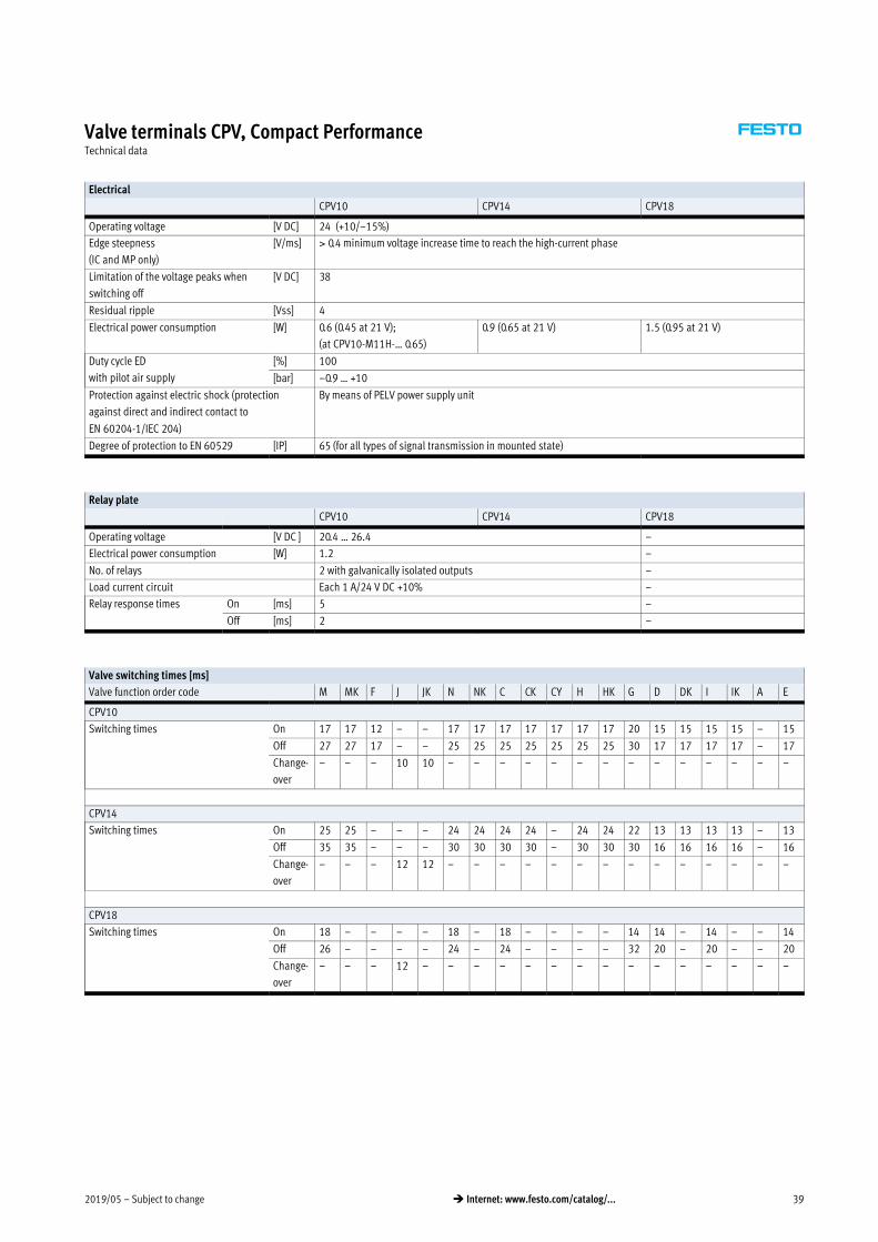
2019/05 – Subject to change 39� Internet: www.festo.com/catalog/...
Valve terminals CPV, Compact PerformanceTechnical data
Electrical
CPV10 CPV14 CPV18
Operating voltage [V DC] 24 (+10/–15%)
Edge steepness
(IC and MP only)
[V/ms] 0.4 minimum voltage increase time to reach the high-current phase
Limitation of the voltage peaks when
switching off
[V DC] 38
Residual ripple [Vss] 4
Electrical power consumption [W] 0.6 (0.45 at 21 V);
(at CPV10-M11H-… 0.65)
0.9 (0.65 at 21 V) 1.5 (0.95 at 21 V)
Duty cycle ED
with pilot air supply
[%] 100
[bar] –0.9 … +10
Protection against electric shock (protection
against direct and indirect contact to
EN 60204-1/IEC 204)
By means of PELV power supply unit
Degree of protection to EN 60529 [IP] 65 (for all types of signal transmission in mounted state)
Relay plate
CPV10 CPV14 CPV18
Operating voltage [V DC ] 20.4 … 26.4 –
Electrical power consumption [W] 1.2 –
No. of relays 2 with galvanically isolated outputs –
Load current circuit Each 1 A/24 V DC +10% –
Relay response times On [ms] 5 –
Off [ms] 2 –
Valve switching times [ms]
Valve function order code M MK F J JK N NK C CK CY H HK G D DK I IK A E
CPV10
Switching times On 17 17 12 – – 17 17 17 17 17 17 17 20 15 15 15 15 – 15
Off 27 27 17 – – 25 25 25 25 25 25 25 30 17 17 17 17 – 17
Change
over
– – – 10 10 – – – – – – – – – – – – – –
CPV14
Switching times On 25 25 – – – 24 24 24 24 – 24 24 22 13 13 13 13 – 13
Off 35 35 – – – 30 30 30 30 – 30 30 30 16 16 16 16 – 16
Change
over
– – – 12 12 – – – – – – – – – – – – – –
CPV18
Switching times On 18 – – – – 18 – 18 – – – – 14 14 – 14 – – 14
Off 26 – – – – 24 – 24 – – – – 32 20 – 20 – – 20
Change
over
– – – 12 – – – – – – – – – – – – – – –

Subject to change – 2019/0540 � Internet: www.festo.com/catalog/...
Valve terminals CPV, Compact PerformanceTechnical data
Materials
CPV10 CPV14 CPV18
Basic electrical unit Die-cast aluminium, PA, NBR
Valve slices Die-cast aluminium
Valve module 5/3G Cast aluminium, POM
Relay plate PA, brass
Blanking plate/separator plate PA
End plates Die-cast aluminium
Flat plate silencer Die-cast aluminium, PE
Pneumatic multiple connector plate Wrought aluminium alloy
Inscription label holder POM, PVC
Seal NBR, HNBR
Product weight
Approx. weight [g] CPV10 CPV14 CPV18
Electrical connection plates with AS-Interface
connection
� on CP valve terminals with 2 valve positions 85 130 275
� on CP valve terminals with 4 valve positions 110 175 355
� on CP valve terminals with 8 valve positions 400 460 –
Electrical connection plates with CP connection
� on CP valve terminals with 4 valve positions 145 230 –
� on CP valve terminals with 6 valve positions 180 250 –
� on CP valve terminals with 8 valve positions 200 300 –
Electrical connection plates with MP connection
� on CP valve terminals with 4 valve positions 110 170 400
� on CP valve terminals with 6 valve positions 140 230 425
� on CP valve terminals with 8 valve positions 165 275 515
End plates (2 pieces) 160 280 740
Pneumatic multiple connector plate
� on CP valve terminals with 2 valve positions 120 270 520
� on CP valve terminals with 4 valve positions 165 390 750
� on CP valve terminals with 6 valve positions 225 510 870
� on CP valve terminals with 8 valve positions 270 630 1300
Flat plate silencer 147 234 –
Relay plate 35 55 –
Blanking plate 25 45 90
Separator plate 25 45 90
Valve sub-bases, vacuum generators 70 110 260
Function element: 5/3G function 46 105 –
Function element: one-way flow control valve 25 54 125

2019/05 – Subject to change 41� Internet: www.festo.com/catalog/...
Valve terminals CPV, Compact PerformanceTechnical data
Vacuum generators
Vacuum as a function of operating pressure
p1 [bar]
p2 [b
ar]
CPV10
p1 [bar]
p2 [b
ar]
CPV14
p1 [bar]
p2 [b
ar]
CPV18
Air consumption as a function of operating pressure Evacuation time for a volume of 1 litre at Pnominal
p [bar]
qn [l
/min
]
CPV18
CPV14
CPV10
p [bar]
t [s]
CPV10
CPV14
CPV18
Suction capacity as a function of partial vacuum at Pnominal
p [bar]
V [l/
min
]
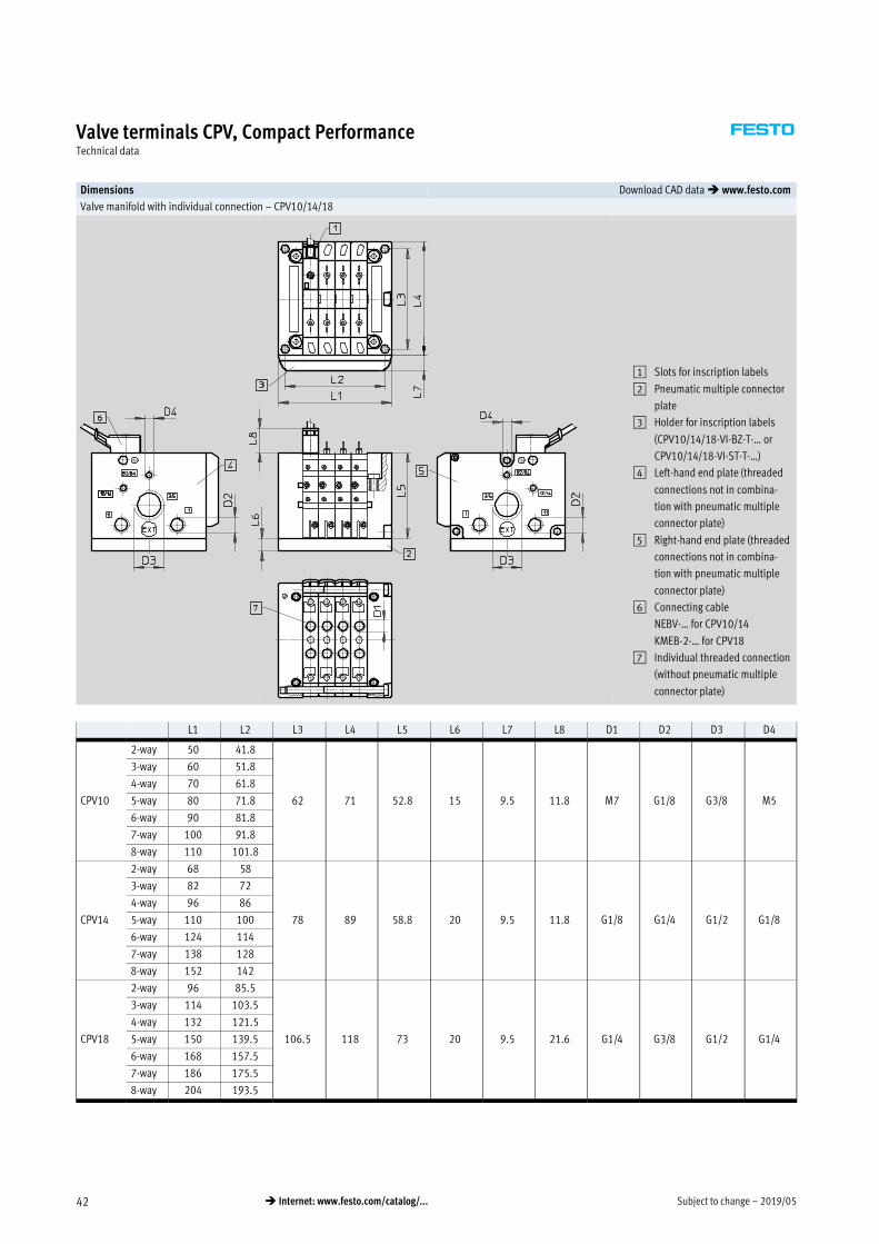
Subject to change – 2019/0542 � Internet: www.festo.com/catalog/...
Valve terminals CPV, Compact PerformanceTechnical data
Dimensions Download CAD data � www.festo.com
Valve manifold with individual connection – CPV10/14/18
1 Slots for inscription labels
2 Pneumatic multiple connector
plate
3 Holder for inscription labels
(CPV10/14/18-VI-BZ-T-… or
CPV10/14/18-VI-ST-T-…)
4 Left-hand end plate (threaded
connections not in combina
tion with pneumatic multiple
connector plate)
5 Right-hand end plate (threaded
connections not in combina
tion with pneumatic multiple
connector plate)
6 Connecting cable
NEBV-… for CPV10/14
KMEB-2-… for CPV18
7 Individual threaded connection
(without pneumatic multiple
connector plate)
L1 L2 L3 L4 L5 L6 L7 L8 D1 D2 D3 D4
CPV10
2-way 50 41.8
62 71 52.8 15 9.5 11.8 M7 G1/8 G3/8 M5
3-way 60 51.8
4-way 70 61.8
5-way 80 71.8
6-way 90 81.8
7-way 100 91.8
8-way 110 101.8
CPV14
2-way 68 58
78 89 58.8 20 9.5 11.8 G1/8 G1/4 G1/2 G1/8
3-way 82 72
4-way 96 86
5-way 110 100
6-way 124 114
7-way 138 128
8-way 152 142
CPV18
2-way 96 85.5
106.5 118 73 20 9.5 21.6 G1/4 G3/8 G1/2 G1/4
3-way 114 103.5
4-way 132 121.5
5-way 150 139.5
6-way 168 157.5
7-way 186 175.5
8-way 204 193.5
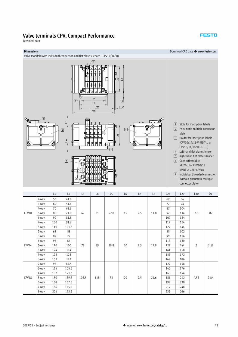
2019/05 – Subject to change 43� Internet: www.festo.com/catalog/...
Valve terminals CPV, Compact PerformanceTechnical data
Dimensions Download CAD data � www.festo.com
Valve manifold with individual connection and flat plate silencer – CPV10/14/18
1 Slots for inscription labels
2 Pneumatic multiple connector
plate
3 Holder for inscription labels
(CPV10/14/18-VI-BZ-T-… or
CPV10/14/18-VI-ST-T-…)
4 Left-hand flat plate silencer
5 Right-hand flat plate silencer
6 Connecting cable
NEBV-… for CPV10/14
KMBE-2-… for CPV18
7 Individual threaded connection
(without pneumatic multiple
connector plate)
L1 L2 L3 L4 L5 L6 L7 L8 L28 L29 L30 D1
CPV10
2-way 50 41.8
62 71 52.8 15 9.5 11.8
67 84
2.5 M7
3-way 60 51.8 77 94
4-way 70 61.8 87 104
5-way 80 71.8 97 114
6-way 90 81.8 107 124
7-way 100 91.8 117 134
8-way 110 101.8 127 144
CPV14
2-way 68 58
78 89 58.8 20 9.5 11.8
85 102
3 G1/8
3-way 82 72 99 116
4-way 96 86 113 130
5-way 110 100 127 144
6-way 124 114 141 158
7-way 138 128 155 172
8-way 152 142 169 186
CPV18
2-way 96 85.5
106.5 118 73 20 9.5 21.6
127 158
4.55 G1/4
3-way 114 105.5 145 176
4-way 132 121.5 163 194
5-way 150 139.5 181 212
6-way 168 157.5 199 230
7-way 186 175.5 217 248
8-way 204 193.5 235 266
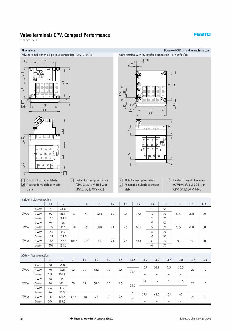
Subject to change – 2019/0544 � Internet: www.festo.com/catalog/...
Valve terminals CPV, Compact PerformanceTechnical data
Dimensions Download CAD data � www.festo.com
Valve terminal with multi-pin plug connection – CPV10/14/18 Valve terminal with AS-Interface connection – CPV10/14/18
1 Slots for inscription labels
2 Pneumatic multiple connector
plate
3 Holder for inscription labels
(CPV10/14/18-VI-BZ-T-… or
CPV10/14/18-VI-ST-T-…)
1 Slots for inscription labels
2 Pneumatic multiple connector
plate
3 Holder for inscription labels
(CPV10/14/18-VI-BZ-T-… or
CPV10/14/18-VI-ST-T-…)
Multi-pin plug connection
L1 L2 L3 L4 L5 L6 L7 L9 L10 L11 L12 L13 L14
CPV10
4-way 70 61.8
62 71 52.8 15 9.5 39.5
10 50
23.5 58.8 306-way 90 81.8 10 70
8-way 110 101.8 20 70
CPV14
4-way 96 86
78 89 58.8 20 9.5 61.8
23 50
23.5 58.8 306-way 124 114 27 70
8-way 152 142 41 70
CPV18
4-way 132 121.5
106.5 118 73 20 9.5 88.4
41 50
28 63 306-way 168 157.5 49 70
8-way 204 193.5 67 70
AS-Interface connection
L1 L2 L3 L4 L5 L6 L7 L12 L15 L16 L17 L18 L19 L20
CPV10
2-way 50 41.8
62 71 52.8 15 9.5
–10.9 38.1 2.5 35.5
21 104-way 70 61.823.5
8-way 110 101.8 – – – –
CPV14
2-way 68 58
78 89 58.8 20 9.5
–14 52 5 35.5
21 104-way 96 8623.5
8-way 152 142 – – – –
CPV18
2-way 96 85.5
106.5 118 73 20 9.5
–27.4 68.2 10.4 40
21 104-way 132 121.528
8-way 204 193.5 – – – –

2019/05 – Subject to change 45� Internet: www.festo.com/catalog/...
Valve terminals CPV, Compact PerformanceTechnical data
Dimensions Download CAD data � www.festo.com
Valve terminal with AS-Interface connection and additional inputs – CPV10/14 Valve terminal with AS-Interface connection and additional inputs – CPV10
1 Slots for inscription labels
2 Pneumatic multiple connector
plate
3 Holder for inscription labels
(CPV10/14/18-VI-BZ-T-… or
CPV10/14/18-VI-ST-T-…)
1 Slots for inscription labels
2 Pneumatic multiple connector
plate
3 Holder for inscription labels
(CPV10/14/18-VI-BZ-T-… or
CPV10/14/18-VI-ST-T-…)
L1 L2 L3 L4 L5 L6 L7 L12 L13 L15 L16 L17
CPV104-way 70 61.8 62 71 52.8 15
9.5 35.1 47.1
10.9 38.1 3
8-way 110 101.8 10.4 38.6 3
CPV14 4-way 96 86 78 89 58.8 20 18.8 46.8 5
L18 L19 L20 L21 L22 L23 L24 L25
CPV104-way
21 10
35 – – – – –
8-way 31.9 88 53.3 20.3 11.5 6.2
CPV14 4-way 43.3 – – – – –
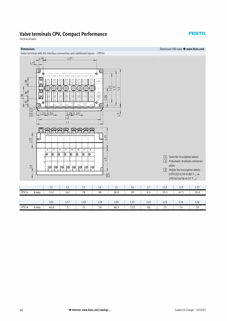
Subject to change – 2019/0546 � Internet: www.festo.com/catalog/...
Valve terminals CPV, Compact PerformanceTechnical data
Dimensions Download CAD data � www.festo.com
Valve terminal with AS-Interface connection and additional inputs – CPV14
1 Slots for inscription labels
2 Pneumatic multiple connector
plate
3 Holder for inscription labels
(CPV10/14/18-VI-BZ-T-… or
CPV10/14/18-VI-ST-T-…)
L1 L2 L3 L4 L5 L6 L7 L12 L13 L15
CPV14 8-way 152 142 78 89 58.8 20 9.5 35.1 47.1 18.8
L16 L17 L18 L19 L20 L21 L22 L23 L24 L26
CPV14 8-way 46.8 5 21 10 46.3 122 66 25 14 18

2019/05 – Subject to change 47� Internet: www.festo.com/catalog/...
Valve terminals CPV, Compact PerformanceTechnical data
Dimensions Download CAD data � www.festo.com
Valve terminal with installation system CPI – CPV10/14 Valve terminal with I-Port interface/IO-Link – CPV10/14
1 Slots for inscription labels
2 Pneumatic multiple connector
plate
3 Holder for inscription labels
(CPV10/14-VI-BZ-T-… or
CPV10/14-VI-ST-T-…)
1 Slots for inscription labels
2 Pneumatic multiple connector
plate
3 Holder for inscription labels
Valve terminal with installation system CPI
L1 L2 L3 L4 L5 L6 L7 L9 L10 L11 L12 L13 L14
CPV10 4-way 70 61.8
62 71 52.8 15 9.5 39.5
13.5 43
23.5 46 306-way 90 81.8 17 56
8-way 110 101.8 27 56
CPV14 4-way 96 86
78 89 58.8 20 9.5 61.8
20
56 23.5 46 306-way 124 114 34
8-way 152 142 48
Valve terminal with I-Port interface/IO-Link
L1 L2 L3 L4 L5 L6 L7 L27 L28 L29 L30
CPV10 8-way 110 101.8 62 71 52.8 15 9.5 26.2 38.3 32 30.2
CPV14 8-way 152 142 78 89 58.8 20 9.5 26.2 38.3 32.4 56.5

Subject to change – 2019/0548 � Internet: www.festo.com/catalog/...
Valve terminals CPV, Compact PerformanceTechnical data
Dimensions Download CAD data � www.festo.com
Valve terminal with Fieldbus Direct – CPV10/14/18
INTERBUS
Valve terminal with Fieldbus Direct – CPV10/14/18
DeviceNet, CANopen, CC-Link
1 Slots for inscription labels
2 Pneumatic multiple connector
plate
3 Holder for inscription labels
(Type CPV10/14/18-VI-BZ-T-… or
CPV10/14/18-VI-ST-T-…)
1 Slots for inscription labels
2 Pneumatic multiple connector
plate
3 Holder for inscription labels
(Type CPV10/14/18-VI-BZ-T-… or
CPV10/14/18-VI-ST-T-…)
L1 L2 L3 L4 L5 L6 L7 L9
CPV10 8-way 110 101.8 62 71 52.8 15
9.5
35.8
CPV14 8-way 152 142 78 89 58.8 20 52.8
CPV18 8-way 204 193.5 106.5 118 73 20 79.8
L10 L11 L12 L13 L14 L27 L31 L32 L33
CPV10 8-way 25
64
26.2 36.7
45
30.9 55.1
60
34.6
CPV14 8-way 46 26.2 36.7 30.9 55.1 34.6
CPV18 8-way 72 31.2 41.7 35.9 59.6 36.6

2019/05 – Subject to change 49� Internet: www.festo.com/catalog/...
Valve terminals CPV, Compact PerformanceTechnical data
Dimensions Download CAD data � www.festo.com
Valve terminal with Fieldbus Direct – CPV10/14/18
Profibus DP including Festo fieldbus, ABB CS31, Moeller Suconet K
1 Slots for inscription labels
2 Pneumatic multiple connector
plate
3 Holder for inscription labels
(CPV10/14/18-VI-BZ-T-… or
CPV10/14/18-VI-ST-T-…)
L1 L2 L3 L4 L5 L6 L7 L9 L10 L12 L13 L32 L33
CPV10 8-way 110 101.8 62 71 52.8 15
9.5
35.5 25 26.2 36.7
60
34.6
CPV14 8-way 152 142 78 89 58.8 20 52.8 46 26.2 36.7 34.6
CPV18 8-way 204 193.5 106.5 118 73 20 79.8 72 31.2 41.7 36.6
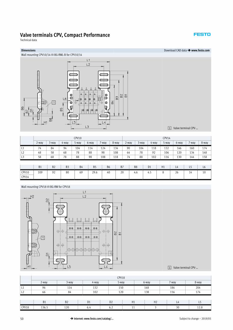
Subject to change – 2019/0550 � Internet: www.festo.com/catalog/...
Valve terminals CPV, Compact PerformanceTechnical data
Dimensions Download CAD data � www.festo.com
Wall mounting CPV10/14-VI-BG-RWL-B for CPV10/14
1 Valve terminal CPV-…
CPV10 CPV14
2-way 3-way 4-way 5-way 6-way 7-way 8-way 2-way 3-way 4-way 5-way 6-way 7-way 8-way
L1 74 84 94 104 114 124 134 90 104 118 132 146 160 174
L2 48 58 68 78 88 98 108 64 78 92 106 120 134 148
L3 58 68 78 88 98 108 118 74 88 102 116 130 144 158
B1 B2 B3 B4 B5 B6 B7 B8 D1 H1 L4 L5 L6
CPV10 109 92 80 69 29.6 40 20 4.6 4.5 8 26 14 10
CPV14
Wall mounting CPV18-VI-BG-RW for CPV18
1 Valve terminal CPV-…
CPV18
2-way 3-way 4-way 5-way 6-way 7-way 8-way
L1 96 114 132 150 168 186 204
L2 66 84 102 120 138 156 174
B1 B2 D1 D2 H1 H2 L4 L5
CPV18 136.5 120 6.4 6.2 11 3 30 12.8

2019/05 – Subject to change 51� Internet: www.festo.com/catalog/...
Valve terminals CPV, Compact PerformanceTechnical data
Dimensions Download CAD data � www.festo.com
Attachment CPV10-VI-BG-ET200X for individual connection and ET200X
B1 B2 B3 B4 D1 D2 D3 H1 L1 L2 L3 L4 L5
CPV10 119.5 109.5 54.8 38.7 6.6 5.4 4 6 152 132 122 101.8 30
Attachment CPV14-VI-BG-ET200X for individual connection and ET200X
B1 B2 B3 B5 D1 D2 D3 H1 L1 L2 L3 L4
CPV14 119.5 109.5 49.1 60.4 6.6 5.4 4 6 152 132 122 142

Subject to change – 2019/0552 � Internet: www.festo.com/catalog/...
Valve terminals CPV, Compact PerformanceTechnical data
Dimensions Download CAD data � www.festo.com
Attachment for H-rail mounting CPV10/14-VI-BG-NRH-35
1 Valve terminal CPV10/14
2 H-rail to EN 60715
B1
±0.1
B2 D1 H1 H2 H3
–0.1
H4
±0.1
L1 L2
±0.1
L3
±0.1
L4
CPV10/14 13 8 M4 10 7.5 7.5 1 49.1 35 27 11.2
Attachment for H-rail mounting CPV18-VI-BG-NRH-35
1 Valve terminal CPV18
2 H-rail to EN 60715
B1 B2 D1 D2 H1 H5 L1 L4 L5 L6 L7 L8 L9
CPV18 20 10 M5 M4 13.1 21 74 11.8 38 31 28.8 29.5 4.6

2019/05 – Subject to change 53� Internet: www.festo.com/catalog/...
Valve terminals CPV, Compact PerformanceTechnical data
Dimensions Download CAD data � www.festo.com
Pneumatic multiple connector plate – CPV10/14/18 Flanged pneumatic multiple connector plate – CPV10/14/18
Multiple connector plate
L1 L2 L3 L4 L5 L6 D1 D2 D3 D4 D5
CPV10
2-way 49.5 42.5 70 63 15 10 M7 G1/8 G1/4 M7 M4
4-way 69.5 62.5
6-way 89.5 82.5
8-way 109.5 102.5
CPV14
2-way 67.5 53.5 86.6 76.6 20 14 G1/8 G1/4 G3/8 G1/8 M4
4-way 95.5 81.5
6-way 123.5 109.5
8-way 151.5 137.5
CPV18
2-way 95.5 87.5 119.6 108 20 18 G1/4 G3/8 G1/2 G1/4 M5
4-way 131 123
6-way 167 159
8-way 203 195
Multiple connector plate with flange
L1 L2 L3 L4 L5 L6 L7 L8 D1 D2 D3 D4 D5
CPV10
2-way 74 62 73 40 15 10 18 6 M7 G1/8 G1/4 M5 6.5
4-way 94 82
6-way 114 102
8-way 134 122
CPV14
2-way 92 80 89 59 20 14 18 6 G1/8 G1/4 G3/8 G1/8 6.5
4-way 120 108
6-way 148 136
8-way 176 164
CPV18
2-way 119 107 118 88 20 18 18 6 G1/4 G3/8 G1/2 G1/4 6.5
4-way 155 143
6-way 191 179
8-way 227 215
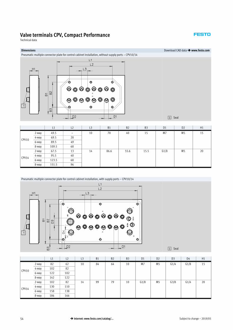
Subject to change – 2019/0554 � Internet: www.festo.com/catalog/...
Valve terminals CPV, Compact PerformanceTechnical data
Dimensions Download CAD data � www.festo.com
Pneumatic multiple connector plate for control cabinet installation, without supply ports – CPV10/14
1 Seal
L1 L2 L3 B1 B2 B3 D1 D2 H1
CPV10
2-way 49.5 – 10 70 40 15 M7 M5 15
4-way 69.5 28
6-way 89.5 49
8-way 109.5 68
CPV14
2-way 67.5 13 14 86.6 55.6 15.5 G1/8 M5 20
4-way 95.5 40
6-way 123.5 68
8-way 151.5 96
Pneumatic multiple connector plate for control cabinet installation, with supply ports – CPV10/14
1 Seal
L1 L2 L3 B1 B2 B3 D1 D2 D3 D4 H1
CPV10
2-way 82 62 10 84 64 10 M7 M5 G1/4 G1/8 15
4-way 102 82
6-way 122 102
8-way 142 122
CPV14
2-way 102 82 14 99 79 10 G1/8 M5 G3/8 G1/4 20
4-way 130 110
6-way 158 138
8-way 186 166

2019/05 – Subject to change 55� Internet: www.festo.com/catalog/...
Valve terminals CPV, Compact PerformanceTechnical data
Dimensions Download CAD data � www.festo.com
Pneumatic multiple connector plate for control cabinet installation, with all ports – CPV10
1 Seal
L1 L2 L3 L4 L5 B1 B2 B3 D1 D2 D3 D4 D5 H1
CPV10
2-way 82 62 – 10 10 84 64 10 G1/8 G1/8 G3/8 M5 M5 18
4-way 102 82 45.55
6-way 122 102 61
8-way 142 122 61

Subject to change – 2019/0556 � Internet: www.festo.com/catalog/...
Valve terminals CPV, Compact PerformanceTechnical data
Dimensions Download CAD data � www.festo.com
Valve kit for 5/3 function – CPV10/14
1 Mounting screw enclosed
separately
Type B1 D1 D2 H1 L1 L2
CPV10-BS-5/3G-M7 9.9 M7 M2.5 22 55.8 23
CPV14-BS-5/3G-x 13.8 G1/8 M3 28 72.8 30
Additional one-way flow control valve function – CPV10/14 Additional one-way flow control valve function for vacuum – CPV10/14
CPV10/14-…-BS-2xGR…-… CPV-…-BS-2xGRZ-V-…
1 Mounting screw enclosed
separately
Type B1 D1 D2 H1 H2 L1 L2 L3
CPV10-BS-2xGR…-M7 9.9 M7 M2.5 26 6 55.8 41.4 22.9
CPV10-BS-2xGRZ-V…-M7 –
CPV14-BS-2xGR…-x 13.8 G1/8 M3 32 8 72.8 53.15 28.65
CPV14-BS-2xGRZ-V…-x –
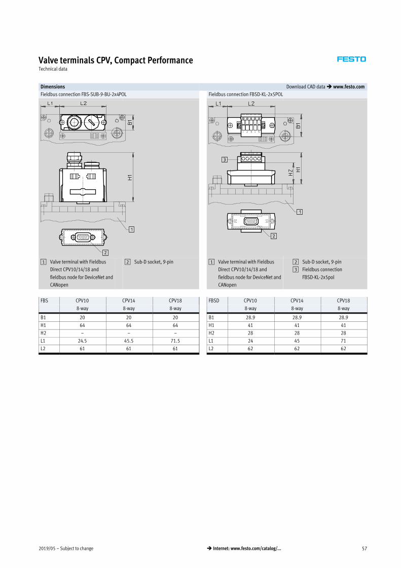
2019/05 – Subject to change 57� Internet: www.festo.com/catalog/...
Valve terminals CPV, Compact PerformanceTechnical data
Dimensions Download CAD data � www.festo.com
Fieldbus connection FBS-SUB-9-BU-2x4POL Fieldbus connection FBSD-KL-2x5POL
1 Valve terminal with Fieldbus
Direct CPV10/14/18 and
fieldbus node for DeviceNet and
CANopen
2 Sub-D socket, 9-pin 1 Valve terminal with Fieldbus
Direct CPV10/14/18 and
fieldbus node for DeviceNet and
CANopen
2 Sub-D socket, 9-pin
3 Fieldbus connection
FBSD-KL-2x5pol
FBS CPV10 CPV14 CPV18 FBSD CPV10 CPV14 CPV18
8-way 8-way 8-way 8-way 8-way 8-way
B1 20 20 20 B1 28.9 28.9 28.9
H1 64 64 64 H1 41 41 41
H2 – – – H2 28 28 28
L1 24.5 45.5 71.5 L1 24 45 71
L2 61 61 61 L2 62 62 62
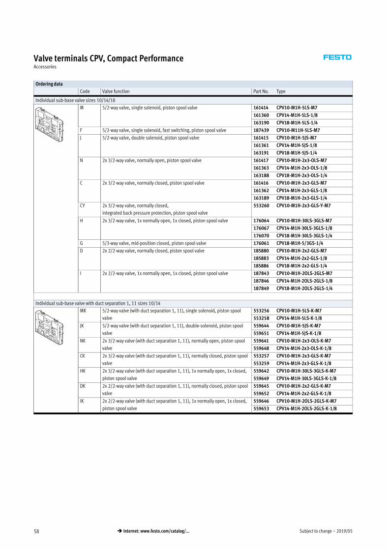
Subject to change – 2019/0558 � Internet: www.festo.com/catalog/...
Valve terminals CPV, Compact PerformanceAccessories
Ordering data
Code Valve function Part No. Type
Individual sub-base valve sizes 10/14/18
M 5/2-way valve, single solenoid, piston spool valve 161414 CPV10-M1H-5LS-M7
161360 CPV14-M1H-5LS-1/8
163190 CPV18-M1H-5LS-1/4
F 5/2-way valve, single solenoid, fast switching, piston spool valve 187439 CPV10-M11H-5LS-M7
J 5/2-way valve, double solenoid, piston spool valve 161415 CPV10-M1H-5JS-M7
161361 CPV14-M1H-5JS-1/8
163191 CPV18-M1H-5JS-1/4
N 2x 3/2-way valve, normally open, piston spool valve 161417 CPV10-M1H-2x3-OLS-M7
161363 CPV14-M1H-2x3-OLS-1/8
163188 CPV18-M1H-2x3-OLS-1/4
C 2x 3/2-way valve, normally closed, piston spool valve 161416 CPV10-M1H-2x3-GLS-M7
161362 CPV14-M1H-2x3-GLS-1/8
163189 CPV18-M1H-2x3-GLS-1/4
CY 2x 3/2-way valve, normally closed,
integrated back pressure protection, piston spool valve
553260 CPV10-M1H-2x3-GLS-Y-M7
H 2x 3/2-way valve, 1x normally open, 1x closed, piston spool valve 176064 CPV10-M1H-30LS-3GLS-M7
176067 CPV14-M1H-30LS-3GLS-1/8
176070 CPV18-M1H-30LS-3GLS-1/4
G 5/3-way valve, mid-position closed, piston spool valve 176061 CPV18-M1H-5/3GS-1/4
D 2x 2/2-way valve, normally closed, piston spool valve 185880 CPV10-M1H-2x2-GLS-M7
185883 CPV14-M1H-2x2-GLS-1/8
185886 CPV18-M1H-2x2-GLS-1/4
I 2x 2/2-way valve, 1x normally open, 1x closed, piston spool valve 187843 CPV10-M1H-2OLS-2GLS-M7
187846 CPV14-M1H-2OLS-2GLS-1/8
187849 CPV18-M1H-2OLS-2GLS-1/4
Individual sub-base valve with duct separation 1, 11 sizes 10/14
MK 5/2-way valve (with duct separation 1, 11), single solenoid, piston spool
valve
553256 CPV10-M1H-5LS-K-M7
553258 CPV14-M1H-5LS-K-1/8
JK 5/2-way valve (with duct separation 1, 11), double-solenoid, piston spool
valve
559644 CPV10-M1H-5JS-K-M7
559651 CPV14-M1H-5JS-K-1/8
NK 2x 3/2-way valve (with duct separation 1, 11), normally open, piston spool
valve
559641 CPV10-M1H-2x3-OLS-K-M7
559648 CPV14-M1H-2x3-OLS-K-1/8
CK 2x 3/2-way valve (with duct separation 1, 11), normally closed, piston spool
valve
553257 CPV10-M1H-2x3-GLS-K-M7
553259 CPV14-M1H-2x3-GLS-K-1/8
HK 2x 3/2-way valve (with duct separation 1, 11), 1x normally open, 1x closed,
piston spool valve
559642 CPV10-M1H-30LS-3GLS-K-M7
559649 CPV14-M1H-30LS-3GLS-K-1/8
DK 2x 2/2-way valve (with duct separation 1, 11), normally closed, piston spool
valve
559645 CPV10-M1H-2x2-GLS-K-M7
559652 CPV14-M1H-2x2-GLS-K-1/8
IK 2x 2/2-way valve (with duct separation 1, 11), 1x normally open, 1x closed,
piston spool valve
559646 CPV10-M1H-2OLS-2GLS-K-M7
559653 CPV14-M1H-2OLS-2GLS-K-1/8

2019/05 – Subject to change 59� Internet: www.festo.com/catalog/...
Valve terminals CPV, Compact PerformanceAccessories
Ordering data
Code Designation Part No. Type
Vacuum generator
A Vacuum generator 185862 CPV10-M1H-V70-M7
185868 CPV14-M1H-V95-1/8
185874 CPV18-M1H-V140-1/4
E Vacuum generator with ejector pulse 185865 CPV10-M1H-VI70-2GLS-M7
185871 CPV14-M1H-VI95-2GLS-1/8
185877 CPV18-M1H-VI140-2GLS-1/4
Function block
G Valve kit for 5/3-way valve function, closed (in combination with valve slice
C) for size 10 and 14
176055 CPV10-BS-5/3G-M7
176057 CPV14-BS-5/3G-1/8
Separator plates
T Separator plate, duct 1/11 closed 161369 CPV10-DZP
162551 CPV14-DZP
163282 CPV18-DZP
S Separator plate, duct 1/11, 3/5 closed 178678 CPV10-DZPR
178680 CPV14-DZPR
184543 CPV18-DZPR
Relay plate
R Relay plate 174478 CPV10-RP2
174480 CPV14-RP2
Blanking plate
L Blanking plate 161368 CPV10-RZP
162550 CPV14-RZP
163283 CPV18-RZP
Additional functions for valve positions
P One-way flow control valve, 2x supply air 184140 CPV10-BS-2XGRZZ-M7
184142 CPV14-BS-2XGRZZ-1/8
Q One-way flow control valve, 2x exhaust air 184141 CPV10-BS-2XGRAZ-M7
184143 CPV14-BS-2XGRAZ-1/8
V One-way flow control valve for vacuum 185889 CPV10-BS-GRZ-V-M7
185891 CPV14-BS-GRZ-V-1/8
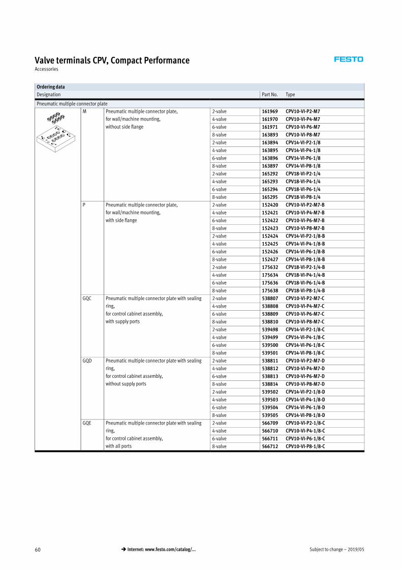
Subject to change – 2019/0560 � Internet: www.festo.com/catalog/...
Valve terminals CPV, Compact PerformanceAccessories
Ordering data
Designation Part No. Type
Pneumatic multiple connector plate
M Pneumatic multiple connector plate,
for wall/machine mounting,
without side flange
2-valve 161969 CPV10-VI-P2-M7
4-valve 161970 CPV10-VI-P4-M7
6-valve 161971 CPV10-VI-P6-M7
8-valve 163893 CPV10-VI-P8-M7
2-valve 163894 CPV14-VI-P2-1/8
4-valve 163895 CPV14-VI-P4-1/8
6-valve 163896 CPV14-VI-P6-1/8
8-valve 163897 CPV14-VI-P8-1/8
2-valve 165292 CPV18-VI-P2-1/4
4-valve 165293 CPV18-VI-P4-1/4
6-valve 165294 CPV18-VI-P6-1/4
8-valve 165295 CPV18-VI-P8-1/4
P Pneumatic multiple connector plate,
for wall/machine mounting,
with side flange
2-valve 152420 CPV10-VI-P2-M7-B
4-valve 152421 CPV10-VI-P4-M7-B
6-valve 152422 CPV10-VI-P6-M7-B
8-valve 152423 CPV10-VI-P8-M7-B
2-valve 152424 CPV14-VI-P2-1/8-B
4-valve 152425 CPV14-VI-P4-1/8-B
6-valve 152426 CPV14-VI-P6-1/8-B
8-valve 152427 CPV14-VI-P8-1/8-B
2-valve 175632 CPV18-VI-P2-1/4-B
4-valve 175634 CPV18-VI-P4-1/4-B
6-valve 175636 CPV18-VI-P6-1/4-B
8-valve 175638 CPV18-VI-P8-1/4-B
GQC Pneumatic multiple connector plate with sealing
ring,
for control cabinet assembly,
with supply ports
2-valve 538807 CPV10-VI-P2-M7-C
4-valve 538808 CPV10-VI-P4-M7-C
6-valve 538809 CPV10-VI-P6-M7-C
8-valve 538810 CPV10-VI-P8-M7-C
2-valve 539498 CPV14-VI-P2-1/8-C
4-valve 539499 CPV14-VI-P4-1/8-C
6-valve 539500 CPV14-VI-P6-1/8-C
8-valve 539501 CPV14-VI-P8-1/8-C
GQD Pneumatic multiple connector plate with sealing
ring,
for control cabinet assembly,
without supply ports
2-valve 538811 CPV10-VI-P2-M7-D
4-valve 538812 CPV10-VI-P4-M7-D
6-valve 538813 CPV10-VI-P6-M7-D
8-valve 538814 CPV10-VI-P8-M7-D
2-valve 539502 CPV14-VI-P2-1/8-D
4-valve 539503 CPV14-VI-P4-1/8-D
6-valve 539504 CPV14-VI-P6-1/8-D
8-valve 539505 CPV14-VI-P8-1/8-D
GQE Pneumatic multiple connector plate with sealing
ring,
for control cabinet assembly,
with all ports
2-valve 566709 CPV10-VI-P2-1/8-C
4-valve 566710 CPV10-VI-P4-1/8-C
6-valve 566711 CPV10-VI-P6-1/8-C
8-valve 566712 CPV10-VI-P8-1/8-C
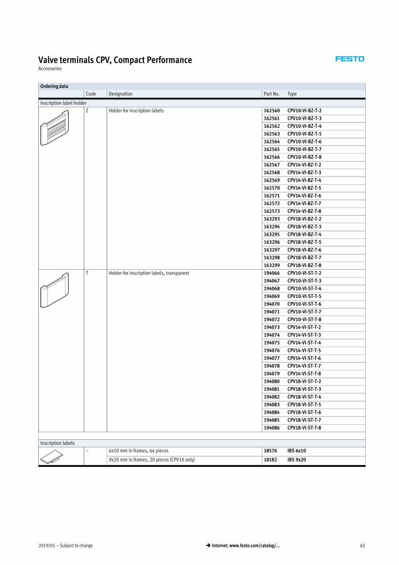
2019/05 – Subject to change 61� Internet: www.festo.com/catalog/...
Valve terminals CPV, Compact PerformanceAccessories
Ordering data
Code Designation Part No. Type
Inscription label holder
Z Holder for inscription labels 162560 CPV10-VI-BZ-T-2
162561 CPV10-VI-BZ-T-3
162562 CPV10-VI-BZ-T-4
162563 CPV10-VI-BZ-T-5
162564 CPV10-VI-BZ-T-6
162565 CPV10-VI-BZ-T-7
162566 CPV10-VI-BZ-T-8
162567 CPV14-VI-BZ-T-2
162568 CPV14-VI-BZ-T-3
162569 CPV14-VI-BZ-T-4
162570 CPV14-VI-BZ-T-5
162571 CPV14-VI-BZ-T-6
162572 CPV14-VI-BZ-T-7
162573 CPV14-VI-BZ-T-8
163293 CPV18-VI-BZ-T-2
163294 CPV18-VI-BZ-T-3
163295 CPV18-VI-BZ-T-4
163296 CPV18-VI-BZ-T-5
163297 CPV18-VI-BZ-T-6
163298 CPV18-VI-BZ-T-7
163299 CPV18-VI-BZ-T-8
T Holder for inscription labels, transparent 194066 CPV10-VI-ST-T-2
194067 CPV10-VI-ST-T-3
194068 CPV10-VI-ST-T-4
194069 CPV10-VI-ST-T-5
194070 CPV10-VI-ST-T-6
194071 CPV10-VI-ST-T-7
194072 CPV10-VI-ST-T-8
194073 CPV14-VI-ST-T-2
194074 CPV14-VI-ST-T-3
194075 CPV14-VI-ST-T-4
194076 CPV14-VI-ST-T-5
194077 CPV14-VI-ST-T-6
194078 CPV14-VI-ST-T-7
194079 CPV14-VI-ST-T-8
194080 CPV18-VI-ST-T-2
194081 CPV18-VI-ST-T-3
194082 CPV18-VI-ST-T-4
194083 CPV18-VI-ST-T-5
194084 CPV18-VI-ST-T-6
194085 CPV18-VI-ST-T-7
194086 CPV18-VI-ST-T-8
Inscription labels
– 6x10 mm in frames, 64 pieces 18576 IBS 6x10
9x20 mm in frames, 20 pieces (CPV18 only) 18182 IBS 9x20
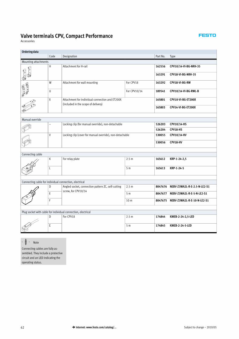
Subject to change – 2019/0562 � Internet: www.festo.com/catalog/...
Valve terminals CPV, Compact PerformanceAccessories
Ordering data
Code Designation Part No. Type
Mounting attachments
H Attachment for H-rail 162556 CPV10/14-VI-BG-NRH-35
163291 CPV18-VI-BG-NRH-35
W Attachment for wall mounting For CPV18 163292 CPV18-VI-BG-RW
U For CPV10/14 189541 CPV10/14-VI-BG-RWL-B
X Attachment for individual connection and ET200X
(included in the scope of delivery)
165801 CPV10-VI-BG-ET200X
165803 CPV14-VI-BG-ET200X
Manual override
– Locking clip (for manual override), non-detachable 526203 CPV10/14-HS
526204 CPV18-HS
V Locking clip (cover for manual override), non-detachable 530055 CPV10/14-HV
530056 CPV18-HV
Connecting cable
K For relay plate 2.5 m 165612 KRP-1-24-2,5
L 5 m 165613 KRP-1-24-5
Connecting cable for individual connection, electrical
D Angled socket, connection pattern ZC, self-cutting
screw, for CPV10/14
2.5 m 8047676 NEBV-Z3WA2L-R-E-2.5-N-LE2-S1
E 5 m 8047677 NEBV-Z3WA2L-R-E-5-N-LE2-S1
F 10 m 8047675 NEBV-Z3WA2L-R-E-10-N-LE2-S1
Plug socket with cable for individual connection, electrical
D For CPV18 2.5 m 174844 KMEB-2-24-2,5-LED
E 5 m 174845 KMEB-2-24-5-LED
-H- Note
Connecting cables are fully as
sembled. They include a protective
circuit and an LED indicating the
operating status.
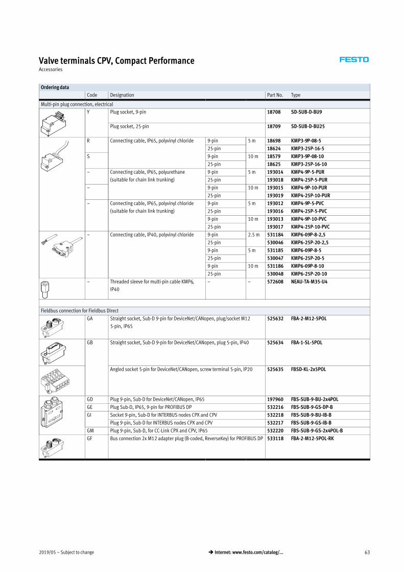
2019/05 – Subject to change 63� Internet: www.festo.com/catalog/...
Valve terminals CPV, Compact PerformanceAccessories
Ordering data
Code Designation Part No. Type
Multi-pin plug connection, electrical
Y Plug socket, 9-pin 18708 SD-SUB-D-BU9
Plug socket, 25-pin 18709 SD-SUB-D-BU25
R Connecting cable, IP65, polyvinyl chloride 9-pin 5 m 18698 KMP3-9P-08-5
25-pin 18624 KMP3-25P-16-5
S 9-pin 10 m 18579 KMP3-9P-08-10
25-pin 18625 KMP3-25P-16-10
– Connecting cable, IP65, polyurethane
(suitable for chain link trunking)
9-pin 5 m 193014 KMP4-9P-5-PUR
25-pin 193018 KMP4-25P-5-PUR
– 9-pin 10 m 193015 KMP4-9P-10-PUR
25-pin 193019 KMP4-25P-10-PUR
– Connecting cable, IP65, polyvinyl chloride
(suitable for chain link trunking)
9-pin 5 m 193012 KMP4-9P-5-PVC
25-pin 193016 KMP4-25P-5-PVC
9-pin 10 m 193013 KMP4-9P-10-PVC
25-pin 193017 KMP4-25P-10-PVC
– Connecting cable, IP40, polyvinyl chloride 9-pin 2.5 m 531184 KMP6-09P-8-2,5
25-pin 530046 KMP6-25P-20-2,5
9-pin 5 m 531185 KMP6-09P-8-5
25-pin 530047 KMP6-25P-20-5
9-pin 10 m 531186 KMP6-09P-8-10
25-pin 530048 KMP6-25P-20-10
– Threaded sleeve for multi-pin cable KMP6,
IP40
– – 572608 NEAU-TA-M35-U4
Fieldbus connection for Fieldbus Direct
GA Straight socket, Sub-D 9-pin for DeviceNet/CANopen, plug/socket M12
5-pin, IP65
525632 FBA-2-M12-5POL
GB Straight socket, Sub-D 9-pin for DeviceNet/CANopen, plug 5-pin, IP40 525634 FBA-1-SL-5POL
Angled socket 5-pin for DeviceNet/CANopen, screw terminal 5-pin, IP20 525635 FBSD-KL-2x5POL
GD Plug 9-pin, Sub-D for DeviceNet/CANopen, IP65 197960 FBS-SUB-9-BU-2x4POL
GE Plug Sub-D, IP65, 9-pin for PROFIBUS DP 532216 FBS-SUB-9-GS-DP-B
GI Socket 9-pin, Sub-D for INTERBUS nodes CPX and CPV 532218 FBS-SUB-9-BU-IB-B
Plug 9-pin, Sub-D for INTERBUS nodes CPX and CPV 532217 FBS-SUB-9-GS-IB-B
GM Plug 9-pin, Sub-D, for CC-Link CPX and CPV, IP65 532220 FBS-SUB-9-GS-2x4POL-B
GF Bus connection 2x M12 adapter plug (B-coded, ReverseKey) for PROFIBUS DP 533118 FBA-2-M12-5POL-RK

Subject to change – 2019/0564 � Internet: www.festo.com/catalog/...
Valve terminals CPV, Compact PerformanceAccessories
Ordering data
Code Designation Part No. Type
Fieldbus connection for Fieldbus Direct
– Socket M12x1, 5-pin, straight,
for self-assembly of a connecting cable for FBA-2-M12-5POL-RK
1067905 NECU-M-B12G5-C2-PB
– Plug M12x1, 5-pin, straight,
for self-assembly of a connecting cable for FBA-2-M12-5POL-RK
1066354 NECU-M-S-B12G5-C2-PB
GL Straight plug, Sub-D 9-pin, screw terminal 5-pin, IP20 197962 FBA-1-KL-5POL
Operating voltage connection for Fieldbus Direct
Straight socket M12, 4-pin, PG7,
IP67
18494 SIE-GD
M12, 4-pin, PG9,
IP67
18495 FBSD-GD-9
Angled socket M12, 4-pin, IP67 12956 SIE-WD-TR
M12, 4-pin, PG9,
IP67
18525 FBSD-WD-9
Blanking plug
Blanking plug 3843 B-M5
174309 B-M7
3568 B-1/8
3569 B-1/4
3570 B-3/8
3571 B-1/2
Push-in fitting
Push-in fitting 153015 QS-1/8-8-I
153018 QS-1/4-10-I
153020 QS-3/8-12-I
153317 QSM-M5-6-I
153321 QSM-M7-6-I
Silencer
Silencer 1205858 AMTE-M-LH-M5
6841 U-1/8-B
6842 U-1/4-B
6843 U-3/8-B
6844 U-1/2-B
161418 UC-M7
Manual
CPV Pneumatics Manual German 165100 P.BE-CPV-DE
English 165200 P.BE-CPV-EN
French 165130 P.BE-CPV-FR
Italian 165160 P.BE-CPV-IT
Spanish 165230 P.BE-CPV-ES
Festo - Your Partner in Automation
www.festo.com
Connect with us
www.festo.com/socialmedia
1 Festo Inc. 2 Festo Pneumatic 3 Festo Corporation 4 Regional Service Center
5300 Explorer DriveMississauga, ON L4W 5G4Canada
Av. Ceylán 3,Col. Tequesquináhuac54020 Tlalnepantla, Estado de México
1377 Motor ParkwaySuite 310Islandia, NY 11749
7777 Columbia RoadMason, OH 45040
Festo Customer Interaction CenterTel: 1 877 463 3786Fax: 1 877 393 3786Email: [email protected]
Multinational Contact Center01 800 337 8669
Festo Customer Interaction Center1 800 993 37861 800 963 3786
Subj
ect t
o ch
ange