Embed Size (px)
Citation preview
94 PCI JOURNAL
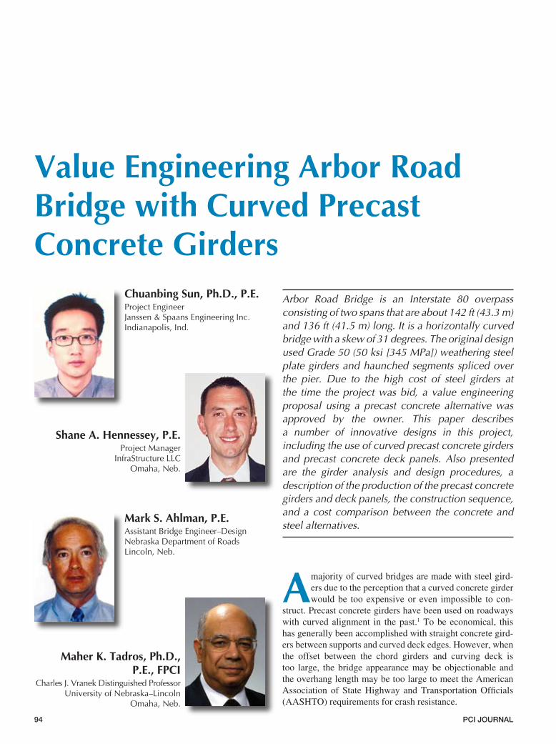
Value Engineering Arbor Road Bridge with Curved Precast Concrete Girders
Chuanbing Sun, Ph.D., P.E.ProjectEngineerJanssen&SpaansEngineeringInc.Indianapolis,Ind.
Shane A. Hennessey, P.E.ProjectManager
InfraStructureLLCOmaha,Neb.
Mark S. Ahlman, P.E.AssistantBridgeEngineer–DesignNebraskaDepartmentofRoadsLincoln,Neb.
Maher K. Tadros, Ph.D., P.E., FPCI
CharlesJ.VranekDistinguishedProfessorUniversityofNebraska–Lincoln
Omaha,Neb.
Arbor Road Bridge is an Interstate 80 overpass consisting of two spans that are about 142 ft (43.3 m) and 136 ft (41.5 m) long. It is a horizontally curved bridge with a skew of 31 degrees. The original design used Grade 50 (50 ksi [345 MPa]) weathering steel plate girders and haunched segments spliced over the pier. Due to the high cost of steel girders at the time the project was bid, a value engineering proposal using a precast concrete alternative was approved by the owner. This paper describes a number of innovative designs in this project, including the use of curved precast concrete girders and precast concrete deck panels. Also presented are the girder analysis and design procedures, a description of the production of the precast concrete girders and deck panels, the construction sequence, and a cost comparison between the concrete and steel alternatives.
A majority of curved bridges are made with steel gird-ers due to the perception that a curved concrete girder would be too expensive or even impossible to con-
struct. Precast concrete girders have been used on roadways with curved alignment in the past.1 To be economical, this has generally been accomplished with straight concrete gird-ers between supports and curved deck edges. However, when the offset between the chord girders and curving deck is too large, the bridge appearance may be objectionable and the overhang length may be too large to meet the American Association of State Highway and Transportation Officials (AASHTO) requirements for crash resistance.
March–April 2007 9�
To overcome these disadvantages, a “curved” concrete girder can be made with straight 40-ft-long (12.2-m) seg-ments that have a “kink” between the adjacent segments. Due to standard casting bed lengths, a 40 ft (12.2 m) length is typical for precast concrete I-girders and other products. Thus, the available stock of forms used for straight pretensioned concrete I- and box girders can be used with slight, inexpensive modifications to cre-ate girders that have the appearance and function of curved girders. It was also possible to replace the high-
performance steel plate girder design with a concrete girder design without increasing the superstructure depth.
This concept was the basis for the value engineering effort for the Arbor Road Bridge in Lincoln, Neb. The girders used on this bridge were origi-nally conceived as NU1100 (43 in. [1100 mm] deep) I-girders (NU des-ignates Nebraska University design). However, due to the special circum-stances of this bridge and the contrac-tor’s uncertainty of whether both pre-casting companies in Nebraska (which own NU I-girder forms) would bid on
the project, the contractor decided to use a generic U-shaped girder. In this paper, the authors present the details of the first implementation of the curved concrete girder bridge in Nebraska.
ORIGINAL DESIGN USING STEEL GIRDERS
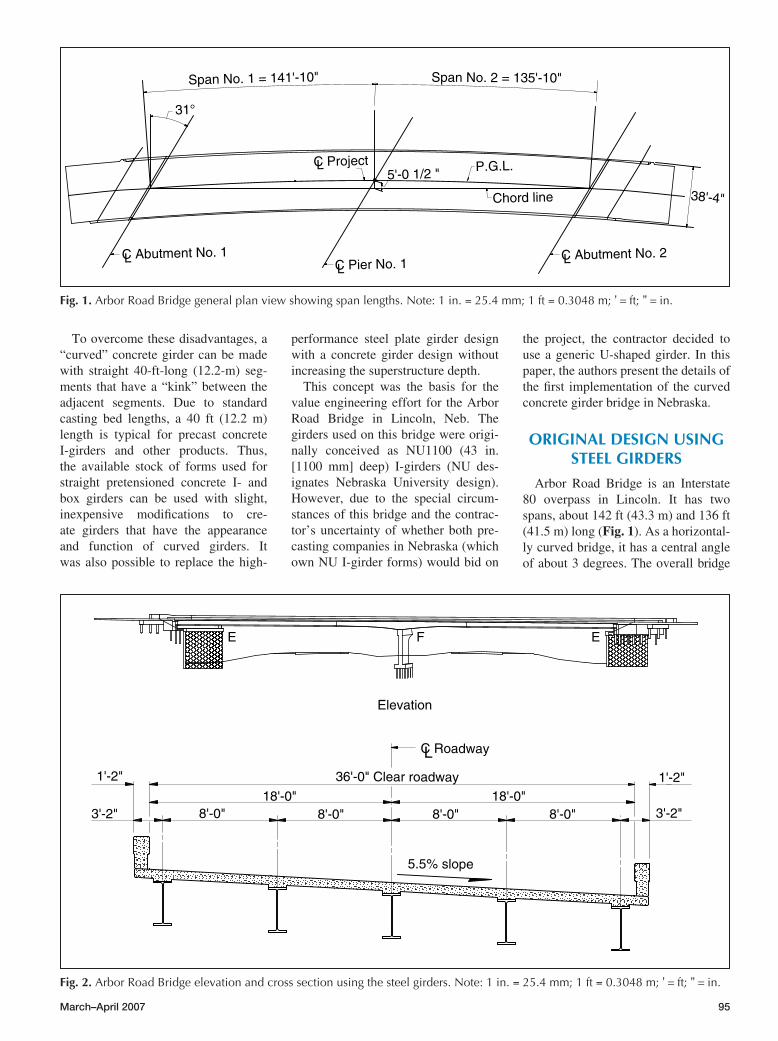
Arbor Road Bridge is an Interstate 80 overpass in Lincoln. It has two spans, about 142 ft (43.3 m) and 136 ft (41.5 m) long (Fig. 1). As a horizontal-ly curved bridge, it has a central angle of about 3 degrees. The overall bridge
Fig. 1.ArborRoadBridgegeneralplanviewshowingspanlengths.Note:1in.=25.4mm;1ft=0.3048m;'=ft;'' =in.
Span No. 1 = 141'-10"
LC Abutment No. 1
31°
L
LLC Pier No. 1
Span No. 2 = 135'-10"
C Abutment No. 2
38'-4"Chord line
5'-0 1/2 "C Project P.G.L.
Fig. 2.ArborRoadBridgeelevationandcrosssectionusingthesteelgirders.Note:1in.=25.4mm;1ft=0.3048m;'=ft;'' =in.
FE E
Elevation
1'-2"1'-2"
C Roadway
18'-0"8'-0"
36'-0" Clear roadway
3'-2"
5.5% slope
8'-0" 8'-0" 8'-0" 3'-2"18'-0"
L
96 PCI JOURNAL
width is 38.33 ft (11.7 m), and it has a skew of 31 degrees. The original design used steel plate I-girders with a 7.5-in.-thick (191 mm) cast-in-place (CIP) concrete deck slab. Grade 50 (50 ksi [345 MPa]) weathering steel plate was specified for the plate girder to allow a girder depth of 43.5 in. (1105 mm), in-creasing to 67.5 in. (1715 mm) at the pier, to span the 142 ft (43.3 m) length.
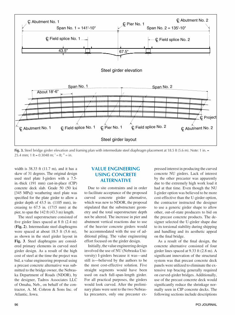
The steel superstructure consisted of five girder lines spaced at 8 ft (2.4 m) (Fig. 2). Intermediate steel diaphragms were spaced at about 18.5 ft (5.6 m), as shown in the steel girder layout in Fig. 3. Steel diaphragms are consid-ered primary elements in curved steel girder design. As a result of the high cost of steel at the time the project was bid, a value engineering proposal using a precast concrete alternative was sub-mitted to the bridge owner, the Nebras-ka Department of Roads (NDOR), by the designer, Tadros Associates LLC of Omaha, Neb., on behalf of the con-tractor, A. M. Cohron & Sons Inc. of Atlantic, Iowa.
VALUE ENGINEERING USING CONCRETE
ALTERNATIVE
Due to site constraints and in order to facilitate acceptance of the proposed curved concrete girder alternative, which was new to NDOR, the proposal stipulated that the substructure geom-etry and the total superstructure depth not be altered. The increase in pier and abutment vertical reactions due to use of the heavier concrete girders would be accommodated with the use of ad-ditional piling. The value engineering effort focused on the girder design.
Initially, the value engineering design involved the use of NU (Nebraska Uni-versity) I-girders because it was—and still is—believed by the authors to be the most cost-effective solution. Five straight segments would have been used on each full-span-length girder. For all practical purposes, the girders would look curved. After the prelimi-nary plans were sent to the two Nebras-ka precasters, only one precaster ex-
pressed interest in producing the curved concrete NU girders. Lack of interest by the other precaster was apparently due to the extremely high work load it had at that time. Even though the NU I-girder option was believed to be more cost-effective than the U-girder option, the contractor instructed the designer to use a generic girder shape to allow other, out-of-state producers to bid on the precast concrete products. The de-signer selected the U-girder shape due to its torsional stability during shipping and handling and its aesthetic appeal on the final bridge.
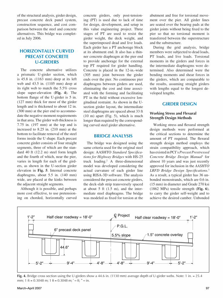
As a result of the final design, the concrete alternative consisted of four girder lines spaced at 9.33 ft (2.8 m). A significant innovation of the structural system was that precast concrete deck panels were utilized to eliminate the ex-tensive top bracing generally required on curved-girder bridges. Additionally, use of the precast concrete deck would significantly reduce the shrinkage nor-mally seen in CIP concrete decks. The following sections include descriptions
Fig. 3.Steelbridgegirderelevationandframingplanwithintermediatesteeldiaphragmplacementat18.5ft(5.6m).Note:1in.=25.4mm;1ft=0.3048m;'=ft;'' =in.
Span No. 2 = 135'-10"Span No. 1 = 141'-10"
C Abutment No. 1L
LC Field splice No. 1
LC Pier No. 1
C Field splice No. 2L
LC Abutment No. 2
43.5" 67.5"
C Project
C Field splice No. 1 C Field splice No. 2C Pier No. 1
Span No. 1 Span No. 2
C Abutment No. 2C Abutment No. 1L L L L L
L
About 18'-6"
Steel girder elevation
Steel girder layout
March–April 2007 97
of the structural analysis, girder design, precast concrete deck panel system, construction sequence, and cost com-parison between the steel and concrete alternatives. This bridge was complet-ed in July 2006.
HORIZONTALLY CURVED PRECAST CONCRETE
U-GIRDERS
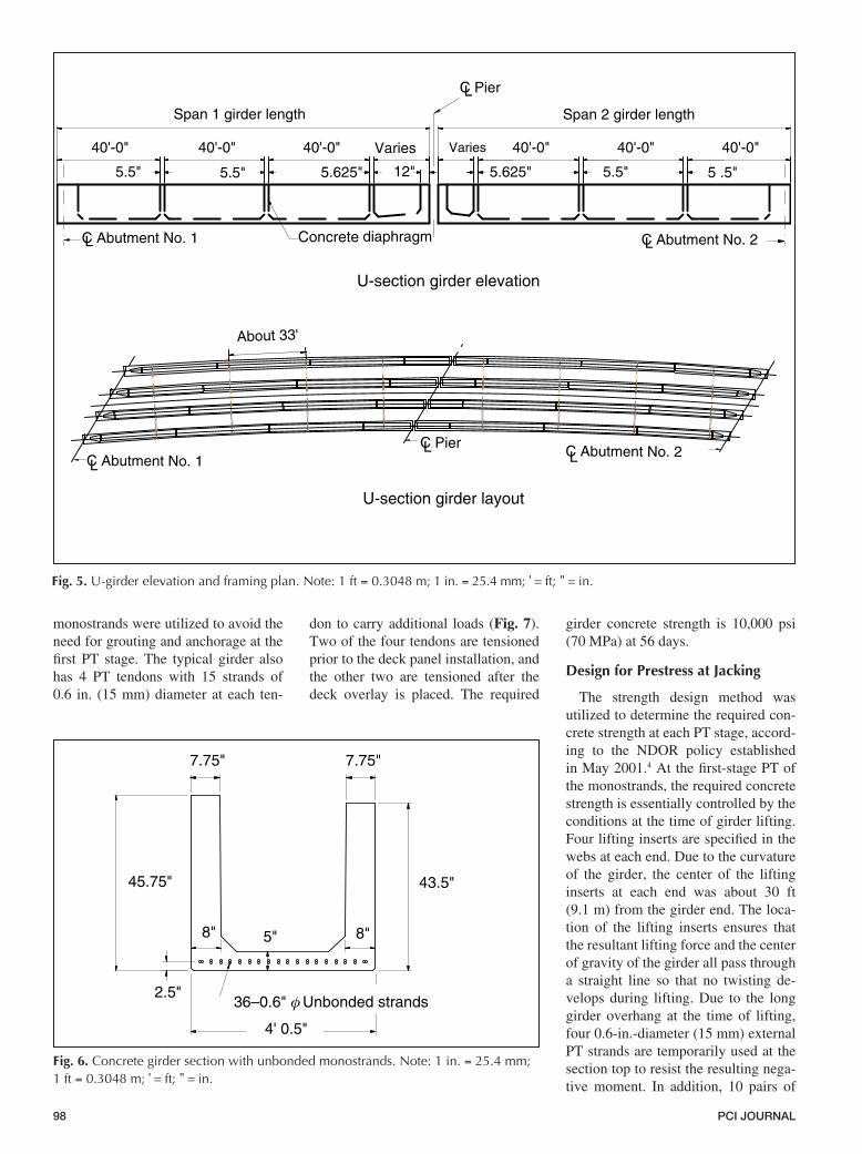
The concrete alternative utilizes a prismatic U-girder section, which is 45.8 in. (1163 mm) deep at its left web and 43.5 in. (1105 mm) deep at its right web to match the 5.5% cross slope super-elevation (Fig. 4). The bottom flange of the U-girder is 5 in. (127 mm) thick for most of the girder length and is thickened to about 12 in. (300 mm) at the pier end to accommo-date the negative moment requirements in that area. The girder web thickness is 7.75 in. (197 mm) at the top and is increased to 8.25 in. (210 mm) at the bottom to facilitate removal of the steel forms inside the U shape. Each precast concrete girder consists of four straight segments, three of which are the stan-dard 40 ft (12.2 m) steel form length and the fourth of which, near the pier, varies in length for each of the gird-ers, as shown in the U-section girder elevation in Fig. 5. Internal concrete diaphragms, about 5.5 in. (140 mm) wide, are placed at the kinks between the adjacent straight segments.
Although it is possible, and perhaps more cost effective, to use pretension-ing on chorded, horizontally curved
concrete girders, only post-tension-ing (PT) is used due to lack of time for design, development, and setup in this value engineering project. Three stages of PT are used to resist the girder weight, the deck weight, and the superimposed dead and live loads. Each girder has a PT anchorage block at its abutment end. It also has a thin-ner concrete diaphragm at the pier end to provide anchorage for the external top PT required for girder handling. Concrete is placed in the 12-in.-wide (305 mm) joint between the girder ends over the pier. No continuous pier diaphragms between girders are used, eliminating the cost and time associ-ated with the forming and facilitating PT in the field without excessive lon-gitudinal restraint. As shown in the U-section girder layout, the intermediate steel diaphragms are spaced about 33 ft (10 m) apart (Fig. 5), which is much longer than required by the correspond-ing curved steel girder alternative.
BRIDGE ANALYSIS
The bridge was designed using the same criteria used for the original steel design: AASHTO Standard Specifica-tions for Highway Bridges with HS-25 truck loading.2 A three-dimensional model was developed considering the actual curvature of each girder line using RISA-3D software. The analysis considered the precast concrete girders, the deck-slab strip transversely spaced at about 5 ft (1.5 m), and the inter-mediate steel diaphragms. The bridge was modeled as fixed for torsion at the
abutment and free for torsional move-ment over the pier. All girder lines are seated over the bearing pads at the girder joints without being fixed to the pier so that no torsional moment is transferred between the superstructure and the substructure.
During the grid analysis, bridge members were subjected to dead loads, PT loads, and live loads. Torsional moments in the girders and forces in the intermediate diaphragms were de-termined. Also determined were the bending moments and shear forces in the girders, which are comparable to the results, assuming straight girders with lengths equal to the longest de-veloped lengths.
GIRDER DESIGN
Working Stress and Flexural Strength Design Methods
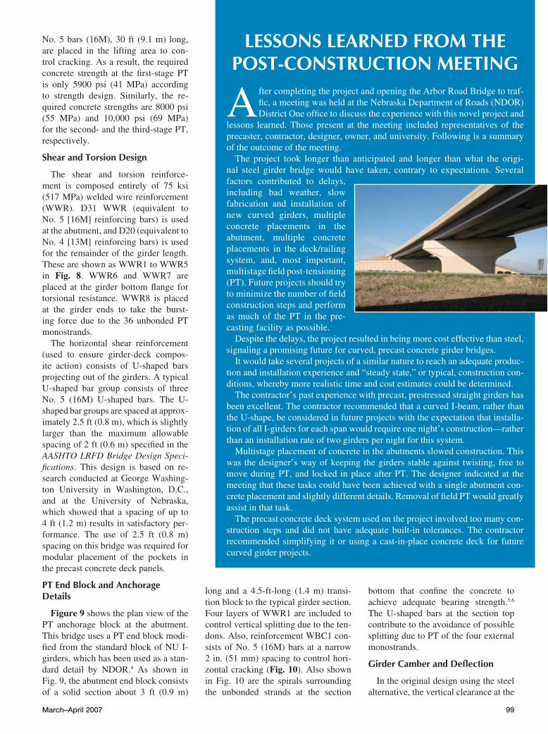
Working stress and flexural strength design methods were performed at the critical sections to determine the amount of PT required. The flexural strength design method employs the strain compatibility approach, which has existed in PCI’s Precast Prestressed Concrete Bridge Design Manual1 for almost 10 years and was just recently approved for inclusion in the AASHTO LRFD Bridge Design Specifications.3 As a result, a typical girder has 36 un-bonded monostrands, which are 0.6 in. (15 mm) in diameter and Grade 270 ksi (1862 MPa) tensile strength (Fig. 6), to carry the girder self-weight and to achieve the desired camber. Unbonded
Fig. 4.BridgecrosssectionusingtheU-girdersshowa44.6in.(1130mm)averagedepthofU-girderwebs.Note:1in.=25.4mm;1ft=0.3048m;1ft=0.3048m;'=ft;'' =in.
Half clear roadway = 18'-0" 1'-2"
P.G.L.
5.5% slope
C Project Half clear roadway = 18'-0" 1'-2"
1.5" concrete overlay6" precast deck panel
L
9'-4"5'-2" 5'-2"4'-8"4'-8" 9'-4"
44.6"
98 PCI JOURNAL
monostrands were utilized to avoid the need for grouting and anchorage at the first PT stage. The typical girder also has 4 PT tendons with 15 strands of 0.6 in. (15 mm) diameter at each ten-
don to carry additional loads (Fig. 7). Two of the four tendons are tensioned prior to the deck panel installation, and the other two are tensioned after the deck overlay is placed. The required
girder concrete strength is 10,000 psi (70 MPa) at 56 days.
Design for Prestress at Jacking
The strength design method was utilized to determine the required con-crete strength at each PT stage, accord-ing to the NDOR policy established in May 2001.4 At the first-stage PT of the monostrands, the required concrete strength is essentially controlled by the conditions at the time of girder lifting. Four lifting inserts are specified in the webs at each end. Due to the curvature of the girder, the center of the lifting inserts at each end was about 30 ft (9.1 m) from the girder end. The loca-tion of the lifting inserts ensures that the resultant lifting force and the center of gravity of the girder all pass through a straight line so that no twisting de-velops during lifting. Due to the long girder overhang at the time of lifting, four 0.6-in.-diameter (15 mm) external PT strands are temporarily used at the section top to resist the resulting nega-tive moment. In addition, 10 pairs of
Fig. 5.U-girderelevationandframingplan.Note:1ft=0.3048m;1in.=25.4mm;'=ft;'' =in.
Span 2 girder length
5 .5"
Span 1 girder length
40'-0"
5.5" 12"5.625"5.5" 5.5"5.625"
40'-0" 40'-0" 40'-0" 40'-0" 40'-0"Varies
C Abutment No. 1 ConcreteL C Abutment No. 2Ldiaphragm
C PierL
Varies
C Abutment No. 1C Abutment No. 2
C PierL
LL
About 33'
U-section girder elevation
U-section girder layout
Fig. 6.Concretegirdersectionwithunbondedmonostrands.Note:1in.=25.4mm;1ft=0.3048m;'=ft;'' =in.
4' 0.5"
45.75"
5"
2.5"
7.75"
43.5"
8" 8"
36–0.6" Unbonded strands
7.75"
March–April 2007 99
No. 5 bars (16M), 30 ft (9.1 m) long, are placed in the lifting area to con-trol cracking. As a result, the required concrete strength at the first-stage PT is only 5900 psi (41 MPa) according to strength design. Similarly, the re-quired concrete strengths are 8000 psi (55 MPa) and 10,000 psi (69 MPa) for the second- and the third-stage PT, respectively.
Shear and Torsion Design
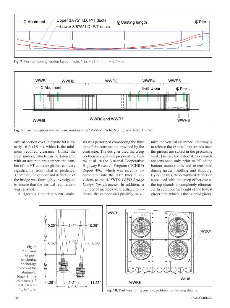
The shear and torsion reinforce-ment is composed entirely of 75 ksi (517 MPa) welded wire reinforcement (WWR). D31 WWR (equivalent to No. 5 [16M] reinforcing bars) is used at the abutment, and D20 (equivalent to No. 4 [13M] reinforcing bars) is used for the remainder of the girder length. These are shown as WWR1 to WWR5 in Fig. 8. WWR6 and WWR7 are placed at the girder bottom flange for torsional resistance. WWR8 is placed at the girder ends to take the burst-ing force due to the 36 unbonded PT monostrands.
The horizontal shear reinforcement (used to ensure girder-deck compos-ite action) consists of U-shaped bars projecting out of the girders. A typical U-shaped bar group consists of three No. 5 (16M) U-shaped bars. The U-shaped bar groups are spaced at approx-imately 2.5 ft (0.8 m), which is slightly larger than the maximum allowable spacing of 2 ft (0.6 m) specified in the AASHTO LRFD Bridge Design Speci-fications. This design is based on re-search conducted at George Washing-ton University in Washington, D.C., and at the University of Nebraska, which showed that a spacing of up to 4 ft (1.2 m) results in satisfactory per-formance. The use of 2.5 ft (0.8 m) spacing on this bridge was required for modular placement of the pockets in the precast concrete deck panels.
PT End Block and Anchorage Details
Figure 9 shows the plan view of the PT anchorage block at the abutment. This bridge uses a PT end block modi-fied from the standard block of NU I-girders, which has been used as a stan-dard detail by NDOR.4 As shown in Fig. 9, the abutment end block consists of a solid section about 3 ft (0.9 m)
long and a 4.5-ft-long (1.4 m) transi-tion block to the typical girder section. Four layers of WWR1 are included to control vertical splitting due to the ten-dons. Also, reinforcement WBC1 con-sists of No. 5 (16M) bars at a narrow 2 in. (51 mm) spacing to control hori-zontal cracking (Fig. 10). Also shown in Fig. 10 are the spirals surrounding the unbonded strands at the section
bottom that confine the concrete to achieve adequate bearing strength.5,6 The U-shaped bars at the section top contribute to the avoidance of possible splitting due to PT of the four external monostrands.
Girder Camber and Deflection
In the original design using the steel alternative, the vertical clearance at the
LESSONS LEARNED FROM THE POST-CONSTRUCTION MEETING
After completing the project and opening the Arbor Road Bridge to traf-fic, a meeting was held at the Nebraska Department of Roads (NDOR) District One office to discuss the experience with this novel project and
lessons learned. Those present at the meeting included representatives of the precaster, contractor, designer, owner, and university. Following is a summary of the outcome of the meeting.
The project took longer than anticipated and longer than what the origi-nal steel girder bridge would have taken, contrary to expectations. Several factors contributed to delays, including bad weather, slow fabrication and installation of new curved girders, multiple concrete placements in the abutment, multiple concrete placements in the deck/railing system, and, most important, multistage field post-tensioning (PT). Future projects should try to minimize the number of field construction steps and perform as much of the PT in the pre-casting facility as possible.
Despite the delays, the project resulted in being more cost effective than steel, signaling a promising future for curved, precast concrete girder bridges.
It would take several projects of a similar nature to reach an adequate produc-tion and installation experience and “steady state,” or typical, construction con-ditions, whereby more realistic time and cost estimates could be determined.
The contractor’s past experience with precast, prestressed straight girders has been excellent. The contractor recommended that a curved I-beam, rather than the U-shape, be considered in future projects with the expectation that installa-tion of all I-girders for each span would require one night’s construction—rather than an installation rate of two girders per night for this system.
Multistage placement of concrete in the abutments slowed construction. This was the designer’s way of keeping the girders stable against twisting, free to move during PT, and locked in place after PT. The designer indicated at the meeting that these tasks could have been achieved with a single abutment con-crete placement and slightly different details. Removal of field PT would greatly assist in that task.
The precast concrete deck system used on the project involved too many con-struction steps and did not have adequate built-in tolerances. The contractor recommended simplifying it or using a cast-in-place concrete deck for future curved girder projects.
100 PCI JOURNAL
critical section over Interstate 80 is ex-actly 16 ft (4.9 m), which is the mini-mum required clearance. Unlike the steel girders, which can be fabricated with an accurate pre-camber, the cam-ber of the PT concrete girders can vary significantly from what is predicted. Therefore, the camber and deflection of the bridge was thoroughly investigated to ensure that the vertical requirement was satisfied.
A rigorous time-dependent analy-
sis was performed considering the time line of the construction provided by the contractor. The designer used the creep coefficient equations proposed by Tad-ros et al. in the National Cooperative Highway Research Program (NCHRP) Report 496,7 which was recently in-corporated into the 2005 Interim Re-visions to the AASHTO LRFD Bridge Design Specifications. In addition, a number of methods were utilized to in-crease the camber and possibly maxi-
mize the vertical clearance. One way is to release the external top strands once the girders are stored in the precasting yard. That is, the external top strands are tensioned only prior to PT of the bottom monostrands and re-tensioned during girder handling and shipping. By doing this, the downward deflection associated with the creep effect due to the top strands is completely eliminat-ed. In addition, the height of the lowest girder line, which is the exterior girder,
Fig. 7. Post-tensioningtendonlayout.Note:1in.=25.4mm;'=ft,'' =in.
C Abutment Upper 3.875" I.D. P/T ducts
Lower 3.875" I.D. P/T ductsL C PierLC Casting lengthL
Fig. 8.Concretegirderweldedwirereinforcement(WWR).Note:No.5bar=16M;#=No.
WWR8
WWR1 WWR2 WWR3 WWR4
LC Abutment LC Pier
WWR6 and WWR7 WWR8
WWR5
3-#5 U-bar
Fig. 9.Planview
ofpost-tensioninganchorage
blockattheabutment.
Note:1in.=25.4mm;1ft=0.3048m;'=ft;'' =in.
DYWIDAGMA 68 19
DYWIDAG
MA 68 19
3'-0
"4'
-6"
6"
10.25" 2'-4" 10.25"
1'-6.25" 1'-0" 1'-6.25"
11.25" 2'-2" 11.25"4'-0.5"
Fig. 10.Post-tensioninganchorageblockreinforcingdetails.
WWR1
WBC1
WWR8Spiral
March–April 2007 101
was reduced 4 in. (102 mm) to ensure that the minimum vertical clearance re-quirement was met.
Internal Concrete Diaphragm
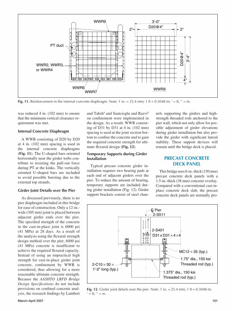
A WWR consisting of D20 by D20 at 4 in. (102 mm) spacing is used in the internal concrete diaphragms (Fig. 11). The U-shaped bars oriented horizontally near the girder webs con-tribute to resisting the pull-out force during PT at the kinks. The vertically oriented U-shaped bars are included to avoid possible bursting due to the external top strands.
Girder Joint Details over the Pier
As discussed previously, there is no pier diaphragm included in this bridge for ease of construction. Only a 12-in.-wide (305 mm) joint is placed between adjacent girder ends over the pier. The specified strength of the concrete in the cast-in-place joint is 6000 psi (41 MPa) at 28 days. As a result of the analysis using the flexural strength design method over the pier, 6000 psi (41 MPa) concrete is insufficient to achieve the required flexural capacity. Instead of using an impractical high strength for cast-in-place girder joint concrete, confinement by WWR is considered, thus allowing for a more reasonable ultimate concrete strength. Because the AASHTO LRFD Bridge Design Specifications do not include provisions on confined concrete anal-ysis, the research findings by Lambert
and Tabsh8 and Saatcioglu and Razvi9 on confinement were implemented in the design. As a result, WWR consist-ing of D31 by D31 at 4 in. (102 mm) spacing is used at the joint section bot-tom to confine the concrete and to gain the required concrete strength for ulti-mate flexural design (Fig. 12).
Temporary Supports during Girder Installation
Typical precast concrete girder in-stallation requires two bearing pads at each end of adjacent girders over the pier. To reduce the amount of bearing, temporary supports are included dur-ing girder installation (Fig. 12). Girder support brackets consist of steel chan-
nels supporting the girders and high-strength threaded rods anchored to the pier wall, which not only allow for pos-sible adjustment of girder elevations during girder installation but also pro-vide the girder with significant lateral stability. These support devices will remain until the bridge deck is placed.
PRECAST CONCRETE DECK PANEL
This bridge uses 6-in.-thick (150 mm) precast concrete deck panels with a 1.5-in.-thick (38 mm) concrete overlay. Compared with a conventional cast-in-place concrete deck slab, the precast concrete deck panels are normally pro-
Fig. 12.Girderjointdetailsoverthepier.Note:1in.=25.4mm;1ft=0.3048m;'=ft;''=in.
MC12 × 35 (typ.)
2-C10 × 30 ×1'-2" long (typ.)
1.75" dia., 150 ksiThreaded rod (typ.)
1.375" dia., 150 ksiThreaded rod (typ.)
D31 x D31 × 4 × 4
2-S511
2-S401
C PierL
Fig. 11.Reinforcementintheinternalconcretediaphragm.Note:1in.=25.4mm;1ft=0.3048m;'=ft;''=in.
WWR9
WWR2, WWR3,or WWR4
WWR6WWR7
PT duct
D20@4"2"
3'-0"
2"
D20
@4"
3'-4
"
4"
WWR9
102 PCI JOURNAL
duced with better quality control. Also, the majority of shrinkage, temperature drop due to the cement hydration cycle, and creep has occurred before the pre-cast concrete panels are made com-posite with the girders. In addition, the deck is PT with the girders in the third stage. Therefore, the precast concrete deck panels are expected to last as long
as the precast concrete girders. Another possible benefit of using precast con-crete panels is fast construction.
The primary reason for using the pre-cast concrete panels in curved bridge construction, however, is to eliminate the extensive lateral top bracing most-ly required to prevent twisting of the girders during deck placement. In this
bridge, the original steel girder design did not provide any additional top lat-eral bracing due to the small bridge curvature, but intermediate steel dia-phragms were provided at a relatively close spacing of about 18.5 ft (5.6 m). Use of the precast concrete deck panel systems allows an increase in the steel diaphragm spacing to about 33 ft (10 m).
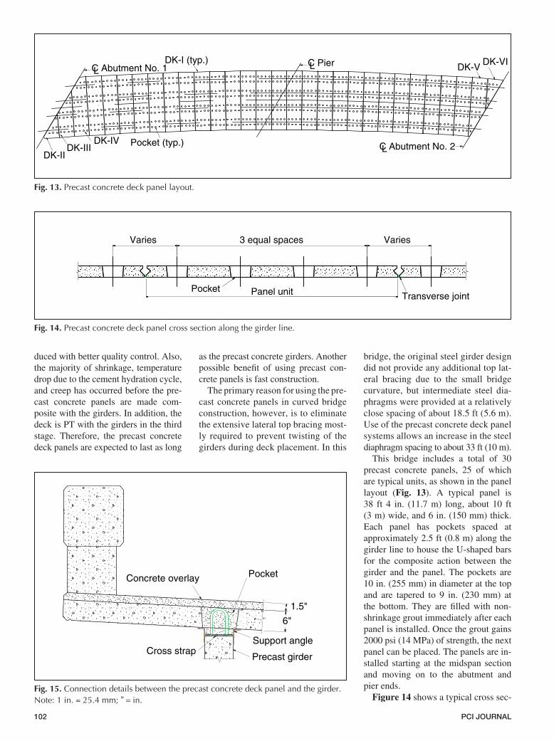
This bridge includes a total of 30 precast concrete panels, 25 of which are typical units, as shown in the panel layout (Fig. 13). A typical panel is 38 ft 4 in. (11.7 m) long, about 10 ft (3 m) wide, and 6 in. (150 mm) thick. Each panel has pockets spaced at approximately 2.5 ft (0.8 m) along the girder line to house the U-shaped bars for the composite action between the girder and the panel. The pockets are 10 in. (255 mm) in diameter at the top and are tapered to 9 in. (230 mm) at the bottom. They are filled with non-shrinkage grout immediately after each panel is installed. Once the grout gains 2000 psi (14 MPa) of strength, the next panel can be placed. The panels are in-stalled starting at the midspan section and moving on to the abutment and pier ends.
Figure 14 shows a typical cross sec-
Fig. 13.Precastconcretedeckpanellayout.
LC Abutment No. 1
C Abutment No. 2
C PierL
LPocket (typ.)
DK-I (typ.)
DK-II
DK-IVDK-III
DK-VIDK-V
Fig. 14.Precastconcretedeckpanelcrosssectionalongthegirderline.
Panel unit
3 equal spacesVaries Varies
PocketTransverse joint
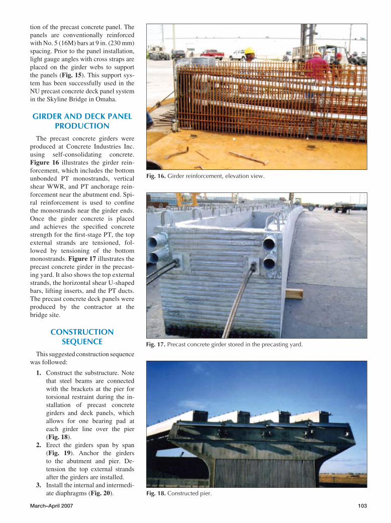
Fig. 15.Connectiondetailsbetweentheprecastconcretedeckpanelandthegirder.Note:1in.=25.4mm;'' =in.
Concrete overlay Pocket
6"
1.5"
Cross strapPrecast girder
Support angle
March–April 2007 103
tion of the precast concrete panel. The panels are conventionally reinforced with No. 5 (16M) bars at 9 in. (230 mm) spacing. Prior to the panel installation, light gauge angles with cross straps are placed on the girder webs to support the panels (Fig. 15). This support sys-tem has been successfully used in the NU precast concrete deck panel system in the Skyline Bridge in Omaha.
GIRDER AND DECK PANEL PRODUCTION
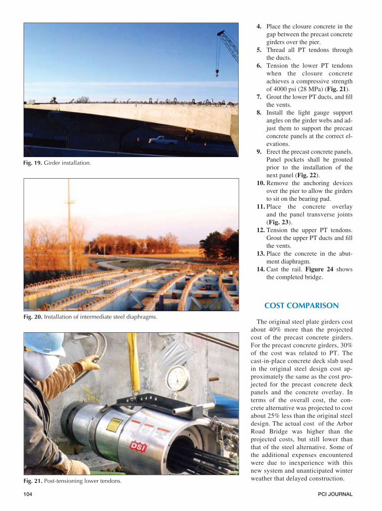
The precast concrete girders were produced at Concrete Industries Inc. using self-consolidating concrete. Figure 16 illustrates the girder rein-forcement, which includes the bottom unbonded PT monostrands, vertical shear WWR, and PT anchorage rein-forcement near the abutment end. Spi-ral reinforcement is used to confine the monostrands near the girder ends. Once the girder concrete is placed and achieves the specified concrete strength for the first-stage PT, the top external strands are tensioned, fol-lowed by tensioning of the bottom monostrands. Figure 17 illustrates the precast concrete girder in the precast-ing yard. It also shows the top external strands, the horizontal shear U-shaped bars, lifting inserts, and the PT ducts. The precast concrete deck panels were produced by the contractor at the bridge site.
CONSTRUCTION SEQUENCE
This suggested construction sequence was followed:
1. Construct the substructure. Note that steel beams are connected with the brackets at the pier for torsional restraint during the in-stallation of precast concrete girders and deck panels, which allows for one bearing pad at each girder line over the pier (Fig. 18).
2. Erect the girders span by span (Fig. 19). Anchor the girders to the abutment and pier. De- tension the top external strands after the girders are installed.
3. Install the internal and intermedi-ate diaphragms (Fig. 20).
Fig. 16.Girderreinforcement,elevationview.
Fig. 17.Precastconcretegirderstoredintheprecastingyard.
Fig. 18.Constructedpier.
104 PCI JOURNAL
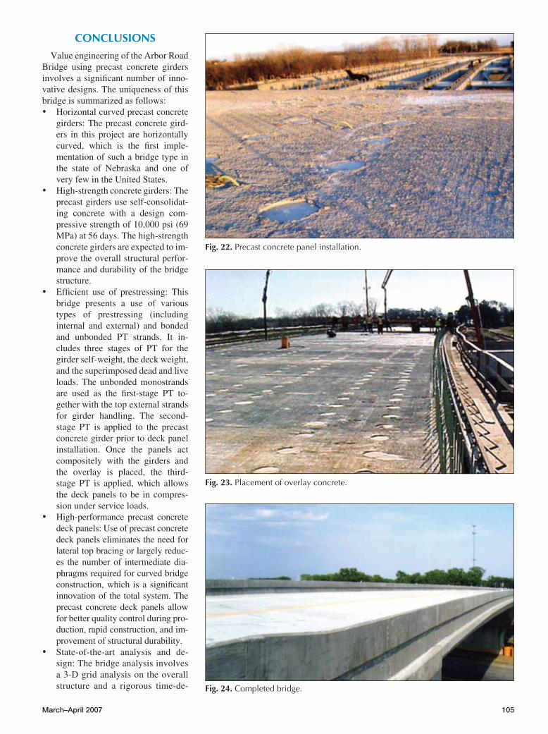
4. Place the closure concrete in the gap between the precast concrete girders over the pier.
5. Thread all PT tendons through the ducts.
6. Tension the lower PT tendons when the closure concrete achieves a compressive strength of 4000 psi (28 MPa) (Fig. 21).
7. Grout the lower PT ducts, and fill the vents.
8. Install the light gauge support angles on the girder webs and ad-just them to support the precast concrete panels at the correct el-evations.
9. Erect the precast concrete panels. Panel pockets shall be grouted prior to the installation of the next panel (Fig. 22).
10. Remove the anchoring devices over the pier to allow the girders to sit on the bearing pad.
11. Place the concrete overlay and the panel transverse joints (Fig. 23).
12. Tension the upper PT tendons. Grout the upper PT ducts and fill the vents.
13. Place the concrete in the abut-ment diaphragm.
14. Cast the rail. Figure 24 shows the completed bridge.
COST COMPARISON
The original steel plate girders cost about 40% more than the projected cost of the precast concrete girders. For the precast concrete girders, 30% of the cost was related to PT. The cast-in-place concrete deck slab used in the original steel design cost ap-proximately the same as the cost pro-jected for the precast concrete deck panels and the concrete overlay. In terms of the overall cost, the con-crete alternative was projected to cost about 25% less than the original steel design. The actual cost of the Arbor Road Bridge was higher than the projected costs, but still lower than that of the steel alternative. Some of the additional expenses encountered were due to inexperience with this new system and unanticipated winter weather that delayed construction.
Fig. 19.Girderinstallation.
Fig. 20.Installationofintermediatesteeldiaphragms.
Fig. 21.Post-tensioninglowertendons.
March–April 2007 10�
CONCLUSIONS
Value engineering of the Arbor Road Bridge using precast concrete girders involves a significant number of inno-vative designs. The uniqueness of this bridge is summarized as follows:• Horizontal curved precast concrete
girders: The precast concrete gird-ers in this project are horizontally curved, which is the first imple-mentation of such a bridge type in the state of Nebraska and one of very few in the United States.
• High-strength concrete girders: The precast girders use self-consolidat-ing concrete with a design com-pressive strength of 10,000 psi (69 MPa) at 56 days. The high-strength concrete girders are expected to im-prove the overall structural perfor-mance and durability of the bridge structure.
• Efficient use of prestressing: This bridge presents a use of various types of prestressing (including internal and external) and bonded and unbonded PT strands. It in-cludes three stages of PT for the girder self-weight, the deck weight, and the superimposed dead and live loads. The unbonded monostrands are used as the first-stage PT to-gether with the top external strands for girder handling. The second-stage PT is applied to the precast concrete girder prior to deck panel installation. Once the panels act compositely with the girders and the overlay is placed, the third-stage PT is applied, which allows the deck panels to be in compres-sion under service loads.
• High-performance precast concrete deck panels: Use of precast concrete deck panels eliminates the need for lateral top bracing or largely reduc-es the number of intermediate dia-phragms required for curved bridge construction, which is a significant innovation of the total system. The precast concrete deck panels allow for better quality control during pro-duction, rapid construction, and im-provement of structural durability.
• State-of-the-art analysis and de-sign: The bridge analysis involves a 3-D grid analysis on the overall structure and a rigorous time-de-
Fig. 22.Precastconcretepanelinstallation.
Fig. 23.Placementofoverlayconcrete.
Fig. 24.Completedbridge.
106 PCI JOURNAL
pendent analysis to account for creep effects. The girder design utilizes the strength design method for prestress at release, the strain compatibility approach for the flexural strength design, and the newly developed prestress loss solutions on high-strength con-crete girders. The latest research findings on the concrete confine-ment and the maximum spacing of horizontal shear reinforcement have also been incorporated into the bridge design.
• Efficient and economical overall design: The bridge presents an ef-ficient design with a span-to-depth ratio of 33, resulting in significant savings, not only including the di-rect cost savings over the original steel alternative, but also econo-mies in future maintenance.
• Competition with curved steel bridges: This project shows that it is technically and economically fea-sible for concrete superstructures to compete with curved steel bridges.
As a winner of the 2006 PCI Design Award for Best Bridge with Spans Greater than 135 ft, the project gar-nered these comments from the jury: “A truly innovative structure, it utilizes several precast concrete elements and demonstrates a unique application of precast, prestressed girders on a curved alignment.”
ACKNOWLEDGMENTS
The authors acknowledge the leader-ship and inspiration provided by Lyman Freemon, bridge engineer, NDOR, Lincoln, Neb. The support from Sam Fallaha, Fouad Jaber, Mark Traynow-icz, Babrak Niazi, and Steve Sabra at NDOR is greatly appreciated. Nick A. Meek at InfraStructure of Omaha, Neb., has provided valuable troubleshooting assistance. Acknowledgments go to contractor staff members Jim Jordan and Doug Williams at A. M. Cohron & Son Inc. of Atlantic, Iowa, for being extremely supportive and cooperative. The authors are also grateful for the help from Mark Lafferty at Concrete Industries Inc. of Lincoln and express their gratitude to the PCI Journal re-viewers and editors for their valuable suggestions.
REFERENCES1. Bridge Design Manual Steering Com-
mittee. 1997. Precast Prestressed Con-crete Bridge Design Manual. MNL-133. Chicago, IL: PCI.
2. American Association for State High-way and Transportation Officials (AASHTO). 2002. Standard Specifi-cations for Highway Bridges. 17th ed. Washington, DC: AASHTO.
3. AASHTO. AASHTO LRFD Bridge De-sign Specifications and 2004 and 2005 Interim Revisions. 3rd ed. Washington,
DC: AASHTO.
4. Nebraska Department of Roads (NDOR). 2001. Bridge Office Policies and Procedures (BOPP) Manual. Lin-coln, NE: NDOR.
5. Sun, C., A. Girgis, M. K. Tadros, and S. Badie. 2003. Structural Behavior of Flexural Members with High Per-formance Concrete. 3rd International Symposium on High Performance Con-crete PCI National Bridge Conference. CD-ROM. Chicago, IL: PCI.
6. Pessiki, Stephen. 2001. Proposed De-sign of High-Strength Spiral Rein-forcement in Compression Members. ACI Structural Journal, V. 98, No. 6 (November–December): pp. 799–810.
7. Tadros, M. K., N. Al-Omaishi, S. J. Seguirant, and J. G. Gallt. 2003. Pre-stress Losses in Pretensioned High-Strength Concrete Bridge Girders. Na-tional Cooperative Highway Research Program Report 496. Washington, DC: Transportation Research Board.
8. Lambert-Aikhionbare, N., and S. Tabsh. 2001. Confinement of High-strength Concrete with Welded Wire Reinforcement. ACI Structural Jour-nal, V. 98, No. 5 (September–October): pp. 677.
9. Saatcioglu, Murat, and Salim R. Razvi. 2002. Displacement-Based Design of Reinforced Concrete Columns for Confinement. ACI Structural Jour-nal, V. 99, No. 1 (January–February): pp. 3–11.