Embed Size (px)
Citation preview

VAF SeriesCompressed Air Filters
20–780 CFM
industry revolves around

World Class Filtration
VAF Series Filters provide your compressed air system with premium quality filtration for the three typical contaminant types
1) Solid particles come from ambient air contaminants like dust and from rusted, oxidized pipework. They will cause pneumatic equipment to malfunction, cause instrument and control failures, and contaminate end products.
2) Condensed water droplets come from the humidity in ambient air. Water will oxidize pipework and pneumatic equipment, ruin paint finishes and end products.
3) Liquid oil and oil vapors are introduced by compressor lubricants and by hydrocarbon vapors present in ambient air. Oil-free compressed air is particularly important in food and pharmaceutical processes.
Filter Grade Description
Filtration* ISO 8573.1Quality Classes***Water
Droplets**ppm w/w
Solid Particulates
micron
Oil Removal ppm w/w solids oil
A Water Separator 30,000 - - - -
B Separator/Filter 25,000 3 5 3 5
C General Purpose 2,000 1 1 2 4
D Dry Particulate - 1 - 2 -
E High Efficiency Oil Removal 1,000 0.01 0.008 1 1
F Maximum Efficiency Oil Removal 100 0.01 0.0008 1 1
G Oil Vapor Removal - 0.01 0.003 1 1*Tested to CAGI ADF400 & ADF500, **Maximum inlet liquid load, ***Complete ISO 8573.1 Reference Table on page 5
Comply with Pressure Vessel Directives WorldwideVAF Series Filters utilize housings which conform to most major pressure vessel directives in the Americas, Europe, and Asia.

Gauge •Standard on 100–780 scfm models
•Dual gauge face allows housings to be mounted in any flow direction
• Indicates element change-out based on differential pressure
•Large easy-to-read gauge face
•Remote mounting possible
Simple Maintenance•1/8” turn, self-locking bayonet head to bowl connection
(up through 1” connection sizes)
•Audible warning by escaping air if housing is not depressurized before disassembly
•Ribbed bowls allow use of C-spanner
•Color-coded elements for easy identification
Modular Housings Save Space and Time •Standard on 20–780 scfm models
•Large flow paths reduce pressure drop
•Chromated and epoxy powder painted (interior and exterior) add durability and corrosion resistance
•MWP 300 psig (21 bar)
•Can be mounted for left or right entry
•High-quality aluminium, zinc, and steel materials
Element Grades Offer Superior Filtration •Large effective surface areas ensure high capture rates
•Large open areas minimize pressure drop
•Silicone-free, withstand temperatures to 150°F (66°C)
•Push-on elements for quick replacement
•Corrosion resistant, stainless steel cores
Internal Automatic Drains •Reliable discharge of condensate
•Pilot operated, pneumatically actuated, particulate-resistant mechanism
•Viton seals and inlet screen for additional protection
Slide Indicator •Standard on 20–60 scfm models
•Changes color based on differential pressure
Energy Saving Element Monitor•Optional on grades B through G
•Three modes determine element change: time, differential pressure, element performance
•Selectable filter performance settings
•Maximizes system efficiencies
•Reduces operating costs
Innovative Features
1
1
2
2
3
3
4
4
5
5
6
6
7
7

Filter Elements for all Grades of Filtration
Installation: after an air compressors’ (or a stand-alone) aftercooler Design: One-stage filtration with two stainless steel orifice tubes. Labyrinth style air flow path removes liquid water by
forcing abrupt directional changes. Performance*: Handles bulk liquid inlet loads to 30,000 ppm w/w and provides 10 micron solid particulate separation. Efficient to flows as low as 5% of rated flow.
Grade A - Water Separator
Installation: after an air compressors’ (or a stand-alone) aftercooler or as a prefilter to a refrigerated dryerDesign: Two-stage filtration with first stage of two stainless steel orifice tubes which remove bulk liquids and solid particulates to 10 micron. Second stage has in-depth
coalescing fiber media which captures solid particulates to 3 micron. Performance*: Handles bulk liquid inlet loads to 25,000 ppm w/w, provides 3 micron solid particulate filtration and oil removal to 5 ppm.
Grade B - Separator/Filter
Installation: Dry, solid particulate afterfilter for heatless desiccant dryersDesign: Two-stage filtration with life-prolonging outside/in air flow with first stage of alternate layers of fiber media and a media screen capturing large particulates. Second
stage captures finer particulates. Not designed for any liquid loading. Performance*: Provides 1 micron solid particulate filtration of desiccant dust.
Grade D - Dry Particulate Filter
Installation: 1 micron particulate prefilter for refrigerated dryers and high efficiency oil removal filters.Design: Two-stage filtration with a first stage of multiple layers of fiber media which pre-filter the air. Second stage has in-depth coalescing fiber media which coalesces oil
aerosols and removes finer particulates to 1 micron.Performance*: Handles bulk liquid inlet loads to 2,000 ppm w/w, provides 1 micron solid particulate filtration and oil removal to 1 ppm.
Grade C - General Purpose Filter
Installation: Prefilter to desiccant and membrane dryers, afterfilter to refrigerated dryers and stand-alone oil removal at the point-of-use of compressed air.Design: Two-stage filtration with a first stage of multiple layers of fiber media which prefilter the air. Second stage has in-depth coalescing fiber media which coalesces oil aerosols.
Includes an outer-coated, closed cell foam sleeve. Performance*: Handles bulk liquid water inlet loads to 1,000 ppm w/w and provides 0.008 ppm oil aerosol removal and 0.01 micron solid particulate separation.
Grade E - High Efficiency Oil Removal Filter
Installation: Prefilter to desiccant and membrane dryers with a Grade C prefilter, oil-free air applications.Design: Two-stage filtration with a first stage of a coated, closed-cell foam sleeve which acts as a prefilter and flow disperser. Second stage has in-depth coalescing fiber media
which coalesces fine oil aerosols. Includes an outer-coated, closed cell foam sleeve. Performance*: Handles bulk liquid water inlet loads to 100 ppm w/w and provides 0.0008 ppm oil aerosol removal and 0.01 micron solid particulate separation.
Grade F - Maximum Efficiency Oil Removal Filter
Installation: Afterfilter to high efficiency liquid oil removal filters for true oil-free applications.Design: Two-stage filtration with a generously-sized first stage of a stabilized bed of carbon particles which remove the majority of the oil vapor. Second stage has multiple layers of fiber media with bonded microfine carbon particles which
remove the remaining oil vapors. Includes an outer-coated, closed cell foam sleeve which prevents fiber migration. Performance**: No liquid should be present at filter inlet. Provides 0.003 ppm w/w oil (as a vapor) removal and 0.01 micron solid particulate separation.
Grade G - Oil Vapor Removal Filter
* Filter efficiencies have been established in accordance with CAGI standard ADF400 and are based on 100°F (38°C) inlet temperature** Filter efficiency has been established in accordance with CAGI standard ADF500 and is based on 100°F (38°C) inlet temperature
Compressed air systems continually challenge filtration with moisture, solid particulates, and liquid oil or oil vapors. VAF Series filter elements represent state-of-the-art filter designs which allow for custom filtration at every installation. Inside-to-out air flow maximizes filtration efficiency
Two-stage filtration ensures long element lifeStainless steel inner and outer cores add structural integrity Uniquely blended coalescing fiber media design Coated foam sleeves provide protection against chemical attack 100% silicone free, withstand temperatures to 150°F (66°C)

ISO 8573.1 Quality ClassesISO8573.1wasdevelopedin1992byISO(InternationalOrganizationforStandardization)tohelpplantengineersspecifydesiredcompressedairqualitygloballybyproviding“QualityClasses”forsolidparticulates,humidityandoil.Qualityclassesprovideengineerswithaninternationallyacceptedunitofmeasure.Atypicalpharmaceuticalplant,forexample,wouldhaveacompressedairspecificationofISOQualityClasses1.2.1.Thisisequivalentto0.1micronparticulatefiltration,-40°F(-40°C)dewpoint,and0.008ppm(0.01mg/m³)oilfiltration.
Nomatterwhatlanguageisspokenandwhatunitofmeasureisused,usingISO8573.1AirQualityClassesensuresthatyourfactorywillgetthecompressedairqualityyouspecified.
QualityClasses
Solid Contaminants(maximum particle size in microns)
Maximum Pressure
Dew Points°F (°C)
Maximum Oil Content
(droplets, aerosols, and vapor
ppm w/w (mg/m³)
1 0.1 -94 (-70) 0.008 (0,01)
2 1 -40 (-40) 0.08 (0,1)
3 5 -4 (-20) 0.8 (1)
4 15 38 (3) 4 (5)
5 40 45 (7) 21 (25)
6 – 50 (10) –
Air Quality/Pressure Drop Table
FilterGrade Description
Pressure Drop at Rated Conditions
psid (kgf/cm²)
dry wet
A Water Separator 0.8 (0.06) 0.8 (0.06)
B Separator/Filter 1 (0.07) 1.5 (0.11)
C General Purpose 1 (0.07) 2 (0.14)
D Dry Particulate 1 (0.07) –
E High Efficiency Oil Removal 1 (0.07) 3 (0.21)
F Max. Efficiency Oil Removal 2 (0.14) 6 (0.42)
G Oil Vapor Removal 1 (0.07) –

ISO 8573.1Air Quality Class System ∆P*
Application
Solids Moisture Oil psi bar
3 6 5 <5 <0,35 Body shops, sand blasting
1 6 1 <8 <0,56 Large pneumatic tools, spray painting
1 4 1 <8 <0,56Powder painting, fine pneumatictools, air gauging & conveying,
pneumatic instruments & controls
1 4 1 <11 <0,75 Food packaging, cosmetics, photo labs, textile looms
1 2-5 1 <10 <0,68Telephone cable, printing,photo labs, spray painting,
dental, laboratory instruments
1 1-3 1 <10 <0,68Air lines exposed to freezing
ambient conditions, pharmaceutical,
chemical, powder paint
1 2-3 1 <15 <1,02
Food processing, dairies, breweries,
air in direct contact with foods, microchips, optics, medicines,
point-of-use filtration
* Efficiencies per CAGI standards ADF100 and ADF400 and wetted element conditions.
Maintain System Pressure: Create a Custom Air Treatment System
Maximize system pressure by choosing the combination of hydrovane air treatment products which perfectly match your applications’ requirements.
Grades F & G
Grade E
Membrane Dryers
Grade D
Heatless Desiccant Dryers
Heated Desiccant DryersGrades F & GHigh Temp.
Particulate Filter
Grade ACompressor
Refrigerated Dryers
High Temp. Refrigerated
Dryers
Grades C & E
Grade E
Oil Water Separator
ModelCapacity SCFM
(M³/MIN)
ConnectionsNPT/
ANSI FLG.
Standard Features
Filter Grades
Max Pressure (psig) (KGF/
CM²) Temp ˚F (˚C)
Dimensions Replacement Element
Manual Drain
With D or L
Height in (MM)
Width in (MM)
WeightLB (KG)A B C,E,F D G Model_Grade QTY.
Modular Type Housings
VAF20 20 (0.57) 3/8" NPTF D DP DP P (2) 300 250 21 150 (66) 8.15 (207) 4.13 (105) 4.2 (1.9) C20_E 1
VAF35 35 (1.00) 1/2" NPTF D DP DP P (2) 300 250 21 150 (66) 11.05 (281) 4.13 (105) 8.1 (3.7) C35_E 1
VAF60 60 (1.72) 1/2" NPTF D DP DP P (2) 300 250 21 150 (66) 13.4 (340) 4.13 (105) 8.5 (3.9) C60_E 1
VAF100 100 (2.9) 3/4" NPTF D DG DG G (2) 300 250 21 150 (66) 15.32 (389) 5.25 (133) 6.3 (2.9) C100_E 1
VAF170 170 (4.9) 1" NPTF D DG DG G (2) 300 250 21 150 (66) 19.57 (497) 5.25 (133) 6.9 (3.1) C170_E 1
VAF250 250 (7.2) 1 1/2" NPTF (1) G (1) DG G (2) 300 250 21 150 (66) 22.8 (579) 6.44 (164) 10.2 (4.6) C250_E 1
VAF375 375 (11) 1 1/2" NPTF (1) G (1) DG G (2) 300 250 21 150 (66) 27.29 (693) 6.44 (164) 11.3 (5.1) C375_E 1
VAF485 485 (14) 2" NPTF (1) G (1) DG G (2) 300 250 21 150 (66) 31.08 (789) 7.63 (194) 28 (12.7) C485_E 1
VAF625 625 (18) 2 1/2" NPTF (1) G (1) DG G (2) 300 250 21 150 (66) 36.83 (935) 7.63 (194) 33 (15.0) C625_E 1
VAF780 780 (22) 2 1/2" NPTF (1) G (1) DG G (2) 300 250 21 150 (66) 42.96 (1091) 7.63 (194) 38 (17.2) C780_E 1
(1) Drain plugs standard. Externally mounted automatic drains are available.(2) Time-based Element Monitor recommended(3) ASME coded pressure vessels
D - Internal Automatic Drain MechanismE - Electric Demand DrainP - Differential Pressure Slide IndicatorG - Differential Pressure Gauge Indicator
L - Liquid Level IndicatorS - Corrosion Proof Stainless Steel elementM - Element Monitor
Features:A - Mechanical Separator (bulk liquid)B - Separator/Filter (3 micron and bulk liquid)C - Air Line Filter (1 micron)D - Dry Desiccant Afterfilter (1 micron)
E - High Efficiency Oil Removal Filter (0.008 ppm)F - Maximum Efficiency Oil Removal
Filter (0.0008 ppm)G - Oil Vapor Removal Filter (activated carbon)
Filter Grades:
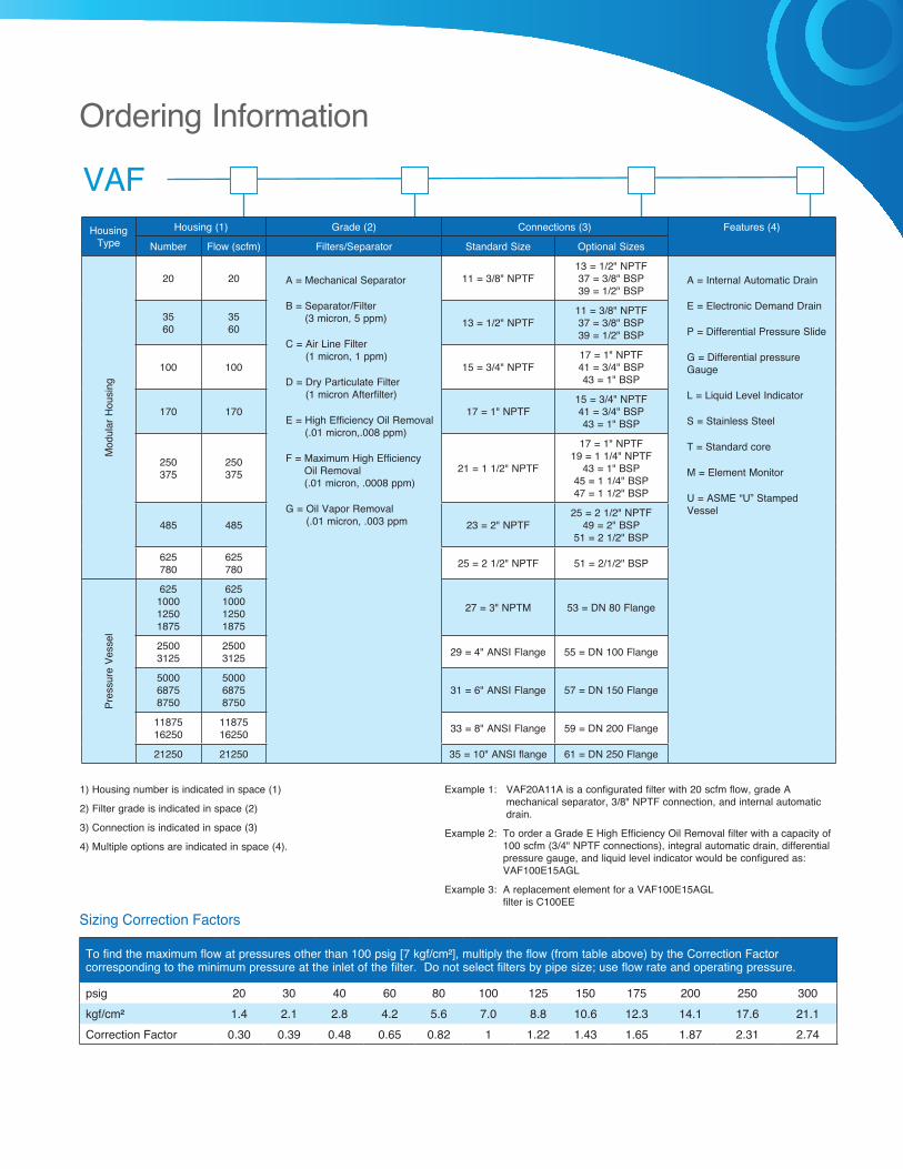
Housing Type
Housing (1) Grade (2) Connections (3) Features (4)
Number Flow (scfm) Filters/Separator Standard Size Optional Sizes
Mod
ular
Hou
sing
20 20 A = Mechanical Separator
B = Separator/Filter (3 micron, 5 ppm)
C = Air Line Filter (1 micron, 1 ppm)
D = Dry Particulate Filter (1 micron Afterfilter)
E = High Efficiency Oil Removal (.01 micron,.008 ppm)
F = Maximum High Efficiency Oil Removal (.01 micron, .0008 ppm)
G = Oil Vapor Removal (.01 micron, .003 ppm
11 = 3/8" NPTF13 = 1/2" NPTF37 = 3/8" BSP39 = 1/2" BSP
A = Internal Automatic Drain
E = Electronic Demand Drain
P = Differential Pressure Slide
G = Differential pressure Gauge
L = Liquid Level Indicator
S = Stainless Steel
T = Standard core
M = Element Monitor
U = ASME “U” Stamped Vessel
35 60
35 60 13 = 1/2" NPTF
11 = 3/8" NPTF37 = 3/8" BSP39 = 1/2" BSP
100 100 15 = 3/4" NPTF17 = 1" NPTF41 = 3/4" BSP43 = 1" BSP
170 170 17 = 1" NPTF15 = 3/4" NPTF41 = 3/4" BSP43 = 1" BSP
250 375
250 375 21 = 1 1/2" NPTF
17 = 1" NPTF19 = 1 1/4" NPTF
43 = 1" BSP45 = 1 1/4" BSP47 = 1 1/2" BSP
485 485 23 = 2" NPTF25 = 2 1/2" NPTF
49 = 2" BSP51 = 2 1/2" BSP
625 780
625 780 25 = 2 1/2" NPTF 51 = 2/1/2" BSP
Pres
sure
Ves
sel
625 1000 1250 1875
625 1000 1250 1875
27 = 3" NPTM 53 = DN 80 Flange
2500 3125
2500 3125 29 = 4" ANSI Flange 55 = DN 100 Flange
5000 6875 8750
5000 6875 8750
31 = 6" ANSI Flange 57 = DN 150 Flange
11875 16250
11875 16250 33 = 8" ANSI Flange 59 = DN 200 Flange
21250 21250 35 = 10" ANSI flange 61 = DN 250 Flange
VAF
Sizing Correction Factors
To find the maximum flow at pressures other than 100 psig [7 kgf/cm²], multiply the flow (from table above) by the Correction Factor corresponding to the minimum pressure at the inlet of the filter. Do not select filters by pipe size; use flow rate and operating pressure.
psig 20 30 40 60 80 100 125 150 175 200 250 300kgf/cm² 1.4 2.1 2.8 4.2 5.6 7.0 8.8 10.6 12.3 14.1 17.6 21.1Correction Factor 0.30 0.39 0.48 0.65 0.82 1 1.22 1.43 1.65 1.87 2.31 2.74
1) Housing number is indicated in space (1)
2) Filter grade is indicated in space (2)
3) Connection is indicated in space (3)
4) Multiple options are indicated in space (4).
Example 1: VAF20A11A is a configurated filter with 20 scfm flow, grade A mechanical separator, 3/8" NPTF connection, and internal automatic drain.
Example 2: To order a Grade E High Efficiency Oil Removal filter with a capacity of 100 scfm (3/4" NPTF connections), integral automatic drain, differential pressure gauge, and liquid level indicator would be configured as: VAF100E15AGL
Example 3: A replacement element for a VAF100E15AGL filter is C100EE
Ordering Information

©2010 Gardner Denver, Inc. Printed in U.S.A.HY-AT-VAF 1st Ed. 6/10
Please recycle after use.
www.hydrovaneproducts.com
hydrovane USA 1301 North Euclid Avenue Princeton, IL 61356 United States of America
Tel (866) 994-8807 Fax (800) 443-7790
hydrovane Canada 871 Cranberry Court Oakville, Ontario L6L 6J7 Canada
Tel (905) 847-0688 Fax (905) 847-8124
Member
8
ACCREDITED
Protect the investment in hydrovane Regular maintenance and service of hydrovane product is critical to the performance and longevity of the equipment. Only hydrovane can provide the assurance that the investment will provide a lifetime of productivity.
ReliabilityOnly hydrovane can provide aftermarket parts and services that are engineered for use in hydrovane products. The parts and lubricant have been tested under rigorous conditions at the factory to the highest quality standards.
Performance Only hydrovane can provide aftermarket parts designed specifically for the hydrovane product. Use of OEM parts ensures that the investment in hydrovane will continue to perform year in and year out with the same reliability and efficiency.
Ease of Doing Business Only hydrovane can provide the peace of mind of turning to one supplier and one source for all aftermarket needs. hydrovane has the support network in place to handle all customer service, service and technical support needs.
ValueOnly hydrovane can provide the high quality aftermarket parts and services for the life of the investment in hydrovane. Proper care of the hydrovane product is vital to the equipment’s performance and efficiency. Lean on a trusted source — hydrovane.
Aftermarket Parts & Lubricants