Embed Size (px)
Citation preview
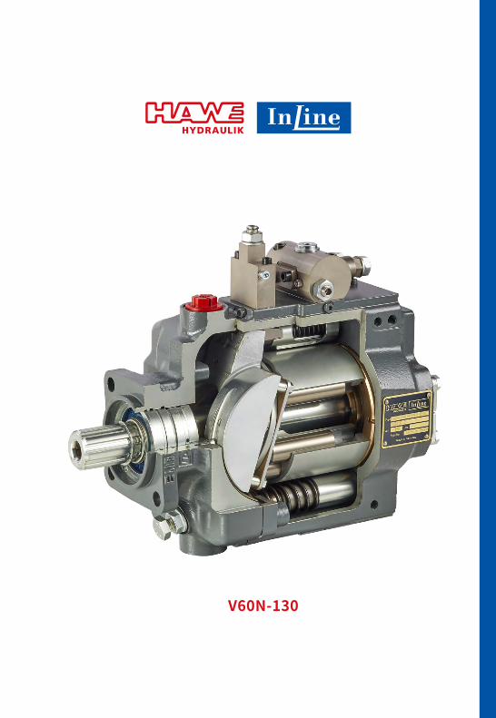
V60N-130
162 www.hawe-inline.com
© by HAWE InLine Hydraulik GmbH.The forwarding and reproduction of this document, as well as the use and communication of its contents, are forbidden unless expressely permitted. Any breach or infringement will result in liability for damages. All rights reserved concerning patent or utility model registrations.
163www.hawe-inline.com
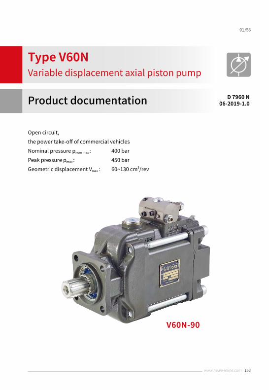
Open circuit, the power take-off of commercial vehiclesNominal pressure pnom max : 400 barPeak pressure pmax : 450 barGeometric displacement Vmax : 60~130 cm3/rev
Type V60NVariable displacement axial piston pump
Product documentation D 7960 N06-2019-1.0
/5801
V60N-90
Type V60N | 06-2019-1.0 | D 7960 N/58
164 www.hawe-inline.com
02
1 Overview: variable displacement axial piston pump types V60N ……………………………… 03
2 Available versions, main data ………………………………………………………………………… 042.1 Basic version ……………………………………………………………………………………………… 042.2 Controller switching symbols …………………………………………………………………………… 10
3 Parameters ………………………………………………………………………………………………… 143.1 General ……………………………………………………………………………………………………… 143.2 Planning information for parameters …………………………………………………………………… 163.3 Characteristic curves ……………………………………………………………………………………… 173.4 Controller characteristic curves ………………………………………………………………………… 18
4 Dimensions ………………………………………………………………………………………………… 204.1 Basic pump ………………………………………………………………………………………………… 204.1.1 Type V60N-060 ……………………………………………………………………………………………… 204.1.2 Type V60N-090 ……………………………………………………………………………………………… 264.1.3 Type V60N-110 ……………………………………………………………………………………………… 334.1.4 Type V60N-130 ……………………………………………………………………………………………… 404.2 Controllers and intermediate plates …………………………………………………………………… 46
5 Installation information ………………………………………………………………………………… 49 5.1 General information ……………………………………………………………………………………… 495.2 Ports ………………………………………………………………………………………………………… 505.3 Installation positions ……………………………………………………………………………………… 515.4 Tank installation …………………………………………………………………………………………… 52
6 Installation, operation and maintenance information …………………………………………… 53 6.1 Designated use …………………………………………………………………………………………… 536.2 Assembly information …………………………………………………………………………………… 536.3 Operating instructions …………………………………………………………………………………… 53
7 Accessories, spare parts and separate components ……………………………………………… 547.1 Discontinued controller units …………………………………………………………………………… 547.1.1 Available versions ………………………………………………………………………………………… 547.2 Suction intakes …………………………………………………………………………………………… 567.3 Coupling flange for propshafts ………………………………………………………………………… 57
Contents
Type V60N | 06-2019-1.0 | D 7960 N /58
165www.hawe-inline.com
03
Overview: variable displacement axial piston pump types V60N1
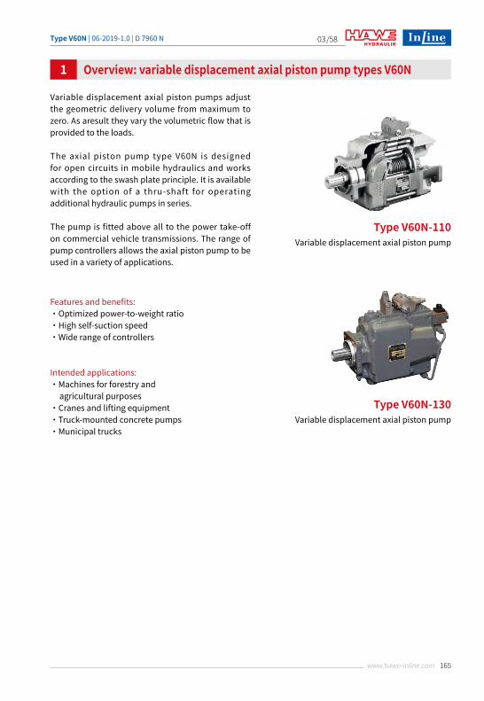
Variable displacement axial piston pumps adjust the geometric delivery volume from maximum to zero. As aresult they vary the volumetric flow that is provided to the loads.
The axial piston pump type V60N is designed for open circuits in mobile hydraulics and works according to the swash plate principle. It is available with the option of a thru-shaft for operating additional hydraulic pumps in series.
The pump is fitted above all to the power take-off on commercial vehicle transmissions. The range of pump controllers allows the axial piston pump to be used in a variety of applications.
Features and benefits:・Optimized power-to-weight ratio・High self-suction speed・Wide range of controllers
Intended applications:・Machines for forestry and agricultural purposes・Cranes and lifting equipment・Truck-mounted concrete pumps・Municipal trucks
Type V60N-110 Variable displacement axial piston pump
Type V60N-130 Variable displacement axial piston pump
Type V60N | 06-2019-1.0 | D 7960 N/58
166 www.hawe-inline.com
04
Available versions, main data
2.1 Basic version
2
Circuit symbol:
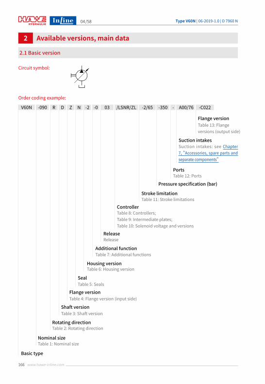
Order coding example:
V60N -2/65-090 R D Z N -2 -0 03 /LSNR/ZL -350
Controller
Stroke limitation
Release
Additional function
Housing version
Seal
Flange version
Shaft version
Rotating direction
Nominal size
Basic type
Pressure specification (bar)
Ports
Table 11: Stroke limitations
Table 12: Ports
Table 8: Controllers; Table 9: Intermediate plates; Table 10: Solenoid voltage and versions
Release
Table 7: Additional functions
Table 6: Housing version
Table 5: Seals
Table 4: Flange version (input side)
Table 3: Shaft version
Table 2: Rotating direction
Table 1: Nominal size
-
Flange versionTable 13: Flange versions (output side)
-C022
Suction intakesSuction intakes: see Chapter 7, "Accessories, spare parts and separate components"
A00/76Coding LSNR Coding LSNRT
Coding QNR
X
LS P R A A P
ST
L
S
X
LS P R A A P
ST
L
S
X
LS P R A A
PST
L
S
Type V60N | 06-2019-1.0 | D 7960 N /58
167www.hawe-inline.com
05
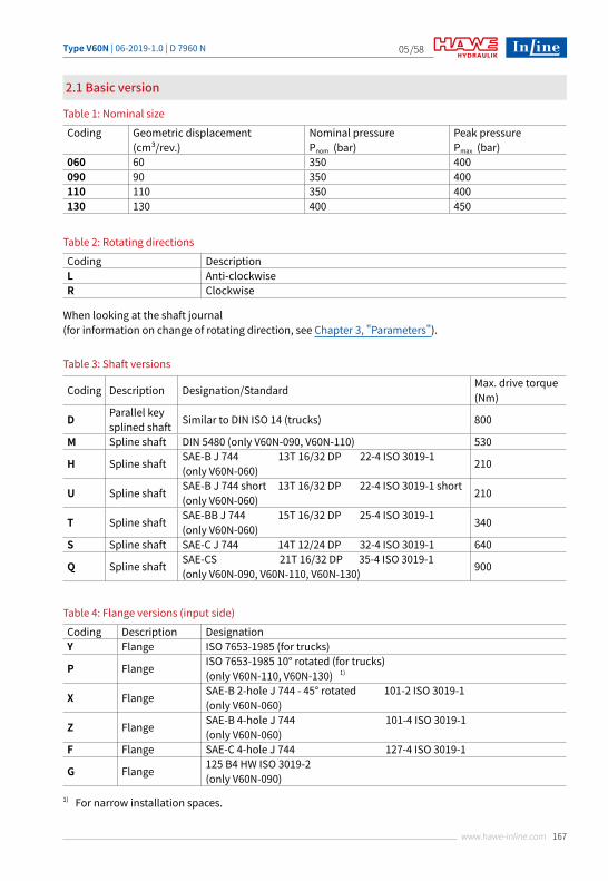
2.1 Basic version
Table 1: Nominal size
Table 2: Rotating directions
Table 3: Shaft versions
Coding Geometric displacement (cm³/rev.)
Nominal pressure Pnom (bar)
Peak pressure Pmax (bar)
060 60 350 400090 90 350 400110 110 350 400130 130 400 450
Coding DescriptionL Anti-clockwiseR Clockwise
Coding Description Designation/Standard Max. drive torque (Nm)
D Parallel keysplined shaft Similar to DIN ISO 14 (trucks) 800
M Spline shaft DIN 5480 (only V60N-090, V60N-110) 530
H Spline shaft SAE-B J 744 13T 16/32 DP 22-4 ISO 3019-1 (only V60N-060) 210
U Spline shaft SAE-B J 744 short 13T 16/32 DP 22-4 ISO 3019-1 short (only V60N-060) 210
T Spline shaft SAE-BB J 744 15T 16/32 DP 25-4 ISO 3019-1 (only V60N-060) 340
S Spline shaft SAE-C J 744 14T 12/24 DP 32-4 ISO 3019-1 640
Q Spline shaft SAE-CS 21T 16/32 DP 35-4 ISO 3019-1 (only V60N-090, V60N-110, V60N-130) 900
Table 4: Flange versions (input side)
Coding Description DesignationY Flange ISO 7653-1985 (for trucks)
P Flange ISO 7653-1985 10° rotated (for trucks)(only V60N-110, V60N-130) 1)
X Flange SAE-B 2-hole J 744 - 45° rotated 101-2 ISO 3019-1(only V60N-060)
Z Flange SAE-B 4-hole J 744 101-4 ISO 3019-1(only V60N-060)
F Flange SAE-C 4-hole J 744 127-4 ISO 3019-1
G Flange 125 B4 HW ISO 3019-2(only V60N-090)
When looking at the shaft journal (for information on change of rotating direction, see Chapter 3, "Parameters").
1) For narrow installation spaces.
Type V60N | 06-2019-1.0 | D 7960 N/58
168 www.hawe-inline.com
06
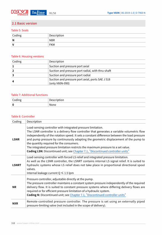
2.1 Basic version
Table 5: Seals
Table 6: Housing versions
Table 7: Additional functions
Coding DescriptionN NBRV FKM
Coding Description1 Suction and pressure port axial2 Suction and pressure port radial, with thru-shaft3 Suction and pressure port radial
4 Suction and pressure port axial, ports SAE J 518(only V60N-090)
Coding Description0 None
Table 8: Controller
Coding Description
LSNR
Load-sensing controller with integrated pressure limitation.The LSNR controller is a delivery flow controller that generates a variable volumetric flow independently of the rotation speed. It sets a constant difference between the load pressure and pump pressure by continuously adapting the geometric displacement of the pump to the quantity required for the consumers.The integrated pressure limitation restricts the maximum pressure to a set value.Coding LSN: Discontinued unit; see Chapter 7.1, "Discontinued controller units"
LSNRT
Load-sensing controller with forced LS relief and integrated pressure limitation.As well as the LSNR controller, the LSNRT contains internal LS signal relief. It is suited to hydraulic systems whose LS relief does not take place in proportional directional spool valves.Internal leakage current Q ≤ 1.5 lpm
NR
Pressure controller, adjustable directly at the pump.The pressure controller maintains a constant system pressure independently of the required delivery flow. It is suited to constant pressure systems where differing delivery flows are required or for efficient pressure limitation of a hydraulic system.Coding N: Discontinued unit; see Chapter 7.1, "Discontinued controller units"
NXR Remote-controlled pressure controller. The pressure is set using an externally piped pressure-limiting valve (not included in the scope of delivery).
Type V60N | 06-2019-1.0 | D 7960 N /58
169www.hawe-inline.com
07
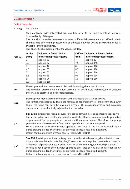
2.1 Basic version
Table 8: Controller
Coding Description
QNR/...
Flow controller with integrated pressure limitation for setting a constant flow rate independently of the speed.The quantity controller generates a constant differential pressure via an orifice in the P channel. The differential pressure can be adjusted between 20 and 55 bar; the orifice is available in various gradings.This allows flexible adjustment of the volumetric flow.
Orifice (mm)
Volumetric flow at 20 bardifferential pressure (lpm)
Orifice(mm)
Volumetric flow at 20 bardifferential pressure (lpm)
3 approx. 23 7 approx. 1273.5 approx. 32 7.5 approx. 1464 approx. 42 8 approx. 1664.5 approx. 53 8.5 approx. 1885 approx. 65 9 approx. 2105.5 approx. 65 9.5 approx. 2346 approx. 94 10 approx. 2606.5 approx. 110
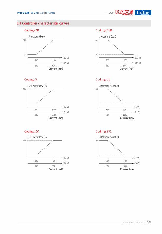
PRElectric proportional pressure controller with increasing characteristic curve.The maximum pressure and minimum pressure can be adjusted mechanically; in between these values, electrical adjustment is possible.
P1R
Electric proportional pressure controller with decreasing characteristic curve.The controller is specifically developed for fan and generator drives. In the event of a power failure, the pump generates the maximum pressure. The maximum pressure and minimum pressure can be mechanically adjusted at the controller.
/ V
Size 130: Electric proportional delivery flow controller with increasing characteristic curve.The V controller is an electrically actuated controller that sets an appropriate geometric displacement for the pump in accordance with a current value. Therefore, the pump generates a variable volumetric flow that is dependent on the rotation speed.For use in open centre systems with operating pressures of < 70 bar, an external supply pump or pump pre-load valve must be provided to ensure reliable adjustment.Only in combination with pressure control (codings NR or NXR)
/ V1
Size 130: Electric proportional delivery flow controller with decreasing characteristic curve.In comparison with the /V controller, the /V1 controller has a negative characteristic curve, i.e. in the event of power failure, the pump operates at a maximum geometric displacement.For use in open centre systems with operating pressures of < 70 bar, an external supply pump or pump pre-load valve must be provided to ensure reliable adjustment.Only in combination with pressure control (codings NR or NXR)
Type V60N | 06-2019-1.0 | D 7960 N/58
170 www.hawe-inline.com
08
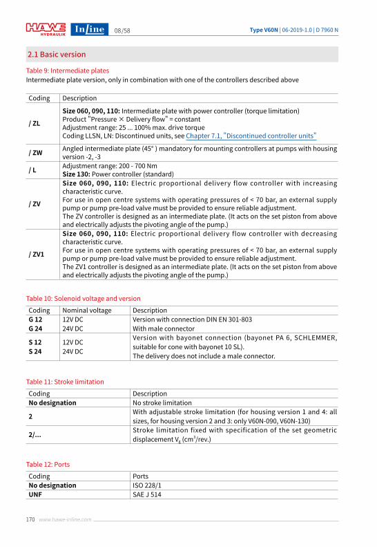
2.1 Basic version
Table 9: Intermediate platesIntermediate plate version, only in combination with one of the controllers described above
Coding Description
/ ZL
Size 060, 090, 110: Intermediate plate with power controller (torque limitation)Product "Pressure × Delivery flow" = constantAdjustment range: 25 ... 100% max. drive torqueCoding LLSN, LN: Discontinued units, see Chapter 7.1, "Discontinued controller units"
/ ZW Angled intermediate plate (45° ) mandatory for mounting controllers at pumps with housing version -2, -3
/ L Adjustment range: 200 - 700 NmSize 130: Power controller (standard)
/ ZV
Size 060, 090, 110: Electric proportional delivery flow controller with increasing characteristic curve.For use in open centre systems with operating pressures of < 70 bar, an external supply pump or pump pre-load valve must be provided to ensure reliable adjustment.The ZV controller is designed as an intermediate plate. (It acts on the set piston from above and electrically adjusts the pivoting angle of the pump.)
/ ZV1
Size 060, 090, 110: Electric proportional delivery flow controller with decreasing characteristic curve.For use in open centre systems with operating pressures of < 70 bar, an external supply pump or pump pre-load valve must be provided to ensure reliable adjustment.The ZV1 controller is designed as an intermediate plate. (It acts on the set piston from above and electrically adjusts the pivoting angle of the pump.)
Table 10: Solenoid voltage and version
Coding Nominal voltage DescriptionG 12G 24
12V DC24V DC
Version with connection DIN EN 301-803With male connector
S 12S 24
12V DC24V DC
Version with bayonet connection (bayonet PA 6, SCHLEMMER, suitable for cone with bayonet 10 SL).The delivery does not include a male connector.
Table 11: Stroke limitation
Table 12: Ports
Coding DescriptionNo designation No stroke limitation
2 With adjustable stroke limitation (for housing version 1 and 4: all sizes, for housing version 2 and 3: only V60N-090, V60N-130)
2/... Stroke limitation fixed with specification of the set geometric displacement Vg (cm3/rev.)
Coding PortsNo designation ISO 228/1UNF SAE J 514
Type V60N | 06-2019-1.0 | D 7960 N /58
171www.hawe-inline.com
09
2.1 Basic version
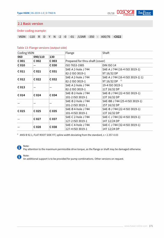
Order coding example:
Table 13: Flange versions (output side)
Note: Pay attention to the maximum permissible drive torque, as the flange or shaft may be damaged otherwise.
Note:An additional support is to be provided for pump combinations. Other versions on request.
1) ANSI B 92.1, FLAT ROOT SIDE FIT, spline width deviating from the standard, s = 2.357-0.03
Coding V60N Flange Shaft060 090/110 130C 001 C 002 C 003 Prepared for thru-shaft (cover)C 010 -- C 030 ISO 7653-1985 DIN ISO 14
C 011 C 021 C 031 SAE-A 2-hole J 74482-2 ISO 3019-1
SAE-A J 744 (16-4 ISO 3019-1)9T 16/32 DP
C 012 C 022 C 032 SAE-A 2-hole J 74482-2 ISO 3019-1
SAE-A J 744 (16-4 ISO 3019-1) 1)9T 16/32 DP 1)
C 013 -- -- SAE-A 2-hole J 74482-2 ISO 3019-1
19-4 ISO 3019-111T 16/32 DP
C 014 C 024 C 034 SAE-B 2-hole J 744101-2 ISO 3019-1
SAE-B J 744 (22-4 ISO 3019-1)13T 16/32 DP
-- -- -- SAE-B 2-hole J 744101-2 ISO 3019-1
SAE-BB J 744 (25-4 ISO 3019-1)15T 16/32 DP
C 015 C 025 C 035 SAE-B 4-hole J 744101-4 ISO 3019-1
SAE-B J 744 (22-4 ISO 3019-1)13T 16/32 DP
-- C 027 C 037 SAE-C 2-hole J 744127-2 ISO 3019-1
SAE-C J 744 (32-4 ISO 3019-1)14T 12/24 DP
-- C 028 C 038 SAE-C 4-hole J 744127-4 ISO 3019-1
SAE-C J 744 (32-4 ISO 3019-1)14T 12/24 DP
V60N -110 R D Y N -2 -0 -01 /LSNR -350 - -C022A00/76
Type V60N | 06-2019-1.0 | D 7960 N/58
172 www.hawe-inline.com
10
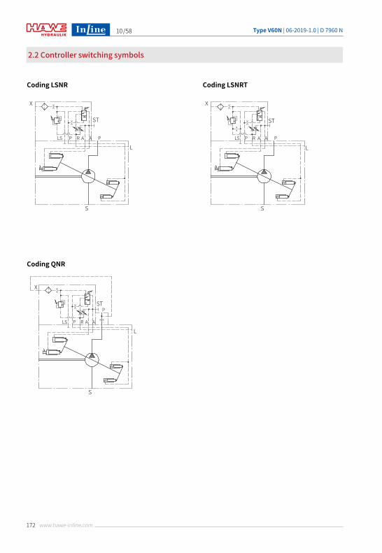
2.2 Controller switching symbols
Coding LSNR Coding LSNRT
Coding QNR
X
LS P R A A P
ST
L
S
X
LS P R A A P
ST
L
S
X
LS P R A A
PST
L
S
Type V60N | 06-2019-1.0 | D 7960 N /58
173www.hawe-inline.com
11
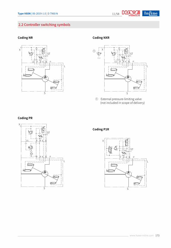
2.2 Controller switching symbols
Coding PR
Coding P1R
Coding NR Coding NXR
X
LS P R A A P
ST
L
S
X
LS P R A A
P R A A P
ST
L
S
X
P R A A P
ST
L
S
X①
LS P R A A P
ST
L
S
① External pressure-limiting valve (not included in scope of delivery)
Type V60N | 06-2019-1.0 | D 7960 N/58
174 www.hawe-inline.com
12
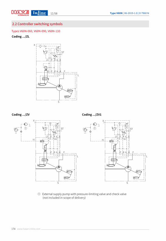
Coding .../ZL
Coding .../ZV Coding .../ZV1
X
LS
LS
P R A A
P R A A P
ST
L
S
X
LSX1
P R A A
P R A A P
ST
L
S
①
X
LSX1
P R A A
P R A A P
ST
L
S
①
① External supply pump with pressure-limiting valve and check valve (not included in scope of delivery)
2.2 Controller switching symbols
Types V60N-060, V60N-090, V60N-110
Type V60N | 06-2019-1.0 | D 7960 N /58
175www.hawe-inline.com
13
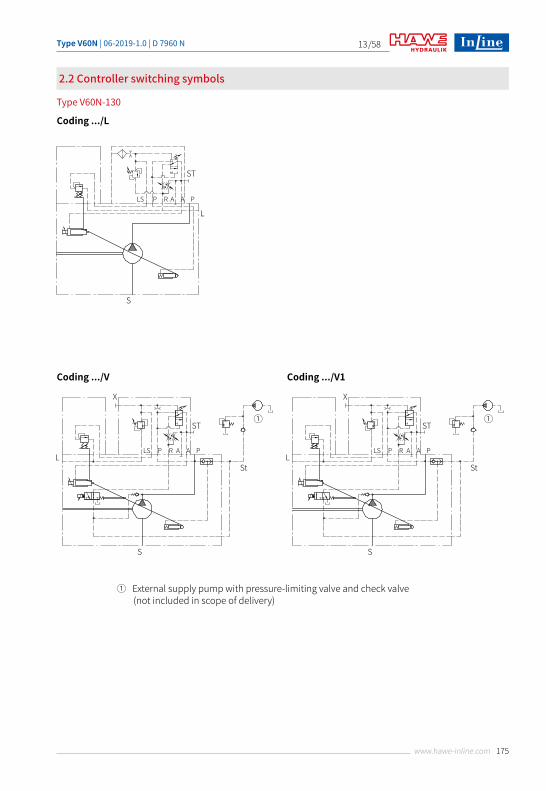
2.2 Controller switching symbols
Type V60N-130
Coding .../L
① External supply pump with pressure-limiting valve and check valve (not included in scope of delivery)
LS P R A A P
ST
L
S
Coding .../V
X
①
LS P R A A P
ST
LSt
S
Coding .../V1
X
①
LS P R A A P
ST
LSt
S
Type V60N | 06-2019-1.0 | D 7960 N/58
176 www.hawe-inline.com
14
Parameters
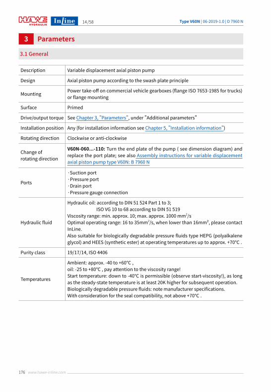
3.1 General
3
Description Variable displacement axial piston pump
Design Axial piston pump according to the swash plate principle
Mounting Power take-off on commercial vehicle gearboxes (flange ISO 7653-1985 for trucks) or flange mounting
Surface Primed
Drive/output torque See Chapter 3, "Parameters", under "Additional parameters"
Installation position Any (for installation information see Chapter 5, "Installation information")
Rotating direction Clockwise or anti-clockwise
Change of rotating direction
V60N-060...-110: Turn the end plate of the pump ( see dimension diagram) and replace the port plate; see also Assembly instructions for variable displacement axial piston pump type V60N: B 7960 N
Ports
·Suction port·Pressure port·Drain port·Pressure gauge connection
Hydraulic fluid
Hydraulic oil: according to DIN 51 524 Part 1 to 3; ISO VG 10 to 68 according to DIN 51 519Viscosity range: min. approx. 10; max. approx. 1000 mm2/sOptimal operating range: 16 to 35mm2/s, when lower than 16mm², please contact InLine.Also suitable for biologically degradable pressure fluids type HEPG (polyalkalene glycol) and HEES (synthetic ester) at operating temperatures up to approx. +70℃ .
Purity class 19/17/14, ISO 4406
Temperatures
Ambient: approx. -40 to +60℃ , oil: -25 to +80℃ , pay attention to the viscosity range!Start temperature: down to -40℃ is permissible (observe start-viscosity!), as long as the steady-state temperature is at least 20K higher for subsequent operation.Biologically degradable pressure fluids: note manufacturer specifications. With consideration for the seal compatibility, not above +70℃ .
Type V60N | 06-2019-1.0 | D 7960 N /58
177www.hawe-inline.com
15
3.1 General
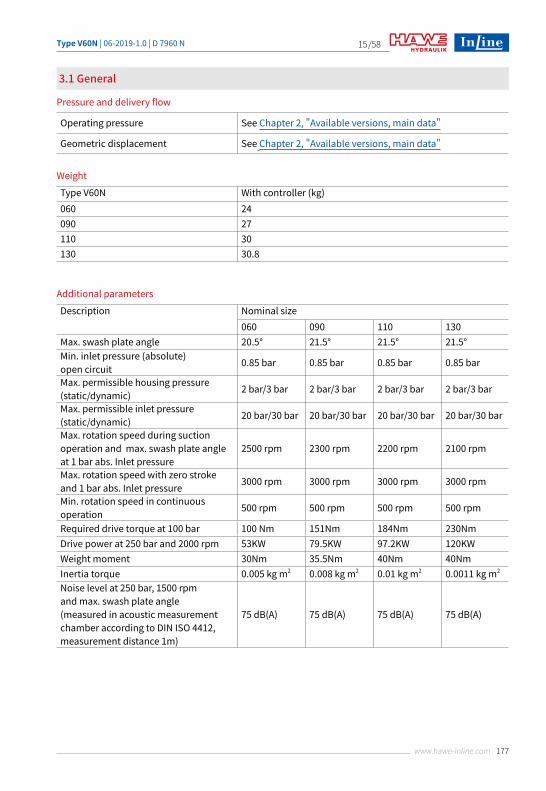
Pressure and delivery flow
Weight
Operating pressure See Chapter 2, "Available versions, main data"
Geometric displacement See Chapter 2, "Available versions, main data"
Additional parameters
Description Nominal size060 090 110 130
Max. swash plate angle 20.5° 21.5° 21.5° 21.5°Min. inlet pressure (absolute) open circuit 0.85 bar 0.85 bar 0.85 bar 0.85 bar
Max. permissible housing pressure (static/dynamic) 2 bar/3 bar 2 bar/3 bar 2 bar/3 bar 2 bar/3 bar
Max. permissible inlet pressure (static/dynamic) 20 bar/30 bar 20 bar/30 bar 20 bar/30 bar 20 bar/30 bar
Max. rotation speed during suctionoperation and max. swash plate angleat 1 bar abs. Inlet pressure
2500 rpm 2300 rpm 2200 rpm 2100 rpm
Max. rotation speed with zero stroke and 1 bar abs. Inlet pressure 3000 rpm 3000 rpm 3000 rpm 3000 rpm
Min. rotation speed in continuousoperation 500 rpm 500 rpm 500 rpm 500 rpm
Required drive torque at 100 bar 100 Nm 151Nm 184Nm 230NmDrive power at 250 bar and 2000 rpm 53KW 79.5KW 97.2KW 120KWWeight moment 30Nm 35.5Nm 40Nm 40NmInertia torque 0.005 kg m2 0.008 kg m2 0.01 kg m2 0.0011 kg m2
Noise level at 250 bar, 1500 rpmand max. swash plate angle(measured in acoustic measurementchamber according to DIN ISO 4412,measurement distance 1m)
75 dB(A) 75 dB(A) 75 dB(A) 75 dB(A)
Type V60N With controller (kg)060 24090 27110 30130 30.8
Type V60N | 06-2019-1.0 | D 7960 N/58
178 www.hawe-inline.com
16
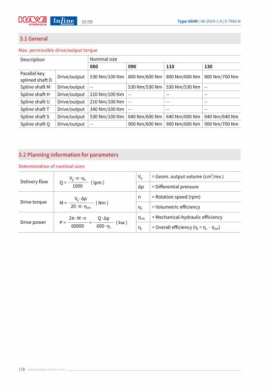
Delivery flowVg = Geom. output volume (cm3/rev.)
Δp = Differential pressure
Drive torquen = Rotation speed (rpm)
ηV = Volumetric efficiency
Drive powerηmh = Mechanical-hydraulic efficiency
ηt = Overall efficiency (ηt = ηv · ηmh)
3.1 General
3.2 Planning information for parameters
Max. permissible drive/output torque
Determination of nominal sizes
Description Nominal size060 090 110 130
Parallel key splined shaft D Drive/output 530 Nm/100 Nm 800 Nm/600 Nm 800 Nm/600 Nm 800 Nm/700 Nm
Spline shaft M Drive/output -- 530 Nm/530 Nm 530 Nm/530 Nm --Spline shaft H Drive/output 210 Nm/100 Nm -- -- --Spline shaft U Drive/output 210 Nm/100 Nm -- -- --Spline shaft T Drive/output 340 Nm/100 Nm -- -- --Spline shaft S Drive/output 530 Nm/100 Nm 640 Nm/600 Nm 640 Nm/600 Nm 640 Nm/640 NmSpline shaft Q Drive/output -- 900 Nm/600 Nm 900 Nm/600 Nm 900 Nm/700 Nm
Q = ————— ( lpm )
M = —————— ( Nm )
P = ————— = ————— ( kw )
Vg·n·ηV
1000
Vg·Δp20·π·ηmh
2π·M·n60000
Q·Δp600·ηt
Type V60N | 06-2019-1.0 | D 7960 N /58
179www.hawe-inline.com
17
200
①
②
③
180
160
140
120
100
80
60
40
20
0
200
-060
-090
-110
-130
-130
-110
-90
-60
180
160
140
120
100
80
60
40
20
00 100 200 300 400
Deliv
ery
flow
(lpm
)
Pressure (bar)
Pow
er (k
W)
Inle
t pre
sssu
re (b
ar)
Rotation speed (rpm)5000 1000 1500 2000 2500 3000 3500
( 0 bar relative = 1 bar absolute )
V60N
-130
V60N
-110
V60N
-090
V60N
-060
1.41.21
0.20.40.60.8
0-0.2
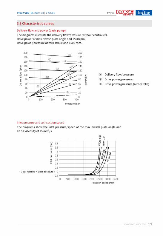
3.3 Characteristic curves
Delivery flow and power (basic pump)
Inlet pressure and self-suction speedThe diagrams show the inlet pressure/speed at the max. swash plate angle and an oil viscosity of 75 mm2/s
① Delivery flow/pressure② Drive power/pressure③ Drive power/pressure (zero stroke)
The diagrams illustrate the delivery flow/pressure (without controller).Drive power at max. swash plate angle and 1500 rpm.Drive power/pressure at zero stroke and 1500 rpm.
Type V60N | 06-2019-1.0 | D 7960 N/58
180 www.hawe-inline.com
18
3.4 Controller characteristic curves
t (ms)Pres
sure
(bar
)
pT1 TU SS
0,9TU T2
Approx. 5%
Operating pressure (bar)
Deliv
ery fl
ow Q
(%)
Operating pressure (bar)
Approx. 4 bar
Deliv
ery fl
ow Q
(%) 100
Deliv
ery
flow
Q (%
)
Pressure (bar)
Pressure / flow 100
100 200 300 400
50
0
Orifice diameter Ø (mm)
ΔP302520
300
250
200
150
100
50
0
Deliv
ery
flow
Q (%
)
4 83 6 10 10.52.5
T 1 Act
ing
time
(ms)
Pressure (bar)
100
100 200 300 4000
200
150
0
T 2 Act
ing
time
(ms)
Pressure (bar)
50
100 200 300 4000
150
100
0
Acting times T1 (LSNR controller) Acting times T2 (LSNR controller)
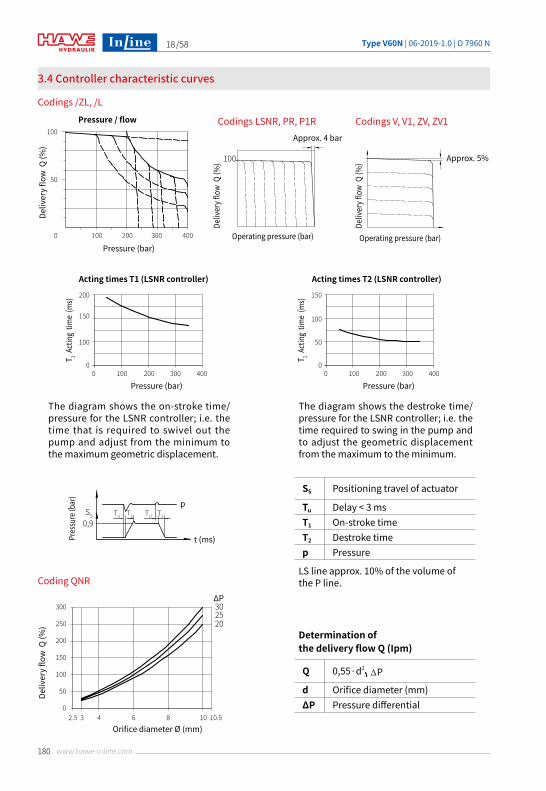
Q 0,55·d2
d Orifice diameter (mm)ΔP Pressure differential
SS Positioning travel of actuator
Tu Delay < 3 msT1 On-stroke timeT2 Destroke timep Pressure
3.4 Controller characteristic curves
Codings /ZL, /L
Coding QNR
Codings LSNR, PR, P1R Codings V, V1, ZV, ZV1
Determination of the delivery flow Q (Ipm)
The diagram shows the on-stroke time/pressure for the LSNR controller; i.e. the time that is required to swivel out the pump and adjust from the minimum to the maximum geometric displacement.
The diagram shows the destroke time/pressure for the LSNR controller; i.e. the time required to swing in the pump and to adjust the geometric displacement from the maximum to the minimum.
LS line approx. 10% of the volume of the P line.
PT
Type V60N | 06-2019-1.0 | D 7960 N /58
181www.hawe-inline.com
19
Pressure (bar)
(12 V)
(24 V)
400
25
Current (mA)
200 1200
100 600
Pressure (bar)
(12 V)
(24 V)
250
30
Current (mA)
300 1000
150 500
Delivery flow (%)
(12 V)
(24 V)
100
Current (mA)
600 2200
300 1100
Delivery flow (%)
(12 V)
(24 V)
100
Current (mA)
600 2200
300 1100
Delivery flow (%)
(12 V)
(24 V)
100
Current (mA)
300 700
150 350
Delivery flow (%)
(12 V)
(24 V)
100
Current (mA)
300 700
150 350
Codings PR
Codings V
Codings ZV
Codings P1R
Codings V1
Codings ZV1
3.4 Controller characteristic curves
Type V60N | 06-2019-1.0 | D 7960 N/58
182 www.hawe-inline.com
20
⑤
X
SP
115
②
①
③
④
B D
D
A
45.1
91.25
86 98.5
⑤
X
S P
115
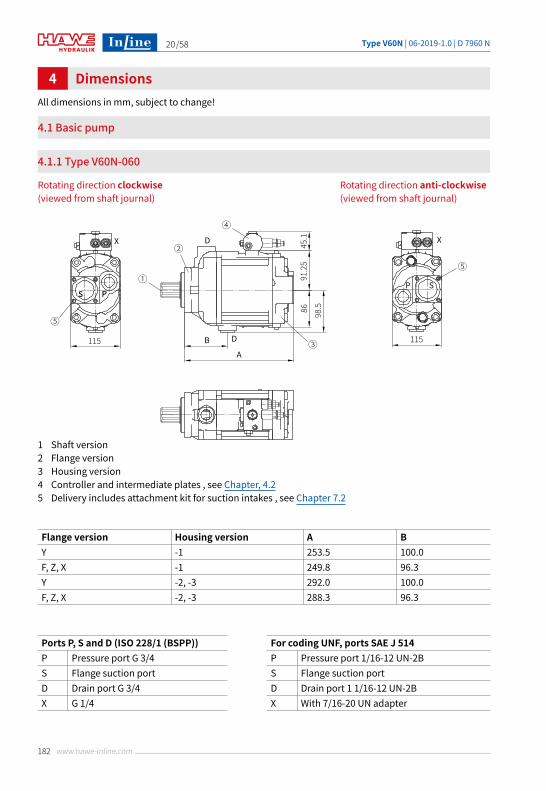
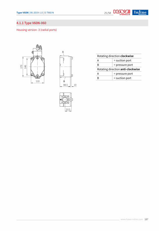
DimensionsAll dimensions in mm, subject to change!
4.1 Basic pump
4.1.1 Type V60N-060
4
Rotating direction clockwise (viewed from shaft journal)
Rotating direction anti-clockwise (viewed from shaft journal)
1 Shaft version2 Flange version3 Housing version4 Controller and intermediate plates , see Chapter, 4.25 Delivery includes attachment kit for suction intakes , see Chapter 7.2
Flange version Housing version A BY -1 253.5 100.0F, Z, X -1 249.8 96.3Y -2, -3 292.0 100.0F, Z, X -2, -3 288.3 96.3
Ports P, S and D (ISO 228/1 (BSPP)) For coding UNF, ports SAE J 514P Pressure port G 3/4 P Pressure port 1/16-12 UN-2BS Flange suction port S Flange suction portD Drain port G 3/4 D Drain port 1 1/16-12 UN-2BX G 1/4 X With 7/16-20 UN adapter
Type V60N | 06-2019-1.0 | D 7960 N /58
183www.hawe-inline.com
21
24
9
M12
55
9.6
46
9.6
41.2
9.6
34.7
28
12.7
M12
56.1
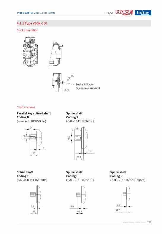
Stroke limitation (Vg approx. 4 cm3/rev.)
16
≤60
S P
4.1.1 Type V60N-060
Stroke limitation
Shaft versions
Parallel key splined shaftCoding D( similar to DIN ISO 14 )
Spline shaftCoding T( SAE-B-B 15T 16/32DP )
Spline shaftCoding S( SAE-C 14T 12/24DP )
Spline shaftCoding H( SAE-B 13T 16/32DP )
Spline shaftCoding U( SAE-B 13T 16/32DP short )
Type V60N | 06-2019-1.0 | D 7960 N/58
184 www.hawe-inline.com
22
Bleeding G1/8
Ø127
h8
102
71.312.7
Ø101
.6
102
71.3
89.8118
89.8
118
14
9.6
Ø80
Ø13
80
15
9 75
80
102
115
-0.0
3-0
.06
Ø101
.6
102
71.3
19
9.6
Bleeding G1/8
146
174
14
45°
114.5
140.5
114.
5
140.
5
14
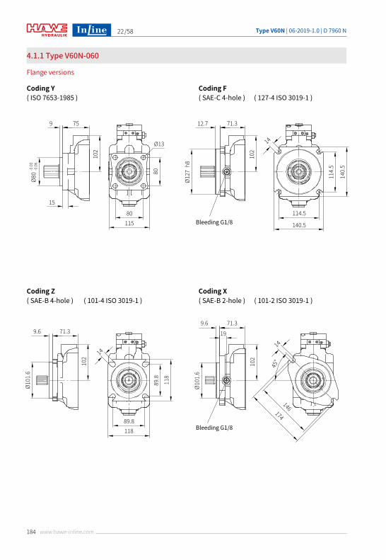
4.1.1 Type V60N-060
Flange versions
Coding Y( ISO 7653-1985 )
Coding Z( SAE-B 4-hole ) ( 101-4 ISO 3019-1 )
Coding F( SAE-C 4-hole ) ( 127-4 ISO 3019-1 )
Coding X( SAE-B 2-hole ) ( 101-2 ISO 3019-1 )
Type V60N | 06-2019-1.0 | D 7960 N /58
185www.hawe-inline.com
23
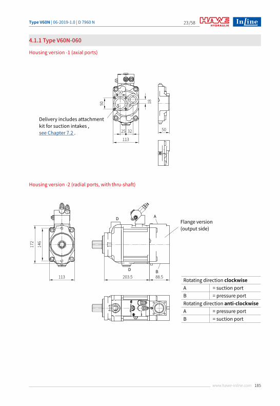
Delivery includes attachment kit for suction intakes , see Chapter 7.2 .
50
5025 32
113
S P50 18
113
172
146
203.5 88.5
D A
D B
Flange version (output side)
4.1.1 Type V60N-060
Housing version -1 (axial ports)
Housing version -2 (radial ports, with thru-shaft)
Rotating direction clockwise A = suction portB = pressure portRotating direction anti-clockwiseA = pressure portB = suction port
Type V60N | 06-2019-1.0 | D 7960 N/58
186 www.hawe-inline.com
24
2×M10depth 16
170
106.4130
34.4A
B 11
88.5
70.5
25
Ø82.
55
172
146
113
178
146
11889.8
89.8
42.8A
B 112288.5
67.5
Ø101
.6
Support 8×M8
Support 8×M8
Support 8×M8
43.4A
B 1388.5
45.5
Ø101
.6
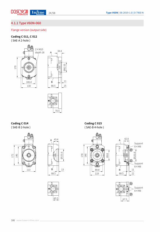
4.1.1 Type V60N-060
Flange version (output side)
Coding C 011, C 012( SAE-A 2-hole )
Coding C 014( SAE-B 2-hole )
Coding C 015( SAE-B 4-hole )
Type V60N | 06-2019-1.0 | D 7960 N /58
187www.hawe-inline.com
25
Rotating direction clockwise A = suction portB = pressure portRotating direction anti-clockwiseA = pressure portB = suction port
4.1.1 Type V60N-060
Housing version -3 (radial ports)
170
146
110
A
B88.5 10
53.5
Type V60N | 06-2019-1.0 | D 7960 N/58
188 www.hawe-inline.com
26
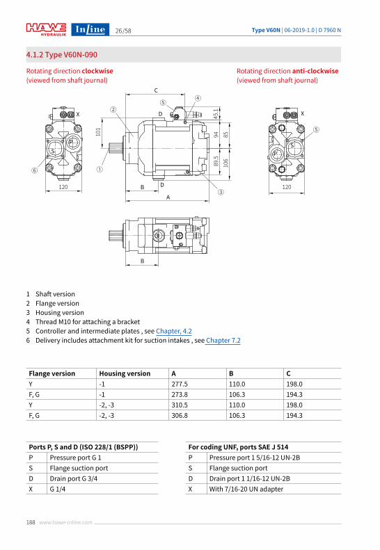
4.1.2 Type V60N-090
Rotating direction clockwise (viewed from shaft journal)
Rotating direction anti-clockwise (viewed from shaft journal)
1 Shaft version2 Flange version3 Housing version4 Thread M10 for attaching a bracket5 Controller and intermediate plates , see Chapter, 4.26 Delivery includes attachment kit for suction intakes , see Chapter 7.2
Flange version Housing version A B CY -1 277.5 110.0 198.0F, G -1 273.8 106.3 194.3Y -2, -3 310.5 110.0 198.0F, G -2, -3 306.8 106.3 194.3
Ports P, S and D (ISO 228/1 (BSPP)) For coding UNF, ports SAE J 514P Pressure port G 1 P Pressure port 1 5/16-12 UN-2BS Flange suction port S Flange suction portD Drain port G 3/4 D Drain port 1 1/16-12 UN-2BX G 1/4 X With 7/16-20 UN adapter
⑤
X
SP
120
②
①
③
④
B
B
D
D
C
A
45.1
94 85101
89.5
106
⑥
⑤X
SP
120
Type V60N | 06-2019-1.0 | D 7960 N /58
189www.hawe-inline.com
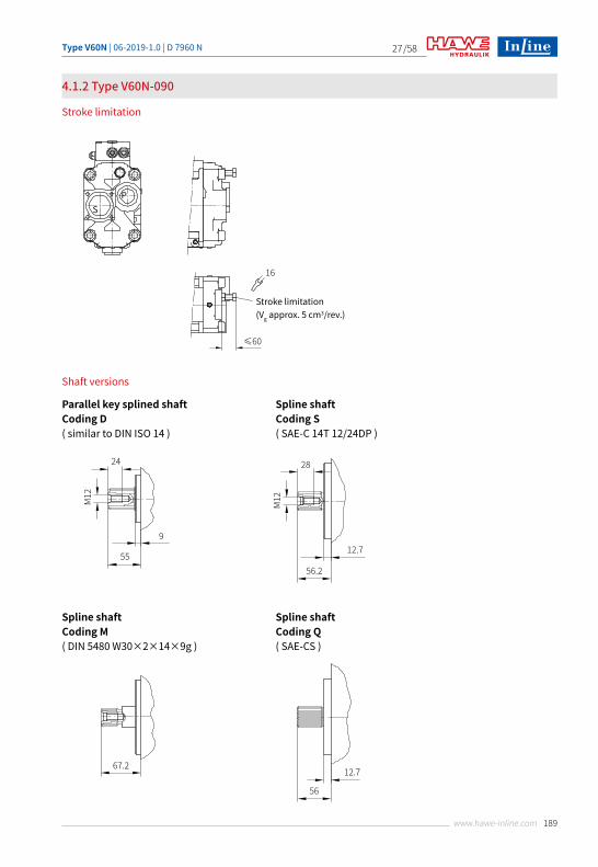
27
Stroke limitation (Vg approx. 5 cm3/rev.)
16
≤60
SP
12.7
56
67.2
24
9
M12
55
28
12.7
M12
56.2
4.1.2 Type V60N-090
Stroke limitation
Shaft versions
Parallel key splined shaftCoding D( similar to DIN ISO 14 )
Spline shaftCoding M( DIN 5480 W30×2×14×9g )
Spline shaftCoding S( SAE-C 14T 12/24DP )
Spline shaftCoding Q( SAE-CS )
Type V60N | 06-2019-1.0 | D 7960 N/58
190 www.hawe-inline.com
28
Ø127
h8
85.812.7
Ø80
Ø13
80
9 89.5
80
120
-0.0
3-0
.08
114.5
140.5
114.
5
140.
5
Ø14
Ø13.5
113.
2
140.
5
113.2
140.5
Ø125
9 85.8
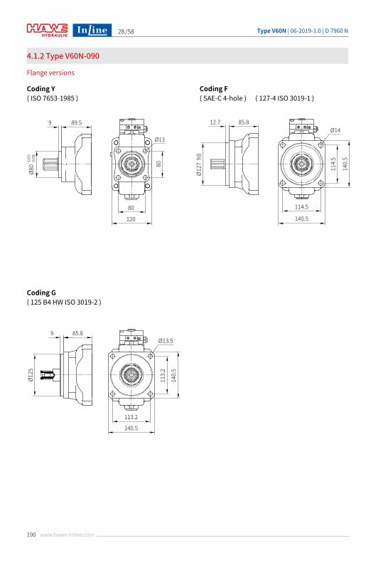
4.1.2 Type V60N-090
Flange versions
Coding Y( ISO 7653-1985 )
Coding G( 125 B4 HW ISO 3019-2 )
Coding F( SAE-C 4-hole ) ( 127-4 ISO 3019-1 )
Type V60N | 06-2019-1.0 | D 7960 N /58
191www.hawe-inline.com
29
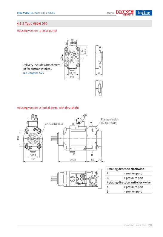
4.1.2 Type V60N-090
Housing version -1 (axial ports)
Housing version -2 (radial ports, with thru-shaft)
Delivery includes attachment kit for suction intakes , see Chapter 7.2 .
50
5528 32120
SP
50
20 90.5
106.4
2×M10 depth 15
150
120
222.5 88 25
D A
D B
Flange version (output side)
Rotating direction clockwise A = suction portB = pressure portRotating direction anti-clockwiseA = pressure portB = suction port
Type V60N | 06-2019-1.0 | D 7960 N/58
192 www.hawe-inline.com
30
2×M10depth 15
120
106.4150
42.9
Stroke limitation
A
B 1188
59
20
Ø101
.6
2×M12
120
146175
42.9
Stroke limitation
A
B 1188
39
Ø101
.6
4×M12depth 15
116
89.8
89.8120
34
Stroke limitation
A
B 11.5
88
64
25
Ø82.
55
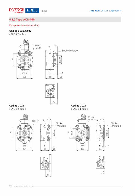
4.1.2 Type V60N-090
Flange version (output side)
Coding C 021, C 022( SAE-A 2-hole )
Coding C 024( SAE-B 2-hole )
Coding C 025( SAE-B 4-hole )
Type V60N | 06-2019-1.0 | D 7960 N /58
193www.hawe-inline.com
31
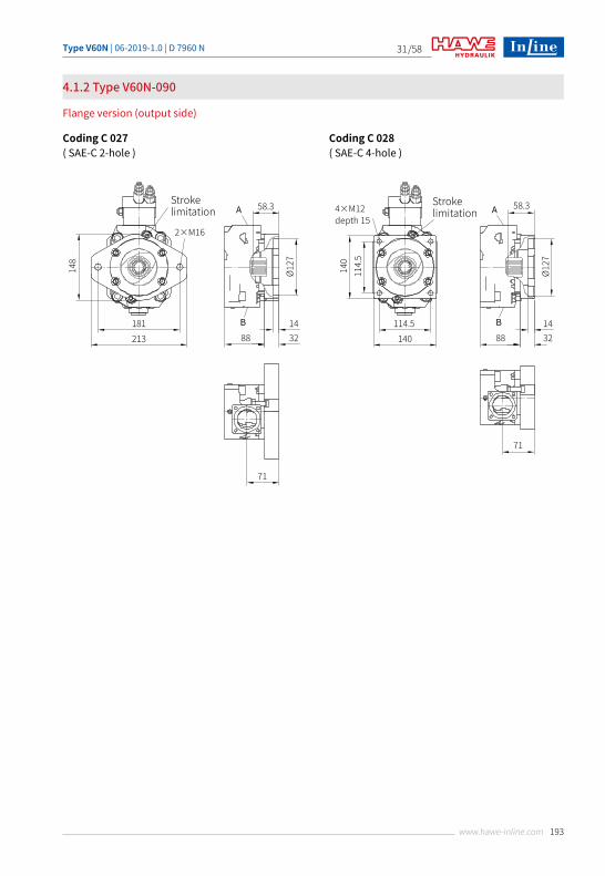
4.1.2 Type V60N-090
Flange version (output side)
Coding C 027( SAE-C 2-hole )
Coding C 028( SAE-C 4-hole )
58.3A
B 1488
71
32
Ø127
2×M16
148
181213
Stroke limitation 58.3A
B 1488
71
32
Ø127
4×M12depth 15
140
114.
5
114.5140
Stroke limitation
Type V60N | 06-2019-1.0 | D 7960 N/58
194 www.hawe-inline.com
32
A
B1288
51
117.8
89.8
89.8117.8
130 3
18
31.1 46.5
M12×2
42.9
77.8
23.8
50.8
M10×2.1
55
95
S P
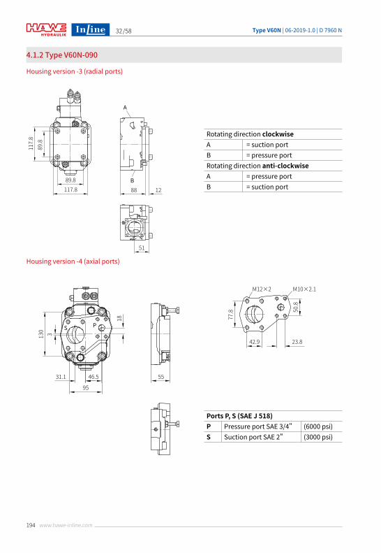
Rotating direction clockwise A = suction portB = pressure portRotating direction anti-clockwiseA = pressure portB = suction port
Ports P, S (SAE J 518)P Pressure port SAE 3/4" (6000 psi)S Suction port SAE 2" (3000 psi)
4.1.2 Type V60N-090
Housing version -3 (radial ports)
Housing version -4 (axial ports)
Type V60N | 06-2019-1.0 | D 7960 N /58
195www.hawe-inline.com
33
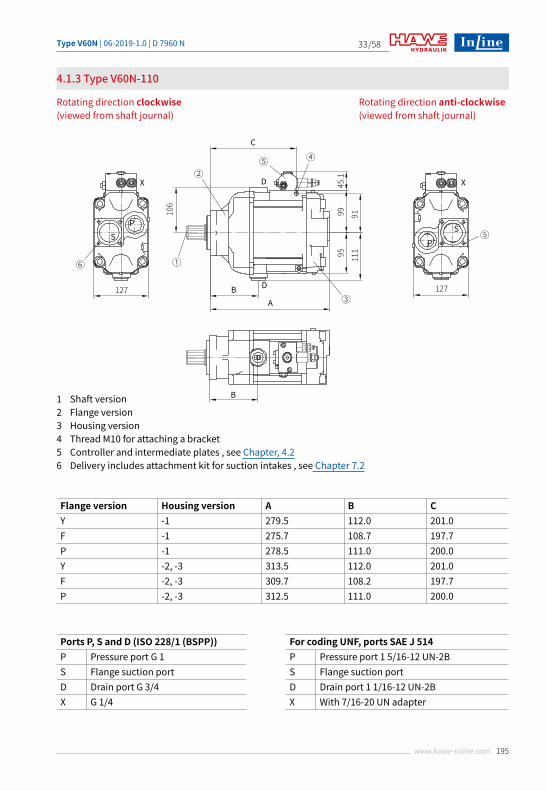
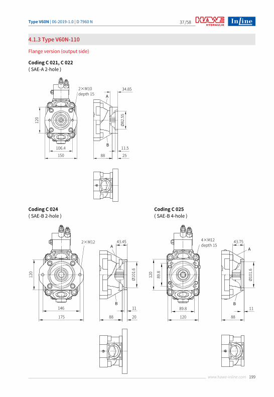
4.1.3 Type V60N-110
Rotating direction clockwise (viewed from shaft journal)
Rotating direction anti-clockwise (viewed from shaft journal)
1 Shaft version2 Flange version3 Housing version4 Thread M10 for attaching a bracket5 Controller and intermediate plates , see Chapter, 4.26 Delivery includes attachment kit for suction intakes , see Chapter 7.2
Flange version Housing version A B CY -1 279.5 112.0 201.0F -1 275.7 108.7 197.7P -1 278.5 111.0 200.0Y -2, -3 313.5 112.0 201.0F -2, -3 309.7 108.2 197.7P -2, -3 312.5 111.0 200.0
Ports P, S and D (ISO 228/1 (BSPP)) For coding UNF, ports SAE J 514P Pressure port G 1 P Pressure port 1 5/16-12 UN-2BS Flange suction port S Flange suction portD Drain port G 3/4 D Drain port 1 1/16-12 UN-2BX G 1/4 X With 7/16-20 UN adapter
⑤
X
SP
127
②
①
③
④
B
B
D
D
C
A
45.1
99 91106
95 111
⑥
⑤
X
SP
127
Type V60N | 06-2019-1.0 | D 7960 N/58
196 www.hawe-inline.com
34
Stroke limitation (Vg approx. 6 cm3/rev.)
16
≤60
12.7
56
67.2
24
9
M12
54.85
28
12.7
M12
56.05
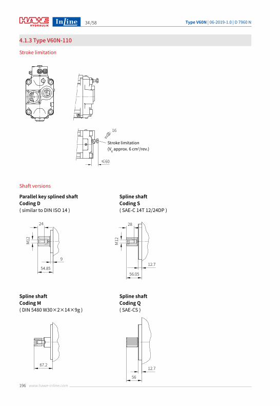
4.1.3 Type V60N-110
Stroke limitation
Shaft versions
Parallel key splined shaftCoding D( similar to DIN ISO 14 )
Spline shaftCoding M( DIN 5480 W30×2×14×9g )
Spline shaftCoding S( SAE-C 14T 12/24DP )
Spline shaftCoding Q( SAE-CS )
Type V60N | 06-2019-1.0 | D 7960 N /58
197www.hawe-inline.com
35
Ø127
h8
87.712.7
Ø80
Ø13
80
9 91.5
80
127
-0.0
3-0
.06
114.5
140.5
114.
514
0.5
Ø14
Ø80
55°
80
80
9 90.5
-0.0
3-0
.06
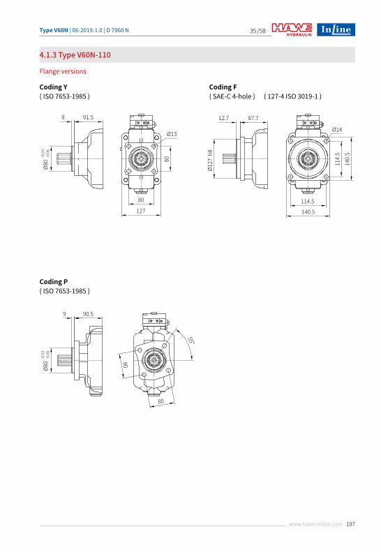
4.1.3 Type V60N-110
Flange versions
Coding Y( ISO 7653-1985 )
Coding P( ISO 7653-1985 )
Coding F( SAE-C 4-hole ) ( 127-4 ISO 3019-1 )
Type V60N | 06-2019-1.0 | D 7960 N/58
198 www.hawe-inline.com
36
Delivery includes attachment kit for suction intakes , see Chapter 7.2 .
50
5427.35 32
127
SP
50
18
89.8
4×M12 depth 15
120
120
89.8
222.5 88
DA
D B
Flange version (output side)
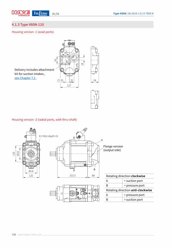
Housing version -1 (axial ports)
Housing version -2 (radial ports, with thru-shaft)
Rotating direction clockwise A = suction portB = pressure portRotating direction anti-clockwiseA = pressure portB = suction port
4.1.3 Type V60N-110
Type V60N | 06-2019-1.0 | D 7960 N /58
199www.hawe-inline.com
37
2×M10depth 15
120
106.4150
34.85A
B11.5
88 25
Ø82.
55
43.45A
B11
88 20
Ø101
.6
2×M12
120
146
175
43.75
A
B11
88
Ø101
.6
4×M12depth 15
120
89.8
89.8
120
4.1.3 Type V60N-110
Flange version (output side)
Coding C 021, C 022( SAE-A 2-hole )
Coding C 024( SAE-B 2-hole )
Coding C 025( SAE-B 4-hole )
Type V60N | 06-2019-1.0 | D 7960 N/58
200 www.hawe-inline.com
38
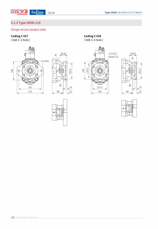
4.1.3 Type V60N-110
Flange version (output side)
Coding C 027( SAE-C 2-hole )
Coding C 028( SAE-C 4-hole )
58.85A
B14
88 32
Ø127
2×M16
148
181
213
4×M12depth 15
140
114.
5114.5
140
58.85
A
B14
88 32
Ø127
Type V60N | 06-2019-1.0 | D 7960 N /58
201www.hawe-inline.com
39
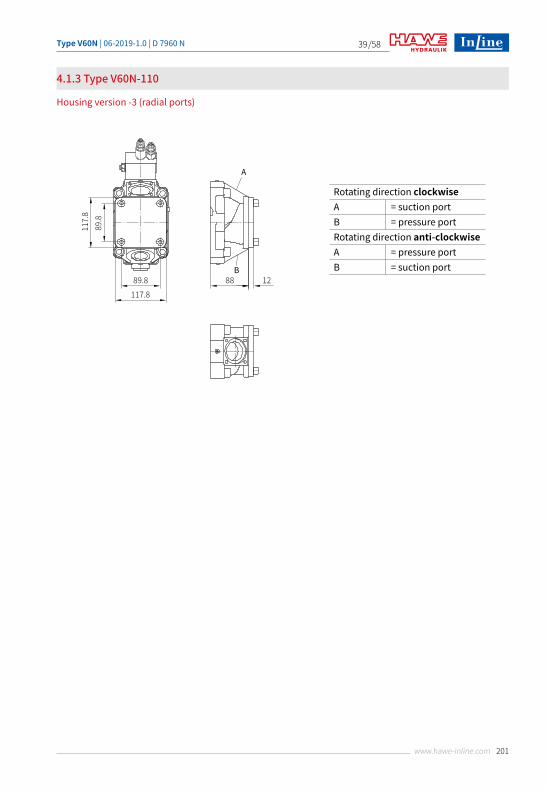
Rotating direction clockwise A = suction portB = pressure portRotating direction anti-clockwiseA = pressure portB = suction port
4.1.3 Type V60N-110
Housing version -3 (radial ports)
A
B1288
117.8
89.8
89.8117.8
Type V60N | 06-2019-1.0 | D 7960 N/58
202 www.hawe-inline.com
40
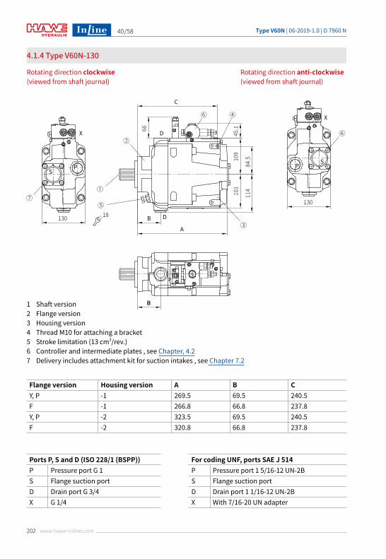
4.1.4 Type V60N-130
Rotating direction clockwise (viewed from shaft journal)
Rotating direction anti-clockwise (viewed from shaft journal)
1 Shaft version2 Flange version3 Housing version4 Thread M10 for attaching a bracket5 Stroke limitation (13 cm3/rev.)6 Controller and intermediate plates , see Chapter, 4.27 Delivery includes attachment kit for suction intakes , see Chapter 7.2
Flange version Housing version A B CY, P -1 269.5 69.5 240.5F -1 266.8 66.8 237.8Y, P -2 323.5 69.5 240.5F -2 320.8 66.8 237.8
Ports P, S and D (ISO 228/1 (BSPP)) For coding UNF, ports SAE J 514P Pressure port G 1 P Pressure port 1 5/16-12 UN-2BS Flange suction port S Flange suction portD Drain port G 3/4 D Drain port 1 1/16-12 UN-2BX G 1/4 X With 7/16-20 UN adapter
⑥
X
SP
130
②
①
⑤
③
④⑥
B
B
D
D
C
A45.1
109
66
84.5
101
114
⑦
X
SP
130 18
Type V60N | 06-2019-1.0 | D 7960 N /58
203www.hawe-inline.com
41
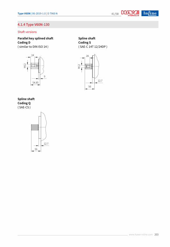
4.1.4 Type V60N-130
Shaft versions
Parallel key splined shaftCoding D( similar to DIN ISO 14 )
Spline shaftCoding S( SAE-C 14T 12/24DP )
Spline shaftCoding Q( SAE-CS )
24
9
M12
54.85
28
12.7M12
56
12.7
56
Type V60N | 06-2019-1.0 | D 7960 N/58
204 www.hawe-inline.com
42Ø8
0
109
Ø13
80
9 90.5
80
130
-0.0
3-0
.06
114.5
140.5
114.
5
Ø14
Ø127
h8
87.8
109
12.7
Ø80
55°
80
80
9 90.5
55
-0.0
3-0
.06
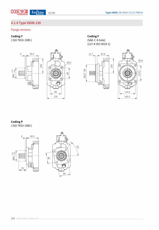
4.1.4 Type V60N-130
Flange versions
Coding Y( ISO 7653-1985 )
Coding F(SAE-C 4-hole) (127-4 ISO 3019-1)
Coding P( ISO 7653-1985 )
Type V60N | 06-2019-1.0 | D 7960 N /58
205www.hawe-inline.com
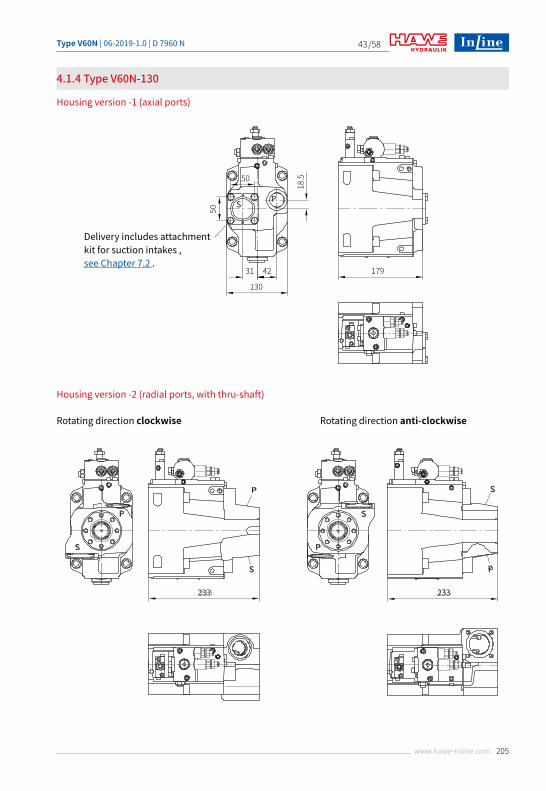
43
Delivery includes attachment kit for suction intakes , see Chapter 7.2 .
50
17931 42
130
S P50
18.5
S
P
S
S
P
P
233
S
P
233
Housing version -1 (axial ports)
Housing version -2 (radial ports, with thru-shaft)
4.1.4 Type V60N-130
Rotating direction clockwise Rotating direction anti-clockwise
Type V60N | 06-2019-1.0 | D 7960 N/58
206 www.hawe-inline.com
44
□ 11080
M10
M12
6.5
23
80 53
94
M8
9
18
106.
4
Ø13074
120
M8
M12
11.5
23
146
Ø170
89.8
M12
M8
6.5
23
89.8
89.8
66
□ 120
M12
M8
13
25
114.
5
114.5
90
□ 140
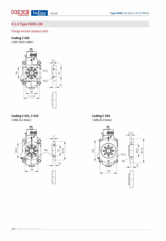
4.1.4 Type V60N-130
Flange version (output side)
Coding C 030( ISO 7653-1985 )
Coding C 031, C 032( SAE-A 2-hole )
Coding C 034( SAE-B 2-hole )
Type V60N | 06-2019-1.0 | D 7960 N /58
207www.hawe-inline.com
45
□ 11080
M10
M12
6.5
23
80 53
94
M8
9
18
106.
4
Ø13074
120
M8
M12
11.5
23
146
Ø170
89.8
M12
M8
6.5
23
89.8
89.8
66
□ 120
M12
M8
13
25
114.
5
114.5
90
□ 140
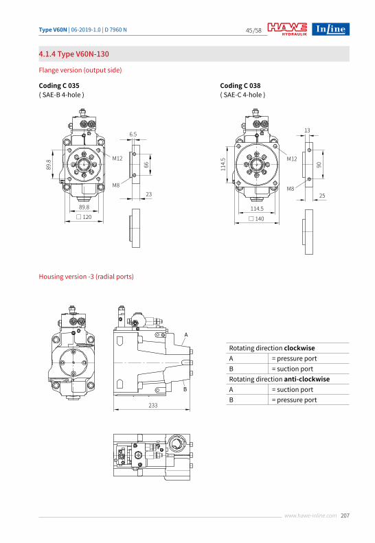
4.1.4 Type V60N-130
Flange version (output side)
Coding C 035( SAE-B 4-hole )
Coding C 038( SAE-C 4-hole )
Rotating direction clockwise A = pressure portB = suction portRotating direction anti-clockwiseA = suction portB = pressure port
Housing version -3 (radial ports)
A
B
233
Type V60N | 06-2019-1.0 | D 7960 N/58
208 www.hawe-inline.com
46
84 1720Nm
②
②
③
①
1720Nm
6
≈96
≈105
72
4
29.4 45.1X
M6 13Nm
①
845.8
1720Nm
1720Nm
6
≈96
≈105
72
4
29.4 45.1X
M6 13Nm
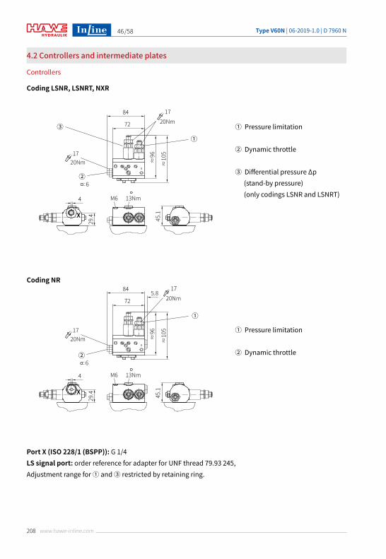
4.2 Controllers and intermediate plates
Controllers
Coding LSNR, LSNRT, NXR
Coding NR
Port X (ISO 228/1 (BSPP)): G 1/4LS signal port: order reference for adapter for UNF thread 79.93 245, Adjustment range for ① and ③ restricted by retaining ring.
① Pressure limitation
② Dynamic throttle
③ Differential pressure Δp (stand-by pressure) (only codings LSNR and LSNRT)
① Pressure limitation
② Dynamic throttle
Type V60N | 06-2019-1.0 | D 7960 N /58
209www.hawe-inline.com
47
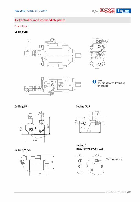
4.2 Controllers and intermediate plates
Controllers
Coding QNR
57.5 88.5
≈99
45.1 46
≈106
55
70
19 43.5
≈66
Torque setting
Note: The piping varies depending on the size.
Coding /PR Coding /P1R
Coding /V, /V1
Coding /L (only for type V60N-130)
Type V60N | 06-2019-1.0 | D 7960 N/58
210 www.hawe-inline.com
48
28 78
≈74
Torque setting
49.5 79.5
100.5
≈62
≈64 ≈96
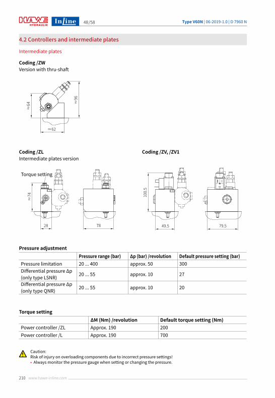
4.2 Controllers and intermediate plates
Intermediate plates
Coding /ZWVersion with thru-shaft
Coding /ZLIntermediate plates version
Coding /ZV, /ZV1
Pressure adjustmentPressure range (bar) Δp (bar) /revolution Default pressure setting (bar)
Pressure limitation 20 ... 400 approx. 50 300Differential pressure Δp(only type LSNR) 20 ... 55 approx. 10 27
Differential pressure Δp(only type QNR) 20 ... 55 approx. 10 20
Torque settingΔM (Nm) /revolution Default torque setting (Nm)
Power controller /ZL Approx. 190 200Power controller /L Approx. 190 700
Caution:Risk of injury on overloading components due to incorrect pressure settings!• Always monitor the pressure gauge when setting or changing the pressure.
Type V60N | 06-2019-1.0 | D 7960 N /58
211www.hawe-inline.com
49
Installation information
5.1 General information
5
The V60N variable displacement axial piston pump is designed for use in an open circuit.It can be mounted directly on a truck power take-off (PTO) using a flange in accordance with ISO 7653-1985 or using a flange in accordance with specifications.Further connection options are available with a propshaft and suitable coupling sleeves ( see Chapter 7, "Accessories, spare parts and separate components")A change of rotating direction is available for types V60N-060, V60N-090 and V60N-110 variable displacement axial piston pumps. For conversion instructions, please contact InLine Hydraulik GmbH.
The following essential points must be noted when installing the pump:Mounting and removal of the pump and attached components may be performed by trained persons only. Ensure absolute cleanliness during all work. Contamination may have an adverse effect on the function and lifetime of the pump.
• Remove all plastic plugs prior to initial operation.• Avoid installing the motor above the tank ( see Chapter 5.3, "Installation positions").• Observe the reference values in Chapter 7.2, "Suction intakes".• Prior to initial operation, fill the pump with oil and bleed. Automatic pump filling via the suction line by opening the drain ports is not possible.• Prevent the pump and suction line from running dry.• Always ensure a constant supply of oil. Even a brief shortage in the supply of hydraulic fluid to the pump may damage internal parts. This may not be immediately evident after initial operation.• The hydraulic oil returning to the tank from the system must not be sucked back in immediately (baffles).• Run the pump for approx. 10 minutes at max. 50 bar after initial operation.• Thorough bleeding/flushing of the entire system is recommended before the full pressure range is used.• Observe the max. permissible operating range temperatures ( see Chapter 3, "Parameters") at all times.• Always comply with the specified oil purity classes ( see Chapter 3, "Parameters"); provide appropriate hydraulic fluid filtering.• Use of a filter in the suction line must be approved by InLine Hydraulik.• Include a main pressure-limiting valve in the pressure line to limit the max. system pressure.
Type V60N | 06-2019-1.0 | D 7960 N/58
212 www.hawe-inline.com
50
5.2 Ports
The nominal diameter of the connecting lines depends on the specified operating conditions, the viscosity of the hydraulic fluid, the start-up and operating temperatures and the rotation speed of the pump. In principle we recommend the use of hose lines due to the superior damping characteristics.
Pressure portThe pressure port connection on type V60N-060 is established via a threaded connection G 3/4" (BSPP); on type V60N-090/110/130 via a threaded connection G 1" (BSPP).Observe the tightening torque specified by the fitting manufacturer.
Suction portThe suction port on all pumps is established via standardised suction intakes with a size that is dependent on the max. delivery flow of the pump.The specifications of the max. delivery flow Qmax must be observed. These can be found in the following table.
The suction intakes can be ordered as an option with the pump.If possible, route the suction line to the tank in such a way that it is steadily rising. This allows trapped air to escape. Observe the specifications in Chapter 5, "Installation information". The absolute suction pressure must not fall below 0.85bar. A hose line should generally be used in preference to a rigid pipe.
Drain portThe V60N pumps have 2 drain ports G 3/4" (BSPP) or 1 1/16-12-UN-2B. A G 1/8" (BSPP) threaded connection is also available for the flange version SAE-B2, SAE-B4 and SAE-4. This is used for bleeding in the case of vertical installation positions.The nominal diameter of the leakage line must not be less than 16 mm. The cross-section is determined by the max. permissible housing pressure.Integrate the leakage line in the system in such a way as to prevent direct connection with the suction line of the pump. Both drain ports can be used simultaneously.A separate leakage line from the controller to the tank is not required. Observe the specifications in Chapter 5.3, "Installation positions".
LS port for version LSNR, LSNRT, NXRThe LS line is connected to the controller via a G 1/4" (BSPP) threaded connection.The nominal diameter of the line depends on the installation position of the pump and should be 10% of the pressure line nominal volume. A hose line should generally be used in preference to a rigid pipe.
• When the prop ortional directional spool valve is in a neutral position, the LS line must be fully relieved (only controller type LSNR, LSN). In the case of controller type LSNRT, relief takes place internally in the controller.
Nominal width (N) 38 (1 1/2") 42 50 (2") 64 (2 1/2") 74 (3") 6 (G 1 1/4) 7 (G 1 1/2)Qmax (lpm) 75 90 125 190 250 90 125
Type V60N | 06-2019-1.0 | D 7960 N /58
213www.hawe-inline.com
51
5.3 Installation positions
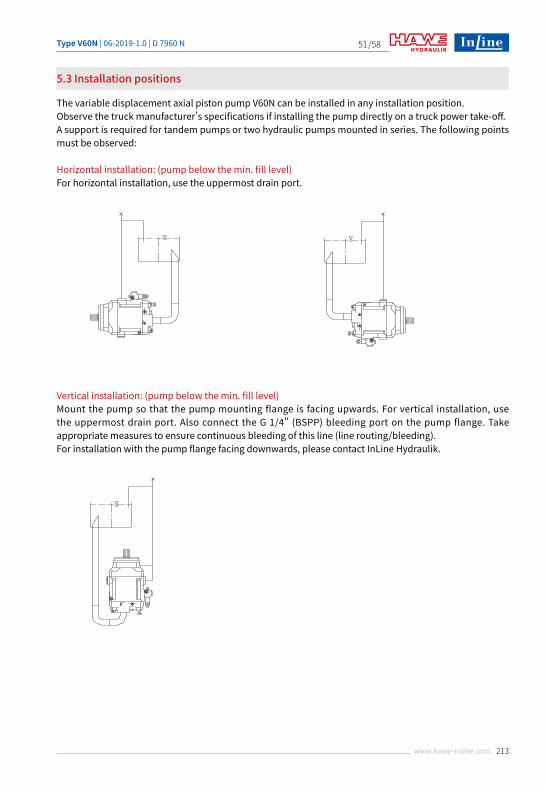
The variable displacement axial piston pump V60N can be installed in any installation position.Observe the truck manufacturer's specifications if installing the pump directly on a truck power take-off.A support is required for tandem pumps or two hydraulic pumps mounted in series. The following points must be observed:
Horizontal installation: (pump below the min. fill level)For horizontal installation, use the uppermost drain port.
Vertical installation: (pump below the min. fill level)Mount the pump so that the pump mounting flange is facing upwards. For vertical installation, use the uppermost drain port. Also connect the G 1/4" (BSPP) bleeding port on the pump flange. Take appropriate measures to ensure continuous bleeding of this line (line routing/bleeding).For installation with the pump flange facing downwards, please contact InLine Hydraulik.
Type V60N | 06-2019-1.0 | D 7960 N/58
214 www.hawe-inline.com
52
Z05
h≤800
Z05
Z05
5.4 Tank installation
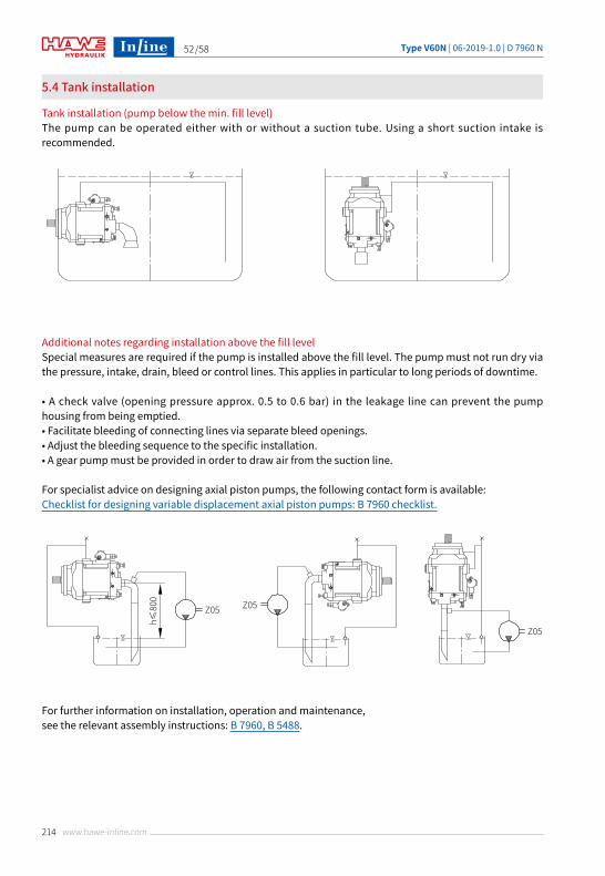
Tank installation (pump below the min. fill level)The pump can be operated either with or without a suction tube. Using a short suction intake is recommended.
Additional notes regarding installation above the fill levelSpecial measures are required if the pump is installed above the fill level. The pump must not run dry via the pressure, intake, drain, bleed or control lines. This applies in particular to long periods of downtime.
• A check valve (opening pressure approx. 0.5 to 0.6 bar) in the leakage line can prevent the pump housing from being emptied.• Facilitate bleeding of connecting lines via separate bleed openings.• Adjust the bleeding sequence to the specific installation.• A gear pump must be provided in order to draw air from the suction line.
For specialist advice on designing axial piston pumps, the following contact form is available:Checklist for designing variable displacement axial piston pumps: B 7960 checklist.
For further information on installation, operation and maintenance, see the relevant assembly instructions: B 7960, B 5488.
Type V60N | 06-2019-1.0 | D 7960 N /58
215www.hawe-inline.com
53
Installation, operation and maintenance information
6.1 Designated use
6.3 Operating instructions
6.2 Assembly information
6
This fluid-power product has been designed, manufactured and tested using standards and regulations generally applicable in the European Union and left the plant in a safe and fault-free condition.To maintain this condition and ensure safe operation, operators must observe the information and warnings in this documentation.This fluid-power product must be installed and integrated in a hydraulic system by a qualified specialist who is familiar with and adheres to general engineering principles and relevant applicable regulations and standards.In addition, application-specific features of the system or installation location must be taken into account if relevant.This product may only be used as a pump within oil-hydraulic systems.The product must be operated within the specified technical parameters. This documentation contains the technical parameters for various product versions.
The hydraulic accumulator must be integrated in the system via state of the art connection components ( screw fittings, hoses, pipes, etc. ). The hydraulic system must be shut down as a precautionary measure prior to dismounting; this applies in particular to systems with hydraulic accumulators.
Note: Non-compliance will void any warranty claims made against InLine Hydraulik.
Product, pressure and/or flow settingsAll statements in this documentation must be observed for all product, pressure and/or flow settings on or in the hydraulic system.
Filtering and purity of the hydraulic fluidSoiling in the fine range, e.g. abraded material and dust, or in the macro range, e.g. chips, rubber particles from hoses and seals, can cause significant malfunctions in a hydraulic system. It is also to be noted that new hydraulic fluid "from the drum" does not necessarily meet the highest purity requirements.For trouble-free operation pay attention to the purity of the hydraulic fluid ( see also purity class in Chapter 3, "Parameters" ).
For further information on installation, operation and maintenance, see the relevant assembly instructions: B 7960, B 5488.
Caution:Risk of injury on overloading components due to incorrect pressure settings!• Always monitor the pressure gauge when setting or changing the pressure.
Type V60N | 06-2019-1.0 | D 7960 N/58
216 www.hawe-inline.com
54
Coding LSN Coding LLSN
Coding N Coding LN
①
⑤
LS
L S
d1 d4
(d2 )d3
d6
P
②③④
Power controllerLS
L S
P
X
L S
(d4 )
d2(d3 )
d6 d8
P X
L S
P
Accessories, spare parts and separate components
7.1 Discontinued controller units
7.1.1 Available versions
7
Controller
Switching symbols
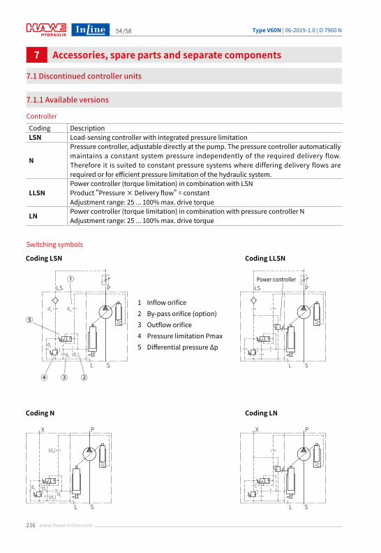
Coding DescriptionLSN Load-sensing controller with integrated pressure limitation
N
Pressure controller, adjustable directly at the pump. The pressure controller automatically maintains a constant system pressure independently of the required delivery flow. Therefore it is suited to constant pressure systems where differing delivery flows are required or for efficient pressure limitation of the hydraulic system.
LLSNPower controller (torque limitation) in combination with LSNProduct "Pressure × Delivery flow" = constantAdjustment range: 25 ... 100% max. drive torque
LN Power controller (torque limitation) in combination with pressure controller NAdjustment range: 25 ... 100% max. drive torque
1 Inflow orifice2 By-pass orifice (option)3 Outflow orifice4 Pressure limitation Pmax5 Differential pressure Δp
Type V60N | 06-2019-1.0 | D 7960 N /58
217www.hawe-inline.com
55
Pressure differential Δp (only controller LSN and LLSN)
Power setting
7413
8 22
LS(X) 37
.5
≈91
Pressure limitation
34
19
48 13
A00/... 45/... A90/... A7
h6.2
h 6.2
kh
6.2
Nh6.2
Nk
N
N
45°
7.1.1 Available versions
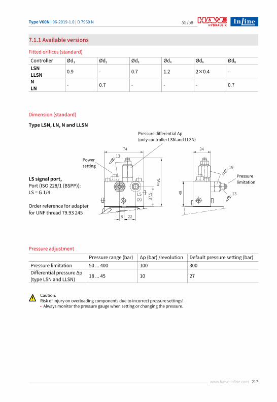
Fitted orifices (standard)
Pressure adjustment
Dimension (standard)
Controller Ød1 Ød2 Ød3 Ød4 Ød6 Ød8
LSNLLSN 0.9 - 0.7 1.2 2×0.4 -
NLN - 0.7 - - - 0.7
Pressure range (bar) Δp (bar) /revolution Default pressure setting (bar)Pressure limitation 50 ... 400 100 300Differential pressure Δp(type LSN and LLSN) 18 ... 45 10 27
LS signal port, Port (ISO 228/1 (BSPP)): LS = G 1/4
Order reference for adapter for UNF thread 79.93 245
Type LSN, LN, N and LLSN
Caution:Risk of injury on overloading components due to incorrect pressure settings!• Always monitor the pressure gauge when setting or changing the pressure.
Type V60N | 06-2019-1.0 | D 7960 N/58
218 www.hawe-inline.com
56
7.2 Suction intakes
Order coding example:
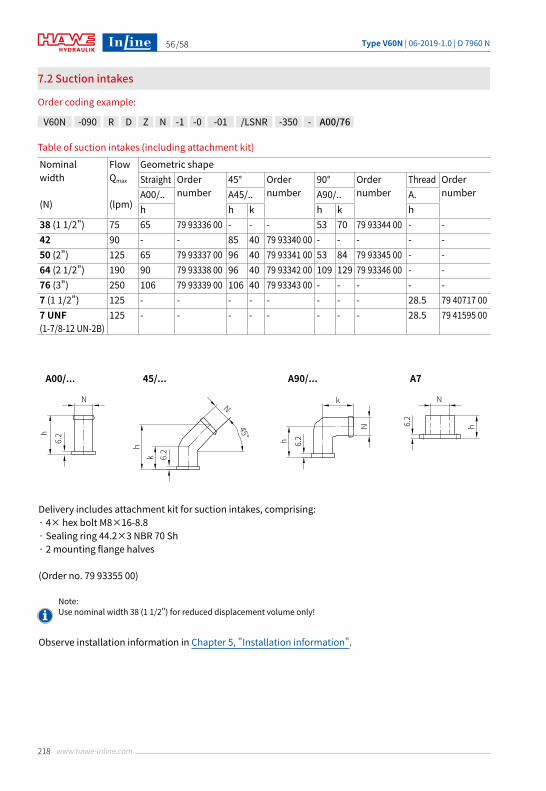
Table of suction intakes (including attachment kit)
Note: Use nominal width 38 (1 1/2") for reduced displacement volume only!
Nominal width
(N)
Flow Qmax
(lpm)
Geometric shapeStraight Order
number45° Order
number90° Order
numberThread Order
numberA00/.. A45/.. A90/.. A.h h k h k h
38 (1 1/2") 75 65 79 93336 00 - - - 53 70 79 93344 00 - -42 90 - - 85 40 79 93340 00 - - - - -50 (2") 125 65 79 93337 00 96 40 79 93341 00 53 84 79 93345 00 - -64 (2 1/2") 190 90 79 93338 00 96 40 79 93342 00 109 129 79 93346 00 - -76 (3") 250 106 79 93339 00 106 40 79 93343 00 - - - - -7 (1 1/2") 125 - - - - - - - - 28.5 79 40717 007 UNF (1-7/8-12 UN-2B)
125 - - - - - - - - 28.5 79 41595 00
V60N -090 R D Z N -1 -0 -01 /LSNR -350 - A00/76
Delivery includes attachment kit for suction intakes, comprising:· 4× hex bolt M8×16-8.8· Sealing ring 44.2×3 NBR 70 Sh· 2 mounting flange halves
(Order no. 79 93355 00)
Observe installation information in Chapter 5, "Installation information".
Pressure differential Δp (only controller LSN and LLSN)
Power setting
7413
8 22
LS(X) 37
.5
≈91
Pressure limitation
34
19
48 13
A00/... 45/... A90/... A7
h6.2
h 6.2
kh
6.2
N
h6.2
Nk
N
N
45°
Type V60N | 06-2019-1.0 | D 7960 N /58
219www.hawe-inline.com
57
Coding SAE-C, SAE-CS
Coding SAE-C, SAE-CS, DIN ISO 014
2 56
Ø100
Ø8
Ø84±0.1Ø5
7 h
7
Ø60
Coding DIN ISO 014
2 53
Ø100
Ø8
Ø84±0.1
Ø57
h7
Ø60
2119
9
6×M8 depth 16.5
48 20° 20°
54
120Nm
Ø9
Ø100
Ø14
Ø57
f7
TK Ø
84 (6
×60
°)
Ø66
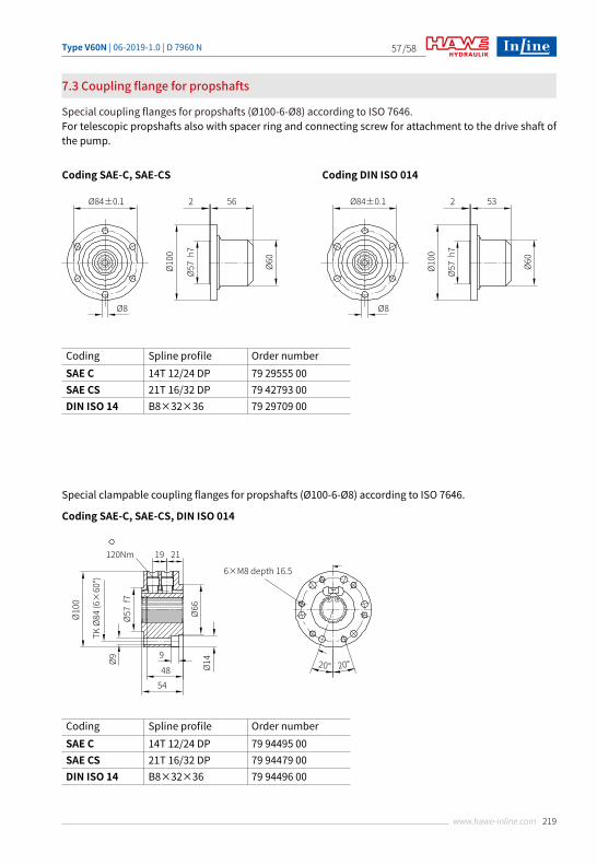
7.3 Coupling flange for propshafts
Special coupling flanges for propshafts (Ø100-6-Ø8) according to ISO 7646.For telescopic propshafts also with spacer ring and connecting screw for attachment to the drive shaft of the pump.
Coding Spline profile Order numberSAE C 14T 12/24 DP 79 29555 00SAE CS 21T 16/32 DP 79 42793 00DIN ISO 14 B8×32×36 79 29709 00
Coding Spline profile Order numberSAE C 14T 12/24 DP 79 94495 00SAE CS 21T 16/32 DP 79 94479 00DIN ISO 14 B8×32×36 79 94496 00
Special clampable coupling flanges for propshafts (Ø100-6-Ø8) according to ISO 7646.
Type V60N | 06-2019-1.0 | D 7960 N/58
220 www.hawe-inline.com
58
• General operating manual for the assembly, initial operation and maintenance of hydraulic components and systems: B 5488• Variable displacement axial piston pump type V40M: D 7961• Variable displacement axial piston pump type V30D: D 7960• Variable displacement axial piston pump type V30E: D 7960 E• Fixed displacement axial piston pump type K60N: D 7960 K• Axial piston motors type M60N: D 7960 M• Proportional directional spool valve, type PSL and PSV size 2: D 7700-2• Proportional directional spool valve, type PSL, PSM and PSV size 3: D 7700-3• Proportional directional spool valve, type PSL, PSM and PSV size 5: D 7700-5• Proportional directional spool valve type PSLF, PSVF and SLF size 3: D 7700-3F• Proportional directional spool valve type PSLF, PSVF and SLF size 5: D 7700-5F• Proportional directional spool valve banks, type PSLF, PSVF and SLF size 7: D 7700-7F• Load-holding valve type LHT: D 7918• Load-holding valve type LHDV: D 7770• Proportional amplifier type EV1M3: D 7831/2• Proportional amplifier type EV1D: D 7831 D
Additional versions
© by HAWE InLine Hydraulik GmbH.The forwarding and reproduction of this document, as well as the use and communication of its contents, are forbidden unless expressely permitted. Any breach or infringement will result in liability for damages. All rights reserved concerning patent or utility model registrations.