Embed Size (px)
Citation preview
Indoor Air Qual i ty
VELOCICALC® Plus Air Velocity Meter
Models 8384/8384A/8385/ 8385A/8386/8386A
Operation and Service Manual
1980321, Revision J July 2010
ENERGY AND COMFORT

Copyright TSI Incorporated / August 2000–2010 / All rights reserved.
Address TSI Incorporated / 500 Cardigan Road / Shoreview, MN 55126 / USA
Fax No. (651) 490-3824
LIMITATION OF WARRANTY AND LIABILITY (effective July 2000) Seller warrants the goods sold hereunder, under normal use and service as described in the operator's manual, shall be free from defects in workmanship and material for twenty-four (24) months, or the length of time specified in the operator's manual, from the date of shipment to the customer. This warranty period is inclusive of any statutory warranty. This limited warranty is subject to the following exclusions: a. Hot-wire or hot-film sensors used with research anemometers, and certain other
components when indicated in specifications, are warranted for 90 days from the date of shipment.
b. Parts repaired or replaced as a result of repair services are warranted to be free from defects in workmanship and material, under normal use, for 90 days from the date of shipment.
c. Seller does not provide any warranty on finished goods manufactured by others or on any fuses, batteries or other consumable materials. Only the original manufacturer's warranty applies.
d. Unless specifically authorized in a separate writing by Seller, Seller makes no warranty with respect to, and shall have no liability in connection with, goods which are incorporated into other products or equipment, or which are modified by any person other than Seller.
The foregoing is IN LIEU OF all other warranties and is subject to the LIMITATIONS stated herein. NO OTHER EXPRESS OR IMPLIED WARRANTY OF FITNESS FOR PARTICULAR PURPOSE OR MERCHANTABILITY IS MADE. TO THE EXTENT PERMITTED BY LAW, THE EXCLUSIVE REMEDY OF THE USER OR BUYER, AND THE LIMIT OF SELLER'S LIABILITY FOR ANY AND ALL LOSSES, INJURIES, OR DAMAGES CONCERNING THE GOODS (INCLUDING CLAIMS BASED ON CONTRACT, NEGLIGENCE, TORT, STRICT LIABILITY OR OTHERWISE) SHALL BE THE RETURN OF GOODS TO SELLER AND THE REFUND OF THE PURCHASE PRICE, OR, AT THE OPTION OF SELLER, THE REPAIR OR REPLACEMENT OF THE GOODS. IN NO EVENT SHALL SELLER BE LIABLE FOR ANY SPECIAL, CONSEQUENTIAL OR INCIDENTAL DAMAGES. SELLER SHALL NOT BE RESPONSIBLE FOR INSTALLATION, DISMANTLING OR REINSTALLATION COSTS OR CHARGES. No Action, regardless of form, may be brought against Seller more than 12 months after a cause of action has accrued. The goods returned under warranty to Seller's factory shall be at Buyer's risk of loss, and will be returned, if at all, at Seller's risk of loss. Buyer and all users are deemed to have accepted this LIMITATION OF WARRANTY AND LIABILITY, which contains the complete and exclusive limited warranty of Seller. This LIMITATION OF WARRANTY AND LIABILITY may not be amended, modified or its terms waived, except by writing signed by an Officer of Seller.
Service Policy Knowing that inoperative or defective instruments are as detrimental to TSI as they are to our customers, our service policy is designed to give prompt attention to any problems. If any malfunction is discovered, please contact your nearest sales office or representative, or call TSI's Customer Service department at (800) 874-2811 (USA) and 1 (651) 490-2811 (International).

CONTENTS Chapters
1. UNPACKING AND PARTS IDENTIFICATION ............................... 1
Parts Identification .......................................................................... 2 2. SETTING-UP ................................................................................... 3
Supplying Power to the VELOCICALC Plus ...................................... 3 Installing the Batteries ............................................................... 3 Using the Optional AC Adapter ................................................. 3
Selecting the Display Units ............................................................. 3 Using The Telescoping Probe ........................................................ 3
Extending The Probe ................................................................. 4 Retracting The Probe ................................................................ 4 Articulating Probe (Models 8384A/8385A/8386A Only) ............ 4
Changing the Real-Time Clock ....................................................... 4 Changing the Baud Rate ................................................................ 4 Connecting the Optional Portable Printer ....................................... 5 Connecting to a Computer .............................................................. 5
3. OPERATION .................................................................................... 7 Keypad Functions ........................................................................... 7 Common Terms .............................................................................. 7 ON/OFF Key...................................................................................... 7 Arrow () Keys ........................................................................... 8 ENTER Key ....................................................................................... 8 Backlight Switch .............................................................................. 8 VELOCITY/FLOWRATE Key ................................................................. 8 PRESSURE (zero) Key (Models 8385/8385A/8386/8386A Only) ..... 9 TEMPERATURE Key .......................................................................... 9 HUMIDITY Key (Model 8386/8386A Only) ...................................... 10 THERMAL/PITOT Key (Models 8385/8385A/8386/8386A Only) ...... 10 ACTUAL/STANDARD Key .................................................................. 10 SAMPLE INTERVAL Key ................................................................... 10 SAMPLE (options) Key .................................................................... 11
Discrete Data Logging (Single Point Measurements) ............. 11 Continuous Data Logging (Multiple Readings Over Time) ...... 11 Setting Data Storage Options .................................................. 11
NEXT TEST (clear) Key ................................................................... 13 STATISTICS (review data) Key ........................................................ 13
To View Statistics .................................................................... 13 To Review Data ....................................................................... 13
HEAT FLOW Key (Model 8386/8386A Only) ................................... 14 Printing Data Using the Portable Printer ...................................... 15
Downloading Data to A Computer ................................................ 15 Data Acquisition (Polling) .............................................................. 16
4. MAINTENANCE ............................................................................. 17 Recalibration ................................................................................. 17 Cases ............................................................................................ 17 Storage .......................................................................................... 17
5. TROUBLESHOOTING................................................................... 19 Appendixes
A. SPECIFICATIONS ........................................................................ 21
B. DIP SWITCH SETTINGS .............................................................. 25
1
Chapter 1
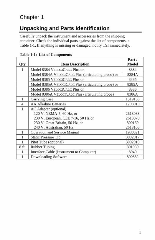
Unpacking and Parts Identification Carefully unpack the instrument and accessories from the shipping container. Check the individual parts against the list of components in Table 1-1. If anything is missing or damaged, notify TSI immediately. Table 1-1: List of Components
Qty Item Description Part / Model
1 Model 8384 VELOCICALC Plus or 8384 Model 8384A VELOCICALC Plus (articulating probe) or 8384A Model 8385 VELOCICALC Plus or 8385 Model 8385A VELOCICALC Plus (articulating probe) or 8385A Model 8386 VELOCICALC Plus or 8386 Model 8386A VELOCICALC Plus (articulating probe) 8386A
1 Carrying Case 1319156 4 AA Alkaline Batteries 1208013 1 AC Adapter (optional)
120 V, NEMA-5, 60 Hz, or 230 V, European, CEE 7/16, 50 Hz or 230 V, Great Britain, 50 Hz, or 240 V, Australian, 50 Hz
2613033 2613078 800169
2613106 1 Operation and Service Manual 1980321 1 Static Pressure Tip 3002017 1 Pitot Tube (optional) 3002018
8 ft. Rubber Tubing 801039 1 Interface Cable (Instrument to Computer) 8940 1 Downloading Software 800832
Chapter 1 2
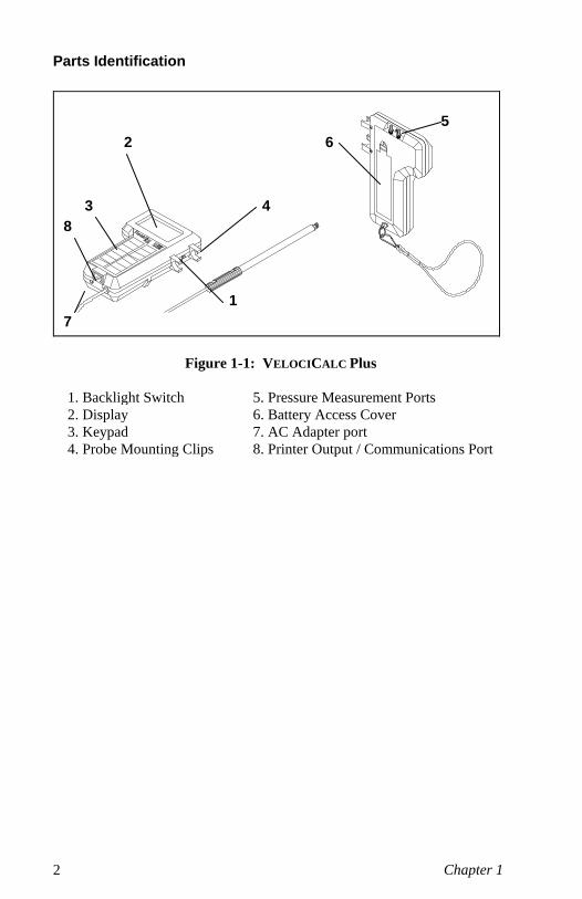
Parts Identification
Figure 1-1: VELOCICALC Plus
1. Backlight Switch 5. Pressure Measurement Ports 2. Display 6. Battery Access Cover 3. Keypad 7. AC Adapter port 4. Probe Mounting Clips 8. Printer Output / Communications Port
4
2 6 5
1
3 8
7

3
Chapter 2
Setting-up
Supplying Power to the VELOCICALC Plus The VELOCICALC Plus can be powered in one of two ways: four size AA batteries or the optional AC adapter.
Installing the Batteries Insert four AA batteries as indicated by the diagram located on the inside of the battery compartment. The VELOCICALC Plus is designed to operate with either alkaline or NiCd rechargeable batteries. Battery life will be shorter if NiCd batteries are used. Carbon-zinc batteries are not recommended because of the danger of battery acid leakage.
Table 2-1 Typical Battery Life at 20°C Air Velocity Alkaline
(ft/min) (m/s) (hrs) 100 0.5 >8.0
5000 25.0 5.0
Using the Optional AC Adapter When using the AC adapter, the batteries (if installed) will be bypassed. The AC adapter is not a battery charger. Be sure to provide the correct voltage and frequency which is marked on the back of the AC adapter.
Selecting the Display Units The VELOCICALC Plus is capable of displaying the measured values in several different measurement units. To change the display units on your VELOCICALC Plus, refer to Appendix B, DIP Switch Settings.
Using the Telescoping Probe The telescoping probe contains the velocity, temperature, and humidity sensors (humidity sensor, Models 8386 and 8386A only). When using the probe, make sure the sensor window is fully exposed and the orientation dimple is facing upstream. NOTE: For temperature and humidity measurements, make sure that at least 3 inches (7.5 cm) of the probe is in the flow to allow the temperature and humidity sensors to be in the air stream.
4 Chapter 2
Extending the Probe To extend the probe, hold the handle in one hand while pulling on the probe tip with the other hand. Do not hold the cable while extending the probe as this prevents the probe from moving.
Retracting the Probe To retract the probe, hold the handle in one hand while pushing on the probe tip with the other hand. If you feel the probe antenna binding, pull gently on the probe cable until the smallest antenna section is retracted. Collapse the rest of the antenna by pressing the probe tip.
Articulating Probe (Models 8384A/8385A/8386A Only) The articulating probe has the ability to bend at a 90° angle for those hard to reach places. To bend the probe, loosen the knurled nut on the joint, bend the probe, and tighten the nut. To straighten the probe, loosen the nut, straighten the probe, and tighten the nut.
Changing the Real-Time Clock The VELOCICALC Plus has an internal real-time clock that keeps track of the time of day (the format is HH.MM where HH is the hour in 24-hour format and MM is minutes) and the date. It is very important to set the time and date correctly, otherwise date and time stamping of recorded data will not be correct. This information has been set to Central Time at the factory before shipping. To change the time and date, press and hold both and keys during the power-up sequence when the time is displayed. Release the keys when the VELOCICALC Plus beeps twice. You will have an opportunity to view and/or change the hours, minutes, year, month, and day of month in sequence. Use the up and down arrow keys () to change any settings. Use the ENTER key to store each setting and advance to the next one.
Changing the Baud Rate The VELOCICALC Plus has a variable baud rate that is used when downloading or printing data from the instrument. By changing the baud rate to a higher rate, the data will be downloaded faster. NOTE: The baud rate must be equal to that of your computer or printer. The instrument baud rate is displayed during the initial power up sequence. To change the baud rate, press and hold both and keys during the power-up sequence while the baud rate is displayed. Release the keys when the VELOCICALC Plus beeps twice. Use the and keys to scroll through the available values of 1200, 2400, 4800, 9600, and 19200. Press ENTER to set the value that is displayed.
Setting-up 5
Connecting the Optional Portable Printer To connect the printer to the VELOCICALC Plus, locate the Printer Interface Cable (supplied with the optional printer) and connect the 9-pin end labeled “PRINTER” to the printer and the other end to the data port of the VELOCICALC Plus. The printer must be set to the same baud rate as the VELOCICALC Plus. See Changing the Baud Rate section for details on how to change the baud rate for the VELOCICALC Plus. To change the baud rate of the printer, please refer to that operation and service manual. Always turn the VELOCICALC Plus on before the printer. If the printer prints question marks (??????), asterisks (******), or random characters, reset it by turning it off and then on again. If necessary, refer to the Portable Printer Manual.
Connecting to a Computer Use the Computer Interface Cable provided with the VELOCICALC Plus to connect the instrument to a computer for downloading stored data or for remote polling. Connect the 9-pin end labeled “COMPUTER” to the computer COM port and the other end to the data port of the VELOCICALC Plus. A 9-pin to 25-pin adapter will be required if your computer has a 25-pin serial port connector. For more information on how to download stored data see Chapter 3 section titled Downloading Data to a Computer. For polling instructions, see Chapter 3 section titled Data Acquisition (Polling).
Caution: This symbol is used to indicate that the data port of the VELOCICALC Plus is not intended for connection to a public telecommunications network. Connect the data port only to another RS232 port.

7
Chapter 3
Operation
Keypad Functions When pressing the keys on the front panel, the VELOCICALC Plus will beep to confirm the function. If you press a key and the VELOCICALC Plus does not beep, then the VELOCICALC Plus does not allow that function during the selected mode.
Common Terms In this manual there are several terms that are used in different places. The following is a brief explanation of the meanings of those terms. Sample: Consists of all of the measurement parameters stored at the same time (a more detailed explanation is found in the Setting Data Storage Options section of this chapter). The maximum number of samples is 1394. Test ID: A group of samples. A test ID can contain one sample or up to 1394 samples. The statistics (average, minimum, maximum, and count) are calculated for each test ID. The maximum number of test IDs is 275. Time Constant: The time constant is an averaging period. It is used to dampen the display. If you are experiencing fluctuating flows, a longer time constant will slow down those fluctuations. The display will update every second, but the displayed reading will be the average over the last time constant period. For example, if the time constant is 10 seconds, the display will update every second, but the displayed reading will be the average from the last 10 seconds. This is also referred to as a “moving average”. Logging Interval: The logging interval is a frequency period that the instrument will log readings. For example, if the logging interval is set to 30 minutes, readings will be taken and recorded every 30 minutes.
ON/OFF Key Press to turn the VELOCICALC Plus on and off. During the power up sequence the display will show the following: all characters, % battery life, % log (memory available), baud rate, time (HH:MM), entered barometric pressure, entered temperature, and then velocity readings.
8 Chapter 3
Arrow () Keys Press to scroll through choices while setting a parameter.
ENTER Key Press to accept a value or condition.
Backlight Switch Slide the switch in the upward position to turn on the backlight. The backlight switch is marked in the international symbols ‘|’ for on and ‘O’ for off. The backlight will remain on until switched off.
VELOCITY/FLOWRATE Key Press to toggle back and forth between displaying velocity and flow rate. In flow rate mode, there are 3 options: flow rate from velocity and area, flow rate from velocity and a horn, and flow rate from pressure and a K factor. These are indicated by circle, rectangle, horn symbol and pressure units. Use keys to scroll through and select the desired symbol, then press ENTER to accept the choice. To change the flow rate mode, press either the or key while displaying flow rate, use the keys to make your selection, then press ENTER to accept the choice. The test ID will automatically increment to the next test ID if flow data has previously been stored in the current test ID. • If circle is chosen:
SIZE will flash on display. Use keys to select size (diameter), then press ENTER to accept the choice and return to measuring.
• If rectangle is chosen:
X SIZE will flash on display. Use keys to select the x-size of the duct, then press ENTER to accept the choice and advance to the next dimension. Y SIZE will flash on display. Use keys to select the y-size of the duct, then press ENTER to accept the choice and return to measuring.
• If horn symbol is chosen:
Use to scroll through horn numbers shown on the display (100, 300, 600, 1200) and Kf symbol, then press ENTER to accept the choice. NOTE: The horn numbers are the models of the horns. For example, 100 refers to a horn model number AM 100. Only horns with Model numbers as follows can be used with this function: AM 100, AM 300, AM 600 and AM 1200. If a horn model number is chosen, the instrument will return to measuring mode and use a preprogrammed curve to calculate flow rate from velocity. If Kf is chosen, the K factor choices will be shown in the following order: last 5 values used, then a
Operation 9
new value which can be adjusted from 0.01 to 999.9. Use the to scroll through the Kf choices, then press ENTER to accept the choice. NOTE: This measurement can only be made with the thermal anemometer sensor, not the Pitot tube.
• If pressure units (in H2O, mm Hg, Pa, hPa, or mm H2O) are chosen: Use keys to select the K factor, then press ENTER to accept the choice. The K factor choices will be shown in the following order: last 5 values used, then a new value which can be adjusted from 0.01 to 999.9. You can zero the pressure while in flow rate from pressure mode by pressing and holding the pressure key for three seconds. The unit will double beep to confirm that the pressure has been zeroed. NOTE: This measurement method is intended for use with diffusers with pressure taps and a manufacturer-supplied K factor.
When measuring velocity or flow rate, and the measurement type is changed, the next time the VELOCITY/FLOWRATE key is pressed, the last measurement used will be displayed. For example, if you were measuring flow rate, switched to measuring humidity, and then back to VELOCITY/ FLOWRATE, the VELOCICALC Plus will go back to displaying flow rate. If you were measuring velocity, then humidity, and returned to VELOCITY/ FLOWRATE, the instrument will return to velocity.
PRESSURE (zero) Key (Models 8385/8385A/8386/8386A Only) Press and release to display pressure. Press and hold for three seconds to zero the pressure reading. The unit will double beep to confirm that the pressure has been zeroed. NOTE: Make sure that all tubing is disconnected or open to ambient conditions before zeroing.
TEMPERATURE Key Press and release to display temperature on the large digits instead of showing it on the small digits. Temperature is usually displayed on the small digits when other measurement types are on the large digits. NOTE: For temperature and humidity measurements, make sure that at least 3 inches (7.5 cm) of the probe is in the flow to allow the temperature and humidity sensors to be in the air stream.
10 Chapter 3
HUMIDITY Key (Model 8386/8386A Only) Press to toggle between displaying % relative humidity, dew point temperature, and wet bulb temperature on the large digits. (The first time that the button is pushed it will display the last measurement type that was displayed.) NOTE: To display accurate wet bulb temperature, the correct barometric pressure must be entered. See Actual/Standard Key section for details on setting the barometric pressure. NOTE: For temperature and humidity measurements, make sure that at least 3 inches (7.5 cm) of the probe is in the flow to allow the temperature and humidity sensors to be in the air stream.
THERMAL/PITOT Key (Models 8385/8385A/8386/8386A Only) Press to toggle back and forth between measuring velocity or flow rate with the thermal anemometer sensor or with a Pitot tube attached to the pressure ports. NOTE: If this key is pressed while displaying anything other than velocity or flowrate, it will have no effect on the readings.
ACTUAL/STANDARD Key Press to toggle between displaying actual and standard velocity or flow rate. Press and hold to view, enter, or change ambient conditions. When the key is pressed and held, the pressure units will flash and the last barometric pressure entered will be displayed. Use the keys to change the barometric pressure and press ENTER to accept it. Then the temperature units will flash and the last temperature entered will be displayed. Use the keys to change the temperature and press ENTER to accept it and return to measuring mode. The ranges that can be entered are as follows: Pressure: 15 to 40 in. Hg (381 to 1016 mm Hg), 29.92 in. Hg (760 mm Hg) is default; Temperature: -80 to 400°F (-62 to 204°C), 70°F (21.1°C) is default. NOTE: When obtaining wet bulb temperature or heat flow readings, the correct barometric pressure must be entered. Both the barometric pressure and temperature need to be entered when measuring the following: 1) actual velocity (or flow rate) with either the thermal anemometer or the Pitot tube, or 2) standard velocity (or flow rate) with a Pitot tube.
SAMPLE INTERVAL Key The SAMPLE INTERVAL key is used to set the time constant and logging intervals. Press to display current time constant. Use to scroll through the time constant choices, which are 1 s, 2 s, 5 s, 10 s, 15 s, 20 s, and LOG symbol, then press ENTER to accept the choice. If LOG was chosen, the first logging interval choice will be displayed. Use to scroll through the logging interval choices, which are 2 s, 5 s, 10 s, 15 s, 20 s, 30 s, 1 min, 2 min, 5 min, 10 min, 15 min, 20 min, 30 min, 60 min, and OFF. Press ENTER to accept choice and return to measuring mode. If a logging interval is chosen that is shorter than the time constant, the time constant will be shortened to be equal to the logging interval.
Operation 11
NOTE: To operate the instrument in discrete data logging (or single point) mode, the logging interval must be set to OFF. To operate the instrument in continuous data logging mode, the logging interval must be set to something other than OFF.
SAMPLE (options) Key
Discrete Data Logging (Single Point Measurements) The instrument must first be in discrete data logging mode. See SAMPLE INTERVAL Key section for more details. Press the SAMPLE key to take a sample. The sample that gets stored is the measurement types that were chosen in sample options (see Setting Data Storage Options for more details) and the measurement type that is on the large digits. While the sample is being taken, the small digits will read the sample number, the COUNT indicator will be lit, and the SAMPLE indicator will flash during the length of the sample. The sample will last until the length of a time constant has passed. Then the VELOCICALC Plus will display the sample number and the value that was recorded.
Continuous Data Logging (Multiple Readings Over Time) The instrument must first be in continuous data logging mode. See SAMPLE INTERVAL Key section for more details. Press the SAMPLE key to start a sample. The parameters that are stored are those that were turned on in the options menu as well as that on the large digits. Samples will be taken at intervals that were set in the SAMPLE INTERVAL menu (see the SAMPLE INTERVAL Key section for more details). The display will light LOG while samples are being taken and SAMPLE will light as the data is stored. Press the SAMPLE key again to stop the sample. The display will then scroll through the following: number of samples stored, test ID number and average of the measurements that were stored. To review this data and/or individual data points, please see STATISTICS (review data) Key section.
Setting Data Storage Options In this section the terms “On” and “AUtO” are referred to. The following brief explanations may help to understand what function is being performed. “On” means that measurement type will log whenever the SAMPLE key is pressed. “AUtO” means that measurement type will automatically log if it is needed to calculate the measurement type on the large digits when the SAMPLE key is pressed. For example, if dew point is being displayed on the large display digits and SAMPLE is pressed, then dew point, humidity, and temperature will all be stored automatically because dew point is calculated using
12 Chapter 3
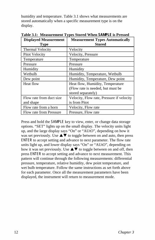
humidity and temperature. Table 3.1 shows what measurements are stored automatically when a specific measurement type is on the display. Table 3.1: Measurement Types Stored When SAMPLE is Pressed
Displayed Measurement Type
Measurement Types Automatically Stored
Thermal Velocity Velocity Pitot Velocity Velocity, Pressure Temperature Temperature Pressure Pressure Humidity Humidity Wetbulb Humidity, Temperature, Wetbulb Dew point Humidity, Temperature, Dew point Heat flow Heat flow, Humidity, Temperature
(Flow rate is needed, but must be stored separately)
Flow rate from duct size and shape
Velocity, Flow rate, Pressure if velocity is from Pitot
Flow rate from a horn Velocity, Flow rate Flow rate from Pressure Pressure, Flow rate
Press and hold the SAMPLE key to view, enter, or change data storage options. “SET” lights up on the small display. The velocity units light up, and the large display says “On” or “AUtO”, depending on how it was set previously. Use to toggle between on and auto, then press ENTER to accept setting and advance to next parameter. The flow rate units light up, and lower display says “On” or “AUtO”, depending on how it was set previously. Use to toggle between on and off, then press ENTER to accept setting and advance to next measurement. This pattern will continue through the following measurements: differential pressure, temperature, relative humidity, dew point temperature, and wet bulb temperature. Follow the same instructions as set forth above for each parameter. Once all the measurement parameters have been displayed, the instrument will return to measurement mode.
Operation 13
NEXT TEST (clear) Key Press to advance to the next test ID. If the current test ID does not have anything stored, it will not advance to the next test ID. To clear the last sample, press and hold the key and the display will begin a countdown from 5 to 0. Release the key at any time during the countdown before zero is displayed. To clear all memory, keep holding key during the countdown. Release the key when 0 is displayed. The display will flash ‘CLEAR LOG’. NOTE: Only the last sample recorded can be cleared without clearing the entire memory. You cannot go back to a previous test ID and clear a single reading. Also, you cannot add data to a previous test ID. Sample clear does not work in continuous data logging mode.
STATISTICS (review data) Key The STATISTICS key has two purposes. One is to view the statistics for the currently displayed parameter and the other is review data for a particular test ID.
To View Statistics Press STATISTICS to view statistics for the parameter currently shown on the large digits. The count will be shown on the small digits and the test ID on the large digits. Count will stay on the small digits and the large digits will change to displaying average. Press STATISTICS again (before the average disappears from the display) to proceed to maximum and again to display minimum.
To Review Data Press and hold STATISTICS. The VELOCICALC Plus will beep twice, release the key and the test ID number will be displayed on the small digits and the TEST ID symbol will light up. Use to select the desired test ID. Press ENTER to accept the test ID number. Use to select and view average, maximum, minimum, count, and individual sample numbers with values for the selected test ID. The samples will be displayed in the order that they were taken, from the first sample of that test ID to the last. To view a different test ID, press STATISTICS again to return to test ID on small digits and nothing on large digits. Use to choose a new test ID, then press ENTER to accept the choice and continue as above to review the data. To review data of a different measurement type, press the desired measurement type button while AVG, MAX, MIN, COUNT or sample is being displayed. If there is no data for that measurement type, “----” will be displayed. Press another measurement type key to view more data or press ENTER to return to measuring mode.
14 Chapter 3
HEAT FLOW Key (Model 8386/8386A Only) In order for the VELOCICALC Plus to calculate heat flow, the flow rate, temperature, and humidity need to be recorded at one location before the heating (or cooling) source and one location after the source. The data at these locations must be stored in two sequential test IDs. The first test ID is used as reference for calculating heat flow in the second test ID. To store the required data for heat flow calculations, proceed as outlined below. 1. Make sure that the correct barometric pressure is entered in the
instrument or the obtained readings will be incorrect. If flow is being measured from a Pitot tube, make sure the correct flow temperature is also entered. The flow rate displayed must be is STANDARD flow, not ACTUAL flow, or the “nO rEF” message will appear on the display. This message indicates that there is missing or incorrect reference data for calculating heat flow. (See ACTUAL/STANDARD Key section for details on setting these parameters.)
2. Make sure the instrument is in discrete (or single point) sampling mode. (See SAMPLE INTERVAL Key and SAMPLE (options) Key sections for details on how to be in discrete sampling mode.)
3. Press NEXT TEST to start a new test ID. 4. Press VELOCITY/FLOWRATE key to display flowrate. 5. Press SAMPLE key and store multiple readings at the first (reference)
location. Taking several samples in the traverse of the duct provides accurate average readings.
6. Press TEMPERATURE key. 7. Press SAMPLE to record the temperature readings. 8. Press HUMIDITY key to display relative humidity (% RH). 9. Press SAMPLE to record the relative humidity. 10. Press NEXT TEST key to advance to the next test ID. Move probe to the
second location. (Make sure that at least 3 inches (7.5 cm) of the probe are in the flow to allow the temperature and humidity sensors to be in the air stream.)
11. Press HEAT FLOW key to get instantaneous readings of sensible heat flow. Press key three more times to display latent heat flow, total heat flow, and sensible heat factor.
12. Press SAMPLE key to store readings at second location.
Operation 15
To record readings of heat flow over time, proceed as above with steps 1-11 and then follow the steps below. 1. Change from discrete to continuous data logging (See SAMPLE
INTERVAL Key and SAMPLE (options) Key sections for details on how to change to continuous sampling mode).
2. Press SAMPLE to start a sample. This will automatically log data that is required.
3. Press SAMPLE to stop the sample.
This will allow you to record data over time which, when downloaded to a computer, can be graphed.
Printing Data Using the Portable Printer The following will be printed as long as a printer is connected. When viewing statistics, the statistics shown on the display for the current test ID will be printed automatically when the STATISTICS key is pressed. When reviewing data, nothing will print. When taking a sample, the reading will be printed automatically each time the SAMPLE key is pressed. To print everything in memory, press and hold the ENTER key. This will initiate a countdown from 5 to 0. When the display shows zero, release the key and everything in memory will print to the printer. The display will read “Send dAtA” while dumping the memory. If you release the key at any time other than 0 during the countdown, nothing will print. To stop printing at any time, turn the VELOCICALC Plus off. NOTE: In order to print, the baud rate on the VELOCICALC Plus must be set to the same as the printer (default is 1200).
Downloading Data to a Computer “LOGDAT” is a windows-based program from TSI designed to download the data stored in the memory of the VELOCICALC Plus to a computer. This data includes the test ID, measurement, unit of measure, flow area, and sample interval. This data is date and time stamped. In addition, the statistics for each test ID are provided. The file containing the downloaded data is sorted and tab delimited to allow it to be imported into a spreadsheet for further data analysis. To install LogDat software, run the SETUP.EXE file on the LogDat distribution disc. Once you open the program, it is self-directing and provides all the necessary instructions for downloading data.
To download data from the VELOCICALC Plus, connect the supplied computer interface cable to the VELOCICALC Plus and to a computer serial port. Any serial port from COM1 to COM4 can be used.
16 Chapter 3
Data Acquisition (Polling) The VELOCICALC Plus is designed to allow you to perform polling through the use of a computer. To do this your computer must be hooked up and in terminal mode and the baud rate for the computer and the VELOCICALC Plus must be set to the same value. For details on viewing or changing the baud rate see Changing the Baud Rate section in Chapter 2. You must then send an upper case V to the instrument. The values that are sent back to the computer are for those measurement types that are turned “on” in “Sample Options” menu. See Setting Data Storage Options and SAMPLE INTERVAL Key sections earlier in this chapter for more details. You must write their own routine (program) to obtain information at specific intervals from the VELOCICALC Plus. The meter will only print information when the SAMPLE button is pressed.
Caution: This symbol is used to indicate that the data port of the VELOCICALC Plus is not intended for connection to a public telecommunications network. Connect the data port only to another RS232 port.
17
Chapter 4
Maintenance The VELOCICALC Plus requires very little maintenance to keep it performing well.
Recalibration To maintain a high degree of accuracy in your measurements, we recommend that you return your VELOCICALC Plus to TSI for annual recalibration. For a reasonable fee, we will quickly recalibrate the unit and return it to you in “as new” working condition; it is especially important in applications where strict calibration records must be maintained. Please contact one of TSI’s offices or your local distributor to make service arrangements and to receive a Return Material Authorization (RMA) number. To fill out an online RMA form, visit TSI’s website at http://rma.tsi.com. U.S. & International TSI Incorporated 500 Cardigan Road Shoreview MN 55126-3996 Tel: (800) 874-2811 (651) 490-2811 Fax: (651) 490-3824
Cases If the instrument case or storage case needs cleaning, wipe it off with a soft cloth and isopropyl alcohol or a mild detergent. Never immerse the VELOCICALC Plus. If the enclosure of the VELOCICALC Plus or the AC adapter becomes broken, it must be replaced immediately to prevent access to hazardous voltage.
Storage When storing the VELOCICALC Plus for more than one month, removing the batteries is recommended. This prevents damage due to battery leakage.

19
Chapter 5
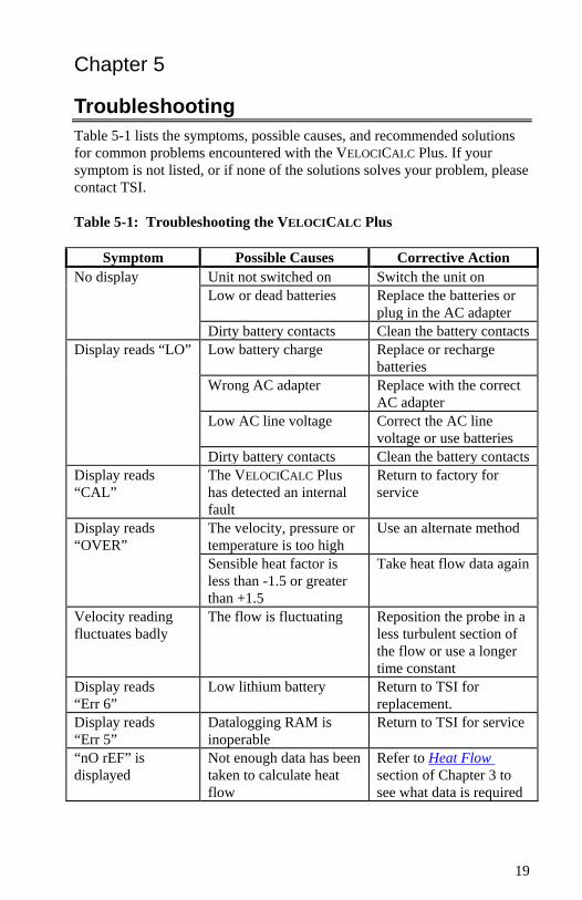
Troubleshooting Table 5-1 lists the symptoms, possible causes, and recommended solutions for common problems encountered with the VELOCICALC Plus. If your symptom is not listed, or if none of the solutions solves your problem, please contact TSI. Table 5-1: Troubleshooting the VELOCICALC Plus
Symptom Possible Causes Corrective Action No display Unit not switched on Switch the unit on Low or dead batteries Replace the batteries or
plug in the AC adapter Dirty battery contacts Clean the battery contacts Display reads “LO” Low battery charge Replace or recharge
batteries Wrong AC adapter Replace with the correct
AC adapter Low AC line voltage Correct the AC line
voltage or use batteries Dirty battery contacts Clean the battery contacts Display reads “CAL”
The VELOCICALC Plus has detected an internal fault
Return to factory for service
Display reads “OVER”
The velocity, pressure or temperature is too high
Use an alternate method
Sensible heat factor is less than -1.5 or greater than +1.5
Take heat flow data again
Velocity reading fluctuates badly
The flow is fluctuating Reposition the probe in a less turbulent section of the flow or use a longer time constant
Display reads “Err 6”
Low lithium battery Return to TSI for replacement.
Display reads “Err 5”
Datalogging RAM is inoperable
Return to TSI for service
“nO rEF” is displayed
Not enough data has been taken to calculate heat flow
Refer to Heat Flow section of Chapter 3 to see what data is required
20 Chapter 5
WARNING! Remove the probe from excessive temperature immediately: excessive heat can damage the sensor. Operating temperature limits can be found in Appendix A (Specifications). The pressure sensor is protected from damage up to 7 psi (48 kPa or 360 mmHg). At higher pressure it can burst!
21
Appendix A
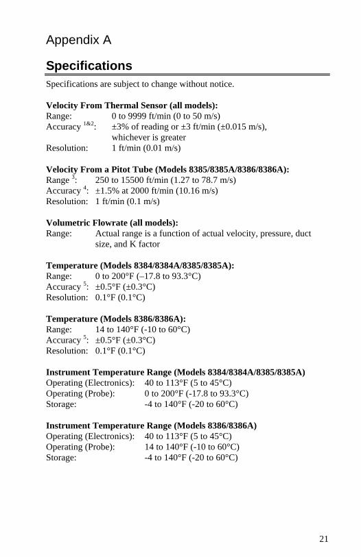
Specifications Specifications are subject to change without notice. Velocity From Thermal Sensor (all models): Range: 0 to 9999 ft/min (0 to 50 m/s) Accuracy 1&2: ±3% of reading or ±3 ft/min (±0.015 m/s),
whichever is greater Resolution: 1 ft/min (0.01 m/s) Velocity From a Pitot Tube (Models 8385/8385A/8386/8386A): Range 3: 250 to 15500 ft/min (1.27 to 78.7 m/s) Accuracy 4: ±1.5% at 2000 ft/min (10.16 m/s) Resolution: 1 ft/min (0.1 m/s) Volumetric Flowrate (all models): Range: Actual range is a function of actual velocity, pressure, duct
size, and K factor Temperature (Models 8384/8384A/8385/8385A): Range: 0 to 200°F (–17.8 to 93.3°C) Accuracy 5: ±0.5°F (±0.3°C) Resolution: 0.1°F (0.1°C) Temperature (Models 8386/8386A): Range: 14 to 140°F (-10 to 60°C) Accuracy 5: ±0.5°F (±0.3°C) Resolution: 0.1°F (0.1°C) Instrument Temperature Range (Models 8384/8384A/8385/8385A) Operating (Electronics): 40 to 113°F (5 to 45°C) Operating (Probe): 0 to 200°F (-17.8 to 93.3°C) Storage: -4 to 140°F (-20 to 60°C) Instrument Temperature Range (Models 8386/8386A) Operating (Electronics): 40 to 113°F (5 to 45°C) Operating (Probe): 14 to 140°F (-10 to 60°C) Storage: -4 to 140°F (-20 to 60°C)
22 Appendix A
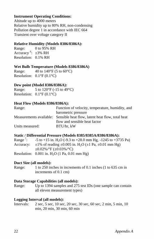
Instrument Operating Conditions: Altitude up to 4000 meters Relative humidity up to 80% RH, non-condensing Pollution degree 1 in accordance with IEC 664 Transient over voltage category II Relative Humidity (Models 8386/8386A): Range: 0 to 95% RH Accuracy 6: ±3% RH Resolution: 0.1% RH Wet Bulb Temperature (Models 8386/8386A) Range: 40 to 140°F (5 to 60°C) Resolution: 0.1°F (0.1°C) Dew point (Model 8386/8386A): Range: 5 to 120°F (-15 to 49°C) Resolution: 0.1°F (0.1°C) Heat Flow (Models 8386/8386A): Range: Function of velocity, temperature, humidity, and
barometric pressure Measurements available: Sensible heat flow, latent heat flow, total heat
flow and sensible heat factor Units measured: BTU/hr, kW Static / Differential Pressure (Models 8385/8385A/8386/8386A): Range 7: -5 to +15 in. H2O (-9.3 to +28.0 mm Hg, -1245 to +3735 Pa) Accuracy: ±1% of reading ±0.005 in. H2O (±1 Pa, ±0.01 mm Hg)
±0.02%/°F (±0.03%/°C) Resolution: 0.001 in. H2O (1 Pa, 0.01 mm Hg) Duct Size (all models): Range: 1 to 250 inches in increments of 0.1 inches (1 to 635 cm in
increments of 0.1 cm) Data Storage Capabilities (all models): Range: Up to 1394 samples and 275 test IDs (one sample can contain
all eleven measurement types) Logging Interval (all models): Intervals: 2 sec, 5 sec, 10 sec, 20 sec, 30 sec, 60 sec, 2 min, 5 min, 10
min, 20 min, 30 min, 60 min
Specifications 23
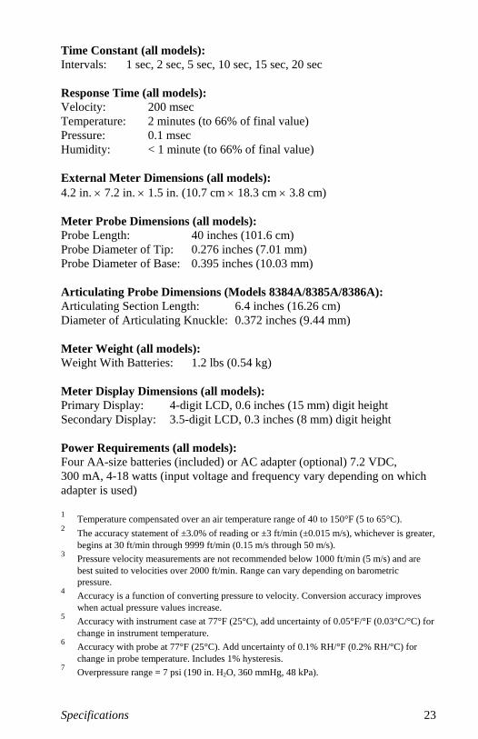
Time Constant (all models): Intervals: 1 sec, 2 sec, 5 sec, 10 sec, 15 sec, 20 sec Response Time (all models): Velocity: 200 msec Temperature: 2 minutes (to 66% of final value) Pressure: 0.1 msec Humidity: < 1 minute (to 66% of final value) External Meter Dimensions (all models): 4.2 in. × 7.2 in. × 1.5 in. (10.7 cm × 18.3 cm × 3.8 cm) Meter Probe Dimensions (all models): Probe Length: 40 inches (101.6 cm) Probe Diameter of Tip: 0.276 inches (7.01 mm) Probe Diameter of Base: 0.395 inches (10.03 mm) Articulating Probe Dimensions (Models 8384A/8385A/8386A): Articulating Section Length: 6.4 inches (16.26 cm) Diameter of Articulating Knuckle: 0.372 inches (9.44 mm) Meter Weight (all models): Weight With Batteries: 1.2 lbs (0.54 kg) Meter Display Dimensions (all models): Primary Display: 4-digit LCD, 0.6 inches (15 mm) digit height Secondary Display: 3.5-digit LCD, 0.3 inches (8 mm) digit height Power Requirements (all models): Four AA-size batteries (included) or AC adapter (optional) 7.2 VDC, 300 mA, 4-18 watts (input voltage and frequency vary depending on which adapter is used) 1 Temperature compensated over an air temperature range of 40 to 150°F (5 to 65°C). 2 The accuracy statement of ±3.0% of reading or ±3 ft/min (±0.015 m/s), whichever is greater,
begins at 30 ft/min through 9999 ft/min (0.15 m/s through 50 m/s). 3 Pressure velocity measurements are not recommended below 1000 ft/min (5 m/s) and are
best suited to velocities over 2000 ft/min. Range can vary depending on barometric pressure.
4 Accuracy is a function of converting pressure to velocity. Conversion accuracy improves when actual pressure values increase.
5 Accuracy with instrument case at 77°F (25°C), add uncertainty of 0.05°F/°F (0.03°C/°C) for change in instrument temperature.
6 Accuracy with probe at 77°F (25°C). Add uncertainty of 0.1% RH/°F (0.2% RH/°C) for change in probe temperature. Includes 1% hysteresis.
7 Overpressure range = 7 psi (190 in. H2O, 360 mmHg, 48 kPa).

25
Appendix B
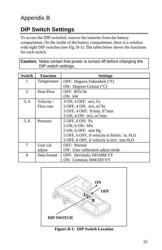
DIP Switch Settings To access the DIP switched, remove the batteries from the battery compartment. On the inside of the battery compartment, there is a window with eight DIP switches (see Fig. B-1). The table below shows the functions for each switch.
Caution: Make certain that power is turned off before changing the DIP switch settings.
Switch Function Settings
1 Temperature OFF: Degrees Fahrenheit (°F) ON: Degrees Celsius (°C)
2 Heat Flow OFF: BTU/hr ON: kW
3, 4 Velocity / Flow rate
3 ON, 4 OFF: m/s, l/s 3 OFF, 4 ON: m/s, m3/hr 3 OFF, 4 OFF: ft/min, ft3/min 3 ON, 4 ON: m/s, m3/min
5, 6 Pressure 5 OFF, 6 ON: Pa 5 ON, 6 ON: hPa 5 ON, 6 OFF: mm Hg 5 OFF, 6 OFF, if velocity is ft/min: in. H2O 5 OFF, 6 OFF, if velocity is m/s: mm H2O
7 User cal. adjust
OFF: Normal ON: User calibration adjust mode
8 Data format OFF: Decimals; DD:MM:YY ON: Commas; MM:DD:YY
DIP SWITCH
ON
OFF1
8
Figure B-1: DIP Switch Location

TSI Incorporated – 500 Cardigan Road, Shoreview, MN 55126 U.S.A USA Tel: +1 800 874 2811 E-mail: [email protected] Website: www.tsi.com UK Tel: +44 149 4 459200 E-mail: [email protected] Website: www.tsiinc.co.uk France Tel: +33 491 11 87 64 E-mail: [email protected] Website: www.tsiinc.fr Germany Tel: +49 241 523030 E-mail: [email protected] Website: www.tsiinc.de India Tel: +91 80 41132470 E-mail: [email protected] China Tel: +86 10 8260 1595 E-mail: [email protected] Singapore Tel: +65 6595 6388 E-mail: [email protected] Contact your local TSI Distributor or visit our website www.tsi.com for more detailed specifications. P/N 1980321 Rev. J Copyright © 2010 by TSI Incorporated Printed in U.S.A