Embed Size (px)
Citation preview
UTTAR PRADESH EXPRESSWAYS INDUSTRIAL DEVELOPMENT AUTHORITY
(UPEIDA)
Government of Uttar Pradesh
Development of Purvanchal Expressway (PackageV)
From Sansarpur (Dist. Sultanpur) to Gobindpur (Dist. Azamgarh) (Km 164+300 to Km 218+300)
in the State of Uttar Pradesh on EPC Basis
MAIN REPORT
C‐13, 2nd Floor, Paryatan Bhawan Vipin Khand, Gomti Nagar
Lucknow – 226010
The Purvanchal Expressway Project Project Report
UPEIDA 1
EXECUTIVE SUMMARY
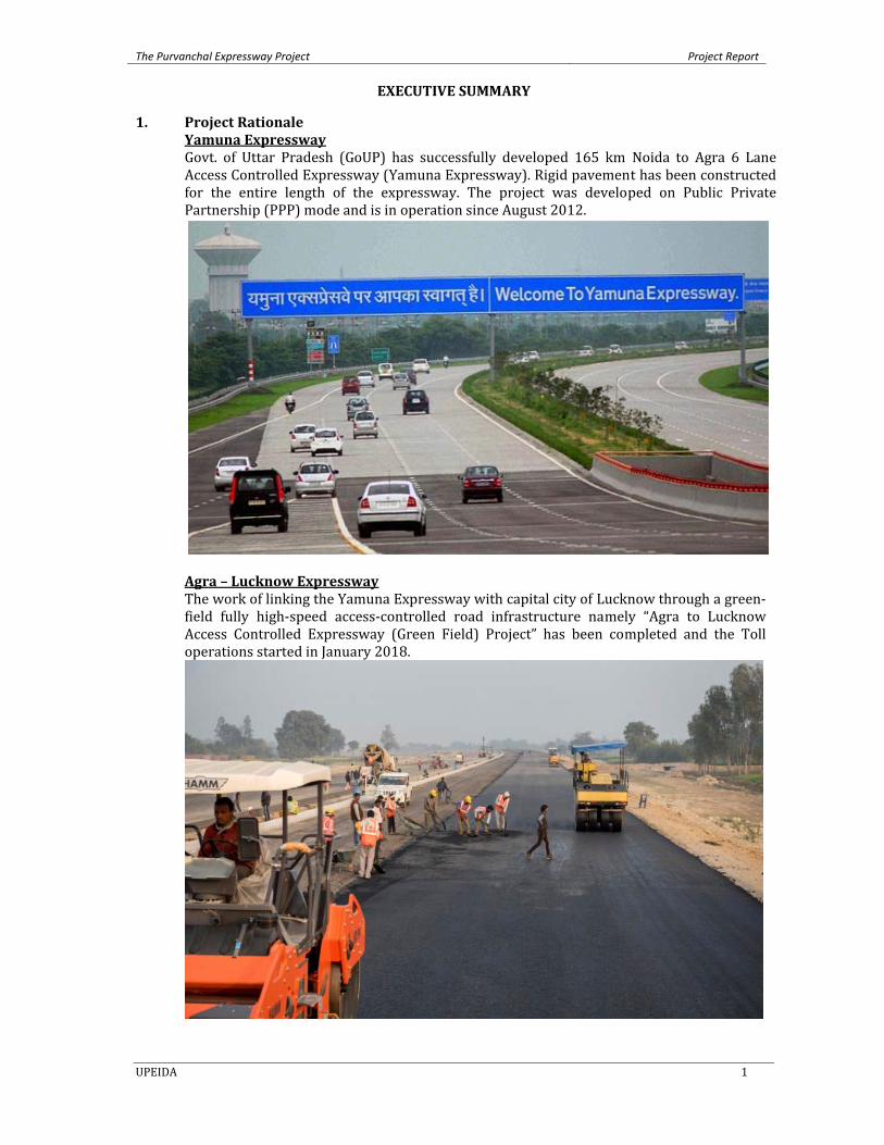
1. Project Rationale Yamuna Expressway Govt. of Uttar Pradesh (GoUP) has successfully developed 165 km Noida to Agra 6 Lane Access Controlled Expressway (Yamuna Expressway). Rigid pavement has been constructed for the entire length of the expressway. The project was developed on Public Private Partnership (PPP) mode and is in operation since August 2012.
Agra – Lucknow Expressway The work of linking the Yamuna Expressway with capital city of Lucknow through a green‐field fully high‐speed access‐controlled road infrastructure namely “Agra to Lucknow Access Controlled Expressway (Green Field) Project” has been completed and the Toll operations started in January 2018.
The Purvanchal Expressway Project Project Report
UPEIDA 2
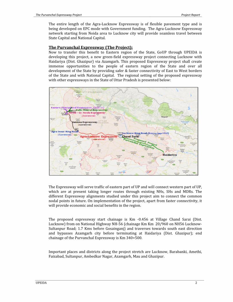
The entire length of the Agra‐Lucknow Expressway is of flexible pavement type and is being developed on EPC mode with Government funding. The Agra‐Lucknow Expressway network starting from Noida area to Lucknow city will provide seamless travel between State Capital and National Capital. The Purvanchal Expressway (The Project): Now to transfer this benefit to Eastern region of the State, GoUP through UPEIDA is developing this project, a new green‐field expressway project connecting Lucknow with Haidariya (Dist. Ghazipur) via Azamgarh. This proposed Expressway project shall create immense opportunities to the people of eastern region of the State and over all development of the State by providing safer & faster connectivity of East to West borders of the State and with National Capital. The regional setting of the proposed expressway with other expressways in the State of Uttar Pradesh is presented below:
The Expressway will serve traffic of eastern part of UP and will connect western part of UP, which are at present taking longer routes through existing NHs, SHs and MDRs. The different Expressway alignments studied under this project aim to connect the common nodal points in future. On implementation of the project, apart from faster connectivity, it will provide economic and social benefits in the region. The proposed expressway start chainage is Km ‐0.456 at Village Chand Sarai (Dist. Lucknow) from on National Highway NH‐56 (chainage Km Km 20/960 on NH56 Lucknow‐Sultanpur Road; 1.7 Kms before Gosainganj) and traverses towards south east direction and bypasses Azamgarh city before terminating at Haidariya (Dist. Ghazipur); end chainage of the Purvanchal Expressway is Km 340+500. Important places and districts along the project stretch are Lucknow, Barabanki, Amethi, Faizabad, Sultanpur, Ambedkar Nagar, Azamgarh, Mau and Ghazipur.
The Purvanchal Expressway Project Project Report
UPEIDA 3
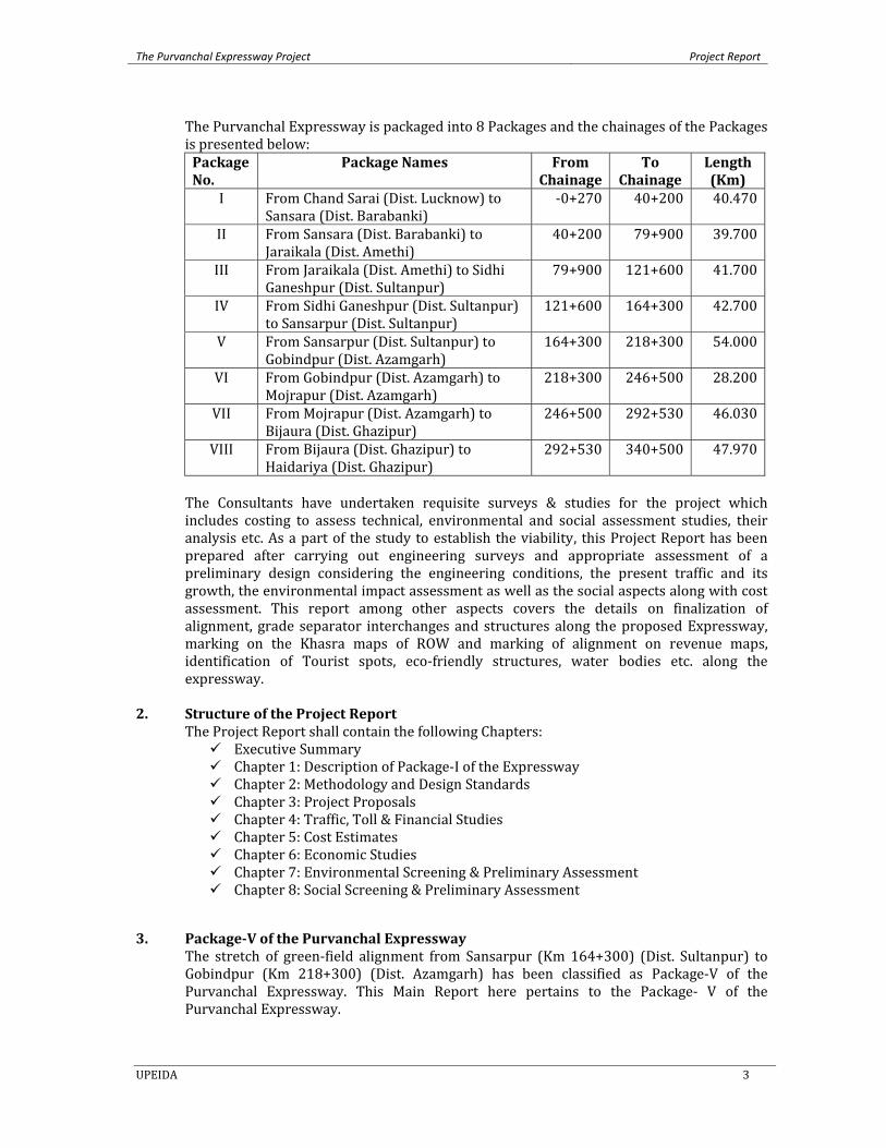
The Purvanchal Expressway is packaged into 8 Packages and the chainages of the Packages is presented below: Package No.
Package Names From Chainage
To Chainage
Length (Km)
I From Chand Sarai (Dist. Lucknow) to Sansara (Dist. Barabanki)
‐0+270 40+200 40.470
II From Sansara (Dist. Barabanki) to Jaraikala (Dist. Amethi)
40+200 79+900 39.700
III From Jaraikala (Dist. Amethi) to Sidhi Ganeshpur (Dist. Sultanpur)
79+900 121+600 41.700
IV From Sidhi Ganeshpur (Dist. Sultanpur) to Sansarpur (Dist. Sultanpur)
121+600 164+300 42.700
V From Sansarpur (Dist. Sultanpur) to Gobindpur (Dist. Azamgarh)
164+300 218+300 54.000
VI From Gobindpur (Dist. Azamgarh) to Mojrapur (Dist. Azamgarh)
218+300 246+500 28.200
VII From Mojrapur (Dist. Azamgarh) to Bijaura (Dist. Ghazipur)
246+500 292+530 46.030
VIII From Bijaura (Dist. Ghazipur) to Haidariya (Dist. Ghazipur)
292+530 340+500 47.970
The Consultants have undertaken requisite surveys & studies for the project which includes costing to assess technical, environmental and social assessment studies, their analysis etc. As a part of the study to establish the viability, this Project Report has been prepared after carrying out engineering surveys and appropriate assessment of a preliminary design considering the engineering conditions, the present traffic and its growth, the environmental impact assessment as well as the social aspects along with cost assessment. This report among other aspects covers the details on finalization of alignment, grade separator interchanges and structures along the proposed Expressway, marking on the Khasra maps of ROW and marking of alignment on revenue maps, identification of Tourist spots, eco‐friendly structures, water bodies etc. along the expressway.
2. Structure of the Project Report The Project Report shall contain the following Chapters:
Executive Summary Chapter 1: Description of Package‐I of the Expressway Chapter 2: Methodology and Design Standards Chapter 3: Project Proposals Chapter 4: Traffic, Toll & Financial Studies Chapter 5: Cost Estimates Chapter 6: Economic Studies Chapter 7: Environmental Screening & Preliminary Assessment Chapter 8: Social Screening & Preliminary Assessment
3. PackageV of the Purvanchal Expressway The stretch of green‐field alignment from Sansarpur (Km 164+300) (Dist. Sultanpur) to Gobindpur (Km 218+300) (Dist. Azamgarh) has been classified as Package‐V of the Purvanchal Expressway. This Main Report here pertains to the Package‐ V of the Purvanchal Expressway.
The Purvanchal Expressway Project Project Report
UPEIDA 4
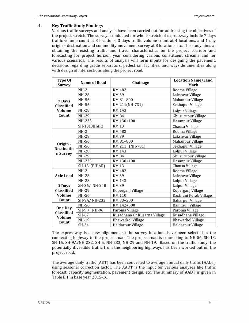
4. Key Traffic Study Findings Various traffic surveys and analysis have been carried out for addressing the objectives of the project stretch. The surveys conducted for whole stretch of expressway include 7 days traffic volume count at 8 locations, 3 days traffic volume count at 4 locations, and 1 day origin – destination and commodity movement survey at 8 locations etc. The study aims at obtaining the existing traffic and travel characteristics on the project corridor and forecasting for project horizon year considering various constituent streams and for various scenarios. The results of analysis will form inputs for designing the pavement, decisions regarding grade separators, pedestrian facilities, and wayside amenities along with design of intersections along the project road. Type Of Survey Name of Road Chainage
Location Name/Land Mark
7 Days Classified Volume Count
NH‐2 KM 482 Rooma Village NH‐28 KM 39 Lakshvar Village NH‐56 KM 81+800 Mahanpur Village NH‐56 KM 211(NH‐731) Sekhapur VillageNH‐28 KM 143 Lolpur Village NH‐29 KM 84 Ghusurupur VillageNH‐233 KM 130+100 Hasanpur Village SH‐13(BIHAR) KM 13 Chausa Village
Origin Destination Survey
NH‐2 KM 482 Rooma Village NH‐28 KM 39 Lakshvar Village NH‐56 KM 81+800 Mahanpur Village NH‐56 KM 211 (NH‐731) Sekhapur VillageNH‐28 KM 143 Lolpur Village NH‐29 KM 84 Ghusurupur VillageNH‐233 KM 130+100 Hasanpur Village SH‐13 (BIHAR) KM 13 Chausa Village
Axle Load NH‐2 KM 482 Rooma Village NH‐28 KM 39 Lakshvar Village NH‐28 KM 143 Lolpur Village
3 Days Classified Volume Count
SH‐36/ NH‐24B KM 39 Lalpur Village NH‐29 Koperganj Village Koperganj Village NH‐56 KM 110 Kasthuni Purab Village SH‐9A/ NH‐232 KM 33+200 Baharpur Village
One Day Classified Volume Count
NH‐56 KM 142+500 Kamrauli Village SH‐9 / NH‐96 Paroma Village Paroma Village SH‐67 Kusadhana Or Kusarna Village Kusadhana Village NH‐19 Bhawarkol Village Bhawarkol Village SH‐34 Haldarpur Village Haldarpur Village
The expressway is a new alignment so the survey locations have been selected at the connecting highway to the project road. The project road is connecting to NH‐56, SH‐13, SH‐15, SH‐9A/NH‐232, SH‐5, NH‐233, NH‐29 and NH‐19. Based on the traffic study, the potentially divertible traffic from the neighboring highways has been worked out on the project road. The average daily traffic (ADT) has been converted to average annual daily traffic (AADT) using seasonal correction factor. The AADT is the input for various analyses like traffic forecast, capacity augmentation, pavement design, etc. The summary of AADT is given in Table E.1 in base year 2015‐16.
The Purvanchal Expressway Project Project Report
UPEIDA 5
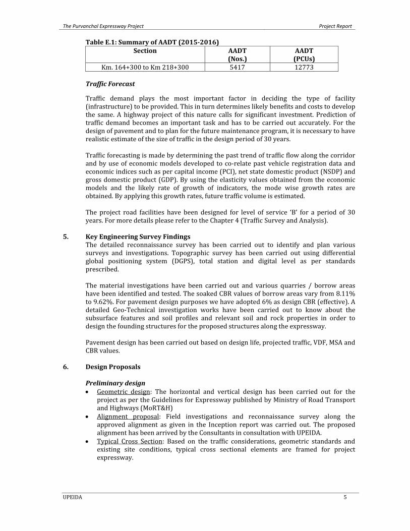
Table E.1: Summary of AADT (20152016) Section AADT
(Nos.) AADT (PCUs)
Km. 164+300 to Km 218+300 5417 12773
Traffic Forecast
Traffic demand plays the most important factor in deciding the type of facility (infrastructure) to be provided. This in turn determines likely benefits and costs to develop the same. A highway project of this nature calls for significant investment. Prediction of traffic demand becomes an important task and has to be carried out accurately. For the design of pavement and to plan for the future maintenance program, it is necessary to have realistic estimate of the size of traffic in the design period of 30 years. Traffic forecasting is made by determining the past trend of traffic flow along the corridor and by use of economic models developed to co‐relate past vehicle registration data and economic indices such as per capital income (PCI), net state domestic product (NSDP) and gross domestic product (GDP). By using the elasticity values obtained from the economic models and the likely rate of growth of indicators, the mode wise growth rates are obtained. By applying this growth rates, future traffic volume is estimated. The project road facilities have been designed for level of service ‘B’ for a period of 30 years. For more details please refer to the Chapter 4 (Traffic Survey and Analysis).
5. Key Engineering Survey Findings The detailed reconnaissance survey has been carried out to identify and plan various surveys and investigations. Topographic survey has been carried out using differential global positioning system (DGPS), total station and digital level as per standards prescribed. The material investigations have been carried out and various quarries / borrow areas have been identified and tested. The soaked CBR values of borrow areas vary from 8.11% to 9.62%. For pavement design purposes we have adopted 6% as design CBR (effective). A detailed Geo‐Technical investigation works have been carried out to know about the subsurface features and soil profiles and relevant soil and rock properties in order to design the founding structures for the proposed structures along the expressway. Pavement design has been carried out based on design life, projected traffic, VDF, MSA and CBR values.
6. Design Proposals Preliminary design • Geometric design: The horizontal and vertical design has been carried out for the
project as per the Guidelines for Expressway published by Ministry of Road Transport and Highways (MoRT&H)
• Alignment proposal: Field investigations and reconnaissance survey along the approved alignment as given in the Inception report was carried out. The proposed alignment has been arrived by the Consultants in consultation with UPEIDA.
• Typical Cross Section: Based on the traffic considerations, geometric standards and existing site conditions, typical cross sectional elements are framed for project expressway.
The Purvanchal Expressway Project Project Report
UPEIDA 6
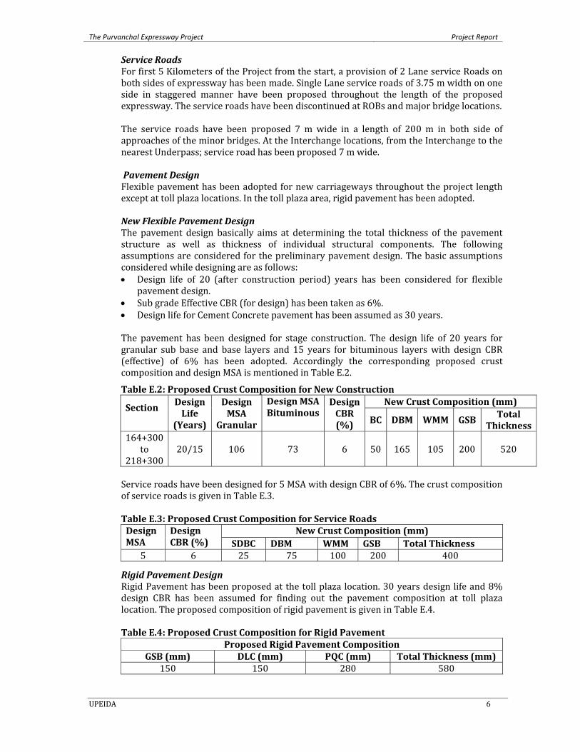
Service Roads For first 5 Kilometers of the Project from the start, a provision of 2 Lane service Roads on both sides of expressway has been made. Single Lane service roads of 3.75 m width on one side in staggered manner have been proposed throughout the length of the proposed expressway. The service roads have been discontinued at ROBs and major bridge locations. The service roads have been proposed 7 m wide in a length of 200 m in both side of approaches of the minor bridges. At the Interchange locations, from the Interchange to the nearest Underpass; service road has been proposed 7 m wide. Pavement Design Flexible pavement has been adopted for new carriageways throughout the project length except at toll plaza locations. In the toll plaza area, rigid pavement has been adopted. New Flexible Pavement Design The pavement design basically aims at determining the total thickness of the pavement structure as well as thickness of individual structural components. The following assumptions are considered for the preliminary pavement design. The basic assumptions considered while designing are as follows: • Design life of 20 (after construction period) years has been considered for flexible
pavement design. • Sub grade Effective CBR (for design) has been taken as 6%. • Design life for Cement Concrete pavement has been assumed as 30 years. The pavement has been designed for stage construction. The design life of 20 years for granular sub base and base layers and 15 years for bituminous layers with design CBR (effective) of 6% has been adopted. Accordingly the corresponding proposed crust composition and design MSA is mentioned in Table E.2.
Table E.2: Proposed Crust Composition for New Construction
Section
Design Life
(Years)
Design MSA
Granular
Design MSA Bituminous
Design CBR (%)
New Crust Composition (mm)
BC DBM WMM GSB Total Thickness
164+300 to
218+300 20/15 106 73 6 50 165 105 200 520
Service roads have been designed for 5 MSA with design CBR of 6%. The crust composition of service roads is given in Table E.3. Table E.3: Proposed Crust Composition for Service Roads Design MSA
Design CBR (%)
New Crust Composition (mm) SDBC DBM WMM GSB Total Thickness
5 6 25 75 100 200 400
Rigid Pavement Design Rigid Pavement has been proposed at the toll plaza location. 30 years design life and 8% design CBR has been assumed for finding out the pavement composition at toll plaza location. The proposed composition of rigid pavement is given in Table E.4. Table E.4: Proposed Crust Composition for Rigid Pavement
Proposed Rigid Pavement CompositionGSB (mm) DLC (mm) PQC (mm) Total Thickness (mm)
150 150 280 580
The Purvanchal Expressway Project Project Report
UPEIDA 7
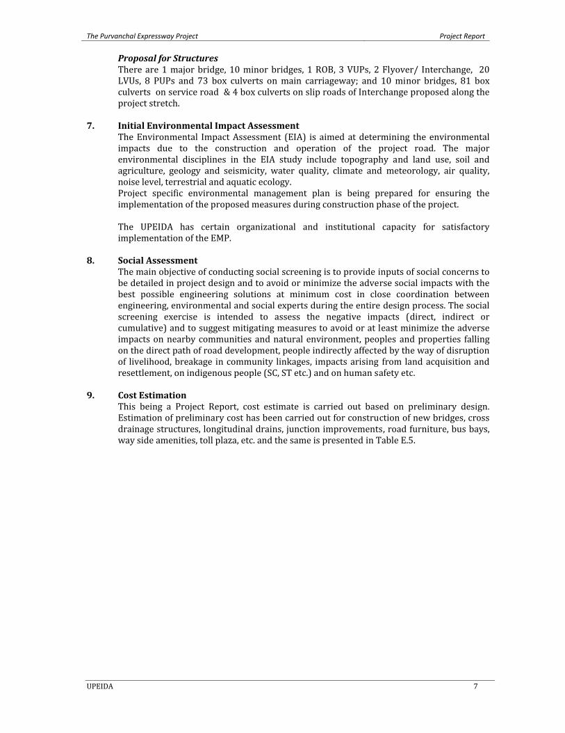
Proposal for Structures There are 1 major bridge, 10 minor bridges, 1 ROB, 3 VUPs, 2 Flyover/ Interchange, 20 LVUs, 8 PUPs and 73 box culverts on main carriageway; and 10 minor bridges, 81 box culverts on service road & 4 box culverts on slip roads of Interchange proposed along the project stretch.
7. Initial Environmental Impact Assessment The Environmental Impact Assessment (EIA) is aimed at determining the environmental impacts due to the construction and operation of the project road. The major environmental disciplines in the EIA study include topography and land use, soil and agriculture, geology and seismicity, water quality, climate and meteorology, air quality, noise level, terrestrial and aquatic ecology. Project specific environmental management plan is being prepared for ensuring the implementation of the proposed measures during construction phase of the project. The UPEIDA has certain organizational and institutional capacity for satisfactory implementation of the EMP.
8. Social Assessment The main objective of conducting social screening is to provide inputs of social concerns to be detailed in project design and to avoid or minimize the adverse social impacts with the best possible engineering solutions at minimum cost in close coordination between engineering, environmental and social experts during the entire design process. The social screening exercise is intended to assess the negative impacts (direct, indirect or cumulative) and to suggest mitigating measures to avoid or at least minimize the adverse impacts on nearby communities and natural environment, peoples and properties falling on the direct path of road development, people indirectly affected by the way of disruption of livelihood, breakage in community linkages, impacts arising from land acquisition and resettlement, on indigenous people (SC, ST etc.) and on human safety etc.
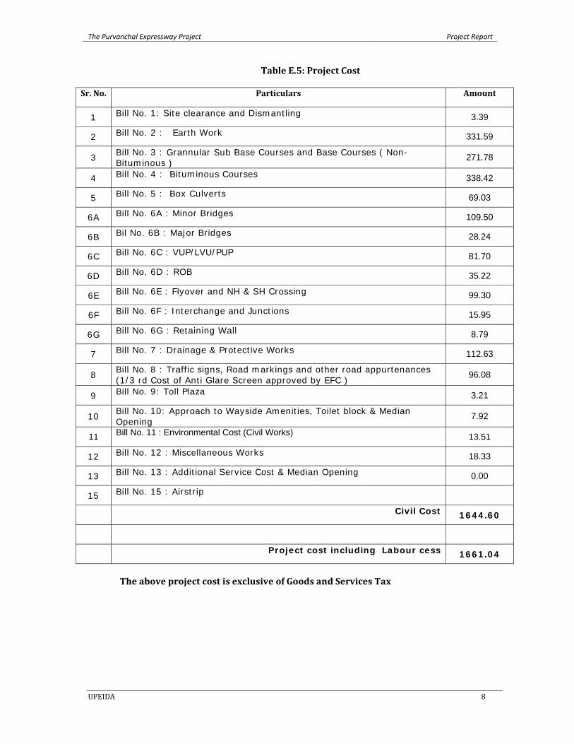
9. Cost Estimation This being a Project Report, cost estimate is carried out based on preliminary design. Estimation of preliminary cost has been carried out for construction of new bridges, cross drainage structures, longitudinal drains, junction improvements, road furniture, bus bays, way side amenities, toll plaza, etc. and the same is presented in Table E.5.
The Purvanchal Expressway Project Project Report
UPEIDA 8
Table E.5: Project Cost
Sr. No. Particulars Amount
1 Bill No. 1: Site clearance and Dismantling 3.39
2 Bill No. 2 : Earth Work 331.59
3 Bill No. 3 : Grannular Sub Base Courses and Base Courses ( Non- Bituminous )
271.78
4 Bill No. 4 : Bituminous Courses 338.42
5 Bill No. 5 : Box Culverts 69.03
6A Bill No. 6A : Minor Bridges 109.50
6B Bil No. 6B : Major Bridges 28.24
6C Bill No. 6C : VUP/LVU/PUP 81.70
6D Bill No. 6D : ROB 35.22
6E Bill No. 6E : Flyover and NH & SH Crossing 99.30
6F Bill No. 6F : Interchange and Junctions 15.95
6G Bill No. 6G : Retaining Wall 8.79
7 Bill No. 7 : Drainage & Protective Works 112.63
8 Bill No. 8 : Traffic signs, Road markings and other road appurtenances (1/3 rd Cost of Anti Glare Screen approved by EFC )
96.08
9 Bill No. 9: Toll Plaza 3.21
10 Bill No. 10: Approach to Wayside Amenities, Toilet block & Median Opening
7.92
11 Bill No. 11 : Environmental Cost (Civil Works) 13.51
12 Bill No. 12 : Miscellaneous Works 18.33
13 Bill No. 13 : Additional Service Cost & Median Opening 0.00
15 Bill No. 15 : Airstrip
Civil Cost 1644.60
Project cost including Labour cess 1661.04
The above project cost is exclusive of Goods and Services Tax
The Purvanchal Expressway Project Project Report
UPEIDA 9
Chapter1
DESCRIPTION OF PACKAGEV OF PURVANCHAL EXPRESSWAY
1 Introduction
This Main Report here pertains to the Package‐V of the Purvanchal Expressway.
1.1 PackageV from Sansarpur (Dist. Sultanpur) to Gobindpur (Dist. Azamgarh) (Km 164+300 to Km 218+300)
The stretch of green‐field alignment from Sansarpur (Dist. Sultanpur) to Gobindpur (Dist. Azamgarh) (Km 164+300 to Km 218+300) has been classified as Package‐V of the Purvanchal Expressway.
1.1.1 Terrain and Land Use The terrain of this stretch can be termed as plain and flat throughout.
1.1.2 Alignment The proposed alignment of the Expressway is a Greenfield alignment.
1.1.3 Major Intersections Proposed alignment intersects with 1 major road along the project stretch (Package‐V) across the following locations: • SH‐5 at Km 182+280 – Diamond Interchange – Slip roads with Toll booths.
1.1.4 Right of Way (ROW) ROW has been taken as 120m for the proposed expressway except at interchange locations, way side amenities, toilet block locations and at locations for training the course of nalah/drain, where the ROW varies.
1.1.5 Bridges and Cross Drainage Structures 1 major bridge, 10 minor bridges, 1 ROB, 3 VUPs, 2 Flyover/Interchange, 20 LVUs, 8 PUPs and 73 box culverts on main carriageway and 10 minor bridges, 81 box culverts on service road & 4 box culverts on slip roads of Interchange have been proposed along the project stretch. The detailed list of structures is given in Chapter 4 of this report.
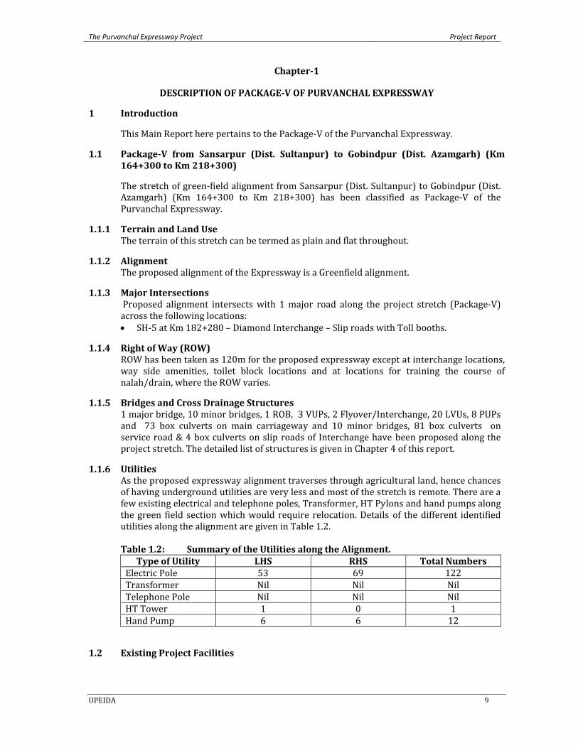
1.1.6 Utilities As the proposed expressway alignment traverses through agricultural land, hence chances of having underground utilities are very less and most of the stretch is remote. There are a few existing electrical and telephone poles, Transformer, HT Pylons and hand pumps along the green field section which would require relocation. Details of the different identified utilities along the alignment are given in Table 1.2.
Table 1.2: Summary of the Utilities along the Alignment.
Type of Utility LHS RHS Total NumbersElectric Pole 53 69 122 Transformer Nil Nil Nil Telephone Pole Nil Nil Nil HT Tower 1 0 1 Hand Pump 6 6 12
1.2 Existing Project Facilities

The Purvanchal Expressway Project Project Report
UPEIDA 10
Proposed Expressway alignment is a Green field alignment with majority length passing through agricultural/rural land; hence there are no existing facilities at present.
The Purvanchal Expressway Project Project Report
UPEIDA 11
Chapter2
METHODOLOGY & DESIGN STANDARDS
2 General
All the services are carried out strictly as per ToR. The Guidelines for Expressway published by Ministry of Road Trans‐port and Highways (MoRT&H) have been followed for preparing this Project Report. Specific Codes and Guidelines of the IRC and publications of the MoRT&H including circulars & general/special publications, technical Specifications & Standards have also been considered. All the field activities have been completed as discussed in detail with Authority. For Topographic survey latest electronic instruments like Differential Global Positioning System (DGPS), RTK GPS and Total Station were used. Data was collected as per formats and procedures approved by the MoRT&H and analyzed using in‐house developed software. MX Roads software for the highway designs and STADD‐proV8i for the structure designs are used. For the pavement designs standard software/programs developed in‐house have been used. In depth consultation process with UPEIDA was held on a regular basis to enhance the progress of the work. As time and quality are the essence of the project, before any analysis and designs, all the parameters to be used were got approved by the Client during preparation of draft reports so there is minimum changes later on, i.e. minimum time requirement in the finalization of final reports without compromising quality. The idea is to seek prior approval from client through meeting/discussion on Inception, alignment finalization, bid evaluation, pre‐bid conference etc. Similarly various traffic scenarios will be developed and presented to client for discussion and approval.
2.1 Design Basis The broad methodology has been developed keeping standard practices / IRC guidelines, with certain additions and modifications as felt necessary and as discussed with Uttar Pradesh Expressway and Industrial Development Authority (UPEIDA) during various re‐view meetings.
2.2 Review of Earlier Reports
The Consultants have collected and reviewed the relative study reports to have a better understanding of the project & also for getting some inputs as a part of the services. The study reports thus considered for review are: 1. Concept Report for Development of Agra–Lucknow Access Controlled Express‐way
(Green Field) Project. 2. Road development plan in the region by UPEIDA. 3. Master Plan reports within Project Influence Area especially for Agra and Lucknow
districts.
Any useful details relevant for the project available with the Client/ Other agencies have been collected. Other details are also collected and collated to form recommendations by considering the following inputs: • Material details • Soil Test results • Geo‐technical investigation reports • Topographic survey details / Bench mark details and other survey information • Utility Services/Utility Relocation Plans • Traffic Studies
The Purvanchal Expressway Project Project Report
UPEIDA 12
• Tree plantation records • Hydrological and Hydraulic details • Development Plans for major towns and areas along the project road • Availability of construction materials and unit rates for work items • Recent acquisition rates for different types of land/immovable properties • Right of Way Details from Revenue maps
2.3 SocioEconomic Profile
Socio‐economic profile of the influence area is prepared, after study of data on growth of population and density, human settlement pattern, land use, sub‐profiles of agriculture and industries, economic base, trends in socio‐economic indicators, development scenarios for various sectors, transport infrastructure and its uses such as use of waterways & rail trans‐port etc. The relevant data is collected from the following sources: • State Statistical Abstracts • State Year Books
Census Publications – Districts and State • Hand Books of Statistics of Districts in the area of influence • Economic Surveys of the State constituting the zone of influence • The Bureau of Economics & Statistics of Uttar Pradesh
2.4 Traffic Survey, Analysis and Projections Traffic surveys include (only those surveys would be carried out which are required for correctly forecasting the traffic along the proposed road): • Classified Traffic Volume Counts • Origin – Destination and commodity Movement Surveys
Standard procedures given in IRC Codes have been followed for carrying out Traffic Surveys. The data arrived from the Surveys has been analyzed to determine ADT of surrounding roads of the proposed project road and travel characteristics. Growth of traffic in project road influence area and also on the project road is regarded as the most important aspect since the whole project design is based on this. To establish the realistic growth rates, road transport data, population growth rates and socio‐economic parameters have been studied and analyzed. The growth rates for passenger vehicles have been worked out on the basis of annual growth rate of population and per capita income while the growth rates of freight vehicles have been based on the rate of growth in agricultural, industrial and tourism sectors and historical traffic data. These growth rates have been used to arrive at the traffic projections for the design period. After the development of project corridor to six lane standard configuration, greater amount of traffic is expected to be diverted from the peripheral road network. Appropriate traffic diversion models have been used for assessment of diverted traffic to this road. Details on traffic data & projections have been discussed in Chapter 5 of this Report.
2.5 Engineering Surveys and Investigations
2.5.1 Reconnaissance Survey of the Project Road
Reconnaissance survey has been carried out immediately before the kick off meeting to examine the general characteristics of the Project Corridor. Consultants have undertaken a site visit along with the experts in the field of Highway, Pavement and Bridge Engineering. This has helped in the detailed appreciation of the project corridor in terms of traffic and other engineering measures and judicious assessment of the following salient factors have generally been made:
The Purvanchal Expressway Project Project Report
UPEIDA 13
• Topography of the area • Terrain and soil conditions • Climate and Rainfall • Drainage Characteristics • Traffic patterns and preliminary identification of traffic homogeneous sections of road. • Railway lines and other critical utilities/services having impact on road alignment • Land use (agricultural, build‐up, forest land, etc.,) • Environmental factors • Availability of materials • Any other useful information
The findings are described in the following paragraphs;
2.5.2 Topographic Surveys Topographic survey has been carried out along the proposed alignment to know the topography, natural and manmade features present within the proposed ROW and to assess the existing geometric deficiencies along with land use plan. The survey has been carried out only after establishing horizontal and vertical control grids. Horizontal grid has been established through DGPS points and been erected at every 5 km interval. For vertical grid, bench mark has been erected at every 250m interval and connecting these to the nearest BM of Survey of India. Selection of primary Control Points and Observations is as detailed below:
• These are located on the edge of the proposed right of way (ROW) at inter‐visible locations at every 5 km.
• These are, as far as possible, on either side of 5 km stone so that it can be identified easily in the field and an arrow has been painted on the existing road indicating their location. They are recorded in separate field with their three dimensional locations.
• The stations selected are free from obstruction towards sky at an angle of 15° with horizontal plane.
• The horizontal control station is established on nail fixed in centre of RCC (M15) pillar of size 15 cm x 15 cm x 45 cm embedded in concrete M10 (5 cm all around) up to a depth of 30 cm and the balance 15 cm above the ground painted yellow.
• The Primary Control Stations are fixed using DGPS Trimble make instrument. The time of observations at Base Stations is observed for a minimum of 30 minutes and at Reference Stations for 20 minutes or longer if instrument signal is not indicating sufficient data received, to eliminate the possible projection and time errors in the signals received from various satellites being observed at respective locations in order to ensure high accuracy in the positioning of control stations within + 20 mm.
• Minimum of 6 satellites are available during observation to ensure high accuracy Secondary control stations are established at 2 km intervals using Total Station and through closed traverse distributed linearly running between two nearest Primary Control Stations ensuring accuracy in the order of 12√K in mm, where ‘K’ is the distance in kilometers between two primary control stations. Any errors within permissible limits are distributed in rational manner to establish the accurate and effective horizontal control grid. These are established on reference pillars having configuration similar to primary control station with an arrow painted on the surface of existing road indicating their location.
2.5.2.1 Pillar Construction Benchmark pillars at every 1000m along the route within the ROW have been constructed. All these pillars will have to be furnished with X, Y, Z co‐ordinates. The pillars are of size 150 x 150 x 600mm long. The pillar is concreted and embedded in a manner that 150mm is
The Purvanchal Expressway Project Project Report
UPEIDA 14
remain above ground. A steel rod has been fixed in the centre for punching the point and finally these are to be painted yellow.
2.5.2.2 Total Station Traverse A closed traverse is run for a loop length of 5 km. While traversing, station is established 200 to 250mts apart. The pillars constructed along the route are connected. These points are further used for detailed survey. The minimum accuracy of this survey is 1:10,000.
2.5.2.3 Bench mark These are located, as far as possible, along the proposed right of way (ROW) boundaries at an interval of 250 m with BM No. marked on it with red paint. • Bench Mark pillar is of size 15 cm x 15 cm x 45 cm cast in RCC M15 with a nail fixed in
the centre of the top surface and embedded in concrete M10 (5cm all around) up to a depth of 30 cm. The balance 15 cm above the ground is painted yellow.
• An arrow indicating the location of the BM is painted on the road with the permanent yellow paint and recorded in separate field books with its three dimensional location.
The Bench Mark is established using high accuracy Digital Level and Bar coded staff by way of double run leveling in small circuits of 3 km length ensuring an accuracy in the order of 12√k mm, where ‘K’ is the distance in Kilometers between two Bench Marks avail‐able in the project area, and error, if any, within permissible limits is distributed in rational manner to establish the accurate and effective vertical control grid.
The topographic survey has been extending up to the proposed Right of Way (ROW). Wherever necessary, the survey corridor width is further increased to accommodate situations arising out of encroachments and any other contingencies. The survey areas at the locations of intersections cover up to a minimum of 500m on the either side of the centre‐line and have sufficient width to accommodate improvement measures. Necessary surveys are also carried out for determining the requirements of service roads for local traffic, where appropriate.
2.5.2.4 Detailed Survey Using the horizontal and vertical control points established accurate data in the digital for‐mat in terms of Northing (Y). Easting (X) and Elevation (Z) co‐ordinates for all breaks in terrain such as ridges and ditches are collected perpendicular to the centre line at 50m intervals in tangent sections and 20‐25m in curve sections using Total Stations. Cross sections are taken for the specified corridor width of 110m; however this corridor width is increased to 150m on the inside of sharp curves to account for minor adjustments. All natural and man‐made features such as buildings, irrigation channels, drainage structures, temples, mosques, trees and utility installations etc. are captured during the survey. Spot level on the existing carriageway are captured at five points namely at centerline, mid points of both lanes of traffic movement and pavement edges at both ends to calculate the profile corrective courses more realistically. Trees with girth wise are captured with areas of plantation. Wherever there are groups of trees/plantations, they are picked with the areas of plantation. Boundaries of Agricultural Land area have been surveyed to demarcate the cultivation land limit. Where existing major roads cross the alignment, the survey has been extended to a maxi‐mum of 500m on either side of the road centerline to allow improvements including grade separated intersections to be designed. Apart from this, the survey has covered a maxi‐mum of 1000m and 500m on either side of centerline in cases of major and minor bridges respectively.
The Purvanchal Expressway Project Project Report
UPEIDA 15
2.5.2.5 Data Processing The field survey data are processed in the office to provide a digital output file for the de‐sign engineers. The data is structured so that the existing vertical profile along the pro‐posed alignment can be produced automatically. The format of the resulting data readily promotes the calculations of earthworks and other quantities required for the evaluation of cost estimates. Roadway plans have been produced from the survey data, which identify the available Right of Way (ROW) along the existing road corridors. In addition, the plans identify all existing utilities /installations within the corridor/ROW that require re‐location by the new road design. Action Plans for covering the relocation of these obstructing installations and public utilities are to be prepared on a km to km basis.
2.5.2.6 Material Investigations The Material Investigation for road construction has been carried out to identify the potential sources of construction materials and to assess their general availability, mechanical properties and quantities. This is one of the most important factors for stable, economic and successful implementation of the road program within the stipulated time for improvement work as well as for new carriageway, the list of materials includes the following: a) Granular material for lower sub‐base works. b) Crushed stone aggregates for upper sub‐base, base, surfacing and cement concrete
works. c) Sand for filter material and cement, concrete works, sub‐base and filling material. d) Borrow material for embankment, sub‐grade and filling. e) Manufactured material like cement, steel, bitumen, geo‐textiles etc. for other related
works.
The Information on material sources has been carried out with the following basic objectives:
• Source location, indicating places, kilometer age, availability and the status whether in
operation or new source. • Access to source, indicating the direction and nature of the access road i.e. left / right of
project road, approximate lead distance from the gravity centre and type of access road. • Ownership of land / quarries, either government or private. • Probable uses indicating the likely use of materials at various stages of construction
work i.e. fill materials, sub‐grade, sub‐base, base and wearing course and cross drainage structures.
During the process of investigation, due consideration has been given to the locally available materials for reducing the cost of construction. The samples have been collected as described below: • From quarry sites for aggregate characteristics like, aggregate impact value, gradation,
soundness, flakiness index and elongation, stripping value and water absorption etc. • From random pits (farmland) along the proposed alignment for availability of suitable
embankment and sub grade material, and identification of the borrow areas and tested in line with relevant IRC code.
2.5.2.7 Geotechnical Investigations Sufficient information about the arrangement & behavior of the underlying materials and their physical properties for adopting and designing the structural foundation is essential. Soil exploration through field investigation and laboratory testing of the substrata are helpful in arriving at required parameters for designing of safe and economical
The Purvanchal Expressway Project Project Report
UPEIDA 16
foundations. The data obtained from these investigations has been analyzed for safe design of the foundation. In the geotechnical report’s recommendations has been made for type of foundations and its safe bearing capacity/load carrying capacity required for the structure design.
2.5.2.8 Hydrological Investigations Hydrological investigations have been carried out for the entire project. It has been ensured that majority of the cross drainage structures are hierologically adequate to carry the discharge of the river / streams.
2.6 Traffic Design
2.6.1 General The capacity standards for expressway have been adopted as per the “Guidelines for Expressways”. Capacity analysis is fundamental to the planning, design and operation of roads and provides, among other things, the basis for determining the carriageway width to be provided at any point in a road network with respect to the volume and composition of traffic. Moreover it is a valuable tool for evaluation of the investments needed for future road constructions and improvements.
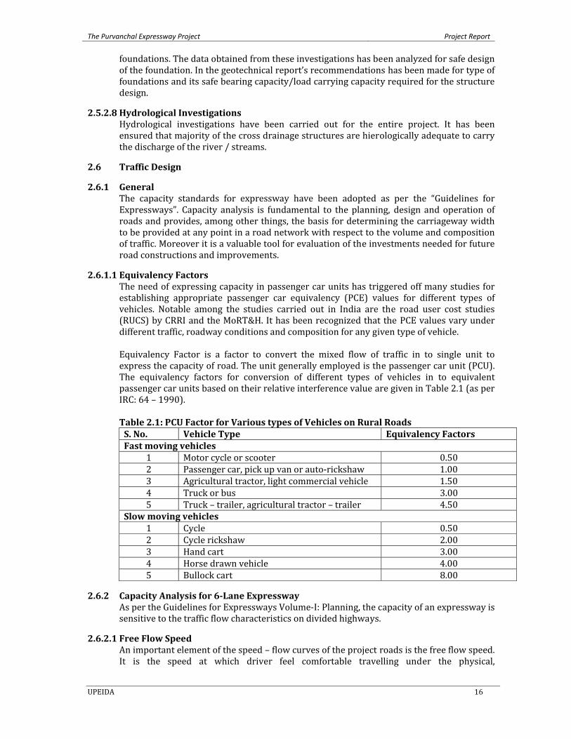
2.6.1.1 Equivalency Factors The need of expressing capacity in passenger car units has triggered off many studies for establishing appropriate passenger car equivalency (PCE) values for different types of vehicles. Notable among the studies carried out in India are the road user cost studies (RUCS) by CRRI and the MoRT&H. It has been recognized that the PCE values vary under different traffic, roadway conditions and composition for any given type of vehicle. Equivalency Factor is a factor to convert the mixed flow of traffic in to single unit to express the capacity of road. The unit generally employed is the passenger car unit (PCU). The equivalency factors for conversion of different types of vehicles in to equivalent passenger car units based on their relative interference value are given in Table 2.1 (as per IRC: 64 – 1990). Table 2.1: PCU Factor for Various types of Vehicles on Rural Roads S. No. Vehicle Type Equivalency Factors Fast moving vehicles
1 Motor cycle or scooter 0.50 2 Passenger car, pick up van or auto‐rickshaw 1.00 3 Agricultural tractor, light commercial vehicle 1.50 4 Truck or bus 3.00 5 Truck – trailer, agricultural tractor – trailer 4.50
Slow moving vehicles 1 Cycle 0.50 2 Cycle rickshaw 2.00 3 Hand cart 3.00 4 Horse drawn vehicle 4.00 5 Bullock cart 8.00
2.6.2 Capacity Analysis for 6Lane Expressway As per the Guidelines for Expressways Volume‐I: Planning, the capacity of an expressway is sensitive to the traffic flow characteristics on divided highways.
2.6.2.1 Free Flow Speed An important element of the speed – flow curves of the project roads is the free flow speed. It is the speed at which driver feel comfortable travelling under the physical,
The Purvanchal Expressway Project Project Report
UPEIDA 17
environmental and traffic control conditions on a non‐congested section of a multi lane highway, ‐ HCM (2000). All recent studies suggest that speed on project road is insensitive to flow over a broad range of flows. Thus free‐flow speed can be established on an existing facility by measuring in the field, the average speed of vehicles when flow rates do not exceed 1300 passenger car per hour per lane (PCPHPL) (HCM 1994). In the absence of traffic flow speed data on highway in India, the free flow speed is required to be assumed.
2.6.2.2 Factors affecting the Free Flow Speed (FFS):
The FFS of an expressway depends on the traffic and roadway conditions described below: • Lane width • Lateral Clearance • Number of Lanes • Interchange Density • Geometric design
The basic equation used to calculate the FFS is as given below:
FFS = BFFSfLWfLCfNfID Eq(1) Where, BFFS=base free flow speed, kmph fLW = adjustment factor for lane width fLC = adjustment factor for right shoulder lateral clearance fN = adjustment factor for number of lanes fID = adjustment factor for interchange density
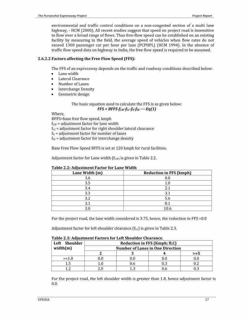
Base Free Flow Speed BFFS is set at 120 kmph for rural facilities. Adjustment factor for Lane width (fLW) is given in Table 2.2. Table 2.2: Adjustment Factor for Lane Width
Lane Width (m) Reduction in FFS (kmph) 3.6 0.03.5 1.03.4 2.13.3 3.13.2 5.63.1 8.13.0 10.6
For the project road, the lane width considered is 3.75, hence, the reduction in FFS =0.0 Adjustment factor for left shoulder clearance (fLC) is given in Table 2.3.
Table 2.3: Adjustment Factors for Left Shoulder Clearance. Left Shoulder width(m)
Reduction in FFS (Kmph; fLC) Number of Lanes in One Direction
2 3 4 >=5>=1.8 0.0 0.0 0.0 0.01.5 1.0 0.6 0.3 0.21.2 2.0 1.3 0.6 0.3
For the project road, the left shoulder width is greater than 1.8, hence adjustment factor is 0.0.
The Purvanchal Expressway Project Project Report
UPEIDA 18
Adjustment factor for Number of Lanes (fN): For rural facilities fN is set as 0. Adjustment factor for Interchange density (fID) Since the minimum interchange spacing more than 4 kms, the adjustment factor for interchange density is set as 0.
The using Equation (1) we get FFS=120‐0‐0‐0‐0 FFS = 120kmph
Calculation of Base Capacity (Base Cap) The base capacity (pcphpl) of an expressway facility is given by Base Capacity = 1700+10FFS; for FFS<=112 Eq(2) Base Capacity = 2400; for FFS>112 Eq(3) Since, the FFS is (120kmph)>112kmph, base capacity =2400pcphpl Determination of Peak Capacity (Peak Cap) The peak capacity is given by, Peak Cap = Base Cap*PHF*N*fHV*fP
Where, Peak Capacity = Peak capacity, vehicles per hour ( all lanes, one direction) PHF = Peak Hour Factor; 0 .88 so as to maintain LOS B always on Expressway N = Number of lanes in one direction (3 for 6‐lane); 3 for one direction flow on Expressway fHV = Adjustment factor for heavy vehicles; 0.8253 for expressway as calculated below fP = Adjustment factor for driver population; 0.975 for rural expressways
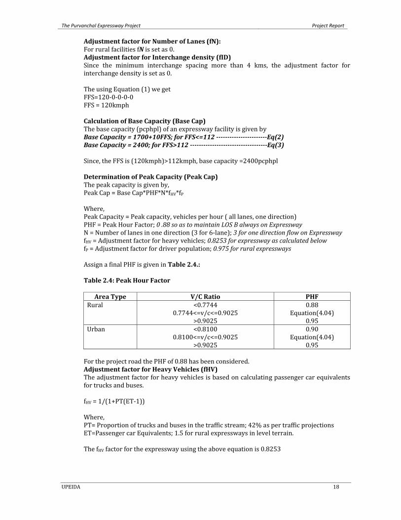
Assign a final PHF is given in Table 2.4.:
Table 2.4: Peak Hour Factor
Area Type V/C Ratio PHF
Rural <0.77440.7744<=v/c<=0.9025
>0.9025
0.88 Equation(4.04)
0.95 Urban <0.8100
0.8100<=v/c<=0.9025 >0.9025
0.90 Equation(4.04)
0.95
For the project road the PHF of 0.88 has been considered. Adjustment factor for Heavy Vehicles (fHV) The adjustment factor for heavy vehicles is based on calculating passenger car equivalents for trucks and buses.
fHV = 1/(1+PT(ET‐1)) Where, PT= Proportion of trucks and buses in the traffic stream; 42% as per traffic projections ET=Passenger car Equivalents; 1.5 for rural expressways in level terrain. The fHV factor for the expressway using the above equation is 0.8253
The Purvanchal Expressway Project Project Report
UPEIDA 19
Adjustment factor for Driver Population (fP) On rural expressways, the factor is set to 0.975 but has been considered as 1.0 for the project road.
Thus, the peak capacity for the 6‐lane expressway
Peak Capacity = 2400*0.88*3*0.8253*.975 = 5089 pcphpl (for 3lane in one direction)
= 5089*2/0.08 = 127225 PCUs per day (for 6lane carriageway with
depressed median) The peak capacity of the Purvanchal Expressway shall be 127225 PCUs per day
2.6.3 Recommended Design Service Volume for Six Lane Expressway
Assuming a V/C ratio of 0.77 lesser than 0.7744 corresponding to PHF of 0.88 to maintain a Level of Service B, the Design Service Volume for 6‐Lane Expressway with depressed median shall be 98000 PCU per day for peak hour flow of 8%
= 127225 * 0.77 = 97963, say 98000 PCUs per day
2.7 Engineering Design
2.7.1 Geometric Design of the Alignment The Preliminary Design has been carried out on the selected alignment so as to have optimum Construction, Operation & maintenance cost and Vehicle Operation Cost; minimum Social Impacts and Social Costs and Environmental Impacts and Environmental Mitigation Costs. The preferred alignment would definitely have minimum Rehabilitation and Resettlement i.e. it would utilize to the maximum possible barren / agriculture / government land to minimize Land Acquisition in villages / habited areas. A thorough consultation with stakeholders including industries, relevant government agencies, NGOs, project affected persons (including farmers & people having property) and other consultants working in the region will be made.
Geometric Design Control The detailed design for geometric elements covers, but is not limited to the following major aspects: • Horizontal alignment • Longitudinal profile • Cross‐sectional elements • Junctions, intersections and Interchanges • Service road along the alignment
Different options for providing grade separated interchanges were examined and the geometric design of interchanges has taken into account the site conditions, turning movement characteristics, level of service, overall economy and operational safety. Indicative Design Standards The indicative design standards for geometric design of road are illustrated in Table 2.5 for main carriageway, geometric standards for Interchange elements and Length of speed
The Purvanchal Expressway Project Project Report
UPEIDA 20
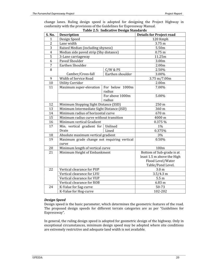
change lanes. Ruling design speed is adopted for designing the Project Highway in conformity with the provisions of the Guidelines for Expressway Manual.
Table 2.5: Indicative Design Standards S. No. Description Details for Project road 1 Design Speed 120 Kmph 2 Lane width 3.75 m 3 Raised Median (including shyness) 5.50m 4 Median side paved strip (Shy distance) 0.75 m 5 3‐Lane carriageway 11.25m 6 Paved Shoulder 3.00m 7 Earthen Shoulder 2.00m 8
Camber/Cross‐fall C/W & PS 2.50%
Earthen shoulder 3.00% 9 Width of Service Road 3.75 m/7.00m10 Utility Corridor 2.00m 11 Maximum super‐elevation For below 1000m
radius 7.00%
For above 1000m radius
5.00%
12 Minimum Stopping Sight Distance (SSD) 250 m 13 Minimum Intermediate Sight Distance (ISD) 360 m 14 Minimum radius of horizontal curve 670 m 15 Minimum radius curve without transition 4000 m 16 Minimum vertical Gradient 0.375 % 17 Min. vertical gradient for
Drain Unlined 1% Lined 0.375%
18 Absolute maximum vertical gradient 3% 19 Maximum grade change not requiring vertical
curve 0.50%
20 Minimum length of vertical curve 100m 21 Minimum Height of Embankment Bottom of Sub‐grade is at
least 1.5 m above the High Flood Level/Water Table/Pond Level.
22 Vertical clearance for PUP 3.0 m Vertical clearance for LVU 3.5/4.3 m Vertical clearance for VUP 5.5 m Vertical clearance for ROB 6.83 m
24 K‐Value for Sag‐curve 50‐73 K‐Value for Hog‐curve 102‐202
Design Speed Design speed is the basic parameter, which determines the geometric features of the road. The proposed design speeds for different terrain categories are as per “Guidelines for Expressway”. In general, the ruling design speed is adopted for geometric design of the highway. Only in exceptional circumstances, minimum design speed may be adopted where site conditions are extremely restrictive and adequate land width is not available.
The Purvanchal Expressway Project Project Report
UPEIDA 21
2.7.2 Cross Sectional Elements
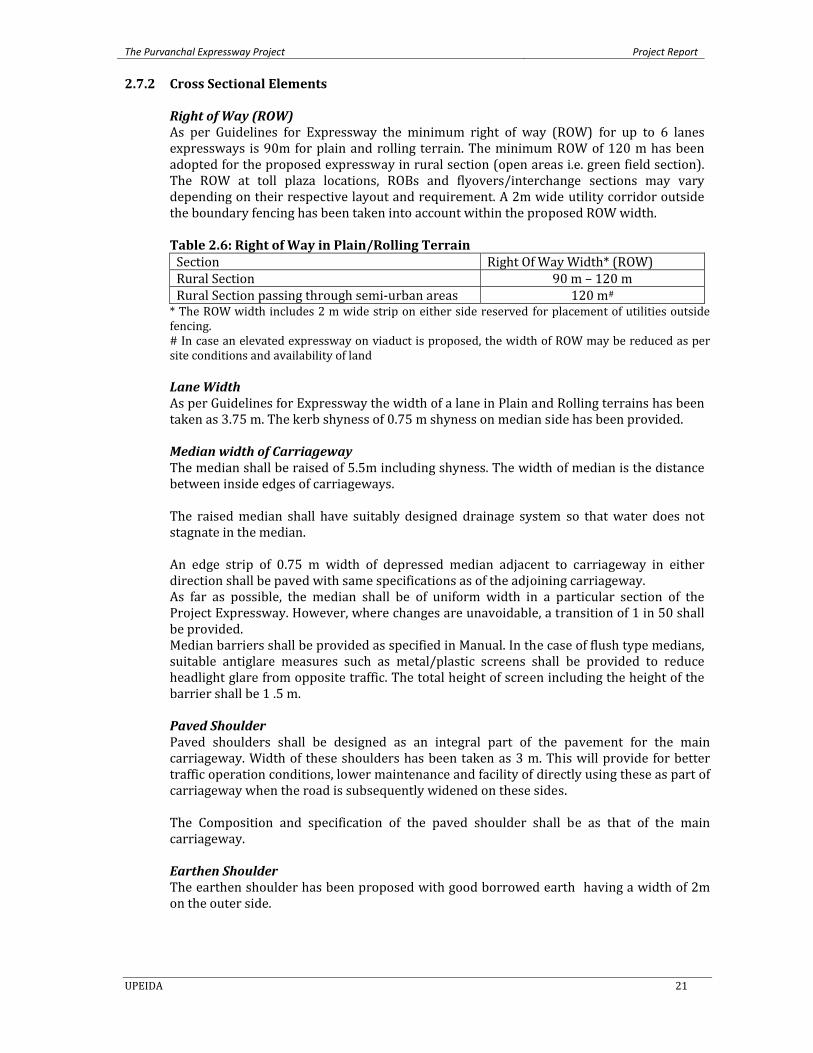
Right of Way (ROW) As per Guidelines for Expressway the minimum right of way (ROW) for up to 6 lanes expressways is 90m for plain and rolling terrain. The minimum ROW of 120 m has been adopted for the proposed expressway in rural section (open areas i.e. green field section). The ROW at toll plaza locations, ROBs and flyovers/interchange sections may vary depending on their respective layout and requirement. A 2m wide utility corridor outside the boundary fencing has been taken into account within the proposed ROW width.
Table 2.6: Right of Way in Plain/Rolling Terrain Section Right Of Way Width* (ROW) Rural Section 90 m – 120 m Rural Section passing through semi‐urban areas 120 m# * The ROW width includes 2 m wide strip on either side reserved for placement of utilities outside fencing. # In case an elevated expressway on viaduct is proposed, the width of ROW may be reduced as per site conditions and availability of land
Lane Width As per Guidelines for Expressway the width of a lane in Plain and Rolling terrains has been taken as 3.75 m. The kerb shyness of 0.75 m shyness on median side has been provided.
Median width of Carriageway The median shall be raised of 5.5m including shyness. The width of median is the distance between inside edges of carriageways.
The raised median shall have suitably designed drainage system so that water does not stagnate in the median. An edge strip of 0.75 m width of depressed median adjacent to carriageway in either direction shall be paved with same specifications as of the adjoining carriageway. As far as possible, the median shall be of uniform width in a particular section of the Project Expressway. However, where changes are unavoidable, a transition of 1 in 50 shall be provided. Median barriers shall be provided as specified in Manual. In the case of flush type medians, suitable antiglare measures such as metal/plastic screens shall be provided to reduce headlight glare from opposite traffic. The total height of screen including the height of the barrier shall be 1 .5 m. Paved Shoulder Paved shoulders shall be designed as an integral part of the pavement for the main carriageway. Width of these shoulders has been taken as 3 m. This will provide for better traffic operation conditions, lower maintenance and facility of directly using these as part of carriageway when the road is subsequently widened on these sides. The Composition and specification of the paved shoulder shall be as that of the main carriageway. Earthen Shoulder The earthen shoulder has been proposed with good borrowed earth having a width of 2m on the outer side.
The Purvanchal Expressway Project Project Report
UPEIDA 22
Sight Distance The Safe stopping sight distance and desirable minimum sight distance for divided carriageway for various design speed given in Table 2.8. The desirable values of the sight distance shall be adopted unless there are sight constraints. A minimum of Safe stopping sight distance shall be available throughout. Table 2.8: Safe Sight Distance Design Speed (km/hr)
Safe Stopping Sight Distance (m)
Desirable minimum Sight Distance (m) ( Intermediate Sight Distance)
120 250 500 100 180 360
At critical locations decision or decision points where changes in cross sections occurs such as Toll Plazas and Interchanges, the sight distance shall be not be less than decision sight distance given in Table 2.9. The criteria for measuring sight distance are same as for the stopping sight distance.
Table 2.9: Decision of Sight Distance Design Speed (km/hr) Decision Sight Distance (m)
120 360100 315
Horizontal Alignment The horizontal curves on the project road are designed for maximum radii (where feasible) as per Guidelines of Expressway manual and IRC:SP:99‐2013, absolute minimum radius has been used at couple of locations. The Alignment shall be fluent and blend with the topography. The horizontal curve shall be designed to have largest practical radius and shall consist of circular portion flanked by spiral transitions at both the ends.
Super – Elevation Super‐Elevation shall be limited to 7%, if radius of curve is less than desirable minimum radius. It shall be limited to 5% if radius is more than or equal to desirable minimum. Super elevation shall be not be less than the minimum specified Cross fall. The super elevation at curves is arrived at as per the following equation: (e + f) = v2/127R Where, v = Vehicle speed in Km/hr. e = Super elevation ratio in meter per meter f = Coefficient of side friction between vehicle tyre and pavement (0.1) R = Radius in meters. The super elevation is calculated keeping in view the horizontal radii and gradient at curves at different locations.
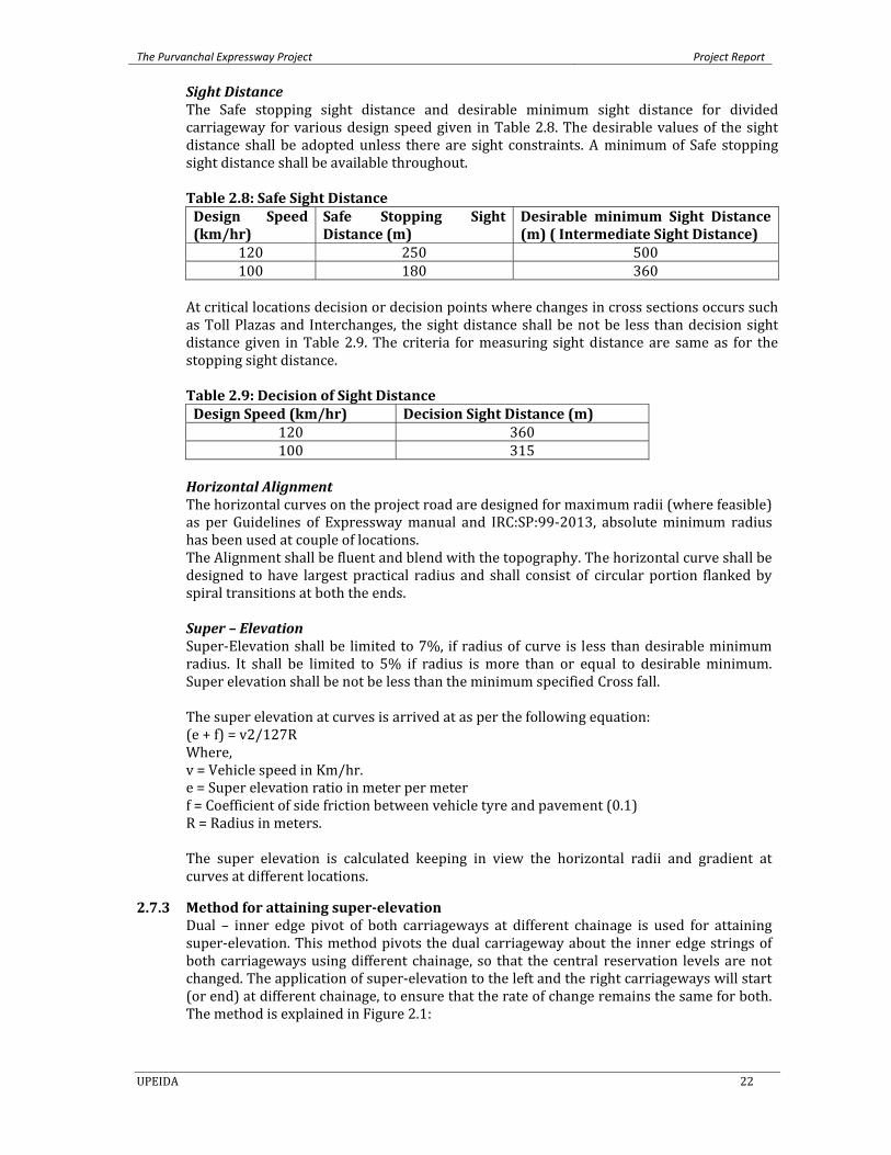
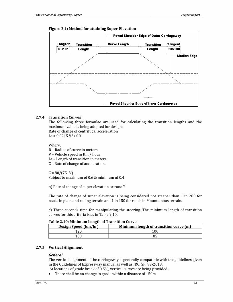
2.7.3 Method for attaining superelevation Dual – inner edge pivot of both carriageways at different chainage is used for attaining super‐elevation. This method pivots the dual carriageway about the inner edge strings of both carriageways using different chainage, so that the central reservation levels are not changed. The application of super‐elevation to the left and the right carriageways will start (or end) at different chainage, to ensure that the rate of change remains the same for both. The method is explained in Figure 2.1:
The Purvanchal Expressway Project Project Report
UPEIDA 23
Figure 2.1: Method for attaining SuperElevation
2.7.4 Transition Curves The following three formulae are used for calculating the transition lengths and the maximum value is being adopted for design: Rate of change of centrifugal acceleration Ls = 0.0215 V3/ CR Where, R – Radius of curve in meters V – Vehicle speed in Km / hour Ls – Length of transition in meters C – Rate of change of acceleration. C = 80/(75+V) Subject to maximum of 0.6 & minimum of 0.4 b) Rate of change of super elevation or runoff. The rate of change of super elevation is being considered not steeper than 1 in 200 for roads in plain and rolling terrain and 1 in 150 for roads in Mountainous terrain. c) Three seconds time for manipulating the steering. The minimum length of transition curves for this criteria is as in Table 2.10.
Table 2.10: Minimum Length of Transition Curve Design Speed (km/hr) Minimum length of transition curve (m)
120 100100 85
2.7.5 Vertical Alignment
General The vertical alignment of the carriageway is generally compatible with the guidelines given in the Guidelines of Expressway manual as well as IRC: SP: 99‐2013. At locations of grade break of 0.5%, vertical curves are being provided. • There shall be no change in grade within a distance of 150m
The Purvanchal Expressway Project Project Report
UPEIDA 24
• The length of vertical curve will not be less than 0.6V (kmph) • Number of vertical intersection point shall not be more than 4 per km. • At locations of sight deficiency, at least stopping sight distance (SSD) is being provided.
The aspect of efficient drainage shall be kept into consideration while designing the vertical profile and cross sections of the Project Expressway as stipulated in IRC:SP:42 and IRC:SP:50. The vertical alignment shall be coordinated with the horizontal alignment
Gradients The ruling and limiting gradients are given in Table 2.11.
Table 2.11: Gradients Terrain Ruling Gradient Limiting Gradient Plain 2.5% 3.0%Rolling 3.0% 4.0%
The ruling gradient shall be adopted as far as possible. Limiting gradient shall be adopted only in very difficult situation and for short lengths. In cut sections, minimum gradient for drainage considerations is 0.5% (1 in 200) if the side drains are lined; and 1.0% (1 in 100) if these are unlined.
Vertical Curves Long sweeping vertical curves shall be provided at all grade changes. Summit curves and valley curves shall be designed as square parabolas. The length of the vertical curves is controlled by sight distance requirements, but desirably curves with the longer length shall be provided from aesthetic considerations. The minimum grade changes requiring vertical curve and the minimum length of vertical curve shall be as given in Table 2.12. More liberal values are adopted wherever this is economically feasible. Valley curves are designed for headlight sight distance. Table 2.12: Minimum Length of Transition Curve Design Speed (km/hr)
Minimum Grade Change requiring Vertical curve
Minimum length of Vertical Curve(m)
120 0.5% 100 100 0.5% 85
Lateral and Vertical Clearance at Underpasses Lateral Clearance Minimum clearance at under passes shall be as follows: i) For Vehicular Underpass, the lateral clearance shall not be less than 12m (7m
carriageway + 2X2.5 m Shoulder width on either side). ii) For Light Vehicular Underpass, the lateral clearance shall not be less than 10.5m
including 1.5m wide raised footpaths on either side. iii) For Pedestrian and Cattle Underpasses the lateral clearance shall not be less than
7m. iv) Crash barrier shall be provided for protection of vehicles from colliding with
abutments and piers and the deck of the super structures.
Vertical Clearance The vertical clearances at underpasses shall not be less than the values given in Table 2.13. Table 2.13: Vertical Clearance Vehicular Underpass 5.5mLight Vehicular Underpass 4.3m / 3.5mPedestrian, Cattle Underpass 3.0m
The Purvanchal Expressway Project Project Report
UPEIDA 25
Lateral and Vertical Clearance at Overpasses
Lateral Clearance Shall be provided as a full roadway width as specified in Schedule of Contract Agreement.
Vertical Clearance A minimum of 5.5m Vertical Clearance shall be provided from all points of the Carriageway of the Project Expressway.
2.7.6 CrossFall The crossfall on each sections of the expressway carriageway shall be as given in Table 2.14. Each carriageway shall have unidirectional cross fall.
Table 2.14: Crossfall on different surfaces CrossSectional Element Annual Rainfall Carriageway, Paved shoulders, Edge Strip, Flush Median.
1000mm or more Less than 1000mm 2.5 % 2.0 %
The crossfall for earthen/granular shoulders on straight portions shall be at least 0.5% steeper than the values given in Table above. On Super Elevated sections, the earthen portion of the shoulder on the outer side of the curve would be provided with reverse crossfall so that the earth does not drain on the carriageway and the storm water drains out with minimum travel path.
2.8 Design OF Horizontal and Vertical Alignment The general principles and design criteria laid down in MoRTH Guidelines for Expressways shall be followed except as otherwise indicated in this Manual.
Culverts The culverts are proposed to be built to the full formation width of the road and have been designed accordingly. Highway Signs and Marking The road signs conforming to latest IRC: 67 have been proposed. Location of route marker signs are as per the latest IRC: 2; the provision for hectometer stones, 5th kilometer stone, Kilometer and 200 m stones are as per latest IRC: 8 and latest IRC: 26 respectively. The boundary stones are as per latest IRC: 25. Road Delineators are as per latest IRC: 79. All road signs are considered as retro‐reflective sheet of high intensity grade with encapsulated lens fixed over aluminium substratum and conforming to MoRT&H Specifications for road and bridge works. Provisions for Road markings have been considered as latest IRC: 35.
2.9 Access Control Project Expressway shall be designed for fast motorized traffic with full control of access. Access to the Expressway shall be provided with grade separators at location of intersections. Parking/standing, loading/unloading of goods and passengers and pedestrians/animals shall not be permitted on the Expressway. Location of interchange – The locations of individual interchanges are determined primarily to reduce detour considering regional network and nearness to places of importance. Location of interchange is guided by the following situations:
The Purvanchal Expressway Project Project Report
UPEIDA 26
i) At crossing or nearest points of other Expressways, National Highways, State Highways and important arterial roads.
ii) At crossing or nearest points of major roads to important ports, airports, material transport facilities, commercial and industrial areas, and places of tourist interest.
The interchanges shall be provided at the locations specified in Schedule‐B of the Contract Agreement.
2.10 Connecting roads Connecting roads where required to maintain proper circulation of local traffic, continuity of travel and to facilitate crossing over to the other side of the Project Expressway through an under/overpass shall be constructed on the land acquired within the ROW of the Project Expressway. These shall be provided outside the fencing. The location, length, other details and specifications of connecting roads, to be constructed by the shall be specified in Schedule‐B of the Contract Agreement. The width of the connecting road shall be 7.0 m. The construction and maintenance of connecting roads shall be part of the Project Expressway
2.11 Pavement Design Type of Pavement – The Authority may require provision of specific type (flexible/rigid) of pavement depending upon specific site conditions. Such requirements shall be as specified in Schedule‐B of the Contract Agreement. Unless otherwise specified in Schedule‐B, the may adopt any type (flexible/rigid) of pavement structure for new construction. Flexible pavement is designed by using IRC: 37‐2012 and rigid pavement is designed as per the provisions contained in latest IRC: 58. Besides the above, designs for service roads, toll plaza, parking bays have been carried out.
Design of flexible pavement – The pavement shall be designed to ensure the specified performance for the projected traffic needs, climate and type of soils in the given area. The Contractor is expected to use a design procedure that is appropriate to produce a cost‐effective structure meeting the performance requirements and long term durability. The Contractor may use IRC:37 “Tentative Guidelines for the Design of Flexible Pavements” or it may use any internationally accepted design procedure that is based on past performance and research. It will be the Contractor’s responsibility to provide a pavement structure that fully meets the prescribed performance requirements throughout the operation period. Design of rigid pavement – Jointed rigid pavement shall be designed in accordance with the method prescribed in IRC:58 “Guidelines for the Design of Plain Jointed Rigid Pavements for Highways”. Continuously Reinforced Concrete Pavements (CRCP) shall be designed as per any recognised international guidelines which shall be subject to approval by the Independent Engineer.
Design Life The bituminous pavement with design life of 15 years has been considered for the flexible pavement design. For rigid pavement a design life of 30 years has been considered.
Design Traffic The Design traffic has been estimated in terms of cumulative number of standard axles (8160kgs) to be carried by the Pavement during the design period.
Any likely change in traffic due to proposed improvement of the facility and/or future development plans, land use, shall be duly considered in estimating the Design Traffic. The Growth rates mentioned in the Traffic Studies chapter has been considered while calculating the Million Standard Axle loads. The project road is a green field highway and there is no existing carriageway, therefore, the VDF has been calculated based on the Axle
The Purvanchal Expressway Project Project Report
UPEIDA 27
Load Surveys conducted on alternate roads and the values of VDF has been presented in Section 3.3.3 of this report. Rigid Pavement Design
Design of Concrete Slab
Once the parameters are decided, actual stresses developed in the concrete slab due to design wheel load is computed by the Westergaard’s Equation modified by Teller and Sutherland. The maximum stress occurs in the corner and the minimum in the interior. The edge load condition gives an intermediate value.
Temperature stresses at the edge are calculated by using Bradbury’s formula. The temperature stresses in the corner region is negligible as the corners are relatively free to wrap and may be ignored. The design wheel load stress and the temperature stress at the edge are then added up together and this summation shall be less than 28 days flexural strength of concrete for the assumed thickness to be adequate from design point of view. Once the assumed slab thickness is found adequate for the combined stresses developed due to temperature and design wheel load, its adequacy needs to be checked from the view point of its consumption of fatigue resistance. In this case also, edge stresses are computed as discussed earlier for various axle load classes. Then stress ratio (SR) is calculated as ratio of stress due to wheel load and the 28 days flexural strength of concrete for all axle load class. Consumption of fatigue resistance is computed for this stress ratio for each axle load class. Summation of this consumption of fatigue resistance should not exceed the allowable limit for the assumed thickness to be adequate from the view point of fatigue consideration. Design of Joints
Once the concrete slab thickness is designed based on particular spacing and location of joints, the remaining job is the design of dowel bars and tie bars with the provision of adequate sealants.
Dowel Bars The design of dowel bar at joints is carried out on the basis of its load transfer capacity. It is recommended that 40% of wheel load can be transferred through dowel bar system. It is observed that failure of dowel bar occurs due to the crushing of concrete below the dowel bar and hence bearing stress shall be considered for its design. Generally 500 mm long 32 mm diameter M.S. bar at a spacing of 250 – 300 mm is used as dowel bar for concrete slab of 200 ‐350 mm thick. No dowel bar is required for slab thickness less than 150 mm. However separate calculation has been made for present situation for dowel bar design. Tie Bar Tie bars are provided to prevent the adjoining slabs from separating. Longitudinal joints are provided with tie bars. It does not increase the structural capacity of the slab and are not designed as load transferred devices.
2.12 Hydrological Design Design Standards The hydrological & hydraulic design for cross drainage structure shall conform to the fol‐lowing codes and reports: IRC: SP‐13 – Guidelines for the design of small bridges and culverts IRC: 5 – Code of practice for Road Bridges, Section I (General features of Design)
The Purvanchal Expressway Project Project Report
UPEIDA 28
IRC: 78 – Code of Practice for Road Bridges, Section VII (Design of Foundation and Substructure) IRC: SP‐87 – Manual of Specifications and Standards for Six‐Laning of Highways through Public Private Partnership
Design Approach The hydrological & hydraulic design of bridges is an important aspect to determine the minimum required waterway; design highest flood level (HFL) and minimum scour levels of piers & abutments of the bridges proposed on the new alignments. The various design standards (latest) which have been adopted for the hydrological & hydraulic design of bridges are given below. Approach slabs shall be provided for all bridges and grade separated structures as per Clause 217 of IRC:6 and Section 2700 of MORTH Specifications.
Design Parameters – Area of catchment & length of longest stream have been obtained from topographical sheets of Survey of India (SOI). The Cross Section of stream at 500 m U/S and 500 m D/S depending upon catchment area along with longitudinal gradient has been obtained to evaluate design discharge .The various method such as area velocity , unit hydrograph Rankins method has been considered for obtaining of design discharge .
Scour Depth Scour depth can be calculated as per Clause 703.2 of latest IRC: 78 and as explained in latest IRC: SP 13. The mean depth of scour, dsm below the highest flood level is given by the following equation: dsm = 1.34 (Db2/Ksf)1/3 Where, Db = the design discharge for foundation in cumec per meter width. The value of Db shall be the total design discharge divided by the effective linear waterway width be‐tween abutments. “Silt Factor” (Ksf) have been assumed based on the silt factor values of the Agra to Etawah project. As per latest IRC: 78, for the design of piers and abutments located in a straight reach and having individual foundations without any floor protection works, the maximum depth of scour from the highest flood level is given by: For piers: dmax = 2 x dsm For abutments: dmax = 1.27 x dsm (having retained approach) Minimum Founding Level: The foundation has been taken to a level to safeguard against scour. In case of bridges, where the mean scour depth dsm is calculated by using the equation given in Clause 703.2 of latest IRC‐78, the depth of foundation has not been taken less than that of existing structures in the vicinity.
2.12.1 Drainage and Protection Works The drainage requirements for the project road and adjoining areas are assessed through the DTM prepared from topographical survey data. Pavement internal and external drain‐age is ensured by providing drainage layer and camber respectively. Longitudinal slopes in roadside ditches and central drain are generally equal to generate self cleaning velocity at the time of storm. Small catchment analysis with project specific unit hydrograph is undertaken for the hydraulic design of the drain channel. The shape of the channels is fixed to facilitate easy and economical construction and easy maintenance. Suitable drainage system is planned for the high embankment, super‐elevated carriageway and other key areas, with a view to
The Purvanchal Expressway Project Project Report
UPEIDA 29
en sure easy collection and disposal of storm water. A network has been conceptualized from runoff till final disposal and its continuity is ensured at each critical point.
2.13 Structural Design
2.13.1 General This section deals with the standards to be adopted in design of vis‐à‐vis ROBs, flyovers, bridges, underpasses and culverts. It also provides for the type of materials and their specifications that had been adopted for the above structures, the loads and forces to be considered. The project road is 6 lane and the structures are also designed for 6 lanes.
2.13.2 Crosssectional Elements a) Structural width for bridges / flyovers / road over rail bridges
The overall deck width for all bridges, underpasses & ROBs has been kept same 21.25 m (including 0.5m crash barrier on either side) in each direction of traffic. Please refer for structure drawing and GADs of each major/minor structures.
b) Median width A median width of 3.0 m is maintained between two outer faces of RCC crash barriers.
c) Reinforced Earth Retaining Structures – The design and construction of reinforced earth structures shall conform to section 3100 of MORTH Specifications. Reinforced earth retaining structures shall not be provided near water bodies. Such structures should be given special attention in design, construction, ground improvement where necessary, maintenance and selection of System/System design. Local and global stability of the structure shall be ensured.
d) Road over bridge (road over railway line) i) If the alignment of road at the existing railway crossing has skew angle more
than 45°, the alignment of road or of pier/abutment shall be suitably designed to reduce skew angle up to 45°.
ii) Railways normally do not allow construction of solid embankment in their right of way. The horizontal and vertical clearances to be provided on the railway land shall be as per requirement of the Railway authorities.
iii) In case the Authority has obtained approval of General Arrangement Drawings, the same shall be appended with the Request for Proposal. The Contractor shall have option of adopting the same span arrangement or have his revised proposal for GAD approved from the Railways. In case the total length of stilt portion is not reduced, it will not be considered as change of scope. However, before submitting the revised proposal to the Railways, prior consent of the Authority shall be required.
iv) The Contractor shall be required to obtain approvals of all designs and drawings from the concerned Railway authorities.
v) The construction of ROB within the railway boundary shall be under the supervision of the Railway authorities.
vi) The approach gradient shall not be steeper than 1 in 40. vii) Outside the railway boundary, one span of 12 m conforming to the
requirements of Vehicular Underpass shall be provided on either side of ROB to cater for the local traffic, inspection, and pedestrian movement.
2.13.3 Specification for Material
a) Concrete: The grades of concrete are either equal to or higher than those pre‐scribed in latest IRC: 112. Grade of concrete in various structural elements is for moderate conditions of exposure.
The Purvanchal Expressway Project Project Report
UPEIDA 30
Superstructure PSC Members : M 45 RCC T‐Girder and Deck Slab : M 35 RCC Solid Slab : M 35 RCC Box cell : M 35 RCC Crash Barriers: M 40 Substructure RCC substructures and foundations: M 35 All PCC structural members: M 20 All PCC non structural members: M 15 Pedestals for bearings Pot/PTFE : M 40 Elastomeric: M 40
b) Steel: This conforms to the provisions given in IS: 1786, IS: 432 (Part I).
Reinforcement steel: • High yield strength deformed bars conforming to Fe 500 / TMT. • Mild steel not to be used. • Pre‐stressing steel These conform to IS: 14268‐1995 System : 19 K13 or 12 T13 low relaxation multiple strands system Cables :19 K13 or 12 T13 systems with strands of 12.7 mm nominal diameters. Sheathing : 90 mm / 75mm Corrugated HDPE sheathing duct.
c) Bearings
All bearings shall be easily accessible for inspection, maintenance and replacement. Suitable permanent arrangements shall be made for inspection of bearings from bridge deck. Design and specifications of bearings shall be as per IRC:83 (Part I, II and III). Spherical bearings shall conform to the requirements of BS:5400 and materials of such bearings may conform to the relevant BIS codes nearest to the specifications given in BS:5400. The drawing of bearings shall include the layout plan showing exact location on top of pier and abutment cap and the type of bearings i.e. fixed/free/rotational at each location along with notes for proper installation. The bearing should cater for rotation and movement in both longitudinal and lateral direction. Elastomeric bearing has been provided under RCC T‐beams and RCC solid slabs type superstructures as per latest IRC: 83 (Part II) and shall conform to clause 2005 of MoRT&H specification for Road and Bridge Works.
POT cum PTFE bearing has been provided for span more than 25m where we have to cater for large loads and conforming to latest IRC: 83 (Part III) and clause 2006 of MoRT&H specifications for Road & Bridge works.
d) Expansion Joints
All Structures shall have minimum number of expansion joints. This may be achieved by adopting longer spans, making the superstructure continuous or by adopting integrated structures. Expansion joints shall conform to IRC:SP:69. In any case, the number of expansion joints shall not be more than 1 for each 100 m length of the bridge or part thereof. For avoidance of doubt, the structures upto 100 m length shall have only one joint at one side abutment, the structures over 100 m and upto 200 m length may have two joints and structures over 200 m and upto 300 m length may have maximum 3 expansion joints. Elastomeric strip seal type expansion joints are provided on all the bridges and ROBs as per Clause No. 2607 of MoRT&H specification for road and bridge works and interim specifications for expansion
The Purvanchal Expressway Project Project Report
UPEIDA 31
joints issued subsequently vide MoRT&H letter no. RW/NH‐34059/1/96‐S&R dated 25.01.2001 and addendum there to circulated vide letter of even no; dated 30.11.2001. In case of bridges with smaller spans slab seal type expansion joints are provided.
2.13.4 Loads and Forces to be considered in Design Vertical Loads a) Dead Loads
Following unit weights are assumed in the design as per latest IRC Codes. Pre‐stressed Concrete: 2.5 t / m3 Reinforced Concrete : 2.5 t / m3 Plain Cement Concrete : 2.2 t / m3 Structural steel : 7.85 t / m3 Dry Density of Backfill Soil : 2.0 t / m3 Saturated Density of Backfill Soil : 2.0 t / m3
b) Superimposed Dead Loads
Wearing Coat: 65mm thick with 40mm bituminous concrete overlaid + 25mm thick bituminous mastic layer Crash barriers: 1.0 t / m / side
c) Live Loads
Carriageway live loads: The following load combinations are considered in the analysis and whichever produces the worst effect is considered.
Five Lanes of IRC Class A One Lane of 70R (wheeled) with Three lanes of IRC Class A. Resultant live load stresses are reduced by 20% in case all the five lanes are loaded. Impact factor is as per latest IRC: 6 for the relevant load combinations. For simplicity in design, Impact factor for continuous structures is calculated for the smallest span of each module and used for all the spans of that module.
d) Horizontal Forces
(i) Longitudinal Forces due to live load Following effects are considered in the design • Braking forces as per the provision of latest IRC: 6 • Distribution of longitudinal forces due to horizontal deformation of
bearings/frictional resistance offered to the movement of free bearings as per latest IRC: 6
(ii) Horizontal forces due to water currents
The portion of bridge, which may be submerged in running water, is designed to sustain safely the horizontal pressure due to force of water current as per the stipulations of latest IRC:6
(iii) Earth load Earth forces are calculated as per the provisions of latest IRC:6 assuming the following soil properties: a. Type of soil assumed for backfilling : As per latest IRC: 112
Angle of Internal Friction : Φ= 30O Angle of Wall Friction : δ = 20O Coefficient of Friction ‘μ‘at base : tan (2/3 Φ), while Φ is the angle of internal friction of substrata immediately under the foundations.
b. ii. Live load surcharge are considered as per the provisions of latest IRC: 6.
The Purvanchal Expressway Project Project Report
UPEIDA 32
e) Centrifugal forces
Centrifugal forces are calculated as per the provisions of latest IRC: 6 for a design speed applicable at horizontal curves.
f) Wind effect
Structures are designed for wind effects as stipulated in latest IRC: 6. The wind forces are considered in the following two ways and the one producing the worst effect shall govern design.
g) Seismic Effect The road stretch is located in Seismic Zone‐III as per the revised seismic map of India (IS: 1893‐2002). The seismic forces will be coefficient method as suggested by the modified clause for the interim measures for seismic provisions in latest IRC: 6.
h) Other Forces / Effects
Temperature effects: The bridge structure / components i.e. bearings and expansion joints, are designed for a temperature variation of + 250 C considering extreme cli‐mate. The superstructures are also designed for effects of distribution of temperature across the deck depth as given in latest IRC: 6, suitably modified for the surfacing thickness. Temperature effects considered are as follows:
• Effects of non‐linear profile of temperature combined with 50% live load and full value of ‘E’ is considered.
• Effects of global rise and fall of temperature combined with 100% live load and full value of ‘E’ is considered.
Differential shrinkage effects: A minimum reinforcement of 0.2% of cross sectional area in the longitudinal direction of the cast‐in‐situ slab is provided to cater for differential shrinkage stresses in superstructures with cast‐in‐situ slab over precast girders as per Clause 605.2 of latest IRC: 22. However, effects due to differential shrinkage and / or differential creep are duly accounted for in the design. Construction stage loadings / effects: A uniformly distributed load of 3.6 KN /m2 of the form area is considered to account for construction stage loadings in the design of superstructure elements, wherever applicable, as per Cl. 4.2.2.2.2 of IRC: 87 – 1984. Buoyancy: 100% buoyancy is considered while checking stability of foundations 32um‐spective of their resting on soil/weathered rock / or hard rock.
i) Load Combinations to be considered in Design All members are designed to sustain safely the most critical combination of various loads and forces that can coexist. Various load combinations as relevant with increase in permissible stresses considered in the design are as per latest IRC: 6. In addition, the stability of bridge supporting two superstructures (with an expansion joint) is checked under one span dislodged condition also.
j) Exposure Condition Moderate exposure conditions are considered while designing various components of the bridge.
The Purvanchal Expressway Project Project Report
UPEIDA 33
k) Design Codes The main design criteria adopted is to evolve design of a safe structure having good durability conforming to the various technical specifications and sound engineering practices.
l) Load combinations
The various load combinations considered are as per provisions of latest IRC: 6
ROB The design of ROB will be based on the guidelines of Ministry of Railways. As per the latest Railways Guidelines, a vertical clearance of 6.625m is being imposed for electrified track. CD structures & HO/Grade separators The GAD of CD structures is based on hydraulic and hydrological studies. The GAD of flyovers/Grade separator is based on the traffic surveys and guidelines as contained in relevant IRC codes.
Codes and Publications The following codes and publications (latest editions) shall be used for the design of approach road and bridge components:
• Specifications For Road and Bridge Works (4th Revision, 2000) • IRC: 5‐1998 For General Features of Design • IRC: 6‐2000 For Loads and Stresses • IRC: 18‐2000 For Pre‐stressed Concrete Road Bridges • IRC: 21‐2000 For Reinforced Concrete Design • IRC: 78‐2000 For Substructure and Foundations • IRC: 83‐1999 (Part I) For Metallic Bearings • IRC: 83‐1987 (Part II) For Elastomeric Bearings • IRC: 83‐1987 (Part III) For Pot cum PTFE Bearings
2.14 Environmental and Social Screening
2.14.1 Environmental Screening An Environmental screening study has been undertaken. The preliminary environmental study focused on identifying the key areas, the need for assessment of key impacts, issues, including information necessary for proposed development. The following issues were identified: • The important environmental issues and concerns; • The significant effects and factors; and • The appropriate content and boundaries of an EIA study. The programme included:
• Field surveys; • Consultation exercises; identifying existing relevant baseline data; • Identifying the scope of baseline surveys required; • Identifying key issues to be addressed within the EIA; and • Providing a technical brief for the EIA.
To identify any potential environmental conflicts arising out from the construction of the road, information was collected to arrive at the environmental constraints for the proposed scheme. The main issues included as appropriate, local settlements and communities,
The Purvanchal Expressway Project Project Report
UPEIDA 34
traffic, agriculture, ecology, land‐use and soils, water, archaeological heritage, cultural and religious sites and planning issues.
This part of the study was undertaken in parallel with the economic and engineering analyses in order to determine any significant social or environmental issues, which require further detailed study. The approach and methodology to be adopted for environmental assessment conforms to the requirement of the Environmental Impact Assessment Notification, MoEF, 2006 & its amendment.
2.14.1.1 Secondary data collection Secondary data collection including relevant maps for all the corridors was made available from various government agencies regarding:
(i) Flora and fauna (ii) Critical natural habitats (iii) Built‐up areas (iv) Water bodies (v) Other critical environmental indicators (vi) Policy, legal and administrative framework etc.
The available data has been used for environmental screening. The results of the preliminary screening lead to identification of the nature and extent of environmental issues needing more detailed examination, which may be dealt as a full EIA.
2.14.2 Social Screening The overall objective of the study is to assess the likely impact on persons/families in the process of land acquisition needed in the process of construction of project road.
Social assessment would be conducted to broadly assess the extent of impacts due to the project on persons and properties within the corridor of impact. Both desk research and identification of major settlements within project area through field survey are conducted.
Social assessment study also aims at identifying the project affected people (PAP) and project affected families (PAF) analysing their socio‐economic status, assessing losses due to project implementation. Remedial measures are proposed in the RAP to ensure that the income levels of PAPs, after the project implementation, are improved or at least restored to the pre‐project level.
2.14.2.1 Secondary data collection Available information is collected from various agencies that have worked in the state. The information includes constitutional provisions, status of social related legislation and policies of the central government and the state of Uttar Pradesh, guidelines for entitlement framework and community, social, ethnic and economic indicators of the population.
2.14.3 Social Impact Screening During this preliminary screening stage, the consultants made an initial visit to the site in order to develop a clear understanding of the proposed road changes that may be undertaken and to identify the impact on housing, business and agricultural activities expected to arise out of the changes to be adopted. The social impact screening concentrated on the areas where there is likely to be the greatest impact on the population.
The data is analysed and screening is done initially, through a reconnaissance survey. The various indicators considered are:
• Community life and economic activities
The Purvanchal Expressway Project Project Report
UPEIDA 35
• Severance of community • Encroachment on local community facilities • Encroachment on local economic activities • Encroachment on the access to and rights of resources • Cultural heritage / property • Social structure, institution and customs • Cultural shock • Road safety • Public health • Waste
Land acquisition and resettlement • Expropriation of resources • Involuntary resettlement • Conflict between target population and host population • Indigenous or traditional population
The results of the screening are plotted on maps and tabulated to identify any major conflicts and extent of conflicts.
2.15 Schemes for Development and Assessment From the existing field data a few alternatives are evolved. This task made use of available data, site reconnaissance desk studies and preliminary findings. The standards, codes of practice and other relevant controlling documents are listed thereby establishing the procedures, design controls and general engineering practice required.
In the review of project alignment due considerations are given to the environmental implications, land acquisition and impact on project affected people, using information, provided in the discipline desk study reports undertaken earlier.
2.16 Preliminary Cost Estimates The rates of materials adopted in the preliminary cost estimate are based on the SoR from respective districts of the Uttar Pradesh. The basis of rate analysis is the MoRT&H Stan‐dard Data Book. For the working out of preliminary cost estimate, work items are split into the following sub‐heads:
• Site Clearance and earthworks • Granular Pavement Courses • Bituminous Courses • Bridges, Culverts, Retaining Walls and other structures • Kerbs, Drainage and other Protective works • Road Junctions, Service Roads, Bus Stops, Truck Lay‐byes • Toll Plaza • Road Furniture and Road Safety Works • Traffic Management and maintenance during construction
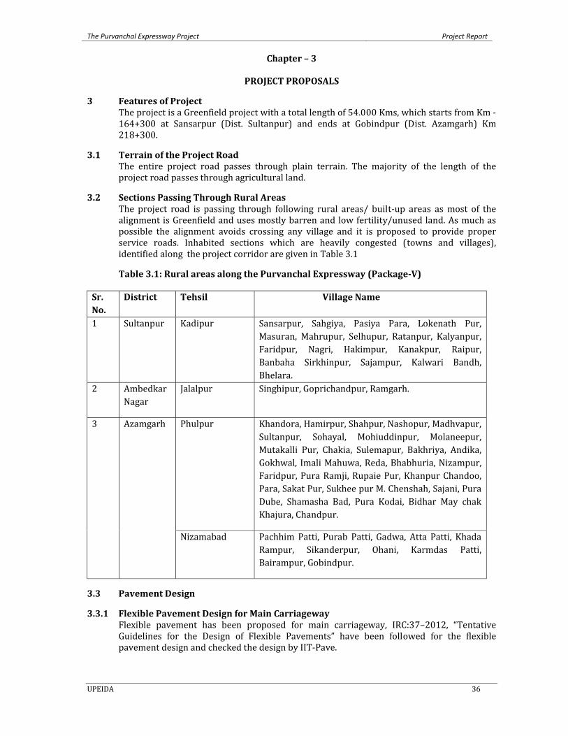
The Purvanchal Expressway Project Project Report
UPEIDA 36
Chapter – 3
PROJECT PROPOSALS
3 Features of Project The project is a Greenfield project with a total length of 54.000 Kms, which starts from Km ‐164+300 at Sansarpur (Dist. Sultanpur) and ends at Gobindpur (Dist. Azamgarh) Km 218+300.
3.1 Terrain of the Project Road The entire project road passes through plain terrain. The majority of the length of the project road passes through agricultural land.
3.2 Sections Passing Through Rural Areas The project road is passing through following rural areas/ built‐up areas as most of the alignment is Greenfield and uses mostly barren and low fertility/unused land. As much as possible the alignment avoids crossing any village and it is proposed to provide proper service roads. Inhabited sections which are heavily congested (towns and villages), identified along the project corridor are given in Table 3.1
Table 3.1: Rural areas along the Purvanchal Expressway (PackageV)
Sr. No.
District Tehsil Village Name
1 Sultanpur Kadipur Sansarpur, Sahgiya, Pasiya Para, Lokenath Pur, Masuran, Mahrupur, Selhupur, Ratanpur, Kalyanpur, Faridpur, Nagri, Hakimpur, Kanakpur, Raipur, Banbaha Sirkhinpur, Sajampur, Kalwari Bandh, Bhelara.
2 Ambedkar Nagar
Jalalpur Singhipur, Goprichandpur, Ramgarh.
3 Azamgarh Phulpur Khandora, Hamirpur, Shahpur, Nashopur, Madhvapur, Sultanpur, Sohayal, Mohiuddinpur, Molaneepur, Mutakalli Pur, Chakia, Sulemapur, Bakhriya, Andika, Gokhwal, Imali Mahuwa, Reda, Bhabhuria, Nizampur, Faridpur, Pura Ramji, Rupaie Pur, Khanpur Chandoo, Para, Sakat Pur, Sukhee pur M. Chenshah, Sajani, Pura Dube, Shamasha Bad, Pura Kodai, Bidhar May chak Khajura, Chandpur.
Nizamabad Pachhim Patti, Purab Patti, Gadwa, Atta Patti, Khada Rampur, Sikanderpur, Ohani, Karmdas Patti, Bairampur, Gobindpur.
3.3 Pavement Design
3.3.1 Flexible Pavement Design for Main Carriageway Flexible pavement has been proposed for main carriageway, IRC:37–2012, “Tentative Guidelines for the Design of Flexible Pavements” have been followed for the flexible pavement design and checked the design by IIT‐Pave.
The Purvanchal Expressway Project Project Report
UPEIDA 37
Flexible pavement has been proposed with bituminous and granular base and sub‐base for new alignment and service road consisting of various layers such as Granular Sub base (GSB), Wet Mix Macadam (WMM), Bituminous Surfacing comprising Dense Bituminous Macadam (DBM) and Bituminous Concrete (BC/SDBC up to 5 MSA).

The Purvanchal Expressway Project Project Report
UPEIDA 38
3.3.2 Material Investigations
3.3.2.1 Existing Ground Soil Testing The soil investigations along the proposed alignment for the green field project have been carried out. The soil samples have been collected and testing of the collected samples has been completed and the summary of test results is given in Table 3.2.
Table 3.2: Test Results of the Existing Soil along the Proposed Alignment
Chainage Type of soil % passing through I.S.Sieve % Sand Content
L.L. P.L. P.I. Classification as per I.S.‐1498‐1970
FreeSwelling Index (%)
Field Moisture (%)
M.D.D.(gm/cc)
O.M.C. (%)
C.B.R. (%) In soaked condition (Actual)
4.75 mm 2.00 mm 425 mic. 75 mic Symbol Typical Name
160+000
Fine Grained 98.352 95.264 91.492 73.892 24.46 27.8 25.6 2.2 ML Clayey Silt with none to low plasticity
10 6.30 1.87 13.80 6.22
165+000
Fine Grained 99.908 99.372 98.208 87.552 12.36 27.8 23.7 4.1 ML‐CL
Mixture of Silt & Clay with low to
medium plasticity
20 8.10 1.81 15.20 6.16
170+000
Fine Grained 98.31 97.81 96.74 74.42 23.89 24.8 22.1 2.7 ML Clayey Silt with none to low plasticity
10 7.30 1.86 14.3 6.05
175+000 Fine Grained 100.00 99.06 97.77 86.06 13.94 28.5 24.4 4.1 ML‐CL Mixture of Silt & Clay with low to medium plasticity
20 9.40 1.88 13.8 5.89
180+000 Fine Grained 99.94 99.38 97.59 92.07 7.87 28.7 23.5 5.2 ML‐CL Mixture of Silt & Clay with low to medium plasticity
22.22 7.80 1.85 14.50 6.05
185+000 Fine Grained 100 99.336 96.064 91.316 8.68 28.7 25.9 2.8 ML Clayey Silt with none to low plasticity
10 7.50 1.87 13.6 5.92
190+000 Fine Grained 57.00 54.96 53.51 51.39 5.61 27.7 22.1 5.6 ML‐CL Mixture of Silt & 22.22 8.30 1.97 9.60 6.05

The Purvanchal Expressway Project Project Report
UPEIDA 39
Chainage Type of soil % passing through I.S.Sieve % Sand Content
L.L. P.L. P.I. Classification as per I.S.‐1498‐1970
FreeSwelling Index (%)
Field Moisture (%)
M.D.D.(gm/cc)
O.M.C. (%)
C.B.R. (%) In soaked condition (Actual)
4.75 mm 2.00 mm 425 mic. 75 mic Symbol Typical Name
Clay with low to medium plasticity
195+000 Fine Grained 99.94 99.312 97.288 88.884 11.06 29.6 26 3.6 ML Clayey Silt with none to low plasticity
11.11 9.50 1.89 12.8 6.65
200+000 Fine Grained 99.952 99.936 99.488 87.892 12.06 28.9 23.6 5.3 ML‐CL Mixture of Silt & Clay with low to medium plasticity
22.22 5.90 1.86 13.70 6.89
205+000 Fine Grained 100 99.88 99.296 86.616 13.38 26.8 24.1 2.7 ML Clayey Silt with none to low plasticity
10 8.30 1.92 10.78 6.89
210+000 Fine Grained 100.00 99.85 98.57 87.90 12.10 28.7 25.8 2.9 ML Clayey Silt with none to low plasticity
10 6.30 1.89 11.9 6.86
215+000 Fine Grained 100.00 99.87 98.65 89.97 10.03 30.8 24.3 6.5 ML‐CL Mixture of Silt & Clay with low to medium plasticity
30 7.50 1.88 13.60 6.05
3.3.2.2 Borrow Area Soil for Subgrade Material Borrow area locations have been identified for the sub‐grade material and testing of the collected samples from trail pits have been completed.
The borrow area material test results indicates that the available CBR is in the range of 8.11% to 9.62 %. A design sub‐grade CBR (effective) of 6% has been adopted for the pavement design. The details of borrow area material and laboratory test results have been given in Table 3.3.
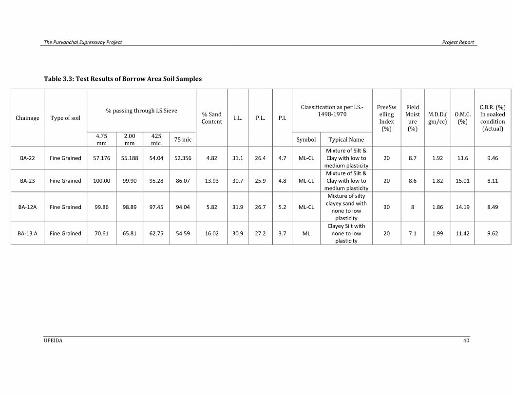
The Purvanchal Expressway Project Project Report
UPEIDA 40
Table 3.3: Test Results of Borrow Area Soil Samples
Chainage Type of soil % passing through I.S.Sieve % Sand
Content L.L. P.L. P.I.
Classification as per I.S.‐1498‐1970
FreeSwelling Index (%)
Field Moisture (%)
M.D.D.(gm/cc)
O.M.C. (%)
C.B.R. (%) In soaked condition (Actual)
4.75 mm
2.00 mm
425 mic. 75 mic Symbol Typical Name
BA‐22 Fine Grained 57.176 55.188 54.04 52.356 4.82 31.1 26.4 4.7 ML‐CL Mixture of Silt & Clay with low to medium plasticity
20 8.7 1.92 13.6 9.46
BA‐23 Fine Grained 100.00 99.90 95.28 86.07 13.93 30.7 25.9 4.8 ML‐CL Mixture of Silt & Clay with low to medium plasticity
20 8.6 1.82 15.01 8.11
BA‐12A Fine Grained 99.86 98.89 97.45 94.04 5.82 31.9 26.7 5.2 ML‐CL
Mixture of silty clayey sand with none to low plasticity
30 8 1.86 14.19 8.49
BA‐13 A Fine Grained 70.61 65.81 62.75 54.59 16.02 30.9 27.2 3.7 ML Clayey Silt with none to low plasticity
20 7.1 1.99 11.42 9.62
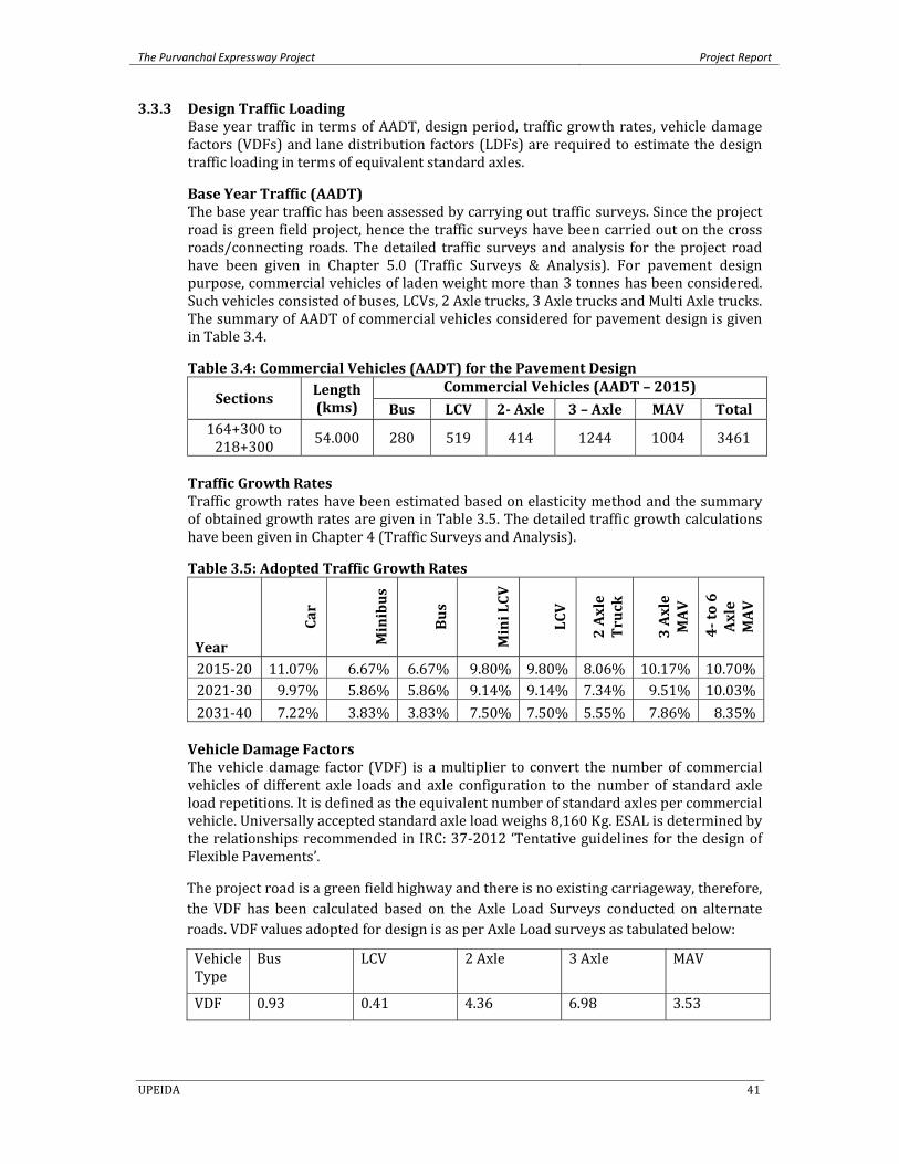
The Purvanchal Expressway Project Project Report
UPEIDA 41
3.3.3 Design Traffic Loading Base year traffic in terms of AADT, design period, traffic growth rates, vehicle damage factors (VDFs) and lane distribution factors (LDFs) are required to estimate the design traffic loading in terms of equivalent standard axles.
Base Year Traffic (AADT) The base year traffic has been assessed by carrying out traffic surveys. Since the project road is green field project, hence the traffic surveys have been carried out on the cross roads/connecting roads. The detailed traffic surveys and analysis for the project road have been given in Chapter 5.0 (Traffic Surveys & Analysis). For pavement design purpose, commercial vehicles of laden weight more than 3 tonnes has been considered. Such vehicles consisted of buses, LCVs, 2 Axle trucks, 3 Axle trucks and Multi Axle trucks. The summary of AADT of commercial vehicles considered for pavement design is given in Table 3.4.
Table 3.4: Commercial Vehicles (AADT) for the Pavement Design
Sections Length (kms)
Commercial Vehicles (AADT – 2015)
Bus LCV 2 Axle 3 – Axle MAV Total 164+300 to 218+300 54.000 280 519 414 1244 1004 3461
Traffic Growth Rates Traffic growth rates have been estimated based on elasticity method and the summary of obtained growth rates are given in Table 3.5. The detailed traffic growth calculations have been given in Chapter 4 (Traffic Surveys and Analysis).
Table 3.5: Adopted Traffic Growth Rates
Year
Car
Minibus
Bus
Mini LCV
LCV
2 Axle
Truck
3 Axle
MAV
4 to 6
Axle
MAV
2015‐20 11.07% 6.67% 6.67% 9.80% 9.80% 8.06% 10.17% 10.70%2021‐30 9.97% 5.86% 5.86% 9.14% 9.14% 7.34% 9.51% 10.03%2031‐40 7.22% 3.83% 3.83% 7.50% 7.50% 5.55% 7.86% 8.35% Vehicle Damage Factors The vehicle damage factor (VDF) is a multiplier to convert the number of commercial vehicles of different axle loads and axle configuration to the number of standard axle load repetitions. It is defined as the equivalent number of standard axles per commercial vehicle. Universally accepted standard axle load weighs 8,160 Kg. ESAL is determined by the relationships recommended in IRC: 37‐2012 ‘Tentative guidelines for the design of Flexible Pavements’.
The project road is a green field highway and there is no existing carriageway, therefore, the VDF has been calculated based on the Axle Load Surveys conducted on alternate roads. VDF values adopted for design is as per Axle Load surveys as tabulated below:
Vehicle Type
Bus LCV 2 Axle 3 Axle MAV
VDF 0.93 0.41 4.36 6.98 3.53

The Purvanchal Expressway Project Project Report
UPEIDA 42
Design Life Pavement design life is the period for which the initial design of pavement crust layers shall be carried out. Design life should not be referred as terminal stage of crust beyond which crust becomes unusable.
The flexible pavement design is to be carried out in accordance with IRC: 37‐2012, with stage construction, hence a design life of 15 years has been considered for design purpose.
Design Traffic Loading (Cumulative Million Standard Axles) For flexible pavement design traffic loading in million standard axles (MSA) has been estimated for a design life of 15 years (post construction). The design traffic is considered in terms of the cumulative number of standard axles to be carried during the design life of the road. The summary of MSA obtained and adopted is given in Table 3.6.
Table 3.6: Obtained and Adopted MSA for the Pavement Design Section Design Life 20 Years Design Life 15 Years
Km 164+300 to Km 218+300
MSA Granular MSA Bituminous 106 73
3.3.4 Flexible Pavement Design for Main Carriageway (New Construction) The IRC method for pavement design is based on limiting the vertical compressive strain on top of sub‐grade which results in permanent deformation of the pavement and the horizontal tensile strain at the bottom of the bituminous layer which results in cracking of the pavement.
The flexible pavement design has been carried out by using the procedure given in IRC: 37‐2012, thereby ensuring requisite structural layers. By considering all inputs given above the proposed flexible pavement design for the main carriageway (new construction) is given in Table 3.7.
Table 3.7: Flexible Pavement Design for Main Carriageway (New Construction)
Section
Design Life
(Years)
Design MSA
Granular
Design MSA
Bituminous
Design CBR (%)
New Crust Composition (mm)
BC DBM WMM GSB Total Thickness
164+300 to
218+300 20/15 106 73 6 50 165 105 200 520
Sub‐grade of 500 mm thickness of CBR value not less 8% and sub‐base material of CBR not less than 30% shall be used.
Paved shoulder The pavement composition of paved shoulders has been kept with the same specifications as those of the main carriageway.
3.3.5 Service Roads The Service roads are proposed to be provided at locations of the project road where it is passing through urban areas. Service roads have been designed for 5 MSA for 6% CBR. The crust composition of service roads is given in Table 3.8.
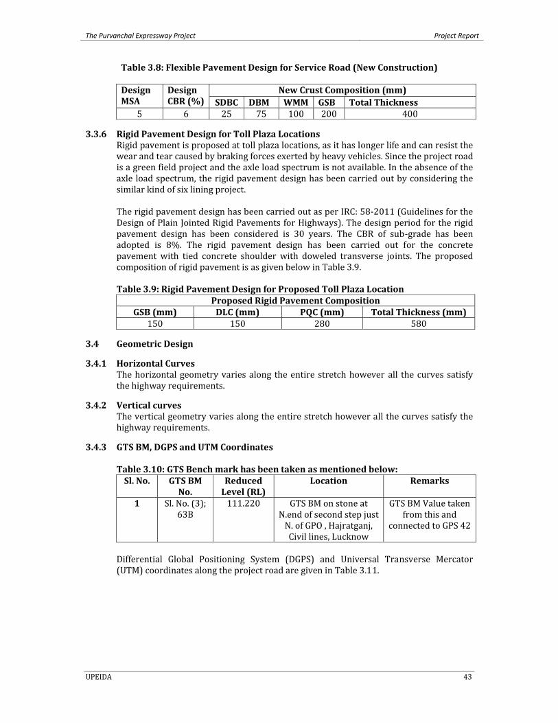
The Purvanchal Expressway Project Project Report
UPEIDA 43
Table 3.8: Flexible Pavement Design for Service Road (New Construction)
Design MSA
Design CBR (%)
New Crust Composition (mm) SDBC DBM WMM GSB Total Thickness
5 6 25 75 100 200 400
3.3.6 Rigid Pavement Design for Toll Plaza Locations Rigid pavement is proposed at toll plaza locations, as it has longer life and can resist the wear and tear caused by braking forces exerted by heavy vehicles. Since the project road is a green field project and the axle load spectrum is not available. In the absence of the axle load spectrum, the rigid pavement design has been carried out by considering the similar kind of six lining project. The rigid pavement design has been carried out as per IRC: 58‐2011 (Guidelines for the Design of Plain Jointed Rigid Pavements for Highways). The design period for the rigid pavement design has been considered is 30 years. The CBR of sub‐grade has been adopted is 8%. The rigid pavement design has been carried out for the concrete pavement with tied concrete shoulder with doweled transverse joints. The proposed composition of rigid pavement is as given below in Table 3.9.
Table 3.9: Rigid Pavement Design for Proposed Toll Plaza Location
Proposed Rigid Pavement CompositionGSB (mm) DLC (mm) PQC (mm) Total Thickness (mm)
150 150 280 580
3.4 Geometric Design
3.4.1 Horizontal Curves The horizontal geometry varies along the entire stretch however all the curves satisfy the highway requirements.
3.4.2 Vertical curves The vertical geometry varies along the entire stretch however all the curves satisfy the highway requirements.
3.4.3 GTS BM, DGPS and UTM Coordinates
Table 3.10: GTS Bench mark has been taken as mentioned below: Sl. No. GTS BM
No. Reduced Level (RL)
Location Remarks
1 Sl. No. (3); 63B
111.220 GTS BM on stone at N.end of second step just N. of GPO , Hajratganj, Civil lines, Lucknow
GTS BM Value taken from this and
connected to GPS 42
Differential Global Positioning System (DGPS) and Universal Transverse Mercator (UTM) coordinates along the project road are given in Table 3.11.
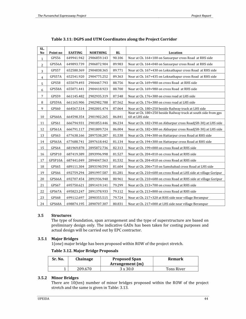
The Purvanchal Expressway Project Project Report
UPEIDA 44
Table 3.11: DGPS and UTM Coordinates along the Project Corridor
SL. No Point no EASTING NORTHING RL Location
1 GPS56 649941.942 2906859.143 90.106 Near at Ch. 164+100 on Sansarpur cross Road at RHS side
2 GPS56A 649893.739 2906872.904 89.983 Near at Ch. 164+040 on Sansarpur cross Road at RHS side
3 GPS57 652580.369 2904838.365 89.771 Near at Ch. 167+430 on Loknathapur cross Road at RHS side
4 GPS57A 652541.920 2904775.252 89.363 Near at Ch. 167+435 on Loknathapur cross Road at RHS side
5 GPS58 655079.493 2904467.793 88.756 Near at Ch. 169+980 on cross Road at RHS side
6 GPS58A 655071.441 2904418.923 88.700 Near at Ch. 169+980 on cross Road at RHS side
7 GPS59 661145.482 2902935.319 87.548 Near at Ch. 176+380 on cross road at LHS side
8 GPS59A 661165.906 2902982.788 87.562 Near at Ch. 176+380 on cross road at LHS side
9 GPS60 664567.514 2902001.474 87.064 Near at Ch. 180+250 beside Railway track at LHS side
10 GPS60A 664598.354 2901902.265 86.841 Near at Ch. 180+250 beside Railway track at south side from gps 60 at LHS side
11 GPS61 666794.931 2901853.446 86.234 Near at Ch. 182+390 on Akbarpur cross Road(SH‐30) at LHS side
12 GPS61A 666791.117 2901809.724 86.004 Near at Ch. 182+380 on Akbarpur cross Road(SH‐30) at LHS side
13 GPS63 677638.166 2897538.287 81.538 Near at Ch. 194+300 on Hattarpur cross Road at RHS side
14 GPS63A 677688.741 2897618.442 81.134 Near at Ch. 194+300 on Hattarpur cross Road at RHS side
15 GPS64 681969.878 2895872.736 82.313 Near at Ch. 199+000 on cross Road at RHS side
16 GPSP10 687419.389 2893996.998 81.527 Near at Ch. 204+810 on cross Road at RHS side
17 GPSP10A 687441.049 2894047.563 81.532 Near at Ch. 204+810 on cross Road at RHS side
18 GPS65 689111.304 2893190.593 81.604 Near at Ch. 206+710 on Samshabad cross Road at LHS side
19 GPS66 692759.294 2891997.587 81.281 Near at Ch. 210+600 on cross Road at LHS side at village Goripur
20 GPS66A 692707.454 2891936.948 80.961 Near at Ch. 210+600 on cross Road at RHS side at village Goripur
21 GPS67 695750.621 2891419.141 79.299 Near at Ch. 213+700 on cross Road at RHS side
22 GPS67A 695823.247 2891378.933 79.112 Near at Ch. 213+800 on cross Road at RHS side
23 GPS68 699112.697 2890355.515 79.724 Near at Ch. 217+320 at RHS side near village Berampur
24 GPS68A 698874.195 2890707.307 80.831 Near at Ch. 217+000 at LHS side near village Berampur
3.5 Structures The type of foundation, span arrangement and the type of superstructure are based on preliminary design only. The indicative GADs has been taken for costing purposes and actual design will be carried out by EPC contractor.
3.5.1 Major Bridges 1(one) major bridge has been proposed within ROW of the project stretch.
Table 3.12. Major Bridge Proposals
Sr. No. Chainage Proposed Span Arrangement (m)
Remark
1 209.670 3 x 30.0 Tons River
3.5.2 Minor Bridges There are 10(ten) number of minor bridges proposed within the ROW of the project stretch and the same is given in Table: 3.13.
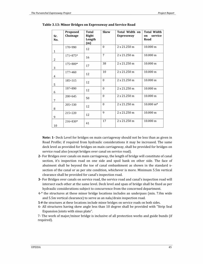
The Purvanchal Expressway Project Project Report
UPEIDA 45
Table 3.13: Minor Bridges on Expressway and Service Road
Sr. No.
Proposed Chainage
Total Right Length (m)
Skew Total Width on Expressway
Total Width on service Road
1 170+990 12
0 2 x 21.250 m 10.000 m
2 171+875* 16
7 2 x 21.250 m 10.000 m
3 175+800* 17
38 2 x 21.250 m 10.000 m
4 177+460 12
10 2 x 21.250 m 10.000 m
5 185+315 12
0 2 x 21.250 m 10.000 m
6 197+890 12 0 2 x 21.250 m 10.000 m
7 200+645 50
0 2 x 21.250 m 10.000 m
8 205+330 12
0 2 x 21.250 m 10.000 m#
9 215+220 12
9 2 x 21.250 m 10.000 m
10 216+830* 41
17 2 x 21.250 m 10.000 m
Note: 1 Deck Level for bridges on main carriageway should not be less than as given in Road Profile; if required from hydraulic considerations it may be increased. The same deck level as provided for bridges on main carriageway, shall be provided for bridges on service road also (except bridges over canal on service road).
2 For Bridges over canals on main carriageway, the length of bridge will constitute of canal section, it’s inspection road on one side and spoil bank on other side. The face of abutment shall be beyond the toe of canal embankment as shown in the standard x‐section of the canal or as per site condition, whichever is more. Minimum 5.5m vertical clearance shall be provided for canal’s inspection road.
3 For Bridges over canals on service road, the service road and canal’s inspection road will intersect each other at the same level. Deck level and span of bridge shall be fixed as per hydraulic considerations subject to concurrence from the concerned department.
4‐* the structures at these minor bridge locations includes an underpass (min. 7.0m wide and 5.5m vertical clearance) to serve as an nala/drain inspection road.
5-# the structures at these locations include minor bridges on service roads on both sides. 6‐ All structures having skew angle less than 10 degree shall be provided with ”Strip Seal Expansion Joints with sinus plate”.
7‐ The work of major/minor bridge is inclusive of all protection works and guide bunds (if required).

The Purvanchal Expressway Project Project Report
UPEIDA 46
3.5.3 Vehicular Underpass
3 (three) numbers of vehicular underpasses and 20 (twenty) numbers of light vehicular underpasses have been proposed within the ROW of the project Stretch and the same are given in Table 3.14.
Table 3.14: Proposed Vehicular Underpasses & Light Vehicular Underpasses
within ROW of the Project Stretch
Proposed Vehicular Underpass (VUP)
Sr. No.
Chainage Proposed Span Arrangement Remark
1 188+815 1 x 12.0 x 5.5 Pawai – Mittupur Road 2 203+415 2 x 12.0 x 5.5 MDR 97 E 3 210+510 1 x 12.0 x 5.5 Phulpur – Durvasa Road
Proposed Light Vehicular Underpass (LVU)
Sr. No. Chainage Proposed Span Arrangement
Remark
1 165+185 1 x 10.5 x 4.3 BT Road ( Sahigia)2 167+820 1 x 10.5 x 4.3 BT Road ( Masuran)3 169+880 1 x 10.5 x 4.3 BT Road ( Salhoopara)4 175+150 1 x 10.5 x 4.3 BT Road ( Hakimpur)5 176+280 1 x 10.5 x 4.3 BT Road (Kanakpur)6 179+595 1 x 10.5 x 4.3 BT Road (Sajampur)7 180+610 1 x 10.5 x 3.5 BT Road8 184+325 1 x 10.5 x 4.3 Cart Track (Hamirpur)9 187+495 1 x 10.5 x 4.3 Shahpur – Nashopur Road 10 190+260 1 x 10.5 x 4.3 Bazar Murar – Gaddopur Road 11 191+860 1 x 10.5 x 4.3 Sulemapur Road12 194+200 1 x 10.5 x 4.3 Andika – Chhajjo Patti Road 13 196+540 1 x 10.5 x 4.3 Fatampur Road14 205+110 1 x 10.5 x 4.3 Khorason Road15 206+610 1 x 10.5 x 4.3 Chouphala – Khorason Road 16 208+470 1 x 10.5 x 4.3 Chak Amanshah road17 211+995 1 x 10.5 x 4.3 Ubhiri Purab Patti Road18 213+495 1 x 10.5 x 4.3 Garhwa Road19 216+460 1 x 10.5 x 4.3 BT Road20 218+140 1 x 10.5 x 4.3 Bairampur Village (BT Road)
3.5.4 Pedestrian Underpass 8 (eight) PUPs have been proposed within the ROW of the project stretch to meet the requirement as given in Guidelines for Expressways. The consultant ensured that the location of proposed PUPs suits the agrarian traffic requirements. The list of proposed PUPs within the ROW of the project stretch is given in Table: 3.15.
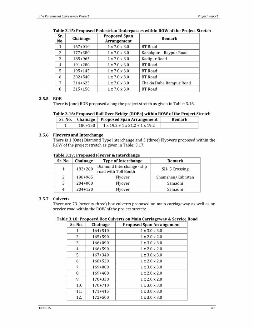
The Purvanchal Expressway Project Project Report
UPEIDA 47
Table 3.15: Proposed Pedestrian Underpasses within ROW of the Project Stretch Sr. No.
Chainage Proposed Span Arrangement
Remark
1 167+010 1 x 7.0 x 3.0 BT Road 2 177+380 1 x 7.0 x 3.0 Kanakpur – Raypur Road 3 185+965 1 x 7.0 x 3.0 Kadipur Road 4 191+280 1 x 7.0 x 3.0 BT Road 5 195+145 1 x 7.0 x 3.0 BT Road 6 202+540 1 x 7.0 x 3.0 BT Road 7 214+625 1 x 7.0 x 3.0 Chakia Dube Rampur Road 8 215+150 1 x 7.0 x 3.0 BT Road
3.5.5 ROB There is (one) ROB proposed along the project stretch as given in Table: 3.16.
Table 3.16: Proposed Rail Over Bridge (ROBs) within ROW of the Project Stretch
Sr. No. Chainage Proposed Span Arrangement Remark 1 180+150 1 x 19.2 + 1 x 31.2 + 1 x 19.2
3.5.6 Flyovers and Interchange There is 1 (One) Diamond Type Interchange and 3 (three) Flyovers proposed within the ROW of the project stretch as given in Table: 3.17.
Table 3.17: Proposed Flyover & Interchange Sr. No. Chainage Type of Interchange Remark
1 182+280 Diamond Interchange ‐ slip road with Toll Booth SH‐ 5 Crossing
2 198+965 Flyover Shamshan/Kabrstan 3 204+000 Flyover Samadhi 4 204+120 Flyover Samadhi
3.5.7 Culverts There are 73 (seventy three) box culverts proposed on main carriageway as well as on service road within the ROW of the project stretch:
Table 3.18: Proposed Box Culverts on Main Carriageway & Service Road
Sr. No. Chainage Proposed Span Arrangement 1. 164+510 1 x 3.0 x 3.0 2. 165+590 1 x 2.0 x 2.0 3. 166+090 1 x 3.0 x 3.0 4. 166+590 1 x 2.0 x 2.0 5. 167+340 1 x 3.0 x 3.0 6. 168+520 1 x 2.0 x 2.0 7. 169+000 1 x 3.0 x 3.0 8. 169+480 1 x 2.0 x 2.0 9. 170+330 1 x 2.0 x 2.0 10. 170+710 1 x 3.0 x 3.0 11. 171+415 1 x 3.0 x 3.0 12. 172+500 1 x 3.0 x 3.0
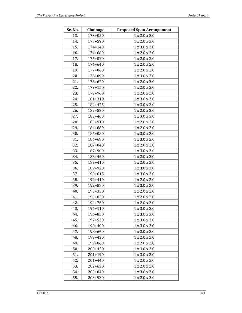
The Purvanchal Expressway Project Project Report
UPEIDA 48
Sr. No. Chainage Proposed Span Arrangement 13. 173+050 1 x 2.0 x 2.0 14. 173+590 1 x 2.0 x 2.0 15. 174+140 1 x 3.0 x 3.0 16. 174+680 1 x 2.0 x 2.0 17. 175+520 1 x 2.0 x 2.0 18. 176+640 1 x 2.0 x 2.0 19. 177+060 1 x 2.0 x 2.0 20. 178+090 1 x 3.0 x 3.0 21. 178+620 1 x 2.0 x 2.0 22. 179+150 1 x 2.0 x 2.0 23. 179+960 1 x 2.0 x 2.0 24. 181+310 1 x 3.0 x 3.0 25. 182+475 1 x 3.0 x 3.0 26. 182+880 1 x 2.0 x 2.0 27. 183+400 1 x 3.0 x 3.0 28. 183+910 1 x 2.0 x 2.0 29. 184+680 1 x 2.0 x 2.0 30. 185+080 1 x 3.0 x 3.0 31. 186+680 1 x 3.0 x 3.0 32. 187+040 1 x 2.0 x 2.0 33. 187+900 1 x 3.0 x 3.0 34. 188+460 1 x 2.0 x 2.0 35. 189+410 1 x 2.0 x 2.0 36. 189+920 1 x 3.0 x 3.0 37. 190+615 1 x 3.0 x 3.0 38. 192+410 1 x 2.0 x 2.0 39. 192+880 1 x 3.0 x 3.0 40. 193+350 1 x 2.0 x 2.0 41. 193+820 1 x 2.0 x 2.0 42. 194+760 1 x 2.0 x 2.0 43. 196+110 1 x 3.0 x 3.0 44. 196+830 1 x 3.0 x 3.0 45. 197+520 1 x 3.0 x 3.0 46. 198+400 1 x 3.0 x 3.0 47. 198+660 1 x 2.0 x 2.0 48. 199+420 1 x 2.0 x 2.0 49. 199+860 1 x 2.0 x 2.0 50. 200+420 1 x 3.0 x 3.0 51. 201+190 1 x 3.0 x 3.0 52. 201+440 1 x 2.0 x 2.0 53. 202+650 1 x 2.0 x 2.0 54. 203+040 1 x 3.0 x 3.0 55. 203+930 1 x 2.0 x 2.0
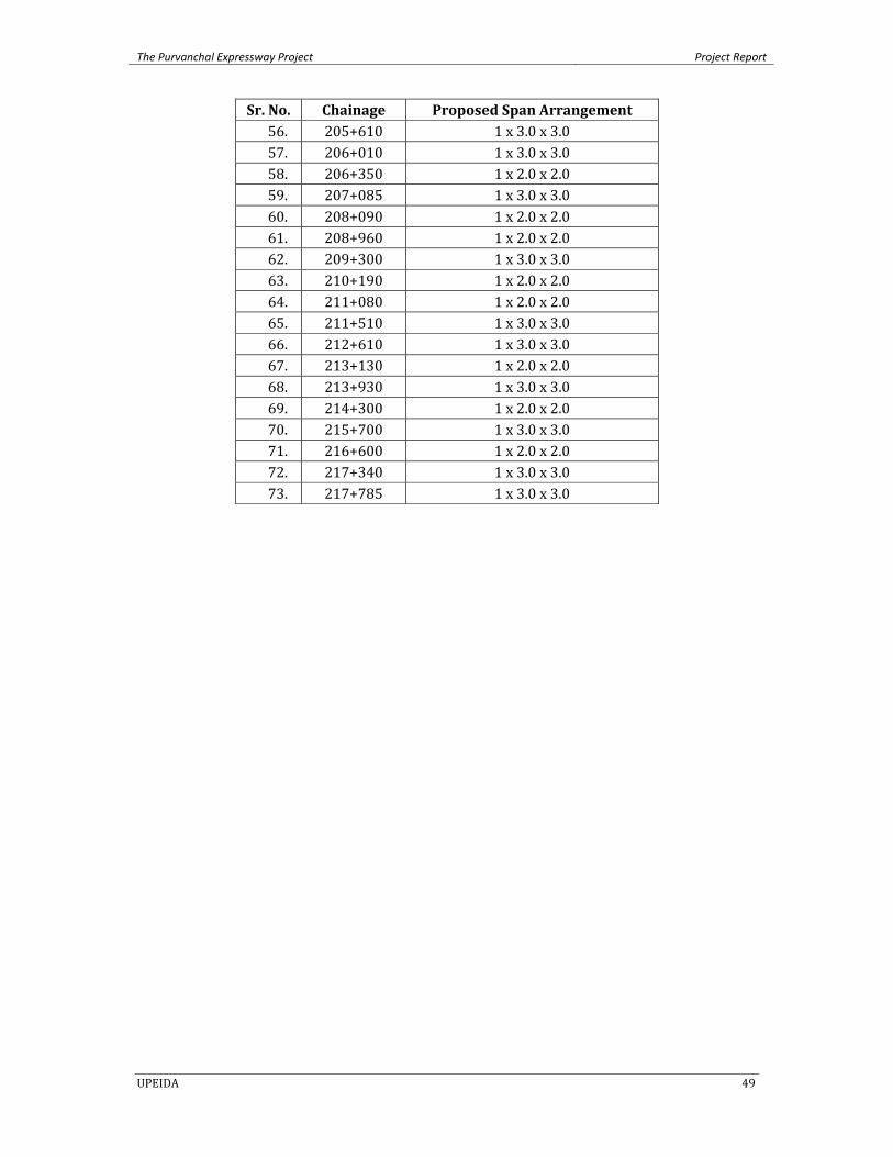
The Purvanchal Expressway Project Project Report
UPEIDA 49
Sr. No. Chainage Proposed Span Arrangement 56. 205+610 1 x 3.0 x 3.0 57. 206+010 1 x 3.0 x 3.0 58. 206+350 1 x 2.0 x 2.0 59. 207+085 1 x 3.0 x 3.0 60. 208+090 1 x 2.0 x 2.0 61. 208+960 1 x 2.0 x 2.0 62. 209+300 1 x 3.0 x 3.0 63. 210+190 1 x 2.0 x 2.0 64. 211+080 1 x 2.0 x 2.0 65. 211+510 1 x 3.0 x 3.0 66. 212+610 1 x 3.0 x 3.0 67. 213+130 1 x 2.0 x 2.0 68. 213+930 1 x 3.0 x 3.0 69. 214+300 1 x 2.0 x 2.0 70. 215+700 1 x 3.0 x 3.0 71. 216+600 1 x 2.0 x 2.0 72. 217+340 1 x 3.0 x 3.0 73. 217+785 1 x 3.0 x 3.0

The Purvanchal Expressway Project Project Report
UPEIDA 50
Chapter – 4
TRAFFIC, TOLL AND FINANCIAL STUDIES
4 Traffic, Toll and Financial Studies is given in a separate report.
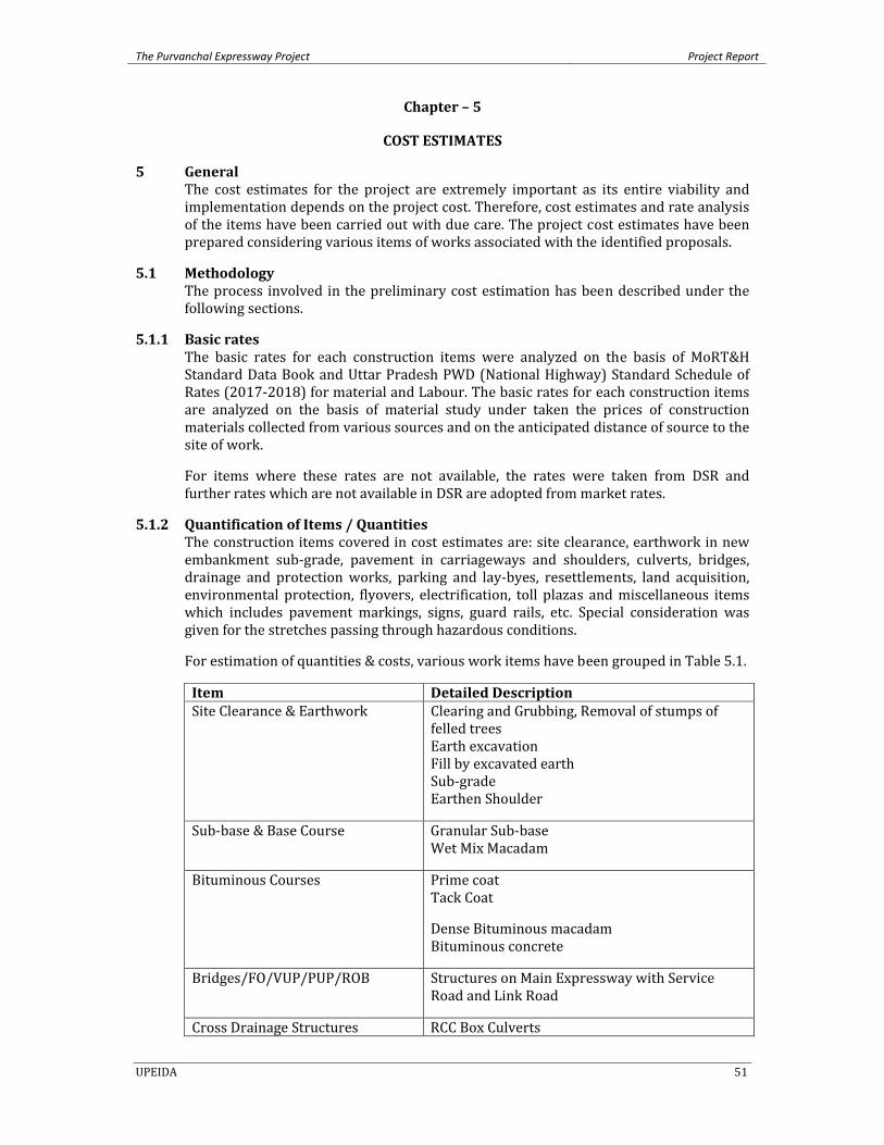
The Purvanchal Expressway Project Project Report
UPEIDA 51
Chapter – 5
COST ESTIMATES
5 General The cost estimates for the project are extremely important as its entire viability and implementation depends on the project cost. Therefore, cost estimates and rate analysis of the items have been carried out with due care. The project cost estimates have been prepared considering various items of works associated with the identified proposals.
5.1 Methodology The process involved in the preliminary cost estimation has been described under the following sections.
5.1.1 Basic rates The basic rates for each construction items were analyzed on the basis of MoRT&H Standard Data Book and Uttar Pradesh PWD (National Highway) Standard Schedule of Rates (2017‐2018) for material and Labour. The basic rates for each construction items are analyzed on the basis of material study under taken the prices of construction materials collected from various sources and on the anticipated distance of source to the site of work.
For items where these rates are not available, the rates were taken from DSR and further rates which are not available in DSR are adopted from market rates.
5.1.2 Quantification of Items / Quantities The construction items covered in cost estimates are: site clearance, earthwork in new embankment sub‐grade, pavement in carriageways and shoulders, culverts, bridges, drainage and protection works, parking and lay‐byes, resettlements, land acquisition, environmental protection, flyovers, electrification, toll plazas and miscellaneous items which includes pavement markings, signs, guard rails, etc. Special consideration was given for the stretches passing through hazardous conditions.
For estimation of quantities & costs, various work items have been grouped in Table 5.1.
Item Detailed DescriptionSite Clearance & Earthwork
Clearing and Grubbing, Removal of stumps of felled trees Earth excavation Fill by excavated earth Sub‐grade Earthen Shoulder
Sub‐base & Base Course Granular Sub‐base Wet Mix Macadam
Bituminous Courses Prime coat Tack Coat
Dense Bituminous macadam Bituminous concrete
Bridges/FO/VUP/PUP/ROB
Structures on Main Expressway with Service Road and Link Road
Cross Drainage Structures RCC Box Culverts
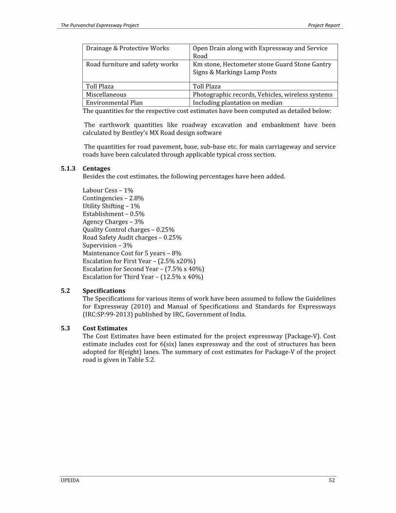
The Purvanchal Expressway Project Project Report
UPEIDA 52
Drainage & Protective Works Open Drain along with Expressway and Service Road
Road furniture and safety works
Km stone, Hectometer stone Guard Stone Gantry Signs & Markings Lamp Posts
Toll Plaza Toll Plaza Miscellaneous Photographic records, Vehicles, wireless systems Environmental Plan Including plantation on median The quantities for the respective cost estimates have been computed as detailed below:
The earthwork quantities like roadway excavation and embankment have been calculated by Bentley’s MX Road design software
The quantities for road pavement, base, sub‐base etc. for main carriageway and service roads have been calculated through applicable typical cross section.
5.1.3 Centages Besides the cost estimates, the following percentages have been added.
Labour Cess – 1% Contingencies – 2.8% Utility Shifting – 1% Establishment – 0.5% Agency Charges – 3% Quality Control charges – 0.25% Road Safety Audit charges – 0.25% Supervision – 3% Maintenance Cost for 5 years – 8% Escalation for First Year – (2.5% x20%) Escalation for Second Year – (7.5% x 40%) Escalation for Third Year – (12.5% x 40%)
5.2 Specifications The Specifications for various items of work have been assumed to follow the Guidelines for Expressway (2010) and Manual of Specifications and Standards for Expressways (IRC:SP:99‐2013) published by IRC, Government of India.
5.3 Cost Estimates The Cost Estimates have been estimated for the project expressway (Package‐V). Cost estimate includes cost for 6(six) lanes expressway and the cost of structures has been adopted for 8(eight) lanes. The summary of cost estimates for Package‐V of the project road is given in Table 5.2.
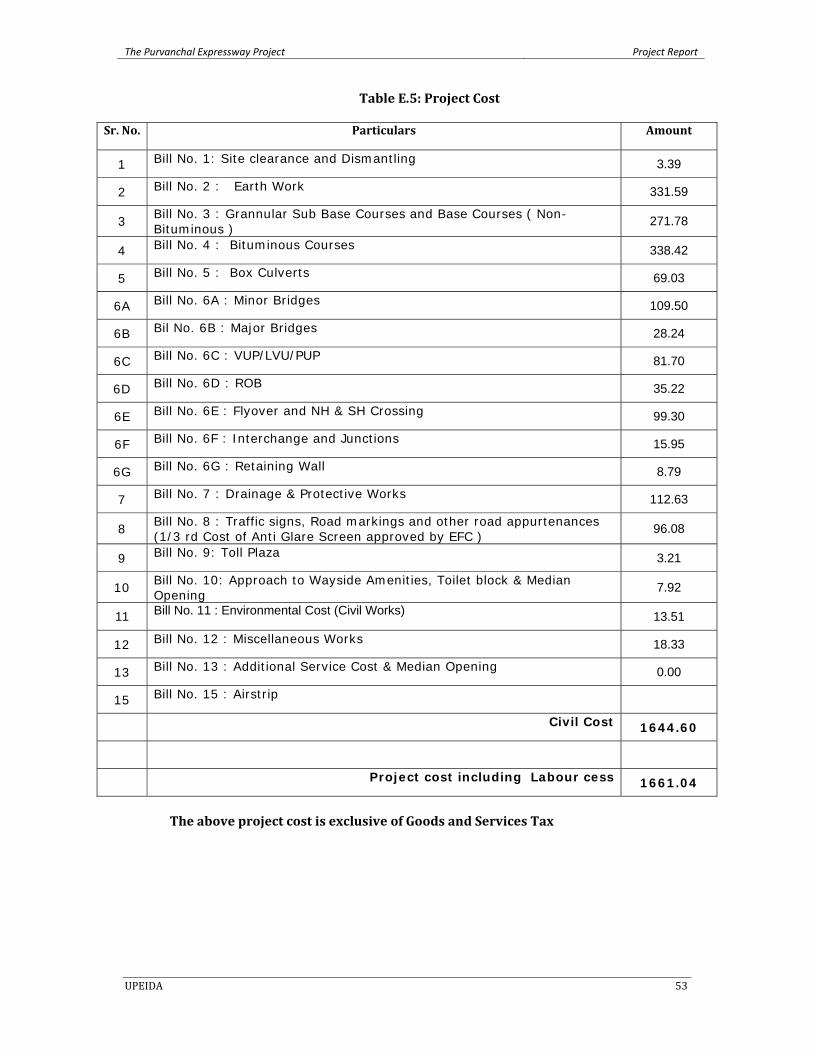
The Purvanchal Expressway Project Project Report
UPEIDA 53
Table E.5: Project Cost
Sr. No. Particulars Amount
1 Bill No. 1: Site clearance and Dismantling 3.39
2 Bill No. 2 : Earth Work 331.59
3 Bill No. 3 : Grannular Sub Base Courses and Base Courses ( Non- Bituminous )
271.78
4 Bill No. 4 : Bituminous Courses 338.42
5 Bill No. 5 : Box Culverts 69.03
6A Bill No. 6A : Minor Bridges 109.50
6B Bil No. 6B : Major Bridges 28.24
6C Bill No. 6C : VUP/LVU/PUP 81.70
6D Bill No. 6D : ROB 35.22
6E Bill No. 6E : Flyover and NH & SH Crossing 99.30
6F Bill No. 6F : Interchange and Junctions 15.95
6G Bill No. 6G : Retaining Wall 8.79
7 Bill No. 7 : Drainage & Protective Works 112.63
8 Bill No. 8 : Traffic signs, Road markings and other road appurtenances (1/3 rd Cost of Anti Glare Screen approved by EFC )
96.08
9 Bill No. 9: Toll Plaza 3.21
10 Bill No. 10: Approach to Wayside Amenities, Toilet block & Median Opening
7.92
11 Bill No. 11 : Environmental Cost (Civil Works) 13.51
12 Bill No. 12 : Miscellaneous Works 18.33
13 Bill No. 13 : Additional Service Cost & Median Opening 0.00
15 Bill No. 15 : Airstrip
Civil Cost 1644.60
Project cost including Labour cess 1661.04
The above project cost is exclusive of Goods and Services Tax
The Purvanchal Expressway Project Project Report
UPEIDA 54
Chapter – 6
ECONOMIC STUDIES
6 Economic Studies is given in a separate report
The Purvanchal Expressway Project Project Report
UPEIDA 55
Chapter 7
ENVIRONMENTAL SCREENING AND PRELIMINARY ASSESSMENT
7.1 Background
The Uttar Pradesh Expressway Industrial Development Authority (Government of UP) has been entrusted to develop the access controlled Purvanchal Expressway, which traverses entire state to integrate creation of World Class infrastructure with industrial and economic development, IIDC Limited has been engaged by UPEIDA to provide technical support in the project preparation of the proposed Purvanchal Expressway. Agra Lucknow section of this expressway is already under construction. This expressway from Chand sarai in District Lucknow to Haidariya in District Ghazipur (about 340.956 Kms) is being proposed to develop on EPC mode. The proposed expressway will also have economic and industrial corridors along the link expressway which will be connected to the proposed expressway. This proposed Expressway project shall create immense employment opportunities to the local people of eastern region of the State because of induced economic and industrial development. The proposed expressway has been divided in 8 packages and the chainages of Package ‐ I is as presented in Table below.
Table 7.1: Chainagewise details of Package V
The present environmental screening has been carried out for Package–V which is from Sansarpur in Dist. Sultanpur (Km 164+300) to Gobindpur in Dist. Azamgarh (218+300). Environmental screening study has been carried out to identify critical issues and areas that would be studied in detail for impact assessment, mitigation measures and management plan. Further details will be taken up during subsequent stages of the project preparation. This report has been prepared based mainly on field survey and collection of secondary data.
In the screening stage, existing environmental set‐up of the study corridor in general i.e., the Corridor of Impact (CoI) and the existing Right of Way (RoW) in particular were studied and is described in subsequent sections. The entire EIA study was carried out within existing policy, legal and administrative framework considering the applicable environmental legislation, regulations and guidelines.
The Right of Way (RoW) of the proposed expressway is 120 meter. The proposed expressway will have 6‐Lane access controlled expressway and service roads on one side of expressway. The connectivity to the proposed expressway will be through grade‐separator such as clover leaf, underpasses and overpasses at pre‐defined locations. Flexible pavements are proposed for main carriage way and service roads throughout the expressway except at toll plaza where rigid pavements are being proposed. All geometric design has been carried out as per the IRC and MoRT&H standards and specifications. The design speed has been kept quite uniform, and design speed even at curves is 120 kmph.
7.2 Description of the Project Area
The project districts are located in middle Gangetic Plains. The entire project area is is alluvial plain formed by Ganga and its tributaries. The climate of project area is predominantly subtropical & is characterized by hot summer and cool winter. Most of
Package From To Chainage Length (Kms)
I Sansarpur (Sultanpur)
Gobindpur(Azamgarh) 164+300 to 218+300 54.000
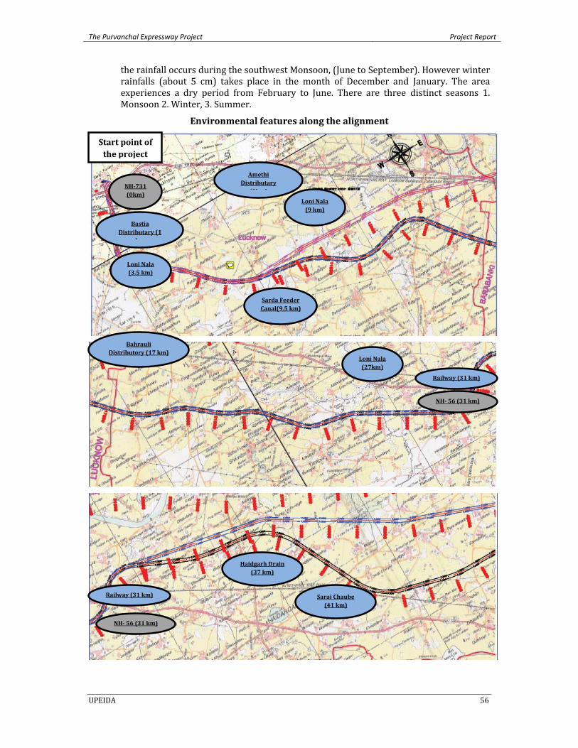
The Purvanchal Expressway Project Project Report
UPEIDA 56
the rainfall occurs during the southwest Monsoon, (June to September). However winter rainfalls (about 5 cm) takes place in the month of December and January. The area experiences a dry period from February to June. There are three distinct seasons 1. Monsoon 2. Winter, 3. Summer.
Environmental features along the alignment
NH731 (0km)
Start point of the project
Bastia Distributary (1
km
Amethi Distributary
(9k )
Sarda Feeder Canal(9.5 km)
Loni Nala (9 km)
Bahrauli Distributory (17 km)
NH 56 (31 km)
Railway (31 km)
Railway (31 km)
Loni Nala (27km)
NH 56 (31 km)
Sarai Chaube (41 km)
Haidgarh Drain (37 km)
Loni Nala (3.5 km)
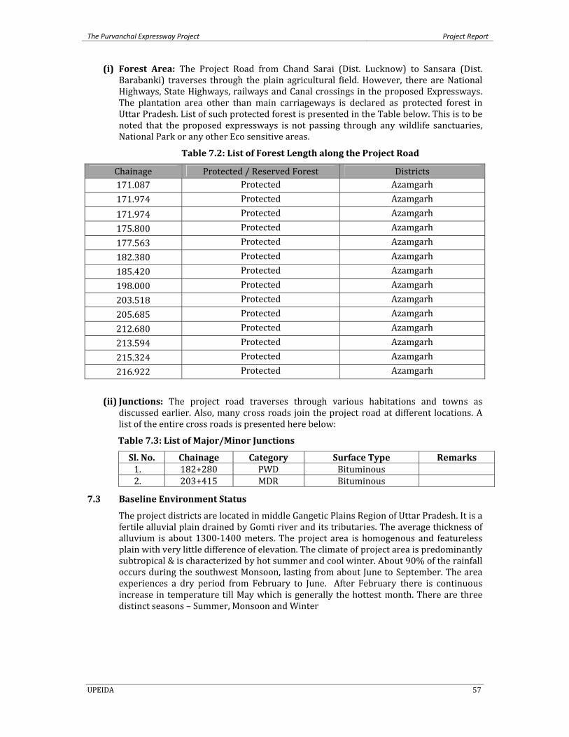
The Purvanchal Expressway Project Project Report
UPEIDA 57
(i) Forest Area: The Project Road from Chand Sarai (Dist. Lucknow) to Sansara (Dist. Barabanki) traverses through the plain agricultural field. However, there are National Highways, State Highways, railways and Canal crossings in the proposed Expressways. The plantation area other than main carriageways is declared as protected forest in Uttar Pradesh. List of such protected forest is presented in the Table below. This is to be noted that the proposed expressways is not passing through any wildlife sanctuaries, National Park or any other Eco sensitive areas.
Table 7.2: List of Forest Length along the Project Road
Chainage Protected / Reserved Forest Districts 171.087 Protected Azamgarh 171.974 Protected Azamgarh 171.974 Protected Azamgarh 175.800 Protected Azamgarh 177.563 Protected Azamgarh 182.380 Protected Azamgarh 185.420 Protected Azamgarh 198.000 Protected Azamgarh 203.518 Protected Azamgarh 205.685 Protected Azamgarh 212.680 Protected Azamgarh 213.594 Protected Azamgarh 215.324 Protected Azamgarh 216.922 Protected Azamgarh
(ii) Junctions: The project road traverses through various habitations and towns as discussed earlier. Also, many cross roads join the project road at different locations. A list of the entire cross roads is presented here below:
Table 7.3: List of Major/Minor Junctions
Sl. No. Chainage Category Surface Type Remarks 1. 182+280 PWD Bituminous 2. 203+415 MDR Bituminous
7.3 Baseline Environment Status
The project districts are located in middle Gangetic Plains Region of Uttar Pradesh. It is a fertile alluvial plain drained by Gomti river and its tributaries. The average thickness of alluvium is about 1300‐1400 meters. The project area is homogenous and featureless plain with very little difference of elevation. The climate of project area is predominantly subtropical & is characterized by hot summer and cool winter. About 90% of the rainfall occurs during the southwest Monsoon, lasting from about June to September. The area experiences a dry period from February to June. After February there is continuous increase in temperature till May which is generally the hottest month. There are three distinct seasons – Summer, Monsoon and Winter
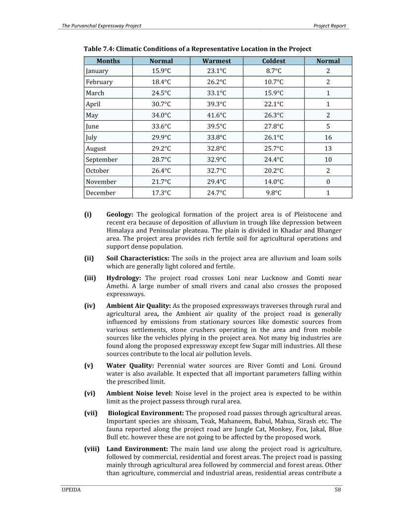
The Purvanchal Expressway Project Project Report
UPEIDA 58
Table 7.4: Climatic Conditions of a Representative Location in the Project
Months Normal Warmest Coldest Normal January 15.9°C 23.1°C 8.7°C 2February 18.4°C 26.2°C 10.7°C 2March 24.5°C 33.1°C 15.9°C 1April 30.7°C 39.3°C 22.1°C 1May 34.0°C 41.6°C 26.3°C 2June 33.6°C 39.5°C 27.8°C 5July 29.9°C 33.8°C 26.1°C 16August 29.2°C 32.8°C 25.7°C 13September 28.7°C 32.9°C 24.4°C 10October 26.4°C 32.7°C 20.2°C 2November 21.7°C 29.4°C 14.0°C 0December 17.3°C 24.7°C 9.8°C 1
(i) Geology: The geological formation of the project area is of Pleistocene and recent era because of deposition of alluvium in trough like depression between Himalaya and Peninsular pleateau. The plain is divided in Khadar and Bhanger area. The project area provides rich fertile soil for agricultural operations and support dense population.
(ii) Soil Characteristics: The soils in the project area are alluvium and loam soils which are generally light colored and fertile.
(iii) Hydrology: The project road crosses Loni near Lucknow and Gomti near Amethi. A large number of small rivers and canal also crosses the proposed expressways.
(iv) Ambient Air Quality: As the proposed expressways traverses through rural and agricultural area, the Ambient air quality of the project road is generally influenced by emissions from stationary sources like domestic sources from various settlements, stone crushers operating in the area and from mobile sources like the vehicles plying in the project area. Not many big industries are found along the proposed expressway except few Sugar mill industries. All these sources contribute to the local air pollution levels.
(v) Water Quality: Perennial water sources are River Gomti and Loni. Ground water is also available. It expected that all important parameters falling within the prescribed limit.
(vi) Ambient Noise level: Noise level in the project area is expected to be within limit as the project passess through rural area.
(vii) Biological Environment: The proposed road passes through agricultural areas. Important species are shissam, Teak, Mahaneem, Babul, Mahua, Sirash etc. The fauna reported along the project road are Jungle Cat, Monkey, Fox, Jakal, Blue Bull etc. however these are not going to be affected by the proposed work.
(viii) Land Environment: The main land use along the project road is agriculture, followed by commercial, residential and forest areas. The project road is passing mainly through agricultural area followed by commercial and forest areas. Other than agriculture, commercial and industrial areas, residential areas contribute a
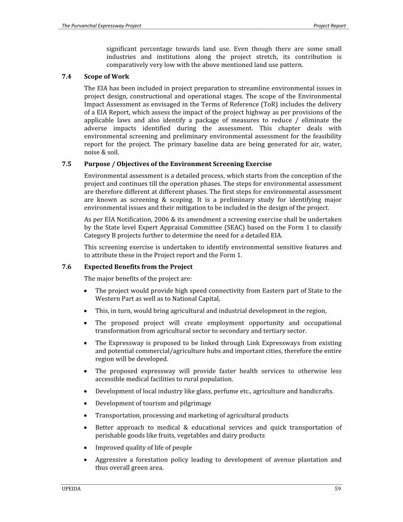
The Purvanchal Expressway Project Project Report
UPEIDA 59
significant percentage towards land use. Even though there are some small industries and institutions along the project stretch, its contribution is comparatively very low with the above mentioned land use pattern.
7.4 Scope of Work
The EIA has been included in project preparation to streamline environmental issues in project design, constructional and operational stages. The scope of the Environmental Impact Assessment as envisaged in the Terms of Reference (ToR) includes the delivery of a EIA Report, which assess the impact of the project highway as per provisions of the applicable laws and also identify a package of measures to reduce / eliminate the adverse impacts identified during the assessment. This chapter deals with environmental screening and preliminary environmental assessment for the feasibility report for the project. The primary baseline data are being generated for air, water, noise & soil.
7.5 Purpose / Objectives of the Environment Screening Exercise
Environmental assessment is a detailed process, which starts from the conception of the project and continues till the operation phases. The steps for environmental assessment are therefore different at different phases. The first steps for environmental assessment are known as screening & scoping. It is a preliminary study for identifying major environmental issues and their mitigation to be included in the design of the project.
As per EIA Notification, 2006 & its amendment a screening exercise shall be undertaken by the State level Expert Appraisal Committee (SEAC) based on the Form 1 to classify Category B projects further to determine the need for a detailed EIA.
This screening exercise is undertaken to identify environmental sensitive features and to attribute these in the Project report and the Form 1.
7.6 Expected Benefits from the Project
The major benefits of the project are:
• The project would provide high speed connectivity from Eastern part of State to the Western Part as well as to National Capital,
• This, in turn, would bring agricultural and industrial development in the region,
• The proposed project will create employment opportunity and occupational transformation from agricultural sector to secondary and tertiary sector.
• The Expressway is proposed to be linked through Link Expressways from existing and potential commercial/agriculture hubs and important cities, therefore the entire region will be developed.
• The proposed expressway will provide faster health services to otherwise less accessible medical facilities to rural population.
• Development of local industry like glass, perfume etc., agriculture and handicrafts.
• Development of tourism and pilgrimage
• Transportation, processing and marketing of agricultural products
• Better approach to medical & educational services and quick transportation of perishable goods like fruits, vegetables and dairy products
• Improved quality of life of people
• Aggressive a forestation policy leading to development of avenue plantation and thus overall green area.
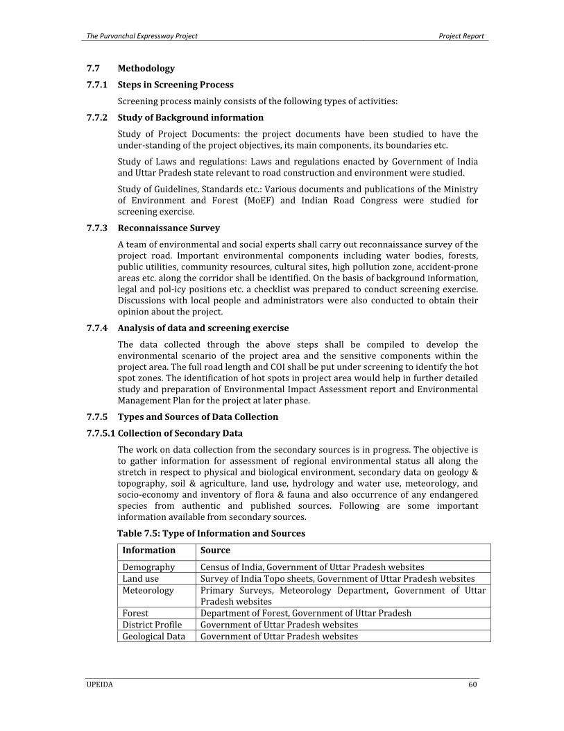
The Purvanchal Expressway Project Project Report
UPEIDA 60
7.7 Methodology
7.7.1 Steps in Screening Process
Screening process mainly consists of the following types of activities:
7.7.2 Study of Background information
Study of Project Documents: the project documents have been studied to have the under‐standing of the project objectives, its main components, its boundaries etc.
Study of Laws and regulations: Laws and regulations enacted by Government of India and Uttar Pradesh state relevant to road construction and environment were studied.
Study of Guidelines, Standards etc.: Various documents and publications of the Ministry of Environment and Forest (MoEF) and Indian Road Congress were studied for screening exercise.
7.7.3 Reconnaissance Survey
A team of environmental and social experts shall carry out reconnaissance survey of the project road. Important environmental components including water bodies, forests, public utilities, community resources, cultural sites, high pollution zone, accident‐prone areas etc. along the corridor shall be identified. On the basis of background information, legal and pol‐icy positions etc. a checklist was prepared to conduct screening exercise. Discussions with local people and administrators were also conducted to obtain their opinion about the project.
7.7.4 Analysis of data and screening exercise
The data collected through the above steps shall be compiled to develop the environmental scenario of the project area and the sensitive components within the project area. The full road length and COI shall be put under screening to identify the hot spot zones. The identification of hot spots in project area would help in further detailed study and preparation of Environmental Impact Assessment report and Environmental Management Plan for the project at later phase.
7.7.5 Types and Sources of Data Collection
7.7.5.1 Collection of Secondary Data The work on data collection from the secondary sources is in progress. The objective is to gather information for assessment of regional environmental status all along the stretch in respect to physical and biological environment, secondary data on geology & topography, soil & agriculture, land use, hydrology and water use, meteorology, and socio‐economy and inventory of flora & fauna and also occurrence of any endangered species from authentic and published sources. Following are some important information available from secondary sources.
Table 7.5: Type of Information and Sources
Information Source
Demography Census of India, Government of Uttar Pradesh websites Land use Survey of India Topo sheets, Government of Uttar Pradesh websites Meteorology Primary Surveys, Meteorology Department, Government of Uttar
Pradesh websites Forest Department of Forest, Government of Uttar Pradesh District Profile Government of Uttar Pradesh websites Geological Data Government of Uttar Pradesh websites
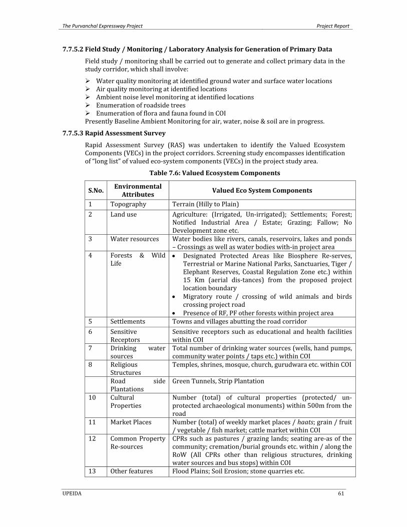
The Purvanchal Expressway Project Project Report
UPEIDA 61
7.7.5.2 Field Study / Monitoring / Laboratory Analysis for Generation of Primary Data Field study / monitoring shall be carried out to generate and collect primary data in the study corridor, which shall involve:
Water quality monitoring at identified ground water and surface water locations Air quality monitoring at identified locations Ambient noise level monitoring at identified locations Enumeration of roadside trees Enumeration of flora and fauna found in COI
Presently Baseline Ambient Monitoring for air, water, noise & soil are in progress.
7.7.5.3 Rapid Assessment Survey Rapid Assessment Survey (RAS) was undertaken to identify the Valued Ecosystem Components (VECs) in the project corridors. Screening study encompasses identification of “long list” of valued eco‐system components (VECs) in the project study area.
Table 7.6: Valued Ecosystem Components
S.No. Environmental Attributes
Valued Eco System Components
1 Topography Terrain (Hilly to Plain) 2 Land use Agriculture: (Irrigated, Un‐irrigated); Settlements; Forest;
Notified Industrial Area / Estate; Grazing; Fallow; No Development zone etc.
3 Water resources Water bodies like rivers, canals, reservoirs, lakes and ponds – Crossings as well as water bodies with‐in project area
4 Forests & Wild Life
• Designated Protected Areas like Biosphere Re‐serves, Terrestrial or Marine National Parks, Sanctuaries, Tiger / Elephant Reserves, Coastal Regulation Zone etc.) within 15 Km (aerial dis‐tances) from the proposed project location boundary
• Migratory route / crossing of wild animals and birds crossing project road
• Presence of RF, PF other forests within project area 5 Settlements Towns and villages abutting the road corridor 6 Sensitive
Receptors Sensitive receptors such as educational and health facilities within COI
7 Drinking water sources
Total number of drinking water sources (wells, hand pumps, community water points / taps etc.) within COI
8 Religious Structures
Temples, shrines, mosque, church, gurudwara etc. within COI
Road side Plantations
Green Tunnels, Strip Plantation
10 Cultural Properties
Number (total) of cultural properties (protected/ un‐protected archaeological monuments) within 500m from the road
11 Market Places Number (total) of weekly market places / haats; grain / fruit / vegetable / fish market; cattle market within COI
12 Common Property Re‐sources
CPRs such as pastures / grazing lands; seating are‐as of the community; cremation/burial grounds etc. within / along the RoW (All CPRs other than religious structures, drinking water sources and bus stops) within COI
13 Other features Flood Plains; Soil Erosion; stone quarries etc.
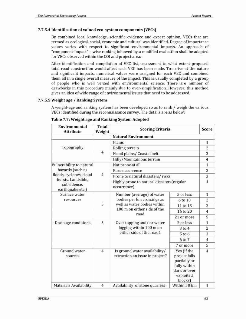
The Purvanchal Expressway Project Project Report
UPEIDA 62
7.7.5.4 Identification of valued ecosystem components (VECs) By combined local knowledge, scientific evidence and expert opinion, VECs that are termed as ecological, social, economic and cultural was identified. Degree of importance values varies with respect to significant environmental impacts. An approach of “component‐impact” – wise ranking followed by a modified evaluation shall be adapted for VECs observed within the COI and project area.
After identification and compilation of VEC list, assessment to what extent proposed total road construction would affect each VEC has been made. To arrive at the nature and significant impacts, numerical values were assigned for each VEC and combined them all in a single overall measure of the impact. This is usually completed by a group of people who is well versed with environmental science. There are number of drawbacks in this procedure mainly due to over‐simplification. However, this method gives an idea of wide range of environmental issues that need to be addressed.
7.7.5.5 Weight age / Ranking System A weight‐age and ranking system has been developed so as to rank / weigh the various VECs identified during the reconnaissance survey. The details are as below:
Table 7.7: Weight age and Ranking System Adopted
Environmental Attribute
Total Weight
Scoring Criteria Score
Natural Environment
Topography 4
Plains 1Rolling terrain 2Flood plains/ Coastal belt 3Hilly/Mountainous terrain 4
Vulnerability to natural hazards (such as
floods, cyclones, cloud bursts. Landslide,
subsidence, earthquake etc.)
4
Not prone at all 1Rare occurrence 2Prone to natural disasters/ risks 3Highly prone to natural disasters(regular occurrence)
4
Surface water resources
5
Number (average) of water bodies per km crossings as well as water bodies within 100 m on either side of the
road
5 or less 16 to 10 211 to 15 316 to 20 421 or more 5
Drainage conditions 5 Over topping and/ or water logging within 100 m on either side of the road1
2 or less 13 to 4 25 to 6 36 to 7 4
7 or more 5Ground water
sources 4 Is ground water availability/
extraction an issue in project? Yes (if the project falls partially or fully within dark or over exploited blocks)
4
Materials Availability 4 Availability of stone quarries Within 50 km 1
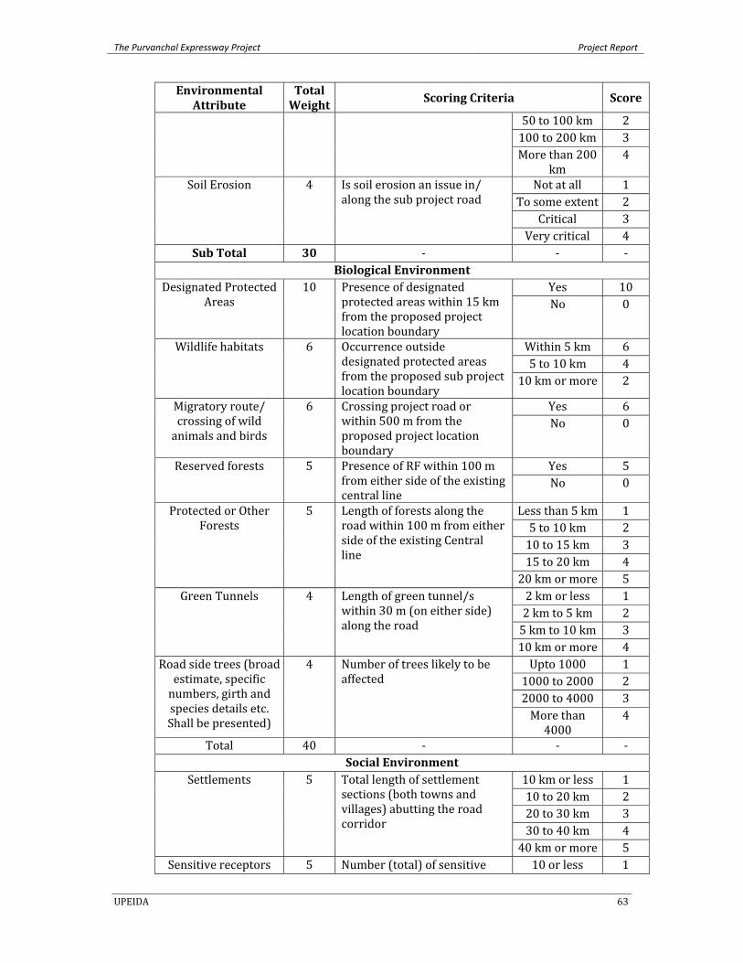
The Purvanchal Expressway Project Project Report
UPEIDA 63
Environmental Attribute
Total Weight
Scoring Criteria Score
50 to 100 km 2100 to 200 km 3More than 200
km 4
Soil Erosion 4 Is soil erosion an issue in/ along the sub project road
Not at all 1To some extent 2
Critical 3Very critical 4
Sub Total 30 ‐ ‐ ‐Biological Environment
Designated Protected Areas
10 Presence of designated protected areas within 15 km from the proposed project location boundary
Yes 10No 0
Wildlife habitats 6 Occurrence outside designated protected areas from the proposed sub project location boundary
Within 5 km 65 to 10 km 4
10 km or more 2
Migratory route/ crossing of wild animals and birds
6 Crossing project road or within 500 m from the proposed project location boundary
Yes 6No 0
Reserved forests 5 Presence of RF within 100 m from either side of the existing central line
Yes 5No 0
Protected or Other Forests
5 Length of forests along the road within 100 m from either side of the existing Central line
Less than 5 km 15 to 10 km 210 to 15 km 315 to 20 km 420 km or more 5
Green Tunnels 4 Length of green tunnel/s within 30 m (on either side) along the road
2 km or less 12 km to 5 km 25 km to 10 km 310 km or more 4
Road side trees (broad estimate, specific numbers, girth and species details etc. Shall be presented)
4 Number of trees likely to be affected
Upto 1000 11000 to 2000 22000 to 4000 3More than 4000
4
Total 40 ‐ ‐ ‐Social Environment
Settlements 5 Total length of settlement sections (both towns and villages) abutting the road corridor
10 km or less 110 to 20 km 220 to 30 km 330 to 40 km 440 km or more 5
Sensitive receptors 5 Number (total) of sensitive 10 or less 1
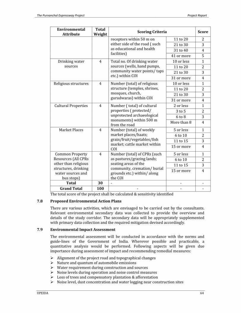
The Purvanchal Expressway Project Project Report
UPEIDA 64
Environmental Attribute
Total Weight
Scoring Criteria Score
receptors within 50 m on either side of the road ( such as educational and health facilities)
11 to 20 221 to 30 331 to 40 441 or more 5
Drinking water sources
4 Total no. Of drinking water sources (wells, hand pumps, community water points/ taps etc.) within COI
10 or less 111 to 20 221 to 30 331 or more 4
Religious structures 4 Number (total) of religious structure (temples, shrines, mosques, church, gurudwaras) within COI
10 or less 111 to 20 221 to 30 331 or more 4
Cultural Properties 4 Number ( total) of cultural properties ( protected/ unprotected archaeological monuments) within 500 m from the road
2 or less 13 to 5 26 to 8 3
More than 8 4
Market Places 4 Number (total) of weekly market places/haats; grain/fruit/vegetables/fish market; cattle market within COI
5 or less 16 to 10 211 to 15 315 or more 4
Common Property Resources (All CPRs other than religious structures, drinking water sources and
bus stops)
4 Number (total) of CPRs (such as pastures/grazing lands; seating areas of the community, cremation/ burial grounds etc.) within/ along the COI
5 or less 16 to 10 211 to 15 315 or more 4
Total 30 ‐ ‐ ‐Grand Total 100 ‐ ‐ ‐
The total score of the project shall be calculated & sensitivity identified
7.8 Proposed Environmental Action Plans
There are various activities, which are envisaged to be carried out by the consultants. Relevant environmental secondary data was collected to provide the overview and details of the study corridor. The secondary data will be appropriately supplemented with primary data collection and the required mitigation devised accordingly.
7.9 Environmental Impact Assessment
The environmental assessment will be conducted in accordance with the norms and guide‐lines of the Government of India. Wherever possible and practicable, a quantitative analysis would be performed. Following aspects will be given due importance during assessment of impact and recommending remedial measures:
Alignment of the project road and topographical changes Nature and quantum of automobile emissions Water requirement during construction and sources Noise levels during operation and noise control measures Loss of trees and compensatory plantation & afforestation Noise level, dust concentration and water logging near construction sites
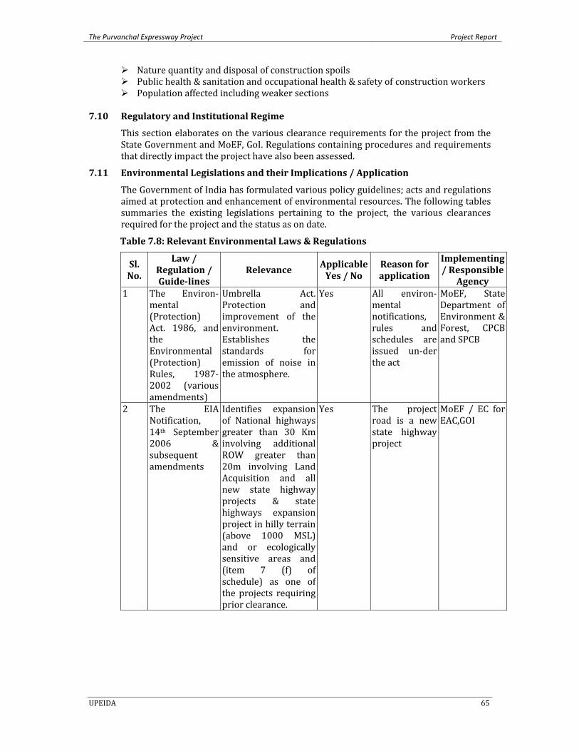
The Purvanchal Expressway Project Project Report
UPEIDA 65
Nature quantity and disposal of construction spoils Public health & sanitation and occupational health & safety of construction workers Population affected including weaker sections
7.10 Regulatory and Institutional Regime
This section elaborates on the various clearance requirements for the project from the State Government and MoEF, GoI. Regulations containing procedures and requirements that directly impact the project have also been assessed.
7.11 Environmental Legislations and their Implications / Application
The Government of India has formulated various policy guidelines; acts and regulations aimed at protection and enhancement of environmental resources. The following tables summaries the existing legislations pertaining to the project, the various clearances required for the project and the status as on date.
Table 7.8: Relevant Environmental Laws & Regulations
Sl. No.
Law / Regulation / Guidelines
Relevance Applicable Yes / No
Reason for application
Implementing / Responsible
Agency 1 The Environ‐
mental (Protection) Act. 1986, and the Environmental (Protection) Rules, 1987‐2002 (various amendments)
Umbrella Act. Protection and improvement of the environment. Establishes the standards for emission of noise in the atmosphere.
Yes All environ‐mental notifications, rules and schedules are issued un‐der the act
MoEF, State Department of Environment & Forest, CPCB and SPCB
2 The EIA Notification, 14th September 2006 & subsequent amendments
Identifies expansion of National highways greater than 30 Km involving additional ROW greater than 20m involving Land Acquisition and all new state highway projects & state highways expansion project in hilly terrain (above 1000 MSL) and or ecologically sensitive areas and (item 7 (f) of schedule) as one of the projects requiring prior clearance.
Yes The project road is a new state highway project
MoEF / EC for EAC,GOI
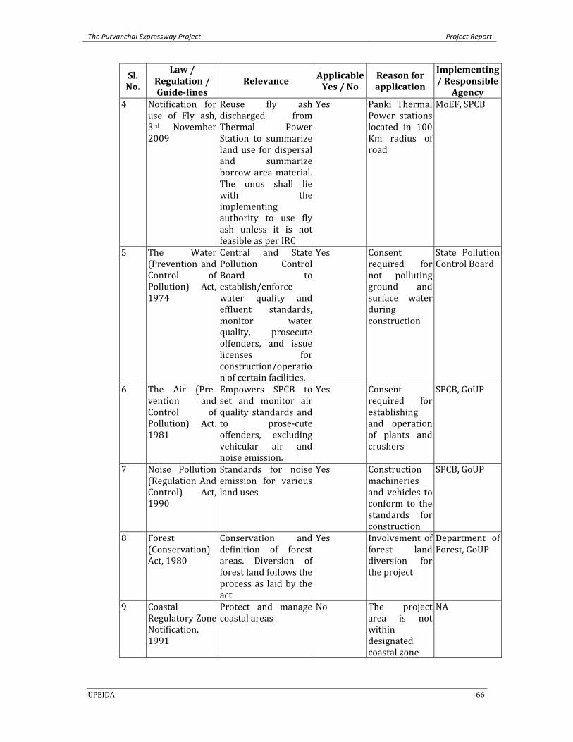
The Purvanchal Expressway Project Project Report
UPEIDA 66
Sl. No.
Law / Regulation / Guidelines
Relevance Applicable Yes / No
Reason for application
Implementing / Responsible
Agency 4 Notification for
use of Fly ash, 3rd November 2009
Reuse fly ash discharged from Thermal Power Station to summarize land use for dispersal and summarize borrow area material. The onus shall lie with the implementing authority to use fly ash unless it is not feasible as per IRC
Yes Panki Thermal Power stations located in 100 Km radius of road
MoEF, SPCB
5 The Water (Prevention and Control of Pollution) Act, 1974
Central and State Pollution Control Board to establish/enforce water quality and effluent standards, monitor water quality, prosecute offenders, and issue licenses for construction/operation of certain facilities.
Yes Consent required for not polluting ground and surface water during construction
State Pollution Control Board
6 The Air (Pre‐vention and Control of Pollution) Act. 1981
Empowers SPCB to set and monitor air quality standards and to prose‐cute offenders, excluding vehicular air and noise emission.
Yes Consent required for establishing and operation of plants and crushers
SPCB, GoUP
7 Noise Pollution (Regulation And Control) Act, 1990
Standards for noise emission for various land uses
Yes Construction machineries and vehicles to conform to the standards for construction
SPCB, GoUP
8 Forest (Conservation) Act, 1980
Conservation and definition of forest areas. Diversion of forest land follows the process as laid by the act
Yes Involvement of forest land diversion for the project
Department of Forest, GoUP
9 Coastal Regulatory Zone Notification, 1991
Protect and manage coastal areas
No The project area is not within designated coastal zone
NA
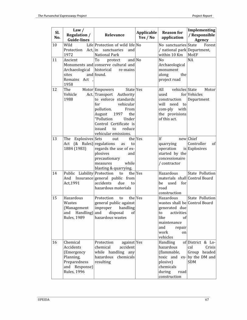
The Purvanchal Expressway Project Project Report
UPEIDA 67
Sl. No.
Law / Regulation / Guidelines
Relevance Applicable Yes / No
Reason for application
Implementing / Responsible
Agency 10 Wild Life
Protection Act, 1972
Protection of wild life in sanctuaries and National Park
No No sanctuaries / national park within 10 Km
State Forest Department, MoEF
11 Ancient Monuments and Archaeological sites and Remains Act , 1958
To protect and conserve cultural and historical re‐mains found.
No No Archaeological monument along the project road
NA
12 The Motor Vehicle Act. 1988
Empowers State Transport Authority to enforce standards for vehicular pollution. From August 1997 the “Pollution Under Control Certificate is issued to reduce vehicular emissions.
Yes All vehicles used for construction will need to com‐ply with the provisions of this act.
State Motor Vehicles Department
13 The Explosives Act (& Rules) 1884 (1983)
Sets out the regulations as to regards the use of ex‐plosives and precautionary measures while blasting & quarrying.
Yes If new quarrying operation is started by the concessionaire / contractor
Chief Controller of Explosives
14 Public Liability And Insurance Act,1991
Protection to the general public from accidents due to hazardous materials
Yes Hazardous materials shall be used for road construction
State Pollution Control Board
15 Hazardous Wastes (Management and Handling) Rules, 1989
Protection to the general public against improper handling and disposal of hazardous wastes
Yes Hazardous wastes shall be generated due to activities like of maintenance and repair work on vehicles
State Pollution Control Board
16 Chemical Accidents (Emergency Planning, Preparedness and Response) Rules, 1996
Protection against chemical accident while handling any hazardous chemicals resulting
Yes Handling of hazardous (flammable, toxic and ex‐plosive) chemicals during road construction
District & Lo‐cal Crisis Group headed by the DM and SDM
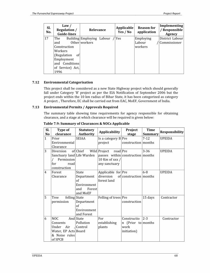
The Purvanchal Expressway Project Project Report
UPEIDA 68
Sl. No.
Law / Regulation / Guidelines
Relevance Applicable Yes / No
Reason for application
Implementing / Responsible
Agency 17 The Building
and Other Construction Workers (Regulation of Employment and Conditions of Service) Act, 1996
Employing Labour / workers
Yes Employing Labour / workers
District Labour Commissioner
7.12 Environmental Categorisation
This project shall be considered as a new State Highway project which should generally fall under Category ‘B’ project as per the EIA Notification of September 2006 but the project ends within the 10 km radius of Bihar State, it has been categorized as category A project. , Therefore, EC shall be carried out from EAC, MoEF, Government of India.
7.13 Environmental Permits / Approvals Required
The summary table showing time requirements for agency responsible for obtaining clearance, and a stage at which clearance will be required is given below:
Table 7.9: Summary of Clearances & NOCs Applicable
Sl. No
Type of clearance
Statutory Authority Applicability Project
stage Time
Summary Responsibility
1 Prior Environmental Clearance
SEIAA Is a category B project
Pre construction
7‐12 months
UPEIDA
3 Diversion of Sanctuary land / Permission for road construction
Chief Wild Life Warden
Project road passes within 10 Km of xxx / any sanctuary
Pre construction
3‐36 months
UPEIDA
4 Forest Clearance
State Department of Environment and Forest and MoEF
Applicable for diversion of forest land
Pre construction
6‐8 months
UPEIDA
5 Tree felling permission
State Department of Environment and Forest
Felling of trees Pre construction
15 days Contractor
6 NOC And Consents Under Air , Water, EP Acts & Noise rules of SPCB
State Pollution Control Board
For establishing plants
Construction (Prior to work initiation)
2‐3 months
Contractor
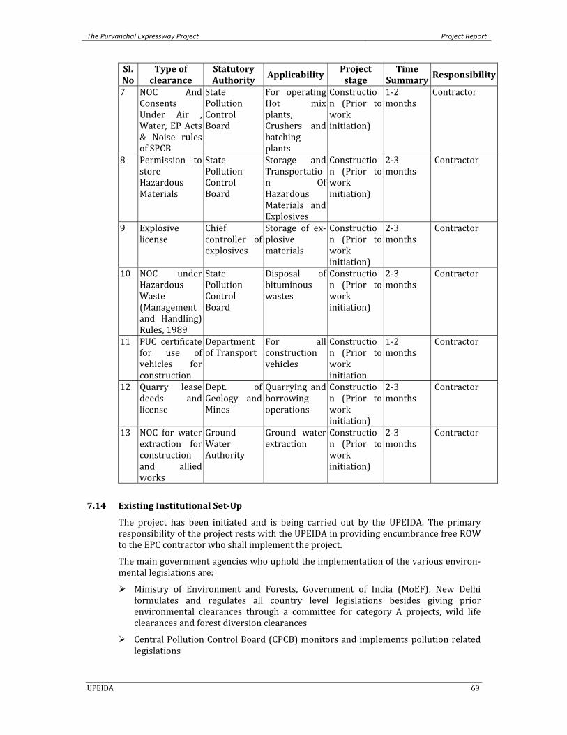
The Purvanchal Expressway Project Project Report
UPEIDA 69
Sl. No
Type of clearance
Statutory Authority Applicability
Project stage
Time Summary Responsibility
7 NOC And Consents Under Air , Water, EP Acts & Noise rules of SPCB
State Pollution Control Board
For operating Hot mix plants, Crushers and batching plants
Construction (Prior to work initiation)
1‐2 months
Contractor
8 Permission to store Hazardous Materials
State Pollution Control Board
Storage and Transportation Of Hazardous Materials and Explosives
Construction (Prior to work initiation)
2‐3 months
Contractor
9 Explosive license
Chief controller of explosives
Storage of ex‐plosive materials
Construction (Prior to work initiation)
2‐3 months
Contractor
10 NOC under Hazardous Waste (Management and Handling) Rules, 1989
State Pollution Control Board
Disposal of bituminous wastes
Construction (Prior to work initiation)
2‐3 months
Contractor
11 PUC certificate for use of vehicles for construction
Department of Transport
For all construction vehicles
Construction (Prior to work initiation
1‐2 months
Contractor
12 Quarry lease deeds and license
Dept. of Geology and Mines
Quarrying and borrowing operations
Construction (Prior to work initiation)
2‐3 months
Contractor
13 NOC for water extraction for construction and allied works
Ground Water Authority
Ground water extraction
Construction (Prior to work initiation)
2‐3 months
Contractor
7.14 Existing Institutional SetUp
The project has been initiated and is being carried out by the UPEIDA. The primary responsibility of the project rests with the UPEIDA in providing encumbrance free ROW to the EPC contractor who shall implement the project.
The main government agencies who uphold the implementation of the various environ‐mental legislations are:
Ministry of Environment and Forests, Government of India (MoEF), New Delhi formulates and regulates all country level legislations besides giving prior environmental clearances through a committee for category A projects, wild life clearances and forest diversion clearances
Central Pollution Control Board (CPCB) monitors and implements pollution related legislations
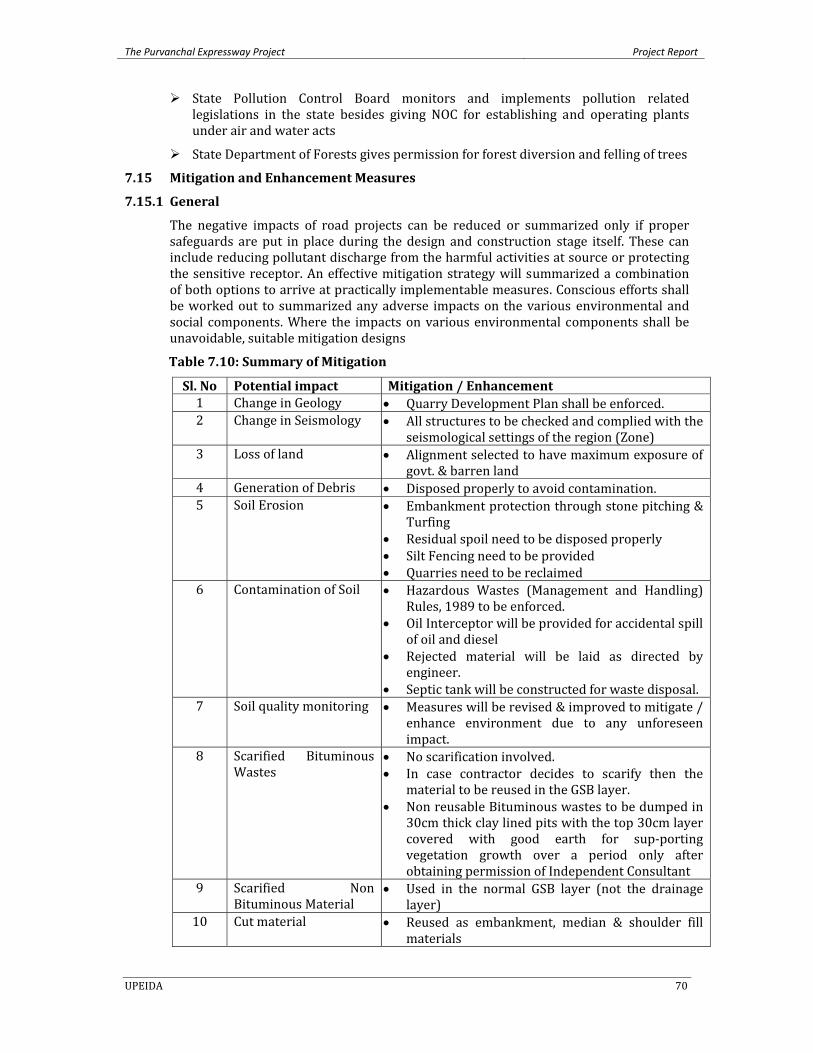
The Purvanchal Expressway Project Project Report
UPEIDA 70
State Pollution Control Board monitors and implements pollution related legislations in the state besides giving NOC for establishing and operating plants under air and water acts
State Department of Forests gives permission for forest diversion and felling of trees
7.15 Mitigation and Enhancement Measures
7.15.1 General The negative impacts of road projects can be reduced or summarized only if proper safeguards are put in place during the design and construction stage itself. These can include reducing pollutant discharge from the harmful activities at source or protecting the sensitive receptor. An effective mitigation strategy will summarized a combination of both options to arrive at practically implementable measures. Conscious efforts shall be worked out to summarized any adverse impacts on the various environmental and social components. Where the impacts on various environmental components shall be unavoidable, suitable mitigation designs
Table 7.10: Summary of Mitigation
Sl. No Potential impact Mitigation / Enhancement 1 Change in Geology • Quarry Development Plan shall be enforced. 2 Change in Seismology • All structures to be checked and complied with the
seismological settings of the region (Zone) 3 Loss of land • Alignment selected to have maximum exposure of
govt. & barren land 4 Generation of Debris • Disposed properly to avoid contamination. 5 Soil Erosion • Embankment protection through stone pitching &
Turfing • Residual spoil need to be disposed properly • Silt Fencing need to be provided • Quarries need to be reclaimed
6 Contamination of Soil • Hazardous Wastes (Management and Handling) Rules, 1989 to be enforced.
• Oil Interceptor will be provided for accidental spill of oil and diesel
• Rejected material will be laid as directed by engineer.
• Septic tank will be constructed for waste disposal. 7 Soil quality monitoring • Measures will be revised & improved to mitigate /
enhance environment due to any unforeseen impact.
8 Scarified Bituminous Wastes
• No scarification involved. • In case contractor decides to scarify then the
material to be reused in the GSB layer. • Non reusable Bituminous wastes to be dumped in
30cm thick clay lined pits with the top 30cm layer covered with good earth for sup‐porting vegetation growth over a period only after obtaining permission of Independent Consultant
9 Scarified Non Bituminous Material
• Used in the normal GSB layer (not the drainage layer)
10 Cut material • Reused as embankment, median & shoulder fill materials
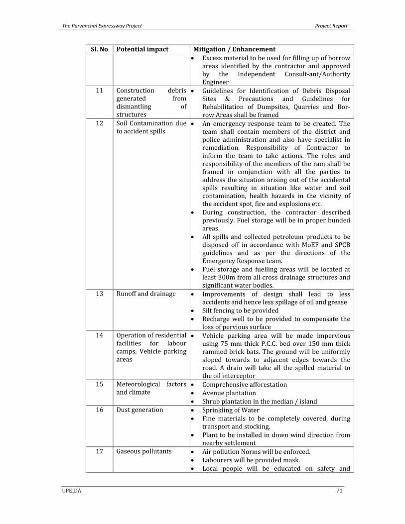
The Purvanchal Expressway Project Project Report
UPEIDA 71
Sl. No Potential impact Mitigation / Enhancement • Excess material to be used for filling up of borrow
areas identified by the contractor and approved by the Independent Consult‐ant/Authority Engineer
11 Construction debris generated from dismantling of structures
• Guidelines for Identification of Debris Disposal Sites & Precautions and Guidelines for Rehabilitation of Dumpsites, Quarries and Bor‐row Areas shall be framed
12 Soil Contamination due to accident spills
• An emergency response team to be created. The team shall contain members of the district and police administration and also have specialist in remediation. Responsibility of Contractor to inform the team to take actions. The roles and responsibility of the members of the ram shall be framed in conjunction with all the parties to address the situation arising out of the accidental spills resulting in situation like water and soil contamination, health hazards in the vicinity of the accident spot, fire and explosions etc.
• During construction, the contractor described previously. Fuel storage will be in proper bunded areas.
• All spills and collected petroleum products to be disposed off in accordance with MoEF and SPCB guidelines and as per the directions of the Emergency Response team.
• Fuel storage and fuelling areas will be located at least 300m from all cross drainage structures and significant water bodies.
13 Runoff and drainage • Improvements of design shall lead to less accidents and hence less spillage of oil and grease
• Silt fencing to be provided • Recharge well to be provided to compensate the
loss of pervious surface 14 Operation of residential
facilities for labour camps, Vehicle parking areas
• Vehicle parking area will be made impervious using 75 mm thick P.C.C. bed over 150 mm thick rammed brick bats. The ground will be uniformly sloped towards to adjacent edges towards the road. A drain will take all the spilled material to the oil interceptor
15 Meteorological factors and climate
• Comprehensive afforestation • Avenue plantation • Shrub plantation in the median / island
16 Dust generation • Sprinkling of Water • Fine materials to be completely covered, during
transport and stocking. • Plant to be installed in down wind direction from
nearby settlement 17 Gaseous pollutants • Air pollution Norms will be enforced.
• Labourers will be provided mask. • Local people will be educated on safety and
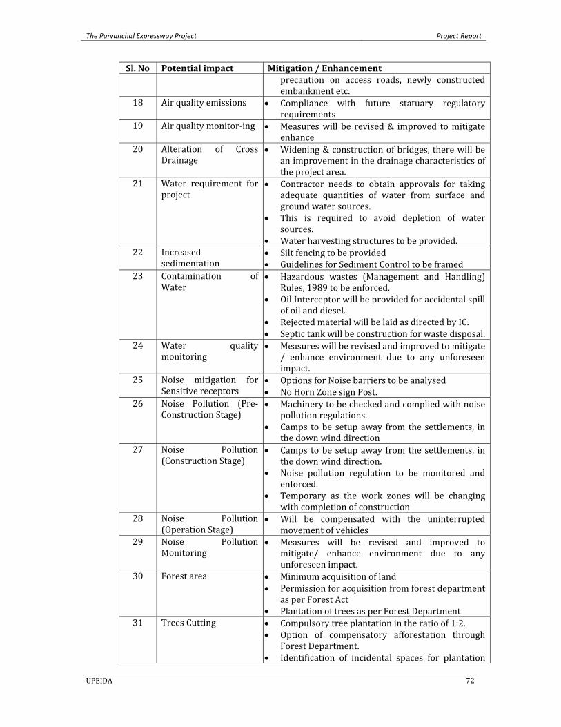
The Purvanchal Expressway Project Project Report
UPEIDA 72
Sl. No Potential impact Mitigation / Enhancement precaution on access roads, newly constructed embankment etc.
18 Air quality emissions • Compliance with future statuary regulatory requirements
19 Air quality monitor‐ing • Measures will be revised & improved to mitigate enhance
20 Alteration of Cross Drainage
• Widening & construction of bridges, there will be an improvement in the drainage characteristics of the project area.
21 Water requirement for project
• Contractor needs to obtain approvals for taking adequate quantities of water from surface and ground water sources.
• This is required to avoid depletion of water sources.
• Water harvesting structures to be provided. 22 Increased
sedimentation • Silt fencing to be provided • Guidelines for Sediment Control to be framed
23 Contamination of Water
• Hazardous wastes (Management and Handling) Rules, 1989 to be enforced.
• Oil Interceptor will be provided for accidental spill of oil and diesel.
• Rejected material will be laid as directed by IC. • Septic tank will be construction for waste disposal.
24 Water quality monitoring
• Measures will be revised and improved to mitigate / enhance environment due to any unforeseen impact.
25 Noise mitigation for Sensitive receptors
• Options for Noise barriers to be analysed • No Horn Zone sign Post.
26 Noise Pollution (Pre‐Construction Stage)
• Machinery to be checked and complied with noise pollution regulations.
• Camps to be setup away from the settlements, in the down wind direction
27 Noise Pollution (Construction Stage)
• Camps to be setup away from the settlements, in the down wind direction.
• Noise pollution regulation to be monitored and enforced.
• Temporary as the work zones will be changing with completion of construction
28 Noise Pollution (Operation Stage)
• Will be compensated with the uninterrupted movement of vehicles
29 Noise Pollution Monitoring
• Measures will be revised and improved to mitigate/ enhance environment due to any unforeseen impact.
30 Forest area • Minimum acquisition of land • Permission for acquisition from forest department
as per Forest Act • Plantation of trees as per Forest Department
31 Trees Cutting • Compulsory tree plantation in the ratio of 1:2. • Option of compensatory afforestation through
Forest Department. • Identification of incidental spaces for plantation
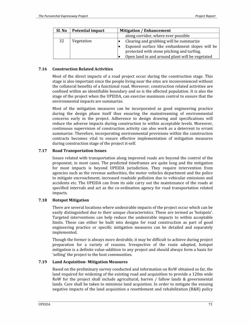
The Purvanchal Expressway Project Project Report
UPEIDA 73
Sl. No Potential impact Mitigation / Enhancement along corridor, where ever possible
32 Vegetation • Clearing and grubbing will be summarize • Exposed surface like embankment slopes will be
protected with stone pitching and turfing. • Open land in and around plant will be vegetated
7.16 Construction Related Activities
Most of the direct impacts of a road project occur during the construction stage. This stage is also important since the people living near the sites are inconvenienced without the collateral benefits of a functional road. Moreover, construction related activities are confined within an identifiable boundary and so is the affected population. It is also the stage of the project when the UPEIDA, can exercise maximum control to ensure that the environmental impacts are summarize.
Most of the mitigation measures can be incorporated as good engineering practice during the design phase itself thus ensuring the mainstreaming of environmental concerns early in the project. Adherence to design drawing and specifications will reduce the adverse impacts during construction to within acceptable levels. Moreover, continuous supervision of construction activity can also work as a deterrent to errant summarize. Therefore, incorporating environmental provisions within the construction contracts becomes vital to ensure effective implementation of mitigation measures during construction stage of the project it‐self.
7.17 Road Transportation Issues
Issues related with transportation along improved roads are beyond the control of the proponent, in most cases. The predicted timeframes are quite long and the mitigation for most impacts is beyond UPEIDA jurisdiction. They require intervention from agencies such as the revenue authorities, the motor vehicles department and the police to mitigate encroachment, increased roadside pollution due to vehicular emissions and accidents etc. The UPEIDA can from its side carry out the maintenance of the roads at specified intervals and act as the co‐ordination agency for road transportation related impacts.
7.18 Hotspot Mitigation
There are several locations where undesirable impacts of the project occur which can be easily distinguished due to their unique characteristics. These are termed as ‘hotspots’. Targeted interventions can help reduce the undesirable impacts to within acceptable limits. These can either be built into designs for road construction as part of good engineering practice or specific mitigation measures can be detailed and separately implemented.
Though the former is always more desirable, it may be difficult to achieve during project preparation for a variety of reasons. Irrespective of the route adopted, hotspot mitigation is a definite value‐addition to any project and should always form a basis for ‘selling’ the project to the host communities.
7.19 Land Acquisition Mitigation Measures
Based on the preliminary survey conducted and information on RoW obtained so far, the land required for widening of the existing road and acquisition to provide a 120m wide RoW for the project shall include agricultural, barren / fallow lands & governmental lands. Care shall be taken to minimize land acquistion. In order to mitigate the ensuing negative impacts of the land acquisition a resettlement and rehabilitation (R&R) policy
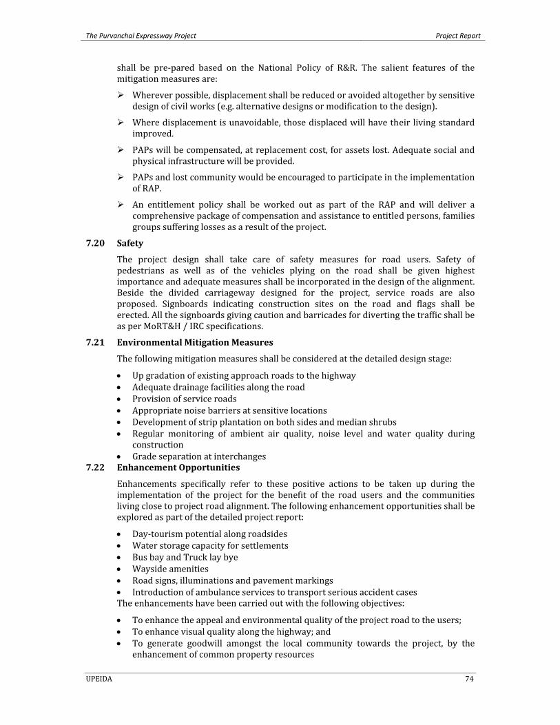
The Purvanchal Expressway Project Project Report
UPEIDA 74
shall be pre‐pared based on the National Policy of R&R. The salient features of the mitigation measures are:
Wherever possible, displacement shall be reduced or avoided altogether by sensitive design of civil works (e.g. alternative designs or modification to the design).
Where displacement is unavoidable, those displaced will have their living standard improved.
PAPs will be compensated, at replacement cost, for assets lost. Adequate social and physical infrastructure will be provided.
PAPs and lost community would be encouraged to participate in the implementation of RAP.
An entitlement policy shall be worked out as part of the RAP and will deliver a comprehensive package of compensation and assistance to entitled persons, families groups suffering losses as a result of the project.
7.20 Safety
The project design shall take care of safety measures for road users. Safety of pedestrians as well as of the vehicles plying on the road shall be given highest importance and adequate measures shall be incorporated in the design of the alignment. Beside the divided carriageway designed for the project, service roads are also proposed. Signboards indicating construction sites on the road and flags shall be erected. All the signboards giving caution and barricades for diverting the traffic shall be as per MoRT&H / IRC specifications.
7.21 Environmental Mitigation Measures
The following mitigation measures shall be considered at the detailed design stage:
• Up gradation of existing approach roads to the highway • Adequate drainage facilities along the road • Provision of service roads • Appropriate noise barriers at sensitive locations • Development of strip plantation on both sides and median shrubs • Regular monitoring of ambient air quality, noise level and water quality during
construction • Grade separation at interchanges
7.22 Enhancement Opportunities
Enhancements specifically refer to these positive actions to be taken up during the implementation of the project for the benefit of the road users and the communities living close to project road alignment. The following enhancement opportunities shall be explored as part of the detailed project report:
• Day‐tourism potential along roadsides • Water storage capacity for settlements • Bus bay and Truck lay bye • Wayside amenities • Road signs, illuminations and pavement markings • Introduction of ambulance services to transport serious accident cases The enhancements have been carried out with the following objectives:
• To enhance the appeal and environmental quality of the project road to the users; • To enhance visual quality along the highway; and • To generate goodwill amongst the local community towards the project, by the
enhancement of common property resources
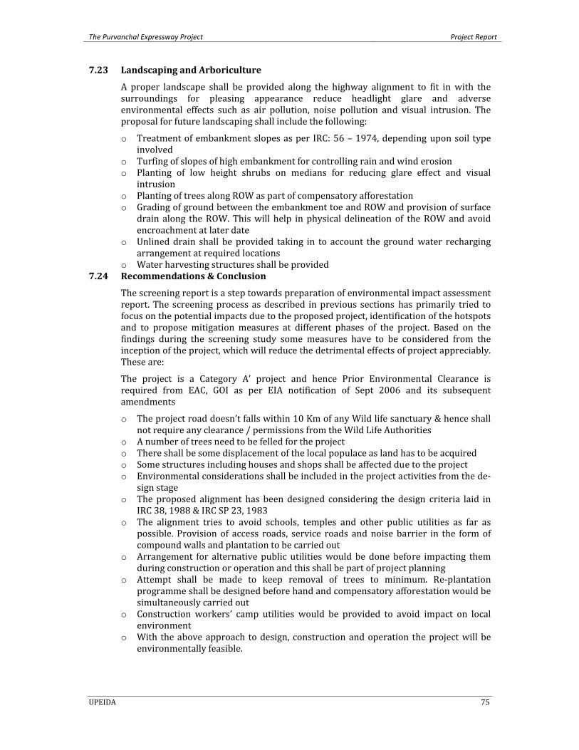
The Purvanchal Expressway Project Project Report
UPEIDA 75
7.23 Landscaping and Arboriculture
A proper landscape shall be provided along the highway alignment to fit in with the surroundings for pleasing appearance reduce headlight glare and adverse environmental effects such as air pollution, noise pollution and visual intrusion. The proposal for future landscaping shall include the following:
o Treatment of embankment slopes as per IRC: 56 – 1974, depending upon soil type involved
o Turfing of slopes of high embankment for controlling rain and wind erosion o Planting of low height shrubs on medians for reducing glare effect and visual
intrusion o Planting of trees along ROW as part of compensatory afforestation o Grading of ground between the embankment toe and ROW and provision of surface
drain along the ROW. This will help in physical delineation of the ROW and avoid encroachment at later date
o Unlined drain shall be provided taking in to account the ground water recharging arrangement at required locations
o Water harvesting structures shall be provided 7.24 Recommendations & Conclusion
The screening report is a step towards preparation of environmental impact assessment report. The screening process as described in previous sections has primarily tried to focus on the potential impacts due to the proposed project, identification of the hotspots and to propose mitigation measures at different phases of the project. Based on the findings during the screening study some measures have to be considered from the inception of the project, which will reduce the detrimental effects of project appreciably. These are:
The project is a Category A’ project and hence Prior Environmental Clearance is required from EAC, GOI as per EIA notification of Sept 2006 and its subsequent amendments
o The project road doesn’t falls within 10 Km of any Wild life sanctuary & hence shall not require any clearance / permissions from the Wild Life Authorities
o A number of trees need to be felled for the project o There shall be some displacement of the local populace as land has to be acquired o Some structures including houses and shops shall be affected due to the project o Environmental considerations shall be included in the project activities from the de‐
sign stage o The proposed alignment has been designed considering the design criteria laid in
IRC 38, 1988 & IRC SP 23, 1983 o The alignment tries to avoid schools, temples and other public utilities as far as
possible. Provision of access roads, service roads and noise barrier in the form of compound walls and plantation to be carried out
o Arrangement for alternative public utilities would be done before impacting them during construction or operation and this shall be part of project planning
o Attempt shall be made to keep removal of trees to minimum. Re‐plantation programme shall be designed before hand and compensatory afforestation would be simultaneously carried out
o Construction workers’ camp utilities would be provided to avoid impact on local environment
o With the above approach to design, construction and operation the project will be environmentally feasible.
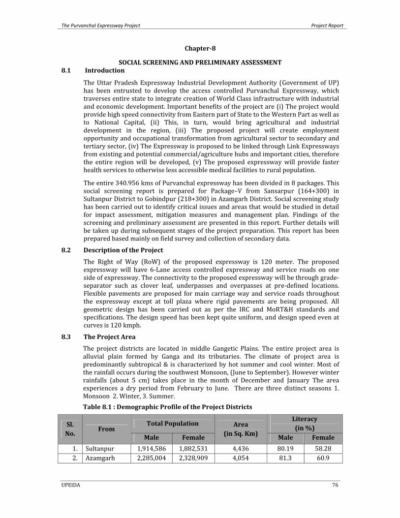
The Purvanchal Expressway Project Project Report
UPEIDA 76
Chapter8
SOCIAL SCREENING AND PRELIMINARY ASSESSMENT 8.1 Introduction
The Uttar Pradesh Expressway Industrial Development Authority (Government of UP) has been entrusted to develop the access controlled Purvanchal Expressway, which traverses entire state to integrate creation of World Class infrastructure with industrial and economic development. Important benefits of the project are (i) The project would provide high speed connectivity from Eastern part of State to the Western Part as well as to National Capital, (ii) This, in turn, would bring agricultural and industrial development in the region, (iii) The proposed project will create employment opportunity and occupational transformation from agricultural sector to secondary and tertiary sector, (iv) The Expressway is proposed to be linked through Link Expressways from existing and potential commercial/agriculture hubs and important cities, therefore the entire region will be developed, (v) The proposed expressway will provide faster health services to otherwise less accessible medical facilities to rural population.
The entire 340.956 kms of Purvanchal expressway has been divided in 8 packages. This social screening report is prepared for Package–V from Sansarpur (164+300) in Sultanpur District to Gobindpur (218+300) in Azamgarh District. Social screening study has been carried out to identify critical issues and areas that would be studied in detail for impact assessment, mitigation measures and management plan. Findings of the screening and preliminary assessment are presented in this report. Further details will be taken up during subsequent stages of the project preparation. This report has been prepared based mainly on field survey and collection of secondary data.
8.2 Description of the Project
The Right of Way (RoW) of the proposed expressway is 120 meter. The proposed expressway will have 6‐Lane access controlled expressway and service roads on one side of expressway. The connectivity to the proposed expressway will be through grade‐separator such as clover leaf, underpasses and overpasses at pre‐defined locations. Flexible pavements are proposed for main carriage way and service roads throughout the expressway except at toll plaza where rigid pavements are being proposed. All geometric design has been carried out as per the IRC and MoRT&H standards and specifications. The design speed has been kept quite uniform, and design speed even at curves is 120 kmph.
8.3 The Project Area
The project districts are located in middle Gangetic Plains. The entire project area is alluvial plain formed by Ganga and its tributaries. The climate of project area is predominantly subtropical & is characterized by hot summer and cool winter. Most of the rainfall occurs during the southwest Monsoon, (June to September). However winter rainfalls (about 5 cm) takes place in the month of December and January The area experiences a dry period from February to June. There are three distinct seasons 1. Monsoon 2. Winter, 3. Summer.
Table 8.1 : Demographic Profile of the Project Districts
Sl. No.
From Total Population Area
(in Sq. Km)
Literacy (in %)
Male Female Male Female
1. Sultanpur 1,914,586 1,882,531 4,436 80.19 58.28 2. Azamgarh 2,285,004 2,328,909 4,054 81.3 60.9
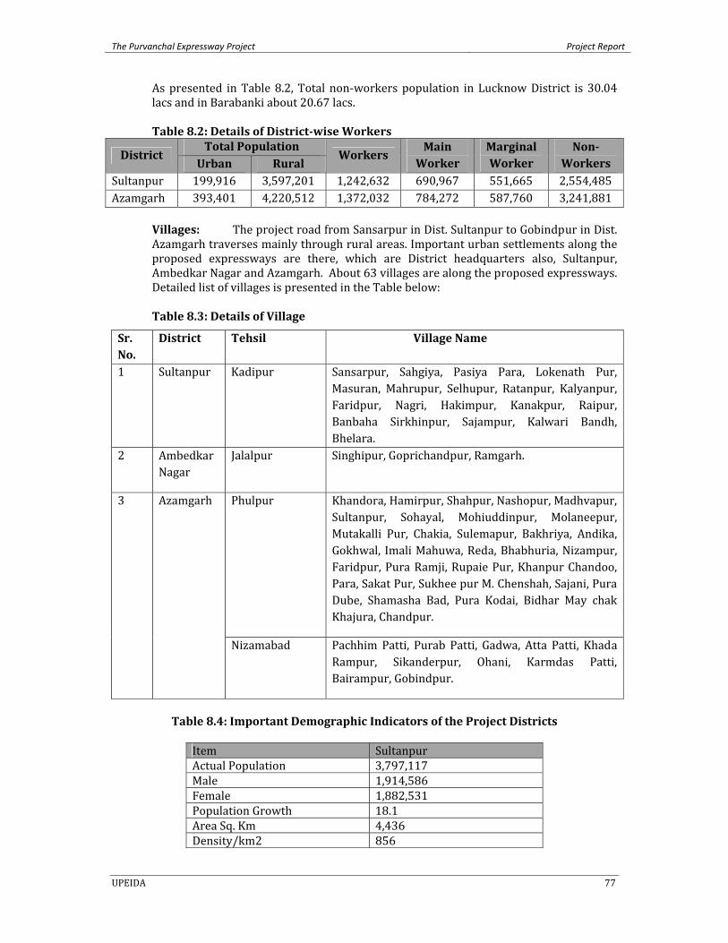
The Purvanchal Expressway Project Project Report
UPEIDA 77
As presented in Table 8.2, Total non‐workers population in Lucknow District is 30.04 lacs and in Barabanki about 20.67 lacs.
Table 8.2: Details of Districtwise Workers
District Total Population
Workers Main Worker
Marginal Worker
Non Workers Urban Rural
Sultanpur 199,916 3,597,201 1,242,632 690,967 551,665 2,554,485 Azamgarh 393,401 4,220,512 1,372,032 784,272 587,760 3,241,881
Villages: The project road from Sansarpur in Dist. Sultanpur to Gobindpur in Dist. Azamgarh traverses mainly through rural areas. Important urban settlements along the proposed expressways are there, which are District headquarters also, Sultanpur, Ambedkar Nagar and Azamgarh. About 63 villages are along the proposed expressways. Detailed list of villages is presented in the Table below: Table 8.3: Details of Village
Sr. No.
District Tehsil Village Name
1 Sultanpur Kadipur Sansarpur, Sahgiya, Pasiya Para, Lokenath Pur, Masuran, Mahrupur, Selhupur, Ratanpur, Kalyanpur, Faridpur, Nagri, Hakimpur, Kanakpur, Raipur, Banbaha Sirkhinpur, Sajampur, Kalwari Bandh, Bhelara.
2 Ambedkar Nagar
Jalalpur Singhipur, Goprichandpur, Ramgarh.
3 Azamgarh Phulpur Khandora, Hamirpur, Shahpur, Nashopur, Madhvapur, Sultanpur, Sohayal, Mohiuddinpur, Molaneepur, Mutakalli Pur, Chakia, Sulemapur, Bakhriya, Andika, Gokhwal, Imali Mahuwa, Reda, Bhabhuria, Nizampur, Faridpur, Pura Ramji, Rupaie Pur, Khanpur Chandoo, Para, Sakat Pur, Sukhee pur M. Chenshah, Sajani, Pura Dube, Shamasha Bad, Pura Kodai, Bidhar May chak Khajura, Chandpur.
Nizamabad Pachhim Patti, Purab Patti, Gadwa, Atta Patti, Khada Rampur, Sikanderpur, Ohani, Karmdas Patti, Bairampur, Gobindpur.
Table 8.4: Important Demographic Indicators of the Project Districts
Item SultanpurActual Population 3,797,117Male 1,914,586Female 1,882,531Population Growth 18.1Area Sq. Km 4,436Density/km2 856
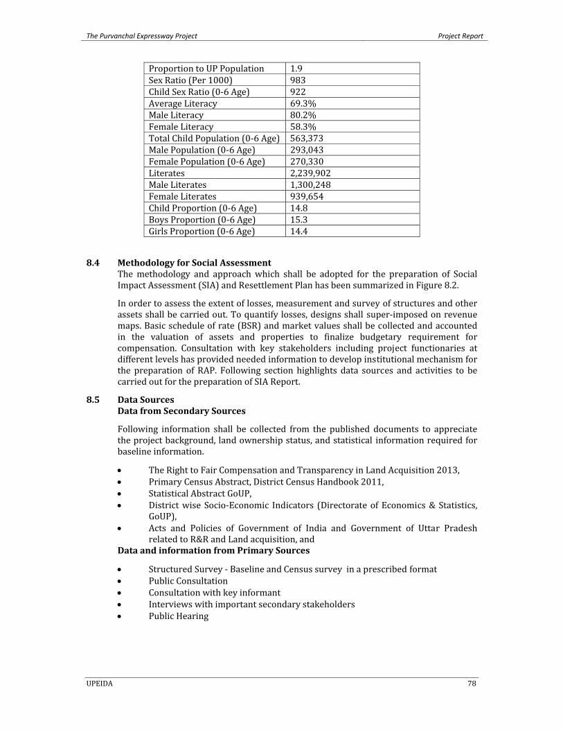
The Purvanchal Expressway Project Project Report
UPEIDA 78
Proportion to UP Population 1.9Sex Ratio (Per 1000) 983Child Sex Ratio (0‐6 Age) 922Average Literacy 69.3%Male Literacy 80.2%Female Literacy 58.3%Total Child Population (0‐6 Age) 563,373Male Population (0‐6 Age) 293,043Female Population (0‐6 Age) 270,330Literates 2,239,902Male Literates 1,300,248Female Literates 939,654Child Proportion (0‐6 Age) 14.8Boys Proportion (0‐6 Age) 15.3Girls Proportion (0‐6 Age) 14.4
8.4 Methodology for Social Assessment The methodology and approach which shall be adopted for the preparation of Social Impact Assessment (SIA) and Resettlement Plan has been summarized in Figure 8.2.
In order to assess the extent of losses, measurement and survey of structures and other assets shall be carried out. To quantify losses, designs shall super‐imposed on revenue maps. Basic schedule of rate (BSR) and market values shall be collected and accounted in the valuation of assets and properties to finalize budgetary requirement for compensation. Consultation with key stakeholders including project functionaries at different levels has provided needed information to develop institutional mechanism for the preparation of RAP. Following section highlights data sources and activities to be carried out for the preparation of SIA Report.
8.5 Data Sources Data from Secondary Sources
Following information shall be collected from the published documents to appreciate the project background, land ownership status, and statistical information required for baseline information.
• The Right to Fair Compensation and Transparency in Land Acquisition 2013, • Primary Census Abstract, District Census Handbook 2011, • Statistical Abstract GoUP, • District wise Socio‐Economic Indicators (Directorate of Economics & Statistics,
GoUP), • Acts and Policies of Government of India and Government of Uttar Pradesh
related to R&R and Land acquisition, and Data and information from Primary Sources
• Structured Survey ‐ Baseline and Census survey in a prescribed format • Public Consultation • Consultation with key informant • Interviews with important secondary stakeholders • Public Hearing
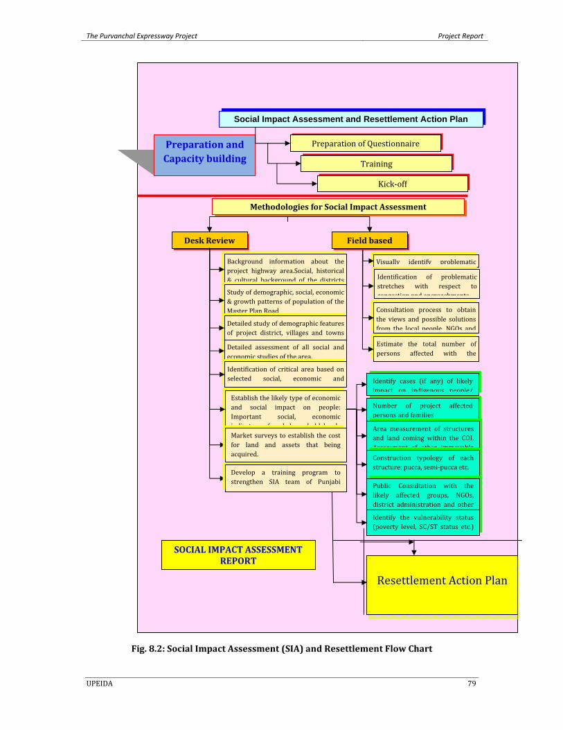
The Purvanchal Expressway Project Project Report
UPEIDA 79
Fig. 8.2: Social Impact Assessment (SIA) and Resettlement Flow Chart
Detailed assessment of all social and economic studies of the area.
Desk Review
Social Impact Assessment and Resettlement Action Plan
Preparation of Questionnaire
Training
Kick‐off
Preparation and Capacity building
Methodologies for Social Impact Assessment
Background information about the project highway area.Social, historical & cultural background of the districts
Study of demographic, social, economic & growth patterns of population of the Master Plan Road
Detailed study of demographic features of project district, villages and towns
Visually identify problematic
Identification of critical area based on selected social, economic and
Identification of problematic stretches with respect to congestion and encroachments
Consultation process to obtain the views and possible solutions from the local people, NGOs and
Estimate the total number of persons affected with the
Establish the likely type of economic and social impact on people: Important social, economic indicators of each household levels
Identify cases (if any) of likely impact on indigenous people/
Number of project affected persons and families
Area measurement of structures and land coming within the COI. Assessment of other immovableConstruction typology of each structure: pucca, semi‐pucca etc.
Identify the vulnerability status (poverty level, SC/ST status etc.)
Public Consultation with the likely affected groups, NGOs, district administration and other
Market surveys to establish the cost for land and assets that being acquired.
Field based
Develop a training program to strengthen SIA team of Punjabi U i i
Resettlement Action Plan
SOCIAL IMPACT ASSESSMENT REPORT
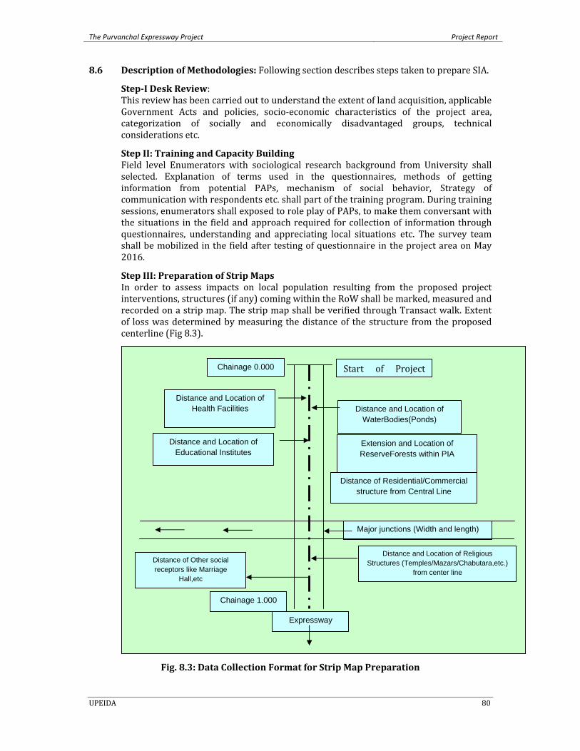
The Purvanchal Expressway Project Project Report
UPEIDA 80
8.6 Description of Methodologies: Following section describes steps taken to prepare SIA.
StepI Desk Review: This review has been carried out to understand the extent of land acquisition, applicable Government Acts and policies, socio‐economic characteristics of the project area, categorization of socially and economically disadvantaged groups, technical considerations etc.
Step II: Training and Capacity Building Field level Enumerators with sociological research background from University shall selected. Explanation of terms used in the questionnaires, methods of getting information from potential PAPs, mechanism of social behavior, Strategy of communication with respondents etc. shall part of the training program. During training sessions, enumerators shall exposed to role play of PAPs, to make them conversant with the situations in the field and approach required for collection of information through questionnaires, understanding and appreciating local situations etc. The survey team shall be mobilized in the field after testing of questionnaire in the project area on May 2016.
Step III: Preparation of Strip Maps In order to assess impacts on local population resulting from the proposed project interventions, structures (if any) coming within the RoW shall be marked, measured and recorded on a strip map. The strip map shall be verified through Transact walk. Extent of loss was determined by measuring the distance of the structure from the proposed centerline (Fig 8.3).
Fig. 8.3: Data Collection Format for Strip Map Preparation
Start of Project Chainage 0.000
Distance and Location of WaterBodies(Ponds)
Distance and Location of Health Facilities
Distance and Location of Educational Institutes
Extension and Location of ReserveForests within PIA
Distance of Residential/Commercial structure from Central Line
Major junctions (Width and length)
Distance and Location of Religious Structures (Temples/Mazars/Chabutara,etc.)
from center line Distance of Other social receptors like Marriage
Hall,etc
Chainage 1.000
Expressway i
The Purvanchal Expressway Project Project Report
UPEIDA 81
Step IV: Identification of Affected Land For identification of the affected lands and potential PAFs, Social teams shall visit to the Expressways alignment along with the drawings of the proposed expressways true to scale and Sajara (revenue) maps for site verification. The corridor of impact (proposed RoW(120 m) for road construction) shall be marked in the field at 100m intervals in straight portion and 50 meters interval at curves. Accordingly, proposed Corridor of Impact (CoI) shall be superimposed on Sajara map to assess the exact extent of land required to be acquired/appropriated. This included measurement of Center line from the fixed boundary stone of villages in the field and from the fixed location of boundary stone as shown in Sajara map (coordinates of village maps). On identification of affected plots of land and owner, the social teams will visit the household for survey. Step V: Census and Baseline Survey On identification of actual impacts and list of affected persons (titled and non‐ titled), questionnaires shall designed for the Census Survey and baseline socioeconomic survey. These formats shall be canvassed with the potentially affected people. The questionnaires included details regarding social and economic aspects of the affected persons such as demographic features (age sex composition, marital status etc) and economic information (occupation, sources of income, movable and immovable assets) of the households, expected losses(loss of residential/commercial or other properties as well as type of structure (such as pucca, semi pucca, kuccha) and options/preferences for their R&R (like cash in lieu of losses or site in lieu of losses).
While census survey has established actual impact on the project affected families in terms of severity, perception and R&R option for resettlement and rehabilitation, socio‐economic survey helped in profiling socio‐economic conditions of the PAFs .
Step VI: Stakeholders’ Consultation Stakeholders’ consultation was initiated as soon as the assessment process commenced. Consultation shall be planned to understand peoples’ perception and seek their opinion for the success of project execution. Consultation is also an important tool to gather qualitative data which helps in improving quality of planning. Following steps have been followed during stakeholders’ consultations.
• Identification of key stakeholders • Deciding on the level of consultation • Identification of mechanism and tools of consultation • Information dissemination through Pamphlet distribution • Meetings with people in groups,, individual meetings/interviews • Developing sense of ownership of project interventions among the stakeholders • Planning for consultation and communication strategies • Ensuring field offices as centers of information about the project during the
preparation phase • Properly documenting all consultations
Focused Group Discussions: Besides above mentioned consultation mechanism, the project will emphasize on issues based discussions with the stakeholders. Important issues discussed shall the specific needs of women and other vulnerable groups, policies and other interventions required for LA, strategies for developing harmonious relationship among various stakeholder including UPEIDA and project authorities.
Step VII Analysis of Data The interview schedules filled up every day shall be scrutinized and verified on the spot (project corridor) and the data‐sheets shall be coded. A coding manual shall be prepared
The Purvanchal Expressway Project Project Report
UPEIDA 82
for consistency in data entry. The MS‐Excel and MS‐Excess software package shall be used for the data feeding and its analysis. Wherever applicable, SPS package will also used to generate tables. As a measure of final confirmation about the correctness of the data, random manual calculations and checking shall also be done.
8.7 Land Acquisition Since, the project is proposed to be a green field alignment with proposed RoW is 120 m. Total land required for the construction of Highways would be about 632.713 ha (for expressway, Junction, way side amenities and toilet block).
8.8 Mitigation Measures
The negative impacts of road projects can be reduced or minimised only if proper safeguards are put in place during the design and construction stage itself. These can include reducing displacement from the project activities. An effective mitigation strategy will utilise a combination of both options to arrive at practically implementable measures. Conscious efforts shall be worked out to minimise any adverse impacts on the various Social components. Where the impacts on various Social components shall be unavoidable, suitable mitigation designs shall be worked out.
8.9 Construction related activities
Most of the direct impacts of a road project occur during the construction stage. This stage is also important since the people living near the sites are inconvenienced without the collateral benefits of a functional road. Moreover, construction related activities are confined within an identifiable boundary and so is the affected population. It is also the stage of the project when the Authority, can exercise maximum control to ensure that the Social impacts are minimised. Most of the mitigation measures can be incorporated as good engineering practice during the design phase itself thus ensuring the mainstreaming of Social concerns early in the project. Adherence to design drawing and specifications will reduce the adverse impacts during construction to within acceptable levels. Moreover, continuous supervision of construction activity can also work as a deterrent to errant behavior. Therefore, incorporating Social provisions within the construction contracts becomes vital to ensure effective implementation of mitigation measures during construction stage of the project itself.
8.10 Road Transportation Issues
Issues related with transportation along improved roads are beyond the control of the proponent, in most cases. The predicted timeframes are quite long and the mitigation for most impacts is beyond Authority jurisdiction. They require intervention from agencies such as the revenue authorities, the motor vehicles department and the police to mitigate encroachment, increased roadside pollution due to vehicular emissions and accidents etc. The Authority can from its side carry out the maintenance of the roads at specified intervals and act as the co‐ordination agency for road transportation related impacts.
8.11 Land Acquisition Mitigation Measures Based on the preliminary survey conducted and information on RoW obtained so far, the land required for road and acquisition to provide a 120 m wide RoW for the project shall include agricultural, barren / fallow lands, forest & governmental lands. Care shall be taken to minimise land acquisition. In order to mitigate the ensuing negative impacts of the land acquisition a resettlement and rehabilitation (R&R) policy shall be prepared based on the LARR act 2013.
The Purvanchal Expressway Project Project Report
UPEIDA 83
The salient features of the mitigation measures are: • Wherever possible, displacement shall be reduced or avoided altogether by
sensitive design of civil works (e.g. alternative designs or modification to the design).
• Where displacement is unavoidable, those displaced will have their living standard improved.
• PAPs will be compensated, at replacement cost, for assets lost. Adequate social and physical infrastructure will be provided.
• PAPs and lost community would be encouraged to participate in the implementation of RAP.
• An entitlement policy shall be worked out as part of the RAP and will deliver a comprehensive package of compensation and assistance to entitled persons, families groups suffering losses as a result of the project.
8.12 Conclusions
The initial social assessment report is a step towards preparation of the Social Impact Assessment and RAP. The initial assessment process as described in previous sections has primarily tried to focus on the relevant legislations, potential impacts due to the proposed project and to propose mitigation measures at different phases of the project. Based on the findings during the initial assessment study some measures have to be considered from the inception of the project, which will reduce the detrimental Effects of project appreciably. • Alternative alignments shall be attempted in order to find a suitable alignment that
would have minimum adverse impact on social aspects. • An amicable solution with regard to shifting of religious structures (if required) shall
be explored in consultation with community leaders, religious leaders and other prominent persons in the local area.
• It will be ensured that the likely affected common properties used by local people are suitably rehabilitated before the start of civil construction work and budgetary provision for the same shall be ma de in the project estimates.
With the above approach to design, construction and operation the project will be socially feasible.