Embed Size (px)
Citation preview
Technical Report Documentation Page 1. Report No.
FHWA/TX-03/4149-1
2. Government Accession No.
3. Recipient’s Catalog No.
4. Title and Subtitle
UTILITY CORRIDOR STRUCTURES AND OTHER UTILITY ACCOMMODATION ALTERNATIVES IN TXDOT RIGHT OF WAY
5. Report Date
September 2002
6. Performing Organization Code
7. Author(s)
Beverly Kuhn, Debbie Jasek, Robert Brydia, Angelia Parham, Brooke Ullman, and Byron Blaschke
8. Performing Organization Report No.
Report 4149-1
10. Work Unit No. (TRAIS)
9. Performing Organization Name and Address
Texas Transportation Institute The Texas A&M University System College Station, Texas 77843-3135
11. Contract or Grant No.
Project No. 0-4149 13. Type of Report and Period Covered
Research: September 2000 - August 2002
12. Sponsoring Agency Name and Address
Texas Department of Transportation Research and Technology Implementation Office P. O. Box 5080 Austin, Texas 78763-5080
14. Sponsoring Agency Code
15. Supplementary Notes
Research performed in cooperation with the Texas Department of Transportation and the U.S. Department of Transportation, Federal Highway Administration Research Project Title: Feasibility of Utility Corridors in TxDOT Right of Way 16. Abstract
With the deregulation of the utility industry and the consequential increase in the number of public utilities vying for space within the state’s right of way, this finite resource has reached an ultimate condition. The resulting congested right of way dramatically increases associated liability and costs attributable to engineering, construction and maintenance of these facilities. Whether paid by the utility entity directly or by the Texas Department of Transportation (TxDOT) under the state’s Utility Accommodation Policy, these costs are inevitably borne by the utility rate- and tax-paying citizens of our state. A potential solution to the congestion and liability problems is the use of utility corridors along the right of way. Thus, a need existed to evaluate the questions associated with utility corridors including legal, revenue-generating potential, design, construction, and maintenance issues. The objective of this research was to determine the feasibility of creating utility corridors within TxDOT right of way (ROW). The work presented in this report includes basic guidelines for choosing an accommodation strategy; sample specifications and drawings; sample legislation and changes to the Utility Accommodation Policy, focusing on giving TxDOT the legislative authority to pursue the use of utility corridors and ROW acquisition for same, when warranted; and draft occupancy agreements for utility corridor structures, along with draft specifications and standards for utility corridor structures. These are all significant advances for the purpose of accommodating utilities within the ROW for TxDOT. 17. Key Words
Right of Way, Utilities, Utilidor, Utility Corridor, Conduit, Utility Corridor Structure, Duct Bank, Joint Trenching, Multi-Duct
18. Distribution Statement
No restrictions. This document is available to the public through NTIS: National Technical Information Service 5285 Port Royal Road Springfield, Virginia 22161
19. Security Classif.(of this report)
Unclassified
20. Security Classif.(of this page)
Unclassified
21. No. of Pages
132
22. Price
Form DOT F 1700.7 (8-72) Reproduction of completed page authorized

UTILITY CORRIDOR STRUCTURES AND OTHER UTILITY ACCOMMODATION ALTERNATIVES IN TXDOT RIGHT OF WAY
by
Beverly Kuhn, Ph.D., P.E. Division Head
Texas Transportation Institute
Debbie Jasek Assistant Research Specialist Texas Transportation Institute
Robert Brydia
Assistant Research Scientist Texas Transportation Institute
Angelia Parham, P.E. Assistant Research Engineer
Texas Transportation Institute
Brooke Ullman Associate Transportation Researcher
Texas Transportation Institute
Byron Blaschke, P.E. Research Engineer
Texas Transportation Institute
Report 4149-1 Project Number 0-4149
Research Project Title: Feasibility of Utility Corridors in TxDOT Right of Way
Sponsored by the Texas Department of Transportation
In Cooperation with the U.S. Department of Transportation Federal Highway Administration
September 2002
TEXAS TRANSPORTATION INSTITUTE The Texas A&M University System College Station, Texas 77843-3135

v
DISCLAIMER
The contents of this report reflect the views of the authors, who are responsible for the
facts and the accuracy of the data presented herein. This project was conducted in cooperation
with the Texas Department of Transportation (TxDOT) and the U.S. Department of
Transportation, Federal Highway Administration (FHWA). The contents do not necessarily
reflect the official view or policies of the Federal Highway Administration or the Texas
Department of Transportation. This report does not constitute a standard, specification, or
regulation. The engineer in charge of the overall project was Beverly T. Kuhn, P.E., (TX,
#80308). Other engineers involved in the project included Byron Blaschke, P.E., (TX, #26035)
and Angelia H. Parham, P.E. (TX, #87210).
The United States Government and the state of Texas do not endorse products or
manufacturers. Trade or manufacturers’ names appear herein solely because they are considered
essential to the object of this report.
vi
ACKNOWLEDGMENTS
The authors gratefully acknowledge the contributions of several persons who made the
successful completion of this report possible. Thanks are extended to the following Texas
Transportation Institute (TTI) staff for their contribution to this effort: Leslie Kacer and Sean
Merrell.
To more effectively conduct the research, the research team established a stakeholder
task force to ascertain the concerns and perspectives and various entities that might be involved
in utility corridor structure projects. The research team thanks the following individuals for
their participation on this task force:
• Monty Akers, Texas Municipal League
• Don Cross, Verizon
• Bill Jezewski, Verizon
• Rodney King, Verizon
• Gale Kish, Verizon
• Karl Merzi, Interfacing Company of Texas
• Rheynard Star, Mercer County, Illinois
• Leonard Stuart, Verizon
• Tom Tuley, Verizon
• Douglas Ward, Reliant Energy Entex
Special thanks are extended to TxDOT and FHWA for support of this research project.
The researchers also acknowledge the following members of the project monitoring committee
for their leadership, time, efforts, and contributions:
Program Coordinator
• John Campbell, Right of Way Division, TxDOT
Project Director
• Gary Ray, Houston District, TxDOT

vii
Technical Panel
• Tim Anderson, Right of Way Division, TxDOT
• John Borelli, Texas Tech University
• Tommy Jones, Abilene District, TxDOT

ix
TABLE OF CONTENTS
Page List of Figures ..............................................................................................................................xii List of Tables...............................................................................................................................xiii Chapter 1: Introduction .............................................................................................................. 1
Background ................................................................................................................................. 1 Research Objective...................................................................................................................... 2 Methodology ............................................................................................................................... 3
Conduct Literature Review ..................................................................................................... 3 Investigate Practices of Other Agencies.................................................................................. 3 Assess Interest and Concerns of Stakeholders ........................................................................ 4 Identify Possible Noncompliance Issues in Utility Accommodation Policy .......................... 4 Evaluate Revenue Potential for Leasing Utility Corridor Space............................................. 4 Examine Alternatives for Utility Corridor Congestion ........................................................... 4 Develop Specifications and Design Drawings for Utility Corridors....................................... 5
Chapter 2: Literature Review ..................................................................................................... 7
History of Utility AccomModation ............................................................................................. 7 Growing Demand for Utility Accommodation ........................................................................... 7 Trenching .................................................................................................................................... 8 Joint Trench Encased Utilities..................................................................................................... 9 Utility Corridors ........................................................................................................................ 10
Pipelines as Utility Corridors ................................................................................................ 10 Tunnels and Steam Tunnels as Utility Corridors .................................................................. 10 Utilidors................................................................................................................................. 12
Security and Operational Issues ................................................................................................ 14 Chapter 3: Practices of Other Agencies ................................................................................... 15
Personal Interviews ................................................................................................................... 15 Definitions................................................................................................................................. 15 Practices of Other Agencies ...................................................................................................... 16
Presence of Utility Corridor Structures................................................................................. 16 Utility Corridor Policy .......................................................................................................... 16 Utility Corridor Structure ...................................................................................................... 18
Chapter 4: Assess Interest and Concerns ................................................................................ 23 of Stakeholders ............................................................................................................................ 23
Typical Utility Installation ........................................................................................................ 23 Cost of Installation ................................................................................................................ 23 Use of Duct Banks or Multiple Casings................................................................................ 23
Utility Corridor Structure .......................................................................................................... 24 Willingness to Participate...................................................................................................... 24
x
Spacing and Location Requirements..................................................................................... 24 Inspection and Maintenance.................................................................................................. 25 Design of Structure................................................................................................................ 25 Access Needs......................................................................................................................... 25 Abandonment ........................................................................................................................ 26
Chapter 5: Noncompliance Issues in Texas Statutes and Utility Accommodation Policy... 27
Texas Statutes............................................................................................................................ 27 ROW Purchasing Authority .................................................................................................. 27 Utility Corridor Structure Leasing Authority........................................................................ 28
Utility Accommodation Policy ................................................................................................. 29 Definitions............................................................................................................................. 29 References ............................................................................................................................. 29 Utility Corridor Structure Rule ............................................................................................. 30
Chapter 6: Feasible Alternatives for Utility Accommodation in Congested Corridors ...... 31
Joint Trenching.......................................................................................................................... 31 Advantages ............................................................................................................................ 31 Disadvantages........................................................................................................................ 32 Economic Issues.................................................................................................................... 33 Specifications ........................................................................................................................ 33
Multiple Duct Conduit .............................................................................................................. 34 Advantages ............................................................................................................................ 34 Disadvantages........................................................................................................................ 35 Economic Issues.................................................................................................................... 36 Specifications ........................................................................................................................ 36
Utility Corridor Structures ........................................................................................................ 37 Advantages ............................................................................................................................ 38 Disadvantages........................................................................................................................ 38 Economic Issues.................................................................................................................... 40 Specifications ........................................................................................................................ 40
Summary ................................................................................................................................... 45 Chapter 7: Final Remarks......................................................................................................... 49 References .................................................................................................................................... 51 Appendix A: Utility Corridor Questionnaire .......................................................................... 55 Appendix B: Investigation of Practices of Other Agencies .................................................... 67 Appendix C: Stakeholder Task Force Questions .................................................................... 83 Appendix D: Issues and Concerns of Stakeholders ................................................................ 87
xi
Appendix E: Recommended Changes to the Texas Statutes to Facilitate the Use of Utility Corridors by TxDOT (FHWA/TX-02/4149-P3) ........................................................... 93 Appendix F: Recommended Changes to the Texas Administrative Code to Facilitate the Use of Utility Corridors by TxDOT (FHWA/TX-02/4149-P3) ......................................... 97 Appendix G: Draft Occupancy Agreement Governing Installation of Public Utilities in Utility Corridor Structures in TxDOT ROW (FHWA/TX-02/4149-P2) ......................... 103 Appendix H: Draft Specification/Standard for Utility Corridor Structures in TxDOT ROW (FHWA/TX-02/4149-P1) ................................................................................. 115
xii
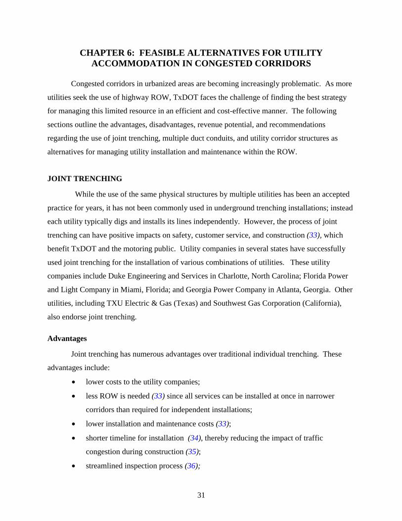
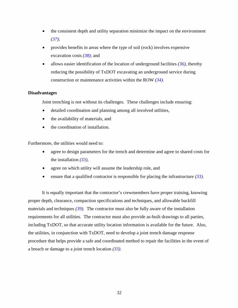
LIST OF FIGURES Page Figure 2-1. English Trench Design (6)........................................................................................... 9 Figure 2-2. Example of Steam Tunnel with Utilities (13)............................................................ 11 Figure 2-3. Steam Tunnel with Utilities (13). .............................................................................. 11 Figure 2-4. Utilidor Vertical Tower (20). .................................................................................... 13 Figure 2-5. Utilidor Outfall (20). ................................................................................................. 13 Figure 2-6. Utilidor Walkway (20). ............................................................................................. 14 Figure 6-1. Joint Trench Installation. . ...................................................................................... 34 Figure 6-2. Joint Trench Schematic ............................................................................................ 34 Figure 6-3. Multiple Duct Conduit Schematics. .......................................................................... 37 Figure 6-4. Case I: Two Examples of Utility Corridor Structures with Walkway
Accessibility. ......................................................................................................................... 42 Figure 6-5. Case II: Smaller Utility Corridor Structure with Limited Accessibility................... 42 Figure 6-6. Shelf and Bracket Support Systems for Utility Corridor Structures. ........................ 42 Figure 6-7. Sample Utility Separations. (6) ................................................................................. 44

xiii
LIST OF TABLES Page Table 6-1. Recommended Utility Accommodation Alternatives................................................. 45 Table 6-2. Advantages and Disadvantages of Utility Accommodation Alternatives. ................. 46 Table 6-3. Design Considerations for Utility Accommodation Alternatives............................... 47

1
CHAPTER 1: INTRODUCTION
BACKGROUND
Public utilities have located transmission lines on federal-aid highway right of way in the
United States (U.S.) since 1916 (1). Individual states control the access and use of right of way
through various laws and regulations that are administered through the states’ departments of
transportation (DOTs). Over the years, as the network of roadways across the U.S. grew and
expanded, so did right-of-way issues. When Congress created the National System of Interstate
and Defense Highways in the mid-1950s, issues regarding access control of right of way
emerged as one of the safety factors of concern. As a result, the American Association of State
Highway and Transportation Officials (AASHTO) developed A Policy on the Accommodation of
Utilities on the National System of Interstate and Defense Highways (2). States were required to
adopt guidelines and regulations that were at least as restrictive as those outlined in the
AASHTO guide. By 1966 these regulations had expanded to include all federal-aid highways
operated by state DOTs (3).
As required by federal mandate, Texas adopted guidelines for accommodating public
utilities in highway right of way. The existing Texas Utilities Accommodation Policy, as
outlined in the Texas Administrative Code (4), outlines the manner in which utilities may install
transmission lines along and across highway right of way. The Texas Utility Code grants this
right to access to the right of way (5). These public utilities include lines that transport natural
gas, water, electricity, telecommunications, cable television, salt water, and common-carrier
petroleum and petroleum-related products. Additionally, privately owned lines are normally
allowed to cross highway right of way.
As deregulation of the utility industry has taken effect, the influx of newly formed
utility companies has resulted in a high demand for access to right of way. New growth and
expansion of underground utilities in urban areas also result in increased demand and increased
competition for the space available on highway right of way for public utilities (6). Concerns
and problems caused by this increased demand require examination of a number of issues. These
issues include congestion, compatibility, associated liability, and the costs attributable to
engineering, construction, maintenance, and relocation of these facilities.
2
One previous method for addressing the issues of compatibility and congestion was
common trenching, which can be traced to Commonwealth Edison and Illinois Bell in 1960 in
the U.S. Such a strategy provides an example of possible solutions to the right-of-way
congestion problem. The study published by the Transportation Research Board emphasizes the
need for appropriate spacing and placement of utilities. This placement ensures compatibility
between the various lines utilizing the trench. Common concerns voiced about the use of
common trenches and utility corridors are the possibility of interference between the electric,
communications, and signal circuits; the corrosion of pipe utilities by stray electrical current; and
the possible cross contamination of water and sewage lines (6).
Williams (3) found a growing need for communication links between major metropolitan
centers and smaller outlying cities. Coincidentally, Interstates and other federal-aid highways
often link these areas. Pressure to abandon the stance by AASHTO and most state regulations to
limit longitudinal occupancy by utilities on the right of way of controlled-access highways with
no frontage roads has grown. This pressure to increase access by public utilities began as far
back as the 1980s and was largely related to the expanding usage of fiber optics in utilities. This
pressure increased as a result of the deregulation of the utility industry and the
Telecommunications Act of 1996.
As new public utilities form, the number of public utilities vying for space within the
state’s right of way increases. However, right of way is a finite resource and is quickly reaching
its capacity, creating congestion and safety problems. Liability and costs attributable to
engineering, construction, and maintenance of these facilities are swiftly rising, creating a
serious problem for primarily the utilities as well as TxDOT. Whether paid by the utility entity
directly or by TxDOT under the State’s Utility Accommodation Policy, these costs are inevitably
borne by the utility rate- and tax-paying citizens of our state.
RESEARCH OBJECTIVE
To address the need to effectively and efficiently manage the limited right-of-way
resource of TxDOT right of way, the TTI team undertook the research to investigate the
feasibility of using a utility corridor structure for utility accommodation within TxDOT rights-of-
way. The objective was to find a solution that (1) provides reasonable access to right of way by
public utilities; (2) allows TxDOT to manage its right of way in a safe and effective manner; and
3
(3) provides a mechanism for TxDOT to recoup some or all of the costs associated with
engineering, constructing, and maintaining utility corridors if appropriate. A utility corridor
structure is one that houses numerous utilities in a small space (cross-section) below ground.
Provisions are made for access, utility separation, drainage, lighting, structural strength, and
other long-term concerns, such as maintenance and security.
METHODOLOGY
The following sections present a detailed description of the approach the research team
used to accomplish the study objectives.
Conduct Literature Review
The research team conducted an extensive literature review to investigate existing
research and practices on the use of utility corridors in publicly owned right of way. This review
included, but was not limited to, previous syntheses published by the National Cooperative
Highway Research Program; information, practices, and lessons learned published by other
states; publications and information referring to the design, use, and maintenance of utility
corridors; documents published by utility corridor equipment manufacturers; and documents
referencing the needs of utility companies for right-of-way space.
Investigate Practices of Other Agencies
The project team conducted an investigation of the practices of other state departments of
transportation regarding the design, construction, leasing, maintenance, legal, and revenue-
generating issues of utility corridors. This investigation consisted of written surveys and
telephone interviews to garner information. The researchers also reviewed utility
accommodation policies from various states and reviewed the plans developed by Parsons,
Brinkerhoff, Quade, and Douglas, Inc. for the installation of a utility corridor within the
Interstate Highway 10 (IH 10) right of way from IH 45 to the Brazos River. The project team
summarized the results to determine if any practices are common across agencies and have
potential in Texas.
4
Assess Interest and Concerns of Stakeholders
TTI assembled a task force of stakeholders to participate in this project. This task force
included members from TxDOT and various public utilities to create a forum for dialogue
between the stakeholders. Periodically, researchers questioned the stakeholder committee via e-
mail to assess their interest in the provision of utility corridors by TxDOT and to determine their
concerns regarding leasing, maintenance, expansion, relocation, and other issues associated with
occupying utility corridors.
Identify Possible Noncompliance Issues in Utility Accommodation Policy
TTI reviewed the Utility Accommodation Policy under the Texas Administrative Code to
determine if any articles within the policy prohibit and deter the use of utility corridors in
TxDOT right of way. The researchers identified potential noncompliance issues and considered
potential solutions to those issues. They also addressed related legislative needs pertaining to the
use of utility corridors by TxDOT.
Evaluate Revenue Potential for Leasing Utility Corridor Space
As part of this task, the project team summarized the review of existing practices to
identify what, if any, revenues are generated by other states with the provision of utility
corridors. The team also evaluated the design, construction, and maintenance costs associated
with utility corridors to determine if TxDOT can either fully or partially recoup the expenses of
providing these corridors to public utilities. The concerns of the stakeholder task force were a
factor in evaluating this potential for generating revenue.
Examine Alternatives for Utility Corridor Congestion
Based on the findings of the previous tasks, the project team developed recommendations
for TxDOT regarding the location of utility corridors in its right of way. These
recommendations include listing of potential solutions to right of way congestion, including joint
trenching, multi-duct conduit, and utility corridor structures. The recommendations also include
draft occupancy agreements between TxDOT and the utility, a discussion on the economic issues
regarding the accommodation strategy, draft specifications and design drawings for utility
corridor structures, and changes required to the Texas statues and the Utility Accommodation
Policy to make the use of utility corridors feasible.

5
Develop Specifications and Design Drawings for Utility Corridors
The team developed draft specifications and design drawings for utility corridor
structures as a potential utility accommodation strategy and considered the placement of various
utilities based on compatibility and to maximize the use of available space.

7
CHAPTER 2: LITERATURE REVIEW
HISTORY OF UTILITY ACCOMMODATION
As stated previously, utilities have located transmission lines on federal-aid highway
ROW since 1916 (1). Individual states control the access and use of right of way through
various laws and regulations that are administered through the state department of transportation
(DOT). The National System of Interstate and Defense Highways was created in the mid-1950s,
and issues regarding access control of rights-of-way as a safety factor surfaced. As a result,
AASHTO developed A Policy on the Accommodation of Utilities on the National System of
Interstate and Defense Highways (2). States were required to adopt guidelines and regulations
that were at least as restrictive as those outlined in the AASHTO guide. By 1966 these
regulations had expanded to all federal-aid highways (3).
Existing Texas laws as outlined in the Texas Administrative Code (4) provide various
utilities the right to install transmission lines along and across highway right of way. These
utilities include lines that transport natural gas, water, electricity, telephone, cable television, salt
water, and common-carrier petroleum and petroleum-related products. Additionally, privately
owned lines are normally allowed to cross highway right of way. These laws form the basis of
the TxDOT Utility Accommodation Policy. This policy, endorsed by the Federal Highway
Administration (FHWA), provides the means for consistent interpretation, application, and
enforcement of right-of-way utility accommodation decisions across the state (7).
GROWING DEMAND FOR UTILITY ACCOMMODATION
As technology and the population grows, the need for expanding existing and adding new
utility lines increases. With the explosion in the telecommunications industry, both public and
private interests are building new networks and upgrading existing networks at an unparalleled
pace (8).
The study by Williams (3) also found a growing need for communication links between
major metropolitan centers and smaller outlying cities. Williams noted that interstates and other
federal-aid highways often link these areas. As a result, pressure to abandon the stance by
AASHTO and most state regulations to limit longitudinal occupancy by utilities on the right of
way of controlled access highways has grown.
8
In 1995 the AASHTO Board of Directors acknowledged the distinctions between fiber-
optic cables and other utilities and revised its stance on longitudinal occupancy by utilities to
except fiber-optic cable lines (8). This policy revision provided the means for formation of
public-private partnerships to “share resources.” This partnership allows each party to tap into or
share the others resources, i.e., the private telecommunications partner gains access to the public
right of way, while the public partner gains access to compensation in the form of
telecommunications facility access, monetary compensation, or a combination of both. The
compensation to the public partner is generally over and above the administrative cost of the
facility use (8).
Just as the demand for utility accommodation has increased, the cost of right-of-way
purchase has also increased in recent years. With the proliferation of utilities in limited space
right of way, the complexity of detecting and relocation of utility lines during transportation
infrastructure projects has become a more complex issue. In order to successfully accommodate
utilities in congested right-of-way conditions, this analysis examined several methods including
trenching, joint trench encased utilities, and utility corridors.
TRENCHING
One method for addressing the issues of compatibility and congestion was common
trenching. Common trenching methods in the United States can be traced to Commonwealth
Edison and Illinois Bell in 1960. In 1968 the Ministry of Public Building and Works in England
began a 2-year comprehensive study of common trenching and devised a design depicted in
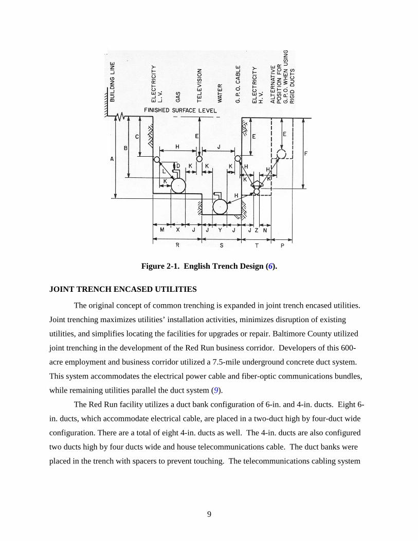
Figure 2-1. This trenching design study emphasizes the need for appropriate spacing and
placement of utilities. The placement utilized in this design ensures compatibility between the
various lines utilizing the trench. One of the common concerns voiced about the use of common
trenches and utility corridors is the possibility of interference between the electric,
communications, and signal circuits; the corrosion of pipe utilities by stray electrical current; and
the possible cross contamination of water and sewage lines (6).
9
Figure 2-1. English Trench Design (6).
JOINT TRENCH ENCASED UTILITIES
The original concept of common trenching is expanded in joint trench encased utilities.
Joint trenching maximizes utilities’ installation activities, minimizes disruption of existing
utilities, and simplifies locating the facilities for upgrades or repair. Baltimore County utilized
joint trenching in the development of the Red Run business corridor. Developers of this 600-
acre employment and business corridor utilized a 7.5-mile underground concrete duct system.
This system accommodates the electrical power cable and fiber-optic communications bundles,
while remaining utilities parallel the duct system (9).
The Red Run facility utilizes a duct bank configuration of 6-in. and 4-in. ducts. Eight 6-
in. ducts, which accommodate electrical cable, are placed in a two-duct high by four-duct wide
configuration. There are a total of eight 4-in. ducts as well. The 4-in. ducts are also configured
two ducts high by four ducts wide and house telecommunications cable. The duct banks were
placed in the trench with spacers to prevent touching. The telecommunications cabling system
10
was placed in the trench on top of the electrical duct bank with a 4-in. separation. The system
was then encased in 3 in. of concrete (9).
UTILITY CORRIDORS
A corridor as defined by Webster’s New Collegiate Dictionary (10) is a passageway into
which compartments or rooms open or a narrow passageway or route. The practice of using such
a structure for utilities is atypical. However, a few examples were found including the use of
pipelines, tunnels, and steam tunnels.
Pipelines as Utility Corridors
The Williams Companies began building pipelines in the early twentieth century and by
the early 1980s had assembled a nationwide system of natural gas pipelines (11). In 1985 the
company created a subsidiary company, Williams Telecommunications Company (WilTel), and
pioneered the idea of using decommissioned pipelines between Kansas City and Des Moines and
Omaha and Chicago as conduit for fiber-optic cables. The result of the very successful
experiment was an 11,000-mile digital network, which encouraged long-distance competition. In
1990 WilTel began carrying live video over the fiber-optic network. Today, Williams
Communications Group has over 40,000 miles of network and broadband network architecture
and is the largest independent source for video, data, and voice communications (12).
Tunnels and Steam Tunnels as Utility Corridors
Most universities, colleges, and large institutional campuses have a network of steam
tunnels or utility tunnels. These tunnels carry high-pressure steam pipes and other utility lines,
including water and sewer. Institutions often use steam lines and chilled water lines to heat and
cool buildings. Institutions also often run data, telecommunication, and fiber-optic cabling
through the tunnel system. Finding information on the tunnels is limited because of the large
number of students who find exploring the off-limits tunnels an exciting adventure. However,
information on the extent and types of tunnels can be acquired from Internet sources. The
website by the Urban Explorers network (13) is an example of this type of information. The site
provides information on numerous tunnels through documents, logs, photographs, and maps all
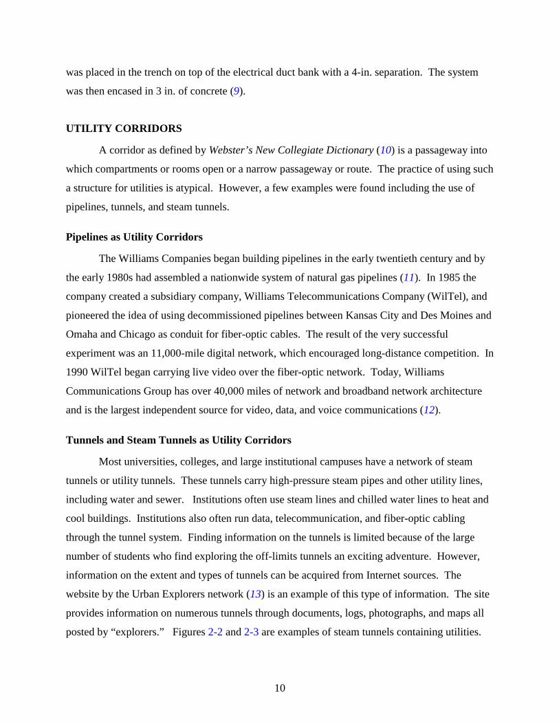
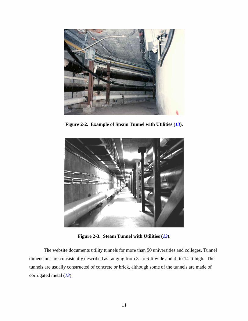
posted by “explorers.” Figures 2-2 and 2-3 are examples of steam tunnels containing utilities.
11
Figure 2-2. Example of Steam Tunnel with Utilities (13).
Figure 2-3. Steam Tunnel with Utilities (13).
The website documents utility tunnels for more than 50 universities and colleges. Tunnel
dimensions are consistently described as ranging from 3- to 6-ft wide and 4- to 14-ft high. The
tunnels are usually constructed of concrete or brick, although some of the tunnels are made of
corrugated metal (13).
12
Utilidors
Cold-climate communities struggle each winter to keep water and water-based effluent
from freezing. An expensive but effective way to solve all these challenges is for the community
to build a utilidor. This heated tunnel can house all utilities (electrical, gas, and water), thereby
making them easily accessible for installation and maintenance. If sufficient in size, it can also
serve as a pedestrian passageway between buildings (14). The underground tunnel is a
prefabricated system often made of corrugated metal and insulated for cold-weather climates
(15). However some utilidors are aboveground — especially in northern locations where there is
nothing but solid rock — and may be constructed of concrete, brick, or wood. Utilidors are
found in Barrows, Alaska; Nome, Alaska; Fort McPherson, Alaska; Norman Wells in the
Northwest Territory, Canada; University of Alaska at Fairbanks; McMurdo field station in
Antarctica; and Walt Disney World (16, 17).
There are 5 miles of utilidor tunneling used at the University of Alaska at Fairbanks
(UAF). The UAF utilidors are concrete enclosures that range 1 to 3 ft in width and 4 to 6 ft in
height and contain steam pipes and electric utilities. Utilidors have been used on the UAF
campus since 1938 (17).
Walt Disney World has an extensive utilidor system that consists of a 9-acre underground
network. The underground system consists of 15-ft walkways, meeting rooms, costume storage
rooms, computer rooms, cafeterias, break rooms, maintenance facilities, and utilities. The
utilities include a vacuum trash system (AVAC) system for garbage. Garbage is picked up in the
park and dumped into AVAC portals. It is then sucked to a central processing facility using
compressed air (18).
The utilidors occupy 392,040 square feet of space. They provide hidden access for Walt
Disney World characters as they travel from one location to another, security for cash delivery,
and storage for emergency provisions. Although the Epcot Center does not have an extensive
tunnel system, it has small tunnels connecting Innoventions and The Land, as well as Universe of
Energy, Spaceship Earth, and the Living Seas. The Epcot tunnels include rooms for storage,
kitchens, and meeting and break rooms (18).
Utilidors are also used in Antarctica. The utilidor was first designed and constructed for
the Antarctica field stations by the U.S. Navy. McMurdo Station — the largest Antarctic station
— was constructed in 1955 to support Antarctic operations and is located on Ross Island. The
13
station has 85 buildings and houses 1250 personnel. The monthly mean temperatures range from
27o F in January to –18o F in August. The utilidor is 50 ft below the surface and has an ambient
temperature of –50o F (19).
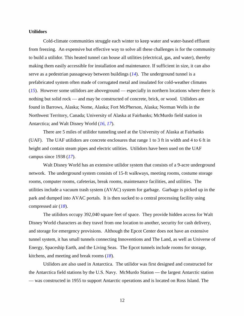
McMurdo station is currently in the process of being rebuilt and will include new
utilidors. Members of the South Pole team have graciously provided the following pictures of
the new utilidor. Figure 2-4 depicts the connector link between the underground industrial
components — fuel storage, fuel distribution, vehicle maintenance, shops, power plant, and
potable water facility — and the aboveground portion of the new station (20).
Figure 2-4. Utilidor Vertical Tower (20).
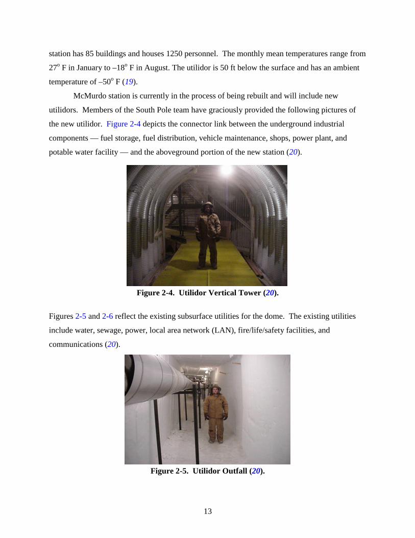
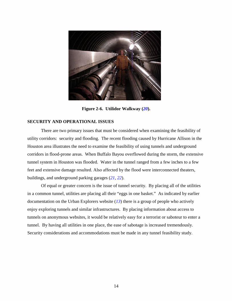
Figures 2-5 and 2-6 reflect the existing subsurface utilities for the dome. The existing utilities
include water, sewage, power, local area network (LAN), fire/life/safety facilities, and
communications (20).
Figure 2-5. Utilidor Outfall (20).
14
Figure 2-6. Utilidor Walkway (20).
SECURITY AND OPERATIONAL ISSUES
There are two primary issues that must be considered when examining the feasibility of
utility corridors: security and flooding. The recent flooding caused by Hurricane Allison in the
Houston area illustrates the need to examine the feasibility of using tunnels and underground
corridors in flood-prone areas. When Buffalo Bayou overflowed during the storm, the extensive
tunnel system in Houston was flooded. Water in the tunnel ranged from a few inches to a few
feet and extensive damage resulted. Also affected by the flood were interconnected theaters,
buildings, and underground parking garages (21, 22).
Of equal or greater concern is the issue of tunnel security. By placing all of the utilities
in a common tunnel, utilities are placing all their “eggs in one basket.” As indicated by earlier
documentation on the Urban Explorers website (13) there is a group of people who actively
enjoy exploring tunnels and similar infrastructures. By placing information about access to
tunnels on anonymous websites, it would be relatively easy for a terrorist or saboteur to enter a
tunnel. By having all utilities in one place, the ease of sabotage is increased tremendously.
Security considerations and accommodations must be made in any tunnel feasibility study.
15
CHAPTER 3: PRACTICES OF OTHER AGENCIES
The project team conducted an investigation of the practices of other state departments of
transportation regarding the design, construction, leasing, maintenance, legal, and revenue-
generating issues of utility corridors. The intent was to determine if other states have used utility
corridors, what their experience has been regarding these structures, and the utility
accommodation and relocation policy for their state.
PERSONAL INTERVIEWS
This investigation consisted of researchers conducting personal telephone interviews to
garner information on what other states and agencies are doing with respect to utility corridors
and especially permanent structures for the joint location of numerous utilities along the highway
ROW. Researchers interviewed representatives from 39 states in this task. Each interview lasted
approximately 30 minutes, and researchers assured respondents that participation was entirely
voluntary. Appendix A contains a copy of the interview instrument researchers used to complete
this task.
DEFINITIONS
The interviewers initially provided the interviewees with several definitions to clarify the
subject of the study. These definitions were as follows:
• Utility corridor: an area of highway right of way designated or used for the joint
location of utilities, either public or private;
• Utility corridor structure: a joint-use facility or conduit constructed or installed
within a highway right of way that can accommodate a variety of utilities, either
public or private, to minimize congestion of utilities within the ROW and to facilitate
co-location, maintenance, and access to utilities (other terms may include utility
closet, duct bank, utility tunnel, etc.); and
• Utility corridor policy: an organizational policy that encourages or mandates the use
of utility corridor structures in areas with congestion ROW (most likely contained
within an organization’s Utility Accommodation Policy, Utility Relocation Policy, or
similar policy governing the relocation of public utilities for transportation projects).
16
PRACTICES OF OTHER AGENCIES
The following sections provide a summary of the practices of other state agencies
regarding utility corridors and utility corridor structures. Appendix B contains the detailed
responses of interviewees for each question.
Presence of Utility Corridor Structures
Researchers asked respondents if their state utilizes a utility corridor structure to
accommodate various types of utilities within the ROW. Of the 39 states responding, six (15
percent) indicated some utilization of a common structure for utilities, most often in special
situations or for transverse installation across a transportation facility, such as under a bridge
deck. Other states indicated that they use joint trenching but no single enclosed structure for
utilities. It is important to note that one responding state, Connecticut, does not allow utilities
within the ROW of interstates or highways. Other common names for a utility corridor structure
include the following: utility corridor gallery, conduit, utility tray, trench, duct system, utilidor,
and utility support structure.
Utility Corridor Policy
State practices regarding utility corridor policies or accommodation policies that govern
the usage of utility corridor structures vary. Thirteen states (33 percent) participating in the
study indicated that they have a utility corridor policy in place to some degree. However, states
exhibit a wide disparity in how they implement such a policy, from a stand-alone document to
inclusion within their accommodation policy to review and approval on a case-by-case basis.
For those states responding, utilization of a utility accommodation policy began in some states as
early as the 1950s, while others did not implement such policies until as late as 1992. Some
states also have a periodic review process to ensure that the policy remains current. Fourteen of
the participating states (39 percent) provided researchers with their current policy for review.
Seven participating states (18 percent) are currently developing a utility accommodation
policy, most as a result of the increase in telecommunications needs. Of those states (8–21
percent of respondents) that do not have a formal policy regulating utility access within the
ROW, some either do not regulate access at all and others only have a simple permitting process
to track utility location. In Oregon, as in other states, state law allows utilities to be in the ROW
but highway dollars can only be used for the good of the highway users. Thus, the DOT cannot
17
expend funds to purchase additional ROW to accommodate the utilities; the utilities must locate
within the typical ROW purchased for highways. Hence, crowded ROW is commonplace.
Twenty-three of the thirty-nine respondents (59 percent) expressed satisfaction with their
current policy or method for utility accommodation. An interesting fact is that a substantial
percentage of respondents indicated satisfaction with their current method even though that
method does not involve a formal policy. Respondents believed that several aspects of their
policy or method were most helpful in terms of controlling access in the ROW, including having
a written policy that has a common set of rules, consistency of application, requiring interagency
communication, having a formal permit procedure, and having the power to dictate where
utilities can locate. Opinions regarding unsatisfactory aspects of their agency’s policy include
being unable to control the number of utilities within the ROW, lacking underground
accommodation standards, time required for inspections of installation, and difficulty in
enforcing some rules, such as traffic control and fill requirements.
When asked about the usefulness of a state’s current utility corridor policy, most
interviewees from states with policies felt that at a minimum, their policy has been useful in
mitigating utility congestion. Some of these respondents further elaborated on ways in which
their policy has been helpful. Common responses included that the policy enables their agency
to improve safety, ensure consistent application across the state, control what utility can be in the
ROW, and conserve valuable ROW space. Interestingly, four respondents stated that their policy
has not been useful with respect to controlling the number of telecommunications companies in
the ROW.
Researchers asked the interviewees to identify suggestions for improving their agency’s
existing policy to improve their ability to mitigate utility congestion. Sixteen of the 39
respondents (41 percent) indicated a number of changes, including requiring greater use of
subsurface utility engineering (SUE) in the design phase, restricting the number of facilities any
one company can place and disallow abandonment, allowing fewer utilities in the ROW and the
right to deny utility companies access, and being able to specifically designate where each type
of utility can be placed. SUE is the nondestructive process of accurately locating, identifying,
and mapping underground utilities and is an interdisciplinary service involving professional
engineers, geologists, and licensed land surveyors (23).
18
When asked what utilities are typically accommodated within a state’s ROW and design
process, 28 respondents (72 percent) offered clarification as to what utilities are accommodated,
which run the gamut of public and private utilities, including:
• electricity,
• gas,
• telephone,
• fiber,
• cable television
• liquid petroleum,
• water,
• sanitary sewer,
• natural gas,
• steam, and
• telegraph.
However, it is important to note that the combination of utilities allowed in the ROW varies from
state to state, with some allowing all utilities and a select few allowing no utilities within the
ROW. Only 10 of the 39 respondents (25 percent) indicated that all of the utilities typically
accommodated within their ROW are covered by their utility corridor policy. One reason for a
state not addressing all utilities within their policy is that the utility has direct experience with
installation and knows the best way to address this issue.
Utility Corridor Structure
The following sections briefly summarize the state practices regarding utility corridor
structures.
Design
None of the respondents indicated that their state has a preferred or typical standard
design for a utility corridor structure. However, one respondent did indicate that they have an
experimental design. Other states use designs that appear to be more oriented toward a
transverse application crossing a freeway rather than a longitudinal design. Even though no
states have designs that reflect the ultimate capacities for various types of utilities, some
19
commented that utility companies generally determine the capacity of their facilities to
accommodate future service. Moreover, no respondent had an approved structure from a
manufacturer for the agency or utility policy.
Two of the respondents were able to identify the parameters that were considered in the
design of any utility corridor structure. While it is difficult to draw any clear conclusions from
this response rate, indications are that physical items such as capacity, durability, and access play
a more important role in the design than other parameters, such as the utility that is in the
structure or even cost.
Four respondents indicated what utilities are allowed inside their structure, at such times
when these agencies use them. Those allowed are water, wastewater, gas, electricity, telephone,
and cable. However, water and wastewater are also disallowed in some cases. Researchers also
asked respondents to indicate the types of concerns they have regarding utility placement and
segregation within a utility corridor structure. Two respondents answered this question, with
power, susceptibility, monitoring capability, communication needs, and access needs being of
medium concern, while monitoring capabilities, standards for clearance, and a minimum depth of
36 in. to 48 in. being of high concern.
Construction
Two respondents indicated that they use a prefabricated utility corridor structure rather
than building one on site. In one case, a design manual dictates the procedure for installing the
prefabricated structure, whereas the prefabricated structure is still a concept in the other case and
has yet to be used. Also, one state has a typical or standard construction methodology or
procedure for building utility corridor structures on site. With respect to determining the cost of
a utility corridor structure, two agencies used a bid procedure (low or competitive), while a third
used a reimbursement process for the utilities to refund the state’s up-front costs for building the
structure.
Leasing
Only one respondent indicated that their state has occupancy/leasing agreements with the
utilities that share the utility corridor. However, this response was for occupying the corridor
and not a structure. In this case, the agreements address the issuance of permits and not the true
20
leasing of the ROW. One respondent indicated that these agreements are standard across all
utilities, while another noted that the agreements vary by utility.
Maintenance
Five of the 39 respondents (12.8 percent) indicated that each utility maintains its portion
of the corridor and utility corridor structures. No respondent indicated that one entity has the
overall responsibility for the maintenance of the corridor, indicating that a shared responsibility
is the principle under which current agreements operate. One respondent, however, indicated a
willingness to explore the concept of one agency having the overall responsibility for
maintenance of the corridor and structures. Most states have no procedure for alerting other
utilities of maintenance issues that may affect their services. However, some states have a
situation where shared facility contracts create a shared liability. In such cases, letters of
agreement cover procedures regarding access, maintenance, and use.
Legal
Five of the 39 respondents (12.8 percent) remarked on the issue of legal barriers that they
had to overcome before they could use their utility corridor policy. One comment was that they
only had to overcome political barriers to use utility corridor structures. Other states indicated
that they had no problems as long as the utility corridor structure was used for highways or
utility construction (e.g., wastewater or water to rest areas) or as long as the structure was
integrated into the available highway ROW. Also, one state remarked that current shared facility
contracts sufficed for such a structure.
Cost
When asked how their state funds utility corridor structures, two states responded. In no
case did they use a separate funding pool. Rather, they used a combination of highway
construction funds and utility funds to pay for utility relocation or the structure.
Revenue
Four respondents identified items with regard to the issue of generating revenue and its
role in a utility corridor policy. For example, in Iowa, any revenues generated from a utility
21
corridor structure goes to a beautification fund. Another state has agreements with the utilities in
which the utilities pay for the structure.
General Comments
At the end of the interview, each respondent had the opportunity to make additional
comments regarding the subject of utility corridor structures. In general, most were interested in
the project and, while many do not use utility corridor structures, they are eager to learn what
other states are doing and their success rate in this arena. In total, 33 of the 39 respondents (85
percent) expressed an interest in receiving a copy of the survey results, indicating a high degree
of interest in this project across the nation, as many states are asking some of these same
questions.

23
CHAPTER 4: ASSESS INTEREST AND CONCERNS OF STAKEHOLDERS
TTI assembled a task force of stakeholders to participate in this project. This task force
included members from TxDOT and various public utilities to create a forum for dialogue
between the stakeholders. Periodically, researchers questioned the stakeholder committee via e-
mail to assess their interest in the provision of utility corridors by TxDOT and to determine their
concerns regarding leasing, maintenance, expansion, relocation, and other issues associated with
occupying utility corridors. The following sections provide a brief summary of the results of this
assessment. Appendix C contains a complete list of the questions researchers asked of this
group, while Appendix D contains the detailed responses of the task force for each question.
Although the response rates were not as high as the research team would have preferred, those
members that did respond to the posed questions provided valuable insight into the concerns of
the utilities in regard to utility structures.
TYPICAL UTILITY INSTALLATION
Researchers initially asked the task force to provide basic information regarding their
typical utility installation within TxDOT ROW. These questions established a basis for
comparing the installation of a utility structure for longitudinal use in place of individual utility
installations.
Cost of Installation
Researchers asked the task force for their typical linear foot costs to build and install a
buried conduit within the ROW to encase their utility line. The task force was to provide costs
both with and without the purchase of ROW. One task force member responded that the typical
costs vary from $40 to $100 per linear foot, depending on the terrain. The cost of ROW adds $2
per linear foot to this price. Based on current costs for similar installations on projects within
TxDOT ROW, these costs are on par with typical industry costs (24).
Use of Duct Banks or Multiple Casings
When asked if they currently use or have used in the past multiple casings or multi-duct
conduit within the ROW, one respondent answered that they use both multiple casings and/or
24
multiple direct buried lines. All of the conduit systems currently installed by this utility have
multiple ducts.
UTILITY CORRIDOR STRUCTURE
The following sections address the task force responses to questions regarding utility
corridor structures and their potential use within TxDOT ROW.
Willingness to Participate
The researchers asked the task force to consider four scenarios in which their utility
might potentially participate in a utility corridor structure. They stressed that the circumstances
under which TxDOT would use such a facility would be fairly limited. The intent was to assess
the viability of a utility company or consortia of utility companies, rather than TxDOT, providing
a utility structure for use within the TxDOT ROW. The four scenarios included two in which
participation by the utility would be optional and two in which participation would be
mandatory. Each pair of scenarios involved the likelihood of revenue potential or lack thereof
for the company(ies) installing the structure.
In general, the utilities were not particularly interested in the utility structure concept in
any scenario, citing the possibility of the structure effectively prohibiting or limiting access to
the ROW by utilities, thereby limiting competition. Other concerns included the substantial
capital resources necessary for a utility or consortia to construct the structure with the possibility
of no revenue potential and the uncertain future market for such facilities. Furthermore, they
mentioned other concerns, such as security, access, liability, and maintenance that TxDOT would
need to address before they would be willing to locate within a structure.
Spacing and Location Requirements
Researchers asked the task force to comment on any specific spacing or location
requirements they might have that would govern the placement of various types of utilities
within an enclosed structure. The TxDOT representative responded that current spacing
requirements for utilities within TxDOT ROW are governed by Chapter 43 of the Texas
Administrative Code (4). Often referred to as the Utility Accommodation Policy (UAP), this
document is based on national standards for safety for both the utilities and the highway facility
in which ROW they reside. However, these requirements are not necessarily exhaustive and may
25
not address all of the spacing requirements or preferences from the perspective of individual
utilities. One utility responded that they require a 12-in. dirt separation of electric and
telecommunication lines in an open trench and conduit run. Furthermore, they would not locate
a telecommunication facility in the same structure as a natural gas pipeline.
Inspection and Maintenance
No task force members responded to the question regarding inspection and maintenance
procedures and frequency thereof that they would undertake to ensure the safety and
functionality of a utility corridor structure.
Design of Structure
One of the more critical components of a utility corridor structure is its design. The
research team attempted to glean from the task force those design issues they felt were critical
for their inclusion. Such issues might include lighting, ventilation, drainage, line identification,
etc. When asked about these issues, no members responded regarding any standards they might
use for these facilities. However, when asked what their specifications were when installing a
line beneath a railroad, two task force members responded. Typically, a utility submits a permit
to the appropriate railroad office for approval, but requirements for installation vary. As a rule,
they normally install at least 5 ft below ditch grade with a bore and place steel casing under the
track. Arial crossings usually require anywhere from 22 ft to 27 ft of clearance.
Access Needs
As noted in the concerns of the stakeholders regarding their willingness to participate in a
utility structure, access to the facility is of importance to the utilities. Thus, the research team
asked the task force a number of questions regarding their need to access their lines and what
that access would entail. When asked how frequently they would require access along the
longitudinal length of a utility corridor structure, one utility responded that on large cable runs
they would require access every 500 ft to 750 ft. The maximum distance between access points
would be 2000 ft because they are required to bond and ground their lines at that spacing.
Furthermore, vertical access via manholes would be sufficient for these access points. Larger
access for equipment or the movement of materials for repair or maintenance of their utility
would be needed, but the utilities noted no specific frequency of access points for this purpose.
26
Abandonment
Finally, the research team asked the task force whether the constrained space within a
utility structure would impact their typical abandonment procedures as they relate to traditionally
buried conduit. One respondent noted that their typical process is to have rights to two conduits
minimum, one for use and one to serve as a spare. Their typical procedure is that if existing
facilities are exhausted or need replacing or repair, the utility places appropriate-sized new
facilities in the vacant conduit, which would allow the existing facilities to be removed from the
other conduit so that the company would once again have a spare conduit. In short, they
typically never truly abandon a line within the ROW.
27
CHAPTER 5: NONCOMPLIANCE ISSUES IN TEXAS STATUTES AND UTILITY ACCOMMODATION POLICY
A key component to making the use of a utility corridor structure feasible in Texas is
statutory and policy support of such an effort. Thus, as part of the research project, the research
team reviewed the Texas statutes and the Utility Accommodation Policy under the Texas
Administrative Code to determine if any articles within the policy prohibit and deter the use of
utility corridors in TxDOT right of way. The following sections outline potential noncompliance
issues for both of these legal documents and propose potential solutions to those issues.
TEXAS STATUTES
One of the key issues surrounding the potential need for longitudinal utility corridor
structures is the limited space within the ROW into which utilities must locate. As more utilities
request permits for access, particularly in congested urbanized areas, the ROW becomes
congested as well. This congestion can create problems when TxDOT must undertake
maintenance or reconstruction projects by delaying construction while utilities relocate or by
restricting activities within the ROW to prevent damage to existing lines. One potential benefit
of a utility corridor structure is the co-location of utilities within one structure, the location and
size of which is thoroughly documented, thereby reducing the likelihood of damage during
construction or maintenance activities within the ROW. Also, locating utilities within one
structure can reduce construction delays.
ROW Purchasing Authority
One statutory obstacle to the use of longitudinal utility corridor structures is the inability
of TxDOT to purchase ROW for anything other than transportation purposes. Currently,
TxDOT, through action of the Texas Transportation Commission, may purchase property as
outlined in Subchapter D, Section 203.051, of the Texas Transportation Code (25); Section
203.052 (26) outlines the specific purpose for which that property can be used. Furthermore, the
TxDOT Roadway Design Manual governs the ROW needs for any transportation project based
on a safe and appropriate design (27). In short, TxDOT cannot purchase ROW for the express
purpose of accommodating utilities. The utilities must locate within the ROW acquired for the
transportation project.
28
A problem arises with this restriction on ROW acquisition regarding utility corridor
structures. For example, it is highly likely that in some congested urbanized areas where TxDOT
might consider the use of a utility structure, the typical ROW for a project will not accommodate
the structure. Under the current statutes, TxDOT could not use a utility structure in such a
location. Therefore, to enable TxDOT to have the freedom to consider a utility corridor structure
when deemed appropriate, the Texas statutes may need to grant TxDOT appropriate authority to
acquire ROW for the express purpose of installing utility corridor structures in congested
urbanized areas where they can benefit TxDOT and the needs of the citizens of Texas. Thus, the
research team recommends appropriate additions to the Texas statutes to reflect that authority, as
suggested in the draft sample legislation provided on page 95 in Appendix E.
Utility Corridor Structure Leasing Authority
In the event that TxDOT decides to install a utility corridor structure within the highway
ROW, TxDOT may wish to lease the space to utilities rather than simply granting them access,
as is the current practice. Since the inclusion of a utility corridor structure on a highway project
is not a typical utility accommodation, typical utility accommodation procedures might not be
appropriate. In such cases, leasing the space could assist in offsetting the construction costs
associated with installing the structure or ongoing maintenance costs necessary to ensure the
continued operation and security of the utility lines.
A second statutory limitation to utility corridor structure use lies in TxDOT’s leasing
authority. Current Texas statutes allow TxDOT to lease part of a right of way if it will not be
needed for a highway purpose during the term of the lease (28), which includes leasing the asset
to a public utility provider. However, in the case of a utility corridor structure, the asset (i.e., the
ROW occupied by the structure) would be in use during the term of the lease. Thus, specific
statutory authority to lease the corridor structure is required. The sample legislation to enable
this authority is provided on page 96 in Appendix E. However, TxDOT needs to ensure that
receiving income from the lease of a utility corridor structure is not considered a nonessential
governmental function, thereby making that income subject to federal tax laws, as outlined in
Section 115 of the U.S. Internal Revenue Code (29). The structure of the utility corridor
structure project and subsequent leases and the classification of revenues from those leases can
subject TxDOT to federal income tax liability (30).
29
UTILITY ACCOMMODATION POLICY
The existing Texas Utilities Accommodation Policy, as outlined in the Texas
Administrative Code (31), outlines the manner in which utilities may install transmission lines
along and across highway right of way. After assessing the current requirements in the policy,
the research team developed a number of recommended changes that are necessary to facilitate
the efficient management of TxDOT ROW using joint trenching, multi-duct conduit, and utility
corridor structures. The following sections briefly discuss the recommended changes located in
Appendix F.
Definitions
The policy currently does not specifically define the three accommodation strategies
discussed in this research: joint trenching, multi-duct conduit, and utility corridor structure.
Thus, the research team recommends adding definitions for these terms to the preexisting list
included in §21.31. The draft recommended wording for these definitions is provided on page
99 of Appendix F.
References
Once defined, the terms joint trenching, multi-duct conduit, and utility corridor structure
become appropriate for mention within the policy. Thus, the research team identified numerous
places in the current policy where reference to one or more of these terms is warranted. For
example, the addition of a general reference to utility corridor structures is needed in §21.37, as
outlined on page 99 of Appendix F. Furthermore, the research team drafted several new sections
recommending the use of joint trenching, multi-duct conduit, and utility corridor structures
where appropriate. The draft wording for these new subsections in §21.38 are shown on page 99
of Appendix F.
The policy currently has sections devoted to the installation of different types of utilities
within TxDOT ROW. However, since utility corridor structures for longitudinal purposes are
not currently included in the policy, none of these sections make reference to such structures.
Thus, the research team drafted sample changes to these sections (§21.42, §21.43, §21.44,
§21.45, §21.46, §21.50, and §21.51) that are provided on pages 99-100 of Appendix F. Finally,
the research team also added references to utility corridor structures in those sections covering
30
occupancy agreement forms and notice forms (§21.52, §21.53, and §21.54) as noted on page 100
of Appendix F.
Utility Corridor Structure Rule
The Utility Accommodation Policy currently contains a section that covers the use of
utility structures for the transverse accommodation of utilities (32). However, the policy does
not address the use of such structures for longitudinal use. Thus, the research team recommends
adding a section regarding this use of structures to the said rule, as provided on page 100 of
Appendix F. This rule addresses the various requirements necessary to effectively and safely use
a utility corridor structure for longitudinal accommodation, similar in nature to the rule
governing transverse use of such a structure.
31
CHAPTER 6: FEASIBLE ALTERNATIVES FOR UTILITY ACCOMMODATION IN CONGESTED CORRIDORS
Congested corridors in urbanized areas are becoming increasingly problematic. As more
utilities seek the use of highway ROW, TxDOT faces the challenge of finding the best strategy
for managing this limited resource in an efficient and cost-effective manner. The following
sections outline the advantages, disadvantages, revenue potential, and recommendations
regarding the use of joint trenching, multiple duct conduits, and utility corridor structures as
alternatives for managing utility installation and maintenance within the ROW.
JOINT TRENCHING
While the use of the same physical structures by multiple utilities has been an accepted
practice for years, it has not been commonly used in underground trenching installations; instead
each utility typically digs and installs its lines independently. However, the process of joint
trenching can have positive impacts on safety, customer service, and construction (33), which
benefit TxDOT and the motoring public. Utility companies in several states have successfully
used joint trenching for the installation of various combinations of utilities. These utility
companies include Duke Engineering and Services in Charlotte, North Carolina; Florida Power
and Light Company in Miami, Florida; and Georgia Power Company in Atlanta, Georgia. Other
utilities, including TXU Electric & Gas (Texas) and Southwest Gas Corporation (California),
also endorse joint trenching.
Advantages
Joint trenching has numerous advantages over traditional individual trenching. These
advantages include:
• lower costs to the utility companies;
• less ROW is needed (33) since all services can be installed at once in narrower
corridors than required for independent installations;
• lower installation and maintenance costs (33);
• shorter timeline for installation (34), thereby reducing the impact of traffic
congestion during construction (35);
• streamlined inspection process (36);
32
• the consistent depth and utility separation minimize the impact on the environment
(37);
• provides benefits in areas where the type of soil (rock) involves expensive
excavation costs (38); and
• allows easier identification of the location of underground facilities (36), thereby
reducing the possibility of TxDOT excavating an underground service during
construction or maintenance activities within the ROW (34).
Disadvantages
Joint trenching is not without its challenges. These challenges include ensuring:
• detailed coordination and planning among all involved utilities,
• the availability of materials, and
• the coordination of installation.
Furthermore, the utilities would need to:
• agree to design parameters for the trench and determine and agree to shared costs for
the installation (33),
• agree on which utility will assume the leadership role, and
• ensure that a qualified contractor is responsible for placing the infrastructure (33).
It is equally important that the contractor’s crewmembers have proper training, knowing
proper depth, clearance, compaction specifications and techniques, and allowable backfill
materials and techniques (39). The contractor must also be fully aware of the installation
requirements for all utilities. The contractor must also provide as-built drawings to all parties,
including TxDOT, so that accurate utility location information is available for the future. Also,
the utilities, in conjunction with TxDOT, need to develop a joint trench damage response
procedure that helps provide a safe and coordinated method to repair the facilities in the event of
a breach or damage to a joint trench location (33).
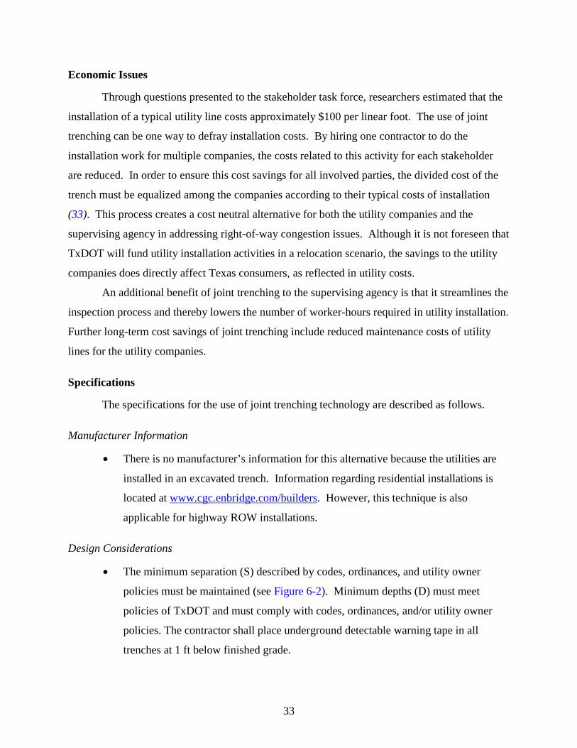
33
Economic Issues
Through questions presented to the stakeholder task force, researchers estimated that the
installation of a typical utility line costs approximately $100 per linear foot. The use of joint
trenching can be one way to defray installation costs. By hiring one contractor to do the
installation work for multiple companies, the costs related to this activity for each stakeholder
are reduced. In order to ensure this cost savings for all involved parties, the divided cost of the
trench must be equalized among the companies according to their typical costs of installation
(33). This process creates a cost neutral alternative for both the utility companies and the
supervising agency in addressing right-of-way congestion issues. Although it is not foreseen that
TxDOT will fund utility installation activities in a relocation scenario, the savings to the utility
companies does directly affect Texas consumers, as reflected in utility costs.
An additional benefit of joint trenching to the supervising agency is that it streamlines the
inspection process and thereby lowers the number of worker-hours required in utility installation.
Further long-term cost savings of joint trenching include reduced maintenance costs of utility
lines for the utility companies.
Specifications
The specifications for the use of joint trenching technology are described as follows.
Manufacturer Information
• There is no manufacturer’s information for this alternative because the utilities are
installed in an excavated trench. Information regarding residential installations is
located at www.cgc.enbridge.com/builders. However, this technique is also
applicable for highway ROW installations.
Design Considerations
• The minimum separation (S) described by codes, ordinances, and utility owner
policies must be maintained (see Figure 6-2). Minimum depths (D) must meet
policies of TxDOT and must comply with codes, ordinances, and/or utility owner
policies. The contractor shall place underground detectable warning tape in all
trenches at 1 ft below finished grade.
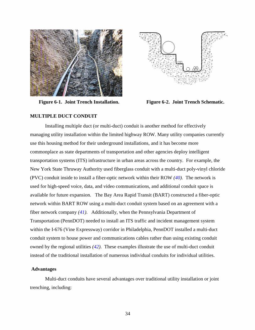
34
Figure 6-1. Joint Trench Installation. Figure 6-2. Joint Trench Schematic.
MULTIPLE DUCT CONDUIT
Installing multiple duct (or multi-duct) conduit is another method for effectively
managing utility installation within the limited highway ROW. Many utility companies currently
use this housing method for their underground installations, and it has become more
commonplace as state departments of transportation and other agencies deploy intelligent
transportation systems (ITS) infrastructure in urban areas across the country. For example, the
New York State Thruway Authority used fiberglass conduit with a multi-duct poly-vinyl chloride
(PVC) conduit inside to install a fiber-optic network within their ROW (40). The network is
used for high-speed voice, data, and video communications, and additional conduit space is
available for future expansion. The Bay Area Rapid Transit (BART) constructed a fiber-optic
network within BART ROW using a multi-duct conduit system based on an agreement with a
fiber network company (41). Additionally, when the Pennsylvania Department of
Transportation (PennDOT) needed to install an ITS traffic and incident management system
within the I-676 (Vine Expressway) corridor in Philadelphia, PennDOT installed a multi-duct
conduit system to house power and communications cables rather than using existing conduit
owned by the regional utilities (42). These examples illustrate the use of multi-duct conduit
instead of the traditional installation of numerous individual conduits for individual utilities.
Advantages
Multi-duct conduits have several advantages over traditional utility installation or joint
trenching, including:
35
• multi-duct conduits can accommodate multiple utilities in one conduit, thereby
requiring less space within the ROW;
• lines for individual utility companies are simply installed in separate compartments
within one conduit, reducing the overall cost of multiple installations (42, 43);
• multi-duct conduits can be a solution to maximizing the use of the ROW without
adversely impacting the highway environment or the motoring public in urbanized
areas with limited ROW and numerous utilities requiring access;
• the conduit can be installed using trenchless boring or horizontal directional drilling,
which is beneficial in areas with bans against surface trenching for environmental
reasons (44) or when a DOT wishes to minimize the impact of installation on
highway operations; and
• many utility companies currently use multi-duct conduit for underground
installation, thereby increasing the likelihood that utilities will look favorably on this
strategy for utility accommodation.
Disadvantages
Multi-duct conduit for multiple utility accommodation also has some disadvantages.
• The conduit needs to be of adequate size to accommodate future expansion of
existing lines and the housing of additional new utilities in the future. If the utilities
and TxDOT underestimate future needs, the installed conduit will be inadequate and
require the installation of another conduit. This would increase the cost of the utility
accommodation for both parties. However, if the installed conduit has excess
capacity that is not utilized, the utilities may have expended unnecessary costs for
the initial installation. Thus, careful planning and estimates are necessary to ensure
a cost-effective solution.
• Multi-duct conduits are only feasible for compatible utilities. Telecommunications,
power, cable, and similar utilities are compatible and can be co-located within a
multi-duct conduit as long as appropriate federal and other applicable codes are met
regarding casing, separation, and other location requirements. However, these
utilities are not inherently compatible with others, such as water, sewer, natural gas,
36
and petroleum. Therefore, multi-duct conduits cannot be used for all combinations
of utilities.
• Coordination among the participating utilities is important to success. The utilities
must agree upon which inner duct(s) their lines will occupy, and they must develop a
joint trench damage response procedure that helps provide a safe and coordinated
method to repair the facilities in the event of a breach or damage to a joint trench
location (33).
Economic Issues
The installation costs of utility lines in multi-duct conduit systems will be compared to
the cost of traditional single-utility installations which were estimated to be $100 per linear foot.
Utilizing past bid prices for the installation of multi-duct conduit, researchers estimated that the
cost for a bored multi-duct conduit system would be $145 per linear foot. Although at first
glance this appears to be an increase in installation costs, one must remember that this cost is
going to be shared among the participating utilities that will be co-locating their lines in this
structure. Through the use of a single installation that accommodates multiple utility lines, the
costs would be divided appropriately according to the space usage of each company within the
conduit. This division of costs creates a lowered installation cost per utility company and
therefore creates a cost neutral alternative for utility installation in the ROW.
One financial issue that must be carefully examined prior to using a multi-duct conduit
system is the number of compatible utilities that will need accommodation as well as expected
growth of demand in the future. Because of the costs of the installation, excess capacity can
create unnecessary higher installation costs. However, if the installation does not meet the
demand then there could be a need to go in and place a second conduit to meet the utility needs.
This would once again create unnecessary installation costs.
Specifications
The specifications for the use of multiple duct conduits are described as follows.
Manufacturer Information
• Manufacturer’s information for one brand of multiple duct conduit is provided at
www.carsonind.com/PolyVault/ducts.htm.
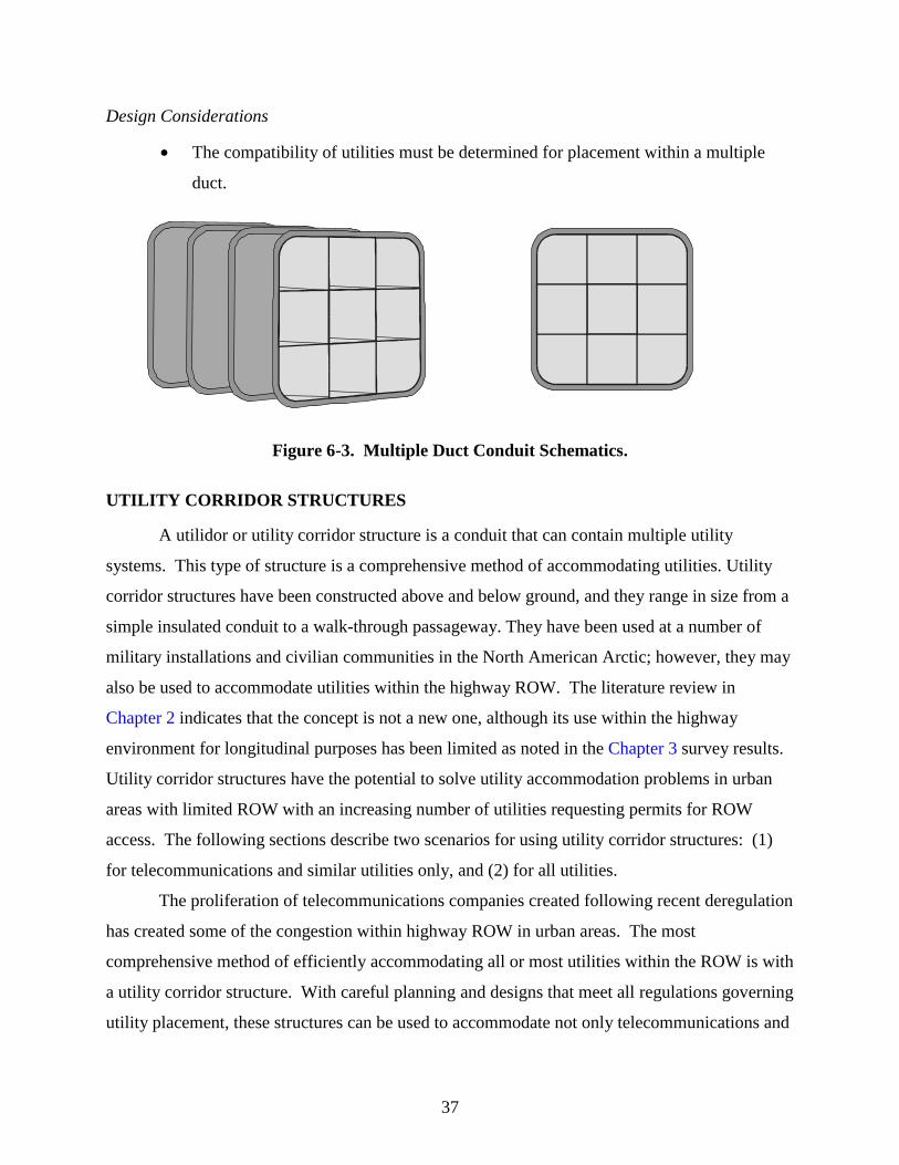
37
Design Considerations
• The compatibility of utilities must be determined for placement within a multiple
duct.
Figure 6-3. Multiple Duct Conduit Schematics.
UTILITY CORRIDOR STRUCTURES
A utilidor or utility corridor structure is a conduit that can contain multiple utility
systems. This type of structure is a comprehensive method of accommodating utilities. Utility
corridor structures have been constructed above and below ground, and they range in size from a
simple insulated conduit to a walk-through passageway. They have been used at a number of
military installations and civilian communities in the North American Arctic; however, they may
also be used to accommodate utilities within the highway ROW. The literature review in
Chapter 2 indicates that the concept is not a new one, although its use within the highway
environment for longitudinal purposes has been limited as noted in the Chapter 3 survey results.
Utility corridor structures have the potential to solve utility accommodation problems in urban
areas with limited ROW with an increasing number of utilities requesting permits for ROW
access. The following sections describe two scenarios for using utility corridor structures: (1)
for telecommunications and similar utilities only, and (2) for all utilities.
The proliferation of telecommunications companies created following recent deregulation
has created some of the congestion within highway ROW in urban areas. The most
comprehensive method of efficiently accommodating all or most utilities within the ROW is with
a utility corridor structure. With careful planning and designs that meet all regulations governing
utility placement, these structures can be used to accommodate not only telecommunications and
38
compatible utilities but also traditional utilities such as water, wastewater, natural gas, and
petroleum. In urban areas where the ROW is extremely limited and space is congested with
numerous utilities, TxDOT may want to consider using utility corridor structures for the
accommodation of all or most utilities to relieve this congestion and more effectively manage the
available ROW.
Advantages
Utility corridor structures have several benefits over both joint trenching and multi-duct
conduit.
• Utility corridor structures provide easy access to and a known location for all
utilities longitudinally along the highway ROW, thereby reducing the likelihood of
damage during subsequent highway construction or maintenance projects.
• The installation of utilities within a structure requires coordination with other
utilities, which helps reduce the utility construction and installation time. This
reduction in construction time reduces the delay to the overall project and results in
time and money savings for both TxDOT and the highway user.
• The structure can easily provide additional space for future utility additions and
expansions without significant additional costs.
Disadvantages
While utility corridor structures provide benefits for ROW management, they also present
challenges to both TxDOT and to the utility companies. These challenges include:
• Utility corridor structures may be considerably more expensive than either joint
trenching or multi-duct conduit. Large structures require additional features that are
not necessary with the other accommodation methods.
• These structures may require additional features that are not necessary with the other
accommodation methods. These features may include, but are not limited to:
o ventilation to ensure adequate air supply for workers;
o interior illumination of sufficient luminance for workers;
o drainage facilities to handle seepage or flooding; and
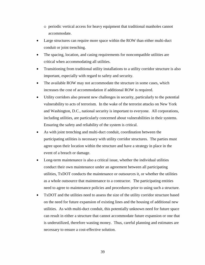
39
o periodic vertical access for heavy equipment that traditional manholes cannot
accommodate.
• Large structures can require more space within the ROW than either multi-duct
conduit or joint trenching.
• The spacing, location, and casing requirements for noncompatible utilities are
critical when accommodating all utilities.
• Transitioning from traditional utility installations to a utility corridor structure is also
important, especially with regard to safety and security.
• The available ROW may not accommodate the structure in some cases, which
increases the cost of accommodation if additional ROW is required.
• Utility corridors also present new challenges in security, particularly to the potential
vulnerability to acts of terrorism. In the wake of the terrorist attacks on New York
and Washington, D.C., national security is important to everyone. All corporations,
including utilities, are particularly concerned about vulnerabilities in their systems.
Ensuring the safety and reliability of the system is critical.
• As with joint trenching and multi-duct conduit, coordination between the
participating utilities is necessary with utility corridor structures. The parties must
agree upon their location within the structure and have a strategy in place in the
event of a breach or damage.
• Long-term maintenance is also a critical issue, whether the individual utilities
conduct their own maintenance under an agreement between all participating
utilities, TxDOT conducts the maintenance or outsources it, or whether the utilities
as a whole outsource that maintenance to a contractor. The participating entities
need to agree to maintenance policies and procedures prior to using such a structure.
• TxDOT and the utilities need to assess the size of the utility corridor structure based
on the need for future expansion of existing lines and the housing of additional new
utilities. As with multi-duct conduit, this potentially unknown need for future space
can result in either a structure that cannot accommodate future expansion or one that
is underutilized, therefore wasting money. Thus, careful planning and estimates are
necessary to ensure a cost-effective solution.
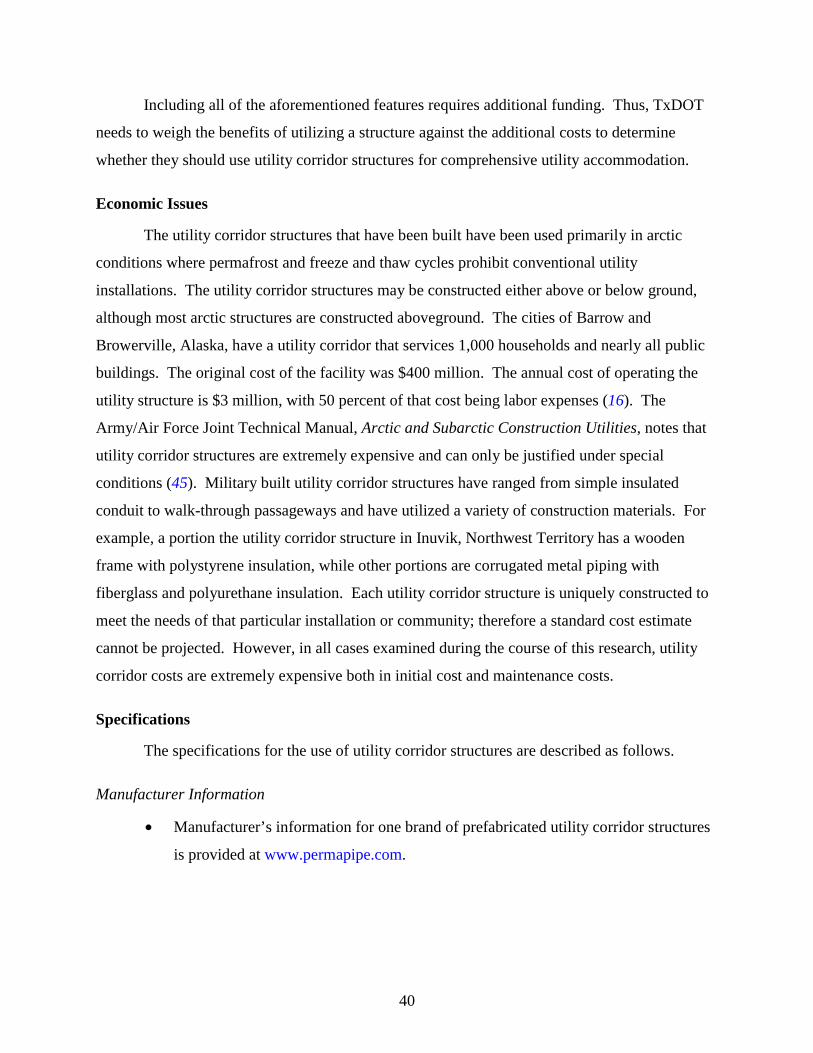
40
Including all of the aforementioned features requires additional funding. Thus, TxDOT
needs to weigh the benefits of utilizing a structure against the additional costs to determine
whether they should use utility corridor structures for comprehensive utility accommodation.
Economic Issues
The utility corridor structures that have been built have been used primarily in arctic
conditions where permafrost and freeze and thaw cycles prohibit conventional utility
installations. The utility corridor structures may be constructed either above or below ground,
although most arctic structures are constructed aboveground. The cities of Barrow and
Browerville, Alaska, have a utility corridor that services 1,000 households and nearly all public
buildings. The original cost of the facility was $400 million. The annual cost of operating the
utility structure is $3 million, with 50 percent of that cost being labor expenses (16). The
Army/Air Force Joint Technical Manual, Arctic and Subarctic Construction Utilities, notes that
utility corridor structures are extremely expensive and can only be justified under special
conditions (45). Military built utility corridor structures have ranged from simple insulated
conduit to walk-through passageways and have utilized a variety of construction materials. For
example, a portion the utility corridor structure in Inuvik, Northwest Territory has a wooden
frame with polystyrene insulation, while other portions are corrugated metal piping with
fiberglass and polyurethane insulation. Each utility corridor structure is uniquely constructed to
meet the needs of that particular installation or community; therefore a standard cost estimate
cannot be projected. However, in all cases examined during the course of this research, utility
corridor costs are extremely expensive both in initial cost and maintenance costs.
Specifications
The specifications for the use of utility corridor structures are described as follows.
Manufacturer Information
• Manufacturer’s information for one brand of prefabricated utility corridor structures
is provided at www.permapipe.com.
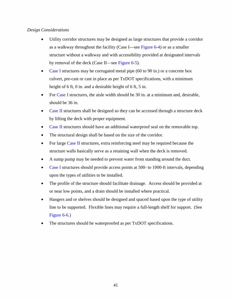
41
Design Considerations
• Utility corridor structures may be designed as large structures that provide a corridor
as a walkway throughout the facility (Case I—see Figure 6-4) or as a smaller
structure without a walkway and with accessibility provided at designated intervals
by removal of the deck (Case II—see Figure 6-5).
• Case I structures may be corrugated metal pipe (60 to 90 in.) or a concrete box
culvert, pre-cast or cast in place as per TxDOT specifications, with a minimum
height of 6 ft, 0 in. and a desirable height of 6 ft, 5 in.
• For Case I structures, the aisle width should be 30 in. at a minimum and, desirable,
should be 36 in.
• Case II structures shall be designed so they can be accessed through a structure deck
by lifting the deck with proper equipment.
• Case II structures should have an additional waterproof seal on the removable top.
• The structural design shall be based on the size of the corridor.
• For large Case II structures, extra reinforcing steel may be required because the
structure walls basically serve as a retaining wall when the deck is removed.
• A sump pump may be needed to prevent water from standing around the duct.
• Case I structures should provide access points at 500- to 1000-ft intervals, depending
upon the types of utilities to be installed.
• The profile of the structure should facilitate drainage. Access should be provided at
or near low points, and a drain should be installed where practical.
• Hangers and or shelves should be designed and spaced based upon the type of utility
line to be supported. Flexible lines may require a full-length shelf for support. (See
Figure 6-6.)
• The structures should be waterproofed as per TxDOT specifications.
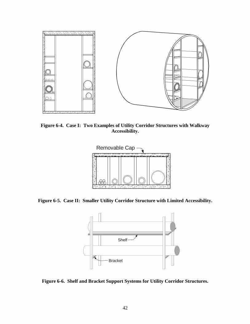
42
Figure 6-4. Case I: Two Examples of Utility Corridor Structures with Walkway Accessibility.
Figure 6-5. Case II: Smaller Utility Corridor Structure with Limited Accessibility.
Figure 6-6. Shelf and Bracket Support Systems for Utility Corridor Structures.
Removable Cap
Shelf
Bracket
43
Other Installation Requirements
Utilities installed in the ROW must comply with:
• national codes,
• TxDOT policies,
• local ordinances, and
• requirements of utility owners, including:
o power,
o cable television (CATV),
o fiber optics,
o water,
o sewer, and
o gas.
In accordance with the TxDOT Utility Accommodation Policy, installation of utilities or
utility structures must meet the requirements of Rule §21.38, which states:
Utility installations on, over, or under the right of way of the state highway system shall
conform with requirements contained herein and/or, as a minimum, the appropriate requirements
outlined in the following, whichever is greater.
(1) Safety rules for the installation and maintenance of electric supply and
communication liens – National Electric Safety Code.
(2) Title 49, Code of Federal Regulations, Part 192, Transportation of Natural and Other
Gas by Pipeline: minimum federal safety standards and amendments.
(3) Title 49, Code of Federal Regulations, Part 195, Transportation of Liquids by
Pipelines and amendments.
(4) Latest American Society for Testing and Materials (ASTM) specifications.
(5) Most recent edition of the Texas Manual on Uniform Traffic Control Devices.
(6) Latest edition of the Rules and Regulations for Public Water Systems, published by
the Texas Department of Health, Water Hygiene Division.
(7) Most recent edition of the AASHTO policy entitled “A Policy on the
Accommodations of Utilities Within Freeway Right of Way.”
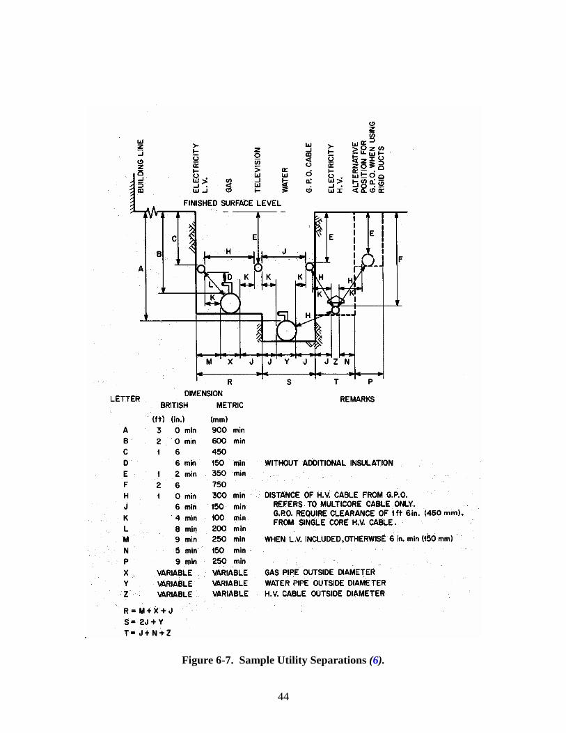
44
.
Figure 6-7. Sample Utility Separations (6).
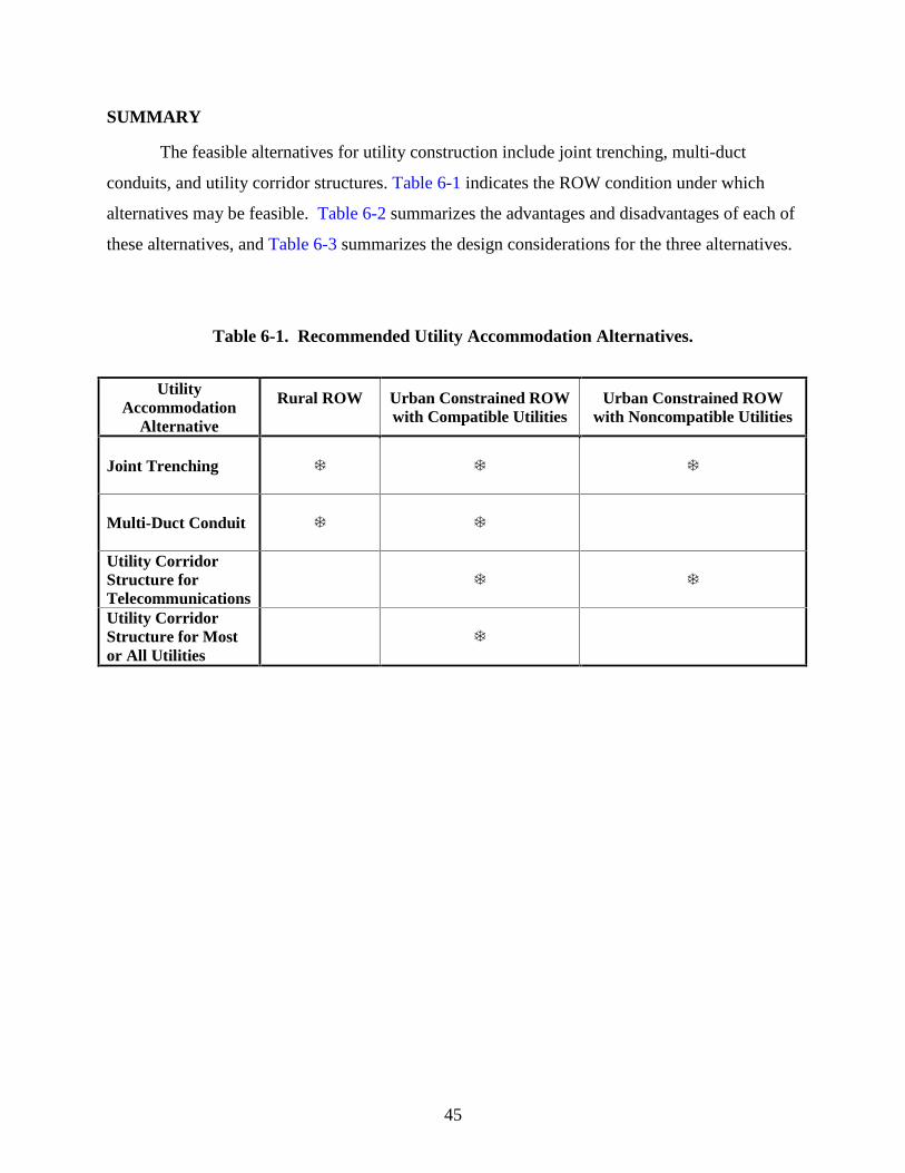
45
SUMMARY
The feasible alternatives for utility construction include joint trenching, multi-duct
conduits, and utility corridor structures. Table 6-1 indicates the ROW condition under which
alternatives may be feasible. Table 6-2 summarizes the advantages and disadvantages of each of
these alternatives, and Table 6-3 summarizes the design considerations for the three alternatives.
Table 6-1. Recommended Utility Accommodation Alternatives.
Utility Accommodation
Alternative
Rural ROW
Urban Constrained ROW with Compatible Utilities
Urban Constrained ROW with Noncompatible Utilities
Joint Trenching
� � �
Multi-Duct Conduit
� �
Utility Corridor Structure for Telecommunications
� �
Utility Corridor Structure for Most or All Utilities
�
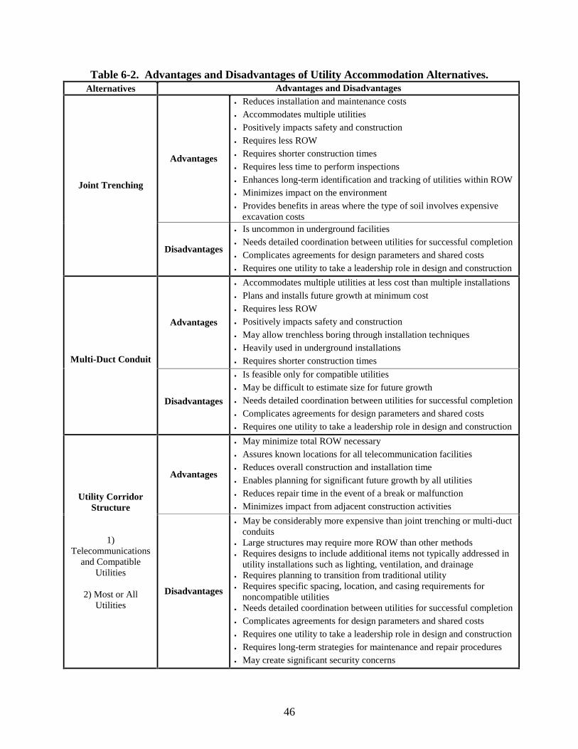
46
Table 6-2. Advantages and Disadvantages of Utility Accommodation Alternatives. Alternatives Advantages and Disadvantages
Advantages
• Reduces installation and maintenance costs • Accommodates multiple utilities • Positively impacts safety and construction • Requires less ROW • Requires shorter construction times • Requires less time to perform inspections • Enhances long-term identification and tracking of utilities within ROW • Minimizes impact on the environment • Provides benefits in areas where the type of soil involves expensive
excavation costs
Joint Trenching
Disadvantages
• Is uncommon in underground facilities • Needs detailed coordination between utilities for successful completion • Complicates agreements for design parameters and shared costs • Requires one utility to take a leadership role in design and construction
Advantages
• Accommodates multiple utilities at less cost than multiple installations • Plans and installs future growth at minimum cost • Requires less ROW • Positively impacts safety and construction • May allow trenchless boring through installation techniques • Heavily used in underground installations • Requires shorter construction times Multi-Duct Conduit
Disadvantages
• Is feasible only for compatible utilities • May be difficult to estimate size for future growth • Needs detailed coordination between utilities for successful completion • Complicates agreements for design parameters and shared costs • Requires one utility to take a leadership role in design and construction
Advantages
• May minimize total ROW necessary • Assures known locations for all telecommunication facilities • Reduces overall construction and installation time • Enables planning for significant future growth by all utilities • Reduces repair time in the event of a break or malfunction • Minimizes impact from adjacent construction activities
Utility Corridor Structure
1) Telecommunications
and Compatible Utilities
2) Most or All
Utilities
Disadvantages
• May be considerably more expensive than joint trenching or multi-duct conduits
• Large structures may require more ROW than other methods • Requires designs to include additional items not typically addressed in
utility installations such as lighting, ventilation, and drainage • Requires planning to transition from traditional utility • Requires specific spacing, location, and casing requirements for
noncompatible utilities • Needs detailed coordination between utilities for successful completion • Complicates agreements for design parameters and shared costs • Requires one utility to take a leadership role in design and construction • Requires long-term strategies for maintenance and repair procedures • May create significant security concerns
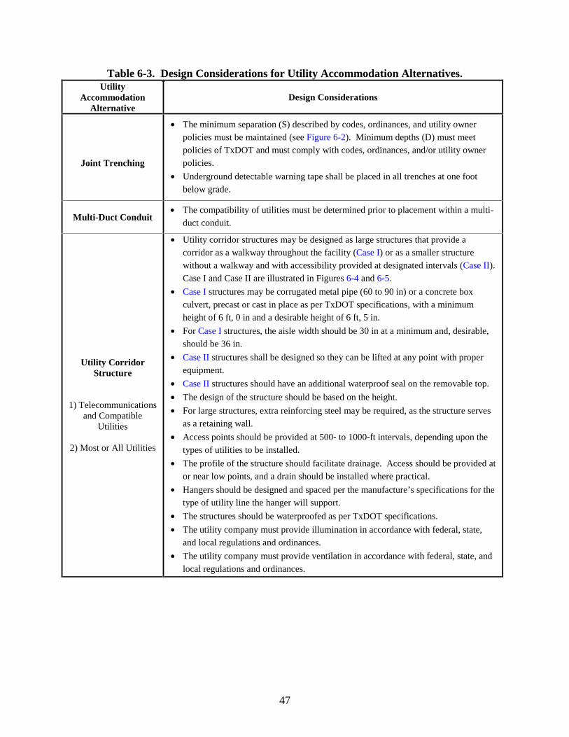
47
Table 6-3. Design Considerations for Utility Accommodation Alternatives. Utility
Accommodation Alternative
Design Considerations
Joint Trenching
• The minimum separation (S) described by codes, ordinances, and utility owner policies must be maintained (see Figure 6-2). Minimum depths (D) must meet policies of TxDOT and must comply with codes, ordinances, and/or utility owner policies.
• Underground detectable warning tape shall be placed in all trenches at one foot below grade.
Multi-Duct Conduit
• The compatibility of utilities must be determined prior to placement within a multi-duct conduit.
Utility Corridor Structure
1) Telecommunications
and Compatible Utilities
2) Most or All Utilities
• Utility corridor structures may be designed as large structures that provide a corridor as a walkway throughout the facility (Case I) or as a smaller structure without a walkway and with accessibility provided at designated intervals (Case II). Case I and Case II are illustrated in Figures 6-4 and 6-5.
• Case I structures may be corrugated metal pipe (60 to 90 in) or a concrete box culvert, precast or cast in place as per TxDOT specifications, with a minimum height of 6 ft, 0 in and a desirable height of 6 ft, 5 in.
• For Case I structures, the aisle width should be 30 in at a minimum and, desirable, should be 36 in.
• Case II structures shall be designed so they can be lifted at any point with proper equipment.
• Case II structures should have an additional waterproof seal on the removable top.
• The design of the structure should be based on the height.
• For large structures, extra reinforcing steel may be required, as the structure serves as a retaining wall.
• Access points should be provided at 500- to 1000-ft intervals, depending upon the types of utilities to be installed.
• The profile of the structure should facilitate drainage. Access should be provided at or near low points, and a drain should be installed where practical.
• Hangers should be designed and spaced per the manufacture’s specifications for the type of utility line the hanger will support.
• The structures should be waterproofed as per TxDOT specifications.
• The utility company must provide illumination in accordance with federal, state, and local regulations and ordinances.
• The utility company must provide ventilation in accordance with federal, state, and local regulations and ordinances.

49
CHAPTER 7: FINAL REMARKS
The work presented in this report highlights an important development in utility
accommodation, the use of utility corridor structures. In general, utility corridor structures can
be useful in situations where existing utility congestion or severe limitations on available ROW
offset the increased costs of building the structure. Currently, significant impediments to
utilizing this strategy in Texas exist with the need for several legislative changes, including the
acquisition of ROW, lease and occupancy agreements, and revenue potential. Products including
basic guidelines for choosing an accommodation strategy, sample specifications, and design
drawings were prepared. The research team also prepared sample legislation and change to the
Utility Accommodation Policy, focusing on giving TxDOT the legislative authority to pursue the
use of utility corridors and ROW acquisition for same, when warranted. These are all significant
advances for the purpose of TxDOT accommodating utilities within the ROW.
Where utility corridor structures are not practical, TxDOT can consider requiring public
entities to use either multi-duct conduit or joint trenching to reduce costs, installation time, and
more efficiently utilize the available ROW.
While this feasibility study has highlighted the various possibilities and general
conditions of use, more detailed analysis is required to definitively choose a particular
accommodation policy for any given situation. Detailed benefit-cost information on a project-
by-project basis is necessary to support the choices made for various accommodation needs.

51
REFERENCES 1 . Federal Aid and Design Division, Utility Adjustments and Accommodation on Federal-
Aid Highway Projects, Fourth Edition, Federal Highway Administration, Washington, D.C., March 1998.
2 . AASHTO, A Policy on the Accommodation of Utilities on the National System of
Interstate and Defense Highways, American Association of State Highway and Transportation Officials, Washington, D.C., 1959.
3. R.L. Williams, Longitudinal Occupancy of Controlled Access Right-of-Way by Utilities,
Synthesis of Highway Practice 224, National Cooperative Highway Research Program, National Academy Press, Washington, D.C., 1996.
4 . Texas Administrative Code, Title 43-Transportation, Part 1: Texas Department of
Transportation, Chapter 21: Right of Way, Subchapter C: Utility Accommodation, 2001. 5 . Chap. 181, Texas Utility Code, 2002. 6 . W. J. Boegly, Jr., W. L. Griffith, and A. L. Compere, “Common Trenching-State of the
Art,” Transportation Research Record 571, Transportation Research Board, National Research Council, Washington, D.C., 1976.
7 . J. Campbell, “Exceptions to the Utility Accommodation Policy Will be Granted Only
Under Exceptional Circumstances,” The Utility Focus, Volume 1, Number 2, Texas Department of Transportation, Houston District, Houston, Texas, April 1999.
8 . AASHTO Task Force on Fiber Optics on Transportation Rights-of-Way, Guidance on
Sharing Freeway and Highway Rights-of-Way for Telecommunications, American Association of State Highway and Transportation Officials, Washington, D.C., 1996.
9 . M. Tubb, “Joint Trench Construction, Solves Utility Dilemma in High-Tech Corridor,”
Underground Construction, Volume 54, Number 9, Pages 27-32, Oildom Publishing Company of Texas, Houston, Texas, September 1999.
10 . Webster’s New Collegiate Dictionary, G. & C. Merriam Company, Springfield,
Massachusetts, 1977. 11 . Our History and Culture, The Williams Companies, Inc., Tulsa, Oklahoma, Website
http://www.williams.com/information/inf_history.html, 2001. 12 . Company Overview and History, Williams Communications, Tulsa, Oklahoma, Website,
http://www.williamscommunications.com/overview, 2001. 13 . Urban Explorers Website and links, http://www.urbanexplorers.net/, 2001.
52
14 . Pollution Prevention Branch, “Preventing Frozen Water Pipes,” Manitoba Environment
Information Bulletin, Bulletin 96-14E, Manitoba Environment, Winnipeg, British Columbia, November 1996.
15 . Perma-Pipe, Heating and Cooling Services; Tunnels; Utilidor, Perma-pipe a subsidiary of
MFRI, Inc., Website www.permapipe.com, 2001. 16 . L. Kidder, Barrow, Alaska from A to Z, Bonaparte Books, Barrow, AK, 2001. 17 . A. Firmin, B. Gibson, and J. Swope, “Going Underground: Myths and Facts of the UAF
Utilidors,” The Heartland Magazine, The Fairbanks Daily News-Miner. 18 . T. R. Shaw, Under the Magic Kingdom, The Hidden Mickey Website,
http://www.hiddenmickey.org, 2001. 19 . D.M. Bresnahan, Systems Manager for Operations and Logistics, Workshop and
Presentation for Bidders, National Science Foundation, Washington, D.C., September 1998.
20 . Photographs from Construction of South Pole Utilidor, Courtesy of Jerry Marty, Carlton
Walker, Floyd Washington, Slay Harwell, and Tom Edwards, National Science Foundation Research Team, August 20, 2002.
21 . D. Perez, “Downtown Cleanup/Downtown’s Tunnel System Recovers from Flooding,
Houston Chronicle, Houston, Texas, Thursday, June 14, 2001. 22 . L. B. Parks and M. D. Clark, “Theater District Powerless to Get the Shows on the Road,”
Houston Chronicle, Houston, Texas, Friday, June 15, 2001. 23 . Project Development Process Manual, Texas Department of Transportation Website,
http://www.dot.state.tx.us, Austin, TX, July 2001. 24. Average Low Bid Unit Price - Construction – (Statewide), Texas Department of
Transportation Website, http://www.dot.state.tx.us/business/Avgd.Htm, June 2002. 25. Sec. 203.051, Texas Transportation Code, 2002. 26. Sec. 203.052, Texas Transportation Code, 2002. 27. Roadway Design Manual, Texas Department of Transportation Website,
http://www.dot.state.tx.us, Austin, TX, April 2002. 28 . Sec. 202.052, Texas Transportation Code, 2002.
53
29 . 26 United States Code, Sec. 115, 2002. 30 . Shared Resources: Sharing Right-of-Way for Telecommunications Guidance on Legal
and Institutional Issues, Report FHWA-JPO-96-0015, U.S. Department of Transportation, Federal Highway Administration, 1996.
31 . Texas Administrative Code, Title 43-Transportation, Part 1: Texas Department of
Transportation, Chapter 21: Right of Way, Subchapter C: Utility Accommodation, 2002. 32 . Sec. 21.47, Texas Administrative Code, Title 43-Transportation, Part 1: Texas
Department of Transportation, Chapter 21: Right of Way, Subchapter C: Utility Accommodation, 2002.
33 . A.R. McDonald, “Success in the Trenches,” Transmission and Distribution World,
Primedia Business Magazines & Media, December 2001. 34 . R. Murray, “Joint trenching,” Municipal News, Union Gas, March 2002, p. 2. 35 . “Southwest Gas Brings Gas to Prosser,” Press Release, Southwest Gas Corporation,
August 2000. 36 . “Benefits of a Joint Trenching System,” The Conduit, TXU Electric & Gas, Vol. 1, Issue
1, May 2000, p. 3. 37 . “Enbridge Consumers Gas Joint Utility Construction in Residential Subdivision,”
Builder’s Technical Bulletin, Enbridge Consumers Gas, December 2001. 38 . OUCC Joint Trench Examples, Oregon Utility Notification Center Website,
http://www.digsafelyorgon.com/digsafe/ds/ds_joint_trench.htm, 3 July 2002. 39 . “Joint Trenching: Construction Facts,” Gas Utility Manager, James Informational
Media, Inc., Des Plaines, IL, September 1999. 40 . HNTB Engineering & Architecture, P.D. and S.G. Associates, Inc., Intelligent
Transportation Systems Early Deployment Planning Study, New York State Department of Transportation Lower Hudson Valley, Region 8, November 1998.
41 . W. Siembab, S. Graham, and M. Roldan, Using Fiber Networks to Stimulate Transit
Oriented Development: Prospects, Barriers and Best Practices, MTI Report O1-16, Mineta Transportation Institute, College of Business, San Jose State University, San Jose, CA, October 2001.
42 . E.C. Reagle, “DMJM+HARRIS: I-676 (Vine Expressway) Traffic and Incident
Management System,” MASITE Interconnect, Mid-Atlantic Section, Institute of Transportation Engineers, Vol. 6, No. 4, November 2001, pp. 4-6.
54
43 . Light Link Networks Website, http://www.lightlinknetworks.com, 10 July 2002. 44 . “Trenchless Installations Grow in India,” No-Dig International, Nodigindia.com
Website, http://www.nodigindia.com/case_inter1.html, April 2001. 45. Departments of the Army and the Air Force, Arctic and Subarctic Construction Utilities,
Technical Manual, Army TM 5-285-2, Air Force AFR 88-19, Volume 5, US Department of Defense, Washington, D.C., August 1987.

55
APPENDIX A: UTILITY CORRIDOR QUESTIONNAIRE

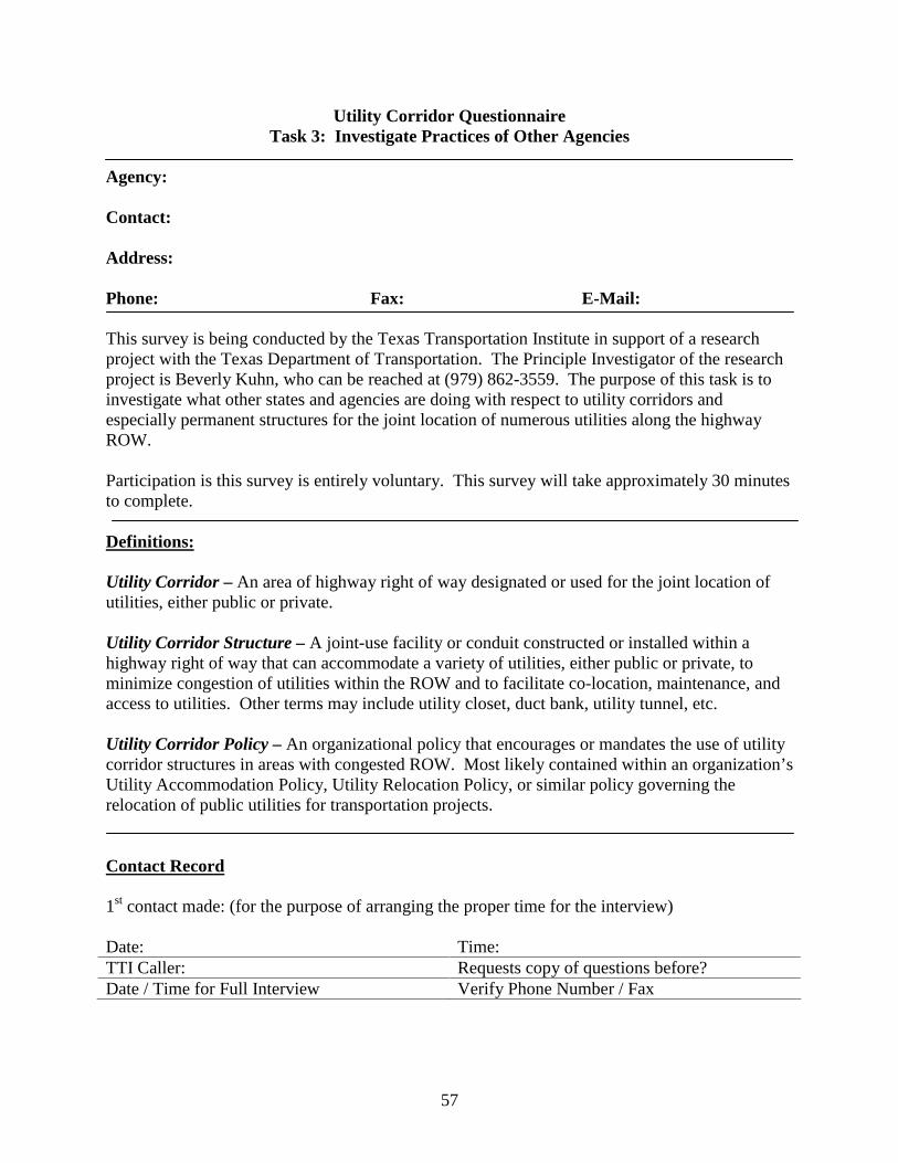
57
Utility Corridor Questionnaire Task 3: Investigate Practices of Other Agencies
Agency: Contact: Address: Phone: Fax: E-Mail:
This survey is being conducted by the Texas Transportation Institute in support of a research project with the Texas Department of Transportation. The Principle Investigator of the research project is Beverly Kuhn, who can be reached at (979) 862-3559. The purpose of this task is to investigate what other states and agencies are doing with respect to utility corridors and especially permanent structures for the joint location of numerous utilities along the highway ROW. Participation is this survey is entirely voluntary. This survey will take approximately 30 minutes to complete. Definitions: Utility Corridor – An area of highway right of way designated or used for the joint location of utilities, either public or private. Utility Corridor Structure – A joint-use facility or conduit constructed or installed within a highway right of way that can accommodate a variety of utilities, either public or private, to minimize congestion of utilities within the ROW and to facilitate co-location, maintenance, and access to utilities. Other terms may include utility closet, duct bank, utility tunnel, etc. Utility Corridor Policy – An organizational policy that encourages or mandates the use of utility corridor structures in areas with congested ROW. Most likely contained within an organization’s Utility Accommodation Policy, Utility Relocation Policy, or similar policy governing the relocation of public utilities for transportation projects. Contact Record
1st contact made: (for the purpose of arranging the proper time for the interview) Date: Time: TTI Caller: Requests copy of questions before? Date / Time for Full Interview Verify Phone Number / Fax
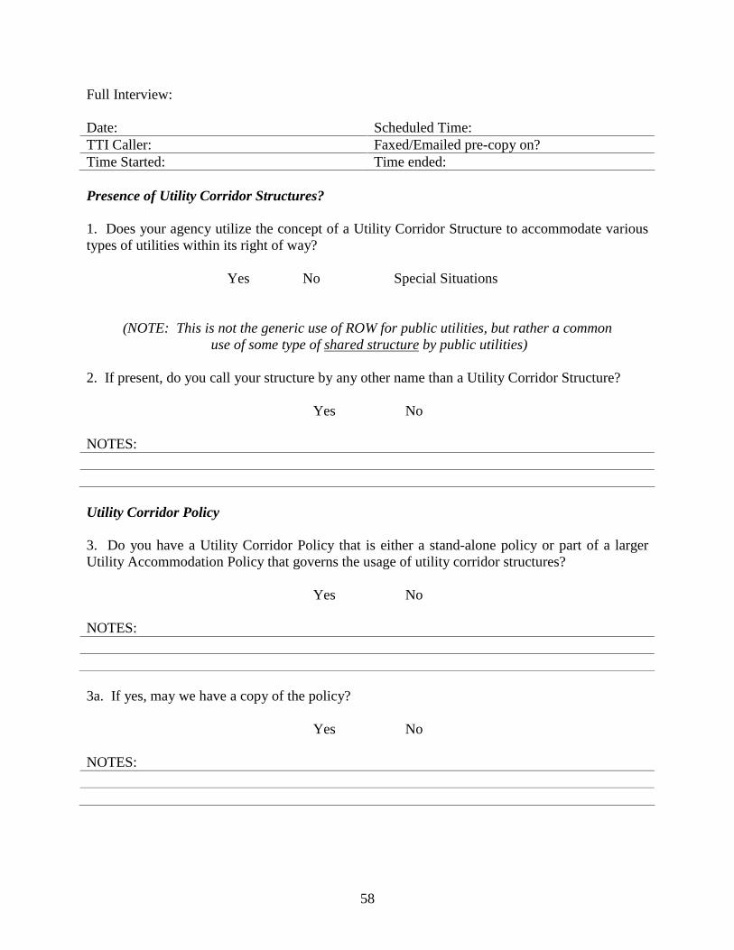
58
Full Interview: Date: Scheduled Time: TTI Caller: Faxed/Emailed pre-copy on? Time Started: Time ended: Presence of Utility Corridor Structures? 1. Does your agency utilize the concept of a Utility Corridor Structure to accommodate various types of utilities within its right of way?
Yes No Special Situations
(NOTE: This is not the generic use of ROW for public utilities, but rather a common use of some type of shared structure by public utilities)
2. If present, do you call your structure by any other name than a Utility Corridor Structure?
Yes No
NOTES: Utility Corridor Policy 3. Do you have a Utility Corridor Policy that is either a stand-alone policy or part of a larger Utility Accommodation Policy that governs the usage of utility corridor structures?
Yes No
NOTES: 3a. If yes, may we have a copy of the policy?
Yes No NOTES:
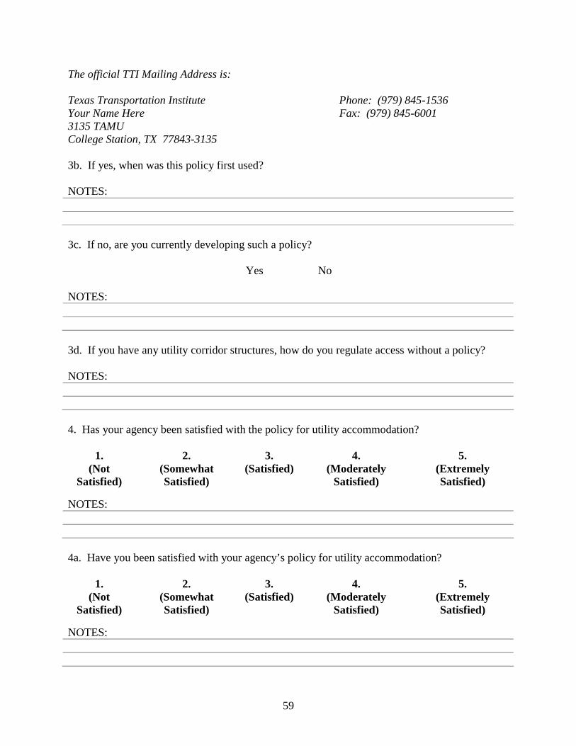
59
The official TTI Mailing Address is: Texas Transportation Institute Phone: (979) 845-1536 Your Name Here Fax: (979) 845-6001 3135 TAMU College Station, TX 77843-3135 3b. If yes, when was this policy first used? NOTES: 3c. If no, are you currently developing such a policy?
Yes No NOTES: 3d. If you have any utility corridor structures, how do you regulate access without a policy? NOTES: 4. Has your agency been satisfied with the policy for utility accommodation?
1. (Not
Satisfied)
2. (Somewhat Satisfied)
3. (Satisfied)
4. (Moderately
Satisfied)
5. (Extremely Satisfied)
NOTES: 4a. Have you been satisfied with your agency’s policy for utility accommodation?
1. (Not
Satisfied)
2. (Somewhat Satisfied)
3. (Satisfied)
4. (Moderately
Satisfied)
5. (Extremely Satisfied)
NOTES:
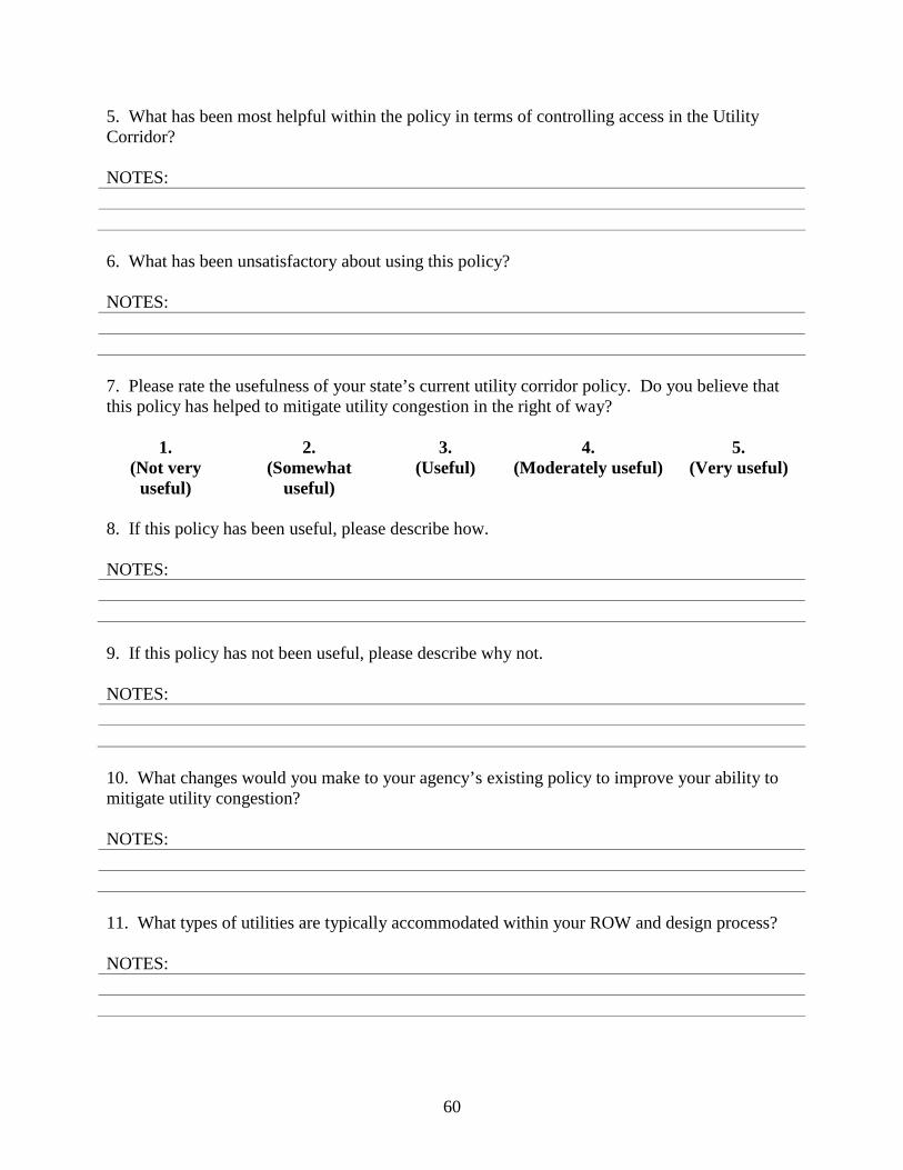
60
5. What has been most helpful within the policy in terms of controlling access in the Utility Corridor? NOTES: 6. What has been unsatisfactory about using this policy? NOTES: 7. Please rate the usefulness of your state’s current utility corridor policy. Do you believe that this policy has helped to mitigate utility congestion in the right of way?
1.
(Not very useful)
2. (Somewhat
useful)
3. (Useful)
4. (Moderately useful)
5. (Very useful)
8. If this policy has been useful, please describe how. NOTES: 9. If this policy has not been useful, please describe why not. NOTES: 10. What changes would you make to your agency’s existing policy to improve your ability to mitigate utility congestion? NOTES: 11. What types of utilities are typically accommodated within your ROW and design process? NOTES:
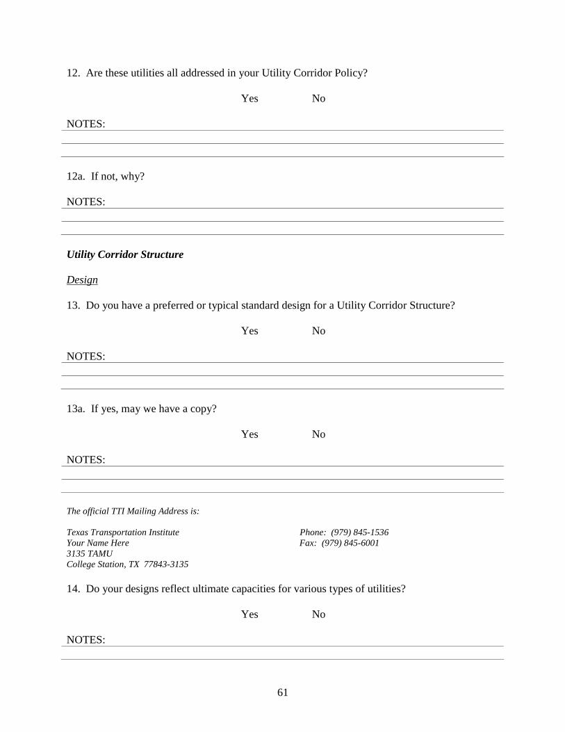
61
12. Are these utilities all addressed in your Utility Corridor Policy?
Yes No NOTES: 12a. If not, why? NOTES: Utility Corridor Structure Design 13. Do you have a preferred or typical standard design for a Utility Corridor Structure?
Yes No NOTES: 13a. If yes, may we have a copy?
Yes No NOTES: The official TTI Mailing Address is: Texas Transportation Institute Phone: (979) 845-1536 Your Name Here Fax: (979) 845-6001 3135 TAMU College Station, TX 77843-3135 14. Do your designs reflect ultimate capacities for various types of utilities?
Yes No NOTES:
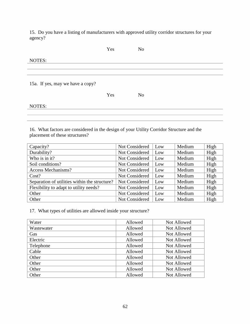
62
15. Do you have a listing of manufacturers with approved utility corridor structures for your agency?
Yes No NOTES: 15a. If yes, may we have a copy?
Yes No NOTES: 16. What factors are considered in the design of your Utility Corridor Structure and the placement of these structures? Capacity? Not Considered Low Medium High Durability? Not Considered Low Medium High Who is in it? Not Considered Low Medium High Soil conditions? Not Considered Low Medium High Access Mechanisms? Not Considered Low Medium High Cost? Not Considered Low Medium High Separation of utilities within the structure? Not Considered Low Medium High Flexibility to adapt to utility needs? Not Considered Low Medium High Other Not Considered Low Medium High Other Not Considered Low Medium High 17. What types of utilities are allowed inside your structure? Water Allowed Not Allowed Wastewater Allowed Not Allowed Gas Allowed Not Allowed Electric Allowed Not Allowed Telephone Allowed Not Allowed Cable Allowed Not Allowed Other Allowed Not Allowed Other Allowed Not Allowed Other Allowed Not Allowed Other Allowed Not Allowed
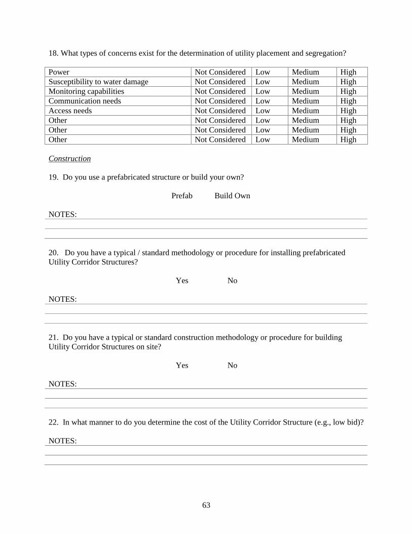
63
18. What types of concerns exist for the determination of utility placement and segregation? Power Not Considered Low Medium High Susceptibility to water damage Not Considered Low Medium High Monitoring capabilities Not Considered Low Medium High Communication needs Not Considered Low Medium High Access needs Not Considered Low Medium High Other Not Considered Low Medium High Other Not Considered Low Medium High Other Not Considered Low Medium High Construction 19. Do you use a prefabricated structure or build your own?
Prefab Build Own NOTES: 20. Do you have a typical / standard methodology or procedure for installing prefabricated Utility Corridor Structures?
Yes No NOTES: 21. Do you have a typical or standard construction methodology or procedure for building Utility Corridor Structures on site?
Yes No NOTES: 22. In what manner to do you determine the cost of the Utility Corridor Structure (e.g., low bid)? NOTES:
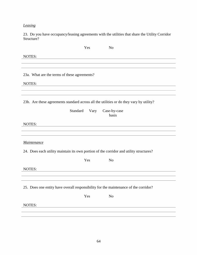
64
Leasing 23. Do you have occupancy/leasing agreements with the utilities that share the Utility Corridor Structure?
Yes No NOTES: 23a. What are the terms of these agreements? NOTES: 23b. Are these agreements standard across all the utilities or do they vary by utility?
Standard Vary Case-by-case basis
NOTES: Maintenance 24. Does each utility maintain its own portion of the corridor and utility structures?
Yes No NOTES: 25. Does one entity have overall responsibility for the maintenance of the corridor?
Yes No NOTES:

65
25a. Who has that responsibility? NOTES: 25b. How is that responsibility decided (e.g., Is it the responsibility of the first utility to locate in the ROW)? NOTES: 26. What is the procedure for alerting other utilities of maintenance issues that may affect their services? NOTES: Legal 27. What legal barriers, if any, had to be overcome before your agency could use a Utility Corridor Policy? NOTES: Cost 28. How is your Utility Corridor funded? Part of highway construction? Yes No In part At times Utility financed? Yes No In part At times Separate funding pool? Yes No In part At times Other Yes No In part At times Other Yes No In part At times NOTES:
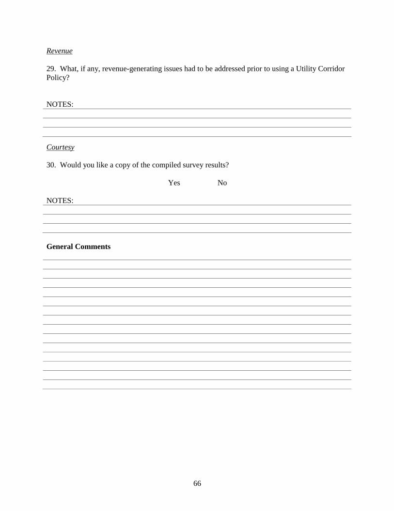
66
Revenue 29. What, if any, revenue-generating issues had to be addressed prior to using a Utility Corridor Policy? NOTES:
Courtesy 30. Would you like a copy of the compiled survey results?
Yes No NOTES: General Comments

67
APPENDIX B: INVESTIGATION OF PRACTICES OF OTHER AGENCIES

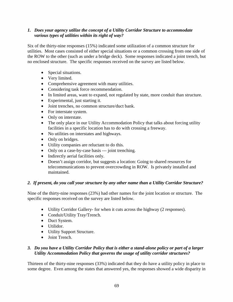
69
1. Does your agency utilize the concept of a Utility Corridor Structure to accommodate various types of utilities within its right of way?
Six of the thirty-nine responses (15%) indicated some utilization of a common structure for utilities. Most cases consisted of either special situations or a common crossing from one side of the ROW to the other (such as under a bridge deck). Some responses indicated a joint trench, but no enclosed structure. The specific responses received on the survey are listed below.
• Special situations. • Very limited. • Comprehensive agreement with many utilities. • Considering task force recommendation. • In limited areas, want to expand, not regulated by state, more conduit than structure. • Experimental, just starting it. • Joint trenches, no common structure/duct bank. • For interstate system. • Only on interstate. • The only place in our Utility Accommodation Policy that talks about forcing utility
facilities in a specific location has to do with crossing a freeway. • No utilities on interstates and highways. • Only on bridges. • Utility companies are reluctant to do this. • Only on a case-by-case basis --- joint trenching. • Indirectly aerial facilities only. • Doesn’t assign corridor, but suggests a location: Going to shared resources for
telecommunications to prevent overcrowding in ROW. Is privately installed and maintained.
2. If present, do you call your structure by any other name than a Utility Corridor Structure? Nine of the thirty-nine responses (23%) had other names for the joint location or structure. The specific responses received on the survey are listed below.
• Utility Corridor Gallery- for when it cuts across the highway (2 responses). • Conduit/Utility Tray/Trench. • Duct System. • Utilidor. • Utility Support Structure. • Joint Trench.
3. Do you have a Utility Corridor Policy that is either a stand-alone policy or part of a larger
Utility Accommodation Policy that governs the usage of utility corridor structures? Thirteen of the thirty-nine responses (33%) indicated that they do have a utility policy in place to some degree. Even among the states that answered yes, the responses showed a wide disparity in
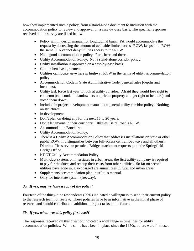
70
how they implemented such a policy, from a stand-alone document to inclusion with the accommodation policy to review and approval on a case-by-case basis. The specific responses received on the survey are listed below.
• Policy within design manual for longitudinal basis. PA would accommodate the request by decreasing the amount of available limited access ROW, keeps total ROW the same. PA cannot deny utilities access to the ROW.
• Not a good accommodation policy. Parts here and there. • Utility Accommodation Policy. Not a stand-alone corridor policy. • Utility installation is approved on a case-by-case basis. • Comprehensive agreement. • Utilities can locate anywhere in highway ROW in the terms of utility accommodation
policy. • Accommodation Code in State Administrative Code, general rules (depths and
locations). • Utility task force last year to look at utility corridor. Afraid they would lose right to
condemn (can condemn landowners on private property and get right to be there) and voted them down.
• Included in project development manual is a general utility corridor policy. Nothing on structures.
• In development. • Don’t plan on doing any for the next 15 to 20 years. • Don’t let anyone in their corridors! Utilities use railroad’s ROW. • Accommodation Brochure. • Utility Accommodation Policy. • There is a Utility Accommodation Policy that addresses installations on state or other
public ROW. It distinguishes between full-access central roadways and all others. District offices review permits. Bridge attachment requests go to the Springfield Bridge Office.
• KDOT Utility Accommodation Policy. • Multi-duct system, on interstates in urban areas, the first utility company is required
to pay for the ducts and recoup their costs from other utilities. So far no second utilities have gone in, also charged are annual fees in rural and urban areas.
• Supplements accommodation plan in utilities manual. • Only for interstate system (freeway).
3a. If yes, may we have a copy of the policy? Fourteen of the thirty-nine respondents (39%) indicated a willingness to send their current policy to the research team for review. These policies have been informative in the initial phase of research and should contribute to additional project tasks in the future. 3b. If yes, when was this policy first used? The responses received on this question indicated a wide range in timelines for utility accommodation policies. While some have been in place since the 1950s, others were first used
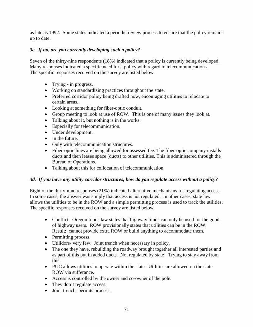
71
as late as 1992. Some states indicated a periodic review process to ensure that the policy remains up to date. 3c. If no, are you currently developing such a policy? Seven of the thirty-nine respondents (18%) indicated that a policy is currently being developed. Many responses indicated a specific need for a policy with regard to telecommunications. The specific responses received on the survey are listed below.
• Trying - in progress. • Working on standardizing practices throughout the state. • Preferred corridor policy being drafted now, encouraging utilities to relocate to
certain areas. • Looking at something for fiber-optic conduit. • Group meeting to look at use of ROW. This is one of many issues they look at. • Talking about it, but nothing is in the works. • Especially for telecommunication. • Under development. • In the future. • Only with telecommunication structures. • Fiber-optic lines are being allowed for assessed fee. The fiber-optic company installs
ducts and then leases space (ducts) to other utilities. This is administered through the Bureau of Operations.
• Talking about this for collocation of telecommunication. 3d. If you have any utility corridor structures, how do you regulate access without a policy?
Eight of the thirty-nine responses (21%) indicated alternative mechanisms for regulating access. In some cases, the answer was simply that access is not regulated. In other cases, state law allows the utilities to be in the ROW and a simple permitting process is used to track the utilities. The specific responses received on the survey are listed below.
• Conflict: Oregon funds law states that highway funds can only be used for the good of highway users. ROW provisionally states that utilities can be in the ROW. Result: cannot provide extra ROW or build anything to accommodate them.
• Permitting process. • Utilidors- very few. Joint trench when necessary in policy. • The one they have, rebuilding the roadway brought together all interested parties and
as part of this put in added ducts. Not regulated by state! Trying to stay away from this.
• PUC allows utilities to operate within the state. Utilities are allowed on the state ROW via sufferance.
• Access is controlled by the owner and co-owner of the pole. • They don’t regulate access. • Joint trench- permits process.
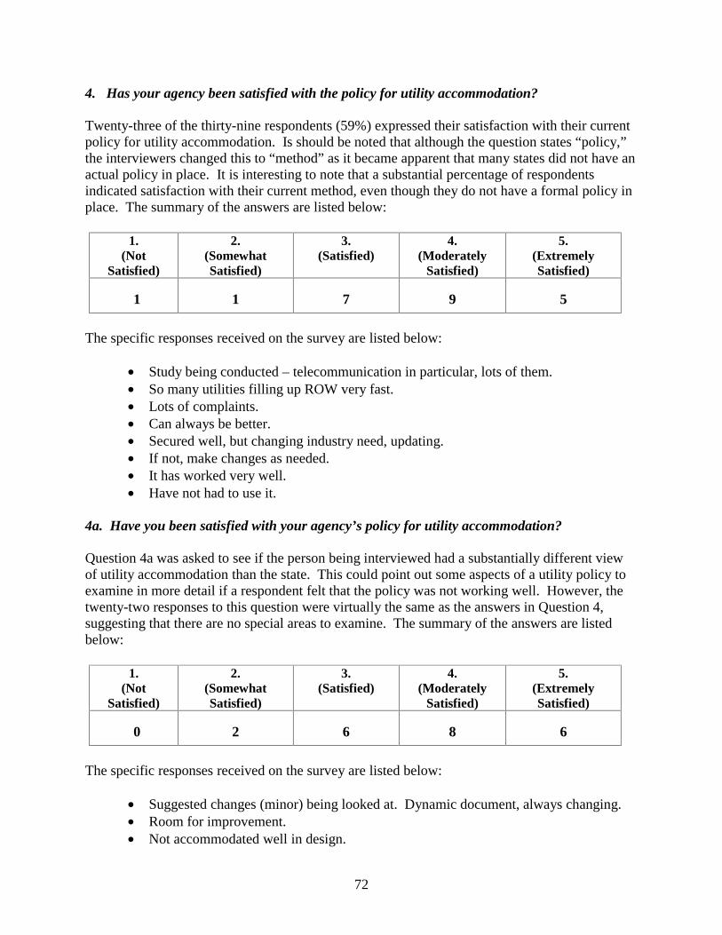
72
4. Has your agency been satisfied with the policy for utility accommodation? Twenty-three of the thirty-nine respondents (59%) expressed their satisfaction with their current policy for utility accommodation. Is should be noted that although the question states “policy,” the interviewers changed this to “method” as it became apparent that many states did not have an actual policy in place. It is interesting to note that a substantial percentage of respondents indicated satisfaction with their current method, even though they do not have a formal policy in place. The summary of the answers are listed below:
1. (Not
Satisfied)
2. (Somewhat Satisfied)
3. (Satisfied)
4. (Moderately
Satisfied)
5. (Extremely Satisfied)
1 1 7 9 5
The specific responses received on the survey are listed below:
• Study being conducted – telecommunication in particular, lots of them. • So many utilities filling up ROW very fast. • Lots of complaints. • Can always be better. • Secured well, but changing industry need, updating. • If not, make changes as needed. • It has worked very well. • Have not had to use it.
4a. Have you been satisfied with your agency’s policy for utility accommodation? Question 4a was asked to see if the person being interviewed had a substantially different view of utility accommodation than the state. This could point out some aspects of a utility policy to examine in more detail if a respondent felt that the policy was not working well. However, the twenty-two responses to this question were virtually the same as the answers in Question 4, suggesting that there are no special areas to examine. The summary of the answers are listed below:
1. (Not
Satisfied)
2. (Somewhat Satisfied)
3. (Satisfied)
4. (Moderately
Satisfied)
5. (Extremely Satisfied)
0 2 6 8 6
The specific responses received on the survey are listed below:
• Suggested changes (minor) being looked at. Dynamic document, always changing. • Room for improvement. • Not accommodated well in design.
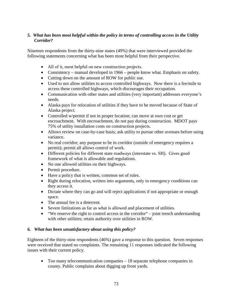
73
5. What has been most helpful within the policy in terms of controlling access in the Utility
Corridor? Nineteen respondents from the thirty-nine states (49%) that were interviewed provided the following statements concerning what has been most helpful from their perspective.
• All of it, most helpful on new construction projects. • Consistency – manual developed in 1966 – people know what. Emphasis on safety. • Cutting down on the amount of ROW for public use. • Used to not allow utilities to access controlled highways. Now there is a fee/mile to
access these controlled highways, which discourages their occupation. • Communication with other states and utilities (very important) addresses everyone’s
needs. • Alaska pays for relocation of utilities if they have to be moved because of State of
Alaska project. • Controlled w/permit if not in proper location; can move at own cost or get
encroachment. With encroachment, do not pay during construction. MDOT pays 75% of utility installation costs on construction projects.
• Allows review on case-by-case basis; ask utility to pursue other avenues before using variance.
• No real corridor; any purpose to be in corridor (outside of emergency requires a permit); permit all allows control of work.
• Different policies for different state roadways (interstate vs. SH). Gives good framework of what is allowable and regulations.
• No one allowed utilities on their highways. • Permit procedure. • Have a policy that is written, common set of rules. • Right during relocation, written into arguments, only in emergency conditions can
they access it. • Dictate where they can go and will reject applications if not appropriate or enough
space. • The annual fee is a deterrent. • Severe limitations as far as what is allowed and placement of utilities. • “We reserve the right to control access in the corridor” – joint trench understanding
with other utilities; retain authority over utilities in ROW. 6. What has been unsatisfactory about using this policy? Eighteen of the thirty-nine respondents (46%) gave a response to this question. Seven responses were received that stated no complaints. The remaining 11 responses indicated the following issues with their current policy.
• Too many telecommunication companies – 18 separate telephone companies in county. Public complains about digging up front yards.
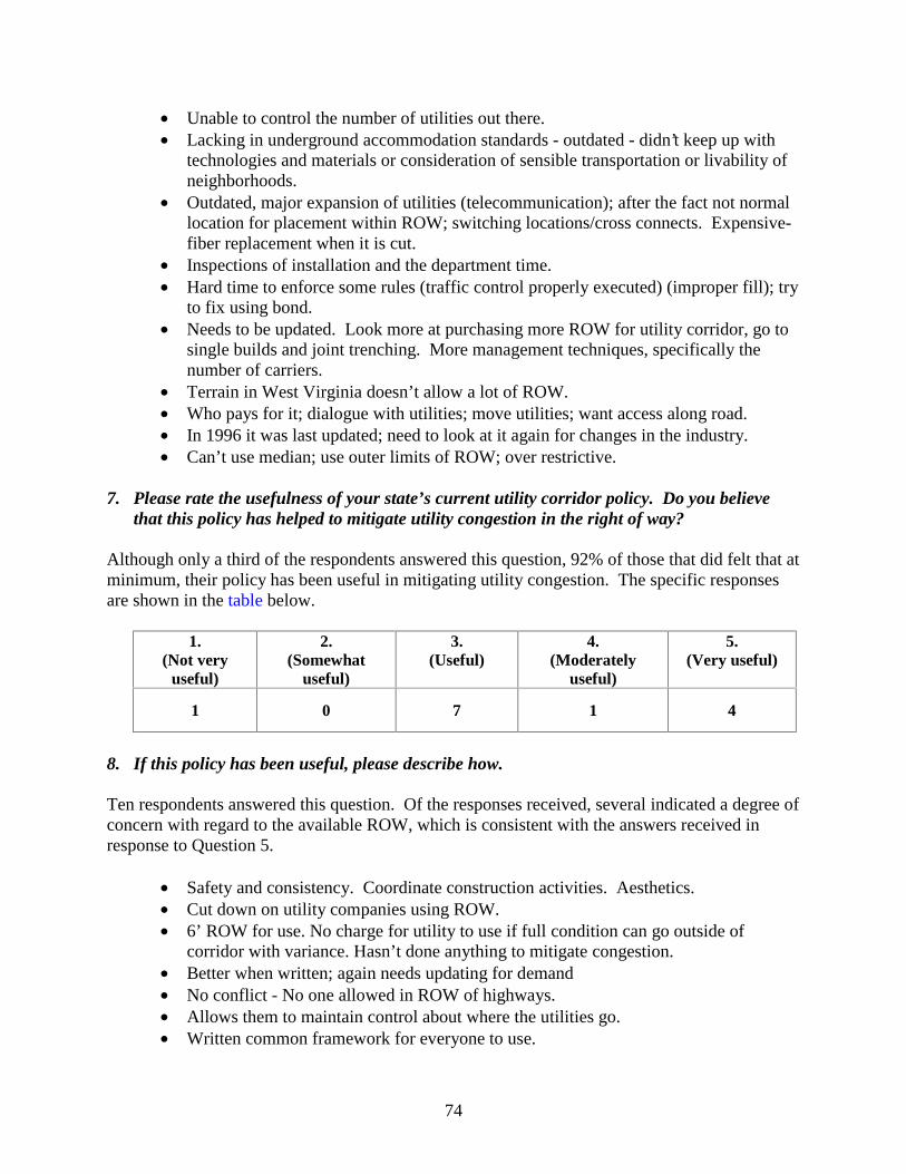
74
• Unable to control the number of utilities out there. • Lacking in underground accommodation standards - outdated - didn’t keep up with
technologies and materials or consideration of sensible transportation or livability of neighborhoods.
• Outdated, major expansion of utilities (telecommunication); after the fact not normal location for placement within ROW; switching locations/cross connects. Expensive- fiber replacement when it is cut.
• Inspections of installation and the department time. • Hard time to enforce some rules (traffic control properly executed) (improper fill); try
to fix using bond. • Needs to be updated. Look more at purchasing more ROW for utility corridor, go to
single builds and joint trenching. More management techniques, specifically the number of carriers.
• Terrain in West Virginia doesn’t allow a lot of ROW. • Who pays for it; dialogue with utilities; move utilities; want access along road. • In 1996 it was last updated; need to look at it again for changes in the industry. • Can’t use median; use outer limits of ROW; over restrictive.
7. Please rate the usefulness of your state’s current utility corridor policy. Do you believe
that this policy has helped to mitigate utility congestion in the right of way? Although only a third of the respondents answered this question, 92% of those that did felt that at minimum, their policy has been useful in mitigating utility congestion. The specific responses are shown in the table below.
1.
(Not very useful)
2. (Somewhat
useful)
3. (Useful)
4. (Moderately
useful)
5. (Very useful)
1 0 7 1 4
8. If this policy has been useful, please describe how. Ten respondents answered this question. Of the responses received, several indicated a degree of concern with regard to the available ROW, which is consistent with the answers received in response to Question 5.
• Safety and consistency. Coordinate construction activities. Aesthetics. • Cut down on utility companies using ROW. • 6’ ROW for use. No charge for utility to use if full condition can go outside of
corridor with variance. Hasn’t done anything to mitigate congestion. • Better when written; again needs updating for demand • No conflict - No one allowed in ROW of highways. • Allows them to maintain control about where the utilities go. • Written common framework for everyone to use.
75
• Only an accommodation policy; accommodates everyone on ROW without a corridor.
• Controls who and why is going where and do they have to go in? Looks at safety and other alternatives, also looks at maintenance issues.
• Conserving valuable ROW space. 9. If this policy has not been useful, please describe why not. Four respondents answered this question from the thirty-nine interviews. Interestingly, all four responses were virtually the same, indicating an issue with the number of telecommunications companies located in the ROW.
• Too many telecommunication companies in ROW.
10. What changes would you make to your agency’s existing policy to improve your ability to
mitigate utility congestion? Despite the fact that more than 50% of the respondents indicated satisfaction with their current policy, on both an agency and personal level, sixteen of the thirty-nine respondents (41%) indicated that they would make some changes. The listing of changes is below:
• More front-end design work. Work the utility relocation into the construction contracts.
• Greater use of subsurface utility engineering in the design phase. Create utility corridors separate from highway ROW. Would allow you to relocate utilities pre-construction and give contractor a clean ROW to work in.
• Restrict the number of facilities any one company can place. Disallow abandonment within the ROW.
• Right to deny utility companies access. Fewer utilities in the ROW. • Recommend changing policy to require utilities to design facilities for future
relocation during highway projects. • None at this time. Can go on private easement. • Come up with a good definition of “utilities” to categorize. Look at joint ventures to
relieve congestion. • Formal utilization to establish a utility corridor. Give DOT ability of obtaining ROW
for utilities. • Allow utilities more space than they need to allow them to co-locate with other
utilities in the same utility duct bank. • Specifically designate where each type of utility could be placed. • Currently in the process of rewriting their policy. They are considering a “structure;”
it is complicated to figure out who would pay for it, especially on non-interstate roadways.
• Be able to buy additional ROW for utilities only. • Explore utility corridor structures.
76
11. What types of utilities are typically accommodated within your ROW and design process? Twenty-eight of the thirty-nine respondents (72%) offered clarification as to what utilities are accommodated in their design process. The list of answers received is below.
• No distinction between utilities. • Utility is not limited to the general definition. • All types – Underground/Aerial/Governmental/Private. • Power, gas, phone, fiber, cable TV, a few oil lines. • New water, sanitary sewer, gas construction. • Public and private utilities allowed any sanitary district, light, heat, fuel, gas, oil,
petroleum products, water, steam, or police signal systems, traffic and street lighting facilities.
• Telecommunications, electric, gas, water, sewer private. • Only existing utilities are accommodated or when building a new road. • Typically, utility entity does their own design. • Gas, water, sewer, at times put in conduit for phone. • Electric, gas, water, sewer, telephone (all), cable (all), fire. • Water, sewer, gas, electric, telephone, NOT CABLE. • Telecommunication, gas, water, electric, sewer. • All forms of utilities can cross roads. • Telephone, power, water, cable TV, gas. • All types. • Electric, telecommunications, sewer, water. • Electric, gas, phone, - cross it, everything! • Aerial power, fire alarm, cable, and telephone. • Telephone, telegraph, power, cable, water, sewer, gas. • Electric, telecommunications, gas, sewer, water, fuel lines. • Cable TV, copper phone, fiber-optic phone, high-pressure pipe. • Electrical companies can obtain permits. • All types. • On interstates, only fiber-optics. In other corridors, all utilities. • Water, sewer, phone, cable, gas, electric. • Telephone, water, sewer. • All public utilities. No private. Gas, electric, water, cable. • Gas, electric, phone, cable, telecommunications, water, sewer, steam. • Water, sewer, cable, gas, electric, telecommunications.
12. Are these utilities all addressed in your Utility Corridor Policy? Ten of the thirty-nine respondents (25%) indicated a “yes” response to this question, indicating that their policy covered all of the utilities that were included in their ROW.
77
12a. If not, why? Of the two respondents who addressed the issue of why the policy did not cover all utilities, the following answers were received.
• Only telephone and power companies signed comprehensive agreements. • Utility has direct experience and knows the best way to address this issue.
13. Do you have a preferred or typical standard design for a Utility Corridor Structure? None of the respondents indicated a “yes” response to this question, although one state said they had an experimental design. As seen in other answers, the designs appear to be more oriented to crossing a freeway, as noted below.
• Experimental. • Under sidewalk. • Box culvert to cross freeway.
14. Do your designs reflect ultimate capacities for various types of utilities? None of the respondents indicated a “yes” response to this question. The answers that were received in response to this question were:
• Utility company determines capacity for future service. Tariff allows utilities to
place only a certain size. • Not really considered. Utilities encouraged to look ahead.
15. Do you have a listing of manufacturers with approved utility corridor structures for your
agency? None of the respondents had an approved structure for their agency or policy.
16. What factors are considered in the design of your Utility Corridor Structure and the placement of these structures?
Two of the respondents were able to identify the parameters that were considered in the design of any utility corridor structure. While it is difficult to draw any clear conclusions from this response rate, indications are that physical items such as capacity, durability, and access play a more important role in the design than other parameters, such as who is in the structure or even the cost.
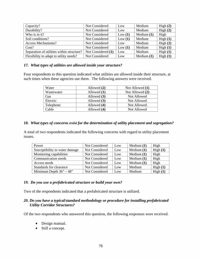
78
Capacity? Not Considered Low Medium High (2) Durability? Not Considered Low Medium High (2) Who is in it? Not Considered Low (1) Medium (1) High Soil conditions? Not Considered Low (1) Medium High (1) Access Mechanisms? Not Considered Low Medium High (2) Cost? Not Considered Low (1) Medium High (1) Separation of utilities within structure? Not Considered (1) Low Medium High (1) Flexibility to adapt to utility needs? Not Considered Low Medium (1) High (1)
17. What types of utilities are allowed inside your structure? Four respondents to this question indicated what utilities are allowed inside their structure, at such times when these agencies use them. The following answers were received.
Water Allowed (2) Not Allowed (1) Wastewater Allowed (1) Not Allowed (2) Gas Allowed (3) Not Allowed Electric Allowed (3) Not Allowed Telephone Allowed (4) Not Allowed Cable Allowed (4) Not Allowed
18. What types of concerns exist for the determination of utility placement and segregation? A total of two respondents indicated the following concerns with regard to utility placement issues.
Power Not Considered Low Medium (1) High Susceptibility to water damage Not Considered Low Medium (1) High (1) Monitoring capabilities Not Considered Low Medium (1) High Communication needs Not Considered Low Medium (1) High Access needs Not Considered Low Medium (1) High Standards for clearance Not Considered Low Medium High (1) Minimum Depth 36” – 48” Not Considered Low Medium High (1)
19. Do you use a prefabricated structure or build your own? Two of the respondents indicated that a prefabricated structure is utilized. 20. Do you have a typical/standard methodology or procedure for installing prefabricated
Utility Corridor Structures? Of the two respondents who answered this question, the following responses were received.
• Design manual. • Still a concept.
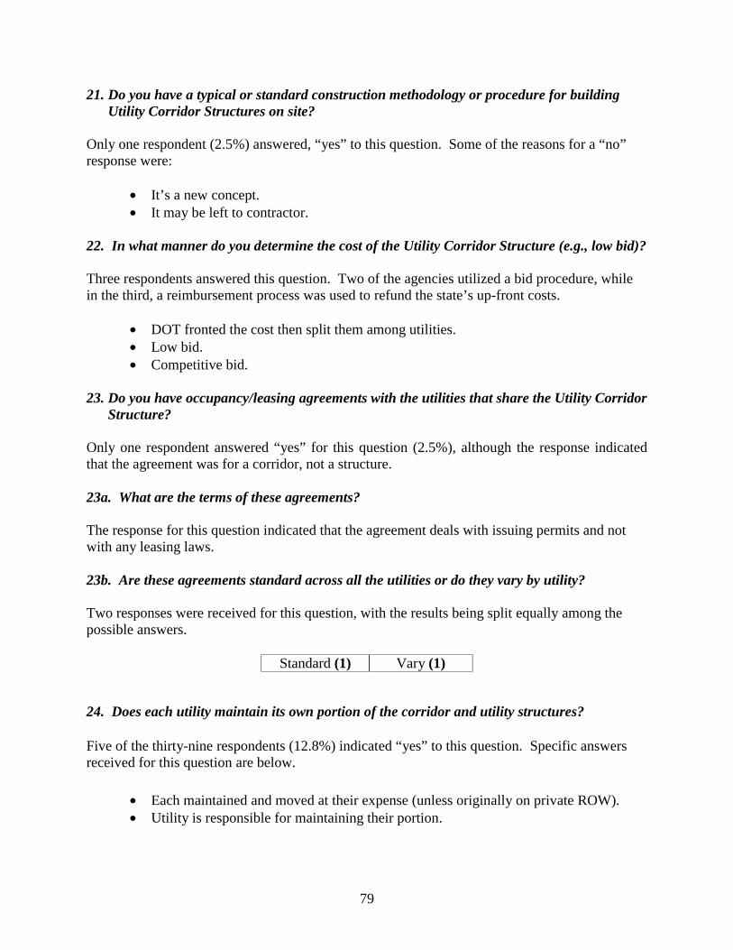
79
21. Do you have a typical or standard construction methodology or procedure for building Utility Corridor Structures on site?
Only one respondent (2.5%) answered, “yes” to this question. Some of the reasons for a “no” response were:
• It’s a new concept. • It may be left to contractor.
22. In what manner do you determine the cost of the Utility Corridor Structure (e.g., low bid)? Three respondents answered this question. Two of the agencies utilized a bid procedure, while in the third, a reimbursement process was used to refund the state’s up-front costs.
• DOT fronted the cost then split them among utilities. • Low bid. • Competitive bid.
23. Do you have occupancy/leasing agreements with the utilities that share the Utility Corridor
Structure? Only one respondent answered “yes” for this question (2.5%), although the response indicated that the agreement was for a corridor, not a structure. 23a. What are the terms of these agreements? The response for this question indicated that the agreement deals with issuing permits and not with any leasing laws. 23b. Are these agreements standard across all the utilities or do they vary by utility? Two responses were received for this question, with the results being split equally among the possible answers.
Standard (1) Vary (1)
24. Does each utility maintain its own portion of the corridor and utility structures?
Five of the thirty-nine respondents (12.8%) indicated “yes” to this question. Specific answers received for this question are below.
• Each maintained and moved at their expense (unless originally on private ROW). • Utility is responsible for maintaining their portion.
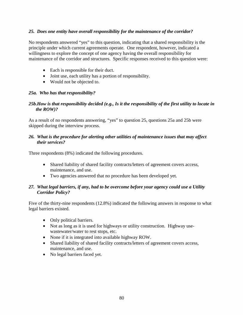
80
25. Does one entity have overall responsibility for the maintenance of the corridor? No respondents answered “yes” to this question, indicating that a shared responsibility is the principle under which current agreements operate. One respondent, however, indicated a willingness to explore the concept of one agency having the overall responsibility for maintenance of the corridor and structures. Specific responses received to this question were:
• Each is responsible for their duct. • Joint use, each utility has a portion of responsibility. • Would not be objected to.
25a. Who has that responsibility? 25b.How is that responsibility decided (e.g., Is it the responsibility of the first utility to locate in
the ROW)? As a result of no respondents answering, “yes” to question 25, questions 25a and 25b were skipped during the interview process. 26. What is the procedure for alerting other utilities of maintenance issues that may affect
their services? Three respondents (8%) indicated the following procedures.
• Shared liability of shared facility contracts/letters of agreement covers access, maintenance, and use.
• Two agencies answered that no procedure has been developed yet. 27. What legal barriers, if any, had to be overcome before your agency could use a Utility
Corridor Policy? Five of the thirty-nine respondents (12.8%) indicated the following answers in response to what legal barriers existed.
• Only political barriers. • Not as long as it is used for highways or utility construction. Highway use-
wastewater/water to rest stops, etc. • None if it is integrated into available highway ROW. • Shared liability of shared facility contracts/letters of agreement covers access,
maintenance, and use. • No legal barriers faced yet.
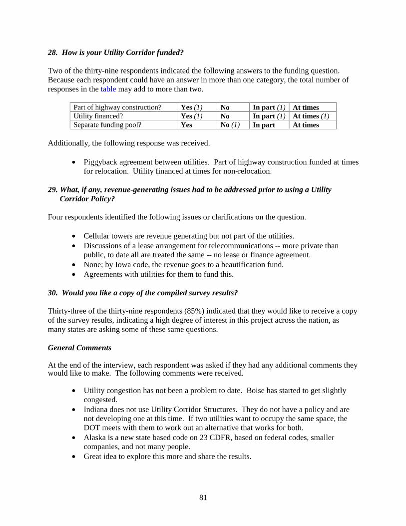
81
28. How is your Utility Corridor funded? Two of the thirty-nine respondents indicated the following answers to the funding question. Because each respondent could have an answer in more than one category, the total number of responses in the table may add to more than two.
Part of highway construction? Yes (1) No In part (1) At times Utility financed? Yes (1) No In part (1) At times (1) Separate funding pool? Yes No (1) In part At times
Additionally, the following response was received.
• Piggyback agreement between utilities. Part of highway construction funded at times for relocation. Utility financed at times for non-relocation.
29. What, if any, revenue-generating issues had to be addressed prior to using a Utility
Corridor Policy? Four respondents identified the following issues or clarifications on the question.
• Cellular towers are revenue generating but not part of the utilities. • Discussions of a lease arrangement for telecommunications -- more private than
public, to date all are treated the same -- no lease or finance agreement. • None; by Iowa code, the revenue goes to a beautification fund. • Agreements with utilities for them to fund this.
30. Would you like a copy of the compiled survey results? Thirty-three of the thirty-nine respondents (85%) indicated that they would like to receive a copy of the survey results, indicating a high degree of interest in this project across the nation, as many states are asking some of these same questions. General Comments At the end of the interview, each respondent was asked if they had any additional comments they would like to make. The following comments were received.
• Utility congestion has not been a problem to date. Boise has started to get slightly
congested. • Indiana does not use Utility Corridor Structures. They do not have a policy and are
not developing one at this time. If two utilities want to occupy the same space, the DOT meets with them to work out an alternative that works for both.
• Alaska is a new state based code on 23 CDFR, based on federal codes, smaller companies, and not many people.
• Great idea to explore this more and share the results.

82
• New Hampshire does not have much to offer in this arena but would be interested in seeing what other states are doing and the success rate.

83
APPENDIX C: STAKEHOLDER TASK FORCE QUESTIONS


85
Stakeholder Questions Question #1: Are there any specific spacing or location requirements that might govern the placement of various utilities within such an enclosed structure? If so, what are they? For example, what spacing might be necessary between a natural gas line and an electricity line? What requirements are there for co-locating electricity and telecommunications lines? Question #2: Consider the following four scenarios in which your utility would potentially participate in a utilidor/utility structure. Note that the circumstances under which TxDOT would use such a facility would be fairly limited, such as in a highly developed urban area along an Interstate or U.S. Highway where a large number of utilities would need to be installed and ROW is at a premium. Participation Optional • Scenario (A): TxDOT would prefer utilities use a longitudinal utility structure within the
TxDOT ROW. A utility company or consortia of companies would pay to install the structure but would NOT have any revenue potential associated with it. However, utilities would NOT be required to install within the structure.
• Scenario (B): TxDOT would prefer utilities use a longitudinal utility structure within the
TxDOT ROW. A utility company or consortia of companies would pay to install the structure but WOULD have revenue potential associated with it (e.g., lead utility could lease space to other utilities). Utilities would NOT be required to install within the structure.
Participation Mandatory • Scenario (C): TxDOT would require utilities use a longitudinal utility structure within the
TxDOT ROW. A utility company or consortia of companies would pay to install the structure but would NOT have any revenue potential associated with it. Utilities choosing to not install within the structure would have to purchase separate ROW for their conduit.
• Scenario (D): TxDOT would require utilities use a longitudinal utility structure within the
TxDOT ROW. A utility company or consortia of companies would pay to install the structure but WOULD have revenue potential associated with it (e.g., lead utility could lease space to other utilities). Utilities choosing to not install within the structure would have to purchase separate ROW for their conduit.
Under which of these scenarios would your utility company consider participating in a utilidor/utility structure and/or considering taking the lead and being the utility to pay for the design, installation, and maintenance of the utility structure? Question #3: If your utility were to take the lead on the design, installation, and maintenance of a utility structure, what inspection and maintenance procedures would you undertake to ensure the safety and functionality of the structure? How frequently would you perform these procedures?
86
Question #4: What does it cost your company/organization to build/install a buried conduit encasing your utility on a linear foot basis, both with and without the purchase of ROW? Question #5: If your utility were to be located within a utility structure, how frequently along the longitudinal length of the structure would you require access for your employees? For example, manholes/access spaced every 500 ft, 1000 ft, ½ mile, 1 mile, other? Question #6: Within a utility structure, how often would you need larger access for equipment or the movement of materials for repair or maintenance of the utility? This would be access larger than a manhole. Question #7: If your utility line within a utility structure is encased, how often would you need to space shut-off valves along the length of the line? Every 500 ft, 1000 ft, ½ mile, 1 mile, other? Question #8: If your utility line were within a utility structure, how would the constrained space impact typical abandonment procedures and would you treat abandonment of such lines differently than traditionally buried conduit? Please note your traditional abandonment procedures in your response. Question #9: If your utility were within a utility structure, what standards would need to be applied to the design of the structure, such as lighting, ventilation, drainage, line identification, etc.? Question #10: What standards or specifications do you follow when installing your utility under a railroad line or crossing? Question #11: Would you need longitudinal access to your lines within a utility structure or would periodic vertical access, as with manholes be sufficient? Question #12: Do you currently have your lines located within multiple casings within the ROW, or are all of your lines within one single conduit? Question #13: Have you ever used multiple casings in the past?

87
APPENDIX D: ISSUES AND CONCERNS OF STAKEHOLDERS

89
Project 0-4149: Feasibility of Utility Corridors
Stakeholder Question Responses - Task 4 Question Number 1: Are there any specific spacing or location requirements that might govern the placement of various utilities within such an enclosed structure? If so, what are they? For example, what spacing might be necessary between a natural gas line and an electricity line? What requirements are there for co-locating electricity and telecommunications lines?
Response Verizon - Regarding power and telecommunication separation, Verizon requires 12" dirt separation in open
trench and conduit run. In enclosed area such as a manhole ( 4x8 ), Verizon would not locate facilities in the same manhole as gas.
TxDOT - Spacing requirements are addressed in 43 Texas Administrative Code Sections 21.31 through 21.56. These rules, often referred to as the UAP (utility accommodation policy), are based upon national standards for safety for both the utilities and the highway facility that they occupy. The rules are not exhaustive, as I am aware that the UAP does not address all spacing requirements/preferences that the utilities may have.
Question Number 2: Consider the following four scenarios in which your utility would potentially participate in a utilidor/utility structure. Note that the circumstances under which TxDOT would use such a facility would be fairly limited, such as in a highly developed urban area along an Interstate or U.S. Highway where a large number of utilities would need to be installed and ROW is at a premium. Under which of these scenarios would your utility company consider participating in a utilidor/utility structure and/or considering taking the lead and being the utility to pay for the design, installation, and maintenance of the utility structure?
Response
Verizon - Overall, Verizon opposes a governmental entity authorizing one provider, or consortia of providers, to build facilities in excess of its needed capacity and consuming the public right of way. This action prohibits, or has the effect of prohibiting, an entity from providing interstate or intrastate telecommunications services, which is contrary to Section 253 of the Federal Telecommunications Act. Depending on how it is structured, such an agreement is also contrary to Section 181.082 of the Texas Utility Code which reads, “A telephone or telegraph corporation may install a facility of the corporation along, on, or across a public road, a public street, or public water in a manner that does not inconvenience the public in the use of the road, street or water.”. Verizon probably has no interest in building such a facility.
Other concerns would include, but are not limited to, security and access to the facility; damage to Verizon’s facilities by other users of the facility and being able to determine who caused the damage; liability due to physical failure of the facility; routine maintenance of the facility including pumping of manholes, etc and how these costs would be allocated among the users of the facility, and order of preference in restoring damage to multiple company facilities. A terrorist attack of such a facility would eliminate telecommunications services for a broad area with one attack.
Scenario A: Verizon would urge TxDOT to consider that allowing one entity, or consortia, to build a facility with excess capacity is consuming right of way that other utilities could use, thus potentially limiting competition. As the builder is prohibited from any revenue potential, there is no incentive for a private entity to build the facilities. Also, the cost of constructing the facility will vary by provider. If it were built, Verizon would only be interested in leasing, or purchasing, space in such a facility if the costs were neutral to the Company as compared to constructing the facilities on its own and if there were adequate safeguards incorporated to protect Verizon’s facilities from damage by other providers located within the system.
Scenario B: The same concerns as above in Scenario A would still be present. The only added incentive is that the entity, or consortia, building the facility will have an opportunity to earn a return on their investment.
Scenario C: Verizon has several concerns with this scenario. In addition to the lack of incentive for a provider, or consortia, to build the facility without a revenue opportunity, the suggestion that providers not using the facility would “have to purchase separate ROW for their conduit” is in direct conflict with Section 181.082 of the Texas Utility Code which reads, “A telephone or telegraph corporation may install a facility of the corporation along, on, or across a public road, a public street, or public water in a manner that does not inconvenience the
90
public in the use of the road, street or water.”. This would likewise be contrary to Section 253 of the Federal Telecommunications Act as it is NOT competitively neutral and creates a barrier to entry into the telecommunications market. A legal challenge is likely under this scenario.
Scenario D: This scenario has the same problems as Scenario C, and only provides a revenue incentive to the builder(s) of the facility.
To build such a facility will require substantial capital resources with possibly no revenue opportunities for a return on the investment as well as an uncertain future market for such facilities. To allow a revenue return will reduce the marketability of such a facility as well as potential legal challenges under federal and/or state laws. There are also numerous operational challenges (security, access, preference for repairs, etc.). Verizon will probably not be interested in building this facility.
Texas Municipal League - In recent years, there has been discussion about shared duct banks between utilities in public rights-of-way, to minimize cuts in streets, but there have not been many success stories, even though it sounds like a good idea. One city that has attempted it is Westlake, in the metroplex area.
Utility companies (especially the telecoms) have a very hard time in sharing their needs (their business plan) with others, in fear of losing any competitive edge. And for anybody to pay for a utility duct bank, they will have to have an idea of potential users in order to regain their investment, and make a profit.
It is pleasing to see that TxDOT is acknowledging that utilities exist in the rights-of-way. Some cities have had experiences that make them believe that TxDOT has the viewpoint that utilities do not belong in ROW at all, and that they should be cleared before any street project begins.
It would be surprising to see TxDOT actually constructing the utility bank as part of a project.
Question Number 4: What does it cost your company/organization to build/install a buried conduit encasing your utility on a linear foot basis, both with and without the purchase of ROW?
Response Verizon - Without the purchase of ROW? Depends on the terrain, range is $40 to $100. With the purchase of ROW? An additional $2 a foot.
Question Number 5: If your utility were to be located within a utility structure, how frequently along the longitudinal length of the structure would you require access for your employees? For example, manholes/access spaced every 500 ft, 1000 ft, ½ mile, 1 mile, other?
Response Verizon - Of course this depends on the size of our facility. On large cable runs we would need to set access at 500' to 750'. Maximum access to our facilities would be 2000’. We have to bond and ground every 2000’.
Question Number 6: Within a utility structure, how often would you need larger access for equipment or the movement of materials for repair or maintenance of the utility? This would be access larger than a manhole.
Response Verizon - Only if foreign party damaged existing facilities in the corridor and maintenance was required to repair.
Question Number 8: If your utility line were within a utility structure, how would the constrained space impact typical abandonment procedures and would you treat abandonment of such lines differently than traditionally buried conduit? Please note your traditional abandonment procedures in your response.
Response Verizon - Our process would be to have rights to two conduits minimum. This would allow for our traditional procedure to be used, where if existing facilities were exhausted or needed replacing for repair Verizon would place appropriate size new facilities in vacant conduit that would allow existing facilities to be removed from conduit so once again Verizon would have a spare conduit.
91
Question Number 10: What standards or specifications do you follow when installing your utility under a railroad line or crossing?
Response Verizon - We place our conduit in a steel pipe (casing) and extend this pipe across the railroad row. We try to keep a min. depth of 60 ft, on aerial crossings we maintain a 27 ft clearance.
Verizon submits a permit to the appropriate railroad office for approval. Requirements vary but, as a rule normally utility companies are required to be 5 ft below ditch grade with bore and place steel casing under track. Aerial crossing usually requires 22 ft to 25 ft of clearance.
Question Number 11: Would you need longitudinal access to your lines within a utility structure or would periodic vertical access, as with manholes be sufficient?
Response Verizon - Periodic access vertically will be sufficient.
Question Number 12: Do you currently have your lines located within multiple casings within the ROW, or are all of your lines within one single conduit?
Response Verizon - Multiple casings and or multiple direct buried lines.
Question Number 13: Have you ever used multiple casings in the past?
Response Verizon - Yes, all of Verizon’s conduit systems are multiple ducts.


93
APPENDIX E: RECOMMENDED CHANGES TO THE TEXAS STATUTES TO FACILITATE THE USE OF UTILITY CORRIDORS BY
TXDOT (FHWA/TX-02/4149-P3)

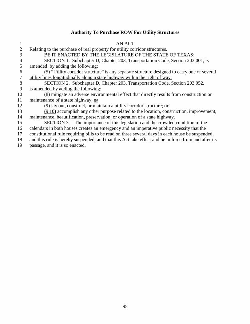
95
Authority To Purchase ROW For Utility Structures
AN ACT 1 Relating to the purchase of real property for utility corridor structures. 2 BE IT ENACTED BY THE LEGISLATURE OF THE STATE OF TEXAS: 3 SECTION 1. Subchapter D, Chapter 203, Transportation Code, Section 203.001, is 4 amended by adding the following: 5 (5) “Utility corridor structure” is any separate structure designed to carry one or several 6 utility lines longitudinally along a state highway within the right of way. 7
SECTION 2. Subchapter D, Chapter 203, Transportation Code, Section 203.052, 8 is amended by adding the following: 9
(8) mitigate an adverse environmental effect that directly results from construction or 10 maintenance of a state highway; or 11
(9) lay out, construct, or maintain a utility corridor structure; or 12 (9 10) accomplish any other purpose related to the location, construction, improvement, 13
maintenance, beautification, preservation, or operation of a state highway. 14 SECTION 3. The importance of this legislation and the crowded condition of the 15
calendars in both houses creates an emergency and an imperative public necessity that the 16 constitutional rule requiring bills to be read on three several days in each house be suspended, 17 and this rule is hereby suspended, and that this Act take effect and be in force from and after its 18 passage, and it is so enacted. 19
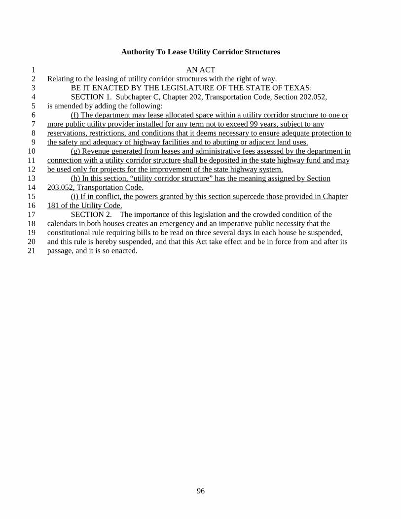
96
Authority To Lease Utility Corridor Structures
AN ACT 1 Relating to the leasing of utility corridor structures with the right of way. 2 BE IT ENACTED BY THE LEGISLATURE OF THE STATE OF TEXAS: 3 SECTION 1. Subchapter C, Chapter 202, Transportation Code, Section 202.052, 4 is amended by adding the following: 5
(f) The department may lease allocated space within a utility corridor structure to one or 6 more public utility provider installed for any term not to exceed 99 years, subject to any 7 reservations, restrictions, and conditions that it deems necessary to ensure adequate protection to 8 the safety and adequacy of highway facilities and to abutting or adjacent land uses. 9
(g) Revenue generated from leases and administrative fees assessed by the department in 10 connection with a utility corridor structure shall be deposited in the state highway fund and may 11 be used only for projects for the improvement of the state highway system. 12
(h) In this section, “utility corridor structure” has the meaning assigned by Section 13 203.052, Transportation Code. 14
(i) If in conflict, the powers granted by this section supercede those provided in Chapter 15 181 of the Utility Code. 16
SECTION 2. The importance of this legislation and the crowded condition of the 17 calendars in both houses creates an emergency and an imperative public necessity that the 18 constitutional rule requiring bills to be read on three several days in each house be suspended, 19 and this rule is hereby suspended, and that this Act take effect and be in force from and after its 20 passage, and it is so enacted. 21

97
APPENDIX F: RECOMMENDED CHANGES TO THE TEXAS ADMINISTRATIVE CODE TO FACILITATE THE USE OF UTILITY
CORRIDORS BY TXDOT (FHWA/TX-02/4149-P3)

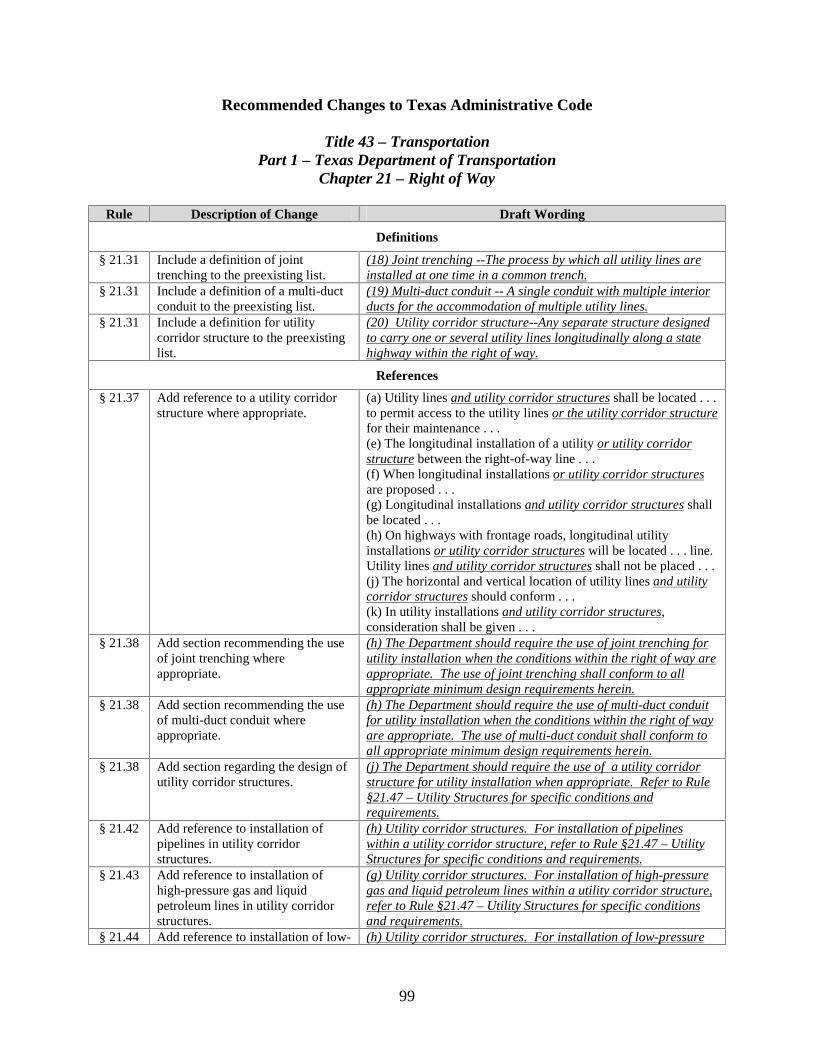
99
Recommended Changes to Texas Administrative Code
Title 43 – Transportation Part 1 – Texas Department of Transportation
Chapter 21 – Right of Way
Rule Description of Change Draft Wording
Definitions
§ 21.31 Include a definition of joint trenching to the preexisting list.
(18) Joint trenching --The process by which all utility lines are installed at one time in a common trench.
§ 21.31 Include a definition of a multi-duct conduit to the preexisting list.
(19) Multi-duct conduit -- A single conduit with multiple interior ducts for the accommodation of multiple utility lines.
§ 21.31 Include a definition for utility corridor structure to the preexisting list.
(20) Utility corridor structure--Any separate structure designed to carry one or several utility lines longitudinally along a state highway within the right of way.
References
§ 21.37 Add reference to a utility corridor structure where appropriate.
(a) Utility lines and utility corridor structures shall be located . . . to permit access to the utility lines or the utility corridor structure for their maintenance . . . (e) The longitudinal installation of a utility or utility corridor structure between the right-of-way line . . . (f) When longitudinal installations or utility corridor structures are proposed . . . (g) Longitudinal installations and utility corridor structures shall be located . . . (h) On highways with frontage roads, longitudinal utility installations or utility corridor structures will be located . . . line. Utility lines and utility corridor structures shall not be placed . . . (j) The horizontal and vertical location of utility lines and utility corridor structures should conform . . . (k) In utility installations and utility corridor structures, consideration shall be given . . .
§ 21.38 Add section recommending the use of joint trenching where appropriate.
(h) The Department should require the use of joint trenching for utility installation when the conditions within the right of way are appropriate. The use of joint trenching shall conform to all appropriate minimum design requirements herein.
§ 21.38 Add section recommending the use of multi-duct conduit where appropriate.
(h) The Department should require the use of multi-duct conduit for utility installation when the conditions within the right of way are appropriate. The use of multi-duct conduit shall conform to all appropriate minimum design requirements herein.
§ 21.38 Add section regarding the design of utility corridor structures.
(j) The Department should require the use of a utility corridor structure for utility installation when appropriate. Refer to Rule §21.47 – Utility Structures for specific conditions and requirements.
§ 21.42 Add reference to installation of pipelines in utility corridor structures.
(h) Utility corridor structures. For installation of pipelines within a utility corridor structure, refer to Rule §21.47 – Utility Structures for specific conditions and requirements.
§ 21.43 Add reference to installation of high-pressure gas and liquid petroleum lines in utility corridor structures.
(g) Utility corridor structures. For installation of high-pressure gas and liquid petroleum lines within a utility corridor structure, refer to Rule §21.47 – Utility Structures for specific conditions and requirements.
§ 21.44 Add reference to installation of low- (h) Utility corridor structures. For installation of low-pressure
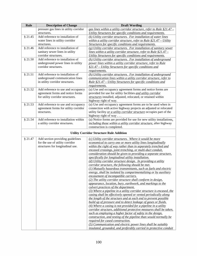
100
Rule Description of Change Draft Wording pressure gas lines in utility corridor structures.
gas lines within a utility corridor structure, refer to Rule §21.47 – Utility Structures for specific conditions and requirements.
§ 21.45 Add reference to installation of water lines in utility corridor structures.
(k) Utility corridor structures. For installation of water lines within a utility corridor structure, refer to Rule §21.47 – Utility Structures for specific conditions and requirements.
§ 21.46 Add reference to installation of sanitary sewer lines in utility corridor structures.
(g) Utility corridor structures. For installation of sanitary sewer lines within a utility corridor structure, refer to Rule §21.47 – Utility Structures for specific conditions and requirements.
§ 21.50 Add reference to installation of underground power lines in utility corridor structures.
(h) Utility corridor structures. For installation of underground power lines within a utility corridor structure, refer to Rule §21.47 – Utility Structures for specific conditions and requirements.
§ 21.51 Add reference to installation of underground communication lines in utility corridor structures.
(h) Utility corridor structures. For installation of underground communication lines within a utility corridor structure, refer to Rule §21.47 – Utility Structures for specific conditions and requirements.
§ 21.52 Add reference to use and occupancy agreement forms and notice forms for utility corridor structures.
(a) Use and occupancy agreement forms and notice forms are provided for use for utility facilities and utility corridor structures installed, adjusted, relocated, or retained within highway right of way.
§ 21.53 Add reference to use and occupancy agreement forms for utility corridor structures.
(a) Use and occupancy agreement forms are to be used when in connection with active highway projects an adjusted or relocated utility facility or a utility corridor structure occupies part of the highway right of way . . .
§ 21.54 Add reference to installation within a utility corridor structures.
(a) Notice forms are provided for use for new utility installations, including those within a utility corridor structure, after highway construction is completed.
Utility Corridor Structure Rule Addition
§ 21.47 Add section providing guidelines for the use of utility corridor structures for longitudinal use.
(c) Utility corridor structures. Where it would be more economical to carry one or more utility lines longitudinally within the right of way rather than in separately trenched and encased crossings, joint trenching, or multi-duct conduit, consideration should be given to providing a separate structure, specifically for longitudinal utility installation. (d) Utility corridor structure design. In providing a utility corridor structure, the following should be met. (1) Mutually hazardous transmittants, such as fuels and electric energy, shall be isolated by compartmentalizing or by auxiliary encasement of incompatible carriers. (2) The utility corridor structure shall conform in design, appearance, location, bury, earthwork, and markings to the culvert practices of the department. (3) Where a pipeline in a utility corridor structure is encased, the casing shall be effectively opened or vented periodically along the length of the structure and at each end to prevent possible build up of pressure and to detect leakage of gases or fluids. (4) Where a casing is not provided for a pipeline in a utility corridor structure, additional protective measures shall be taken, such as employing a higher factor of safety in the design, construction, and testing of the pipeline than would normally be required for cased construction. (5) Communication and electric power lines shall be suitably insulated, grounded, and preferably carried in protective conduit
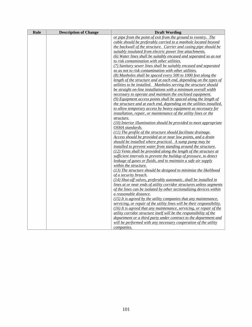
101
Rule Description of Change Draft Wording or pipe from the point of exit from the ground to reentry. The cable should be preferably carried to a manhole located beyond the backwall of the structure. Carrier and casing pipe should be suitably insulated from electric power line attachments. (6) Water lines shall be suitably encased and separated so as not to risk contamination with other utilities. (7) Sanitary sewer lines shall be suitably encased and separated so as not to risk contamination with other utilities. (8) Manholes shall be spaced every 500 to 1000 feet along the length of the structure and at each end, depending on the types of utilities to be installed. Manholes serving the structure should be straight on-line installations with a minimum overall width necessary to operate and maintain the enclosed equipment. (9) Equipment access points shall be spaced along the length of the structure and at each end, depending on the utilities installed, to allow temporary access by heavy equipment as necessary for installation, repair, or maintenance of the utility lines or the structure. (10) Interior illumination should be provided to meet appropriate OSHA standards. (11) The profile of the structure should facilitate drainage. Access should be provided at or near low points, and a drain should be installed where practical. A sump pump may be installed to prevent water from standing around the structure. (12) Vents shall be provided along the length of the structure at sufficient intervals to prevent the buildup of pressure, to detect leakage of gases or fluids, and to maintain a safe air supply within the structure. (13) The structure should be designed to minimize the likelihood of a security breach. (14) Shut-off valves, preferably automatic, shall be installed in lines at or near ends of utility corridor structures unless segments of the lines can be isolated by other sectionalizing devices within a reasonable distance. (15) It is agreed by the utility companies that any maintenance, servicing, or repair of the utility lines will be their responsibility. (16) It is agreed that any maintenance, servicing, or repair of the utility corridor structure itself will be the responsibility of the department or a third party under contract to the department and will be performed with any necessary cooperation of the utility companies.

103
APPENDIX G: DRAFT OCCUPANCY AGREEMENT GOVERNING INSTALLATION OF PUBLIC UTILITIES IN UTILITY CORRIDOR
STRUCTURES IN TXDOT ROW (FHWA/TX-02/4149-P2)

Draft Occupancy Agreement for Utility Corridor Structure
105
UTILITY CORRIDOR STRUCTURE OCCUPANCY AGREEMENT CONTROLLED ACCESS HIGHWAY
Agreement No.
County: ROW CSJ No.: Federal Project No.: Highway No.: Contract No.: Limits From: To: WHEREAS, the State of Texas, hereinafter called the State, acting by and through the Texas Department of Transportation, hereinafter called the Department, proposes to make certain highway improvements on that section of the above-indicated highway; and WHEREAS, the Department requires the use of a Utility Corridor Structure for the accommodation of utilities within the right of way on all or part of that section of the above-indicated highway; and WHEREAS, the , hereinafter called the Owner, proposes to retain, locate, or relocate certain of its facilities as indicated on the plans attached to the Standard Utility Agreement as executed by Owner on the day of , , or on location sketches attached hereto, except as provided herein below; NOW THEREFORE, it is hereby mutually agreed: 1. DEFINITIONS 1.1 In this Agreement, the following words and phrases shall have the following meanings:
(a) “Affiliate” shall mean any person, partner, company, or organization having,
directly or indirectly, an interest in or a joint venture with the Utility, including, without limitation, a parent company;
(b) “Agency” means any governmental agency or quasi-governmental agency other
than the State; (c) “Agreement” means this instrument; (d) “American Association of State Highway and Transportation Officials
(AASHTO)” is an association of state highway and transportation officials;
(e) “Approval,” “Approve,” or “Approved,” when used with referent to the Department approval, mean the prior written approval of the District Engineer unless another person or method for approval is specified herein or under applicable Law. When used in reference to any Agency, they mean the final approval of that Agency as provided under applicable Law;
Draft Occupancy Agreement for Utility Corridor Structure
106
(f) “Boundaries” means the existing boundaries of the State of Texas;
(g) “Business Day” means any day that is not Saturday, Sunday, or an official State
holiday;
(h) “Clear Roadside Policy” means a policy to increase safety, improve traffic operation, and enhance the appearance of highways by designing, constructing, and maintaining highway roadsides as wide, flat, and rounded as practical and as free as practical from physical obstructions above the ground and travelway such as trees, drainage structures, massive sign supports, utility poles, and other ground-mounted obstructions;
(i) “Commission” means the Texas Transportation Commission with the
responsibilities for transportation services within the State;
(j) “Contractors” means contractors, subcontractors, workers, suppliers, and material persons;
(k) “Controlled Access Roadway” means a highway on which owners or occupants
of abutting lands and other persons are denied access to or from the highway except as authorized by the Department;
(l) “Customer” means any Person who uses the Utility services within the
Boundaries of the State;
(m) “Department” means the Texas Department of Transportation;
(n) “District Engineer” means the chief administrative officer in charge of one of the 25 districts of the Department;
(o) “Effective Date” means thirty (30) days from and after the execution of this
Agreement;
(p) “Employee” means
(1) with respect to the Utility, any official, officer, employee, Contractor, or authorized agent of the Utility;
(2) with respect to the Department, any official, officer, employee, authorized
agent or Contractor of the Department but specifically excludes the Utility and any Employee of the Utility; and
(3) with respect to the Contractors of the Department or Utility, any officer,
employee or agent of the Contractors;
Draft Occupancy Agreement for Utility Corridor Structure
107
(q) “Executive Director” means the Executive Director of the Texas Department of Transportation;
(r) “Facilities” means utilities; (s) “Frontage Roads” means a street or road auxiliary to, and located on the side of,
an expressway or freeway that segregates local traffic from high-speed through traffic and provides service to abutting property and control of access;
(t) “Hazardous Material” includes, but is not limited to, any substance, waste, or
material which, because of its quantity, concentration, or physical or chemical characteristics is deemed by any federal, state, or local governmental authority to pose a present or potential hazard to human health or safety or to the environment;
(u) “Law” or “Laws” mean any judicial decision, statute, constitution, ordinance,
resolution, regulation, rule, tariff, administrative order, certificate, order, or other requirement of the State, the Department, or any other Agency having joint or several jurisdiction over the subject matter of this Agreement, in effect either at the time of execution of this Agreement or at any time during the period Utilities are located in highway rights-of-way, including, without limitation, any regulation or order of an official entity or body;
(v) “Person” means any individual, Corporation, partnership, association, joint
venture, or organization of any kind and the lawful trustee, successor, assignee, transferee, or personal representative;
(w) “Right of Way” means the area in, on, upon, above, beneath, within, along,
across, under, or over the dedicated public streets, sidewalks, roads, lanes, courts, ways, alleys, boulevards, and places that are owned and operated by the State, as they now or hereafter exist and which are under the permitting jurisdiction of the Department;
(x) “Release” when used with respect to Hazardous Material means any actual or
imminent spilling, leaking, pumping, pouring, emitting, emptying, discharging, injecting, escaping, leaching, dumping, or disposing into or inside any existing improvements or improvements constructed hereunder by or on behalf of the Owner, or in, under or about the public Right of Way;
(y) “State” means the State of Texas;
(z) “Third Party” means any individual, Corporation, partnership, association, joint
venture, or organization of any kind and the lawful trustee, successor, assignee, transferee, or personal representative thereof that attaches to the Owner under an agreement with the Owner;

Draft Occupancy Agreement for Utility Corridor Structure
108
(aa) “Utilities” includes, but is not limited to, all lines and/or their accessories or tangible things owned, leased, operated, or licensed by the Utility, located or to be located within the highway Rights-of-Way, and used or useful for and in connection with the rendering of utility services by the Utility lawfully or unlawfully installed within the Boundaries of the State, except those for highway-oriented needs. Such utilities may involve underground, surface, or overhead facilities either singularly or in combination. Accessories are any attachments, appurtenances, or integral parts of the utility (i.e., fire hydrants, valves, gas regulators, etc.). The placing of accessories within the highway rights of way will be determined by such factors as type, size, safety, availability of space, etc;
(bb) “Utility Corridor Structure” means any separate structure designed to carry one
or several utility lines longitudinally along a state highway within the Right of Way; and
(cc) “Work” means any installation or other alteration of Utilities in, on, under, over,
along, or across the Right of Way. 2. TERM 2.1 This Agreement shall commence upon the date of execution and shall be ongoing unless
either the Department or the Owner gives written notice of cancellation to the other not less than thirty (30) days prior to the desired expiration of this Agreement at which time this Agreement shall terminate and on the day so names in such notice this Agreement and all rights and privileges thereunder shall come to an end.
2.2 Notwithstanding the expiry or termination of this Agreement, the liabilities and
obligations of the Owner, its contractors, and agents under this Agreement, including all fees and payments shall continue and remain in full force and effect with respect to the Utility Corridor Structure used by the Owner until all the Owner’s Facilities are removed from the Utility Corridor Structure.
3. LIMITATIONS AND RESTRICTIONS 3.1 Subject to the provisions of this Agreement, the Department hereby grants to the Owner a
non-exclusive license to construct, install, maintain, locate, move, occupy, operate, place, protect, reconstruct, reinstall, relocate, remove, and replace Facilities underground within the Utility Corridor Structure within the highway Right-of-Way limits as such area is defined and to the extent indicated on aforementioned plans for the sole purpose of providing services to its customers. Any work performed by the Owner shall be conditioned upon the Owner obtaining all other permits and Approvals that may be required by the Department or any Agency. Nothing in this Agreement is intended to imply that the Department or any Agency will issue such permits or Approvals.
3.2 The Owner represents, warrants, and covenants that its Facilities will be utilized for the
sole purpose of providing services by the Owner to the Owner’s customers. Use of the
Draft Occupancy Agreement for Utility Corridor Structure
109
Facilities for any additional purpose shall constitute a violation of the material conditions of this Agreement.
3.3 The Department reserves any and all authority it may have not or in the future to regulate
or otherwise condition the Facilities, their use, or the use of the Right of Way or Department’s property.
3.4 Notwithstanding any other provision of this Agreement, all activities conducted pursuant
hereto shall be conducted at the Owner’s sole cost and expense. 3.5 Nothing in this Agreement, nor any use hereunder, shall be deemed to grant, convey,
create, or vest in the Owner a real property interest in any portion of the Right of Way or Department property, including, but not limited to, any fee or leasehold interest in land, easement, or franchise.
3.6 Notwithstanding any other provision of this Agreement, any and all rights expressly or
impliedly granted to the Owner under this Agreement shall be subject and subordinant to the continuing right of the Department to use any and all parts of the Right of Way exclusively or concurrently with any other Person or Persons, and further subject to the public easement for streets and any and all other deeds, easements, dedications, conditions, covenants, restrictions, encumbrances, franchises, and claims of title which may affect the Right of Way.
4. APPLICATION OF LAWS 4.1 Owner agrees that all work performed in the Right of Way by it or its agents, including
work not involving excavation, shall be performed in compliance with this Agreement, any other permits or Approvals issued hereto, and with all federal, state, and local requirements, including, but not limited to, the Texas Utility Accommodation Policy, as amended. The Owner shall, at its sole expense, procure and maintain in force at all times during its use of the Right of Way any and all business and other licenses or Approvals necessary to conduct the activities allowed hereunder. If required by applicable Laws, the Owner shall obtain the Approval of the Department, or Agency, and obtain Approval of the impact that the Facilities may have upon the environment. Nothing in this Agreement is intended to imply that the Department will issue such Approvals.
4.2 The Owner shall be solely responsible for the payment of all lawful fees, bonds, and
depositions required by any Agency as required by Law charged in connection with the exercise of the Owner’s right, title, and interest in, and the construction, installation, maintenance, and operation of, the Facilities and the rendering of services under this Agreement.
5. PROVISION OF UTILITY CORRIDOR STRUCTURE 5.1 The Department and the Owner agree that the Department or its Contractor shall design,
construct, install, maintain, repair, protect, and remove the Utility Corridor Structure and
Draft Occupancy Agreement for Utility Corridor Structure
110
its components, exclusive of the Facilities, within the highway Right-of-Way limits as such area is defined and to the extent indicated on aforementioned plans for the sole purpose of accommodating one or more Owner.
5.2 If at any time the Utility Corridor Structure is breached or suffers damage, the
Department and the State agree to cooperate in repair the structure and the Facilities damaged as a result of that breach pursuant to subsection 7 of this Agreement.
6. APPROVAL OF LOCATION AND INSTALLATION 6.1 At the time that the Department determines the installation of a Utility Corridor Structure
is required within the highway Right-of-Way limits as such area is defined, the Owner agrees to work with the Department to identify the Owner’s space needs within the Structure.
6.2 The Owner shall not install any of its Facilities within the Utility Corridor Structure
without providing to the Department complete drawings and other materials as are reasonably required by the Department setting out the location and method of construction of the Facilities within the Utility Corridor Structure and obtaining written Approval of the Department with regard to the proposed location of and pursuant to any Law governing the placement of the Facilities within a Utility Corridor Structure.
6.3 The Owner undertakes and agrees with the Department, that it shall, at the request of the
District Engineer, from time to time, submit such information as may reasonably be required by the District Engineer for the purpose of joint utility coordination between the Owner and other users of the Utility Corridor Structure, to indicate the scope of planned work contemplated by the Owner. The Department agrees that it shall, at the reasonable request of the Owner, provide information to the Owner on its planned work activities within the Utility Corridor Structure.
6.4 The Owner shall provide to the Department a report listing the Facilities installed by it, or
on its behalf, in the Utility Corridor Structure within thirty (30) days of any facility alteration.
7. JOINT RESPONSE TEAM PARTICIPATION 7.1 The Department and the Owner agree to form and to actively participate in a Joint
Response Team that has as its responsibility to coordinate the safe and efficient repair of a breach or damage to a Utility Corridor Structure. The responsibilities of the Joint Response Team include, but are not limited to, the following:
(a) Determine which Owners have Facilities in the Utility Corridor Structure; (b) Contact all Owners with Facilities in the Utility Corridor Structure after receiving a
damage report; (c) Designate a contact person with a backup for each Owner; (d) Establish a safe work perimeter;
Draft Occupancy Agreement for Utility Corridor Structure
111
(e) Take appropriate precautions to eliminate ignition sources; (f) Shut off any natural gas Facilities impacted by the breach or damage; (g) Assess the damages to the Utility Corridor Structure; (h) Repair any natural gas Facilities and electrical Facilities first followed by
telecommunications and other Facilities by order of priority; (i) Complete an as-built record of repairs with each utility; (j) Repair the damage to the Utility Corridor Structure; (k) Complete an as-built record of the Utility Corridor Structure; (l) Set up a training course on emergency response as appropriate.
7.2 The Department and the Owner shall agree to identify a lead coordinator for the Joint
Response Team whose responsibility will be to lead the report of the Utility Corridor Structure with the cooperation of all parties.
8. REMOVAL AND RELOCATION OF FACILITIES 8.1 The Department reserves the right to occupy the Right of Way, or any part thereof, which
is occupied or to be occupied by the Utility Corridor Structure. In the event that the existence of Utility Corridor Structure is or will be detrimental to the Department’s use of the Right of Way, as reasonably determined by the District Engineer, the Department shall at its own cost and expense temporarily or permanently remove or relocate the Utility Corridor Structure. In such cases, the Owner shall at its own cost and expense temporarily or permanently remove or relocate its Facilities within the relocated Utility Corridor Structure. The Department will not unreasonably withhold Approval of any plan for removal or relocation of the Facilities. Such removal or relocation shall be completed within the time prescribed by the District Engineer. If the Facilities are not removed or relocated as prescribed by the District Engineer and within the prescribed time, the Department may take all reasonable, necessary, and appropriate action, including removing the Facilities, and shall charge the reasonable costs actually incurred, including but not limited to administrative costs, to the Owner.
8.2 The Owner may notify the Department, or the Department may determine, that the
Facilities within the Utility Corridor Structure or any part thereof, are abandoned or no longer used or useful by the Owner in providing service. At the Department’s request, the Owner shall promptly provide information to the Department, describing in detail the location of such Facilities. At the Department’s sole option, the Owner shall convey such Facilities to the Department at no cost or remove the Facilities from the Utility Corridor Structure. If the Owner fails to remove the Facilities from the Utility Corridor Structure, the Department shall be entitled to costs actually incurred, including but not limited to administrative costs, to the Owner. Upon the Department’s demand, the Owner shall execute such documents of title as will convey all right, title, and interest in the abandoned Facilities, or any part thereof, to the Department free and clear of liens and/or adverse claims of title.
8.3 Whenever the removal or relocation of the Facilities within a Utility Corridor Structure is
required under the Agreement, the Owner shall, after the removal or relocation of the
Draft Occupancy Agreement for Utility Corridor Structure
112
Facilities, at its own cost and expense, promptly repair, restore, and return the Utility Corridor Structure to a safe and satisfactory condition, as Approved by the District Engineer in accordance with applicable Laws and standard requirements. If the Owner does not return the affected Structure to a safe and satisfactory condition, the Department shall have the option to perform or cause to be performed such reasonable and necessary work on behalf of the Owner and charge the actual costs incurred, including but not limited to administrative costs, to the Owner. Upon the receipt of a demand for payment by the Department, the Owner shall reimburse the Department for such costs.
9. WORK PERMIT(S) 9.1 Prior to commencing any work in the Utility Corridor Structure, the Owner shall apply
for and obtain work permits and all other required regulatory permits in accordance with the Laws then in effect, for each construction project or other activity to be performed with the Utility Corridor Structure within the Right of Way, unless such project or activity is necessary on an emergency basis. If an emergency situation occurs and the usual means of access for service operations as herein provided will not permit the immediate action required by the Owner in making emergency repairs as required for the safety and welfare of the public, the Owner shall have temporary right of access to and from the through-traffic roadways and ramp as necessary to accomplish the required emergency repairs. The Owner shall provide the District Engineer with at least ten (10) days notice prior to performing any maintenance and/or new installations in the Utility Corridor Structure. The Owner shall provide the District Engineer with accurate and complete plans reflecting any installation of new facilities or removal of old facilities within thirty (30) days of the completion of the work.
9.2 The Owner shall maintain current, accurate, and complete plans and record drawings
showing, in detail, the exact location, depth, and size of any Facilities constructed or installed within the Utility Corridor Structure in the Right of Way in relation to other facilities in the Utility Corridor Structure. Upon demand, such plans and record drawings shall be delivered to the Department in a form to be determined by the District Engineer.
10. LIABILITY, INDEMNIFICATION, DEPOSITS, AND INSURANCE 10.1 The Department requires complete liability, indemnification, and insurance provisions by
the Owner for all work performed and facilities placed within the Utility Corridor Structure.
10.2 The Owner’s compliance with the provisions in this Section shall in no way relieve or
decrease the Owner’s indemnification obligations under the Agreement or any of the Owner’s other obligations hereunder. Notwithstanding anything to the contrary in this Agreement, this Agreement shall terminate immediately, without notice to the Owner, upon the lapse of any required insurance coverage. The Owner shall be responsible, at its expense, for separately insuring the Owner’s personal property.
Draft Occupancy Agreement for Utility Corridor Structure
113
11. PENALTIES 11.1 The Owner understands and agrees that it may be liable for civil and/or criminal penalties
for failure to comply with any of the terms and conditions of this Agreement or any federal, state, or local Laws.
11.2 All remedies prescribed in this Agreement shall be cumulative, and the use of one or
more remedies by the Department shall not bar the use of any other remedy, including any remedy provided by the other Code or Law, for the purpose of enforcing the provisions of the Agreement. Nothing in this Agreement limits the Department’s authority to revoke any work permit issued to the Owner based on any violation by the Owner of the terms and conditions of such work permit or this Agreement.
12. LEGISLATIVE CHANGE 12.1 If at any time subsequent to the parties entering into this Agreement:
(a) the state or federal government or a regulatory authority, acting within its jurisdiction, enacts or repeals any legislation or regulation, or orders, or directs, or mandates anything which pertains to the Owner’s use of the Utility Corridor Structure or to the subject matter of this Agreement; or
(b) there is rendered any decision of a court of final appeal which pertains to the Owner’s
use of the Utility Corridor Structure or to the subject matter of this Agreement; then either party may notify the other of its intention to require the other party to enter into good faith negotiations to amend this Agreement or to enter into a new agreement reflecting such legislative or regulatory action or court decision, as the case may be, within thirty (30) days after written notice (the “Notice”) from the notifying party.
13.2 If the parties are unable to renegotiate the terms and conditions of this Agreement under
Section 15.1, then the unresolved matters may, within thirty (30) days prior written notice from the requesting party, be referred by the party to arbitration for resolution, in accordance with Section 17 of this Agreement. Subject to the right to request arbitration, if an amendment or new agreement is not reached within ninety (90) days from the date on which Notice was received, either party may terminate this Agreement without further notice and both parties shall fulfill their respective obligations thereafter in accordance with this Agreement.
13. TERMINATION 14.1 This Agreement shall be terminated if either the Department or the Owner violates the
material conditions of this Agreement or by mutual agreement of both parties.
Draft Occupancy Agreement for Utility Corridor Structure
114
14. MISCELLANEOUS PROVISIONS 14.1 This Agreement shall not be amended except by written agreement executed by both the
Department and the Owner. 15. NOTICE 15.1 All notices which shall or may be given pursuant to this Agreement shall be in writing
and transmitted through the United States mail, by means of private delivery systems, or by facsimile transmission, if a hard copy of the same is followed by delivery through the United States mail or by private delivery systems as follows:
DEPARTMENT: Texas Department of Transportation Attn: Copy: Attn: OWNER: Attn: Copy: Attn:
IN WITNESS WHEREOF, the parties hereto have affixed their signatures. Owner: EXECUTION RECOMMENDED: Utility Name
By: Authorized Signature District Engineer, Texas Department of Transportation District
Title: Date:
THE STATE OF TEXAS Certified as being executed for the purpose and effect of activating and/or carrying out the orders, established policies or work programs heretofore approved and authorized by the Texas Transportation Commission under Minute Order No.: ___________.
By: Director, Right of Way Division
Date:
115
APPENDIX H: DRAFT SPECIFICATION/STANDARD FOR UTILITY ACCOMMODATION ALTERNATIVES IN TXDOT ROW
(FHWA/TX-02/4149-P1)

Draft Specification for Utility Corridor Structure
117
ITEM XXX
SPECIFICATIONS FOR UTILITY ACCOMMODATION ALTERNATIVES
IN TXDOT ROW
JOINT TRENCHING
The minimum separation described by codes, ordinances, and utility owner policies must be
maintained. Minimum depths must meet policies of TxDOT and must comply with codes,
ordinances, and/or utility owner policies. Underground detectable warning tape shall be placed in
all trenches at 1 ft below finished grade.
MULTIPLE DUCT CONDUITS
The compatibility of utilities must be determined for placement within a multiple duct. Multiple-
duct conduits shall be installed in accordance with TxDOT Specifications for culverts and in
accordance with the manufacturer’s specifications.
UTILITY CORRIDOR STRUCTURES Utility corridor structures must meet the requirements of ITEM 462: CONCRETE BOX
CULVERTS AND STORM DRAINS. Additionally, the following design considerations should
be met, depending upon TxDOT requirements:
• The structural design shall be based on the size of the corridor.
• A sump pump may be needed to prevent water from standing around the duct.
• The profile of the structure should facilitate drainage. Access should be provided at or
near low points, and a drain should be installed where practical.
• Hangers and or shelves should be designed and spaced based upon the type of utility line
to be supported. Flexible lines may require a full-length shelf for support.
• The structures should be waterproofed as per TxDOT specifications.
Draft Specification for Utility Corridor Structure
118
Utility corridor structures may be designed as:
• Case I: large structures that provide a corridor as a walkway throughout the facility, or
• Case II: smaller structures without a walkway and with accessibility provided at
designated intervals by removal of the deck.
Additional Case I considerations include:
• Case I structures may be corrugated metal pipe (60 to 90 in.) or a concrete box culvert,
pre-cast or cast in place as per TxDOT specifications, with a minimum height of 6 ft, 0
in. and a desirable height of 6 ft, 5 in.
• The aisle width for Case I structures should be 30 in. at a minimum and, desirably, should
be 36 in.
• Case I structures should provide access points at 500- to 1000-ft intervals, depending
upon the types of utilities to be installed.
Additional Case II considerations include:
• Case II structures shall be designed so they can be access through a structure deck by
lifting the deck with proper equipment.
• Case II structures should have an additional waterproof seal on the removable top.
• For large Case II structures, extra reinforcing steel may be required because the structure
walls basically serve as a retaining wall when the deck is removed.