Embed Size (px)
Citation preview

Using Hardware Description
Language
Verilog HDL & System Verilog
Lecture 2
Dr. Shoab A. Khan
1

Digital Design of Signal Processing Systems, John Wiley & Sons by Dr. Shoab A. Khan
Verilog HDL
“Though Verilog is C like in syntax but has distinct
character and interpretation. A programmer must
set his perception right before coding in Verilog.
He must visualize hardware in his mind while
structuring Verilog modules consisting of
procedural blocks and assignments.”
2

Digital Design of Signal Processing Systems, John Wiley & Sons by Dr. Shoab A. Khan
System level design components
Floating Point
Behavioral
Description
Design
Specification
Fixed Point
Implementation
S/W
SWS/W - H/W
Partition
System
Integration and
testing
Algorithm development
Fixed Point
Conversion
HW
Gate Level Net
List
Timing &
Functional
Verification
Synthesis
Functional
Verification
Layout
Hardware development
and testing
So
ftwa
re d
ev
elo
pm
en
t an
d te
stin
g
Sy
ste
m le
ve
l de
sig
n, v
erific
atio
n a
nd
tes
ting
RTL Verilog
Implementation
S/W - H/W
Co-verification
3

Digital Design of Signal Processing Systems, John Wiley & Sons by Dr. Shoab A. Khan
Digital Design at Algorithmic Level
Algorithms are developed using tools like
Matlab
The algorithmic implementation only checks
the functionality of the design without any HW
considerations
At algorithmic level an application can also be
coded in Verilog using high level language
constructs
SystemVerilog can also be used at algorithmic
level for simulation and verification the design
4

Digital Design of Signal Processing Systems, John Wiley & Sons by Dr. Shoab A. Khan
Digital Design at Transaction
At TLM the inter component communication is
implemented as transactions and RTL details
are ignored
Transactor
C++ test vector
generator
Checker Transactor
C++ Implementation
Coverage
TLM
Transactor
C++ test vector
generator
Checker Transactor
C++ Implementation
Coverage
DUT
Driver Monitor
RTL
TRANSLATOR
TLM
5

Digital Design of Signal Processing Systems, John Wiley & Sons by Dr. Shoab A. Khan
Digital Design at RTL
6

Digital Design of Signal Processing Systems, John Wiley & Sons by Dr. Shoab A. Khan
RTL Design and HDLs
At RTL level the designer must know all the
registers in the design
The computations performed are modeled by a
combinational cloud
Gate level details are not important
HDLs Verilog/VHDL are used to implement a
design at RTL level
Verilog resembles with C and is usually preferred
in industry
7

Digital Design of Signal Processing Systems, John Wiley & Sons by Dr. Shoab A. Khan
RTL Design and HDLs
8

Digital Design of Signal Processing Systems, John Wiley & Sons by Dr. Shoab A. Khan
Modeling, Simulation and Synthesis
Verilog is used for modeling design at RTL and writing
stimulus for testing and simulation on simulation tools
like Modelsim®
Simulation tools typically accept full set of Verilog
language constructs
The RTL design without stimulus is synthesized on target
technologies
Some language constructs and their use in a Verilog
description make simulation efficient and they are
ignored by synthesis tools
Synthesis tools typically accept only a subset of the full
Verilog language constructs
These constructs are called RTL Verilog
9

Digital Design of Signal Processing Systems, John Wiley & Sons by Dr. Shoab A. Khan
Verilog Standards
- 1995: IEEE Standard 1364-1995 (Verilog 95)
- 2002: IEEE Standard 1364-2001 (Verilog 2001)
- 2003: IEEE Standard 1364-2001 revision C
- 2005: IEEE Standard 1364-2005 (Verilog 2005)
“1364-2005 IEEE Standard for Verilog Hardware Description Language”
- 2005: IEEE Standard 1800-2005 (SystemVerilog)
“1800-2005 IEEE Standard for System Verilog: Unified Hardware Design, Specification and Verification Language”
10

Digital Design of Signal Processing Systems, John Wiley & Sons by Dr. Shoab A. Khan
The Basic Building Block: Module
The Module Concept
The module is the basic building block in
Verilog
Modules are:
• Declared
• Instantiated
Modules declarations cannot be nested
11

Digital Design of Signal Processing Systems, John Wiley & Sons by Dr. Shoab A. Khan
Modeling Structure: Modules
Modules can be interconnected to describe the structure of
your digital system
Modules start with keyword module and end with keyword
endmodule
Modules have ports for interconnection with other modules
Two styles of module templates
module FA <port declaration>;
.
.
.
endmodule
module FA <portlist>;
port delaration;
.
.
endmodule
Verilog-95 Verilog-200112

Digital Design of Signal Processing Systems, John Wiley & Sons by Dr. Shoab A. Khan
Module Template and Module Definition
module FA (<port declaration>);...........
.endmodule
module FA(
input a,
input b,
input c_in,
output sum,
output c_out);
assign {c_out, sum} = a+b+c_in;
endmodule
(a) (b)
13

Digital Design of Signal Processing Systems, John Wiley & Sons by Dr. Shoab A. Khan
Hierarchical Design
Verilog code contains a top-level module and zero or
more instantiated modules
The top-level module is not instantiated anywhere
Several copies of a lower-level module may exist
Each copy stores its own values of regs/wires
Ports are used for interconnections to instantiated
modules
Order of ports in module definition determine order for
connections of instantiated module14

Digital Design of Signal Processing Systems, John Wiley & Sons by Dr. Shoab A. Khan
Verilog FA module with input and output ports
module FA(a, b, c_in, sum, c_out);
input a, b, c;
ouput sum, c_out;
assign {c_out, sum} = a+b+c_in;
endmodule
module FA(
input a, b, c_in,
output sum, c_out);
assign {c_out, sum} = a+b+c_in;
endmodule
(a) (b)
(a)Port declaration in module
definition and port listing follows
the definition
15
(b) Verilog-2001 support of ANSI
style port listing in module definition

Digital Design of Signal Processing Systems, John Wiley & Sons by Dr. Shoab A. Khan
A design of 3-bit RCA using instantiation of three FAs
a[0]1 1
b[0] a[1]1 1
b[1] a[2]1 1
b[2]
a
b 3
1
carry[0] carry[1]
sum[0] sum[1] sum[2]
sum 3
cout1cin
3
fa0
FA
fa1
FA
fa2
FA
16

Digital Design of Signal Processing Systems, John Wiley & Sons by Dr. Shoab A. Khan
Verilog module for a 3-bit RCA
module RCA(
input [2:0] a, b,
input c_in,
output [2:0] sum,
output c_out);
wire carry[1:0];
// module instantiation
FA fa0(a[0], b[0], c_in,
sum[0], carry[0]);
FA fa1(a[1], b[1], carry[0],
sum[1], carry[1]);
FA fa2(a[2], b[2], carry[1],
sum[2], c_out);
endmodule
module RCA(
input [2:0] a, b,
input c_in,
output [2:0] sum,
output c_out);
wire carry[1:0];
// module instantiation
FA fa0(.a(a[0]),.b( b[0]), .c_in(c_in),
.sum(sum[0]),.c_out(carry[0]));
FA fa1(.a(a[1]), .b(b[1]),
.c_in(carry[0]), .sum(sum[1]),
.c_out(carry[1]));
FA fa2(.a(a[2]), .b(b[2]), .c_in(carry[1]),
.sum(sum[2]), .c_out(c_out));
endmodule(a) (b)
(a) Port connections following the order of ports definition
in the FA module17
(b) Port connections using names

Design Partitioning and Synthesis Guidelines
18

Digital Design of Signal Processing Systems, John Wiley & Sons by Dr. Shoab A. Khan
Design Partitioning
At system level a design should be broken
into a number of modules
A mix of top down and bottom up
methodology is practiced
Some lower level modules are hierarchically
instantiated to make bigger modules
Top level modules are broken into smaller
lower level modules
19

Digital Design of Signal Processing Systems, John Wiley & Sons by Dr. Shoab A. Khan
Design Partitioning
Encryption &
Round Key
Local mem
Port A/B
8
Write words to
mem AES
1
Port A
Po
rt B
FIFO AES
8
aes_done
Port A
Po
rt B
FEC Local
mem
8
Port A
Po
rt B Framer
FIFO
8
Write encoded data
to memoryWrite
mod_bit_stream
Po
rt B
Po
rt A
FEC FIFO
8
Read
frm_bit_stream
frm_bit_valid Framer
Fra
me
r IFTx_out
DAC_clk
D/A Interface
serial clk
serial-data
12-bit data stream
fec_d
on
e
circuit clk
FEC Encoding
FE
C-I
F
NR
Z-I
F
ASP AES
Mx output bit clock
XGMSK
Modulator
Se
lectio
n
log
ic
jωоn
e
Read
20

Digital Design of Signal Processing Systems, John Wiley & Sons by Dr. Shoab A. Khan
Synthesis Guideline
Module 1 Module 2
Module 3
Cloud 2
Cloud 3
Cloud 1
Design partitioning in number of modules with modules
boundaries on register outputs
21

Digital Design of Signal Processing Systems, John Wiley & Sons by Dr. Shoab A. Khan
Synthesis Guideline: Glue logic at top level should be avoided
Module 1 Module 2
Top Level Module
clk
rst-n
glue
logic
22

Digital Design of Signal Processing Systems, John Wiley & Sons by Dr. Shoab A. Khan
Synthesis guideline
Timing Area
Module 1
Critical
LogicNon-Critical
Logic
A bad design where time critical and non critical logic
are placed in the same module
23

Digital Design of Signal Processing Systems, John Wiley & Sons by Dr. Shoab A. Khan
Synthesis guideline
Timing Area
Module 1 Module 2
Critical
LogicNon-Critical
Logic
A good design places critical logic and non critical
logic in separate modules
24

Digital Design of Signal Processing Systems, John Wiley & Sons by Shoab A. Khan
Verilog syntax
25

Digital Design of Signal Processing Systems, John Wiley & Sons by Dr. Shoab A. Khan
Possible values a bit may take in Verilog
0 zero, logic low, false, or ground
1 one, logic high, or power
x unknown
z high impedance, unconnected, or tri-state port
A number in Verilog may contain all four possible values:
Example: 20‟b 0011_1010_101x_x0z0_011z
26

Digital Design of Signal Processing Systems, John Wiley & Sons by Dr. Shoab A. Khan
Data Types
Nets Nets are physical connections between
components
Nets always show the logic value of the driving components
Many types of nets, we use wire in RTL
Registers Implicit storage – unless variable of this type is
modified it retains previously assigned value
Does not necessarily imply a hardware register
Register type is denoted by reg
27
Digital Design of Signal Processing Systems, John Wiley & Sons by Dr. Shoab A. Khan
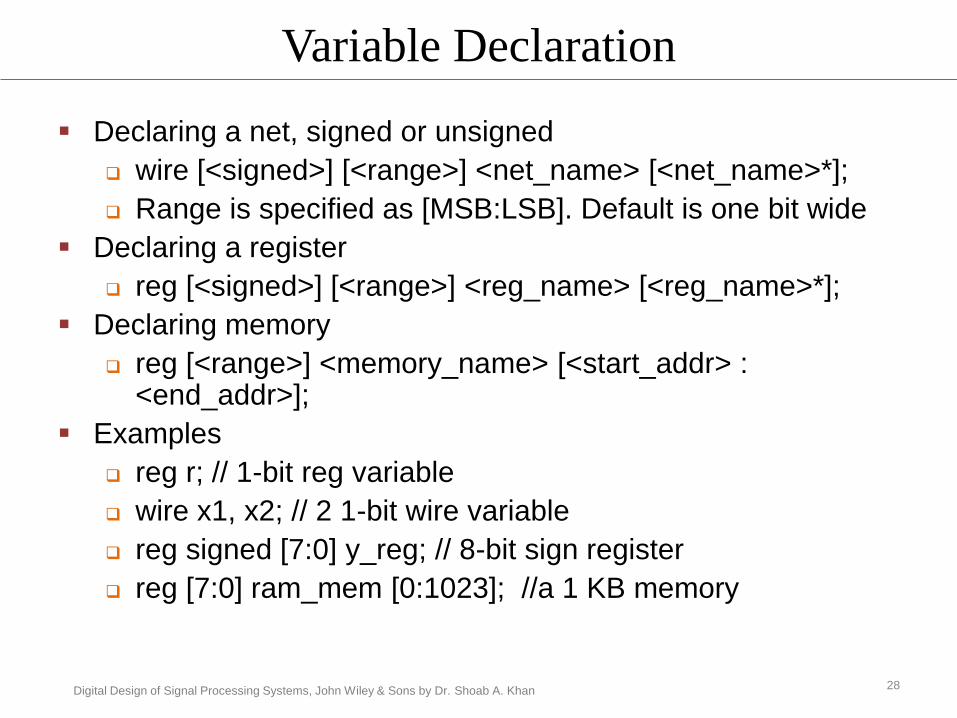
Variable Declaration
Declaring a net, signed or unsigned
wire [<signed>] [<range>] <net_name> [<net_name>*];
Range is specified as [MSB:LSB]. Default is one bit wide
Declaring a register
reg [<signed>] [<range>] <reg_name> [<reg_name>*];
Declaring memory
reg [<range>] <memory_name> [<start_addr> : <end_addr>];
Examples
reg r; // 1-bit reg variable
wire x1, x2; // 2 1-bit wire variable
reg signed [7:0] y_reg; // 8-bit sign register
reg [7:0] ram_mem [0:1023]; //a 1 KB memory
28

Digital Design of Signal Processing Systems, John Wiley & Sons by Dr. Shoab A. Khan
Constants
Constants can be written in
decimal (default)
• 13, „d13
binary
• 4‟b1101
octal
• 4‟o15
hexadecimal
• 4‟hd
29

Digital Design of Signal Processing Systems, John Wiley & Sons by Dr. Shoab A. Khan
Four Levels of Abstraction
The HW can be described at several levels of details
To capture these details Verilog provides four levels of
abstraction
1. Switch level
2. Gate level
3. Dataflow level
4. Behavioral or algorithmic level
30

Digital Design of Signal Processing Systems, John Wiley & Sons by Dr. Shoab A. Khan
Levels of Abstractions
Switch Level: The lowest level of abstraction is the
switch or transistor Level Modeling
Gate Level: Synthesis tools compile high level code
and generate code at gate level
Dataflow Level: The level of abstraction higher than
the gate level
Behavioral Level: In more complex digital designs,
priority is given to the performance and behavior at
algorithmic level 31

Digital Design of Signal Processing Systems, John Wiley & Sons by Dr. Shoab A. Khan
Gate level or structural modeling
Are build from gate primitives
Verilog has built-in gate-level primitives NAND, NOR, AND, OR, XOR, BUF, NOT, and some others
Describe the circuit using logic gates-much as you have see in an implementation of a circuit in basic logic design course
The delay can also be modeled
Typical gate instantiation is
and #delay instance-name (out, in1, in2, in3, …)
32

Digital Design of Signal Processing Systems, John Wiley & Sons by Dr. Shoab A. Khan
Example: Gate-level implementation of 2:1 MUX
using Verilog Primitives
module mux (out, in1, in2, sel);
output out;
input in1, in2, sel;
wire out1, out2, sel_n;
and #5 a1(out1, in1, sel_n);
and #5 a2(out2, in2, sel);
or #5 o1(out, out1, out2);
not n1(sel_n, sel);
endmodule
(a) (b)
outsel
in1
in2
out1
out2
33

Digital Design of Signal Processing Systems, John Wiley & Sons by Dr. Shoab A. Khan
Dataflow Modeling
Expressions, operands and operators form
the basis of dataflow modeling.
34

Digital Design of Signal Processing Systems, John Wiley & Sons by Dr. Shoab A. Khan
A list of operators for dataflow modeling
35

Digital Design of Signal Processing Systems, John Wiley & Sons by Dr. Shoab A. Khan
Arithmetic Operators
Operator Type Operator Symbol Operation Performed
Arithmetic * Multiply
/ Divide
+ Add
- Subtract
%Modulus
**Power
36
Digital Design of Signal Processing Systems, John Wiley & Sons by Dr. Shoab A. Khan
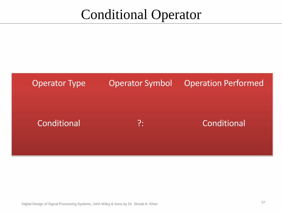
Conditional Operator
Operator Type Operator Symbol Operation Performed
Conditional ?: Conditional
37

Digital Design of Signal Processing Systems, John Wiley & Sons by Dr. Shoab A. Khan
Conditional Operator
out = sel ? a : b;
if(sel)out = a;
elseout = b;
This statement is equivalent to following decision logic.
Conditional operator can also be used to infer higher order multiplexers. The code here infers 4:1 multiplexer.
out = sel[1] ? ( sel[0] ? in3 : in2 ) : ( sel[0] ? in1 : in0 );
38
Digital Design of Signal Processing Systems, John Wiley & Sons by Dr. Shoab A. Khan
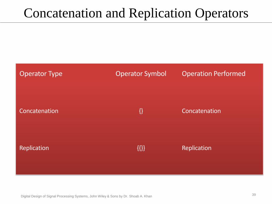
Concatenation and Replication Operators
Operator Type Operator Symbol Operation Performed
Concatenation {} Concatenation
Replication {{}} Replication
39

Digital Design of Signal Processing Systems, John Wiley & Sons by Dr. Shoab A. Khan
MSB LSB
p 13 bits
p={a[3:0], b[2:0], 3'b111, c[2:0]};
Example of Concatenation Operator
40

Digital Design of Signal Processing Systems, John Wiley & Sons by Dr. Shoab A. Khan
Example: Replication Operator
A = 2’b01;
B = {4{A}} // the replication operator
The operator replicates A four times and assigns the replicated value to B.
Thus B = 8′ b 01010101
41

Digital Design of Signal Processing Systems, John Wiley & Sons by Dr. Shoab A. Khan
Relational Operator
> Greater than
< Less than
>= Greater than or equal
<= Less than or equal
42
Relational Operator Operator Symbol Operation performed

Digital Design of Signal Processing Systems, John Wiley & Sons by Dr. Shoab A. Khan
Reduction Operators
Operator Type Operator Symbol Operation performed
Reduction &
~&
|
~|
^
^~ or ~^
Reduction and
Reduction nand
Reduction or
Reduction nor
Reduction xor
Reduction xnor
43

Digital Design of Signal Processing Systems, John Wiley & Sons by Dr. Shoab A. Khan
Bitwise Arithmetic Operators
Bitwise ~ Bitwise negation
& Bitwise AND
~& Bitwise NAND
| Bitwise OR
~| Bitwise NOR
^ Bitwise XOR
^~ or ~^ Bitwise XNOR
44
Operator Type Operator Symbol Operation performed

Digital Design of Signal Processing Systems, John Wiley & Sons by Dr. Shoab A. Khan
Equality Operators
Operator Type Operator Symbol Operation performed
Equality ==
!=
===
!==
Equality
Inequality
Case Equality
Case Inequality
45

Digital Design of Signal Processing Systems, John Wiley & Sons by Dr. Shoab A. Khan
Logical Operators
Operator Type Operator Symbol Operation Performed
Logical ! Logical Negation
|| Logical Or
&& Logical AND
46

Digital Design of Signal Processing Systems, John Wiley & Sons by Dr. Shoab A. Khan
Shift Operators
Operator Type Operator Symbol Operation Performed
Logic Shift >> Unsigned Right Shift
<< Unsigned Left Shift
Arithmetic Shift >>> Signed Right Shift
<<< Signed Left Shift
47

Digital Design of Signal Processing Systems, John Wiley & Sons by Dr. Shoab A. Khan
Example: Shift Operator
Shift an unsigned reg A = 6′b101111 by 2
B = A >> 2;
drops 2 LSBs and appends two zeros at
MSBs position, thus
B = 6′b001011
48

Digital Design of Signal Processing Systems, John Wiley & Sons by Dr. Shoab A. Khan
Example: Arithmetic Shift
Arithmetic shift right a wire A= 6′b101111 by 2
B = A >>> 2;
This operation will drop 2 LSBs and appends the
sign bit to 2 MSBs locations. Thus B is
6΄b111011.
49

Digital Design of Signal Processing Systems, John Wiley & Sons by Dr. Shoab A. Khan
Example: Reduction Operator
Apply & reduction operator on a 4-bit number A=4′b1011
assign out = &A;
This operation is equivalent to performing a bit-wise & operation on all the bits of A i.e.
out = A[0] & A[1] & A[2] & A[3];
50

Digital Design of Signal Processing Systems, John Wiley & Sons by Dr. Shoab A. Khan
Data Flow Modeling: Continuous Assignment
Continually drive wire variables
Model combinational logic
module adder_4 (a, b, ci, s, co);
input [3:0] a, b;
input ci;
output [3:0] s;
output co;
assign {co, s} = a + b + ci;
endmodule
51

Digital Design of Signal Processing Systems, John Wiley & Sons by Dr. Shoab A. Khan
module mux2_1(in1, in2, sel, out);
input in1, in2, sel;
output out;
assign out = sel ? in2: in1;
endmodule
module stimulus;
reg IN1, IN2, SEL;
wire OUT;
mux2_1 MUX(IN1, IN2, SEL, OUT);
initial
begin
IN1 = 1; IN2 = 0; SEL = 0;
#5 SEL = 1;
#5 IN1 = 0;
end
initial
$monitor($time, ": IN1=%b, IN2=%b, SEL=%b, OUT=%b\n", IN1, IN2, SEL, OUT);
endmodule
Complete Example: 2:1 Mux
The module with continuous
assignment
Stimulus to test the design
52

Digital Design of Signal Processing Systems, John Wiley & Sons by Dr. Shoab A. Khan
Behavioral Modeling
High level language constructs are used
for loop
if else
while etc
All statements come in a procedural block
Two types of procedural blocks
always
initial
A subset of constructs are synthesizable and called RTL Verilog
53

Digital Design of Signal Processing Systems, John Wiley & Sons by Dr. Shoab A. Khan
Initial and always blocks
Multiple statements per block
Procedural assignments
Timing control
control Initial blocks execute once
at t = 0 Always blocks execute continuously
at t = 0 and repeatedly thereafter
54

Digital Design of Signal Processing Systems, John Wiley & Sons by Dr. Shoab A. Khan
Initial and always blocks
initial
begin
end
procedural
assignment 1
procedural
assignment 2
procedural
assignment 3
always
begin
end
procedural
assignment 1
procedural
assignment 2
procedural
assignment 3
55

Digital Design of Signal Processing Systems, John Wiley & Sons by Dr. Shoab A. Khan
Initial Block
This block starts with initial keyword
This is non synthesizable
Non RTL
This block is used only in stimulus
All initial blocks execute concurrently in arbitrary
order
They execute until they come to a #delay operator
Then they suspend, putting themselves in the
event list delay time units in the future
At delay units, they resume executing where they
left off56

Digital Design of Signal Processing Systems, John Wiley & Sons by Dr. Shoab A. Khan
Procedural assignments
Blocking assignment =
Regular assignment inside procedural block
Assignment takes place immediately
LHS must be a register
always
begin
A = BB = A
end
A=B, B=B
57

Digital Design of Signal Processing Systems, John Wiley & Sons by Dr. Shoab A. Khan
Procedural assignments
Nonblocking assignment <=
Compute RHS
Assignment takes place at end of block
LHS must be a register
always
begin
A <= BB <= A
end
Swap A and B
58

Digital Design of Signal Processing Systems, John Wiley & Sons by Dr. Shoab A. Khan
Blocking Procedural Assignment with three methods
of writing sensitivity list
reg sum, carry;
always @ (x or y)
begin
sum = x^y;
carry = x&y;
end
reg sum, carry;
always @ (x, y)
begin
sum = x^y;
carry = x&y;
End
reg sum, carry;
always @ (*)
begin
sum = x^y;
carry = x&y;
end
(a) (b) (c)
(a) Verilog-95 style (b) Verilog-2001 support of comma separated sensitivity list
(c) Verilog-2001 style that only writes * in the list
59

Digital Design of Signal Processing Systems, John Wiley & Sons by Dr. Shoab A. Khan
# Time Control
$time
A built-in variable that represents simulated time
a unitless integer
$display($time, “a=%d”, a);
# Time Control
#<number> statement
statement is not executed until <number> time units have
passed
control is released so that other processes can execute
used in test code
used to model propagation delay in combinational logic
60

Digital Design of Signal Processing Systems, John Wiley & Sons by Dr. Shoab A. Khan
# Time Control
Delay parameter for a built-in logic gate
wire c;
xor #2 x2(c, a, b);
61

Digital Design of Signal Processing Systems, John Wiley & Sons by Dr. Shoab A. Khan
@ Time Control
@(*)
@(expression)
@(expression or expression or …)
@(posedge onebit)
@(negedge onebit)
do not execute statement until event occurs
@(clk) is same as @(posedge clk or negedge
clk)
62

Digital Design of Signal Processing Systems, John Wiley & Sons by Dr. Shoab A. Khan
Code with non blocking procedural
assignment
reg sum_reg, carry_reg;
always @ (posedge clk)
begin
sum_reg <= x^y;
carry_reg <= x&y;
end
63

Digital Design of Signal Processing Systems, John Wiley & Sons by Dr. Shoab A. Khan
Time Control # and @
$display ($time, “a=%d”, a);
always @ (a or b)
c = a^b; // combinational logic
always @(posedge clk)
c_reg <= c; // sequential register
64
Digital Design of Signal Processing Systems, John Wiley & Sons by Dr. Shoab A. Khan
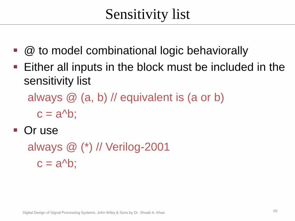
Sensitivity list
@ to model combinational logic behaviorally
Either all inputs in the block must be included in the
sensitivity list
always @ (a, b) // equivalent is (a or b)
c = a^b;
Or use
always @ (*) // Verilog-2001
c = a^b;
65
Digital Design of Signal Processing Systems, John Wiley & Sons by Dr. Shoab A. Khan
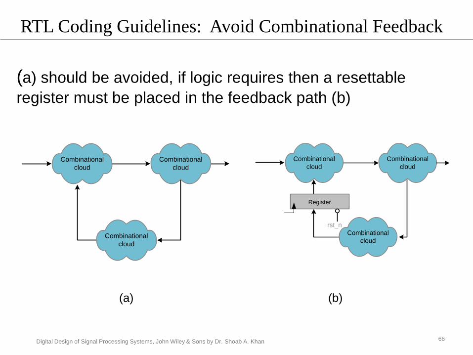
RTL Coding Guidelines: Avoid Combinational Feedback
Combinational
cloud
Combinational
cloud
Combinational
cloud
(a) (b)
Combinational
cloud
Combinational
cloud
Register
rst_n
Combinational
cloud
(a) should be avoided, if logic requires then a resettable
register must be placed in the feedback path (b)
66

Digital Design of Signal Processing Systems, John Wiley & Sons by Dr. Shoab A. Khan
Inferring Resettable Register
(a) Verilog code to infer a register with asynchronous active
low reset (b) Verilog code to infer a register with
asynchronous active high reset
(a) (b)
// register with asynchronous
active low reset
always @ (posedge clk or negedge
rst_n)
begin
If (! rst_n)
r_reg <= 4’b0;
else
r_reg <= data;
end
endmodule
// register with asynchronous
active high reset
always @ (posedge clk or posedge
rst)
begin
If (rst)
r_reg <= 4’b0;
else
r_reg <= data;
end
endmodule
67

Digital Design of Signal Processing Systems, John Wiley & Sons by Dr. Shoab A. Khan
Inferring Resettable Register
(a) Verilog code to infer a register with synchronous
active low reset
(b) Verilog code to infer a register with synchronous
active high reset
// register with synchronous
active low reset
always @ (posedge clk)
begin
If (! rst_n)
r_reg <= 4’b0;
else
r_reg <= data;
end
endmodule
// register with synchronous
active high reset
always @ (posedge clk)
begin
If (rst)
r_reg <= 4’b0;
else
r_reg <= data;
end
endmodule
(a) (b)68

Digital Design of Signal Processing Systems, John Wiley & Sons by Dr. Shoab A. Khan
Using asynchronous reset in implementing an accumulator
// Register with asynchronous active-low reset
always @ (posedge clk or negedge rst_n)
begin
if(!rst_n)
acc_reg <= 16’b0;
else
acc_reg <= data+acc_reg;
end
// Register with asynchronous active-high reset
always @ (posedge clk or posedge rst)
begin
if(rst)
acc_reg <= 16’b0;
else
acc_reg <= data+acc_reg;
end
+ 16
clk
acc_reg
rst_n
4
data
Example: An Accumulator
69

Digital Design of Signal Processing Systems, John Wiley & Sons by Dr. Shoab A. Khan
Generating Clock in Stimulus
initial // All the initializations should be in the initial block
begin
clk = 0; // clock signal must be initialized to 0
# 5 rst_n = 0; // pull active low reset signal to low
# 2 rst_n=1; // pull the signal back to high
end
always // generate clock in an always block
#10 clk=(~clk);
70

Digital Design of Signal Processing Systems, John Wiley & Sons by Dr. Shoab A. Khan
Conditional Execution: case statement
module mux4_1(in1, in2, in3, in4, sel, out);
input [1:0] sel;
input [15:0] in1, in2, in3, in3;
output [15:0] out;
reg [15:0] out;
always @(*)
case (sel)
2'b00: out = in1;
2'b01: out = in2;
2'b10: out = in3;
2'b11: out = in4;
default: out = 16'bx;
endcase
endmodule
Like C and other high-level programming languages, Verilog supports
switch and case statements for multi-way decision support.
71

Digital Design of Signal Processing Systems, John Wiley & Sons by Dr. Shoab A. Khan
casex and casez statements
To make comparison with the „don‟t care‟
casez takes z as don‟t care
casex takes z and x as don‟t care
always @(op_code)
begin
casez (op_code)
4’b1???: alu_inst(op_code);
4’b01??: mem_rd(op_code);
4’b001?: mem_wr(op_code);
endcase
end
72

Digital Design of Signal Processing Systems, John Wiley & Sons by Dr. Shoab A. Khan
Conditional Statements: if-else
Verilog supports conditional statements
if-else
if-(else if)-else
if (brach_flag)
PC = brach_addr
else
PC = next_addr;
always @(op_code)
begin
if (op_code == 2’b00)
cntr_sgn = 4’b1011;
else if (op_code == 2’b01)
cntr_sgn = 4’b1110;
else
cntr_sgn = 4’b0000;
end
73

Digital Design of Signal Processing Systems, John Wiley & Sons by Dr. Shoab A. Khan
RTL Coding Guideline: Avoid Latches in the Design
A latch is a storage device that stores a value without the
use of a clock.
Latches are technology-specific and must be avoided in
synchronous designs
To avoid latches adhere to coding guidelines
fully specify assignments or use a default assignment
out_b is not assigned any value under else, the synthesis tool will infer a latch
input [1:0] sel;reg [1:0] out_a, out_b;
always @ (*)begin
if (sel == 2’b00)begin
out_a = 2’b01;out_b = 2’b10;
endelse
out_a = 2’b01;end
74

Digital Design of Signal Processing Systems, John Wiley & Sons by Dr. Shoab A. Khan
Avoiding Latches
Use default assignmentsinput [1:0] sel;reg [1:0] out_a, out_b;
always @ (*)begin
out_a = 2’b00;out_b = 2’b00;if (sel=2’b00)begin
out_a = 2’b01;out_b = 2’b10;
endelse
out_a = 2’b01;end
75

Digital Design of Signal Processing Systems, John Wiley & Sons by Dr. Shoab A. Khan
Avoid Latches
input [1:0] sel;
reg [1:0] out_a, out_b;
always @*
begin
out_a = 2’b00;
out_b = 2’b00;
if (sel==2’b00)
begin
out_a = 2’b01;
out_b = 2’b10;
end
else if (sel == 2’b01)
out_a = 2’b01;
end
All conditions to be checked
For if block there must be an else
For case, either check all conditions or use a default
always @*
begin
out_a = 2’b00;
out_b = 2’b00;
if (sel==2’b00)
begin
out_a = 2’b01;
out_b = 2’b10;
end
else if (sel == 2’b01)
out_a = 2’b01;
else
out_a = 2’b00;
end
76

Digital Design of Signal Processing Systems, John Wiley & Sons by Dr. Shoab A. Khan
Avoid Latches
Correct use of case statements and
default assignments
always @*
begin
out_a = 2’b00;
out_b = 2’b00;
case (sel)
2’b00:
begin
out_a = 2’b01;
out_b = 2’b10;
end
2’b01:
out_a = 2’b01;
default:
out_a = 2’b00;
endcase
end 77

Digital Design of Signal Processing Systems, John Wiley & Sons by Dr. Shoab A. Khan
Loop Statements
Loop statements are used to execute a block of statements multiple times repeat, while, for, forever
In RTL a loop infers multiple instances of the logic in loop body
i=0;
while (i<5)
begin
$display("i=%d\n", i);
i=i+1;
end
i=0;
repeat (5)
begin
$display("i=%d\n", i);
i=i+1;
end
for (i=0; i<5; i=i+1)
begin
$display("i=%d\n", i);
end
78

Digital Design of Signal Processing Systems, John Wiley & Sons by Dr. Shoab A. Khan
Port Definitions
Input Ports
Always wire
Output Ports
wire if dataflow modeling constructs are used
reg if behavioral modeling I.e. assignment is
made in a procedural block
Inout Ports
always wire
79

Digital Design of Signal Processing Systems, John Wiley & Sons by Dr. Shoab A. Khan
Ports and Data Types
Arrow analogy
Head is always wire
Tail wire or reg
• wire if continuous assignment
• reg is procedural assignment
register/wire wire
wire
wire
register/wire wire
input output
inout
module0module1 module2
80

Digital Design of Signal Processing Systems, John Wiley & Sons by Dr. Shoab A. Khan
Simulation Control
$finish Specifies when simulation ends
$stop Suspends the simulation and enters
interactive mode
$display Prints output using format similar
to C and creates a new line
$monitor Similar to $display but active all
the time
81

Digital Design of Signal Processing Systems, John Wiley & Sons by Dr. Shoab A. Khan
$monitor
Prints its string when one of the listed values
changes
Only one monitor can be active at any time
Prints at the end of current simulation time
Display is like printf( )
$monitor ( $time, “A=%d, B=%d, CIN=%b,
SUM=%d, COUT=%d”, A, B, CIN, COUT );
$display ( $time, “A=%d, B=%d, CIN=%b,
SUM=%d, COUT=%d”, A, B, CIN, COUT );
82

Digital Design of Signal Processing Systems, John Wiley & Sons by Dr. Shoab A. Khan
module irr(
input signed [15:0] x,
input clk, rst_n,
output reg signed [31:0] y);
reg signed [31:0] y_reg;
always @(*)
y =(y_reg>>>1) + x; // combinational logic
always @(posedge clk or negedge rst_n) // sequential logic
begin
if (!rst_n)
y_reg <= 0;
else
y_reg <= y;
end
endmodule
The RTL Verilog code implementing a single tap IIR filter
y[n]=0.5y[n-1]+x[n]
Example
83

Digital Design of Signal Processing Systems, John Wiley & Sons by Dr. Shoab A. Khan
Stimulus for the IIR filter design module
module stimulus_irr;
reg [15:0] X;
reg CLK, RST_N;
wire [31:0] Y;
integer i;
irr IRR0(X, CLK, RST_N, Y);
initial
begin
CLK = 0;
#5 RST_N = 0;
#2 RST_N = 1;
end
initial
begin
X = 0;
for(i=0; i<10; i=i+1)#20 X = X + 1;
$finish;end
always#10 CLK = ~CLK;
initial $monitor($time, " X=%d, sum=%d,
Y=%d", X, IRR0.y, Y);
initial begin
#60 $stop;end
endmodule
84

Digital Design of Signal Processing Systems, John Wiley & Sons by Dr. Shoab A. Khan
Timing diagram for the IIR filter design
Value 0 Value 1 Value 2
Value 1 Value 2
x
Value 0
x
x
y_reg
10 time
units
10 time
units
10 time
units10 time
unitsclk
rst_n
y
10 time
units
0
10 time
units
10 time
units10 time
units
85

Digital Design of Signal Processing Systems, John Wiley & Sons by Dr. Shoab A. Khan
A dump of timing diagram from ModelSim simulator
86
Digital Design of Signal Processing Systems, John Wiley & Sons by Dr. Shoab A. Khan
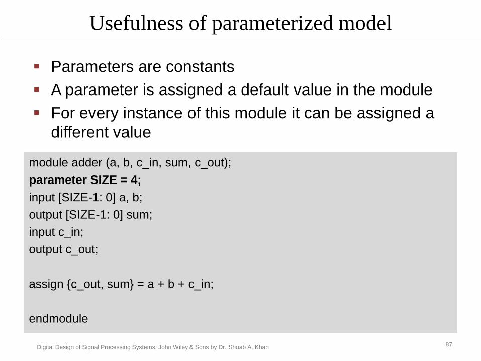
Usefulness of parameterized model
module adder (a, b, c_in, sum, c_out);
parameter SIZE = 4;
input [SIZE-1: 0] a, b;
output [SIZE-1: 0] sum;
input c_in;
output c_out;
assign {c_out, sum} = a + b + c_in;
endmodule
Parameters are constants
A parameter is assigned a default value in the module
For every instance of this module it can be assigned a
different value
87
Digital Design of Signal Processing Systems, John Wiley & Sons by Dr. Shoab A. Khan
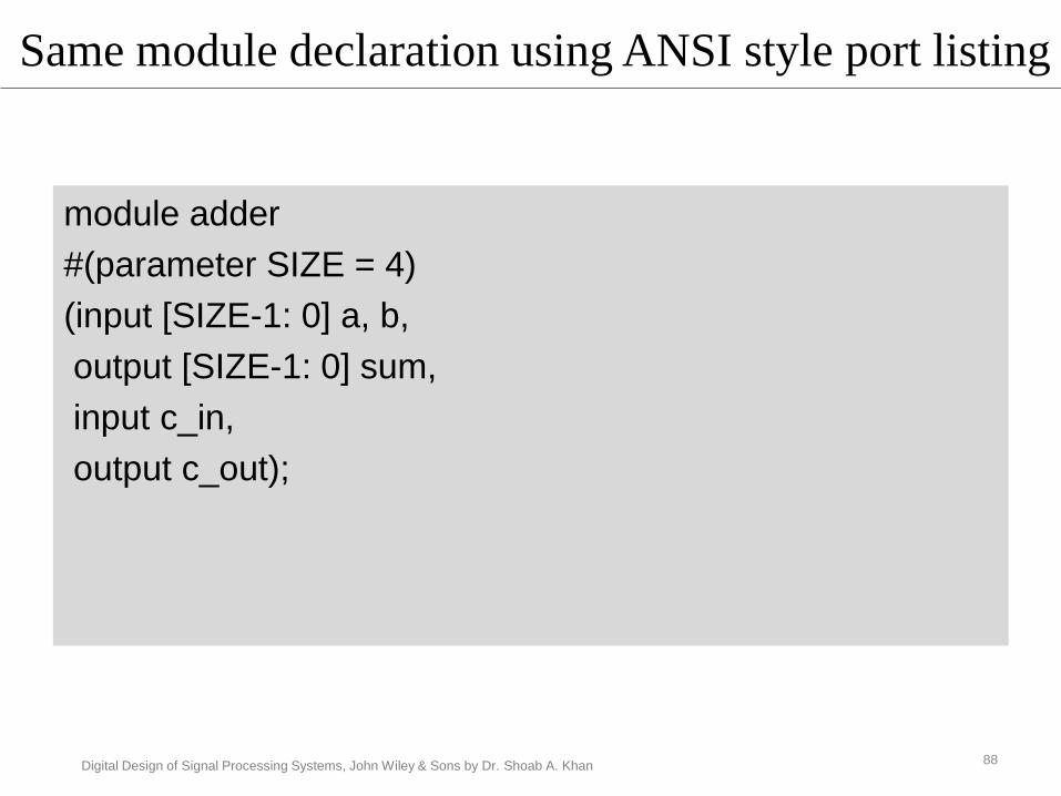
Same module declaration using ANSI style port listing
module adder
#(parameter SIZE = 4)
(input [SIZE-1: 0] a, b,
output [SIZE-1: 0] sum,
input c_in,
output c_out);
88

Digital Design of Signal Processing Systems, John Wiley & Sons by Dr. Shoab A. Khan
Instantiation of the module for adding 8-bit
inputs in1 and in2
module stimulus;
reg [7:0] in1, in2;
wire [7:0] sum_byte;
reg c_in;
wire c_out;
adder #8 add_byte (in1, in2, c_in, sum_byte, c_out);
.
.
endmodule
89

Digital Design of Signal Processing Systems, John Wiley & Sons by Dr. Shoab A. Khan
In Verilog the parameter value can also be
specified by name
adder #(.SIZE(8)) add_byte (in1, in2, c_in,
sum_byte, c_out);
90

Digital Design of Signal Processing Systems, John Wiley & Sons by Dr. Shoab A. Khan
Parameterized code
module adder
#(parameter SIZE1 = 4, SIZE2=6)
(input [SIZE1-1: 0] a,
Input [SIZE2-1: 0] b,
output [SIZE2-1: 0] sum,
input c_in,
output c_out);
91

Digital Design of Signal Processing Systems, John Wiley & Sons by Dr. Shoab A. Khan
Loading memory data from a file
$readmemb (“memory.dat”, mem);
The statement loads data in memory.dat file into mem.
92

Digital Design of Signal Processing Systems, John Wiley & Sons by Dr. Shoab A. Khan
Macros
`define DIFFERENCE 6‟b011001
The use of the define tag is shown here.
if (ctrl == `DIFFERENCE)
93

Digital Design of Signal Processing Systems, John Wiley & Sons by Dr. Shoab A. Khan
Preprocessing commands
`ifdef G723
$display (“G723 execution”);
`else
$display (“other codec execution”);
`endif
94

Digital Design of Signal Processing Systems, John Wiley & Sons by Dr. Shoab A. Khan
Instead of making multiple copy of common code, it can be written as a task and called multiple times
Task definition occurs inside a module Task is called only from initial and always blocks and
other tasks in that module
Task contains any behavioral statements, including time control
Order of input, output, and inout definitions determines binding of arguments input argument may not be reg
output arguments must be reg
Task
95

Digital Design of Signal Processing Systems, John Wiley & Sons by Dr. Shoab A. Khan
task name;
input arguments;
output arguments;
inout arguments;
…
declarations;
begin
statement;
…
end
endtask
Task template
96

Digital Design of Signal Processing Systems, John Wiley & Sons by Dr. Shoab A. Khan
Example: Taskmodule RCA(
input [3:0] a, b,
input c_in,
output reg c_out,
output reg [3:0] sum
);
reg carry[4:0];
integer i;
task FA(
input in1, in2, carry_in,
output reg out, carry_out);
{carry_out, out} = in1 + in2 + carry_in;
endtask
always@*
begin
carry[0]=c_in;
for(i=0; i<4; i=i+1)
begin
FA(a[i], b[i], carry[i], sum[i], carry[i+1]);
end
c_out = carry[4];
end
endmodule
97

Digital Design of Signal Processing Systems, John Wiley & Sons by Dr. Shoab A. Khan
Functions
The common code can also be written as function
Function implements combinational behavior
No timing controls or tasks
May call other functions with no recursion
No output or inout allowed
Output is an implicit register having name and
range of function
98

Digital Design of Signal Processing Systems, John Wiley & Sons by Dr. Shoab A. Khan
Functions template
Syntax:
function_declaration
function [range or type] function_identifier;
function_call
function_identifier (expression {, expression})
99

Digital Design of Signal Processing Systems, John Wiley & Sons by Dr. Shoab A. Khan
Example: Functionmodule MUX4to1(
input [3:0] in,
input [1:0] sel,
output out);
wire out1, out2;
function MUX2to1;
input in1, in2;
input select;
assign MUX2to1 = select ? in2:in1;
endfunction
assign out1 = MUX2to1(in[0], in[1], sel[0]);
assign out2 = MUX2to1(in[2], in[3], sel[0]);
assign out = MUX2to1(out1, out2, sel[1]);
endmodule
module testFunction;
reg [3:0] IN;
reg [1:0] SEL;
wire OUT;
MUX4to1 mux(IN, SEL, OUT);
initial
begin
IN = 1;
SEL = 0;
#5 IN = 7;
SEL = 0;
#5 IN = 2; SEL=1;
#5 IN = 4; SEL = 2;
#5 IN = 8; SEL = 3;
end
initial
$monitor($time, " %b %b %b\n", IN, SEL, OUT);
endmodule 100

Digital Design of Signal Processing Systems, John Wiley & Sons by Dr. Shoab A. Khan
CASE STUDY of design of a communication
receiver is covered in the book
101

Digital Design of Signal Processing Systems, John Wiley & Sons by Dr. Shoab A. Khan
Verilog Testbench
A testbench facilitates verification of a design or
module by providing test vectors and comparing
the response to the expected response
The design (top- evel module) is instantiated
inside the testbench, and a model or expected
outputs are used to evaluate the response
Constructs that are not synthesizable can be
used in stimulus
102

Digital Design of Signal Processing Systems, John Wiley & Sons by Dr. Shoab A. Khan
RTL
COMPARISON
simulator
Test Vectors
TRUE
FALSE
log ERROR
Testing RTL Design
Make a simulation
model
Generate and give
test vectors to both
Test against the
model
103

Digital Design of Signal Processing Systems, John Wiley & Sons by Dr. Shoab A. Khan
Behavioral Modeling
A set of inputs is applied and the outputs are checked
against the specification or
expected output
No consideration to the inner details of the system
Testing against specifications while making use of the known internal structure of the system.
Enables easy location of bug for quick fixing
Performed by the developer
Test Cases
generationDUT
Comparisons
Log the
values in
case of
mismatch
stimulus
actual
Output
expected
Output
diff
Test Cases
generation
Log the
values in
case of
mismatch
stimulus
actual
Output
expected
Output
diff
Comparisons
Expected interval state
Actual
interval
state
(a) Black-box testing (b) While-box level testing
104

Digital Design of Signal Processing Systems, John Wiley & Sons by Dr. Shoab A. Khan
An Example Verification Setup
Transactor
C++ test vector
generator
Checker Transactor
C++ Implementation
Coverage
TLM
Transactor
C++ test vector
generator
Checker Transactor
C++ Implementation
Coverage
DUT
Driver Monitor
RTL
TRANSLATOR
TLM
105

Digital Design of Signal Processing Systems, John Wiley & Sons by Shoab A. Khan
Adv Digital Design Contents
System Verilog
106

Digital Design of Signal Processing Systems, John Wiley & Sons by Dr. Shoab A. Khan
SystemVerilog
SystemVerilog (SV) offers a unified language
that is very powerful to model complex systems
SV advanced constructs facilitate concise writing
of test benches and analyzing the coverage.
Most of the EDA tool vendors are continuously
adding support of SV
107

Digital Design of Signal Processing Systems, John Wiley & Sons by Dr. Shoab A. Khan
Additional data types in SystemVerilog
Data Type Description States Example
logic User defined 4 states 0,1, x ,z logic [15:0] a,b;
int 32 bit signed 2 states 0,1 int num;
bit User defined 2 states 0,1 bit [5:0] in;
byte 8 bit signed 2 states 0,1 byte t;
longint 64 bit signed 2 states 0,1 longint p;
shortint 16 bit signed 2 states 0,1 shortint q;
108

Digital Design of Signal Processing Systems, John Wiley & Sons by Dr. Shoab A. Khan
Data Types
A logic type is similar to a reg
Can take any one of the four values 0,1,x,z
In rest of the data types each bit can be a
0 and 1.
These variables are auto initialized to 0 at
time zero
109

Digital Design of Signal Processing Systems, John Wiley & Sons by Dr. Shoab A. Khan
Packed & unpacked 1-D and 2-D arrays
bit up_data [15:0];
bit [31:0] up_mem [0:511];
bit [15:0] p_data;
bit [31:0][0:511] p_mem1, p_mem2;
slice_data = up_mem [2][31:15]; // most significant byte at mem location 2
add_mem = p_mem1 + p_mem2;
bit [15:0] array[];
array = new[1023];
SV can operate on an entire two-dimensional (2-D) array of packed data
Unpacked arrays can be operated only on an indexed value
Dynamic arrays can also be declared as
110

Digital Design of Signal Processing Systems, John Wiley & Sons by Dr. Shoab A. Khan
Module Instantiation and Port Listing
module FA(in1, in2, sum, clk, rest_n);
Assuming the instance has first three ports with the same name, the instance can be written as
FA ff (.in1, .sum, .in2, .clk(clk_global), .rest_n(rst_n));
Or more concisely as
FA ff (.*, .clk(clk_global), .rest_n (rst_n));
111

Digital Design of Signal Processing Systems, John Wiley & Sons by Dr. Shoab A. Khan
C/C++ like Constructs
• typedef, struct and enum
typedef bit [15:0] addr;
typedef struct {
addr src;
addr dst;
bit [31:0] data;
} packet_tcp;
module packet ( input packet_tcp packet_in,
input clk,
output packet_tcp packet_out);
always_ff @(posedge clk)
begin
packet_out.dst <= packet_in.src;
packet_out.src <= packet_in.dst;
packet_out.data <= ~packet_in.data;
end
endmodule
112

Digital Design of Signal Processing Systems, John Wiley & Sons by Dr. Shoab A. Khan
Enum
typedef enum logic [2:0]
{ idle = 0,
read = 3,
dec, // = 4
exe
} states;
states pipes;
The enum can also be directly defined asenum {idle, read=3, dec, exe} pipes;
case (pipes)
idle: pc = pc;
read: pc = pc+1;
.
.
endcase
113

Digital Design of Signal Processing Systems, John Wiley & Sons by Dr. Shoab A. Khan
Operators
Operand1 Op = Operand2
X += 2;
Increment/decrement
Op ++, Op--, ++Op, --Op
i++
114

Digital Design of Signal Processing Systems, John Wiley & Sons by Dr. Shoab A. Khan
for and do-while Loops
do
begin
if (sel_1 == 0)
continue;
if (sel_2 == 3) break;
end
while (sel_2==0);
for( integer i=0, j=0, k=0; i+j+k < 20; i++, j++, k++)
115

Digital Design of Signal Processing Systems, John Wiley & Sons by Dr. Shoab A. Khan
Procedural Block: always
module adder(input signed [3:0] in1, in2,
input clk, rst_n,
output logic signed [15:0] acc);
logic signed [15:0] sum;
// combinational block
always_comb
begin: adder
sum = in1 + in2 + acc;
end: adder
// sequential block
always_ff @(posedge clk or negedge rst_n)
if (!rst_n)
acc <= 0;
else
acc <= sum;
endmodule
always_comb , always_latch and always_ffSV solves the issue of sensitivity list
116

Digital Design of Signal Processing Systems, John Wiley & Sons by Dr. Shoab A. Khan
Procedural Block: final
final
begin
$display($time, “ simulation time, the simulation ends\n”);end
117
Digital Design of Signal Processing Systems, John Wiley & Sons by Dr. Shoab A. Khan
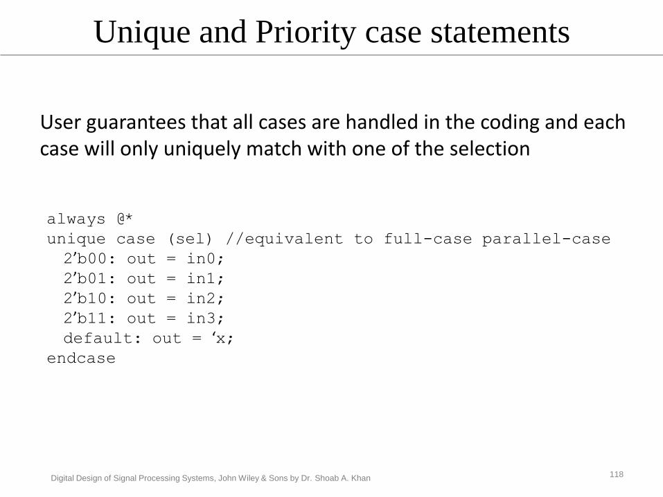
Unique and Priority case statements
User guarantees that all cases are handled in the coding and each case will only uniquely match with one of the selection
always @*
unique case (sel) //equivalent to full-case parallel-case
2’b00: out = in0;2’b01: out = in1;2’b10: out = in2;2’b11: out = in3;default: out = ‘x;
endcase
118
Digital Design of Signal Processing Systems, John Wiley & Sons by Dr. Shoab A. Khan
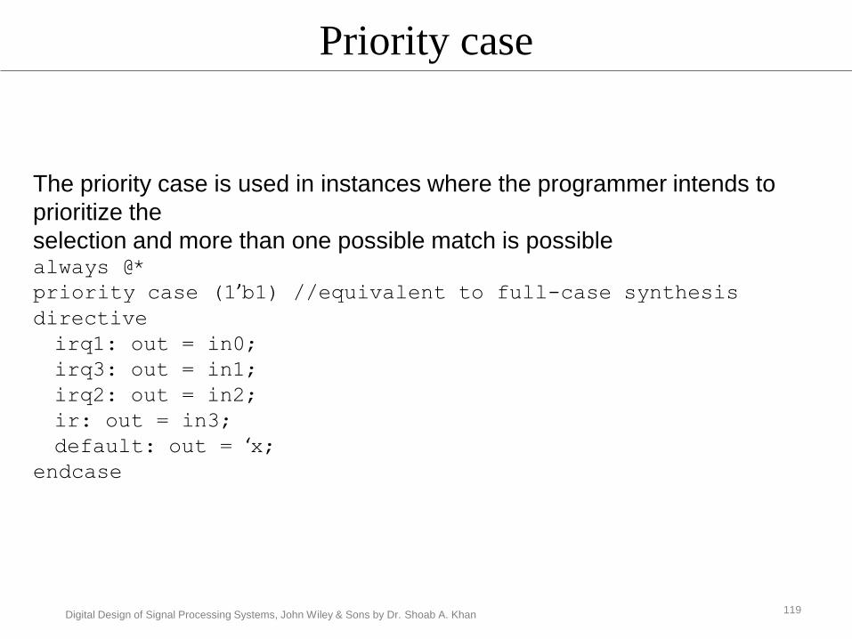
Priority case
The priority case is used in instances where the programmer intends to
prioritize the
selection and more than one possible match is possible always @*
priority case (1’b1) //equivalent to full-case synthesis directive
irq1: out = in0;
irq3: out = in1;
irq2: out = in2;
ir: out = in3;
default: out = ‘x;endcase
119

Digital Design of Signal Processing Systems, John Wiley & Sons by Dr. Shoab A. Khan
Priority case
always @*unique case (sel) //equivalent to full-case parallel-
case synthesis directive2’b00: out = in0;2’b01: out = in1;2’b10: out = in2;2’b11: out = in3;default: out = ‘x;
endcase
User guarantees that all cases are handled in the coding and each case
will only uniquely match with one of the selections
120

Digital Design of Signal Processing Systems, John Wiley & Sons by Dr. Shoab A. Khan
Nested Modules
module accumulator(input clk, rst_n, input [7:0] data, output bit [15:0] acc);
always_ff @ (posedge clk)
begin
if (!rst_n)
acc <= 0;
else
acc <= acc + data;
end
endmodule
logic clk=0;
always #1 clk = ~clk;
logic rst_n;
logic [7:0] data;
logic [15:0] acc_reg;
accumulator acc_inst(clk, rst_n, data, acc_reg);
initial
begin
rst_n = 0;
#10 rst_n = 1;
data = 2;
#200 $finish;
end
initial
$monitor($time, "%d, %d\n", data, acc_reg);
endmodule
121

Digital Design of Signal Processing Systems, John Wiley & Sons by Dr. Shoab A. Khan
SV Function
No begin and end to place multiple
statements
SV functions can return a void.
Addition of the return statement is also
added
The input and output can also be passed
by name
122

Digital Design of Signal Processing Systems, John Wiley & Sons by Dr. Shoab A. Khan
Functions and Tasks
function void expression (input integer a, b, c, output integer d);
d = a+b-c;
endfunction: expression
function integer divide (input integer a, b);if (b)
divide = a/b;elsebegin
$display(“divide by 0\n”);return (‘hx);
end// rest of the function
.
.endfunction: divide
123

Digital Design of Signal Processing Systems, John Wiley & Sons by Dr. Shoab A. Khan
Interface
A major addition
It encapsulates connectivity and replaces a
group of ports and their interworking with a
single identity
The interface can contain
Parameters
Constants
Variables
functions and tasks.
124

Digital Design of Signal Processing Systems, John Wiley & Sons by Dr. Shoab A. Khan
A Local Bus interface between two modules
32
8
addr
1rqst
1grant
1
done
data
Local Bus
125

interface local_bus(input logic clk);
bit rqst;
bit grant;
bit rw;
bit [4:0] addr;
wire [7:0] data;
modport tx (input grant,
output rqst, addr,rw,
inout data,
input clk);
modport rx (output grant,
input rqst, addr, rw,
inout data,
input clk);
endinterface
module src (input bit , clk,
local_bus.tx busTx);
integer i;
logic [7:0] value = 0;
assign busTx.data = value;
initial
begin
busTx.rw = 1;
for (i=0; i<32; i++)
begin126

#2 busTx.addr = i;value += 1;
endbusTx.rw = 0;
end// rest of the modules detail hereendmodule
module dst ( input bit clk,local_bus.rx busRx);logic [7:0] local_mem [0:31];
always @(posedge clk)if (busRx.rw)local_mem[busRx.addr] = busRx.data;
endmodule
// In the top-level module these modules are instantiated with interface declaration. module local_bus_top;
logic clk = 0;local_bus bus(clk); // the interface declaration
always #1 clk = ~clk;
src SRC (clk, bus.tx);dst DST (clk, bus.rx);
initial$monitor ($time, "\t%d %d %d %d\n", bus.rx.rw, bus.rx.addr, bus.rx.data, DST.local_mem[bus.rx.addr]);
endmodule
127

Digital Design of Signal Processing Systems, John Wiley & Sons by Dr. Shoab A. Khan
Class
A class consists of data and methods.
The methods are functions and tasks that
operate on the data in the class.
SV supports key aspects of OOP
Inheritance
encapsulation
polymorphism
128
Digital Design of Signal Processing Systems, John Wiley & Sons by Dr. Shoab A. Khan
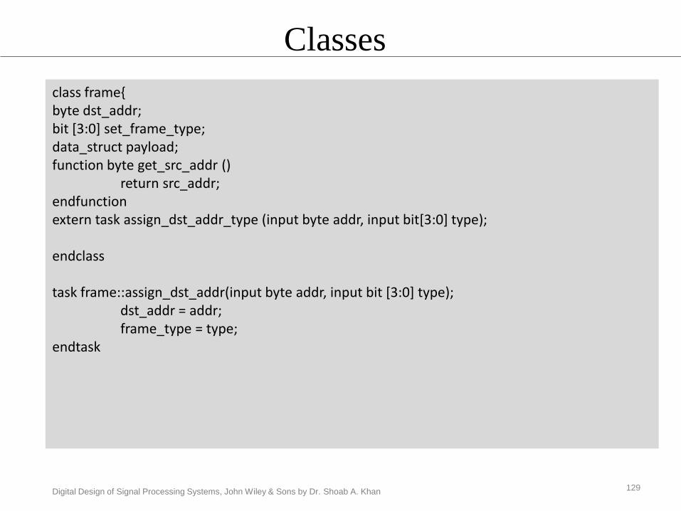
Classes
class frame{byte dst_addr;bit [3:0] set_frame_type;data_struct payload;function byte get_src_addr ()
return src_addr;endfunctionextern task assign_dst_addr_type (input byte addr, input bit[3:0] type);
endclass
task frame::assign_dst_addr(input byte addr, input bit [3:0] type);dst_addr = addr;frame_type = type;
endtask
129

Digital Design of Signal Processing Systems, John Wiley & Sons by Dr. Shoab A. Khan
frame first_frame = new;
A class constructor can also be used to initialize data as
class frame{..function new (input byte addr, input [3:0] type)
dst_addr = addr;frame_type = type;
endfunction..endclass
130

Digital Design of Signal Processing Systems, John Wiley & Sons by Dr. Shoab A. Khan
frame msg_frame = new(8’h00, MSG); // set the dst and type of the frame
class warning_frame extends frame;bit [2:0] warning_type;
function MSG_TYPE send_warning ();return warning_type;
endfuction;endclass
131

Digital Design of Signal Processing Systems, John Wiley & Sons by Dr. Shoab A. Khan
Direct Programming Interface
SV can directly access a function written in C
using a DPI
A function or task written in SV can be exported
to a C program.
Interworking of C and SV code very trivial
The C functions in SV are called using import
directive,
While functions and tasks of SV in a C function
are accessible by using export DPI declaration
132

Digital Design of Signal Processing Systems, John Wiley & Sons by Dr. Shoab A. Khan
Direct Programming Interface (DPI)
// top level module that instantiates a module that Calls a C functionmodule top_level();
moduleCall_C Call_C (rst, clk, in1, in2, out1, …);...endmodule
The instantiated module Call_C of type moduleCall_C uses import directive for interfacing with C program.
module moduleCall_C(rst, clk, in1, in2, out1,...);..import "DPI-C" context task fuctionC (....);
always@(posedge clk)functionC (rst,in1, in2, out1,....);
export "DPI-C" task CallVeri1;export "DPI-C" task CallVeri2;
task CallVeri1 (input int addr1, output int data1);..endtasktask CallVeri2 (input int addr2, output int data2);..endtask..endmodule
133

Digital Design of Signal Processing Systems, John Wiley & Sons by Dr. Shoab A. Khan
// required header files
void fuctionC (int rst, ....){..
rest = rst;.
funct1(...);funct2(...);
.
.}
void funct1 (void){..
CallVeri1(....);.}
void funct2 (void){..
CallVeri2(....);.}
134

Digital Design of Signal Processing Systems, John Wiley & Sons by Dr. Shoab A. Khan
Assertion
SV supports two types of assertions
immediate
concurrent
The immediate assertion is like an if-else statemen
The expression in assert is checked for the desired behavior
If this expression fails
SV provides one of the three severity system tasks • $warning, $error and $fatal.
Concurrent assertion checks the validity of a property
135

Digital Design of Signal Processing Systems, John Wiley & Sons by Dr. Shoab A. Khan
Assertion
assert(value>=5)
else $warning(“Value above range”);
assert property (request && !ready)
assert property (@posedge clk) req |-> ##[2:5] grant);
136
Digital Design of Signal Processing Systems, John Wiley & Sons by Dr. Shoab A. Khan
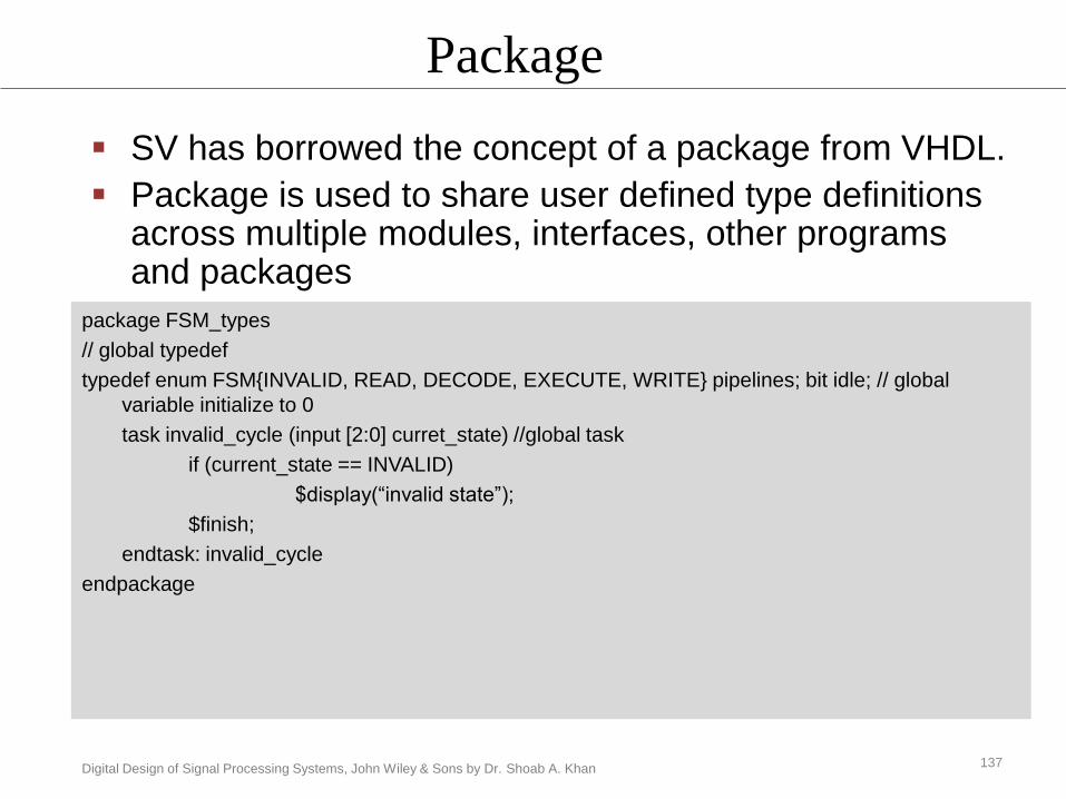
Package
package FSM_types
// global typedef
typedef enum FSM{INVALID, READ, DECODE, EXECUTE, WRITE} pipelines; bit idle; // global
variable initialize to 0
task invalid_cycle (input [2:0] curret_state) //global task
if (current_state == INVALID)
$display(“invalid state”);
$finish;
endtask: invalid_cycle
endpackage
SV has borrowed the concept of a package from VHDL.
Package is used to share user defined type definitions across multiple modules, interfaces, other programs and packages
137

Digital Design of Signal Processing Systems, John Wiley & Sons by Dr. Shoab A. Khan
Randomization
bit [15:0] value1, value2;
bit valid;
initial
begin
for(i=0; i<1024; i++)
valid = randomize (value1, value2);
end
end
valid = randomize (value1, value2); with (value1>32; value1 < 1021);
SV supports unconstrained and constrained random value generation
Very useful to generate random test vectors for stimulus
138

Digital Design of Signal Processing Systems, John Wiley & Sons by Dr. Shoab A. Khan
Coverage
module stimulus;logic [15:0] operand1, operand2; ..
covergroup cg_operands @ (posedge clk)o1: coverpoint = operand1;o2: coverpoint = operand2;
endgroup : cg_operands..cg_operands cover_ops = new( );.endmodule
covergroup cg_operands @ (posedge clk)o1: coverpoint = operand1 {bins low = {0,63};bins med = {64,127};bins high = {128,255};
}o2: coverpoint = operand2 {bins low = {0,63};bins med = {64,127};bins high = {128,255};
}endgroup : cg_operands.
•Coverage quantitatively measure the extent that the functioning of a DUT is•Verified•The statistics are gathered using coverage groups•The user lists variables as converpoints
139

Digital Design of Signal Processing Systems, John Wiley & Sons by Dr. Shoab A. Khan
Summary
Signal processing applications are first algorithmically
implemented using tools like Matlab
The algorithmic description is then partitioned into HW
and SW parts
HW is designed at RTL and implemented in HDL
Verilog is an HDL
The designer must adhere to coding guide lines for
effective synthesis of the design
Verification of the RTL design is very critical and must
be carefully crafted
System Verilog adds more features for design and
verification of digital designs
140