Embed Size (px)
Citation preview

gate
s
C s
Gua PD DF
W D P TTTW J I
reating markets for recycled resource
Res
earc
h R
epor
t: A
ggre
round engineering as potential end ses for recycled and secondary ggregates
roject code: TI/WRAP Aggregates Research Programme STBF/13/8C ate of commencement of research: July 2003 inish date: March 2004
ritten by:
P Steele (TRL Limited)
ublished by:
he Waste & Resources Action Programme he Old Academy, 21 Horse Fair, Banbury, Oxon OX16 0AH (Tahoma 10) el: 01295 819900 Fax: 01295 819911 www.wrap.org.ukRAP Business Helpline: Freephone: 0808 100 2040
une 2004
SBN: 1-84405-207-9

Contents Executive Summary...............................................................................................................................3 1 Introduction .................................................................................................................................4 2 Background ..................................................................................................................................5
Figure 1: Annual production of aggregates in Great Britain (from British Geological Survey, 2003) .....5 Table 1: Quantities of alternative materials arising in England and Wales (from Reid and Chandler, 2001)...........................................................................................................................................6 Table 2: Recycled aggregates in Scotland in 1999 (from Winter and Henderson, 2001) ......................6
2.1 Road Design .........................................................................................................................6 Figure 2: Typical flexible and rigid pavement construction layers (after Sherwood, 1995) ...................7
2.2 Specifications........................................................................................................................8 Table 3: Permitted uses of alternative materials in the Specification for Highway Works (Reid and Chandler, 2001) ............................................................................................................................9
3 Material Description.....................................................................................................................10 3.1 Material Selection................................................................................................................10
Table 4: Availability of typical RSA materials in England: from ODPM (2001) ...................................10 3.1.1 Candidate materials.........................................................................................................10 3.1.2 Selected materials ...........................................................................................................11
3.2 Material collection ...............................................................................................................11 Table 5: Physical and chemical properties for China clay waste ......................................................12
4 Laboratory Test Programme.........................................................................................................13 Table 6: Laboratory test programme for selected RSA materials .....................................................14
5 Laboratory Testing ......................................................................................................................15 5.1 Moisture content .................................................................................................................15 5.2 Particle density ...................................................................................................................15 5.3 Particle size distribution .......................................................................................................15 5.4 Laboratory compaction tests ................................................................................................15 5.5 Laboratory CBR tests ...........................................................................................................16 5.6 Crushing strength (10% fines test) .......................................................................................16 5.7 Shear strength tests ............................................................................................................16
5.7.1 Standard shear strength testing regime.............................................................................16 5.8 Permeability........................................................................................................................17 5.9 Flakiness index....................................................................................................................17 5.10 Stiffness (bulk modulus) ......................................................................................................17 5.11 Particle Soundness ..............................................................................................................18 5.12 Chemical and other tests......................................................................................................18
6 Laboratory results .......................................................................................................................20 6.1 Moisture content .................................................................................................................20
Table 7: Moisture contents of initial bulk samples .........................................................................20 6.2 Particle density ...................................................................................................................20
Table 8: Particle density data for selected RSA materials ................................................................20 6.3 Particle size distribution .......................................................................................................21
Table 9: Uniformity coefficients for the selected RSA materials........................................................22 Table 10: Compliance with Table 6/2 (Grading requirements for Earthworks Materials) ....................23 Table 11: Compliance with Table 6/2 (Uniformity coefficient requirements for Earthworks Materials) 24 Figure 3: Particle size distribution for CDW (brick).........................................................................24 Figure 4: Particle size distribution for CDW (concrete) ...................................................................25 Figure 5: Particle size distribution for slate waste (coarse) .............................................................25 Figure 6: Particle size distribution for slate waste (fine) .................................................................26 Figure 7: Particle size distribution for China clay waste ..................................................................26
6.4 Laboratory compaction tests ................................................................................................27 Table 12: Compaction data for CDW (brick)..................................................................................27 Table 13: Compaction data for CDW (concrete) ............................................................................28
Ground engineering as potential end uses for recycled and secondary aggregates 1

Table 14: Compaction data for slate waste (coarse) ......................................................................28 Table 15: Compaction data for slate waste (fine) ..........................................................................28 Table 16: Compaction data for china clay waste ...........................................................................28 Table 17: Compaction data summary...........................................................................................29 Figure 8: Vibrating hammer test results for CDW (brick) ................................................................30 Figure 9: Vibrating hammer test results for CDW (concrete) ..........................................................31 Figure 10: Vibrating hammer test results for Slate waste (coarse and fine)......................................32 Figure 11: Vibrating hammer test results for China clay waste........................................................33
6.5 Laboratory CBR Tests ..........................................................................................................33 Table 18: CBR data for RSA materials ..........................................................................................34 Figure 12: Moisture content versus CBR for RSA materials .............................................................35
6.6 Crushing strength (10% fines test) .......................................................................................36 Table 19: 10% fines results for RSA materials ..............................................................................36 Table 20: 10% fines requirements from Table 6/1 (600 Series) and RSA material compliance...........36
6.7 Shear strength tests ............................................................................................................37 Table 21: Shear Box Data for CDW (brick)......................................................................................2 Table 22: Shear box data for CDW (concrete).................................................................................2 Table 23: Shear box Data for Slate waste (coarse)..........................................................................2 Table 24: Shear box data for Slate waste (fine) ..............................................................................3 Table 25: Shear Box data for china clay waste................................................................................3 Figure 13: Shear stress – displacement curves for CDW (brick) ........................................................4 Figure 14: Shear stress – displacement curves for CDW (concrete)...................................................5 Figure 15: Shear stress – displacement curves for slate waste (coarse).............................................6 Figure 16: Shear stress – displacement curves for slate waste (fine).................................................7 Figure 17: Shear stress – displacement curves for China clay waste..................................................8
6.8 Permeability..........................................................................................................................9 6.9 Flakiness Index .....................................................................................................................9
Table 27: Flakiness index for coarse slate.......................................................................................9 6.10 Stiffness (bulk modulus M*) .................................................................................................10
Table 28: Stiffness or Bulk Modulus M*........................................................................................10 6.11 Particle Soundness ..............................................................................................................10
Table 28: Magnesium Sulfate Soundness Value (MSSV) .................................................................10 6.12 Chemical Testing.................................................................................................................10
Table 26: Results of chemical tests on RSA materials ....................................................................10 7 Discussion ..................................................................................................................................11
7.1 Pipes and drainage (500 Series) ...........................................................................................12 7.2 Earthworks (600 Series).......................................................................................................12 7.3 Pavements – unbound materials (800 Series) ........................................................................14 7.4 Pavements - bituminous bound materials (900 Series)............................................................14
8 Conclusions ................................................................................................................................15 9 References .................................................................................................................................16
Ground engineering as potential end uses for recycled and secondary aggregates 1
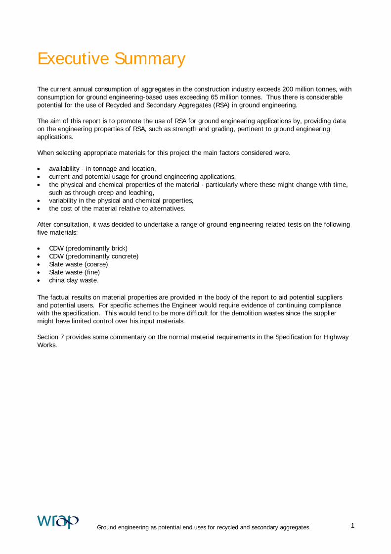
Executive Summary
The current annual consumption of aggregates in the construction industry exceeds 200 million tonnes, with consumption for ground engineering-based uses exceeding 65 million tonnes. Thus there is considerable potential for the use of Recycled and Secondary Aggregates (RSA) in ground engineering. The aim of this report is to promote the use of RSA for ground engineering applications by, providing data on the engineering properties of RSA, such as strength and grading, pertinent to ground engineering applications. When selecting appropriate materials for this project the main factors considered were. • availability - in tonnage and location, • current and potential usage for ground engineering applications, • the physical and chemical properties of the material - particularly where these might change with time,
such as through creep and leaching, • variability in the physical and chemical properties, • the cost of the material relative to alternatives. After consultation, it was decided to undertake a range of ground engineering related tests on the following five materials: • CDW (predominantly brick) • CDW (predominantly concrete) • Slate waste (coarse) • Slate waste (fine) • china clay waste.
The factual results on material properties are provided in the body of the report to aid potential suppliers and potential users. For specific schemes the Engineer would require evidence of continuing compliance with the specification. This would tend to be more difficult for the demolition wastes since the supplier might have limited control over his input materials. Section 7 provides some commentary on the normal material requirements in the Specification for Highway Works.
Ground engineering as potential end uses for recycled and secondary aggregates 1
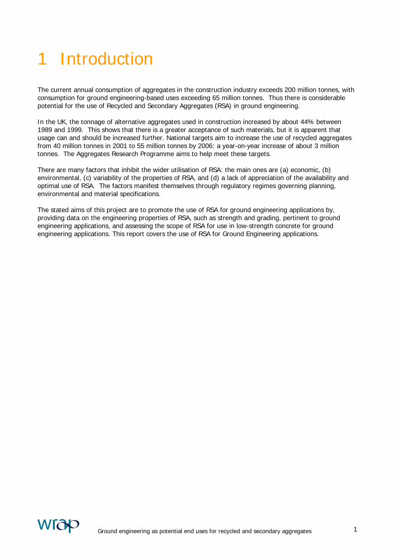
1 Introduction
The current annual consumption of aggregates in the construction industry exceeds 200 million tonnes, with consumption for ground engineering-based uses exceeding 65 million tonnes. Thus there is considerable potential for the use of Recycled and Secondary Aggregates (RSA) in ground engineering. In the UK, the tonnage of alternative aggregates used in construction increased by about 44% between 1989 and 1999. This shows that there is a greater acceptance of such materials, but it is apparent that usage can and should be increased further. National targets aim to increase the use of recycled aggregates from 40 million tonnes in 2001 to 55 million tonnes by 2006: a year-on-year increase of about 3 million tonnes. The Aggregates Research Programme aims to help meet these targets. There are many factors that inhibit the wider utilisation of RSA: the main ones are (a) economic, (b) environmental, (c) variability of the properties of RSA, and (d) a lack of appreciation of the availability and optimal use of RSA. The factors manifest themselves through regulatory regimes governing planning, environmental and material specifications. The stated aims of this project are to promote the use of RSA for ground engineering applications by, providing data on the engineering properties of RSA, such as strength and grading, pertinent to ground engineering applications, and assessing the scope of RSA for use in low-strength concrete for ground engineering applications. This report covers the use of RSA for Ground Engineering applications.
Ground engineering as potential end uses for recycled and secondary aggregates 1
2 Background
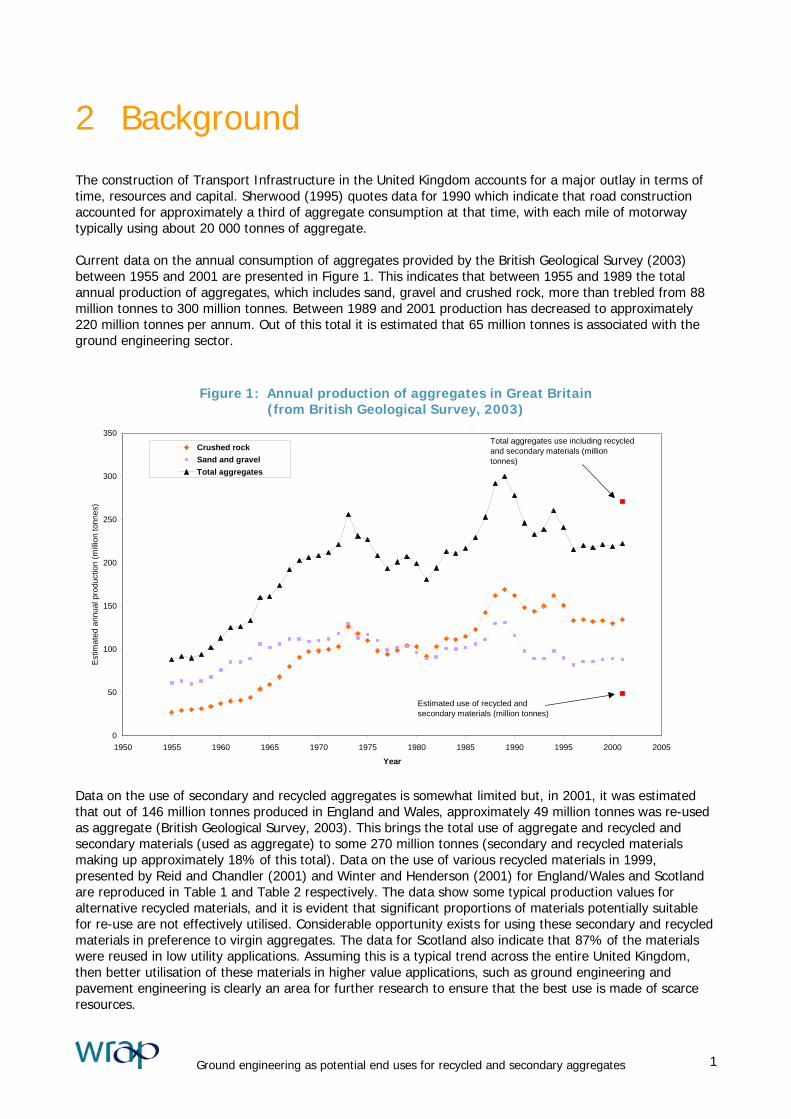
The construction of Transport Infrastructure in the United Kingdom accounts for a major outlay in terms of time, resources and capital. Sherwood (1995) quotes data for 1990 which indicate that road construction accounted for approximately a third of aggregate consumption at that time, with each mile of motorway typically using about 20 000 tonnes of aggregate. Current data on the annual consumption of aggregates provided by the British Geological Survey (2003) between 1955 and 2001 are presented in Figure 1. This indicates that between 1955 and 1989 the total annual production of aggregates, which includes sand, gravel and crushed rock, more than trebled from 88 million tonnes to 300 million tonnes. Between 1989 and 2001 production has decreased to approximately 220 million tonnes per annum. Out of this total it is estimated that 65 million tonnes is associated with the ground engineering sector.
Figure 1: Annual production of aggregates in Great Britain (from British Geological Survey, 2003)
0
50
100
150
200
250
300
350
1950 1955 1960 1965 1970 1975 1980 1985 1990 1995 2000 2005
Year
Est
imat
ed a
nnua
l pro
duct
ion
(milli
on to
nnes
)
Crushed rockSand and gravelTotal aggregates
Estimated use of recycled and secondary materials (million tonnes)
Total aggregates use including recycled and secondary materials (million tonnes)
Data on the use of secondary and recycled aggregates is somewhat limited but, in 2001, it was estimated that out of 146 million tonnes produced in England and Wales, approximately 49 million tonnes was re-used as aggregate (British Geological Survey, 2003). This brings the total use of aggregate and recycled and secondary materials (used as aggregate) to some 270 million tonnes (secondary and recycled materials making up approximately 18% of this total). Data on the use of various recycled materials in 1999, presented by Reid and Chandler (2001) and Winter and Henderson (2001) for England/Wales and Scotland are reproduced in Table 1 and Table 2 respectively. The data show some typical production values for alternative recycled materials, and it is evident that significant proportions of materials potentially suitable for re-use are not effectively utilised. Considerable opportunity exists for using these secondary and recycled materials in preference to virgin aggregates. The data for Scotland also indicate that 87% of the materials were reused in low utility applications. Assuming this is a typical trend across the entire United Kingdom, then better utilisation of these materials in higher value applications, such as ground engineering and pavement engineering is clearly an area for further research to ensure that the best use is made of scarce resources.
Ground engineering as potential end uses for recycled and secondary aggregates 1
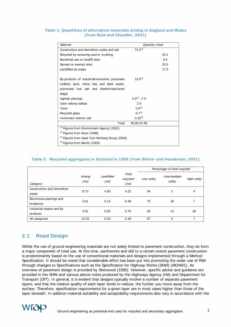
Table 1: Quantities of alternative materials arising in England and Wales (from Reid and Chandler, 2001)
Material Quantity (mta) Construction and demolition waste and soil 72.5(1)
Recycled by screening and/or crushing 25.1
Beneficial use on landfill sites 9.5
Spread on exempt sites 20.3
Landfilled as waste 17.5
By-products of industrial/extractive processes
(colliery spoil, china clay and slate waste,
pulverised fuel ash and blastfurnace/steel
slags)
15.0(2)
Asphalt planings 5.0(2) –7.0
Used railway ballast 2.0
Tyres 0.4(3)
Recycled glass 0.7(4)
Incinerator bottom ash 0.25(4)
Total 95.85-97.85 (1) Figures from Environment Agency (2001) (2) Figures from Anon (1998) (3) Figures from Used Tyre Working Group (2000) (4) Figures from Barritt (2000)
Table 2: Recycled aggregates in Scotland in 1999 (from Winter and Henderson, 2001)
Percentage of total recycled
Category
Arising (mt)
Landfilled (mt)
Total recycled
(mt)
It
Low utility ntermediate
u ilityHigh utility
Construction and Demolition
waste 8.73 4.50 4.22 94 2 4
Bituminous planings and
breakouts 0.61 0.14 0.48 75 18 7
Industrial wastes and by
products 0.91 0.55 0.79 59 13 28
All categories 10.25 5.20 5.49 87 5 7
2.1 Road Design Whilst the use of ground engineering materials are not solely limited to pavement construction, they do form a major component of total use. At this time, earthworks and still to a certain extent pavement construction is predominantly based on the use of conventional materials and designs implemented through a Method Specification. It should be noted that considerable effort has been put into promoting the wider use of RSA through changes to Specifications such as the Specification for Highway Works (SHW) (MCHW1). An overview of pavement design is provided by Sherwood (1995). However, specific advice and guidance are provided in the SHW and various advice notes produced by the Highways Agency (HA) and Department for Transport (DfT). In general, it is evident that designs typically involve a number of separate pavement layers, and that the relative quality of each layer tends to reduce, the further you move away from the surface. Therefore, specification requirements for a given layer are in most cases higher than those of the layer beneath. In addition material suitability and acceptability requirements also vary in accordance with the
Ground engineering as potential end uses for recycled and secondary aggregates 1
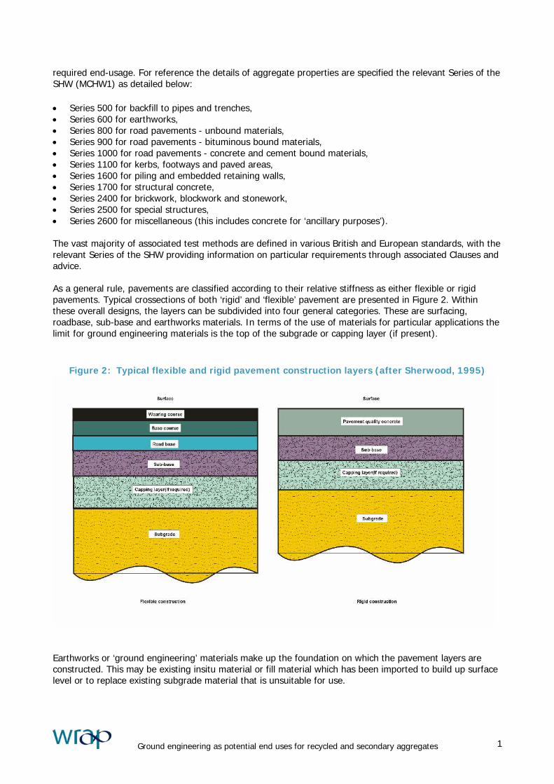
required end-usage. For reference the details of aggregate properties are specified the relevant Series of the SHW (MCHW1) as detailed below: • Series 500 for backfill to pipes and trenches, • Series 600 for earthworks, • Series 800 for road pavements - unbound materials, • Series 900 for road pavements - bituminous bound materials, • Series 1000 for road pavements - concrete and cement bound materials, • Series 1100 for kerbs, footways and paved areas, • Series 1600 for piling and embedded retaining walls, • Series 1700 for structural concrete, • Series 2400 for brickwork, blockwork and stonework, • Series 2500 for special structures, • Series 2600 for miscellaneous (this includes concrete for ‘ancillary purposes’). The vast majority of associated test methods are defined in various British and European standards, with the relevant Series of the SHW providing information on particular requirements through associated Clauses and advice. As a general rule, pavements are classified according to their relative stiffness as either flexible or rigid pavements. Typical crossections of both ‘rigid’ and ‘flexible’ pavement are presented in Figure 2. Within these overall designs, the layers can be subdivided into four general categories. These are surfacing, roadbase, sub-base and earthworks materials. In terms of the use of materials for particular applications the limit for ground engineering materials is the top of the subgrade or capping layer (if present).
Figure 2: Typical flexible and rigid pavement construction layers (after Sherwood, 1995)
Earthworks or ‘ground engineering’ materials make up the foundation on which the pavement layers are constructed. This may be existing insitu material or fill material which has been imported to build up surface level or to replace existing subgrade material that is unsuitable for use.
Ground engineering as potential end uses for recycled and secondary aggregates 1
The strength or ‘bearing capacity’ of the subgrade plays a vital role in the design and thickness of the road structure above it. The bearing capacity of earthworks materials is usually measured using the California Bearing Ratio (CBR) described in BS1377:1990. This is an empirical test that relates all materials against a good quality crushed rock, which is considered to have a bearing capacity of 100%. In terms of the layered approach to road construction the majority of earthworks materials can be split broadly into capping and general fill classifications. In addition, earthworks materials can also be used in a variety of other applications such as fill to structures and reinforced earth. These have various additional suitability and acceptability criteria. These criteria are specified to ensure that materials are appropriate for the use intended both in the short and long-term. 2.2 Specifications Within each of the Series highlighted above, materials are selected on the basis of their ability to fulfil various functional requirements. Compliance with these various requirements are implemented through appropriate specifications and advice for each application. For instance, within Series 600, a capping layer has two functions:
1) In the short term it acts as a working platform for construction of the sub base, and provides protection for weak subgrades.
-
2) Acts as a structural layer in the long term. (HA44, 1991).
In this instance, the SHW has three material classes for capping (6F1, 6F2 and 6F3) that define particular properties that act to ensure that these objectives are met for any proposed material. These include a general description of allowed and dis-allowed materials, method of compaction, particle size distribution, strength of particles, moisture content. The last of these is Class 6F3, which is specifically aimed at encouraging the use of recycled asphalt planed off the road. The Specification has been designed to use appropriate materials that are fit for purpose in each application. It is quite likely that the same source of material may be used in a variety of applications. Due to the large volume of materials required, this generally means using local available materials wherever possible and balancing cut and fill operations during construction. It is obvious that environmental benefits can be realised if in addition to natural materials the use of locally available RSA is encouraged. This project aims to encourage use of RSA by providing data on the laboratory performance of these materials in order to aid both the specifier and the end user.
Ground engineering as potential end uses for recycled and secondary aggregates 1

Table 3: Permitted uses of alternative materials in the Specification for Highway Works (Reid and Chandler, 2001)
Application & Series in SHW Specific provision in SHW
Permitted if complies with
SHW requirements Not permitted
Embankment and fill (Series 600)
Recycled concrete,
blastfurnace slag, burnt
colliery spoil, PFA, recycled
aggregate, asphalt
planings.
Unburnt colliery spoil,
spent oil shale, FBA, china
clay waste, slate waste.
Steel slag
Capping (Series 600) PFA, asphalt planings,
recycled aggregate
Recycled concrete,
blastfurnace slag, burnt
colliery spoil, spent oil
shale, FBA, china clay
waste, slate waste.
Steel slag, unburnt colliery
spoil
Unbound sub-base (Series 800)
Recycled concrete,
blastfurnace slag, steel
slag, burnt colliery spoil,
spent oil shale, recycled
aggregate, asphalt
planings.
China clay waste, slate
waste
Unburnt colliery spoil, PFA,
FBA, slate waste
Bitumen bound layers (Series 900)
Asphalt planings,
blastfurnace slag, steel
slag, recycled aggregate,
recycled concrete.
China clay waste
Burnt colliery spoil,
unburnt colliery spoil,
spent oil shale, PFA, FBA,
slate waste.
Cement bound sub-base (Series 1000)
Recycled concrete,
blastfurnace slag, recycled
aggregate.
Asphalt planings, steel
slag, burnt colliery spoil,
unburnt colliery spoil,
spent oil shale, PFA, FBA,
china clay waste, slate
waste.
None
Cement bound roadbase (Series 1000)
Recyled concrete,
blastfurnace slag, PFA,
recycled aggregate.
China clay waste, slate
waste.
Asphalt planings, steel
slag, burnt colliery spoil,
unburnt colliery spoil,
spent oil shale, FBA.
Pavement quality concrete (Series 1000)
Recycled concrete, blast
furnace slag, PFA, micro
silica
China clay waste, slate
waste.
Asphalt planings, steel
slag, burnt colliery spoil,
unburnt colliery spoil,
spent oil shale, FBA.
PFA = Pulverised fuel ash
FBA = Furnace bottom ash
Recycled aggregate is aggregate resulting from the processing of material used in a construction process
Ground engineering as potential end uses for recycled and secondary aggregates 1

3 Material Description
3.1 Material Selection When selecting appropriate materials for this project it was decided to focus on the practical, performance and environmental issues associated with the use of RSA for ground engineering applications. For maximum benefit, it was decided that the materials should be ‘reasonably typical’ of a range of RSA and also be available across England, therefore a number of materials were chosen from mainstream sources. The range of RSA is wide, and the engineering properties of them also vary widely. It was first necessary to select a few materials from the wide range of RSA available with choice being governed by: • availability - in tonnage and location, • current and potential usage for ground engineering applications, • the physical and chemical properties of the material - particularly where these might change with time,
such as through creep and leaching, • variability in the physical and chemical properties, • the cost of the material relative to alternatives. Data on the availability and consumption of candidate materials are provided in Table 4.
Table 4: Availability of typical RSA materials in England: from ODPM (2001)
Material Total arisings
(million tonnes)
Stockpiled
(million tonnes)
Available for use as aggregate
(million tonnes)
CDW 88.9 - 36.5
China clay waste 22.6 72.5 2.3
Colliery spoil 7.3 13.0 0.8
Slate waste 2.3 3.5 0.3
PFA 4.4 50.0 1.5
Total 125.5 139.0 41.5
3.1.1 Candidate materials Construction Demolition Waste (CDW) Construction demolition waste is widely used by the construction industry as a bulk fill; for example, for filling voids, foundations and as capping layers to highways. This type of material is produced continuously and there seems to be scope for increasing its usage. This type of material represents, typically, a coarse-grained backfill. Because of the variability in this type of waste it was proposed to sample and test two sources of CDW - one containing a significant percentage of brick rubble and one formed (predominantly) from crushed concrete. It was proposed to undertake tests to determine the engineering properties of the coarse fractions of these two materials. China clay waste Substantial quantities of china clay waste exist in Cornwall and Devon, and the owners of the quarries (‘Imerys’) are committed to extracting china clay for a further 40 years or so. This material has been used for road building works in and around the stockpiles. Although the geographical distribution of the material is rather limited, the material can be exported from its location by rail or sea and represents a typical inert sand-sized material as might be found in other quarries for natural aggregates. This waste has potential for use for ground engineering applications and for low-strength concrete.
Ground engineering as potential end uses for recycled and secondary aggregates 1

Slate waste Although the largest deposits of slate waste in the UK are found in Wales, substantial quantities exist in Cumbria and Cornwall. It is expected that further quantities of the waste will be produced over the next 20 years or so. The slate waste is available in different fraction sizes. In terms of the testing for this project it was proposed to test the coarse-grained fraction for use as construction fill, and investigate the use of a finer grading for use in low-strength concrete. Pulverised Fuel Ash Substantial stocks of pulverized fuel ash (PFA) are available in many parts of England, and the material has been widely used for constructing road embankments and as a filler/additive to cement. There is already substantial literature on the properties of this material, and specifications for its use as a general fill already exist; for example, as given in Table 6/1 of Volume 1 of the SHW. Whilst the properties of PFA are well researched, because of the variable nature of the material, it is not possible to give ‘typical’ values for its engineering properties. Although it may be wise to investigate the use of PFA as a binder, in combination with cement, to fine-grained waste materials in future research. 3.1.2 Selected materials After consultation, it was decided to undertake a range of ground engineering related tests on the following five materials: • CDW (predominantly brick), • CDW (predominantly concrete) • Slate waste (coarse) • Slate waste (fine) • china clay waste. 3.2 Material collection Following selection, samples of the various materials were obtained from identified sources. For each of the materials these are described in the following text. CDW (brick) The sample of CDW (brick) required for the project, was obtained from Stockton Quarry near Middlesbrough, owned by RMC Aggregates Northern. This consisted of a bulk sample sourced from a single stock pile of crushed CDW. This material was generated from demolition activities in the local area and transported to the quarry for crushing. The operator of the facility estimated an approximate brick content of 40%. CDW (concrete) The CDW (concrete) sample was obtained from J Moulds Demolition limited near Reading. On site they had three main stockpiles. These consisted of a material termed one ‘Type 1 sub-base’, concrete all in crusher run (some larger lumps – about 100 or 125 mm cube and lots of fines) Also a ‘part brick’ all in crusher run similar to the concrete but with some brick visible in the mix. For the main sample CDW sample the ‘Type 1’ material was sampled. In addition further samples were taken from the stockpiles. One sample consisted of a material with a finer grading which was taken for Particle size analysis. Slate waste Bulk samples of Slate waste (both coarse and fine) were sourced from Mill Hill Quarry near Tavistock. These samples consisted of a coarse sized fraction and a fine fraction, referred to as ‘dust’. Unfortunately, only single stockpiles of the materials were available at the time of collection, therefore samples of other stockpiles were not able to be taken. China Clay waste
Ground engineering as potential end uses for recycled and secondary aggregates 1
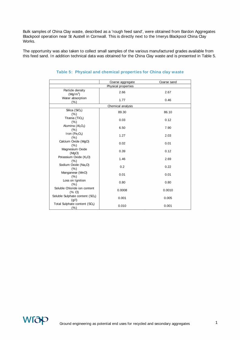
Bulk samples of China Clay waste, described as a 'rough feed sand', were obtained from Bardon Aggregates Blackpool operation near St Austell in Cornwall. This is directly next to the Imerys Blackpool China Clay Works. The opportunity was also taken to collect small samples of the various manufactured grades available from this feed sand. In addition technical data was obtained for the China Clay waste and is presented in Table 5.
Table 5: Physical and chemical properties for China clay waste
Coarse aggregate Coarse sand Physical properties
Particle density (Mg/m3) 2.66 2.67
Water absorption (%) 1.77 0.46
Chemical analysis Silica (SiO2)
(%) 89.30 86.10
Titania (TiO2) (%) 0.03 0.12
Alumina (Al2O3) (%) 6.50 7.90
Iron (Fe2O3) (%) 1.27 2.03
Calcium Oxide (MgO) (%) 0.02 0.01
Magnesium Oxide (MgO) 0.39 0.12
Potassium Oxide (K2O) (%) 1.46 2.69
Sodium Oxide (Na2O) (%) 0.2 0.22
Manganese (MnO) (%) 0.01 0.01
Loss on Ignition (%) 0.80 0.80
Soluble Chloride ion content (% Cl) 0.0008 0.0010
Soluble Sulphate content (SO3) (g/l) 0.001 0.005
Total Sulphate content (SO3) (%) 0.010 0.001
Ground engineering as potential end uses for recycled and secondary aggregates 1
4 Laboratory Test Programme
Due to the large number of material classes within the SHW, each with there own suitability and acceptability criteria, it was necessary to devise a test programme that encompassed the main properties required for ground engineering materials. This test programme is presented in Table 6. Whilst this covers a large number of the properties required, for compliance with appropriate suitability and acceptability criteria, in the SHW it does not cover every eventuality. Numerous other tests are undertaken on aggregates used for ground engineering applications. However, most of these tests are not essential, and to keep the test programme within reasonable bounds it was decided not to undertake these tests as part of this phase of the project. These tests could be undertaken in follow-up work. Other applicable tests for future work may include, • Resistivity and redox tests - these are undertaken to assess the likelihood of microbiological attack. • Petrographic analysis – may be relevant data on slate waste and china clay waste should be available
from their suppliers, and analysis should not be required for the CDW. • Polished stone value – although the selected materials are unlikely to be used in any type of wearing
course. • Drying shrinkage - this is only relevant for bound materials, and should be covered by follow-up work on
low-strength concrete. • In situ tests - these site-specific tests could form part of a field study of the use of a particular RSA. • Those used to assess the use of the RSA for cement and/or lime-stabilisation. • Frost-susceptibility tests - it is essential that load-bearing materials placed within about 600mm of the
ground are not degraded by the effects of frost. Frost-susceptible materials tend to have a preponderance of silt-sized materials and so it should not be necessary to undertake tests on the selected RSA. (Such tests are costly to undertake and the results can vary widely.)
Ground engineering as potential end uses for recycled and secondary aggregates 1

Table 6: Laboratory test programme for selected RSA materials
CDW Brick
CDW Concrete
Slate waste (coarse)
Slate waste (fine) China Clay waste
Moisture content
Particle density
Particle size distribution
Flakiness index -
Permeability
Shear box tests
Stiffness
10% fines
Particle soundness
Compaction test
CBR
p H
Organic content Inspection only
Sulfur content (series of tests)
Chloride content
Ground engineering as potential end uses for recycled and secondary aggregates 1

5 Laboratory Testing
Samples of the selected materials were collected from the various sources. The following sections provide information on selected test methods and specific information with regard to actual test procedures adopted. 5.1 Moisture content This most important characteristic determines the suitability of many materials for use as a general fill materials. In order to ascertain the variability of the material. Moisture contents samples were taken from a number of different locations within the same source. These tests were carried out in accordance with BS 1377: Part 2: Method 3.2 (1990). In keeping with convention, moisture content is expressed in terms of the percentage of the dry weight of the material. 5.2 Particle density The particle density, or specific gravity, is a fundamental property of any material. A value is required to convert volume to weight and vice versa, and is also necessary to determine the air voids content of a compacted specimen. Particle density tests were conducted on each of the selected materials in accordance with BS1377: Part 2: Method 8.2 (1990). 5.3 Particle size distribution The grading of each of the five materials was determined using a dry and/or wet-sieving technique, as deemed appropriate. These tests were carried out in accordance with BS1377: Part 2: Methods 9.2 (dry) or 9.3 (wet) (1990). Typically the selection of the type of test depends upon the size and quantity of fine grains in the material. Given the choice of RSA materials, which were predominantly granular in nature, it was deemed that sedimentation tests to define clay content were not required for any of the selected materials. 5.4 Laboratory compaction tests Standard compaction tests are undertaken to determine the relation between moisture content and dry density. This relation defines the optimum moisture content (OMC) and maximum dry density (MDD) of a material, which can be used to assess and control the compaction operations on site. In terms of the compaction test methods available (2.5kg rammer, 4.5kg rammer and vibrating hammer). It was decided that the ‘vibrating hammer’ method of compaction was the most appropriate test for each of the five selected RSA materials. Therefore, Laboratory compaction tests were carried out in accordance with BS1377: Part 4: Method 3.7 (1990), (vibrating hammer) to determine the OMC, MDD and 95% ‘relative compaction’ of each material. Relative compaction being defined as the percentage of the maximum dry density determined via the appropriate laboratory compaction test on the same material (Parsons, 1992). Within the SHW it is usual to specify material acceptability criteria in terms of achieved states of compaction, through the application of an ‘end product’ criterion in terms of relative compaction, and/or in terms of as placed moisture content. Where no end product criteria is specified compaction is usually carried out in accordance with the appropriate method described in Table 6/4 of the SHW. For each set of tests on the five RSA materials determinations were carried out on separate sub-samples, so as to avoid problems due to crushing of particles.
Ground engineering as potential end uses for recycled and secondary aggregates 1
5.5 Laboratory CBR tests The California Bearing Ratio (CBR) value of a soil or aggregate is commonly used to design the lower layers of a highway pavement. In essence the CBR value is the resistance developed by a material for a specific depth of penetration of a standard-sized plunger. Although the use of a CBR value is restricted, by and large, to the design of pavements it provides a good means of comparing the properties of different soils and fills. This is largely because CBR values are widely quoted in relevant literature and understood by engineers. Therefore, Laboratory CBR tests were carried out in accordance with BS1377: Part 4: Method 3.7 (BSI, 1990). Sample preparation was undertaken, for each of the materials, using the vibrating hammer compaction method, at a range of moisture contents. For the finer grained materials, CBR values were measured on samples compacted during the laboratory compaction test. For the coarser grained materials, CDW (brick), CDW (concrete) and coarse slate, separate samples were compacted using material passing a 20mm sieve. For comparison a number of laboratory compaction test samples were also tested. These samples were slightly coarser containing material passing a 37.5mm test sieve, as opposed to the 20mm limit specified for CBR testing in BS 1377. 5.6 Crushing strength (10% fines test) It is clearly important that an aggregate has sufficient strength to resist the forces that will be applied to it in-service. Therefore, the crushing strength of each material was determined through a 10%-fines test. This test measures the load required to generate 10% fines from a particular size range of material. These tests were carried out by an outside test house in accordance with BS 812: Part 111: (1990). The test is typically undertaken on a narrow band of particle sizes, usually between 10 and 14mm. However, due to the grading of the fine slate waste, the test was undertaken in the particle range between 6.3 and 10mm. 5.7 Shear strength tests The shear strength of a granular material is usually determined by its initial placement density and the level of applied normal stress. In some cases, strength can also be influenced by a number of factors, including the rate of shear, initial moisture content, the presence of cohesive fines, the method used to form the specimen, and the crushing strength of the particles. It is, therefore, necessary to define carefully both the preparation and test conditions to limit the number of tests required and to ensure that the data are of value to an engineer. Therefore, shearbox tests were carried out according to BS1377: Part 7: Method 5.0: 1990, using an 300 by 300mm direct shearbox apparatus. These tests were carried out with a selected rate of shear of 1.016mm/min. 5.7.1 Standard shear strength testing regime For each of the five selected materials, a set of three shear tests were carried out. These were conducted over a range of normal stresses. This range of stresses was selected to simulate overburdens approximately equivalent to the maximum vertical pressures at the base, quarter and mid-height of a five metre high embankment, i.e. 100, 75 and 50kPa respectively. In addition one further test was conducted for each material. This involved the placement of loose material in the shearbox apparatus and tested at a normal stress equivalent to that at the bottom of a five metre high embankment (100kPa). For the first set of three tests, the samples were prepared to a high density (HD). The test specimens were compacted in three approximately equal layers using a vibrating hammer. Each layer was compacted so that each sixth of the surface area of the layer was under compaction for sixty seconds, i.e. a total of six minutes
Ground engineering as potential end uses for recycled and secondary aggregates 1
per layer. This would typically achieve states of compaction at, or above, the MDD values obtained from a laboratory vibrating hammer compaction test. As such, the results of these tests would indicate the highest shear strength typically achievable on site under good conditions i.e. with a material at, or close to, OMC and efficient compaction plant. For the additional test, the specimen was placed loosely in the shearbox to a low density (LD). This test was undertaken to facilitate the confirmation of residual shear strength and provide a direct measurement of the critical state angle of friction. Both HD and LD test sets were carried out using material from the same bulk sample. All the bulk samples comprised of material passing a 37.5mm BS test sieve. 5.8 Permeability In a great many ground engineering applications, the aggregate should be effectively free-draining. Particular examples include; when a material is placed immediately behind the back of a retaining wall or buried structure and, not surprisingly, when used as part of a drainage system. Such a requirement is not necessary for ‘non-structural’ filling, such as when constructing an embankment. The permeability of an aggregate can be estimated from its grading curve and permeability tests are not usually required or undertaken on coarse-grained materials. However, it is important to measure the permeability of fine-graded soils such as silty sands and soils prone to crushing by construction plant during placement. Therefore, permeability tests were only deemed appropriate for the fine grained materials i.e. china clay waste and fine slate waste. These were conducted on well-compacted and poorly-compacted specimens and in accordance with the procedure described in BS1377: Part 5: 1990 using the constant head method. 5.9 Flakiness index For some end-uses, specifications limit the amount of flaky particles that can be accepted for an aggregate (see, for example, Clause 919 of Volume 1 of the SHW). This is primarily because flaky particles tend to; • crush under applied loads, • interfere with the packing of particles, thereby preventing the attainment of a low air void content on
compaction, • require a relatively high water-binder ratio or binder content in a bound material. In general, a visual inspection is carried out to assess whether or not a test is required. In the case of the materials selected for this project it was deemed that the coarse slate material was the only applicable material. Therefore, flakiness index testing was carried out in accordance with BS 812 Part 105: Section 105.1: 1989, for this material only. 5.10 Stiffness (bulk modulus) The ‘stiffness’ or ‘modulus of reaction’ M* of a material can be used to assess the compression resulting from the application of a normal load. This can be an important consideration in some applications. For instance it affects the deflection of the surfacing of a pavement or car park to vehicle loads, and the settlement of a foundation to a building, or the structural support that a fill material provides to a buried structure, such as a pipe or culvert. In only a few applications is it necessary to measure the stiffness of primary granular soils and aggregates, but it is often required of RSA because they are, commonly, formed of particles which have a relatively low crushing strength. One application is the use of aggregate as fill to a buried structure where a minimum value of the ‘constrained modulus’ is required to ensure that the material provides sufficient structural
Ground engineering as potential end uses for recycled and secondary aggregates 1
support to the structure (see Clause 642 of Volume 1 of the SHW). In that Clause the constrained modulus is derived from the results of plate bearing tests or standard penetration tests: neither of which are particularly suitable for this project. The Clause allows the use of one-dimensional consolidation tests for undisturbed specimens of cohesive soils. Only a few organisations have access to large test equipment suitable for testing granular soils: TRL has a 0.5m diameter compression cell and have used this to characterise the stiffness of a coarse-grained limestone backfill, see for example Brady and Kirk (1990). Although this equipment could be used to determine the compressibility of the RSA the cost of completing a suite of tests is rather high; but the cost may be justified for a particular application. Thus an alternative, cheaper method of measuring stiffness is proposed. A specimen will be prepared as required for undertaking a laboratory CBR test (see below) and a load will be applied, in four increments, across the whole cross-section of the specimen up to a maximum of 500kN/m2. Although this is not a standard laboratory test, it is a readily understandable technique and so the results can be used with some confidence. The relation between load and deflection will be used to derive a value for the constrained modulus of the material for the various load levels. Note that the total compression of the material derives from the rearrangement and crushing of the particles (see below). The standard methods for assessing crushing strength are not particularly suited for mixed materials, and so these tests provide useful information on the total compressibility of the graded RSA. 5.11 Particle Soundness The measurement of particle soundness can give an indication as to the durability of a material. In respect of facilitating the wider take-up of RSA concerns about durability are a barrier, particularly for the use of RSA in concrete products. It should be appreciated that in some cases such concerns are justified. Whilst, there are a number of standard tests for assessing soundness, including the magnesium sulfate soundness test and the point load test. In terms of initial assessment, magnesium sulfate tests were undertaken in accordance with BS 812: Part 121: (1989) on samples of each of the five RSA materials. 5.12 Chemical and other tests pH The measurement of pH is one of a number of standard tests devised to check the aggressivity of aggregate to steel and concrete structures. The pH of the materials were determined in accordance with BS1377: Part 3: Method 9 (1990), by an outside test house. Organic content Aggregates having a substantial organic content are not used for structural purposes or for manufacturing concrete products. This is because the organic matter adversely affects the engineering properties of a fill and can retard the setting of concrete. The organic content was assessed by the ‘loss on ignition test. However, determining the organic content of an aggregate is not straightforward, and contamination of a specimen and errors in test procedures can exaggerate the organic content. Thus each of the materials was also inspected visually for the presence of organic contamination prior to any test. Sulfur content TRL have recently completed a project for the HA to examine the reliability of current standard methods for quantifying and reporting the concentration of sulfur compounds in materials. Reid et al (2001) has reported some of the results of this study. This work has led to improvements in test techniques, and consistency in the reporting of the results. Changes in the HA specifications and the current British standards have either been put in place already or are about to follow. It is proposed to carry out the suite of tests to determine the total sulfur, soluble sulfur and sulphide contents of the selected RSA. Chloride content In order to ensure that a fill material will not be harmful to steel or concrete structures, such as retaining walls or corrugated buried steel structures. The chloride content of fill material is routinely measured to
Ground engineering as potential end uses for recycled and secondary aggregates 1
ensure that it is below levels that cause long-term deterioration. Each of the materials was tested in accordance with BS1377: Part 3: Method 7 (1990), by an external test house. Plasticity index Taken together, the plastic and limit limits of a material provide a good indicator of its sensitivity of the physical properties (strength and stiffness, for example) to a change in moisture content. Whilst it is improbable that it will be necessary to carry out tests to determine these limits, for these granular materials, the fine fraction off the RSA was checked to see that it was non plastic.
Ground engineering as potential end uses for recycled and secondary aggregates 1

6 Laboratory results
6.1 Moisture content The results of initial moisture content tests on the bulk samples of each of the selected materials are presented in Table 7. In general terms most of the materials were consistent with little variability although the CDW (brick) samples did range between 7.6% and 11%. Generally materials are required near the optimum moisture content, to ensure good compaction and material can be spread out to dry or be wetted up by water spray to achieve this.
Table 7: Moisture contents of initial bulk samples
Moisture content (%)
Average
moisture content
(%)
Sample ID A B C
CDW (brick) 11.0 7.6 8.1 8.9
CDW (concrete) 2.0 2.1 1.8 5.9
Slate waste
(coarse) 1.8 2.0 2.3 2.0
Slate waste
(fine)
1.1
(only one small stockpile available) 1.1
China clay waste 6.1 6.4 6.0 6.2
6.2 Particle density The results of Particle density testing for each of the five selected materials are presented in Table 8. As would be expected, both slate waste materials had high particle densities of 2.82Mg/m3. Whilst the CDW (brick) sample had the lowest at 2.51Mg/m3. The results for CDW (concrete) and the china clay waste were broadly in line with those typically expected for these types of material.
Table 8: Particle density data for selected RSA materials
Material
Particle density
(Mg/m3)
CDW (brick) 2.51
CDW (concrete) 2.58
Slate waste (coarse) 2.82
Slate waste (fine) 2.82
China clay waste 2.68
Ground engineering as potential end uses for recycled and secondary aggregates 1

6.3 Particle size distribution The results of particle size analysis for each of the five materials are presented in Figure 3, Figure 4, Figure 5, Figure 6 and Figure 7 for the CDW (brick), CDW (concrete), coarse slate, fine slate and china clay waste respectively. The associated uniformity coefficients for the materials are presented in Table 9. The results of these gradings are also presented, in terms of compliance with grading and uniformity coefficient requirements in Series 600 of the SHW (MCHW1: Table 6/2), in table 10 and
Ground engineering as potential end uses for recycled and secondary aggregates 1
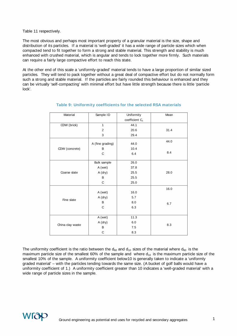
Table 11 respectively. The most obvious and perhaps most important property of a granular material is the size, shape and distribution of its particles. If a material is ‘well-graded’ it has a wide range of particle sizes which when compacted tend to fit together to form a strong and stable material. This strength and stability is much enhanced with crushed material, which is angular and tends to lock together more firmly. Such materials can require a fairly large compactive effort to reach this state. At the other end of this scale a ‘uniformly-graded’ material tends to have a large proportion of similar sized particles. They will tend to pack together without a great deal of compactive effort but do not normally form such a strong and stable material. If the particles are fairly rounded this behaviour is enhanced and they can be virtually ‘self-compacting’ with minimal effort but have little strength because there is little ‘particle lock’.
Table 9: Uniformity coefficients for the selected RSA materials
Material Sample ID Uniformity
coefficient Cu
Mean
CDW (brick) 1
2
3
44.1
20.6
29.4
31.4
44.0
CDW (concrete)
A (fine grading)
B
C
44.0
10.4
6.4 8.4
Coarse slate
Bulk sample
A (wet)
A (dry)
B
C
26.0
37.8
25.5
25.5
25.0
28.0
16.0
Fine slate
A (wet)
A (dry)
B
C
16.0
5.7
8.0
6.3 6.7
China clay waste
A (wet)
A (dry)
B
C
11.3
6.0
7.5
8.3
8.3
The uniformity coefficient is the ratio between the d60 and d10 sizes of the material where d60 is the maximum particle size of the smallest 60% of the sample and where d10 is the maximum particle size of the smallest 10% of the sample. A uniformity coefficient below10 is generally taken to indicate a ‘uniformly graded material’ – with the particles tending towards the same size. (A bucket of golf balls would have a uniformity coefficient of 1.) A uniformity coefficient greater than 10 indicates a ‘well-graded material’ with a wide range of particle sizes in the sample.
Ground engineering as potential end uses for recycled and secondary aggregates 1

Table 10: Compliance with Table 6/2 (Grading requirements for Earthworks Materials)
SHW Class CDW (Brick) CDW (Concrete) Coarse slate Fine slate China clay waste
1A Y Y Y Y Y
1B Y Y Y Y Y
1C N N N N N
2A & 2B N N N N N
2C N N N Y N
2D N N N Y N
6A Y Y Y B B
6B N N N N N
6C N N N N N
6D N N N B N
6E & 6R Y N (fine psd
complied B Y Y
6F1 Y N (fine psd
complied) B N Y
6F2 B Y B N N
6F3 B Y B N N
6H N N N Y N
6I & 6J Y N B Y Y
6K N N N Y B
6L N N N B N
6M Y Y Y Y Y
6N & 6P Y Y Y Y Y
7A N N N N N
7C N N N N N
7D N N N N N
7E N N N N N
7F N N N N N
7I N N N N N
Notes:
Y = Yes, N = No , B = Borderline fail
It should also be noted that this Table only indicates compliance with the highlighted property. Other criteria, such as material
composition may preclude the use of the material in certain cases.
Ground engineering as potential end uses for recycled and secondary aggregates 1
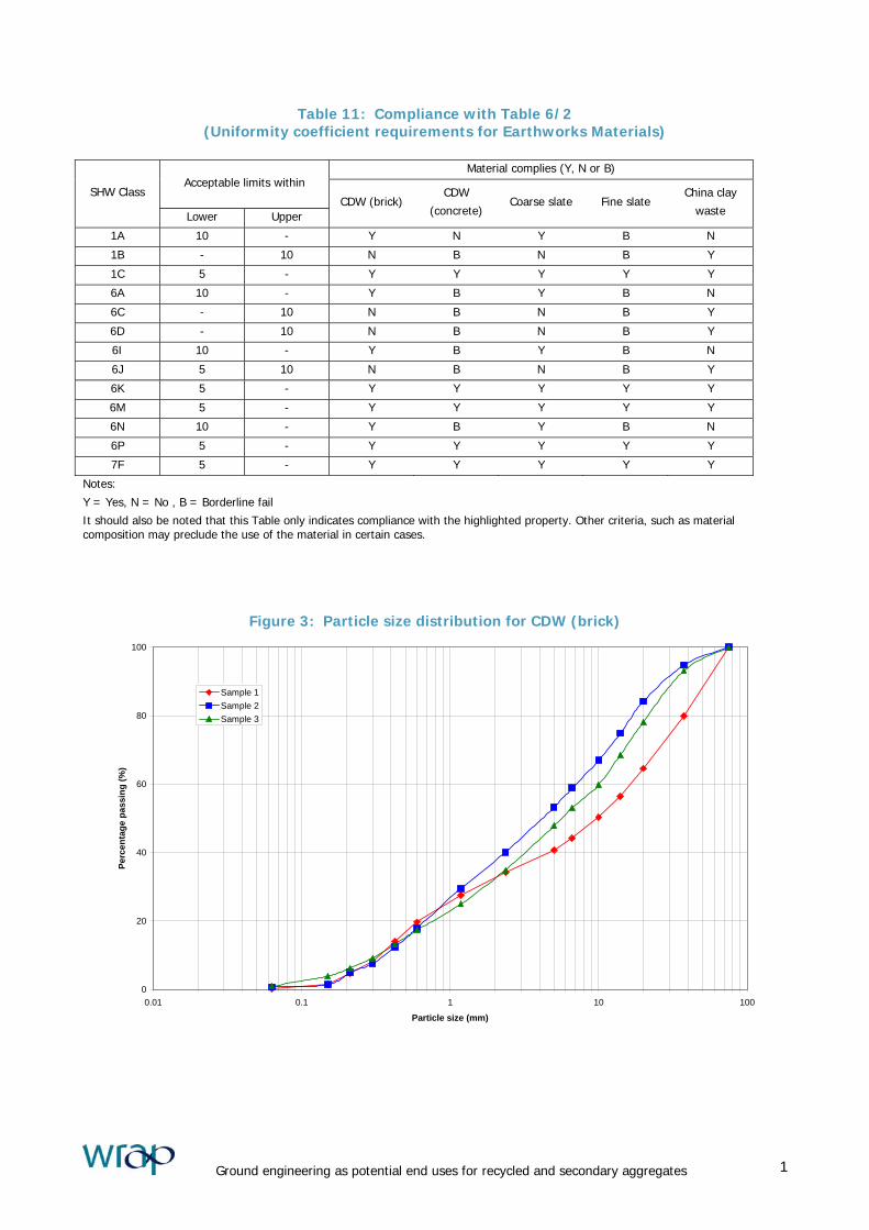
Table 11: Compliance with Table 6/2 (Uniformity coefficient requirements for Earthworks Materials)
Material complies (Y, N or B)
Acceptable limits within SHW Class
Lower Upper CDW (brick)
CDW
(concrete) Coarse slate Fine slate
China clay
waste
1A 10 - Y N Y B N
1B - 10 N B N B Y
1C 5 - Y Y Y Y Y
6A 10 - Y B Y B N
6C - 10 N B N B Y
6D - 10 N B N B Y
6I 10 - Y B Y B N
6J 5 10 N B N B Y
6K 5 - Y Y Y Y Y
6M 5 - Y Y Y Y Y
6N 10 - Y B Y B N
6P 5 - Y Y Y Y Y
7F 5 - Y Y Y Y Y
Notes:
Y = Yes, N = No , B = Borderline fail
It should also be noted that this Table only indicates compliance with the highlighted property. Other criteria, such as material composition may preclude the use of the material in certain cases.
Figure 3: Particle size distribution for CDW (brick)
0
20
40
60
80
100
0.01 0.1 1 10 100
Particle size (mm)
Perc
enta
ge p
assi
ng (%
)
Sample 1Sample 2Sample 3
Ground engineering as potential end uses for recycled and secondary aggregates 1

Figure 4: Particle size distribution for CDW (concrete)
0
20
40
60
80
100
0.01 0.1 1 10 100
Particle size (mm)
Perc
enta
ge p
assi
ng (%
)
Sample A (fine grading)Sample BSample C
Figure 5: Particle size distribution for slate waste (coarse)
0
20
40
60
80
100
0.01 0.1 1 10 100
Particle size (mm)
Perc
enta
ge p
assi
ng (%
)
Bulk sampleSample A (wet seive)Sample A (dry seive)Sample BSample C
Ground engineering as potential end uses for recycled and secondary aggregates 1
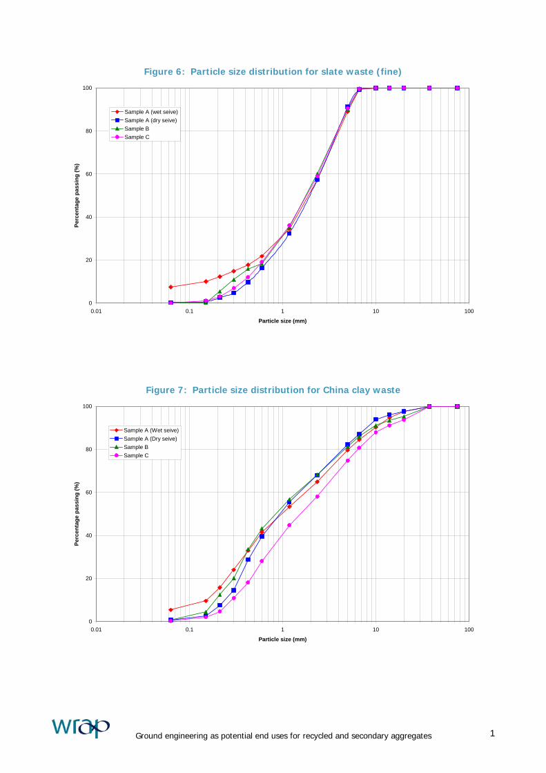
Figure 6: Particle size distribution for slate waste (fine)
0
20
40
60
80
100
0.01 0.1 1 10 100
Particle size (mm)
Perc
enta
ge p
assi
ng (%
)
Sample A (wet seive)Sample A (dry seive)Sample BSample C
Figure 7: Particle size distribution for China clay waste
0
20
40
60
80
100
0.01 0.1 1 10 100
Particle size (mm)
Perc
enta
ge p
assi
ng (%
)
Sample A (Wet seive)Sample A (Dry seive)Sample BSample C
Ground engineering as potential end uses for recycled and secondary aggregates 1
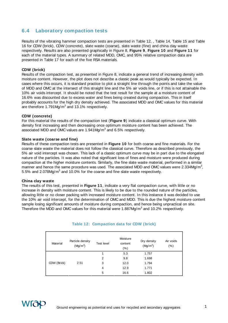
6.4 Laboratory compaction tests Results of the vibrating hammer compaction tests are presented in Table 12, , Table 14, Table 15 and Table 16 for CDW (brick), CDW (concrete), slate waste (coarse), slate waste (fine) and china clay waste respectively. Results are also presented graphically in Figure 8, Figure 9, Figure 10 and Figure 11 for each of the material types. A summary of related MDD, OMC, and 95% relative compaction data are presented in Table 17 for each of the five RSA materials. CDW (brick) Results of the compaction test, as presented in Figure 8, indicate a general trend of increasing density with moisture content. However, the plot does not describe a classic peak as would typically be expected. In cases where this occurs, it is standard practice to plot a straight line through the points and take the value of MDD and OMC at the intersect of this straight line and the 5% air voids line, or if this is not attainable the 10% air voids intercept. It should be noted that the test result for the sample at a moisture content of 16.6% was discounted due to excess water and fines being created during compaction. This in itself probably accounts for the high dry density achieved. The associated MDD and OMC values for this material are therefore 1.791Mg/m3 and 13.1% respectively. CDW (concrete) For this material the results of the compaction test (Figure 9) indicate a classical optimum curve. With density first increasing and then decreasing once optimum moisture content has been achieved. The associated MDD and OMC values are 1.941Mg/m3 and 6.5% respectively. Slate waste (coarse and fine) Results of these compaction tests are presented in Figure 10 for both coarse and fine materials. For the coarse slate waste the material does not follow the classical curve. Therefore as described previously, the 5% air void intercept was chosen. This lack of a classic optimum curve may be in part due to the elongated nature of the particles. It was also noted that significant loss of fines and moisture were produced during compaction at the higher moisture contents. Similarly, the fine slate waste material, performed in a similar manner and hence the same procedure was used. The associated MDD and OMC values were 2.334Mg/m3, 5.5% and 2.078Mg/m3 and 10.0% for the coarse and fine slate waste respectively. China clay waste The results of this test, presented in Figure 11, indicate a very flat compaction curve, with little or no increase in density with moisture content. This is likely to be due to the rounded nature of the particles, allowing little or no closer packing with increased moisture content. In this instance it was decided to use the 10% air void intercept, for the determination of OMC and MDD. This is due the highest moisture content sample losing significant amounts of moisture during compaction, and hence being unpractical on site. Therefore the MDD and OMC values for this material were 1.887Mg/m3 and 10.2% respectively.
Table 12: Compaction data for CDW (brick)
Material
Particle density
(Mg/m3)
Test level
Moisture
content
(%)
Dry density
(Mg/m3)
Air voids
(%)
1 5.3 1.757
2 9.8 1.698
3 12.0 1.794
4 12.9 1.771
CDW (Brick) 2.51
5 16.6 1.802
Ground engineering as potential end uses for recycled and secondary aggregates 1
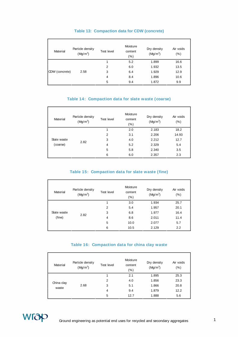
Table 13: Compaction data for CDW (concrete)
Material
Particle density
(Mg/m3)
Test level
Moisture
content
(%)
Dry density
(Mg/m3)
Air voids
(%)
1 5.2 1.899 16.6
2 6.0 1.932 13.5
3 6.4 1.929 12.9
4 8.4 1.896 10.6
CDW (concrete) 2.58
5 9.4 1.872 9.9
Table 14: Compaction data for slate waste (coarse)
Material
Particle density
(Mg/m3)
Test level
Moisture
content
(%)
Dry density
(Mg/m3)
Air voids
(%)
1 2.0 2.183 18.2
2 3.1 2.206 14.93
3 4.0 2.212 12.7
4 5.2 2.329 5.4
5 5.8 2.340 3.5
Slate waste
(coarse) 2.82
6 6.0 2.357 2.3
Table 15: Compaction data for slate waste (fine)
Material
Particle density
(Mg/m3)
Test level
Moisture
content
(%)
Dry density
(Mg/m3)
Air voids
(%)
1 3.0 1.934 25.7
2 5.4 1.957 20.1
3 6.8 1.977 16.4
4 8.6 2.011 11.4
5 10.0 2.077 5.7
Slate waste
(fine) 2.82
6 10.5 2.129 2.2
Table 16: Compaction data for china clay waste
Material
Particle density
(Mg/m3)
Test level
Moisture
content
(%)
Dry density
(Mg/m3)
Air voids
(%)
1 2.1 1.895 25.3
2 4.0 1.856 23.3
3 5.1 1.866 20.8
4 9.4 1.879 12.2
China clay
waste 2.68
5 12.7 1.888 5.6
Ground engineering as potential end uses for recycled and secondary aggregates 1
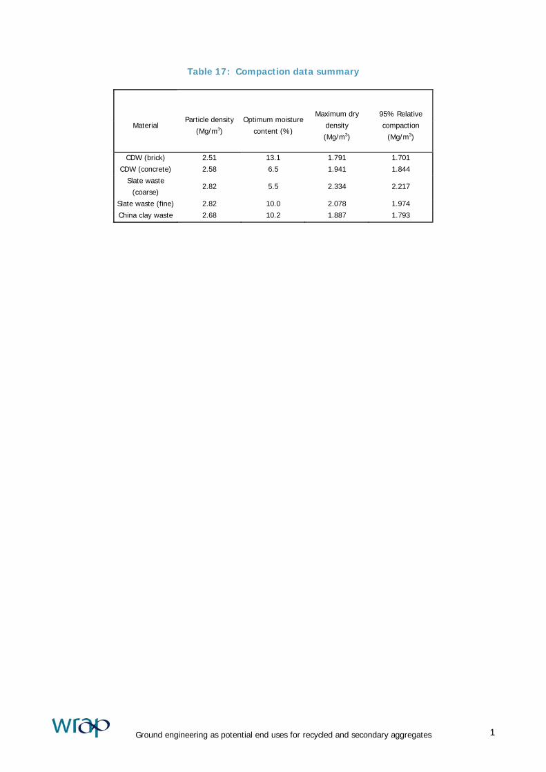
Table 17: Compaction data summary
Material
Particle density
(Mg/m3)
Optimum moisture
content (%)
Maximum dry
density
(Mg/m3)
95% Relative
compaction
(Mg/m3)
CDW (brick) 2.51 13.1 1.791 1.701
CDW (concrete) 2.58 6.5 1.941 1.844
Slate waste
(coarse) 2.82 5.5 2.334 2.217
Slate waste (fine) 2.82 10.0 2.078 1.974
China clay waste 2.68 10.2 1.887 1.793
Ground engineering as potential end uses for recycled and secondary aggregates 1

Figure 8: Vibrating hammer test results for CDW (brick)
1.600
1.700
1.800
1.900
2.000
2.100
2.200
2.300
2.400
0 2 4 6 8 10 12 14 16 18
Moisture content (%)
Dry
den
sity
Mg/
m3
CDW (brick)
0% air voids
5% air voids
10% air voids
20% air voids
Particle density = 2.51 Mg/m3
Ground engineering as potential end uses for recycled and secondary aggregates 1
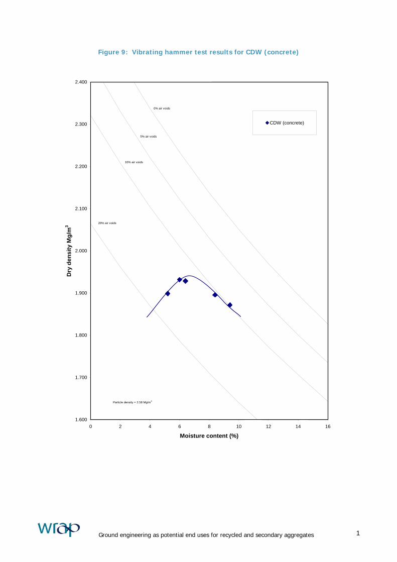
Figure 9: Vibrating hammer test results for CDW (concrete)
1.600
1.700
1.800
1.900
2.000
2.100
2.200
2.300
2.400
0 2 4 6 8 10 12 14 16
Moisture content (%)
Dry
den
sity
Mg/
m3
CDW (concrete)
0% air voids
5% air voids
10% air voids
20% air voids
Particle density = 2.58 Mg/m3
Ground engineering as potential end uses for recycled and secondary aggregates 1
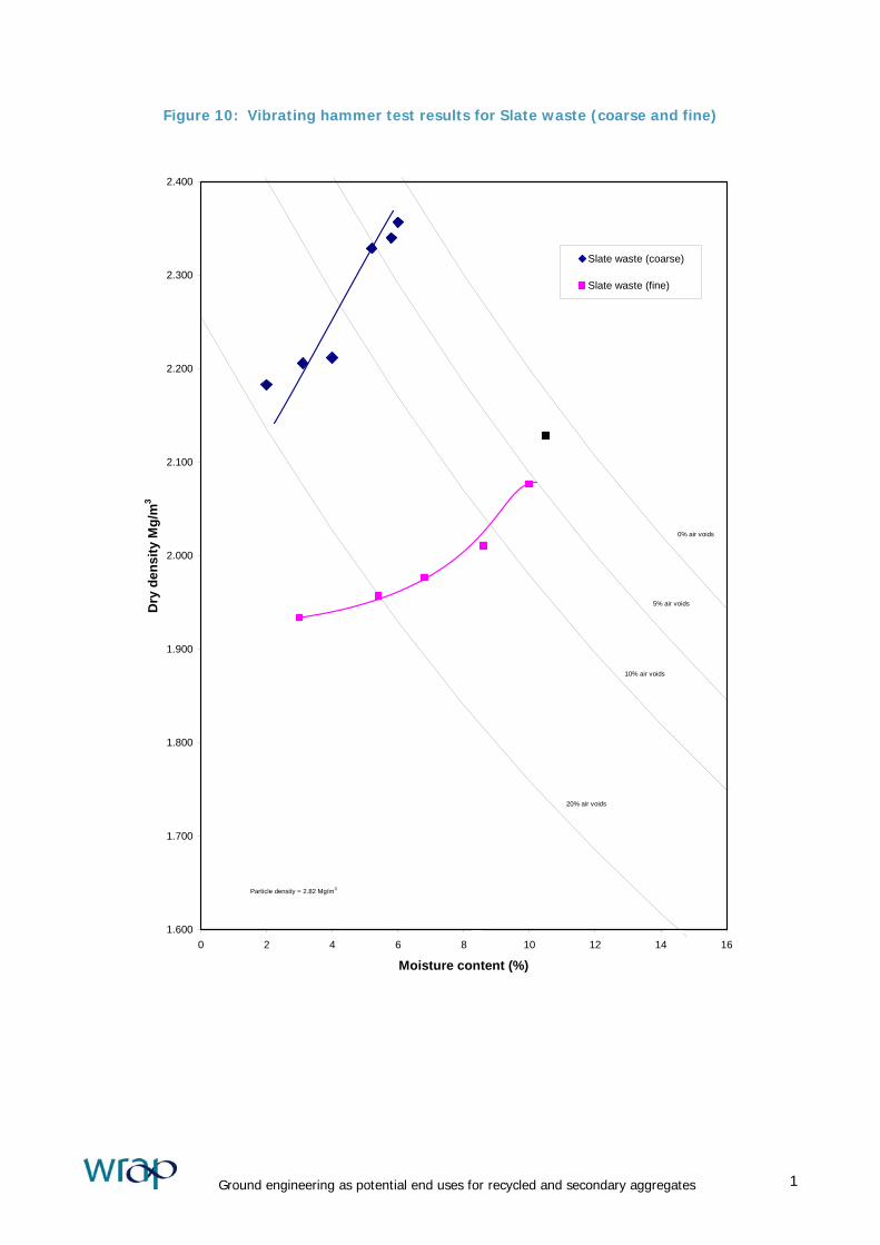
Figure 10: Vibrating hammer test results for Slate waste (coarse and fine)
1.600
1.700
1.800
1.900
2.000
2.100
2.200
2.300
2.400
0 2 4 6 8 10 12 14 16
Moisture content (%)
Dry
den
sity
Mg/
m3
Slate waste (coarse)
Slate waste (fine)
0% air voids
5% air voids
10% air voids
20% air voids
Particle density = 2.82 Mg/m3
Ground engineering as potential end uses for recycled and secondary aggregates 1
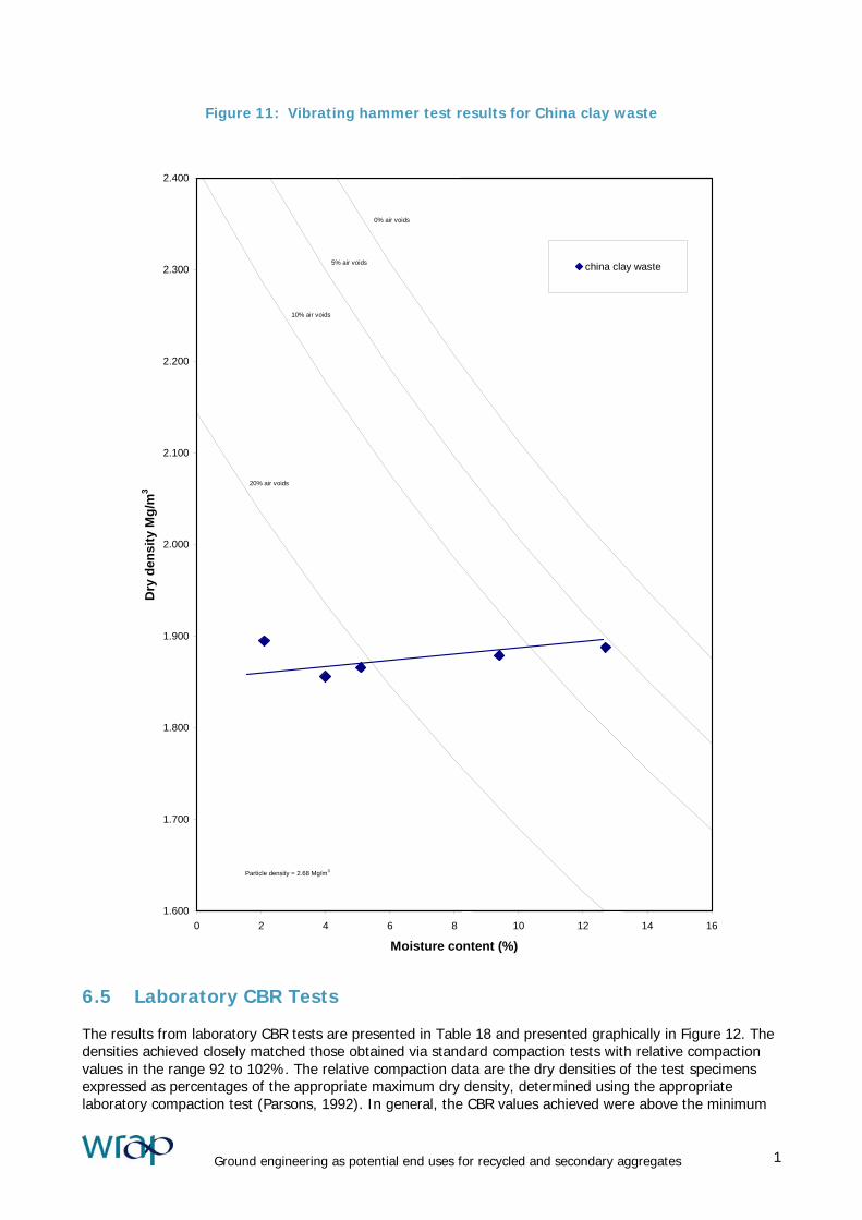
Figure 11: Vibrating hammer test results for China clay waste
1.600
1.700
1.800
1.900
2.000
2.100
2.200
2.300
2.400
0 2 4 6 8 10 12 14 16
Moisture content (%)
Dry
den
sity
Mg/
m3
china clay waste
0% air voids
5% air voids
10% air voids
20% air voids
Particle density = 2.68 Mg/m3
6.5 Laboratory CBR Tests The results from laboratory CBR tests are presented in Table 18 and presented graphically in Figure 12. The densities achieved closely matched those obtained via standard compaction tests with relative compaction values in the range 92 to 102%. The relative compaction data are the dry densities of the test specimens expressed as percentages of the appropriate maximum dry density, determined using the appropriate laboratory compaction test (Parsons, 1992). In general, the CBR values achieved were above the minimum
Ground engineering as potential end uses for recycled and secondary aggregates 1

requirement advised in HA44 (MCHW1). This advises that materials chosen for capping applications will in most cases have a CBR of 15% or greater. The fine slate waste was the only material not to achieve this threshold in all cases, with one sample having a CBR of 13.4%. On balance this material, in terms of bearing capacity, would be acceptable. However, analysis of compliance with grading requirements (Table 10) shows that this material fails to comply with either of the capping classes (Class 6F1 or Class 6F2) in the 600 Series, where specific advice is provided on CBR values, and would therefore not be suitable for this application.
Table 18: CBR data for RSA materials
Dry
Density
Air void
Content
Moisture content
(%) CBR
Material Test level
(Mg/m3) (%) Top Base Top (%) base (%)
A 1.707 21.6 6.0 6.2 64.6 69.2
B 1.651 15.3 11.0 11.9 57.9 81.4
C 1.720 10.6 12.4 11.9 31.6 78.3 CDW (brick)
D 1.672 10.1 13.6 14.3 56.0 101.0
A 1.880 12.3 7.3 8.5 119.2 111.9
B 1.868 13.6 7.0 7.9 123.6 104.7
C 1.901 9.2 8.1 9.9 149.9 141.9
D 1.782 14.0 9.1 9.9 105.2 111.5 CDW (concrete)
4
(<37.5mm) 1.896 10.6 7.0 9.9 157.1 92.3
A 2.186 13.1 4.1 4.5 53.5 62.9
B 2.250 8.1 5.0 5.7 42.4 52.4
C 2.284 5.1 6.4 5.7 38.3 45.9
Slate waste
(coarse)
<37.5 2.206 14.9 3.0 3.2 53.5 68.1
A 1.934 25.7 2.9 3.0 16.7 19.1
B 1.957 20.1 5.3 5.4 27.5 34.3
C 1.977 16.4 6.8 6.8 19.4 31.2
D 2.011 11.4 8.5 8.7 20.4 22.4
E 2.077 5.7 10.0 9.9 13.4 26.3
Slate waste
(fine)
F 2.129 2.2 10.9 9.6 17.1 22.9
A 1.895 25.3 2.3 2.2 34.8 22.8
B 1.856 23.3 4.4 4.3 51.3 46.7
C 1.866 20.8 5.4 5.1 37.7 35.7
D 1.879 12.2 9.0 9.3 37.7 64.9
China clay
waste
E 1.888 5.6 11.2 10.9 41.4 30.6
Ground engineering as potential end uses for recycled and secondary aggregates 1

Figure 12: Moisture content versus CBR for RSA materials
10
100
1000
0 2 4 6 8 10 12 14
Moisture content (%)
CB
R (%
)
16
CDW (brick)CDW (concrete)Slate waste (coarse)Slate waste (fine)China clay waste
Ground engineering as potential end uses for recycled and secondary aggregates 1

6.6 Crushing strength (10% fines test)
Table 19: 10% fines results for RSA materials
Material Test No 10% fines
(kN)
Mean
(kN)
CDW (brick)
1
2
3
4
55
55
55
55
55
Sample comprising
pure brick and mortar
1
2
3
4
70
70
45
50
60
CDW (concrete)
1
2
3
4
90
90
95
100
95
Slate waste (coarse)
1
2
3
4
110
110
110
110
110
Slate waste (fine)
1
2
3
4
120
120
120
130
120
Note: tests carried out in soaked condition on 14mm to 10mm samples, except slate waste (fine)
where test performed on 10mm to 6.3mm samples
Table 20: 10% fines requirements from Table 6/1 (600 Series) and RSA material compliance
Material complies
Acceptable limits within Material
Class
(600 Series)
Lower Upper
CDW (brick) CDW (concrete) Coarse slate Fine slate
1C 50kN -
6B 50kN -
6C 50kN -
6F1 30kN -
6F2 App 6/1 -
6G 50kN -
6H 50kN -
6K 100kN -
6M 100kN -
6N 100kN -
6P 30kN -
Ground engineering as potential end uses for recycled and secondary aggregates 1
6.7 Shear strength tests In total, twenty shear box tests were carried out. Results of these tests are presented in
Ground engineering as potential end uses for recycled and secondary aggregates 1

Table 21 to Table 25, for CDW (Brick), CDW (Concrete), slate waste (coarse), slate waste (fine) and China Clay Sand respectively. The shear stress versus displacement curves for the samples, tested under three different values of normal stress and at differing states of compaction (test sets HD and LD) are presented in, Figures 13 to 17. All shear tests were terminated at the limit of box travel or constant shear stress. In some cases, a steady state was not achieved. The equivalent failure envelopes were constructed from the best fit lines for the peak shear stress (τp) versus normal stress (σn) data for each material and state of compaction. The drained peak angles of internal friction (φ΄p) were calculated from the slopes of these best fit lines. We can compare the shear strength values typically obtained for granular materials currently used in structural fill applications, against those obtained for the RSA in this investigation. Craig (1987) indicates that typical values of φ΄ for a dense sand and gravel range between 35° and 50°. Similarly, Lambe and Whitman (1979) state that values of φ΄ for dense sand and gravel at peak strength would be in the region of 40° to 48°. All the RSA materials provided shear strengths comparable with those of natural materials.
Ground engineering as potential end uses for recycled and secondary aggregates 1
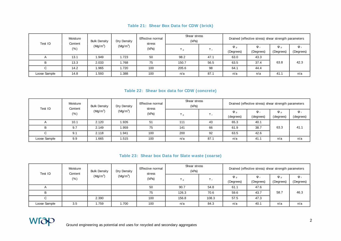
Table 21: Shear Box Data for CDW (brick)
Shear stress
(kPa) Drained (effective stress) shear strength parameters
Test ID
Moisture
Content
(%)
Bulk Density
(Mg/m3)
Dry Density
(Mg/m3)
Effective normal
stress
(kPa) τ p τ rφ p
(Degrees)
φ r(Degrees)
φ p(Degrees)
φ r(Degrees)
A 13.1 1.949 1.723 50 98.2 47.1 63.0 43.3
B 13.3 2.033 1.768 75 150.7 56.5 63.5 37.4
C
14.2 1.965 1.720 100 205.6 98 64.1 44.4
63.8 42.3
Loose Sample 14.8 1.593 1.388 100 n/a 87.1 n/a n/a 41.1 n/a
Table 22: Shear box data for CDW (concrete)
Shear stress
(kPa) Drained (effective stress) shear strength parameters
Test ID
Moisture
Content
(%)
Bulk Density
(Mg/m3)
Dry Density
(Mg/m3)
Effective normal
stress
(kPa) τ p τ rφ p
(degrees)
φ r(degrees)
φ p(degrees)
φ r(degrees)
A 10.1 2.120 1.926 51 111 43 65.3 40.1
B 9.7 2.149 1.959 75 141 66 61.9 38.7
C
9.1 2.118 1.941 100 200 92 63.5 42.6
63.3 41.1
Loose Sample 9.9 1.665 1.515 100 n/a 87.1 n/a 41.1 n/a n/a
Table 23: Shear box Data for Slate waste (coarse)
Shear stress
(kPa) Drained (effective stress) shear strength parameters
Test ID
Moisture
Content
(%)
Bulk Density
(Mg/m3)
Dry Density
(Mg/m3)
Effective normal
stress
(kPa) τ p τ rφ p
(Degrees)
φ r(Degrees)
φ p(Degrees)
φ r(Degrees)
A 50 90.7 54.8 61.1 47.6
B 75 126.3 70.6 59.6 43.7
C
2.390 100 156.8 108.3 57.5 47.3
58.7 46.3
Loose Sample 3.5 1.759 1.700 100 n/a 84.3 n/a 40.1 n/a n/a
Ground engineering as potential end uses for recycled and secondary aggregates 2

Ground engineering as potential end uses for recycled and secondary aggregates 3
Table 24: Shear box data for Slate waste (fine)
Shear stress
(kPa) Drained (effective stress) shear strength parameters
Test ID
Moisture
Content
(%)
Bulk Density
(Mg/m3)
Dry Density
(Mg/m3)
Effective normal
stress
(kPa) τ p τ rφ p
(Degrees)
φ r(Degrees)
φ p(Degrees)
φ r(Degrees)
A 8.9 2.278 2.091 50 60.0 39.1 50.2 38.0
B 9.3 2.222 2.033 75 76.6 56.4 45.6 36.9
C
10.1 2.227 2.023 100 95.4 76.3 43.7 37.3
45.3 37.3
Loose Sample 8.4 1.755 1.619 100 n/a 69.3 n/a 34.7 n/a n/a
Table 25: Shear Box data for china clay waste Shear stress
(kPa) Drained (effective stress) shear strength parameters
Test ID
Moisture
Content
(%)
Bulk Density
(Mg/m3)
Dry Density
(Mg/m3)
Effective normal
stress
(kPa) τ p τ rφ p
(Degrees)
φ r(Degrees)
φ p(Degrees)
φ r(Degrees)
A 9.7 2.124 1.936 50 90.2 36.0 60.5 35.2
B 10.0 2.092 1.902 75 124.9 57.0 59.0 37.2
C
10.3 2.075 1.881 100 147.0 71.0 55.8 35.4
57.6 35.9
Loose Sample 11.3 1.771 1.591 100 n/a 71.0 n/a 35.4 n/a n/a
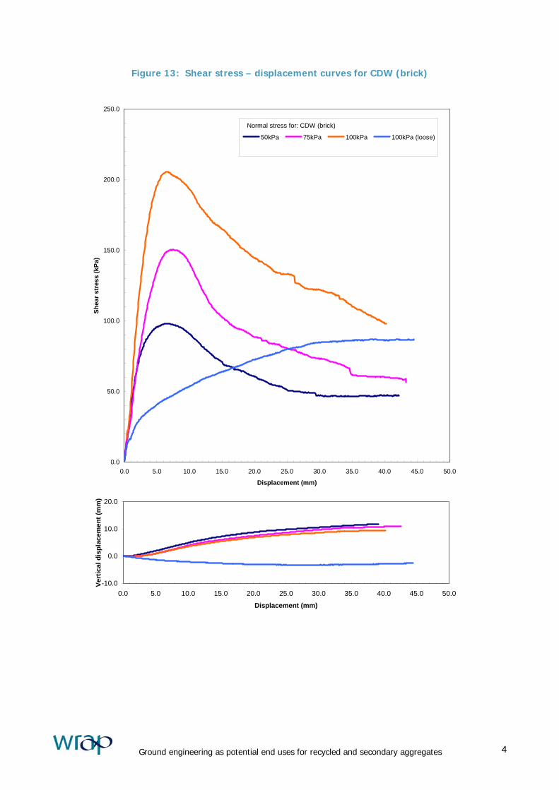
Figure 13: Shear stress – displacement curves for CDW (brick)
0.0
50.0
100.0
150.0
200.0
250.0
0.0 5.0 10.0 15.0 20.0 25.0 30.0 35.0 40.0 45.0 50.0
Displacement (mm)
Shea
r str
ess
(kPa
)
50kPa 75kPa 100kPa 100kPa (loose)
Normal stress for: CDW (brick)
-10.0
0.0
10.0
20.0
0.0 5.0 10.0 15.0 20.0 25.0 30.0 35.0 40.0 45.0 50.0
Displacement (mm)
Vert
ical
dis
plac
emen
t (m
m)
Ground engineering as potential end uses for recycled and secondary aggregates 4
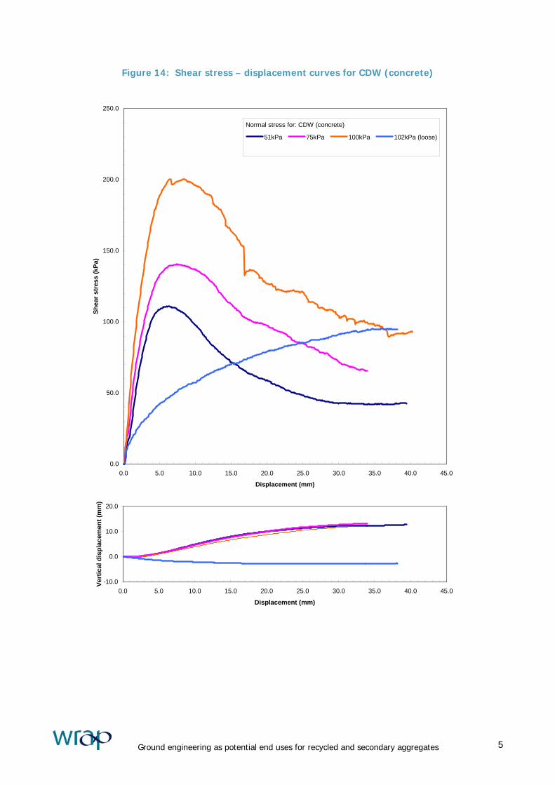
Figure 14: Shear stress – displacement curves for CDW (concrete)
0.0
50.0
100.0
150.0
200.0
250.0
0.0 5.0 10.0 15.0 20.0 25.0 30.0 35.0 40.0 45.0
Displacement (mm)
Shea
r str
ess
(kPa
)
51kPa 75kPa 100kPa 102kPa (loose)
Normal stress for: CDW (concrete)
-10.0
0.0
10.0
20.0
0.0 5.0 10.0 15.0 20.0 25.0 30.0 35.0 40.0 45.0
Displacement (mm)
Vert
ical
dis
plac
emen
t (m
m)
Ground engineering as potential end uses for recycled and secondary aggregates 5

Figure 15: Shear stress – displacement curves for slate waste (coarse)
0.0
20.0
40.0
60.0
80.0
100.0
120.0
140.0
160.0
180.0
0.0 5.0 10.0 15.0 20.0 25.0 30.0 35.0 40.0 45.0 50.0
Displacement (mm)
Shea
r str
ess
(kPa
)
50 kPa 74kPa 100kPa 100kPa (loose)
Normal stress for: Slate waste (coarse)
-10.0
0.0
10.0
20.0
0.0 5.0 10.0 15.0 20.0 25.0 30.0 35.0 40.0 45.0 50.0
Displacement (mm)
Vert
ical
dis
plac
emen
t (m
m)
Ground engineering as potential end uses for recycled and secondary aggregates 6
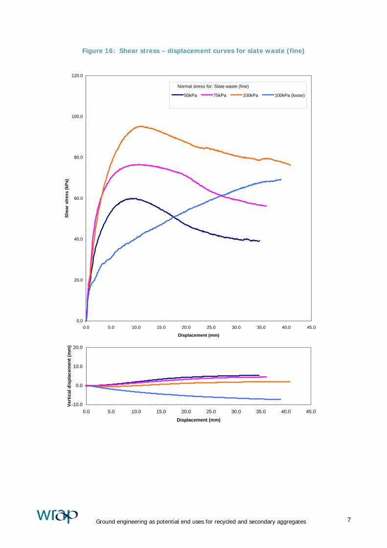
Figure 16: Shear stress – displacement curves for slate waste (fine)
0.0
20.0
40.0
60.0
80.0
100.0
120.0
0.0 5.0 10.0 15.0 20.0 25.0 30.0 35.0 40.0 45.0
Displacement (mm)
Shea
r str
ess
(kPa
)
50kPa 75kPa 100kPa 100kPa (loose)
Normal stress for: Slate waste (fine)
-10.0
0.0
10.0
20.0
0.0 5.0 10.0 15.0 20.0 25.0 30.0 35.0 40.0 45.0
Displacement (mm)
Vert
ical
dis
plac
emen
t (m
m)
Ground engineering as potential end uses for recycled and secondary aggregates 7

Figure 17: Shear stress – displacement curves for China clay waste
0.0
20.0
40.0
60.0
80.0
100.0
120.0
140.0
160.0
0.0 5.0 10.0 15.0 20.0 25.0 30.0 35.0 40.0
Displacement (mm)
Shea
r str
ess
(kPa
)
51kPa 75kPa 100kPa 101kPa (loose)
Normal stress for: China clay waste
-10.0
0.0
10.0
20.0
0.0 5.0 10.0 15.0 20.0 25.0 30.0 35.0 40.0
Displacement (mm)
Vert
ical
dis
plac
emen
t (m
m)
Ground engineering as potential end uses for recycled and secondary aggregates 8
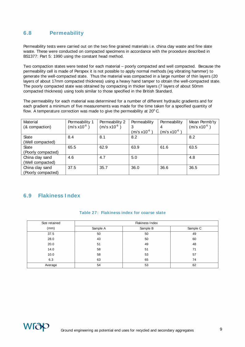
6.8 Permeability
Permeability tests were carried out on the two fine grained materials i.e. china clay waste and fine slate waste. These were conducted on compacted specimens in accordance with the procedure described in BS1377: Part 5: 1990 using the constant head method. Two compaction states were tested for each material – poorly compacted and well compacted. Because the permeability cell is made of Perspex it is not possible to apply normal methods (eg vibrating hammer) to generate the well-compacted state. Thus the material was compacted in a large number of thin layers (20 layers of about 17mm compacted thickness) using a heavy hand tamper to obtain the well-compacted state. The poorly compacted state was obtained by compacting in thicker layers (7 layers of about 50mm compacted thickness) using tools similar to those specified in the British Standard. The permeability for each material was determined for a number of different hydraulic gradients and for each gradient a minimum of five measurements was made for the time taken for a specified quantity of flow. A temperature correction was made to give the permeability at 20o
C. Material (& compaction)
Permeability 1 (m/s x10-6 )
Permeability 2 (m/s x10-6 )
Permeability 3 (m/s x10-6 )
Permeability 4 (m/s x10-6 )
Mean Permb’ty (m/s x10-6 )
Slate (Well compacted)
8.4 8.1 8.2 8.2
Slate (Poorly compacted)
65.5 62.9 63.9 61.6 63.5
China clay sand (Well compacted)
4.6 4.7 5.0 4.8
China clay sand (Poorly compacted)
37.5 35.7 36.0 36.6 36.5
6.9 Flakiness Index
Table 27: Flakiness index for coarse slate
Flakiness Index Size retained
(mm) Sample A Sample B Sample C
37.5 50 50 49
28.0 43 50 60
20.0 51 49 48
14.0 58 51 71
10.0 58 53 57
6.3 63 65 74
Average 54 53 62
Ground engineering as potential end uses for recycled and secondary aggregates 9
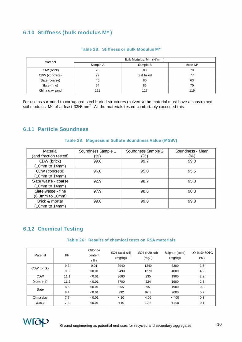
6.10 Stiffness (bulk modulus M*)
Table 28: Stiffness or Bulk Modulus M*
Bulk Modulus, M* (N/mm2) Material
Sample A Sample B Mean M*
CDW (brick) 70 88 79
CDW (concrete) 77 test failed 77
Slate (coarse) 45 80 63
Slate (fine) 54 85 70
China clay sand 121 117 119
For use as surround to corrugated steel buried structures (culverts) the material must have a constrained soil modulus, M* of at least 33N/mm2.. All the materials tested comfortably exceeded this. 6.11 Particle Soundness
Table 28: Magnesium Sulfate Soundness Value (MSSV)
Material (and fraction tested)
Soundness Sample 1 (%)
Soundness Sample 2 (%)
Soundness - Mean (%)
CDW (brick) (10mm to 14mm)
99.8 99.7 99.8
CDW (concrete) (10mm to 14mm)
96.0 95.0 95.5
Slate waste - coarse (10mm to 14mm)
92.9 98.7 95.8
Slate waste - fine (6.3mm to 10mm)
97.9 98.6 98.3
Brick & mortar (10mm to 14mm)
99.8 99.8 99.8
6.12 Chemical Testing
Table 26: Results of chemical tests on RSA materials
Material PH
Chloride
content
(%)
SO4-(acid sol)
(mg/kg)
SO4-(h20 sol)
(mg/l)
Sulphur (total)
(mg/kg)
LOI%@450ФC
(%)
9.3 0.01 8940 1240 3300 3.5 CDW (brick)
9.3 <0.01 9490 1270 4000 4.2
11.1 <0.01 3660 235 1900 2.2 CDW
(concrete) 11.2 <0.01 3700 224 1900 2.3
8.5 <0.01 255 95 1900 0.8 Slate
8.4 <0.01 292 97.3 2600 0.7
7.7 <0.01 <10 4.09 <400 0.3 China clay
waste 7.5 <0.01 <10 12.3 <400 0.1
Ground engineering as potential end uses for recycled and secondary aggregates 10

7 Discussion
The main purpose of this report is to provide various engineering properties of RSA for the particular materials sampled. This information is provided in the body of the report and should be of value to potential users of RSA in road construction. The results reported are simply the results of a limited number of tests and there is no guarantee that future tests on the material, even from the same source would be the same. At this stage the data should be considered as indicating the sort of values one might expect and for specific schemes the Engineer will normally require evidence of compliance with the specification within his contract documents and some assurance of continuing compliance. The contract documents for a specific scheme may well contain additional specification Clauses to take advantage of known, suitable local materials as well as the normal specification requirements given mainly in Tables 6/1 and 6/2 of the Specification for Highway Works (MCHW1). In this section of the report, some commentary is provided on many of the soil or aggregate materials found in the SHW. A wide range of soils and aggregates is employed in road construction and a very large range of tests are required for some applications. A limited range of tests were carried out during this work such that an indication of suitability, rather than a definitive answer must be offered in many places. As one would expect, a wide specification is given for less critical applications such as general fill or fill to landscape areas. For more critical uses the material must comply with much tighter requirements in the tender documents. To encourage the use of recycled and secondary materials the Highways Agency published technical information on the conservation and use of reclaimed materials in DMRB 7.1.2 as HD 35/95. This gives general advice, much of which was confirmed by the testing carried out as part of this project. Although HD 35 is current the increasing trend to maximise re-use of material plus a number of recent changes to the SHW may require HD35 to be revised. The main chapters (termed ‘Series’) in the SHW where RSA might be employed are:- • 500 Series Pipes and drainage • 600 Series Earthworks • 800 Series Pavements – unbound materials and • 900 Series Pavements – bitumen bound materials The use of RSA in concrete is discussed in the ‘sister report’ to this one ‘Low strength concrete ground engineering applications for recycled and secondary aggregates’ by C R Sowerby. Where clauses relating to aggregates exist in other series the materials are generally included in Table 6/1 of the 600 Series. In some cases the RSA material tested during this work is obviously outside the specification (eg where cohesive material or topsoil is described). Where granular materials are required the grading (size and distribution of particles) will often determine whether the RSA material is suitable. As the particular application becomes more specific additional requirements have to be met. When RSA material fails to meet one of the criteria it becomes unsuitable for that application. Some of the waste materials will be unsuitable for more than one reason but this limited commentary cannot cover all of the relevant properties. Although strictly the DfT Specification relates to the Highways Agency’s trunk roads, in practice it is used for the great majority of roads built in the UK.
Ground engineering as potential end uses for recycled and secondary aggregates 11
7.1 Pipes and drainage (500 Series) Flexible pipes (eg uPVC) are generally bedded on and surrounded with granular material while rigid pipes (eg clay) may be surrounded by the as-dug material from the trench thus imported fill is sometimes not required with rigid pipes. Bedding and surround to pipes should be compacted, so a reasonably well-graded material is normally used where compaction plant can be employed and ‘pea-gravel’ (a single-size, rounded, self-compacting material) is used where plant cannot be employed (eg in narrow trenches or voids around manhole chambers). There are a range of permitted gradings for pipe bedding and surround in the 500 Series – most being taken from BS882 Aggregates from natural sources for concrete. The coarser waste materials CDW (brick), CDW (concrete) and coarse slate waste approximate to the ‘all-in aggregate’ requirements. Generally, the wide range of pipe bedding and surround specified in the SHW, water industry and other standards means a more detailed examination of the materials is needed before a definitive decision can be made on material suitability. Unnpublished work at TRL found that many utility companies used a Type 1 sub-base for much pipe laying or pipe repairing work to minimise the number of materials needed on their sites. Filter drains (previously termed ‘French drains’) contain a perforated pipe generally surrounded with cobble-size granular material (Type B filter material). None of the RSA tested fell within the tight, single size grading required. Even if the demolition waste was processed to meet the Type B grading where the material can readily be seen in the road verge any visible contaminants (soil, plastics, wood, metal etc) would make the material unattractive even if it performed satisfactorily. 7.2 Earthworks (600 Series) The requirements for materials used in earthworks are given mainly in Tables 6/1 and 6/2 of the SHW and are placed in a variety of classes (developed and modified as necessary for individual highway schemes). General Fill Classes 1, 2 and 3 within this table are ‘General Fill’. All the RSA tested falls within Class 1A – well graded granular fill or Class 1B – uniformly graded granular fill. None of it fell in Class 1C as it is not sufficiently coarse. However, general fill either Class 1 – granular, Class 2 – cohesive or Class 3 - chalk is usually widely available on road construction sites and imported material is rarely required. Where import of general fill is necessary any of the five materials tested could be used. However, poorer quality material than these might be available and the proximity to the site (and thus cost of transport) is likely to be a more important factor in determining the material employed. Fill to Landscape Class 4 material is fill to landscape areas. The requirements for this application are very undemanding and imported material is rarely employed. The landscape outline is often determined or modified to suit the amount of fill or excess material on site. Thus although all the RSA tested it complies with the specification it is very unlikely that CDW (brick) would be employed in this application. Topsoil Class 5 material is topsoil or turf so all the RSA materials are obviously unsuitable. Selected Granular Fill Class 6 material with its sub-divisions is ‘selected granular fill’ for specific applications. Class 6A is selected well graded granular material (typically used in below water applications). The three coarse materials CDW (brick0, CDW (concrete) and Slate (coarse) would comply with the two finer materials being borderline.
Ground engineering as potential end uses for recycled and secondary aggregates 12

Class 6B, is selected coarse granular material, 6C and 6D are selected uniformly graded granular material, all for starter layers. None of the five materials are likely to comply with the grading requirements. Class 6E material is normally in-situ material which is stabilised rather than imported. HD 35 permits the use of demolition waste but it is likely to be outside the limits for some of its chemical properties Class 6F material is for a capping layer and all the material fell within Class 6F1, fine material for capping or 6F2 coarse material for capping. The coarse slate was on the borderline between the fine and coarse categories. Class 6G material is fill for gabions, Any of the three coarser materials might comply but the grading specification would depend on the particular gabion employed and its mesh size. For best results gabions are filled with approximately regular (brick-shaped) stone on their exposed faces for maximum strength and appearance. For locations where they are readily seen gabions filled with either of the demolition materials might well be considered unattractive. Class 6H material is selected granular material for use as a drainage layer to reinforced earth and anchored earth structures. Most of the RSA materials fell outside the grading requirements. The fine slate was within grading but its low permeability might make it unattractive for this application. Class 6I material is selected well graded granular fill to reinforced earth and anchored earth structures. Four of the materials are unsatisfactory or borderline on grading and/or uniformity. CDW (brick) complies with the grading but is outside the pH and the organic content values. To use a demolition waste in reinforced earth or anchored earth structures more chemical testing, including resistivity, redox and microbial assessments would have to be carried out. Where initial testing showed compliance with the specification the Engineer for the scheme would require some assurance that all deliveries of the material met and maintained the values in the SHW. Class 6J is uniformly graded granular fill to reinforced earth and anchored earth structures. Four of the materials are unsatisfactory or borderline on grading and/or uniformity. The China clay sand could potentially be used but additional chemical testing would be needed. including resistivity, redox and microbial assessments.. Where initial testing showed compliance with the specification the Engineer for the scheme would require some assurance that all deliveries of the material met and maintained the values in the SHW. Classes 6K, 6L and 6M are used in the construction of corrugated steel buried structures (culverts). Class 6K is selected granular fill as lower bedding for steel culverts. Four of the RSA materials tested fell outside the grading or uniformity requirements. Fine slate could potentially be used and this also meets the 10% fines strength requirement. However additional chemical testing would be required to ensure full compliance. None of the materials comply with the grading and uniformity requirements of Class 6L, selected uniformly graded granular material used as upper bedding for steel culverts. All the materials meet the grading and uniformity requirements for Class 6M, selected granular material used as surround to steel culverts. However only the coarse slate and fine slate meet the 10% fines limit of 100kNhowever, both would need further testing to check for aggresivity , including resistivity testing before the material could be used. Class 6N is well graded granular material for use as fill to structures. CDW (brick) and coarse slate both meet the grading and uniformity requirements in Table 6/1. CDW (brick) does not meet the 10% fines strength requirement but coarse slate appears to meet all the requirements for Class 6N. Class 6P is granular material used as fill to structures. All the materials meet the grading and uniformity requirements as well as the 10% fines value. The shear strength and angle of internal friction would be specified for the particular structure but all the measured values are reasonably high. The permeability of the two fine materials would need to be checked against any specified requirements. Class 6Q is Class 1 material used as overlying fill for corrugated steel structures with additional chemical requirements. The chemical properties of the two demolition materials would probably exclude their use in this application.
Ground engineering as potential end uses for recycled and secondary aggregates 13
Class 6R would normally be an in-situ material for stabilisation to form capping and imported materials are unlikely to be economic. Cohesive fill All the Class 7 materials (Class7A to Class 7I) are cohesive and thus do not relate to the materials tested during this work. Lower trench fill Class 8 material is general fill material used as lower trench fill (material above the pipe surround and below the sub-base in a road). It is fairly low quality material and normally on-site materials would be employed. Imported materials could be employed but are unlikely to be economic. In addition the three coarse materials had particles greater than 40mm nominal diameter and should be excluded on that basis. Stabilised materials Class 9 materials (Class 9A to Class 9F) are materials which have already been stabilised with cement and/or lime and thus are not relevant to the RSA materials considered in this report. 7.3 Pavements – unbound materials (800 Series) The most-used material within the 800 Series of the SHW is Granular sub-base Type 1. Of the RSA materials under consideration, the coarse slate and CDW (brick) approximate to the appropriate grading envelope. Further testing would be required to confirm that the grading can be achieved consistently. All the materials meet the 10% fines requirement although CDW (brick) only just exceeds it. Similarly all the materials exceed the required magnesium sulphate soundness value. 7.4 Pavements - bituminous bound materials (900 Series) The basic requirement for Aggregates used in bituminous materials is that they are hard, clean and durable. Aggregates for bituminous material need to lie within tight grading requirements and all the RSA materials would need considerable crushing, and/or grading and blending to comply. None of the RSA materials reach the hardness requirement (10% fines value of 140kN) although all meet the durability requirement with a MMSV in excess of 75%. The cleanliness aspect of the demolition materials would need to be improved by removing impurities (soil, wood, plastics etc) and some of the fine material. Significantly more testing would be needed of any material before it could be used as a bituminous bound material.
Ground engineering as potential end uses for recycled and secondary aggregates 14
8 Conclusions
A range of tests was carried out on five materials. These results could form part of a database (perhaps on the AggRegain website) on material properties to aid potential suppliers and users considering these RSA materials in various applications. Additional data, existing or generated specifically for the database will be needed to give confidence in the consistency of the materials. When established, the database will help contractors and engineers to check compliance with the Department for Transport Specification (and other major specifications). With the move towards European Standards there may tend to be a reduction in ‘industry-specific’ specifications and increase in ‘universal’ specifications which would simplify and encourage greater use of RSA.
Ground engineering as potential end uses for recycled and secondary aggregates 15

9 References
BRADY, KC, I AWCOCK and NR WIGHTMAN (1983). A comparison of shear strength measurements using two sizes of shear box. TRRL Laboratory Report 1105. Crowthorne: Transport Research Laboratory. BRITISH STANDARDS INSTITUTION (1990). Methods of Test for Soils for Civil Engineering Purposes. British Standard BS 1377 : 1990. British Standards Institution, London. BROOKES, AH (1995). Permeability testing of recycled bituminous planings. TRL Project Report PR/CE/146/95. Crowthorne: Transport Research Laboratory. (Unpublished report available on direct personal application only) CRAIG, RF (1987). Soil mechanics, fourth edition. London: Van Nostrand Reinhold (International) Co. Ltd. DESIGN MANUAL FOR ROADS AND BRIDGES. Her Majesty’s Stationery Office, London. HA 44 Earthworks: Design and Preparation of Contract Documents (DMRB 4.1.1) HD 35 Technical Information (Conservation and use of reclaimed materials) (DMRB 7.1.2) HEAD, KH (1994). Manual of soil laboratory testing, Vol 2, second edition. New York: John Wiley & Sons. LAMBE, TW, and RV WHITMAN (1979). Shear strength of cohesionless soil. Soil mechanics, SI version. New York: John Wiley & Sons. Chapter 11. MANUAL OF CONTRACT DOCUMENTS FOR HIGHWAY WORKS. Her Majesty’s Stationery Office, London. Volume 1: Specification for Highway Works (December 1991, reprinted August 1993 with amendments). (MCHW 1). MURRAY, RT, and DM FARRAR (1988). Temperature distributions in reinforced soil retaining walls. Geotextiles and Geomembranes, 7, pp 33-50. SHERWOOD, PT (1995). Alternative materials in road construction. London: Thomas Telford. TOOMBS, AF, RA SNOWDON and DP STEELE (1994). The use of recycled bituminous materials for capping layers. TRL Project Report PR/CE/25/94. Crowthorne: Transport Research Laboratory. (Unpublished report available on direct personal application only)
Ground engineering as potential end uses for recycled and secondary aggregates 16


![Index Terms IJSER · ‘shape of aggregates’ is measured in terms of Flakiness Index (FI), Elongation Index (EI) and Angularity Number (AN) [1]. Flaky](https://img.dokumen.tips/doc/110x75/5b79730e7f8b9a31308db7a4/index-terms-ijser-shape-of-aggregates-is-measured-in-terms-of-flakiness.jpg)