Embed Size (px)
Citation preview
User’sManual
MC1/AC1Single Channel Calibration UnitFor use with ZR402G
IM 11M06D03-01E-A
Copyright 20074th Edition Feb 2013
IM 11M06D03-01E-A
User’sManual
IM 11M06D03-01E-A
3rd Edition
MC1/AC1Single Channel Calibration Unit
For use with ZR402G
4th Edition
I. Introduction............................................................................................4II. Overview……………………………………………………………….........4 2.1 Principles of Calibration…………………………………………………..............................4 2.2 Gases………………………………………………………………………….........................5 2.2.1 Span/Reference Gas…………………………………………………………........................5 2.2.2 Calibration Gas (Zero Gas)………………………………………………….........................5
III. Specifications…………………………………………………................…6 3.1 Model MC1, Manual Calibration Panel…………………………………….........................6 3.1.2OrderingSpecifications……………………………………………………...........................7 3.2 Specifications,AC1…………………………………………………………..........................8 3.2.1 ModelAC1,SinglePointAutomaticCalibrationUnit……………………….. ...................8 3.2.2 AC1OrderingSpecifications………………………………………………..........................9
IV. Installation, Manual Calibration (MC1)………………………...…........10 4.1 Location…………………………………………………………………...............................10 4.2 Mounting the MC1…………………………………………………………..........................10 4.3 Piping…………………………………………………………………………........................10 4.3.1 Piping to the ZR22G Oxygen Probe………………………………………........................10 4.3.2 Connection to the Calibration Gas Inlet……………………………………......................10 4.3.3 Connection to the Reference Gas Inlet…………………………………...........................11
V. Setup Procedures, MC1…………………………………………….........12 5.1 Initial Flow Rate Setup………………………………………………………………............12 5.2 MC1 Flow Rate Setup……………………………………………………………….............12 5.3 Checking for leaks…………………………………………………………………...............12
VI. Installation, Automatic Calibration, AC1…………………….....…......13 6.1 Location………………………………………………………………………….... ...............13 6.2 Mounting the AC1………………………………………………………………..….............13 6.3 Piping………………………………………………………………………………................13 6.3.1 Piping to the ZR22G Oxygen Probe………………………………………...….................13 6.3.2 Connection to the Calibration Gas Inlet………………………………………..................13 6.3.3 Connection to the Reference Gas Inlet…………………………………...……................13 6.4. Wiring to the AC1, Automatic Calibration Unit……………………………………...........13 6.4.1 Wiring the AC1 to the ZR22G…………………………………………...……...................13
VII. Setup Procedures, AC1……………………………………………..........15 7.1 Initial Flow Rate Setup………………………………………………………………............15 7.1.2 Setting the Reference Air Flow Rates………………………………………….................15 7.1.3 Balancing Pressure Drops in the Calibration Lines……………………………...............15 7.2 Standard Operation…………………………………………………………………............15 7.3 Checking for leaks…………………………………………………………………...............16
VIII. Calibration Setup & Operation, ZR402G…………………………........17 8.1 ZR402GTouchPanelSwitchOperations…………………………………………............17 8.2 Calibration…………………………………………………………………………................18 8.2.1 ModeSetting…………………………………………………………………......................18 8.2.2 Zero-gasConcentration………………………………………………………....................18 8.2.3 Span-gasConcentration………………………………………………………...................19 8.3 ManualCalibration…………………………………………………………………..............19 8.4 Semi-automaticCalibration………………………………………………………...............19 8.5 AutomaticCalibration……………………………………………………………................ 20
Appendix A, Spare Parts…………………………………………………….......21Appendix B, Dimensional Drawings……………………………………….......24Appendix C, Wiring Diagrams……………………………………………..........28

3
IM 11M06D03-01E-A
4
IM 11M06D03-01E-A
I. INTRODUCTION
TherearetwotypesofsinglechannelcalibrationunitsofferedbyYokogawa.Thesecalibrationunitsareusedwiththe ZR402G Single Channel Oxygen Analyzer, to perform calibration of either ZR22G or ZO21D (obsolete) Oxygen Probes.
TheAC1AutomaticCalibrationUnitutilizeselectricalsolenoidsthatarewiredtoandactuatedbytheZR402G.OnceactivatedbytheZR402G,thecalibrationgasesflowtotheZR22withouttheuseropeningvalvesoradjustingflowrates.TheMC1ManualCalibrationUnitisnotelectronicallycontrolledbytheZR402G.Duringcalibrationmode,theusermustopenvalvesandadjusttheflowratesofthecalibrationgases.BoththeMC1andtheAC1provideasinglepoint of control for the calibration system.
II. OVERVIEW
2.1 CALIBRATION PRINCIPLESThissectionsetsforththeprinciplesofmeasurementwithaZirconiaoxygenanalyzerbeforedetailingcalibration.
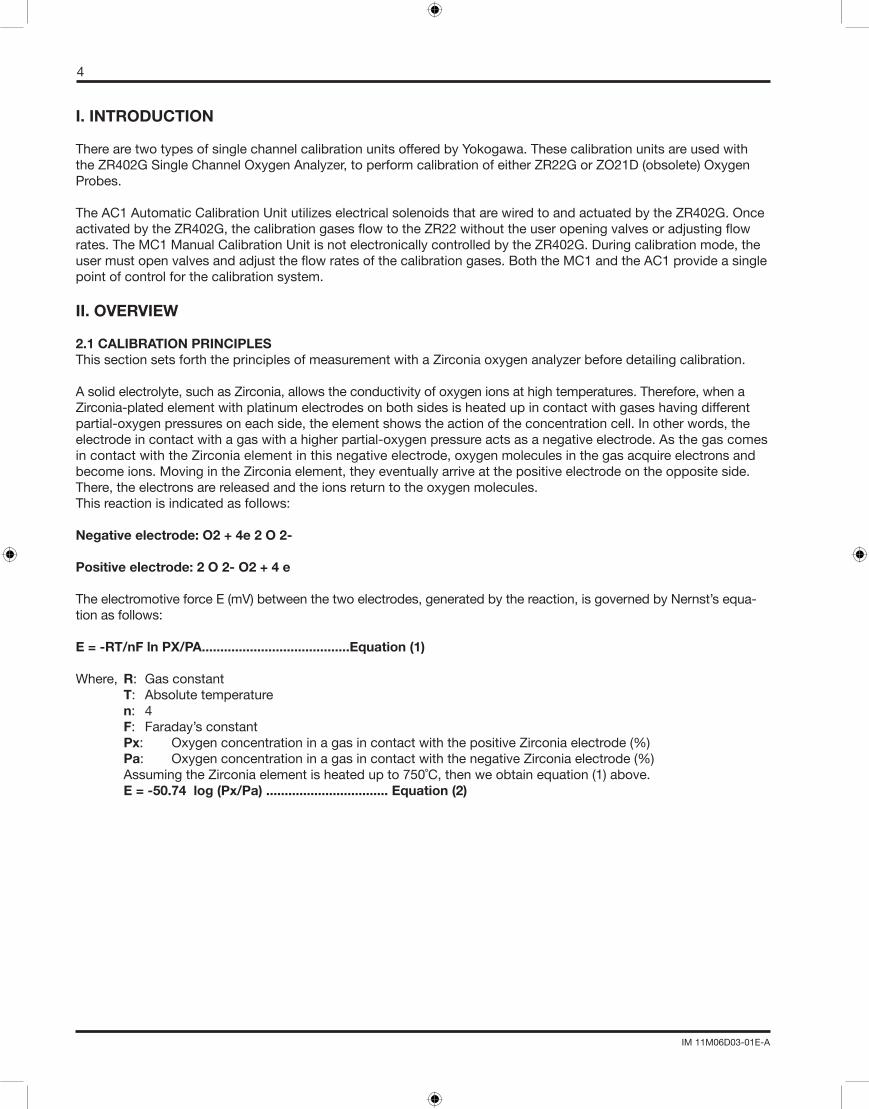
Asolidelectrolyte,suchasZirconia,allowstheconductivityofoxygenionsathightemperatures.Therefore,whenaZirconia-plated element with platinum electrodes on both sides is heated up in contact with gases having different partial-oxygen pressures on each side, the element shows the action of the concentration cell. In other words, the electrode in contact with a gas with a higher partial-oxygen pressure acts as a negative electrode. As the gas comes in contact with the Zirconia element in this negative electrode, oxygen molecules in the gas acquire electrons and become ions. Moving in the Zirconia element, they eventually arrive at the positive electrode on the opposite side. There,theelectronsarereleasedandtheionsreturntotheoxygenmolecules.Thisreactionisindicatedasfollows:
Negative electrode: O2 + 4e 2 O 2-
Positive electrode: 2 O 2- O2 + 4 e
TheelectromotiveforceE(mV)betweenthetwoelectrodes,generatedbythereaction,isgovernedbyNernst’sequa-tionasfollows:
E = -RT/nF ln PX/PA........................................Equation (1)
Where, R:Gasconstant T: Absolutetemperature n: 4 F: Faraday’sconstant Px: OxygenconcentrationinagasincontactwiththepositiveZirconiaelectrode(%) Pa: OxygenconcentrationinagasincontactwiththenegativeZirconiaelectrode(%) AssumingtheZirconiaelementisheatedupto750˚C,thenweobtainequation(1)above. E = -50.74 log (Px/Pa) ................................. Equation (2)

5
IM 11M06D03-01E-A
Withthisanalyzer,thesensor(Zirconiaelement)isheatedupto750˚C,soEquation(2)isvalid.Atthatpoint,therelationship as in Figure 2.1 is effected between the oxygen concentration of the measurement gas in contact with the positive electrode and the electromotive force of the sensor (= cell), where a comparison gas of air is used on the negative electrode side.
Figure 2.1
2.2 CALIBRATION GASES
2.2.1 CALIBRATION (ZERO) GAS
Thecalibrationgastypicallyusedis1%oxygenbalancedinnitrogen;however,anoxygenmixturebetween0.4%and8%isacceptable.Acompressedgascylinderiscontainingcertifiedgasmixturesfittedwithadualstageregulatorshouldbeused.Themaximumworkingpressureofthecalibrationsystems(MC1&AC1)is35psig.Thereferencegasshould be clean, dry instrument air.
2.2.2 REFERENCE (SPAN) GAS
Referenceairisfromthesamesourceasthespangas.ThereferenceairflowstothebacksideoftheoftheZirconiacell,andisusedatalltimes.Thecalibrationunitsareplumbedtoprovideacontinuousflowrateofthereference,aswellas,calibrationgasflowduringcalibration.Aclean,dryairsourceisrecommended,suchasinstrumentair.Installaninlinefilterbeforethecalibrationunittoremoveanymoistureordirt.Aregulatormustbeattachedtotheinstrumentairsourcetoprovidetheappropriateworkingpressureforthecalibrationunit.Themaximumpressureis35psig.
Never use pure nitrogen for calibration.
Compressed gas cylinders must have the same CGA connection as the dual stage regulator. Refer to the Appendix A (Spare Parts section) of this manual for the Dual Stage Regulator (M1132ZX) and the Zero Pressure Switch (M1133AR).
NOTE
NOTE
6
IM 11M06D03-01E-A
III. SPECIFICATIONS, MC1
3.1 MODEL MC1, MANUAL CALIBRATION PANEL
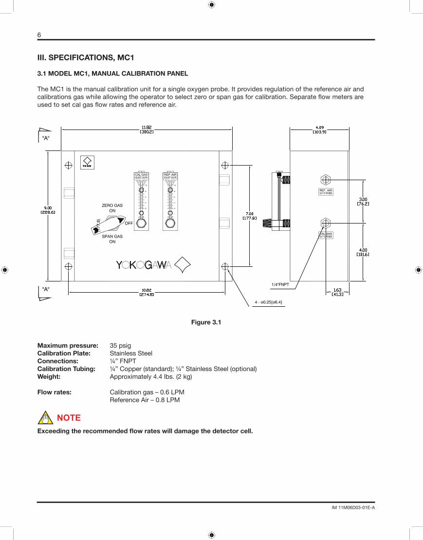
TheMC1isthemanualcalibrationunitforasingleoxygenprobe.Itprovidesregulationofthereferenceairandcalibrationsgaswhileallowingtheoperatortoselectzeroorspangasforcalibration.Separateflowmetersareusedtosetcalgasflowratesandreferenceair.
Figure 3.1
Maximum pressure: 35 psigCalibration Plate: Stainless SteelConnections: ¼”FNPTCalibration Tubing: ¼”Copper(standard);¼”StainlessSteel(optional)Weight: Approximately 4.4 lbs. (2 kg)
Flow rates: Calibration gas – 0.6 LPM ReferenceAir–0.8LPM
Exceedingtherecommendedflowrateswilldamagethedetectorcell.
NOTE

7
IM 11M06D03-01E-A
3.1.2 ORDERING SPECIFICATIONS:
Table 3.1
SINGLE CHANNEL O2 MANUAL CALIBRATION
MODEL NUMBERMC1
TUBING/FITTINGS
1/4”CopperTubingandBrassFittings-C
1/4”StainlessSteelTubingandFittings-S
REFERENCE AIR FLOW METERCODE B
Reference Air Flow meter-R*U
8
IM 11M06D03-01E-A
3.2. SPECIFICATIONS, AC1
3.2.1 MODEL AC1, SINGLE POINT AUTOMATIC CALIBRATION UNIT
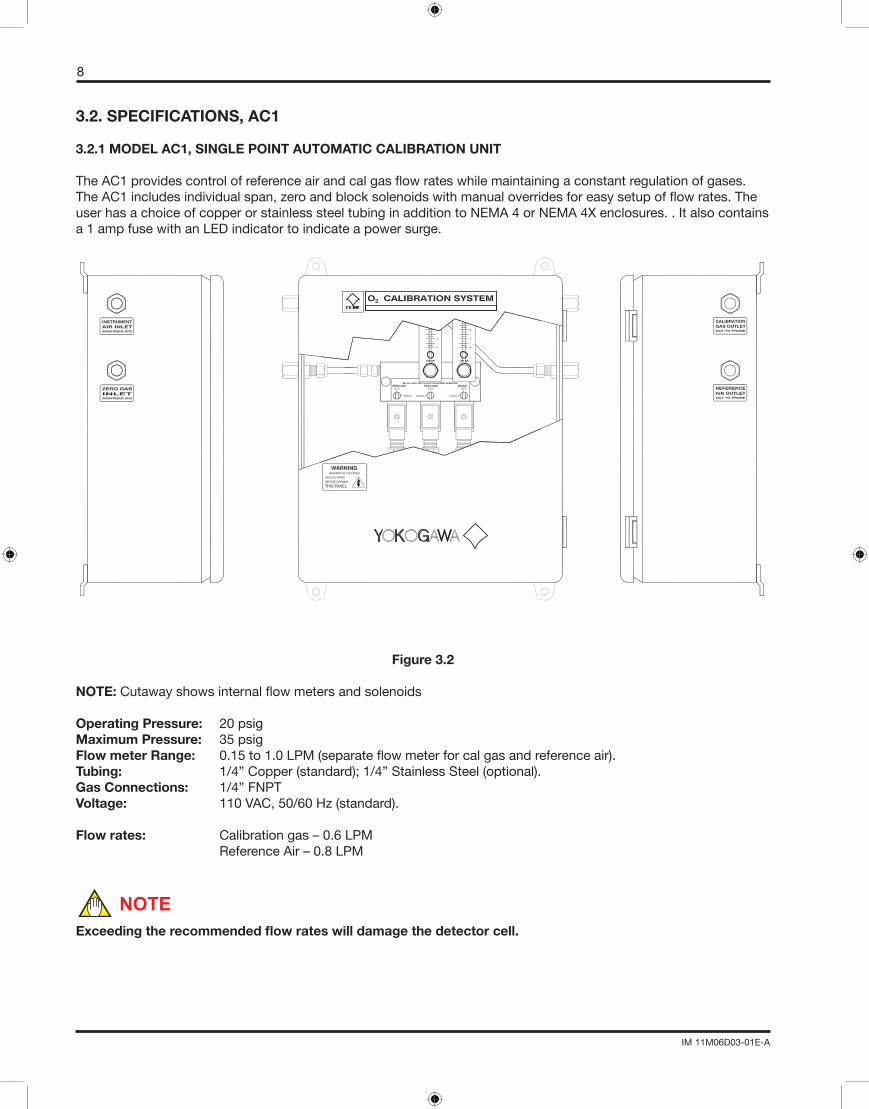
TheAC1providescontrolofreferenceairandcalgasflowrateswhilemaintainingaconstantregulationofgases.TheAC1includesindividualspan,zeroandblocksolenoidswithmanualoverridesforeasysetupofflowrates.TheuserhasachoiceofcopperorstainlesssteeltubinginadditiontoNEMA4orNEMA4Xenclosures..Italsocontainsa 1 amp fuse with an LED indicator to indicate a power surge.
Figure 3.2
NOTE: Cutawayshowsinternalflowmetersandsolenoids
Operating Pressure: 20 psigMaximum Pressure: 35 psigFlow meter Range: 0.15to1.0LPM(separateflowmeterforcalgasandreferenceair).Tubing: 1/4”Copper(standard);1/4”StainlessSteel(optional).Gas Connections: 1/4”FNPTVoltage: 110VAC,50/60Hz(standard).
Flow rates: Calibration gas – 0.6 LPM ReferenceAir–0.8LPM
Exceedingtherecommendedflowrateswilldamagethedetectorcell.
NOTE
9
IM 11M06D03-01E-A
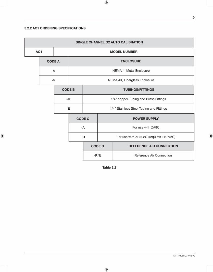
SINGLE CHANNEL O2 AUTO CALIBRATION
MODEL NUMBERAC1
ENCLOSURE
NEMA4,MetalEnclosure-4
CODE A
NEMA4X,FiberglassEnclosure-5
TUBINGS/FITTINGSCODE B
1/4”copperTubingandBrassFittings
1/4”StainlessSteelTubingandFittings
-C
-S
POWER SUPPLY
ForusewithZA8C-A
CODE C
ForusewithZR402G(requires110VAC)-D
REFERENCE AIR CONNECTION
Reference Air Connection-R*U
CODE D
3.2.2 AC1 ORDERING SPECIFICATIONS
Table 3.2
10
IM 11M06D03-01E-A
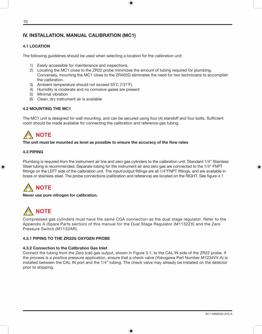
IV. INSTALLATION, MANUAL CALIBRATION (MC1)
4.1 LOCATION
Thefollowingguidelinesshouldbeusedwhenselectingalocationforthecalibrationunit:
1) Easily accessible for maintenance and inspections. 2) Locating the MC1 close to the ZR22 probe minimizes the amount of tubing required for plumbing. Conversely, mounting the MC1 close to the ZR402G eliminates the need for two technicians to accomplish the calibration. 3) Ambienttemperatureshouldnotexceed55˚C(131˚F). 4) Humidityismoderateandnocorrosivegasesarepresent 5) Minimal vibration 6) Clean, dry instrument air is available
4.2 MOUNTING THE MC1
TheMC1unitisdesignedforwallmounting,andcanbesecuredusingfour(4)standoffandfourbolts.Sufficientroom should be made available for connecting the calibration and reference gas tubing.
Theunitmustbemountedaslevelaspossibletoensuretheaccuracyoftheflowrates
4.3 PIPING
Plumbing is required from the instrument air line and zero gas cylinders to the calibration unit. Standard 1/4” Stainless Steeltubingisrecommended.Separatetubingfortheinstrumentairandzerogasareconnectedtothe1/4”FNPTfittingsontheLEFTsideofthecalibrationunit.Theinput/outputfittingsareall1/4”FNPTfittings,andareavailableinbrassorstainlesssteel.Theprobeconnections(calibrationandreference)arelocatedontheRIGHT.Seefigure4.1
Never use pure nitrogen for calibration.
Compressed gas cylinders must have the same CGA connection as the dual stage regulator. Refer to the AppendixA(SparePartssection)ofthismanualfortheDualStageRegulator(M1132ZX)andtheZeroPressure Switch (M1133AR).
4.3.1 PIPING TO THE ZR22G OXYGEN PROBE
4.3.2 Connection to the Calibration Gas InletConnectthetubingfromtheZero(cal)gasoutput,showninFigure3.1,totheCALINsideoftheZR22probe.Iftheprocessisapositivepressureapplication,ensurethatacheckvalve(YokogawaPartNumberM1234VV-A)isinstalledbetweentheCALINportandthe1/4”tubing.Thecheckvalvemayalreadybeinstalledonthedetectorprior to shipping.
NOTE
NOTE
NOTE
11
IM 11M06D03-01E-A
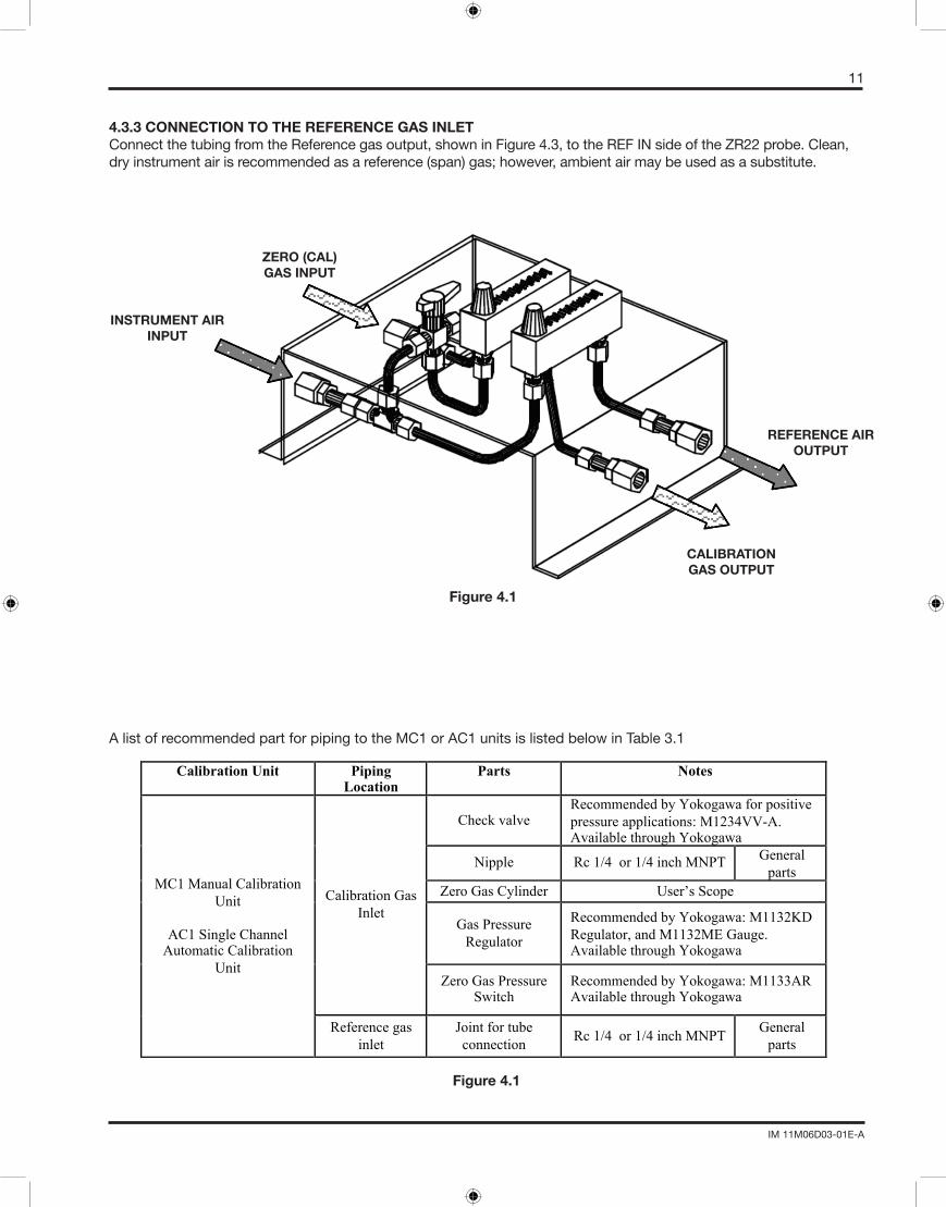
4.3.3 CONNECTION TO THE REFERENCE GAS INLETConnectthetubingfromtheReferencegasoutput,showninFigure4.3,totheREFINsideoftheZR22probe.Clean,dryinstrumentairisrecommendedasareference(span)gas;however,ambientairmaybeusedasasubstitute.
Figure 4.1
AlistofrecommendedpartforpipingtotheMC1orAC1unitsislistedbelowinTable3.1
Calibration Unit Piping Location
Parts Notes
Check valve Recommended by Yokogawa for positive
pressure applications: M1234VV-A. Available through Yokogawa
Nipple Rc 1/4 or 1/4 inch MNPT General
parts
Zero Gas Cylinder User’s Scope
Gas Pressure
Regulator
Recommended by Yokogawa: M1132KD
Regulator, and M1132ME Gauge. Available through Yokogawa
Calibration Gas
Inlet
Zero Gas Pressure Switch
Recommended by Yokogawa: M1133AR Available through Yokogawa
MC1 Manual Calibration
Unit
AC1 Single Channel Automatic Calibration
Unit
Reference gas
inlet
Joint for tube
connection Rc 1/4 or 1/4 inch MNPT
General
parts
INSTRUMENT AIRINPUT
ZERO (CAL)GAS INPUT
REFERENCE AIROUTPUT
CALIBRATION GAS OUTPUT
Figure 4.1
12
IM 11M06D03-01E-A
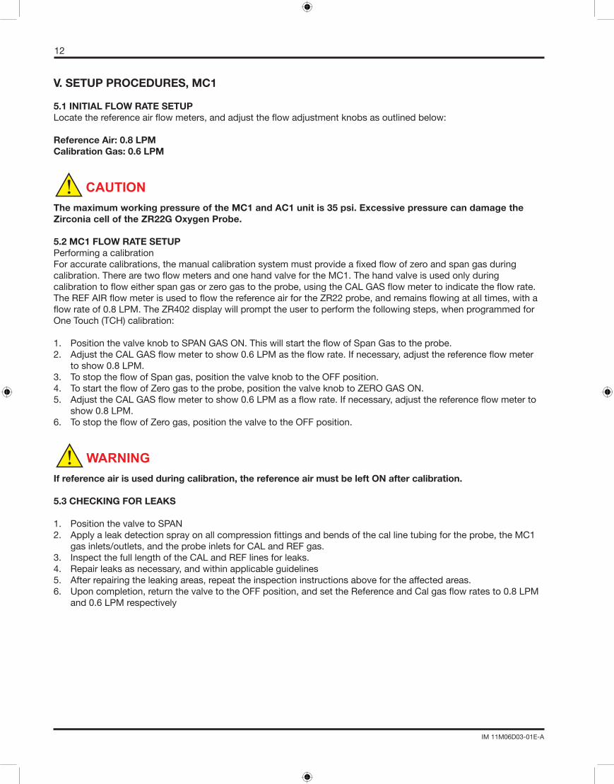
V. SETUP PROCEDURES, MC1
5.1 INITIAL FLOW RATE SETUPLocatethereferenceairflowmeters,andadjusttheflowadjustmentknobsasoutlinedbelow:
Reference Air: 0.8 LPMCalibrationGas:0.6LPM
The maximum working pressure of the MC1 and AC1 unit is 35 psi. Excessive pressure can damage the Zirconia cell of the ZR22G Oxygen Probe.
5.2 MC1 FLOW RATE SETUPPerforming a calibrationForaccuratecalibrations,themanualcalibrationsystemmustprovideafixedflowofzeroandspangasduringcalibration.TherearetwoflowmetersandonehandvalvefortheMC1.Thehandvalveisusedonlyduringcalibrationtofloweitherspangasorzerogastotheprobe,usingtheCALGASflowmetertoindicatetheflowrate.TheREFAIRflowmeterisusedtoflowthereferenceairfortheZR22probe,andremainsflowingatalltimes,withaflowrateof0.8LPM.TheZR402displaywillprompttheusertoperformthefollowingsteps,whenprogrammedforOneTouch(TCH)calibration:
1. PositionthevalveknobtoSPANGASON.ThiswillstarttheflowofSpanGastotheprobe.2. AdjusttheCALGASflowmetertoshow0.6LPMastheflowrate.Ifnecessary,adjustthereferenceflowmeter toshow0.8LPM.3. TostoptheflowofSpangas,positionthevalveknobtotheOFFposition.4. TostarttheflowofZerogastotheprobe,positionthevalveknobtoZEROGASON.5. AdjusttheCALGASflowmetertoshow0.6LPMasaflowrate.Ifnecessary,adjustthereferenceflowmeterto show0.8LPM.6. TostoptheflowofZerogas,positionthevalvetotheOFFposition.
If reference air is used during calibration, the reference air must be left ON after calibration.
5.3 CHECKING FOR LEAKS
1. PositionthevalvetoSPAN2. Applyaleakdetectionsprayonallcompressionfittingsandbendsofthecallinetubingfortheprobe,theMC1 gas inlets/outlets, and the probe inlets for CAL and REF gas. 3. Inspect the full length of the CAL and REF lines for leaks. 4. Repair leaks as necessary, and within applicable guidelines5. After repairing the leaking areas, repeat the inspection instructions above for the affected areas.6. Uponcompletion,returnthevalvetotheOFFposition,andsettheReferenceandCalgasflowratesto0.8LPM and 0.6 LPM respectively
CAUTION
WARNING
13
IM 11M06D03-01E-A
VI. INSTALLATION, AUTOMATIC CALIBRATION, AC1
6.1LOCATION
Thefollowingguidelinesshouldbeusedwhenselectingalocationforthecalibrationunit:
1) Easily accessible for maintenance and inspections.2) AsclosetotheZR22probeaspractical.Thiswillminimizetheamountoftubingrequiredforplumbing,and decreasecalibrationtimes.Ambienttemperatureshouldnotexceed55˚C(131˚F).3) Humidityismoderateandnocorrosivegasesarepresent
Use an air purge for the AC1 enclosure if the corrosive gases or high dust content is present.
4) Minimal vibration5) Clean, dry instrument air is available
6.2MOUNTINGTHEAC1
TheAC1isavailableinaNEMAandNEMA4X,lockableenclosure,andtheunitisdesignedforwallmounting.Itcanbe secured using four (4) standoffs and four (4) bolts. Mount the AC1 unit so that the terminal strip is easily visible for wiringpurposes.Sufficientroomshouldbemadeavailableforconnectingthecalibrationandreferencegastubing.
Theunitmustbemountedaslevelaspossibletoensuretheaccuracyoftheflowrates
6.3PIPING
AlistofrecommendedpartforpipingtotheMC1andAC1unitsislistedpreviouslyinTable4.1
6.3.1PIPINGTOTHEZR22GOXYGENPROBE
6.3.2CONNECTIONTOTHECALIBRATIONGASINLETConnectthetubingfromtheZero(cal)gasoutput,showninFigure5.1,totheCALINsideoftheZR22probe.Iftheprocessisapositivepressureapplication,ensurethatacheckvalve(YokogawaPartNumberM1234VV-A)isinstalledbetweentheCALINportandthe1/4”tubing.Thecheckvalvemayalreadybeinstalledonthedetectorprior to shipping.
6.3.3CONNECTIONTOTHEREFERENCEGASINLETConnectthetubingfromtheReferencegasoutput,showninFigure5.1,totheREFINsideoftheZR22probe.Clean,dryinstrumentairisrecommendedasareference(span)gas;however,ambientairmaybeusedasasubstitute.
6.4.WIRINGTOTHEAC1,AUTOMATICCALIBRATIONUNIT
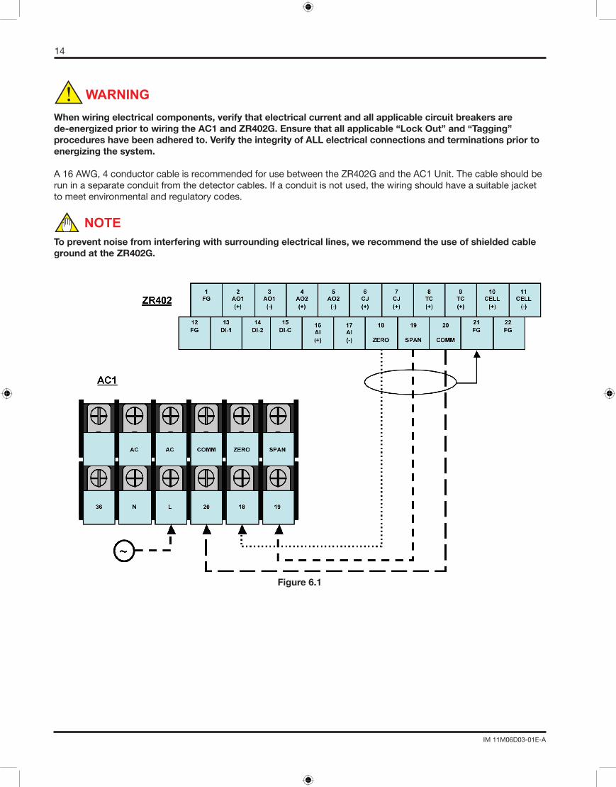
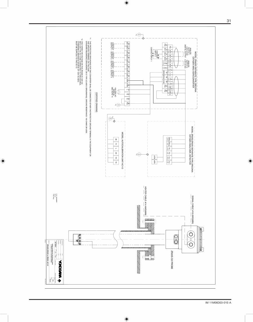
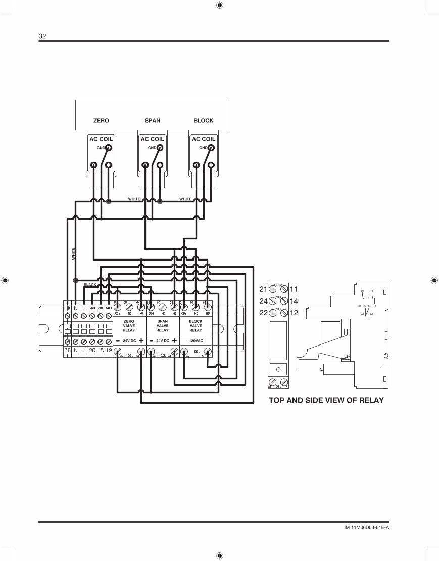
6.4.1WIRINGTHEAC1TOTHEZR22GThesolenoidsoftheAC1arepoweredby24VDCfromtheZR402GOxygenConverter.TheAC1itselfcanbepoweredbytheZR402GiftheZR402Gisusing120VAC,60Hz.SupplyvoltagefortheAC1canbeobtainedfromterminals“L,N&G”ontheZR402G.PleaserefertothewiringdiagramlocatedinAppendixC.
NOTE
NOTE
14
IM 11M06D03-01E-A
When wiring electrical components, verify that electrical current and all applicable circuit breakers are de-energized prior to wiring the AC1 and ZR402G. Ensure that all applicable “Lock Out” and “Tagging” procedures have been adhered to. Verify the integrity of ALL electrical connections and terminations prior to energizing the system.
A16AWG,4conductorcableisrecommendedforusebetweentheZR402GandtheAC1Unit.Thecableshouldberuninaseparateconduitfromthedetectorcables.Ifaconduitisnotused,thewiringshouldhaveasuitablejacketto meet environmental and regulatory codes.
To prevent noise from interfering with surrounding electrical lines, we recommend the use of shielded cable ground at the ZR402G.
Figure6.1
WARNING
NOTE
15
IM 11M06D03-01E-A
VII. SETUP PROCEDURES, AC1
Locatethereferenceairflowmeters,andadjusttheflowadjustmentknobsasoutlinedbelow:
Reference Air: 0.8 LPMCalibrationGas:0.6LPM
The maximum working pressure of the MC1 and AC1 unit is 35 psi. Excessive pressure can damage the Zirconia cell of the ZR22G Oxygen Probe.
7.1 INITIAL FLOW RATE SETUPEnsurethatthecalibrationgasandreferenceairlinesareproperlyplumbedtotheleftsideoftheAC1AutoCalUnit.Thezerogasandinstrumentairshouldbesetatapproximately20psi(±2psi).Powerisnotrequiredtosettheflowrates.
7.1.2 SETTING THE REFERENCE AIR FLOW RATESLocatethereferenceflowmeters.AdjusttheflowadjustmentknobontheREFERNCEAIRFLOWMETERto0.8LPMor800ml/min.
7.1.3 BALANCING PRESSURE DROPS IN THE CALIBRATION LINESForaccuratecalibrations,theautocalsystemmustprovideafixedflowofZerogasandSpangas.Tobalancethepressuredropsperformthefollowingsteps:
1) LocatetheBLOCKandSPANGASSOLENOID.Usingascrewdriver,turntheoverridescrewtothemanual position. See Figure 5.22) UsetheflowregulatorknobontheCALGASFLOWMETERtoadjusttheflowto1.0LPM.3) SwitchtheoverridescrewoftheSPANGASsolenoidtoAUTO.4) TurntheoverridescrewfortheZEROGASsolenoidtoMANUAL.5) Adjustthepressureregulatoronthezerogascylinderforaflowof1.0LPMontheCalibrationGasflowmeter.
DONOTUSEtheflowregulatorknoboftheflowmetertoachievethisflowlevel.
6) AdjusttheflowregulatorknobontheCalibrationGasflowmeteruntiltheflowmeterreads0.6LPM.7) VerifythatallthemanualoverridesaresetbacktoAUTO.
7.2 STANDARD OPERATION • TheReferenceAirFlowmeterindicates0.8LPMduringnormaloperationandcalibration. • AllmanualoverridesaresettotheAUTOposition. • TheCalibrationGasflowmeterwillshowaflowof0.6LPMduringCalibrationonly.
Before considering your calibration unit automated, it is good practice to check for leaks along the full distance of thecalibrationlinetubing,inadditiontoperformingaCALCHECKtoconfirmthatthegasesareplumbedcorrectlyto each probe.
CAUTION
CAUTION
16
IM 11M06D03-01E-A
7.3 CHECKING FOR LEAKS
Topreventleakage,allthreadedconnectionsshouldhaveTeflontape(orsuitablealternative)andallcompressionfittingsshouldbeinstalledpermanufacturer’srecommendations.
1. LocatetheBLOCKSOLENOID.TurntheoverridescrewontheBLOCKSOLENOIDandSPANSOLENOIDtothe manual position.2. Useleakdetectionsprayonallcompressionfittingsandbendsofthecalandreferencelinetubing.3. Inspect the full length of the tubing to determine if there is a leak.4. Repair leaks as necessary, and within applicable guidelines.5. After repairing the leaking areas, repeat the inspection instructions above for the affected areas.6. Uponcompletionofrepairingtheleaks,returnallsolenoidstotheAUTOposition.
NOTE
17
IM 11M06D03-01E-A
VIII. CALIBRATION SETUP & OPERATION, ZR402G
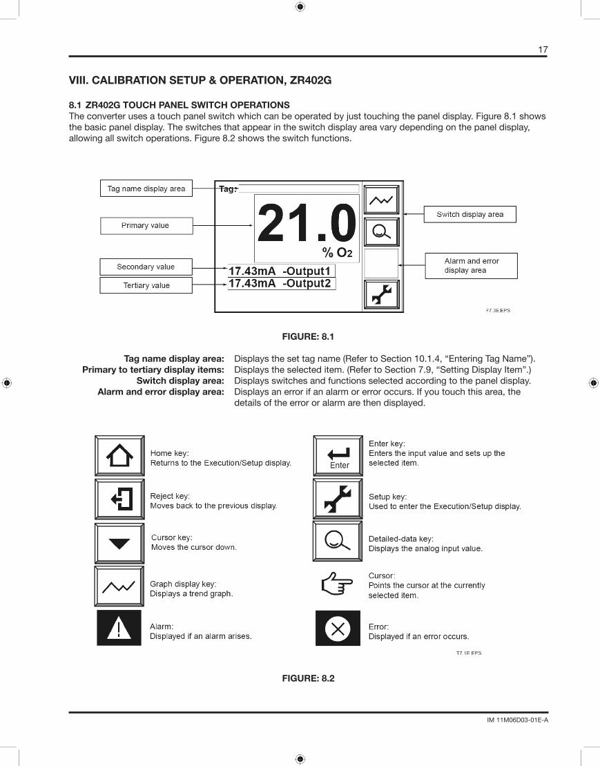
8.1 ZR402G TOUCH PANEL SWITCH OPERATIONSTheconverterusesatouchpanelswitchwhichcanbeoperatedbyjusttouchingthepaneldisplay.Figure8.1showsthebasicpaneldisplay.Theswitchesthatappearintheswitchdisplayareavarydependingonthepaneldisplay,allowingallswitchoperations.Figure8.2showstheswitchfunctions.
FIGURE: 8.1
Tag name display area: Displaysthesettagname(RefertoSection10.1.4,“EnteringTagName”). Primary to tertiary display items: Displaystheselecteditem.(RefertoSection7.9,“SettingDisplayItem”.) Switch display area: Displays switches and functions selected according to the panel display. Alarm and error display area: Displays an error if an alarm or error occurs. If you touch this area, the details of the error or alarm are then displayed.
FIGURE: 8.2
18
IM 11M06D03-01E-A
8.2 CALIBRATION
Theconverteriscalibratedinsuchawaythattheactualzeroandspangasesaremeasuredandthosemeasuredvaluesareusedtoagreewiththeoxygenconcentrationsintherespectivegases.Therearethreetypesofcalibrationproceduresavailable:
Manual calibration: conducting zero and span calibrations, or either of these calibrations in turn. Manual calibration needs the MC1 Manual Calibration Unit to allow manual supply of the calibration gases.
Semi-automatic calibration which uses the touch panel or a contact input signal and conducts calibration operations based on a preset calibration time and stable time.
Automatic calibration conducted at preset intervals. Semi-automatic and automatic calibration needs the AC1AutomaticCalibrationUnittoallowautomaticsupplyofthecalibrationgases.Thefollowingsectionsset forth the manual calibration procedures. For details on semi-automatic and automatic calibrations, consult Chapter9,“Calibration,”intheZR22G/ZR402GInstructionManual.
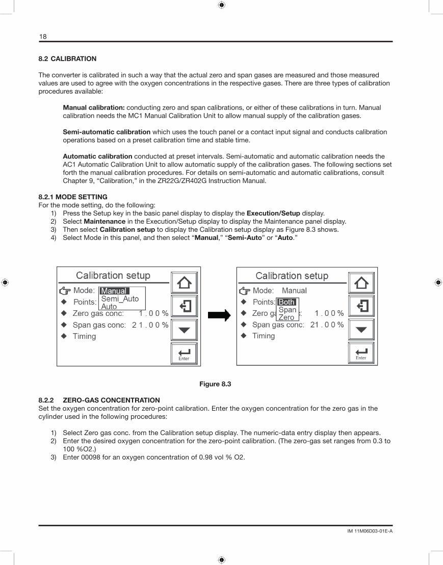
8.2.1 MODE SETTINGForthemodesetting,dothefollowing: 1) Press the Setup key in the basic panel display to display the Execution/Setup display. 2) Select Maintenance in the Execution/Setup display to display the Maintenance panel display. 3) ThenselectCalibration setuptodisplaytheCalibrationsetupdisplayasFigure8.3shows. 4) Select Mode in this panel, and then select “Manual,” “Semi-Auto” or “Auto.”
Figure 8.3
8.2.2 ZERO-GAS CONCENTRATIONSet the oxygen concentration for zero-point calibration. Enter the oxygen concentration for the zero gas in the cylinderusedinthefollowingprocedures:
1) SelectZerogasconc.fromtheCalibrationsetupdisplay.Thenumeric-dataentrydisplaythenappears. 2) Enterthedesiredoxygenconcentrationforthezero-pointcalibration.(Thezero-gassetrangesfrom0.3to 100%O2.) 3) Enter00098foranoxygenconcentrationof0.98vol%O2.

19
IM 11M06D03-01E-A
8.2.3 SPAN-GAS CONCENTRATION
Settheoxygenconcentrationforspancalibration.Ifinstrumentairisusedasthespangas,enter21%O2.
1) Select Span gas conc. from the Calibration setup display. 2) Enterthedesiredspan-gasoxygenconcentrationfromthenumeric-dataentrydisplay.(Thespan-gasset rangesfrom4.5to100%O2.) 3) Enter02100foranoxygenconcentrationof21vol%O2.Instrumentairisheredefinedasdryairwitha dew-pointtemperatureofnohigherthan-208˚C. Ifthedew-pointtemperatureishigherthan-208˚C,useahand-heldoxygenanalyzertomeasuretheactual oxygen concentration.
(1) When instrument air is used for the span calibration, remove the moisture from the instrument air at a dew-point temperature of -208C and also remove any oily mist and dust from that air.(2) If dehumidifying is not enough, or if foul air is used, the measurement accuracy will be adversely affected.
8.3 MANUAL CALIBRATIONFor manual calibration, consult Section 7.12, “Calibration,” In the ZR22G / ZR402G Instruction Manual (IM 11M12A01-02E)
8.4 SEMI-AUTOMATIC CALIBRATIONTostartcalibration,followthesesteps: (1) Press the Setup key in the basic panel display to display the Execution/Setup display. (2) ThenselectCalibrationfromtheExecution/Setupdisplay.TheCalibrationdisplayshowninFigure8.4 appears. (3) (2)SelectSemi-autocalibrationtodisplaytheSemi-automaticcalibrationdisplayshowninFigure8.4 (4) (3)SelectStartcalibration.ThedisplayshowninFigure8.4appears,andthenstartcalibration.
Figure 8.4
CAUTION
20
IM 11M06D03-01E-A
To start calibration using an input contact, follow these steps: (1) Make sure that Calibration start has been selected in the Input contacts display
(2) Apply an input contact to start calibration.
To stop calibration midway, follow these steps: (1) Press the Return key. If this key is pressed midway during calibration, the calibration will stop and the output stabilization time will be set up.
(2) Press the Return key once again to return to the basic panel display and the analyzer will be in normal measurement.
8.5 AUTOMATIC CALIBRATIONNoexecutionoperationsarerequiredforautomaticcalibration.Automaticcalibrationstartsinaccordancewithapreset start day and time. Calibration is then executed at preset intervals.
Before conducting a semi-automatic or automatic calibration, run the automatic calibration unit beforehand to obtain acalibrationflowof600±60ml/min.
CAUTION

21
IM 11M06D03-01E-A
APPENDIX ASPARE PART

22
IM 11M06D03-01E-A
MODEL MC1
1. M1132CC Flow meter, Brass (2) M1132ZC Flow Meter, SS (2) 2. M1132YL 3-WayBallValve(1) 3. M1132GC BRASS1/4”FNPTCONNECTION(4) M1132RS SS1/4”FNPTCONNECTION(4)
23
IM 11M06D03-01E-A
MODEL AC1
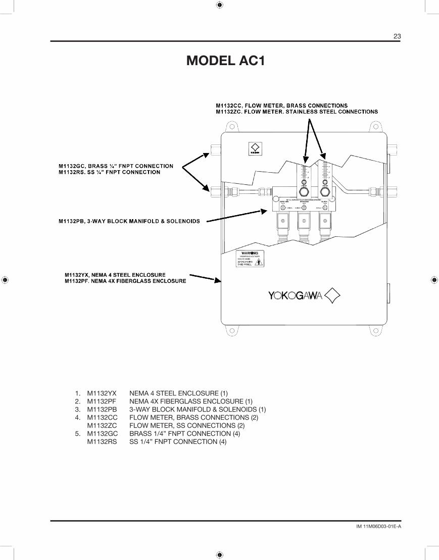
1. M1132YX NEMA4STEELENCLOSURE(1) 2. M1132PF NEMA4XFIBERGLASSENCLOSURE(1) 3. M1132PB 3-WAYBLOCKMANIFOLD&SOLENOIDS(1) 4. M1132CC FLOWMETER,BRASSCONNECTIONS(2) M1132ZC FLOWMETER,SSCONNECTIONS(2) 5. M1132GC BRASS1/4”FNPTCONNECTION(4) M1132RS SS1/4”FNPTCONNECTION(4)
24
IM 11M06D03-01E-A
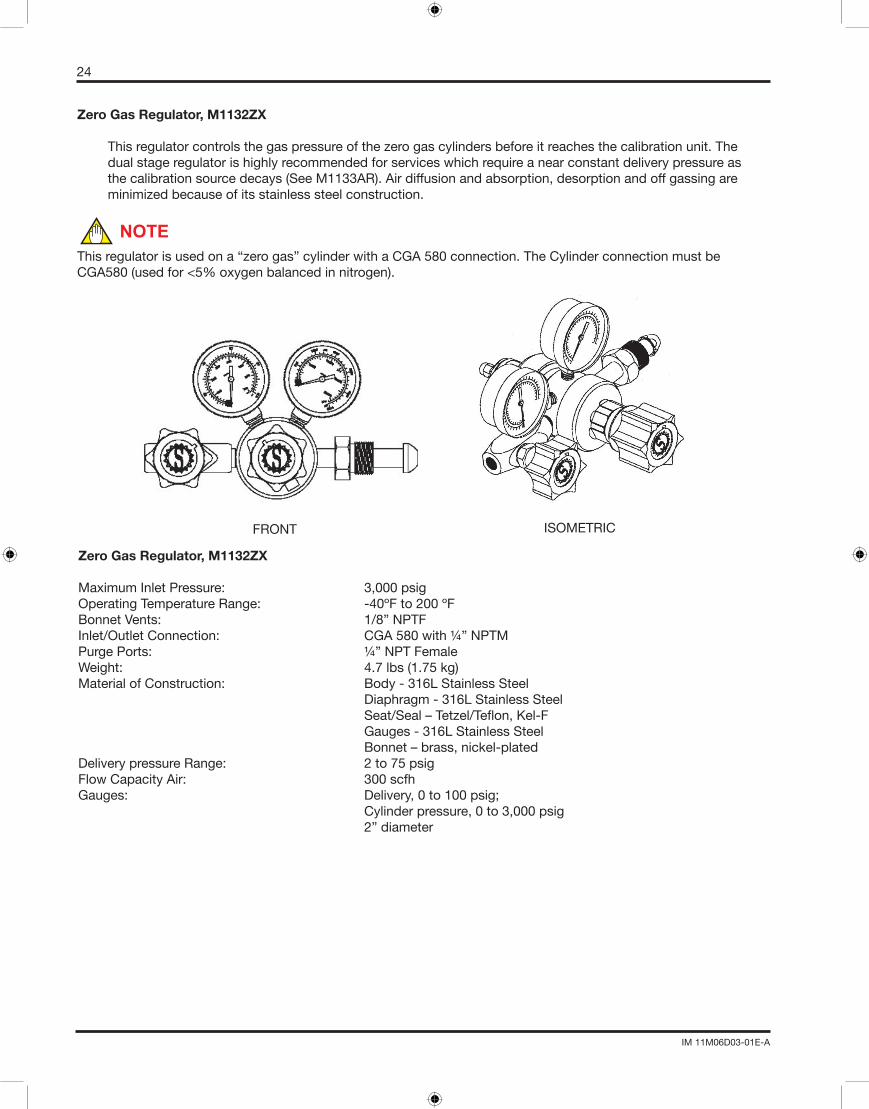
Zero Gas Regulator, M1132ZX Thisregulatorcontrolsthegaspressureofthezerogascylindersbeforeitreachesthecalibrationunit.The
dual stage regulator is highly recommended for services which require a near constant delivery pressure as the calibration source decays (See M1133AR). Air diffusion and absorption, desorption and off gassing are minimized because of its stainless steel construction.
NOTEThisregulatorisusedona“zerogas”cylinderwithaCGA580connection.TheCylinderconnectionmustbeCGA580(usedfor<5%oxygenbalancedinnitrogen).
Zero Gas Regulator, M1132ZX
MaximumInletPressure: 3,000psigOperatingTemperatureRange: -40ºFto200ºFBonnetVents: 1/8”NPTFInlet/OutletConnection: CGA580with¼”NPTMPurgePorts: ¼”NPTFemaleWeight: 4.7lbs(1.75kg)MaterialofConstruction: Body-316LStainlessSteel Diaphragm - 316L Stainless Steel Seat/Seal–Tetzel/Teflon,Kel-F
Gauges - 316L Stainless Steel Bonnet – brass, nickel-platedDeliverypressureRange: 2to75psigFlowCapacityAir: 300scfhGauges: Delivery,0to100psig; Cylinder pressure, 0 to 3,000 psig 2” diameter
FRONT ISOMETRIC

25
IM 11M06D03-01E-A
Zero Pressure Switch, M1133AR ThepressureswitchisusedtoalerttheOperatorviaacontactinputthatthezerogascylinderneedstobere-
placedbeforethecylinderisempty.Therecommendedconnectionistothehighpressuresideofthezerogasregulator. Refer to Figure 4.1.
Zero Pressure Switch, M1133AR
AdjustableSetPointRanges: 30to575psionfall;50to600psionrise.DeadBand: 8to60psiOverRange: 2,500psiProofPressure: 3,000psiStorageTemperature: -40ºFto180ºF(-40ºCto82ºC)AmbientTemperature: 0ºFto160ºF(-18ºCto71ºC)SetPointRepeatability: 1%ofspanSwitchOutput: OneSPDT(eitherNCorNO)ElectricalRating: Ratedto5ampsresistiveand15ampsinductive(75%PF),
at125and120VAC,¼”HPEnclosure: Aluminumwithirradiatefinishratedfor100hoursofsalt
sprayElectricalConnection: OneSPDToutput;½”NPTF,5ftcablePressureConnection: 1/8”NPTMMounting: NPTMpressureconnectionWeight: 12oz(340g)Approvals: UL508listed,E42272;CSAC22.2,No14-1987:LR9690

26
IM 11M06D03-01E-A
APPENDIX BDIMINSIONAL DRAWINGS
27
IM 11M06D03-01E-A
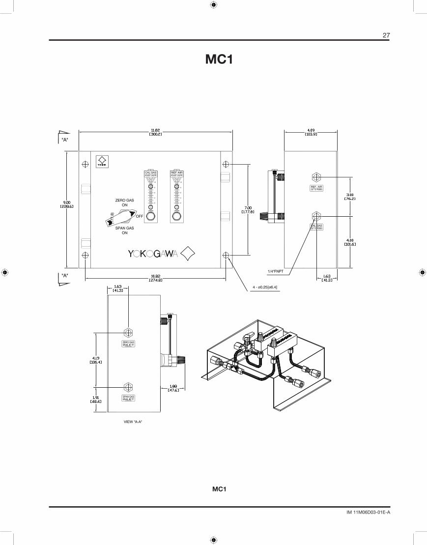
MC1
MC1
28
IM 11M06D03-01E-A
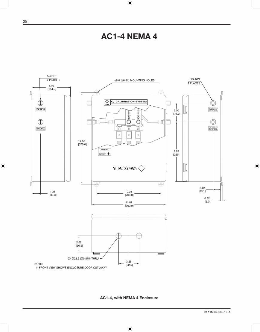
AC1-4 NEMA 4
AC1-4, with NEMA 4 Enclosure
29
IM 11M06D03-01E-A
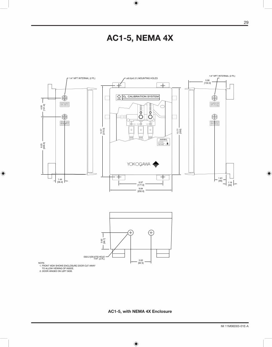
AC1-5, NEMA 4X
AC1-5, with NEMA 4X Enclosure

30
IM 11M06D03-01E-A
APPENDIX CWIRING DIAGRAM
31
IM 11M06D03-01E-A
32
IM 11M06D03-01E-A