Embed Size (px)
Citation preview

IM 05D01D12-01E (1)
This manual describes installation, wiring, and other tasks required to make the controller ready for operation.
Contents
1. Safety Precautions2. Model and Suffix Codes3. How to Install4. How to Connect Wires5. Hardware Specifications6. Terminal Wiring Diagrams
IntroductionThank you for purchasing the UT351/UT321 digital indicating controllers.The controller is shipped from the factory with 4 hardcopy user’s manuals (A2 and A3 size) and 1 user’s manual on CD-ROM. The 4 user’s manuals in hardcopy format describe the operating procedures required for basic use. It is recommendedthat you refer to these user’s manuals to understand [1] installation, [2] initial settings, and [3] operating procedures of thecontroller.The CD-ROM contains an User’s Manual (Reference) with descriptions of various functions and setting ranges that can beset as necessary.Moreover, the use of an optional parameter setting tool (model: LL100-E10) allows you to easily perform settings andadjustments with a PC.
■ How to Use the Manuals
Purpose Manual Title Description Media
SetupInstallation
Installation
Describes the tasks (installation, wiring, and others) requiredto make the controller ready for operations.
A2-size paper, back and front
Basic operation Initial Settings
Describes examples of setting PV input types, control outputtypes, and alarm types. Making settings described herein allows you to carry out basic control.
A2-size paper,front
Operating procedures and troubleshooting
Operations Describes key operation sequences. For operation control through external contact inputs, see the back ofUser’s Manual.
A2-size paper,back
Brief operationand setpoint recording
Parameters Contains the parameter map used as a guideline for settingparameters and lists of parameters for recording User Settings.
A2-size paper,back and front
Basic operation ofActive Color PV Display
Setting / explanation
of Active Color PV Display
Describes the setting/explanation of Active Color PV Display. A3-size paper,back and front
Detailed description of functions
User’s Manual (Reference)
Describes functions more advanced than those explained in the 3 hardcopy user’s manuals.
CD-ROM
1. Safety PrecautionsThe following symbol is indicated on the controller to ensure safe use.
CAUTION
This symbol on the controller indicates that the operator must refer to an explanation in the user’s manual in orderto avoid the risk of injury or death of personnel or damage to the instrument. The manual describes how the operatorshould exercise special care to avoid electric shock or other dangers that may result in injury or loss of life.
The following symbols are used in the hardcopy user’s manuals and in the user’s manual supplied on the CD-ROM.
NOTE
Indicates that operating the hardware or software in a particular manner may damage it or result in a system failure.
IMPORTANT
Draws attention to information that is essential for understanding the operation and/or features of the controller.
■ Exemption from ResponsibilityMake sure that all of the precautions are strictly adhered to. Yokogawa Electric Corporation assumes no liability for anydamage resulting from use of the instrument in contradiction to the precautions.Also, Yokogawa Electric Corporation assumes no liability to any party for any loss or damage, direct or indirect, causedby the use or any unpredictable defect of the instrument.■ Regarding Protection, Safety, and Prohibition Against Unauthorized Modification(1) In order to protect the product and the system controlled by it against damage and ensure its safe use, make certain that
all of the instructions and precautions relating to safety contained in this document are strictly adhered to. Yokogawadoes not guarantee safety if products are not handled according to these instructions.
(2) Modification of the product is strictly prohibited.
2. Model and Suffix CodesBefore using the controller, check that the model and suffix codes match your order.
UT351
UT321
0 None1 With communication, heater burnout alarmOptional functions2 With heater burnout alarm
-0 Standard type-2 Heating/cooling type-3 Standard type (with 24 V DC loop power supply)
Digital indicating controller (provided with retransmission output and 15 VDC loop power supply as standard)
Model Suffix Code Description
Type
Check that the following items are provided:• Digital indicating controller (of ordered model): ........................................... 1• Brackets (mounting hardware): ...................................................................... 1 pair• Unit label: ....................................................................................................... 1• User’s Manuals: .............................................................................................. 3 (A2 size)• User’s Manuals “Setting/Explanation of Active Color PV Display”: ............ 1 (A3 size)• User’s Manual (Reference) (CD-ROM version): ........................................... 1
3. How to Install
NOTE
To install the controller, select a location where:(1) no one may accidentally touch the terminals,(2) mechanical vibrations are minimal,(3) corrosive gas is minimal,(4) temperature can be maintained at about 23°C and the fluctuation is minimal,(5) no direct radiant heat is present,(6) no magnetic disturbances are caused,(7) no wind blows against the terminal board (reference junction compensation
element),(8) no water is splashed,(9) no flammable materials are around,
Never place the controller directly on flammable items or equipment.If the controller has to be installed close to flammable items or equipment, be sure to provide shielding panels allaround the controller, at least 150mm away from every side; the panels should be made of either 1.43mm-thickmetal-plated steel plates or 1.6mm-thick uncoated steel plates.
NOTE
Never touch the opening at the bottom of the case. It is to be used in the factory at shipping.
● Installation PositionInstall the controller at an angle within 30° from horizontalwith the front panel facing upward. Do not install it facingdownward. The position of right and left sides should be hori-zontal.
■ External Dimensions and Panel Cutout Dimensions
(25)
(53)
[(N-1)�96+92]117 min.
145 min.
+0.80
+0.
80
92
+0.8092
+0.8092
"N" stands for the number of controllers to be installed. However, the measured value applies if N � 5.
10011
UT351
Small bracket
Large bracket
91.8
112
Unit: mm
96
961 to 10 mm (Panel thickness)
General installation Side-by-side close installation
[(N-1)�48+45]+0.6
0
+0.
80
92
"N" stands for the number of controllers to be installed. However, the measured value applies if N � 5.
10048 11
UT321
Small bracket
Small bracket
91.8
96 112
Unit: mm
45 +0.60 (25)
(53) 145 min.
+0.8092
70 min.
1 to 10 mm (Panel thickness)
General installation Side-by-side close installation
■ How to Install
CAUTION
Turn off the power to the controller before installing it on the panel because there is a possibility of electric shock.
After opening the mounting hole on thepanel, follow the procedures below to in-stall the controller:1. Insert the controller into the opening
from the front of the panel so that theterminal board on the rear is at the farside.
2. Set the brackets in place on the top andbottom of the controller as shown in thefigure on the left, then tighten the screwsof the brackets. Take care not to over-tighten them.
4. How to Connect Wires
CAUTION
1) Before carrying out wiring, turn off the power to the controller and check that the cables to be connected are notalive with a tester or the like because there is a possibility of electric shock.
2) For the protection and safe use of the controller, be sure to place a circuit breaker (conforms with IEC60947,5A, 100V or 220V AC) near the controller where the breaker can easily be operated. In addition, be sure toindicate that it is the instrument to cut the power supply of the controller.
3) Wiring must be carried out by personnel who have basic electrical knowledge and practical experience.
NOTE
1) Provide power from a single-phase instrument power supply. If there is a lot of noise in the power line, insert aninsulating transformer into the primary side of the line and use a line filter (recommended part: ZAC2205-00Ufrom TDK) on the secondary side.As a countermeasures against noise, do not place the primary and secondary power cables close to each other.
2) For thermocouple input, use shielded compensating lead wires for wiring. For RTD input, use shielded wiresthat have low conductor resistance and cause no significant differences in resistance between the three wires.The cables to be used for wiring, terminal specifications, and recommended parts are as shown below.
3) Control output relays may be replaced. However, because they have a life of 100,000 times that of the resis-tance load, use auxiliary relays to turn on/off a load.
4) The use of inductance (L) loads such as auxiliary relays, motors and solenoid valves causes malfunction orrelay failure; always insert a CR filter for use with alternating current or a diode for use with direct current, asa spark-removal surge suppression circuit, into the line in parallel with the load.
5) When there is possibility of being struck by external lightening surge, use the arrester to protect the instrument.
■ For DC Relay Wiring ■ For AC Relay Wiring
R
UT351/UT321
UT’s contact
Diode(Mount it directly to the relay coil terminal (socket).)
External DC power supply
Relay(Use one with a relay coil rating
less than the UT’s contact rating.)
R
UT351/UT321
UT’s contact CR filter (Mount it directly to the relay coil terminal (socket).)
External AC power supply
Relay(Use one with a relay coil rating less than the UT’s
contact rating.)
● Cable Specifications and Recommended Cables
Purpose Name and Manufacturer
Power supply, grounding, relay contact outputs 600 V PVC insulated wires, JIS C 3307, 0.9 to 2.0 mm2
Thermocouple Shielded compensating lead wires, JIS C 1610, X- - - (See Yokogawa Electric's GS 6B1U1-E.)
RTD Shielded wires (three conductors), UL2482 (Hitachi Cable)
Other signals Shielded wires
● Recommended Terminal Lugs
3.7mm�
7 m
m o
r le
ss
3 .7mm�
7 m
m o
r le
ss
or
0.3 to 1.65 mm2 0.8 N·m or less
Applicable wire size Tightening torque
● Terminal Covers (Optional parts)
Target Model Part Number Sales Unit
For UT351 T9115YD 1
For UT321 T9115YE 1
5. Hardware SpecificationsPV Input Signals
• Number of inputs: 1 (terminals 11 - 12 - 13 )• Input type: Universal input system. The input type can be
selected with the software.• Sampling period: 250 ms• Burnout detection: Functions at TC, RTD, standard signal
(0.4 to 2 V or 1 to 5 V)Upscale, downscale, and off can be specified.For standard signal, burnout is determined to have occurredif it is 0.1 V or less.
• Input bias current: 0.05 �A (for TC or RTD b-terminal)• Measurement current (RTD): About 0.13 mA• Input resistance: 1 M� or more for thermocouple or mV input
About 1 M� for DC voltage input• Allowable signal source resistance: 250 � or less for
thermocouple or mV inputEffects of signal source resistance: 0.1 �V/� or less2 k� or less for DC voltage inputEffects of signal source resistance: About 0.01%/100 �
• Allowable wiring resistance: for RTD inputMaximum 150 �/wire: Conductor resistance between threewires should be equalHowever, 10 �/wire for a maximum range of -150.0 to150.0�C.Wire resistance effect: �0.1�C /10 �
• Allowable input voltage: �10 V DC for thermocouple, mV, orRTD input�20 V DC for DC voltage input
• Noise rejection ratio: 40 dB (50/60 Hz) or more in normal mode120 dB (50/60 Hz) or more in common mode
• Reference junction compensation error: �1.0�C (15 to 35�C)�1.5�C (0 to 15�C, 35 to 50�C)
• Applicable standards: JIS, IEC, DIN (ITS-90) for thermocouplesand RTD
Loop Power SupplySupplies power to a two-wire transmitter.(15 V DC: terminals 14 - 15 ; 24 V DC: terminals 21 - 22 )A resistor (10 to 250 �) connected between the controllerand transmitter converts a current signal into a voltagesignal, which is then read via the PV input terminal.Supply voltage: 14.5 to 18.0 V DC, max. 21 mA (providedwith a protection circuit against a field short-circuit); 21.6to 28.0 V DC, max. 30 mA (only for models with 24 V DCloop power supply)When using the 24 V DC loop power supply of the UT321,keep the operating ambient temperature between 0�C and40�C.
Retransmission OutputEither PV, target setpoint, or control output is output.Either the retransmission output or the 15 VDC loop powersupply can be used with terminals 14 - 15 .
• Number of outputs: 1 (terminals 14 - 15 )• Output signal: 4-20 mA DC• Load resistance: 600 � or less• Output accuracy: �0.3% of span under standard operating
conditions (23 �2�C, 55 �10% RH, power frequency of50/60 Hz)
Control OutputUniversal output system, The output type can be selectedwith the software.
• Current output (Standard type: terminals 16 - 17 ; Heating side:terminals 16 - 17 ; Cooling side: terminals 14 - 15 )
Number of outputs 1 or 2 (two for heating/cooling type), switched between a voltage pulse output
and current output.Output signal 4-20 mA DC
Load resistance 600 � or less
Output accuracy � 0.3% of span under standard operating conditions (23 � 2 �C, 55 �10% RH,
power frequency of 50/60 Hz)
• Voltage pulse output (Standard type: terminals 16 - 17 ; Heatingside: terminals 16 - 17 ; Cooling side: terminals 14 - 15 )
Number of outputs
1 or 2 (two for heating/cooling type), switched between a voltage pulse output and current output.
Output signal On-voltage = 12 V or more (load resistance: 600 � or more)Off-voltage = 0.1 V DC or less
Resolution 10 ms
• Relay contact output (Standard type: terminals 1 - 2 - 3 ; Heatingside: terminals 1 - 2 - 3 ; Cooling side: terminals 4 - 7 )
Number of outputs 1 or 2 (two for heating/cooling type)
Output signal Three terminals (NC, NO, and common) /Two terminals
Contact rating Terminals - - :250 V AC or 30 V DC, 3 A (resistance load)
Terminals - :240 V AC or 30 V DC, 1A (resistance load)
Resolution 10 ms
1 2 3
4 7
Contact Inputs• Purpose: Selection between target setpoints or Auto/Man modes,
or for other purposes• Number of inputs: 2• Input type: Non-voltage contact or transistor open collector input• Input contact rating: 12 V DC, 10 mA or more• On/off determination: For non-voltage contact input, contact
resistance of 1 k� or less is determined as “on” and contactresistance of 20 k� or more as “off.”For transistor open collector input, input voltage of 2 V orless is determined as “on” and leakage current must notexceed 100 �A when “off.”
• Minimum status detection hold time: About 1 second.
Contact Outputs• Purpose: Alarm output, FAIL output, and others• Number of outputs: 3• Relay contact rating: 240 V AC/1 A or 30 V DC/1 A ; 1a (COM
terminal is common), (FAIL output ; 1b)
Display Specifications• PV display:
UT351: 4-digit, 7-segment green or red LED display,character height of 20 mm
UT321: 4-digit, 7-segment green or red LED display,character height of 12 mm
• Setpoint display: 4-digit, 7-segment red LED display, characterheight of 9.3 mm (for both UT351 and UT321)
• Status indicating lamps: LEDs
Safety and EMC Standards• Safety: Complies with IEC/EN61010-1 (CE), approved by
C22.2 No.61010-1, approved by UL508.Installation category : CAT. II Pollution degree : 2 (IEC/EN61010-1, C22.2 No.61010-1)Measurement category : I (CAT. I : IEC/EN61010-1)Rated measurement input voltage : 10V DC max.(acrossterminals), 300V AC max.(across ground)Rated transient overvoltage : 1500V (Note)Note : It is a value on the safety standard which is assumedby IEC/EN61010-1 in Measurement category I, and is notthe value which guarantees an apparatus performance.
150mm150mm
150mm
150mm
Front panel of controller Must not
exceed 30�
30� Rear of controller
Large bracket (top mounting hardware)
Terminal board
Small bracket(bottom mounting hardware)
Panel
Recommended tightening torque:0.4N m
Insert a screwdriver into thebrackets to tighten the screws.
Direction to insert the controller
Insert the controller into the opening at the front of the panel.
User’sManual
IM 05D01D12-01E
Models UT351 / UT321Digital Indicating Controllerswith Active Color PV DisplayUser’s Manual Installation
6th Edition: Mar. 25, 2005
Fold the cover in the direction of the arrow.
Fit the cover hold over the protrusion on the mounting bracket.
Figure A
Figure B
1. Before attaching the terminal cover, bend the side withthe groove inward as shown in Fig. A. Be careful not tobend it backwards. This not only makes it harder toattach the cover but will also weaken its hold.
2. Fit the holes on the top and bottom of the terminal coverover the projections on the brackets (Fig. B) and lock inplace. The figure right shows the attachment of aterminal cover to UT controller.
CAUTION
This equipment has Measurement category I, there-fore do not use the equipment for measurementswithin Measurement categories II, III and IV.
1
2
3
4
Measurement category
CAT.1
CAT.2
CAT.3
CAT.4
Description
For measurements performed on circuits not directly connected to MAINS.For measurements performed on circuits directly connected to the low voltage installation.For measurements performed in the building installation.For measurements performed at the source of the low-voltage installation.
Remarks
Appliances, portable equipments, etc.
Distribution board, circuit breaker, etc.Overhead wire, cable systems, etc.
Internal Wiring
Outlet
EntranceCable
43
1T
2
• EMC standards: Complies with EN61326, EN61000-3-2,EN61000-3-3 and EN55011 (CE).AS/NZS 2064 compliant (C-Tick).Class A Group 1.The instrument continues to operate at a measuring accuracy ofwithin �20% of the range during tests.
Construction, Installation, and Wiring• Construction: Only the front panel is dust-proof and drip-proof
(protection class IP55)For side-by-side close installation the controller loses itsdust-proof and drip-proof protection.
• Material: ABS resin and polycarbonate• Case color: Black• Weight: About 1 kg or less• Dimensions:
UT351 96 (W) � 96 (H) � 100 (depth from panel face) mmUT321 48 (W) � 96 (H) � 100 (depth from panel face) mm
• Installation: Panel-mounting type. With top and bottommounting hardware (1 each)
• Panel cutout dimensions:UT351 92+0.8
0 (W) � 92+0.80 (H) mm
UT321 45+0.60 (W) � 92+0.8
0 (H) mm
• Installation position: Up to 30° upward facing(not designed for facing downward)
• Wiring: M3.5 screw terminals (for signal wiring and power/ground wiring as well)
Power Supply Specifications• Power supply: Rated voltage of 100 to 240 V AC (�10%), 50/60 Hz• Power consumption: Max. 20 VA (8.0 W max.)• Internal fuse rating: 250 V AC, 1.6A time-lug fuse• Data backup: Non-volatile memory (can be written to up to
100,000 times)• Withstanding voltage
- Between primary terminals* and secondary terminals**:At least 1500 V AC for 1 minute
- Between primary terminals* and grounding terminal:At least 1500 V AC for 1 minute
- Between grounding terminal and secondary terminals**:At least 1500 V AC for 1 minute
- Between secondary terminals**:At least 500 V AC for 1 minute
* Primary terminals indicate power terminals and relayoutput terminals
** Secondary terminals indicate analog I/O signal, voltagepulse output, and contact input terminals
• Insulation resistance: 20 M� or more at 500 V DC betweenpower terminals and grounding terminal
• Grounding: Class D grounding (grounding resistance of 100 �or less)
Signal Isolations• PV input terminals: Isolated from other input/output terminals.
Not isolated from the internal circuit.• 15 V DC loop power supply terminals: Not isolated from 4-20
mA analog output and voltage pulse control output. Isolatedfrom other input/output terminals and internal circuit.
• 24 V DC loop power supply terminals: Isolated from the 15 VDC loop power supply terminals, 4-20 mA analog outputterminals and voltage pulse control output terminals, otherI/O terminals and the internal circuitry.
• 4-20 mA analog output terminals (for control output andretransmission): Not isolated between 4-20 mA outputs norfrom 15 V DC loop power supply and voltage pulse controloutput. Isolated from other input/output terminals andinternal circuit.
• Voltage pulse control output terminals: Not isolated from 4-20mA outputs and 15 V DC loop power supply. Isolated fromother input/output terminals and internal circuit.
• Relay contact control output terminals: Isolated between contactoutput terminals and from other input/output terminals andinternal circuit.
• Contact input terminals: Not isolated between contact inputterminals and from communication terminals. Isolated fromother input/output terminals and internal circuit.
• Relay contact alarm output terminals: Not isolated betweenrelay contact alarm outputs. Isolated from other input/output terminals and internal circuit.
• RS-485 communication terminals: Not isolated from contactinput terminals. Isolated from other input/output terminalsand internal circuit.
• Power terminals: Isolated from other input/output terminals andinternal circuit.
• Grounding terminals: Isolated from other input/output terminalsand internal circuit.
Environmental Conditions• Normal operating conditions:
Ambient temperature: 0 to 50�C (40�C or less for side-by-sideclose installation)When using the 24 V DC loop power supply of the UT321, keepthe operating ambient temperature between 0�C and 40�C.
Temperature change rate: 10�C/h or lessAmbient humidity: 20 to 90% RH (no condensation allowed)Magnetic field: 400 A/m or lessContinuous vibration at 5 to 14 Hz: Full amplitude of 1.2 mm or lessContinuous vibration at 14 to 150 Hz: 4.9 m/s2 or lessShort-period vibration: 14.7 m/s2, 15 seconds or lessShock: 147 m/s2 or less, 11 msInstallation height: Height above sea level of 2000 m or lessWarm-up time: 30 minutes or more after power on
• Transportation and storage conditions:Temperature: -25 to 70�CTemperature change rate: 20�C/h or lessHumidity: 5 to 95% RH (no condensation allowed)
• Effects of changes in operating conditions- Effects from changes in ambient temperature:
- On voltage or thermocouple input, �1 �V/�C or �0.01%of F.S./�C, whichever is larger
- On RTD input, �0.05�C /�C (ambient temperature) or less- On analog output, �0.05% of F.S./�C or less
- Effects from power supply fluctuation (within rated voltagerange)
- On analog input, �1 �V/10 V or �0.01% of F.S./10 V,whichever is larger
- On analog output, �0.05% of F.S./ 10 V or less

IM 05D01D12-01E (2)
■ UT351 Standard Type (Model UT351-0� or UT351-3�) or Heating/Cooling type(Model UT351-2�)
1
2
Relay contact output
3
Control output
NC
NO
COM
Contact rating: 250 V AC, 3 A 30 V DC, 3 A (resistance load)
Note: Select this option from the OT parameter.
* Time proportional PID relay contact output is configured at factory before shipment.
23
24
RS-485 communication * Wiring can only be carried out for controllers with communication functions. Maximum baud rate: 9600 bps
25
26
27
SDB(+)
SDA(-)
RDB(+)
RDA(-)
SG
24 V DC loop power supply
* Wiring can only be carried out for controllers with 24 V DC loop power supply.
21.6-28.0VDC(30 mA DC max.)
21
22
+
-
12
13
TC input
11
12
RTD input
13
12
13
mV/V input
A
b
B-
+
-
+
Initial Settings User’s Manual
12
13
Note: Connecting a 250 � resistor to the terminals is optional.Model: X010-250-2 (resistor with M3.5 crimp-on terminal lugs)
* When receiving 4-20 mA DC current signals, set the PV input type to 1-5 V DC (setpoint “41”).
� Receiving 4-20 mA DC Current Signals with the Controller
250 � 4-20mA
PV input * Not configured at factory before shipment See ,
for more information.
-
+
14
15
Retransmission output
4-20 mA DC
14
15
15 V DC loop power supply
14.5-18.0VDC(21 mA DC max.)
* PV retransmission is configured at factory before shipment.
Load resistance: 600 � or less
* If 15 V DC loop power supply is used, retransmission output cannot be used.
-
+
-
+
16
17
Current / voltage pulse output
4-20 mA DC, voltage pulse (12 V)
Control output
+
-
Note:Select this option from the OT parameter.
6
5
Alarm output
4
7
AL1
AL2
AL3
COM
Relay contact rating: 240 V AC, 1 A 30 V DC, 1 A (resistance load)
Relay
Alarm-1 output
Alarm-2 output
Alarm-3 output
Common
UT
8
9
Power supply
10
L
N
Allowable range: 100 to 240 V AC (�10%)(free voltage) 50/60 Hz shared
Power supply CAUTION
21
22
23
24
25
26
27
28
29
30
11
12
13
14
15
16
17
18
19
20
1
2
3
4
5
6
7
8
9
10
Before carrying out wiring, turn off the power to the controller and check that cables to be connected are not alive with a tester or the like because there is a possibility of electric shock.
OT=0 (factory-set default)
Time proportional controlRelay output (terminals , and )
OT=1
Correspondence between parameter OT and control output types
Time proportional controlVoltage pulse output (terminals and )
OT=2
Current output (terminals and )
OT=3
On-off controlRelay output (terminals , and )
* OT is a setup parameter. You can change the settings of the parameter OT to change the control output type. See , for more information.Initial Settings User’s Manual
1 2 3 16 17 16 17 1 2 3
When switching target setpoints 1 to 4:
DI1
DI2
1.SP2.SP3.SP4.SP
OFF
OFFOFF
ON ON
ON
OFF
ON
Contact rating: 12 V DC, 10 mA or more
Correspondence between parameter DIS and external contact input functions
When DIS=4
DI1
DI2
COMCommon
When DIS=3
2.SP when DI1=ON 1.SP when DI1=OFF
STOP when DI2=ON RUN when DI2=OFF
Common
When DIS=2
Hides the LOCK parameter when DI1=ON.Shows the LOCK parameter when DI1=OFF.
Common
When DIS=1 (Factory-set default)
2.SP when DI1=ON 1.SP when DI1=OFF
AUTO when DI2=ONMAN when DI2=OFF
Common
When DIS=OFF
No function
No function
Common
DI1
DI2
COM
+5V
+5V
Contact Transistor contact
* DIS is a setup parameter. Changing DIS setpoint allows you to change the function of external contact input.
* This wiring is only possible for a controller with a heater burnout alarm. 29
28
Heater current detection input
30
CT2
CT1
COM
CT
CTNo function
19
18
20
UT
19
18
20
Note: External Contact InputIf the power is turned on when the external contact input is OFF, the mode (SP.no or A/M) existing before the power is turned off will be continued. (except for RUN/STOP)
■ UT351 Heating/Cooling Type (Model UT351-2�)
Heating-side control output
1
2
3
NC
NO
COM
Relay contact output * Time proportional PID relay contact output is configured at factory before shipment.* Available if 4, 7 or 10 is set in the OT (Control Output Type) setup parameter.
Contact rating: 250 V AC, 3 A 30 V DC, 3 A (resistance load)
23
24
25
26
27
SDB(+)
SDA(-)
RDB(+)
RDA(-)
SG
* Wiring can only be carried out for controllers with communication functions. Maximum baud rate: 9600 bps
RS-485 communication
12
13
11
12
13
12
13
A
b
B
+
-
+
-
TC input RTD input
mV/V input
12
13
* When receiving 4-20 mA DC current signals, set the PV input type to 1-5 V DC (setpoint “41”).
� Receiving 4-20 mA DC Current Signals with the Controller
250 � 4-20mA
-
+
Note: Connecting a 250 � resistor to the terminals is optional.Model: X010-250-2 (resistor with M3.5 crimp-on terminal lugs)
Initial Settings User’s ManualPV input * Not configured at factory before shipment
See , for more information.
Heating-side control output
16
17
Current / voltage pulse output
4-20 mA DC, voltage pulse(12 V)
+
-
* Available if 5, 6, 8, 9, 11 or 12 is set in the OT (Control Output Type) setup parameter.
14
15
14
15
+
-
+
-
Retransmission output
4-20 mA DC
15 V DC loop power supply
14.5-18.0VDC(21 mA DC max.)
14
15
+
-
Cooling-side control output
4-20 mA DC,voltage pulse (12 V) 8
9
10
L
N
CAUTIONBefore carrying out wiring, turn off the power to the controller and check that cables to be connected are not alive with a tester or the like because there is a possibility of electric shock.
Power supply
Power supply
Allowable range: 100 to 240 V AC (�10%)(free voltage) 50/60 Hz shared
6
5
4
7
AL1
AL2
AL3
COM
Relay
Alarm output/cooling-side control output
Alarm-1 output
Alarm-2 output
Alarm-3 output or cooling-side control
output (Note)
Common
Relay contact rating: 240 V AC, 1 A 30 V DC, 1 A (resistance load)
UT
When switching target setpoints 1 to 4:
DI1
DI2
1.SP2.SP3.SP4.SP
OFF
OFFOFF
ON ON
ON
OFF
ON
Contact rating: 12 V DC, 10 mA or more
Correspondence between parameter DIS and external contact input functions
When DIS=4
DI1
DI2
COMCommon
When DIS=3
2.SP when DI1=ON 1.SP when DI1=OFF
STOP when DI2=ON RUN when DI2=OFF
Common
When DIS=2
Hides the LOCK parameter when DI1=ON.Shows the LOCK parameter when DI1=OFF.
Common
When DIS=1 (Factory-set default)
2.SP when DI1=ON 1.SP when DI1=OFF
AUTO when DI2=ONMAN when DI2=OFF
Common
When DIS=OFF
No function
No function
Common
DI1
DI2
COM
+5V
+5V
Contact Transistor contact
* DIS is a setup parameter. Changing DIS setpoint allows you to change the function of external contact input.
No function
19
18
20
UT
19
18
20
OT=4 (factory-set default) OT=5
Correspondence between parameter OT and heating-side/cooling-side output types
OT=6 OT=7 OT=8 OT=9 OT=10 OT=11 OT=12
* OT is a setup parameter. You can change the settings of the parameter OT to change the control output type. See , for more information.
The control output types, “relay output” and “voltage pulse output” shown in the table above refer to those of time proportional control. To change the type to a relay output for on-off control, select “Relay Terminals” and change the setpoint of the proportional band to “0.”
Heating side: Relay output(terminals , and )
Cooling side: Relay output(terminals and )
1 2 3Heating side: Voltage pulse output
(terminals and )Cooling side: Relay output
(terminals and )
16 17Heating side: Current output
(terminals and )Cooling side: Relay output
(terminals and )
16 17
14 15 14 15 14 15 14 15 14 15 14 15
Heating side: Relay output(terminals , and )
Cooling side: Voltage pulse output(terminals and )
1 2 3Heating side: Relay output
(terminals , and )Cooling side: Current output
(terminals and )
1 2 3Heating side: Voltage pulse output
(terminals and )Cooling side: Voltage pulse output
(terminals and )
16 17Heating side: Current output
(terminals and )Cooling side: Voltage pulse output
(terminals and )
16 17Heating side: Voltage pulse output
(terminals and )Cooling side: Current output
(terminals and )
16 17Heating side: Current output
(terminals and )Cooling side: Current output
(terminals and )
16 17
Initial Settings User’s Manual
4 7 4 7 4 7
21
22
23
24
25
26
27
28
29
30
11
12
13
14
15
16
17
18
19
20
1
2
3
4
5
6
7
8
9
10
Note: The cooling-side control output is selected if 4, 5 or 6 is set in the OT (Control Output Type) setup parameter. The alarm-3 output is not available. The controller is factory-set to the cooling-side control output (time proportional PID relay contact output).
* PV retransmission is configured at factory before shipment.
* If 15 V DC loop power supply is used, retransmission output cannot be used.
* The retransmission output and 15 V DC loop power supply are not available if the cooling-side control output is set to “current output” and “voltage pulse output.”
29
28
Heater current detection input
30
CT2
CT1
COM
CT
CT
* This wiring is only possible for a controller with a heater burnout alarm.
Note: External Contact InputIf the power is turned on when the external contact input is OFF, the mode (SP.no or A/M) existing before the power is turned off will be continued. (except for RUN/STOP)
6. Terminal Wiring Diagrams
■ UT321 Standard Type (Model UT321-0� or UT321-3�) or Heating/Cooling type(Model UT321-2�)
1
2
Relay contact output
3
Control output
NC
NO
COM
Contact rating: 250 V AC, 3 A 30 V DC, 3 A (resistance load)
Note: Select this option from the OT parameter.
* Time proportional PID relay contact output is configured at factory before shipment. 23
24
RS-485 communication * Wiring can only be carried out for controllers with
communication functions. Maximum baud rate: 9600 bps
25
26
27
SDB(+)
SDA(-)
RDB(+)
RDA(-)
SG
24 V DC looppower supply
* Wiring can only be carried out for controllers with 24 V DC loop power supply.
21.6-28.0VDC(30 mA DC max.)
21
22
+
-
8
9
Power supply
10
L
N
Allowable range: 100 to 240 V AC (�10%)(free voltage) 50/60 Hz shared
Power supply CAUTIONBefore carrying out wiring, turn off the power to the controller and check that cables to be connected are not alive with a tester or the like because there is a possibility of electric shock.
6
5
Alarm output
4
7
AL1
AL2
AL3
COM
Relay contact rating: 240 V AC, 1 A 30 V DC, 1 A (resistance load)
Relay
Alarm-1 output
Alarm-2 output
Alarm-3 output
Common
UT
16
17
Current / voltage pulse output
4-20 mA DC, voltage pulse (12 V)
Control output
+
-
Note:Select this option from the OT parameter.
12
13
TC input
11
12
RTD input
13
12
13
mV/V input
A
b
B-
+
-
+
Initial Settings User’s Manual
12
13
Note: Connecting a 250 � resistor to the terminals is optional.Model: X010-250-2 (resistor with M3.5 crimp-on terminal lugs)
* When receiving 4-20 mA DC current signals, set the PV input type to 1-5 V DC (setpoint “41”).
� Receiving 4-20 mA DC Current Signals with the Controller
250 � 4-20mA
PV input * Not configured at factory before shipment See ,
for more information.
-
+
14
15
Retransmission output
4-20 mA DC
14
15
15 V DC loop power supply
14.5-18.0VDC(21 mA DC max.)
* PV retransmission is configured at factory before shipment.
Load resistance: 600 � or less
* If 15 V DC loop power supply is used, retransmission output cannot be used.
-
+
-
+
* This wiring is only possible for a controller with a heater burnout alarm. 29
28
Heater current detection input
30
CT2
CT1
COM
CT
CT
OT=0 (factory-set default)
Time proportional controlRelay output (terminals , and )
OT=1
Correspondence between parameter OT and the control output types
Time proportional controlVoltage pulse output (terminals and )
OT=2
Current output (terminals and )
OT=3
On-off controlRelay output (terminals , and )
* OT is a setup parameter. You can change the settings of the parameter OT to change the control output type. See , for more information.Initial Settings User’s Manual
1 2 3 16 17 16 17 1 2 3
When switching target setpoints 1 to 4:
DI1
DI2
1.SP2.SP3.SP4.SP
OFF
OFFOFF
ON ON
ON
OFF
ON
Contact rating: 12 V DC, 10 mA or more
Correspondence between parameter DIS and external contact input functions
When DIS=4
DI1
DI2
COMCommon
When DIS=3
2.SP when DI1=ON 1.SP when DI1=OFF
STOP when DI2=ON RUN when DI2=OFF
Common
When DIS=2
Hides the LOCK parameter when DI1=ON.Shows the LOCK parameter when DI1=OFF.
Common
When DIS=1 (Factory-set default)
2.SP when DI1=ON 1.SP when DI1=OFF
AUTO when DI2=ONMAN when DI2=OFF
Common
When DIS=OFF
No function
No function
Common
DI1
DI2
COM
+5V
+5V
Contact Transistor contact
* DIS is a setup parameter. Changing DIS setpoint allows you to change the function of external contact input.
No function
19
18
20
UT
19
18
20
1
2
3
4
5
6
7
8
9
10
21
22
23
24
25
26
27
28
29
30
11
12
13
14
15
16
17
18
19
20
Note: External Contact InputIf the power is turned on when the external contact input is OFF, the mode (SP.no or A/M) existing before the power is turned off will be continued. (except for RUN/STOP)
■ UT321 Heating/Cooling Type (Model UT321-2�)
Heating-side control output
1
2
3
NC
NO
COM
Relay contact output * Time proportional PID relay contact output is configured at factory before shipment. * Available if 4, 7 or 10 is set in the OT (Control Output Type) setup parameter.
Contact rating: 250 V AC, 3 A 30 V DC, 3 A (resistance load)
23
24
25
26
27
SDB(+)
SDA(-)
RDB(+)
RDA(-)
SG
* Wiring can only be carried out for controllers with communication functions. Maximum baud rate: 9600 bps
RS-485 communication
12
13
11
12
13
12
13
A
b
B
+
-
+
-
TC input RTD input
mV/V input
12
13
* When receiving 4-20 mA DC current signals, set the PV input type to 1-5 V DC (setpoint “41”).
� Receiving 4-20 mA DC Current Signals with the Controller
250 � 4-20mA
-
+
Note: Connecting a 250 � resistor to the terminals is optional.Model: X010-250-2 (resistor with M3.5 crimp-on terminal lugs)
Initial Settings User’s ManualPV input * Not configured at factory before shipment
See , for more information.
14
15
14
15
+
-
+
-
Retransmission output
4-20 mA DC
15 V DC loop power supply
14.5-18.0VDC(21 mA DC max.)
Cooling-side control output
4-20 mA DC,voltage pulse (12 V)
* PV retransmission is configured at factory before shipment.
* If 15 V DC loop power supply is used, retransmission output cannot be used.
* The retransmission output and 15 V DC loop power supply are not available if the cooling-side control output is set to “current output” and “voltage pulse output.”
Heating-side control output
16
17
Current / voltage pulse output
4-20 mA DC, voltage pulse(12 V)
+
-
* Available if 5, 6, 8, 9, 11 or 12 is set in the OT (Control Output Type) setup parameter.
When switching target setpoins 1 to 4:
DI1
DI2
1.SP2.SP3.SP4.SP
OFF
OFFOFF
ON ON
ON
OFF
ON
Contact rating: 12 V DC, 10 mA or more
Correspondence between parameter DIS and external contact input functions
When DIS=4
DI1
DI2
COMCommon
When DIS=3
2.SP when DI1=ON 1.SP when DI1=OFF
STOP when DI2=ON RUN when DI2=OFF
Common
When DIS=2
Hides the LOCK parameter when DI1=ON.Shows the LOCK parameter when DI1=OFF.
Common
When DIS=1 (Factory-set default)
2.SP when DI1=ON 1.SP when DI1=OFF
AUTO when DI2=ONMAN when DI2=OFF
Common
When DIS=OFF
No function
No function
Common
DI1
DI2
COM
+5V
+5V
Contact Transistor contact
* DIS is a setup parameter. Changing DIS setpoint allows you to change the function of external contact input.
No function
19
18
20
UT
19
18
20
Note: The cooling-side control output is selected if 4, 5 or 6 is set in the OT (Control Output Type) setup parameter. The alarm-3 output is not available. The controller is factory-set to the cooling-side control output (time proportional PID relay contact output).
8
9
10
L
N
CAUTIONBefore carrying out wiring, turn off the power to the controller and check that cables to be connected are not alive with a tester or the like because there is a possibility of electric shock.
Power supply
Power supply
Allowable range: 100 to 240 V AC (�10%)(free voltage) 50/60 Hz shared
29
28
Heater current detection input
30
CT2
CT1
COM
CT
CT
* This wiring is only possible for a controller with a heater burnout alarm.
OT=4 (factory-set default) OT=5 OT=6
* OT is a setup parameter. You can change the settings of the parameter OT to change the control output type. See , for more information.
Heating side: Relay output(terminals , and )
Cooling side: Relay output(terminals and )
1 2 3Heating side: Voltage pulse output
(terminals and )Cooling side: Relay output
(terminals and )
16 17Heating side: Current output
(terminals and )Cooling side: Relay output
(terminals and )
16 17
Initial Settings User’s Manual
Correspondence between parameter OT and heating-side/cooling-side output types
OT=7 OT=8 OT=9
Heating side: Relay output(terminals , and )
Cooling side: Voltage pulse output(terminals and )
1 2 3Heating side: Voltage pulse output
(terminals and )Cooling side: Voltage pulse output
(terminals and )
16 17Heating side: Current output
(terminals and )Cooling side: Voltage pulse output
(terminals and )
16 17
OT=10 OT=11 OT=12
The control output types, “relay output” and “voltage pulse output” shown in the table above refer to those of time proportional control. To change the type to a relay output for on-off control, select “Relay Terminals” and change the setpoint of the proportional band to “0.”
Heating side: Relay output(terminals , and )
Cooling side: Current output(terminals and )
1 2 3Heating side: Voltage pulse output
(terminals and )Cooling side: Current output
(terminals and )
16 17Heating side: Current output
(terminals and )Cooling side: Current output
(terminals and )
16 17
12
13
14
15
100�
Two-wire transmitter
PV input 0.4 to 2.0 V DC signal
Loop power supply
14.5 to 18.0 V DC
External resistor (Note)
Note: Connecting a 100 � resistor to the terminals is optional. Model: X010-100-2 (resistor with M3.5 crimp-on terminal lugs)
15 V DC Power Supply Wiring to Two-wire Sensor
4-20mADC
12
13
21
22
250�
Two-wire transmitter
PV input 1 to 5 V DC signal
Loop power supply
21.6 to 28.0 V DC
External resistor (Note)
Note: Connecting a 250 � resistor to the terminals is optional. Model: X010-250-2 (resistor with M3.5 crimp-on terminal lugs)
24 V DC Power Supply Wiring to Two-wire Sensor
* Wiring can only be carried out for controllers with 24 V DC loop power supply.
4-20mADC
1
2
3
4
5
6
7
8
9
10
21
22
23
24
25
26
27
28
29
30
11
12
13
14
15
16
17
18
19
20
6
5
4
7
AL1
AL2
AL3
COM
Relay
Alarm output/cooling-side control output
Alarm-1 output
Alarm-2 output
Alarm-3 output or cooling-side control
output (Note)
Common
Relay contact rating: 240 V AC, 1 A 30 V DC, 1 A (resistance load)
UT
4 7 4 7 4 7
14 15 14 15 14 15
14 1514 1514 15
Note: External Contact InputIf the power is turned on when the external contact input is OFF, the mode (SP.no or A/M) existing before the power is turned off will be continued. (except for RUN/STOP)
14
15
+
-
NOTE
Do not use unassigned terminals as relay terminals.
IM 05D01D12-02E (1)
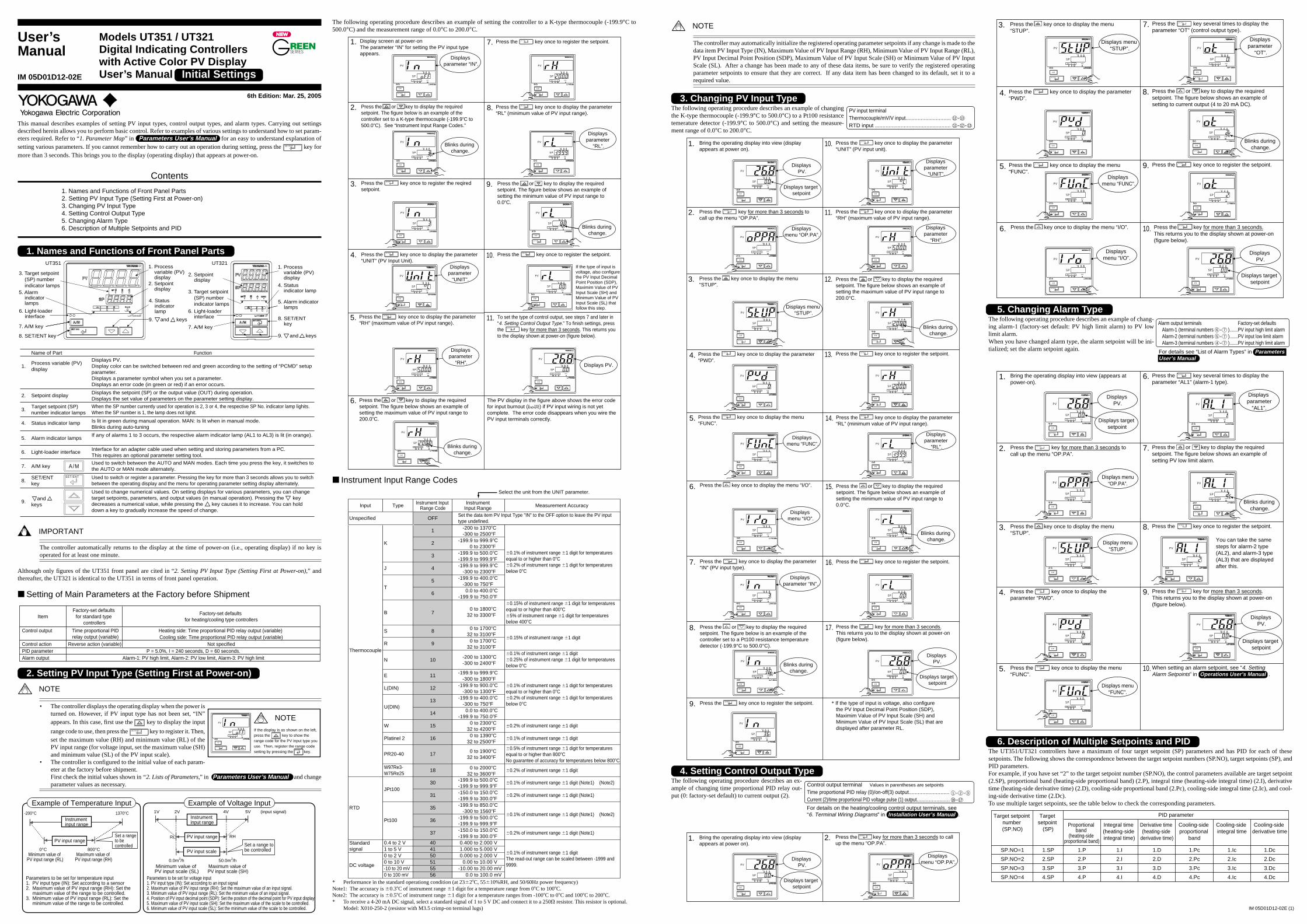
This manual describes examples of setting PV input types, control output types, and alarm types. Carrying out settingsdescribed herein allows you to perform basic control. Refer to examples of various settings to understand how to set param-eters required. Refer to “1. Parameter Map” in Parameters User’s Manual for an easy to understand explanation ofsetting various parameters. If you cannot remember how to carry out an operation during setting, press the SET/ENT key formore than 3 seconds. This brings you to the display (operating display) that appears at power-on.
Contents
1. Names and Functions of Front Panel Parts2. Setting PV Input Type (Setting First at Power-on)3. Changing PV Input Type4. Setting Control Output Type5. Changing Alarm Type6. Description of Multiple Setpoints and PID
1. Names and Functions of Front Panel Parts
Name of Part Function
7. A/M key Used to switch between the AUTO and MAN modes. Each time you press the key, it switches to the AUTO or MAN mode alternately.
8.SET/ENT key
S E T / E N T Used to switch or register a parameter. Pressing the key for more than 3 seconds allows you to switch between the operating display and the menu for operating parameter setting display alternately.
9.
Used to change numerical values. On setting displays for various parameters, you can change target setpoints, parameters, and output values (in manual operation). Pressing the key decreases a numerical value, while pressing the key causes it to increase. You can hold down a key to gradually increase the speed of change.
A /M
and keys
1.Process variable (PV) display
Displays PV. Display color can be switched between red and green according to the setting of “PCMD” setup parameter.Displays a parameter symbol when you set a parameter. Displays an error code (in green or red) if an error occurs.
2. Setpoint display Displays the setpoint (SP) or the output value (OUT) during operation.Displays the set value of parameters on the parameter setting display.
3.Target setpoint (SP)number indicator lamps
When the SP number currently used for operation is 2, 3 or 4, the respective SP No. indicator lamp lighits.When the SP number is 1, the lamp does not lighit.
4. Status indicator lamp Is lit in green during manual operation. MAN: Is lit when in manual mode.Blinks during auto-tuning
5. Alarm indicator lampsIf any of alarms 1 to 3 occurs, the respective alarm indicator lamp (AL1 to AL3) is lit (in orange).
6. Light-loader interface Interface for an adapter cable used when setting and storing parameters from a PC. This requires an optional parameter setting tool.
1. Process variable (PV) display 2. Setpoint display
5. Alarm indicator lamps 4. Status
indicator lamp6. Light-loader
interface
7. A/M key
8. SET/ENT key
3. Target setpoint (SP) number indicator lamps
UT351 UT321
9. and keys
5. Alarm indicator lamps
4. Status indicator lamp
6. Light-loader interface
7. A/M key
8. SET/ENT key
1. Process variable (PV) display
2. Setpoint display
3. Target setpoint (SP) number indicator lamps
9. and keys
IMPORTANT
The controller automatically returns to the display at the time of power-on (i.e., operating display) if no key isoperated for at least one minute.
Although only figures of the UT351 front panel are cited in “2. Setting PV Input Type (Setting First at Power-on),” andthereafter, the UT321 is identical to the UT351 in terms of front panel operation.
■ Setting of Main Parameters at the Factory before Shipment
Factory-set defaults for standard type
controllers
Factory-set defaults for heating/cooling type controllers
Control output
Control action Reverse action (variable) Not specifiedPID parameter P = 5.0%, I = 240 seconds, D = 60 seconds.Alarm output
Item
Alarm-1: PV high limit, Alarm-2: PV low limit, Alarm-3: PV high limit
Time proportional PID relay output (variable)
Heating side: Time proportional PID relay output (variable) Cooling side: Time proportional PID relay output (variable)
2. Setting PV Input Type (Setting First at Power-on)
NOTE
• The controller displays the operating display when the power isturned on. However, if PV input type has not been set, “IN”appears. In this case, first use the key to display the input
range code to use, then press the SET/ENT key to register it. Then,set the maximum value (RH) and minimum value (RL) of thePV input range (for voltage input, set the maximum value (SH)and minimum value (SL) of the PV input scale).
• The controller is configured to the initial value of each param-eter at the factory before shipment.First check the initial values shown in “2. Lists of Parameters,” in Parameters User’s Manual and changeparameter values as necessary.
Minimum value of PV input range (RL)
Instrument input range
-200°C 1370°C
0°C 800°CMaximum value of
PV input range (RH)Minimum value of PV input scale (SL)
1V 5V (input signal)
0.0m3/h 50.0m3/hMaximum value of PV input scale (SH)
2V 4V
RL RH
Parameters to be set for temperature input 1. PV input type (IN): Set according to a sensor 2. Maximum value of PV input range (RH): Set the maximum value of the range to be controlled. 3. Minimum value of PV input range (RL): Set the minimum value of the range to be controlled.
Parameters to be set for voltage input 1. PV input type (IN): Set according to an input signal 2. Maximum value of PV input range (RH): Set the maximum value of an input signal. 3. Minimum value of PV input range (RL): Set the minimum value of an input signal. 4. Position of PV input decimal point (SDP): Set the position of the decimal point for PV input display. 5. Maximum value of PV input scale (SH): Set the maximum value of the scale to be controlled. 6. Minimum value of PV input scale (SL): Set the minimum value of the scale to be controlled.
Set a range to be controlled Set a range to
be controlled
PV input rangePV input range
PV input scale
Instrument input range
Example of Temperature Input Example of Voltage Input
The following operating procedure describes an example of setting the controller to a K-type thermocouple (-199.9°C to500.0°C) and the measurement range of 0.0°C to 200.0°C.
1. Display screen at power-onThe parameter “IN” for setting the PV input type appears.
2.
3.
7.
4.
8.
9.
11.
10.
Press the or key to display the required setpoint. The figure below is an example of the controller set to a K-type thermocouple (-199.9�C to 500.0�C). See “Instrument Input Range Codes.”
Press the key once to register the setpoint.
Press the key once to display the parameter “RL” (minimum value of PV input range).
To set the type of control output, see steps 7 and later in “4. Setting Control Output Type.” To finish settings, press the key for more than 3 seconds. This returns you to the display shown at power-on (figure below).
The PV display in the figure above shows the error code for input burnout ( ) if PV input wiring is not yet complete. The error code disappears when you wire the PV input terminals correctly.
Press the key once to register the reqired setpoint.
Press the key once to display the parameter “UNIT” (PV Input Unit).
Press the or key to display the required setpoint. The figure below shows an example of setting the minimum value of PV input range to 0.0�C.
Press the key once to register the setpoint.
5. Press the key once to display the parameter “RH” (maximum value of PV input range).
6. Press the or key to display the required setpoint. The figure below shows an example of setting the maximum value of PV input range to 200.0�C.
If the type of input is voltage, also configurethe PV Input Decimal Point Position (SDP), Maximim Value of PV Input Scale (SH) and Minimum Value of PV Input Scale (SL) that follow this step.
PV
MAN
A/M
SPAL1 2 3
SP 2 3 4
SET/ENT
PV
MAN
A/M
SPAL1 2 3
SP 2 3 4
SET/ENT
PV
MAN
A/M
SPAL1 2 3
SP 2 3 4
SET/ENT
PV
MAN
A/M
SPAL1 2 3
SP 2 3 4
SET/ENT
PV
MAN
A/M
SPAL1 2 3
SP 2 3 4
SET/ENT
PV
MAN
A/M
SPAL1 2 3
SP 2 3 4
SET/ENT
PV
MAN
A/M
SPAL1 2 3
SP 2 3 4
SET/ENT
PV
MAN
A/M
SPAL1 2 3
SP 2 3 4
SET/ENT
PV
MAN
A/M
SPAL1 2 3
SP 2 3 4
SET/ENT
PV
MAN
A/M
SPAL1 2 3
SP 2 3 4
SET/ENT
PV
MAN
A/M
SPAL1 2 3
SP 2 3 4
SET/ENT
SET/ENT
SET/ENT
SET/ENT
SET/ENT
SET/ENT
SET/ENT
SET/ENT
Displays parameter “IN”.
Blinks during change.
Displays parameter
“UNIT”.
Displays parameter
“RH”.
Blinks during change.
Displays parameter
“RL”.
Blinks during change.
Displays PV.
■ Instrument Input Range Codes
Input Type Instrument Input Range Code
Instrument Input Range Measurement Accuracy
OFF
1 -200 to 1370�C-300 to 2500�F
Set the data item PV Input Type "IN" to the OFF option to leave the PV input type undefined.
2 -199.9 to 999.9�C0 to 2300�F
K
-199.9 to 500.0�C-199.9 to 999.9�F
J 4 -199.9 to 999.9�C-300 to 2300�F
5 -199.9 to 400.0�C
T6 0.0 to 400.0�C
-300 to 750�F
-199.9 to 750.0�F
�0.1% of instrument range �1 digit for temperaturesequal to or higher than 0�C�0.2% of instrument range �1 digit for temperaturesbelow 0�C
�0.1% of instrument range �1 digit for temperaturesequal to or higher than 0�C�0.2% of instrument range �1 digit for temperaturesbelow 0�C
B 7
�0.15% of instrument range �1 digit for temperaturesequal to or higher than 400�C�5% of instrument range �1 digit for temperaturesbelow 400�C
S 8 0 to 1700�C
R 9 0 to 1700�C32 to 3100�F
32 to 3100�F
�0.15% of instrument range �1 digit
N 10 -200 to 1300�C�0.1% of instrument range �1 digit�0.25% of instrument range �1 digit for temperatures below 0�C
E 11 -199.9 to 999.9�C
L(DIN) 12 -199.9 to 900.0�C
-199.9 to 400.0�C13U(DIN)
14 0.0 to 400.0�C
W 15 0 to 2300�C�0.2% of instrument range �1 digit
Platinel 2 16 0 to 1390�C�0.1% of instrument range �1 digit
PR20-40 17 0 to 1900�C �0.5% of instrument range �1 digit for temperatures equal to or higher than 800�CNo guarantee of accuracy for temperatures below 800�C
Thermocouple
Unspecified
W97Re3-W75Re25
18 0 to 2000�C�0.2% of instrument range �1 digit
30 -199.9 to 500.0�C�0.1% of instrument range �1 digit (Note1) (Note2)
JPt10031 -150.0 to 150.0�C
�0.2% of instrument range �1 digit (Note1)
35 -199.9 to 850.0�C
36 -199.9 to 500.0�C
-300 to 2400�F
-300 to 1800�F
-300 to 1300�F
-300 to 750�F
-199.9 to 750.0�F
32 to 4200�F
32 to 2500�F
32 to 3400�F
32 to 3600�F
-199.9 to 999.9�F
-199.9 to 300.0�F
-300 to 1560�F
-199.9 to 999.9�F
�0.1% of instrument range �1 digit (Note1) (Note2)RTD
Pt100
37 -150.0 to 150.0�C-199.9 to 300.0�F
�0.2% of instrument range �1 digit (Note1)
0.4 to 2 V 40Standard signal 1 to 5 V 41
0 to 2 V 500 to 10 V 51
0.400 to 2.000 V1.000 to 5.000 V0.000 to 2.000 V
0.00 to 10.00 V-10 to 20 mV 55 -10.00 to 20.00 mV
DC voltage
0 to 100 mV 56 0.0 to 100.0 mV
�0.1% of instrument range �1 digitThe read-out range can be scaled between -1999 and9999.
3
0 to 1800�C32 to 3300�F
Select the unit from the UNIT parameter.
* Performance in the standard operationg condition (at 23�2�C, 55�10%RH, and 50/60Hz power frequency)Note1: The accuracy is �0.3�C of instrument range �1 digit for a temperature range from 0�C to 100�C.Note2: The accuracy is �0.5�C of instrument range �1 digit for a temperature ranges from -100�C to 0�C and 100�C to 200�C.* To receive a 4-20 mA DC signal, select a standard signal of 1 to 5 V DC and connect it to a 250� resistor. This resistor is optional.
Model: X010-250-2 (resistor with M3.5 crimp-on terminal lugs)
PV input terminal Thermocouple/mV/V input..............................RTD input .................................................. - - 131211
- 1312
NOTE
The controller may automatically initialize the registered operating parameter setpoints if any change is made to thedata item PV Input Type (IN), Maximum Value of PV Input Range (RH), Minimum Value of PV Input Range (RL),PV Input Decimal Point Position (SDP), Maximum Value of PV Input Scale (SH) or Minimum Value of PV InputScale (SL). After a change has been made to any of these data items, be sure to verify the registered operatingparameter setpoints to ensure that they are correct. If any data item has been changed to its default, set it to arequired value.
3. Changing PV Input TypeThe following operating procedure describes an example of changingthe K-type thermocouple (-199.9°C to 500.0°C) to a Pt100 resistancetemerature detector (-199.9°C to 500.0°C) and setting the measure-ment range of 0.0°C to 200.0°C.
Press the key once to display the menu “STUP”.
3.
Press the key once to display the menu “I/O”.
Press the key once to display the parameter “IN” (PV input type).
Press the key once to register the setpoint.
Press the or key to display the required setpoint. The figure below is an example of the controller set to a Pt100 resistance temperature detector (-199.9°C to 500.0°C).
6.
7.
4.
5.
8.
9.
Press the key once to display the parameter “UNIT” (PV input unit).
10.
Press the key once to display the parameter “RH” (maximum value of PV input range).
Press the or key to display the required setpoint. The figure below shows an example of setting the maximum value of PV input range to 200.0°C.
11.
12.
Bring the operating display into view (display appears at power on).
Press the key for more than 3 seconds to call up the menu “OP.PA”.
1.
2.
Press the key once to display the parameter “PWD”.
Press the key once to display the menu “FUNC”.
Press the key once to register the setpoint.13.
Press the key once to display the parameter “RL” (minimum value of PV input range).
Press the or key to display the required setpoint. The figure below shows an example of setting the minimum value of PV input range to 0.0°C.
Press the key once to register the setpoint.
Press the key for more than 3 seconds. This returns you to the display shown at power-on (figure below).
14.
15.
16.
17.
* If the type of input is voltage, also configurethe PV Input Decimal Point Position (SDP), Maximim Value of PV Input Scale (SH) and Minimum Value of PV Input Scale (SL) that are displayed after parameter RL.
PV
MAN
A/M
SPAL1 2 3
SP 2 3 4
SET/ENT
PV
MAN
A/M
SPAL1 2 3
SP 2 3 4
SET/ENT
PV
MAN
A/M
SPAL1 2 3
SP 2 3 4
SET/ENT
PV
MAN
A/M
SPAL1 2 3
SP 2 3 4
SET/ENT
PV
MAN
A/M
SPAL1 2 3
SP 2 3 4
SET/ENT
PV
MAN
A/M
SPAL1 2 3
SP 2 3 4
SET/ENT
PV
MAN
A/M
SPAL1 2 3
SP 2 3 4
SET/ENT
PV
MAN
A/M
SPAL1 2 3
SP 2 3 4
SET/ENT
PV
MAN
A/M
SPAL1 2 3
SP 2 3 4
SET/ENT
PV
MAN
A/M
SPAL1 2 3
SP 2 3 4
SET/ENT
PV
MAN
A/M
SPAL1 2 3
SP 2 3 4
SET/ENT
PV
MAN
A/M
SPAL1 2 3
SP 2 3 4
SET/ENT
PV
MAN
A/M
SPAL1 2 3
SP 2 3 4
SET/ENT
PV
MAN
A/M
SPAL1 2 3
SP 2 3 4
SET/ENT
PV
MAN
A/M
SPAL1 2 3
SP 2 3 4
SET/ENT
PV
MAN
A/M
SPAL1 2 3
SP 2 3 4
SET/ENT
PV
MAN
A/M
SPAL1 2 3
SP 2 3 4
SET/ENT
SET/ENT
SET/ENT SET/ENT
SET/ENT SET/ENT
SET/ENT
SET/ENT
SET/ENT
SET/ENT
SET/ENT
SET/ENT
Displays menu “FUNC”.
Displays menu “OP.PA”.
Displays menu “STUP”.
Displays menu “I/O”.
Displays parameter “IN”.
Blinks during change.
Displays parameter
“UNIT”.
Displays parameter
“RH”.
Blinks during change.
Displays PV.
Displays parameter
“RL”.
Blinks during change.
Displays PV.
Displays target setpoint
Displays target setpoint
4. Setting Control Output TypeThe following operating procedure describes an ex-ample of changing time proportional PID relay out-put (0: factory-set default) to current output (2).
Bring the operating display into view (display appears at power on).
Press the key for more than 3 seconds to call up the menu “OP.PA”.
1. 2.
PV
MAN
A/M
SPAL1 2 3
SP 2 3 4
SET/ENT
PV
MAN
A/M
SPAL1 2 3
SP 2 3 4
SET/ENT
SET/ENT
Displays menu “OP.PA”.
Displays PV.
Displays target setpoint
Press the key once to display the menu “STUP”.
3.
Press the key once to display the menu “I/O”.6.
4.
5.
Press the key once to display the parameter “PWD”.
Press the key once to display the menu “FUNC”.
Press the key for more than 3 seconds. This returns you to the display shown at power-on (figure below).
10.
Press the key several times to display the parameter “OT” (control output type).
7.
Press the key once to register the setpoint.9.
Press the or key to display the required setpoint. The figure below shows an example of setting to current output (4 to 20 mA DC).
8.
PV
MAN
A/M
SPAL1 2 3
SP 2 3 4
SET/ENT
PV
MAN
A/M
SPAL1 2 3
SP 2 3 4
SET/ENT
PV
MAN
A/M
SPAL1 2 3
SP 2 3 4
SET/ENT
PV
MAN
A/M
SPAL1 2 3
SP 2 3 4
SET/ENT
PV
MAN
A/M
SPAL1 2 3
SP 2 3 4
SET/ENT
SET/ENT
SET/ENT
PV
MAN
A/M
SPAL1 2 3
SP 2 3 4
SET/ENT
PV
MAN
A/M
SPAL1 2 3
SP 2 3 4
SET/ENT
PV
MAN
A/M
SPAL1 2 3
SP 2 3 4
SET/ENT
SET/ENT
SET/ENT
SET/ENT
Displays menu “FUNC”.
Displays menu “STUP”.
Displays menu “I/O”.
Displays PV.
Blinks during change.
Displays parameter
“OT”.
Displays target setpoint
5. Changing Alarm TypeThe following operating procedure describes an example of chang-ing alarm-1 (factory-set default: PV high limit alarm) to PV lowlimit alarm.When you have changed alarm type, the alarm setpoint will be ini-tialized; set the alarm setpoint again.
1. Bring the operating display into view (appears at power-on).
2. Press the key for more than 3 seconds to call up the menu “OP.PA”.
3. Press the key once to display the menu “STUP”.
4. Press the key once to display the parameter “PWD”.
5. Press the key once to display the menu “FUNC”.
6. Press the key several times to display the parameter “AL1” (alarm-1 type).
9. Press the key for more than 3 seconds. This returns you to the display shown at power-on (figure below).
10.
7. Press the or key to display the required setpoint. The figure below shows an example of setting PV low limit alarm.
8. Press the key once to register the setpoint.
When setting an alarm setpoint, see “4. Setting Alarm Setpoints” in Operations User’s Manual .
You can take the same steps for alarm-2 type (AL2), and alarm-3 type (AL3) that are displayed after this.
PV
MAN
A/M
SPAL1 2 3
SP 2 3 4
SET/ENT
PV
MAN
A/M
SPAL1 2 3
SP 2 3 4
SET/ENT
PV
MAN
A/M
SPAL1 2 3
SP 2 3 4
SET/ENT
PV
MAN
A/M
SPAL1 2 3
SP 2 3 4
SET/ENT
PV
MAN
A/M
SPAL1 2 3
SP 2 3 4
SET/ENT
SET/ENT
SET/ENT
SET/ENT
PV
MAN
A/M
SPAL1 2 3
SP 2 3 4
SET/ENT
PV
MAN
A/M
SPAL1 2 3
SP 2 3 4
SET/ENT
PV
MAN
A/M
SPAL1 2 3
SP 2 3 4
SET/ENT
PV
MAN
A/M
SPAL1 2 3
SP 2 3 4
SET/ENT
SET/ENT
SET/ENT
SET/ENT
Displays PV.
Displays menu“OP.PA”.
Display menu“STUP”.
Displays menu“FUNC”.
Blinks during change.
Displays parameter
“AL1”.
Displays target setpoint
Displays PV.
Displays target setpoint
6. Description of Multiple Setpoints and PIDThe UT351/UT321 controllers have a maximum of four target setpoint (SP) parameters and has PID for each of thesesetpoints. The following shows the correspondence between the target setpoint numbers (SP.NO), target setpoints (SP), andPID parameters.For example, if you have set “2” to the target setpoint number (SP.NO), the control parameters available are target setpoint(2.SP), proportional band (heating-side proportional band) (2.P), integral time (heating-side integral time) (2.I), derivativetime (heating-side derivative time) (2.D), cooling-side proportional band (2.Pc), cooling-side integral time (2.Ic), and cool-ing-side derivative time (2.Dc).To use multiple target setpoints, see the table below to check the corresponding parameters.
PID parameterTarget setpoint number (SP.NO)
Target setpoint
(SP)Proportional
band (heating-side
proportional band)
Integral time (heating-side integral time)
Derivative time (heating-side
derivative time)
Cooling-side proportional
band
Cooling-side integral time
Cooling-side derivative time
SP.NO=2 2.SP 2.P 2.I 2.D 2.Pc 2.Ic 2.Dc
SP.NO=3 3.SP 3.P 3.I 3.D 3.Pc 3.Ic 3.Dc
SP.NO=4 4.SP 4.P 4.I 4.D 4.Pc 4.Ic 4.Dc
SP.NO=1 1.SP 1.P 1.I 1.D 1.Pc 1.Ic 1.Dc
SET/ENT
If the display is as shown on the left, press the key to show the range code for the PV input type you use. Then, register the range code setting by pressing the key.
NOTEPV
MAN
A/M
SPAL1 2 3
SP 2 3 4
SET/ENT
Control output terminal Values in parentheses are setpoints
Time proportional PID relay (0)/on-off(3) output...........................Current (2)/time proportional PID voltage pulse (1) output......................
- -1 2 3
-16 17
For details on the heating/cooling control output terminals, see“6. Terminal Wiring Diagrams” in Installation User’s Manual .
Alarm output terminals Factory-set defaults Alarm-1 (terminal numbers ).......PV input high limit alarm Alarm-2 (terminal numbers ).......PV input low limit alarm Alarm-3 (terminal numbers ).......PV input high limit alarm
-6 7
-5 7
-4 7
For details see “List of Alarm Types” in Parameters User’s Manual
User’sManual
Models UT351 / UT321Digital Indicating Controllerswith Active Color PV DisplayUser’s Manual Initial SettingsIM 05D01D12-02E
6th Edition: Mar. 25, 2005

IM 05D01D12-02E (2)
This manual describes key entries for operating the controller. For operations using external contact inputs, see “6. TerminalWiring Diagrams” in Installation User’s Manual . If you cannot remember how to carry out an operation duringsetting, press the SET/ENT key for more than 3 seconds. This brings you to the display (operating display) that appears atpower-on.
Contents
1. Setting Target Setpoint (SP)2. Performing/Canceling Auto-tuning3. Setting PID Manually4. Setting Alarm Setpoints5. Selecting Target Setpoint Numbers (SP.NO)6. Switching between Run and Stop7. Switching between AUTO and MAN8. Manipulating the Control Output in Manual Operation9. Troubleshooting
NOTE
Do not use the instrument generating strong magnetic field such as radio equipment and the like near the controller.This may cause the fluctuation of the PV value.
1. Setting Target Setpoint (SP)The following operating procedure describes an example of setting 120.0 to a target setpoint. In automatic operation, thecontroller starts control using set target setpoints.
NOTE
When the target setpoint is set through communication, the target setpoint cannot be changed by keystroke.
Press the or key to display the required setpoint.
Bring the operating display into view (display appears at power on).
Press the key once to register the setpoint.1.
2.
3.SET/ENT
PV
MAN
A/M
SPAL1 2 3
SP 2 3 4
SET/ENT
PV
MAN
A/M
SPAL1 2 3
SP 2 3 4
SET/ENT
PV
MAN
A/M
SPAL1 2 3
SP 2 3 4
SET/ENT
Displays PV.
Displays target setpoint.
Blinks during change.
2. Performing/Canceling Auto-tuningAuto-tuning should be carried out after setting a target setpoint (SP). Make sure the controller is in automatic operationmode (AUTO) and in running state (RUN) before carrying out auto-tuning. See “7. Switching between AUTO and MAN.” tochange to AUTO and “6. Switching between RUN and STOP,” to change to RUN.
NOTE
When on-off control is being used, auto-tuning cannot be carried out. Moreover, do not perform auto-tuning whencontolling any of following processes.
• Control processes with quick response such as flow control or pressure control• Processes where even temporary output on/off results in inconvenience• Processes where a large output change at control element results in inconvenience• Processes where variations in PV may exceed an allowable range, adversely affecting product quality
Press the key for more than 3 seconds to call up the menu “OP.PA”.
Bring the operating display into view (display appears at power on).
1.
2.
Press the key five times to display the parameter “AT”.
To cancel auto-tuning, set AT = OFF.
3.
Press the or key to display the required setpoint. Tuning for 1.SP is AT = 1.
4.
Auto-tuning is complete when the MAN lamp goes off.
During auto-tuning, the panel indications become as shown below.
Press the key once to register the setpoint. (This starts auto-tuning.) If the key is pressed when AT = OFF, auto-tuning will be cancelled. In this case, PID contains the value existing before auto-tuning.
5.
6.
SET/ENT
SET/ENT
SET/ENT
SET/ENT
PV
MAN
A/M
SPAL1 2 3
SP 2 3 4
SET/ENT
PV
MAN
A/M
SPAL1 2 3
SP 2 3 4
SET/ENT
PV
MAN
A/M
SPAL1 2 3
SP 2 3 4
SET/ENT
PV
MAN
A/M
SPAL1 2 3
SP 2 3 4
SET/ENT
PV
MAN
A/M
SPAL1 2 3
SP 2 3 4
SET/ENT
PV
MAN
A/M
SPAL1 2 3
SP 2 3 4
SET/ENT
Displays PV.
Displays target setpoint.
MAN lampOFF.
Displays menu “OP.PA”.
Displays parameter
“AT”.
Blinks during change.
MAN lamp blinks.
3. Setting PID ManuallyIf you know the values to be set or if suitable PID constants cannot be obtained by auto-tuning, follow the procedure belowto set values.
Press the key for more than 3 seconds to call up the menu “OP.PA”.
Bring the operating display into view (display appears at power on).
1. 2.SET/ENT
PV
MAN
A/M
SPAL1 2 3
SP 2 3 4
SET/ENT
PV
MAN
A/M
SPAL1 2 3
SP 2 3 4
SET/ENT
Displays menu “OP.PA”.
Displays PV.
Displays target setpoint.
Press the or key to display the required setpoint.
Press the key once to display the parameter “1.P” (proportional band for 1.SP).
7.
6.
The same steps can be used for integral time (1.I) and derivative time (1.D) that are displayed after this.
[TIP] The PID parameter numbers set in step 4. should be set as follows:
In case of PID for 1.SP, PID = 1Gr In case of PID for 2.SP, PID = 2Gr In case of PID for 3.SP, PID = 3Gr In case of PID for 4.SP, PID = 4Gr
Press the key once to register the setpoints.5.
Press the key once to register the setpoint.8.
Press the key for more than 3 seconds. This returns you to the display shown at power-on (figure below).
9.
Press the key once to display “1Gr.”4.
Press the key several times to display the parameter “PID”.
3.
SET/ENT
SET/ENT
SET/ENT
SET/ENT
PV
MAN
A/M
SPAL1 2 3
SP 2 3 4
SET/ENT
PV
MAN
A/M
SPAL1 2 3
SP 2 3 4
SET/ENT
PV
MAN
A/M
SPAL1 2 3
SP 2 3 4
SET/ENT
PV
MAN
A/M
SPAL1 2 3
SP 2 3 4
SET/ENT
PV
MAN
A/M
SPAL1 2 3
SP 2 3 4
SET/ENT
SET/ENT
PV
MAN
A/M
SPAL1 2 3
SP 2 3 4
SET/ENT
PV
MAN
A/M
SPAL1 2 3
SP 2 3 4
SET/ENT
Displays parameter
“1.P”.
Displaystarget setpoint.
Displays PV.
Blinks during change.
Displays parameter
“PID”.
Blinks during change.
4. Setting Alarm SetpointsThe following operating procedure describes an example of setting160.0 to alarm-1 setpoint. Check alarm type before setting the alarmsetpoint. To change the type of alarm, see “5. Changing Alarm Type”in Initial Setting User’s Manual .
Press the key twice to display the parameter “A1”.
Bring the operating display into view (display appears at power on).
Press the key once to register the setpoint.
Also configure the Alarm-2 Setpoint (A2) and Alarm-3 Setpoint (A3) parameters that follow this step.
1.
3.
Press the or key to display the required setpoint.
4.
5.
Press the key for more than 3 seconds. This returns you to the display shown at power-on (figure below).
Press the key for more than 3 seconds to call up the menu “OP.PA”.
2.
6.
SET/ENT
SET/ENT
SET/ENT
SET/ENT
PV
MAN
A/M
SPAL1 2 3
SP 2 3 4
SET/ENT
PV
MAN
A/M
SPAL1 2 3
SP 2 3 4
SET/ENT
PV
MAN
A/M
SPAL1 2 3
SP 2 3 4
SET/ENT
PV
MAN
A/M
SPAL1 2 3
SP 2 3 4
SET/ENT
PV
MAN
A/M
SPAL1 2 3
SP 2 3 4
SET/ENT
PV
MAN
A/M
SPAL1 2 3
SP 2 3 4
SET/ENT
Displays PV.
Displays target setpoint.
Displays menu “OP.PA”.
Displays parameter
“A1”.
Blinks during change.
Displays PV.
Displays target setpoint.
5. Selecting Target Setpoint Numbers (SP.NO)The following operating procedure describes an example of changing a target setpoint number (SP.NO) from 1 to 2.
NOTE
If a target setpoint number has been switched using contact input, when the contact input is on, that number cannotbe selected by keystroke.When using target setpoint ramp setting function, PV tracking works if the target setpoint number is switched.
Press the key for more than 3 seconds to call up the menu “OP.PA”.
Press the key once to register the setpoint.
Press the key for more than 3 seconds. This returns you to the display shown at power-on (figure below).
Bring the operating display into view (display appears at power on).
1.
2. 5.
6.
4.
Press the key several times to display the parameter “SP.NO”
Press the or key to display the required setpoint.
3.
SET/ENT
SET/ENT
SET/ENT
SET/ENT
PV
MAN
A/M
SPAL1 2 3
SP 2 3 4
SET/ENT
PV
MAN
A/M
SPAL1 2 3
SP 2 3 4
SET/ENT
PV
MAN
A/M
SPAL1 2 3
SP 2 3 4
SET/ENT
PV
MAN
A/M
SPAL1 2 3
SP 2 3 4
SET/ENT
PV
MAN
A/M
SPAL1 2 3
SP 2 3 4
SET/ENT
PV
MAN
A/M
SPAL1 2 3
SP 2 3 4
SET/ENT
SP2 lamp ON.
Displays PV.
Displays target setpoint.
Displays menu “OP.PA”.
Displays parameter “SP.NO”.
Blinks during change.
6. Switching between Run and StopSwitching between the RUN and STOP states can be performed only using external contact input.
NOTE
When the controller is shipped from the factory, it is configured so that switching between the RUN and STOPstates cannot be performed. To make the switching possible, configure the DIS setup parameter as “DIS = 4”.
18
20
18
20
When the controller is stopped, input and outputs areas follows:
When the controller is stopped, control output display is STOP.
Stop of operationwhen ON
Start of operationwhen OFF PV
MAN
A/M
SPAL1 2 3
SP 2 3 4
SET/ENT
PV input Displays PV.
Control output Preset output value (factory-set default: 0%)
Alarm output ON in the event of an alarm
Alarm output terminals Factory-set defaults Alarm-1 (terminal numbers )............PV high limit alarm Alarm-2 (terminal numbers )............PV low limit alarm Alarm-3 (terminal numbers )............PV high limit alarm
-6 7
-5 7
-4 7
7. Switching between AUTO and MAN
NOTE
If AUTO and MAN have been switched using contact input, when the contact input is ON, switching betweenAUTO and MAN cannot be achieved by keystroke.
1. Bring the operating display into view (display appears at power on).
2. Each time you press the key on the front panel of the instrument, AUTO and MAN is switched alternately.In automatic operation In manual operation
A/M
PV
MAN
A/M
SPAL1 2 3
SP 2 3 4
SET/ENT
PV
MAN
A/M
SPAL1 2 3
SP 2 3 4
SET/ENT
PV
MAN
A/M
SPAL1 2 3
SP 2 3 4
SET/ENT
Displays PV.
Displays target setpoint.
Displays target setpoint.
MAN lamp ON.
Displaysoutput value.
%Displays output-value symbol “o”.
MAN lamp OFF.
8. Manipulating the Control Output in Manual Operation
NOTE
Control output cannot be changed if the controller is stopped. In this case, the preset output value (setup parameterPO) will be output.
A control output value is linked with a display value changed using the or key. Note that the control output changesas displayed without requiring the SET/ENT key.
Bring manual operating display into view. For switching to manual operation, see “7. Switching between AUTO and MAN ”.
1. Press the or key to change a control output value. You don’t need to press the key.
2.SET/ENT
PV
MAN
A/M
SPAL1 2 3
SP 2 3 4
SET/ENT
PV
MAN
A/M
SPAL1 2 3
SP 2 3 4
SET/ENT
MAN lamp ON.
MAN lamp ON.
Displaysoutput value.
%Displays output-value symbol “o”.
■ Manipulating the Control Output during Heating/Cooling ControlEither of the following two displays appears when the mode is switched to MAN during heating/cooling control.
■ Heating-side OUT display ■ Cooling-side OUT display
PV
MAN
A/M
SPAL1 2 3
SP 2 3 4
SET/ENT
PV
MAN
A/M
SPAL1 2 3
SP 2 3 4
SET/ENT
Symbol “H”represents theheating-side
output.
Heating-sideoutput
%Symbol “C”
represents thecooling-side
output.
Cooling-sideoutput
%
● Controller behavior and control output manipulation when the dead band is positiveThe following is an example when the DB parameter is set at 12.4%.If you hold down the key with the heating-side output under manipulation (i.e., cooling-side output C = 0.0%), theheating-side output (H =) decreases. Consequently, both the heating-side and cooling-side outputs change to 0.0%. If youkeep the key held down longer, you enter the state of manipulating the cooling-side output, and its value begins toincrease.Inversely, if you hold down the key with the cooling-side output under manipulation (i.e., heating-side output H = 0.0%),the cooling-side output (C =) decreases. Consequently, both the heating-side and cooling-side outputs go to 0.0%. If youkeep the key held down longer, you enter the state of manipulating the heating-side output, and its value begins toincrease.
Cooling-side manipulated output
Heating-side manipulated output
Output (%)
DB=12.4
Dead band: Operating parameter DB
12.40-12.4
Change in manipulated output when the dead band is positive
9. Troubleshooting
■ Troubleshooting FlowIf the operating display does not appear after turning on the controller’s power, follow the measures in the procedure below.If a problem appears complicated, contact our sales representative.
Ask the vendor for repair. Find the cause.
Totally inoperable?
Yes
Yes
Yes
No
No
No
Is key operation
faulty?
Yes
No
Yes
Check wiring on the power supply terminals.
Check the key lock setting.
Is display faulty?
Yes
No
Turn off power, and then turn it on again.
Is I/O signal faulty?
Yes
No
Check the instrument’s I/O specifications.
Check the supply voltage.
Check the specifications of I/O counterpart for wrong polarity.
Check the communication-related parameters.
Check the specifications of communication counterpart.
Check communication wiring.
Is communication
link faulty?
NoDoes the code
include a communication option?
Yes
Normal?Is
key lock enabled?
Check the instrument's suffix code.
Yes
NoCorrect?
Correct errors.
Disable key lock.
No communication capability.
Is the instrument defective?
IMPORTANT
Take note of the parameter settings when asking the vendor for repair.
■ Errors at Power OnThe following table shows errors that may be detected by the fault diagnosis function when the power is turned on.
Error indication (on PV display unit)
Description of error
Remedy
Faulty RAM
Faulty ROM
System data error
PV decimal point blinks. Faulty calibration value
PV Control output
Alarm output
Retransmission output
Communi-cation
NoneOFF
0% or less Stopped
0%
0% or less or OFF
0%
Normal action
Faulty Contact us for repair. Normal action
(out of accuracy)
Normal action (out of accuracy)
Normal action (out of accuracy)
Normal action (out of accuracy)
Parameter error 0% Preset valueoutput
OFF 0%
Check and setthe parameters,as they have been set to the limited values.
(E000)
(E002)
(E001)
(E400)
■ Possible Errors during OperationThe following shows possible errors occurring during operations.
Retransmis-sion output
Commu-nication
(-OVER)(OVER) or
Error indication(on PV display unit)
Displays “RJC”and PValternately
Faulty Contact us for repair.
Faulty Contact us for repair.
Check wires and sensor.
Descriptionof error
RJC error
EEPROMerror
PV value blinks.
A/DC error
PV burnout error
PV
Normal action
105%
Dependent on the BSLparameter Up-scale: 105%Down-scale: -5%
Measuredwith RJC=OFF
Controloutput
Normalaction
Normalaction
Presetvalueoutput
Presetvalueoutput
Alarmoutput
Normalaction
Normalaction
Normalaction
Normalaction
Normalaction
Normalaction
Normalaction
Normalaction
Remedy
Normalaction
Normalaction
Normalaction
Normalaction
Check process.
Check process. Press any key to erase error indication.
SP decimalpoint blinks.(on setpoint display unit)
Check wires and communication parameters,and make resetting.Recovery at normal receipt
Excessive PV Out of -5 to105%
Auto-tuning failure (Time-out)
Faulty communi-cation line
-5% or 105%
Normal action
Normal action
Normalaction
Normalaction
Normalaction
Normalaction
Normalaction
Normalaction
Normalaction
Normalaction
Normalaction
Normalaction
Normalaction
Normalaction
All indications off Faulty if power off/on doesnot reset start the unit. Contact us for repair.
All indications off Check for abnormal power.
Runaway (dueto defectivepower ornoise)
Power off
None
None
0% or lessor OFF
0%
OFF
OFF
0% or less
0%
Stopped
Stopped
(E200)
(B.OUT)
(E300)
■ If a Power Failure Occurs during Operation
● Momentary power failures shorter than 20 msThe controller is not affected at all and continues normal operation.
● Power failures of 20 ms or longer • The alarm function of the controller continues to work normally. (Alarms with the stand-by feature temporarily return
to their stand-by state, however.) • Setting parameters that have already been configured retain their settings. • Auto-tuning is cancelled. • After recovery from a power failure, control action resumes in the same mode as the one before the occurrence of the
power failure. The control output begins with the preset output value.
■ Troubleshooting When the Controller Fails to Operate CorrectlyIf your control tasks are not successful, check the preset parameters and controller wiring before concluding the controller tobe defective. The following show some examples of troubleshooting you should refer to in order to avoid the possibility ofother problems.
● The controller does not show the correct measured input (PV).• The UT351/UT321 controllers have a universal input.
The type of PV input can be set/changed using the parameter “IN”. At this point, the controller must be wired correctlyaccording to the selected type of PV input. Check the wiring first if the controller fails to show the correct PV. To dothis, refer to Initial Settings User’s Manual .With the parameters “RH”, “RL”, “SDP”, “SH” and “SL”, it is possible to scale the input signal and change its numberof decimal places. Also check that these parameters are configured correctly.
● The controller does not provide any control output or the control output does notchange at all.
• The UT351/UT321 controllers have a universal output.The type of control output can be set/changed using the parameter “OT”.At this point, the controller must be wired correctly according to the selected type of control output. Check the wiringfirst if the controller provides no control output. To do this, refer to “6. Terminal Wiring Diagrams,” in InstallationUser’s Manual .With the parameters “OH” and “OL”, it is possible to set/change the high and low limits of control output. The controloutput may not change at all, however, because of restrictions on these parameters. Also check the restrictions on theseparameters.
• The control output can only be changed when the controller is in the MAN mode.If the MAN lamp is off (i.e., the controller is in the AUTO mode), you cannot change the control output using keyoperation.
● The control output does not change soon after the target setpoint SP has beenchanged.
• If this happens, check the setpoint of the parameter “C.MD”. In cases where fixed-point control is selected as the PIDcontrol mode (C.MD = 1), tracking based on the I-term works to prevent the control output from changing suddenlyeven if the target setpoint SP is varied.The control output therefore may appear to be working incorrectly at first; however it gradually adapts itself to the newtarget setpoint.
User’sManual
IM 05D01D12-02E
6th Edition: Mar. 25, 2005
Models UT351 / UT321Digital Indicating Controllerswith Active Color PV DisplayUser’s Manual Operations

IM 05D01D12-03E (1)
C
A
B
PV
MAN
A/M
SPAL1 2 3
SP 2 3 4
SET/ENT
PV
MAN
A/M
SPAL1 2 3
SP 2 3 4
SET/ENT
PV
MAN
A/M
SPAL1 2 3
SP 2 3 4
SET/ENT
PV
MAN
A/M
SPAL1 2 3
SP 2 3 4
SET/ENT
PV
MAN
A/M
SPAL1 2 3
SP 2 3 4
SET/ENT
PV
MAN
A/M
SPAL1 2 3
SP 2 3 4
SET/ENT
PV
MAN
A/M
SPAL1 2 3
SP 2 3 4
SET/ENT
PV
MAN
A/M
SPAL1 2 3
SP 2 3 4
SET/ENT
PV
MAN
A/M
SPAL1 2 3
SP 2 3 4
SET/ENT
PV
MAN
A/M
SPAL1 2 3
SP 2 3 4
SET/ENT
FL is displayed if you press the key when PID = MENU.
Pressing the key when
PID = 4Gr causes PID for 4.SP to appear.
ON/OFF rate
The setpoints of the ORB, ORH and ORL parameters are only effective when a sensor grounding alarm is used. The OR parameter represents the moving average (for 5 cycle times) of the control output and is not a setpoint.
If you become unsure of key operation during parameter setting, hold down the key for more than 3 seconds. This returns you to the display at power-on (i.e., operating display).
?
SET/ENT
Displays a setpoint.
Displays a parameter
symbol.
Nothing appears.
Displays the operating
parameter menu symbol
“OP.PA”.
TargetSetpoint
Heater burnout current setpoint 1
Heater burnout current setpoint 2
High limit forPV color change
Low limit forPV color change
Heater burnout current measurement 1
Heater burnout current measurement 2
SET/ENT key
SET/ENT key
SET/ENT
SET/ENT key
SET/ENT
Pressing the key when
PID = 3Gr causes PID for 3.SP to appear.
SET/ENT
Pressing the key when
PID = 2Gr causes PID for 2.SP to appear.
SET/ENT
Pressing the key when
PID = 1Gr causes PID for 1.SP to appear.
SET/ENT
SET/ENT
SET/ENT
SP display
Heating-side output display
Heating-side output-value symbol “H”
Output-valuesymbol “o“
Cooling-side output display
SET/ENT key
SET/ENT key
SET/ENT
SET/ENT
Outputvalue
%
1. Setting display can be switched (moved) using the key.
2. A numerical value is changed by
(1) Using the or key to change a displayed value (decimal point blinking) and
(2) Pressing the key to register it.
3. Pressing the key on an operating display (for more than 3 seconds) brings you to the
operating parameter setting display.
4. Pressing the key on the operating parameter setting display (for more than 3 seconds)
returns you to the operating display.
5. Pressing the key on the setup parameter setting display (for more than 3 seconds)
returns you to the operating display.
You cannot return to the operating parameter setting display from the setup parameter setting
display.
Operating Parameter Setting Display
Password input(No password is required when PWD = 0.)
Press this key for more than 3 seconds to
move to the operating parameter setting
display.
key
SET/ENT
Press this key for more than 3 seconds
to move to the operating display.
key
Power on
Display?IN = OFF
YesNo
Determine PV input type first. Settings herein are described in “2. Setting PV Input Type (Setting First at Power-on)”, in Initial Settings User’s Manual .
Display example Display example
Press the key to register the value.
2.1. Use the or key to set a numerical value. See Instrument Input Range Codes in Initial Settings User’s Manual .
After PV input type (IN), input/output parameters such as PV input unit (UNIT), maximum value of PV input range (RH), and minimum value of PV input range (RL) will be displayed.
SET/ENT
SET/ENT
SET/ENT
SET/ENT
SET/ENT
SP display OUT display
Operating Display
Operating Display for Heating/Cooling Control
Alarm-2 setpoint
Alarm-3 setpoint
Alarm-1 setpoint
Displayed in automatic operation
Not displayed when OT parameter set to 4 to 6.
Target setpoint number selection
Setpoint ramp-up rate
Setpoint ramp-down rate
ON/OFF rate detection band
ON/OFF rate high limit
ON/OFF rate low limit
Target setpoint-1
Target setpoint-2
Target setpoint-3
Target setpoint-4
Cooling-side proportional band
Cooling-side integral time
Cooling-side derivative time
Dead band
Displayed for heating/cooling control
Displayed for heating/cooling control
LL communication interface selection
Auto-tuning
SUPER function
PID parameter display number
PV input filter
PV input bias
ON/OFF control hysteresis/heating-side/cooling-side ON/OFF control hysteresis
Direct/reverse action switching
Displayed for ON/OFF control
Displayed when PCMD(PV color mode parameter)= 6 to 9
Proportional band / heating-side proportional band
Integral time / heating-side integral time
Derivative time / heating-side derivative time
Manual reset
Zone PID reference point-1
Not displayed for ON/OFF control
Displayed when integral time is OFF
Displayed when parameter ZON=ON
or key
SET/ENTTo switch the parameter display, press the key.
key
key
MenuMenu
Blinks during change.
Basic Key Operation Sequence
Output high limit/heating-side output high limit
Output low limit/cooling-side output high limit
Description of Operating Parameter Setting Display
Description of Operating Parameter Menu Display
Cooling-sideoutput-valuesymbol “C”
Cooling-sideoutput
%
Heating-sideoutput
%
Heating-side OUT display
Cooling-side OUT display
This manual contains a parameter map as a guideline for setting parameters, and lists of parameters for recording UserSettings.
Contents
1. Basic Key Operation Sequence and Parameter Map2. Lists of Parameters
1. Basic Key Operation Sequence and Parameter Map
■ List of Alarm TypesThe table below shows the alarm types and alarm actions.In the table, codes 1 to 10, 33 to 38 are not provided with stand-by actions, while codes 11 to 20, 43 to 48 are provided with stand-by actions.
Alarm action Alarm actionAlarm type codeAlarm type code
Alarm type “Open/close” shows status of relay contact, and “lit” and “unlit” shows status of lamp
Contact closes if alarm occurs
Contact opens if alarm occurs
Contact closes if alarm occurs
Contact opens if alarm occurs
Alarm type
No alarm OFF
PV high limit
PV low limit
Alarm setpoint
Closed (lit)
Hysteresis
PV
Open (unlit)
1
11
De-energized on deviation low
limit alarm(Note 3)
Deviationsetpoint
SP
Open (lit)
Hysteresis
PV
Closed (unlit)
6
16
Closed (lit)
Open (unlit)
Open (unlit)
Closed (lit)
Closed (lit)
Open (unlit)
Open (unlit)
Closed (lit)
Closed (lit)
Hysteresis
Open (unlit)
Alarm setpoint PV
2
12
Deviation high and low limits
(Note 3)
SP
PV
Hysteresis Hysteresis
Deviation setpoint
Closed (lit)
Open (unlit)
Closed (lit)
7
17
Deviation high limit
(Note 3)
Hysteresis
PV
Open (unlit)
SP
Deviation setpoint
Closed (lit)3
13
Deviation within high and low
limits(Note 3) Deviation setpoint
SP
PV
Hysteresis Hysteresis
Open (unlit)
Open (unlit)
Closed (lit)
8
18
Deviation low limit
(Note 3) PVSP
Deviation setpoint
Open (unlit)
Hysteresis
Closed (lit)4
14
De-energizedon PV high limit
De-energizedon PV low limit
PV
Open (lit)
Alarm setpoint
Hysteresis
Closed (unlit)
9
19
De-energized on deviation high
limit alarm(Note 3) PV
Open (lit)
SP
Deviation setpoint
Hysteresis
Closed (unlit)
5
15Alarm setpoint
Hysteresis
PV
Open (lit) Closed (unlit)
10
20
SP highlimit
SP low limit
Alarm setpoint
Hysteresis
SP
Output high limit
Alarm setpointOutput value
Hysteresis
Hysteresis
Alarm setpoint SP
Output low limit
Hysteresis
Alarm setpoint Output value
“Open/close” shows status of relay contact, and “lit” and “unlit” shows status of lamp
Fault diagnosisoutput (Note 1)
FAIL output(Note 2)
Heater burnoutalarm 2
Heater burnoutalarm 1
Fault diagnosis output
The controller stops when in a FAIL state.The control output is set to “OFF” or “0%” and alarm output is set to “OFF”.
Sensor groundingalarm
Sensor grounding alarm
Heater burnout alarms 1 and 2
28
29
30
31
24
25
21
23
22
De-energized on deviation low
limit alarm fortarget setpoint
(Note 3)Deviationsetpoint Target SP
Open (lit)
Hysteresis
PV
Closed (unlit)
46
Deviation highand low limits fortarget setpoint
(Note 3)
Target SP
PV
Hysteresis Hysteresis
Deviation setpoint
Closed (lit)
Open (unlit)
Closed (lit)
47
Deviation withinhigh and low
limits fortarget setpoint
(Note 3) Deviation setpoint
Target SP
PV
Hysteresis Hysteresis
Open (unlit)
Open (unlit)
Closed (lit)
48
33 36Deviation high limit for
target setpoint(Note 3)
Hysteresis
PV
Open (unlit)
Target SP
Deviation setpoint
Closed (lit)
43
34 37Deviation low limit for
target setpoint(Note 3) PV
Target SP
Target SP
Deviation setpoint
Open (unlit)
Hysteresis
Closed (lit)
44
De-energized on deviation high limit alarm fortarget setpoint
(Note 3)PV
Open (lit)
Deviationsetpoint
Hysteresis
Closed (unlit)
45
35 38
Treated as normal
�C
Power-on Time
The alarm output does not turn on in this region even if the PV value is below the low limit of the alarm setpoint.
Low limit of alarm setpoint
Normal Abnormal
The alarm output turns on.
Stand-by Action
It is effective in the following cases where;- the power is turned on- the target setpoint is changed- the target setpoint number is switched (however, except for remote setpoint)- the alarm type is changed
NOTE
Changing the registered value of a setup parametermay cause the registered value of an operating pa-rameter to be initialized automatically. Thus, whenyou have changed a setup parameter, always checkthat the registered value of the operating parameteris appropriate. If it is initialized to default, reset it tothe required value.
B C
When shipped from the factory, this parameter appears first after power-on.
Menu
This parameter is not to be set.
SET/ENT
SET/ENT SET/ENT
A
SET/ENT key
SET/ENT key
Target setpointlimiter upper limit
Target setpointlimiter lower limit
Alarm-1 type
PV color mode
Alarm-2 type
Alarm-3 type
Alarm-1 hysteresis
Alarm- 2 hysteresis
Alarm- 3 hysteresis
Alarm-1 delay timer
Alarm- 2 delay timer
Alarm- 3 delay timer
Cooling-side control output cycle time
Control output cycle time / heating-side control
output cycle time
PID control mode
Zone PID selection
Anti-reset windup
Ramp-rate time unit
Protocol selection
Baud rate
Parity
Stop bit
Data length
Address
Minimum response time
PV input type(PV INPUT terminals)
PV input unit
Maximum value of PV input range
Minimum value of PV input range
PV input decimal point position (displayed at voltage input)
Maximum value of PV input scale (displayed at voltage input)
Minimum value of PV input scale (displayed at voltage input)
Selection of PV input burnout action
External RJC setpoint(displayed when IN=TC)
Presence/absence of PV input reference junction compensation
Retransmissionoutput type
Maximum value of retransmission output scale
Minimum value of retransmission output scale
DI function selection
SELECT display-1 registration
SELECT display-2 registration
SELECT display-3 registration
SELECT display-4 registration
Control output type
Key lock
Password setting
Press this key for more than 3 seconds
to move to the operating display.
key
Displayed only for controllers with communication functions
Preset output / heating-sidepreset output
Cooling-side preset output
keyor
key key
Controll functionrelated
Input/output related
Setup Parameter Setting Display
PV
MAN
A/M
SPAL1 2 3
SP 2 3 4
SET/ENT
PV
MAN
A/M
SPAL1 2 3
SP 2 3 4
SET/ENT
Displays a setpoint.
Displays a parameter symbol.
Nothing appears.
Displays a menu such as “FUNC” or “I/O”.
Description of Setup Parameter Menu Display
Description of Setup Parameter Setting Display
Displayed for heating/cooling control
Displayed for heating/cooling control
Not displayed when OT parameter set to 4 to 6.
Note 1: The fault diagnosis output turns on in case of input burnout,A/D converter failure, or reference junction compensation(RJC) failure. The control output in case of input burnout orA/D converter failure is set to the value of the PO (PresetOutput Value) setup parameter. In case of RJC failure, thecontroller continues control under the condition of “RJC =OFF”.
Note 2: The FAIL output is on during normal operation and turnsoff in case of failure.
Note 3: The difference of alarm action between the alam type codes3 to 8, 13 to 18 and 33 to 38, 43 to 48 in the table above is asfollows.The codes 3 to 8, 13 to 18 are effective for current setpoints.(For example, they are effective for the ramp rate setpoint atSP switching.)The codes 33 to 38, 43 to 48 are effective for target setpoints.(For example, they are not effective for the ramp rate setpointat SP switching.)
IM 05D01D12-03E
User’sManual
6th Edition: Mar. 25, 2005
Models UT351 / UT321Digital Indicating Controllerswith Active Color PV DisplayUser’s Manual Parameters
■ Instrument Input Range Codes
Input TypeInstrument Input Range Code Instrument Input Range
12K
J 45
T6
B 7S 8R 9N 10E 11L(DIN) 12
13U(DIN)
14W 15
16PR20-40 17W97Re3-W75Re25
18
30JPt100
313536Pt10037404150515556
-200 to 1370°C-199.9 to 999.9°C-199.9 to 500.0°C-199.9 to 999.9°C-199.9 to 400.0°C
0.0 to 400.0°C0 to 1800°C0 to 1700°C0 to 1700°C
-200 to 1300°C-199.9 to 999.9°C-199.9 to 900.0°C-199.9 to 400.0°C
0.0 to 400.0°C0 to 2300°C0 to 1390°C0 to 1900°C
0 to 2000°C
-199.9 to 500.0°C-150.0 to 150.0°C-199.9 to 640.0°C-199.9 to 500.0°C-150.0 to 150.0°C
0.400 to 2.000V1.000 to 5.000V0.000 to 2.000V
0.00 to 10.00V-10.00 to 20.00mV
0.0 to 100.0mV
-300 to 2500°F0 to 2300°F
-199.9 to 999.9°F-300 to 2300°F-300 to 750°F
-199.9 to 750.0°F32 to 3300°F32 to 3100°F32 to 3100°F
-300 to 2400°F-300 to 1800°F-300 to 1300°F-300 to 750°F
-199.9 to 750.0°F32 to 4200°F32 to 2500°F32 to 3400°F
32 to 3600°F
-199.9 to 999.9°F-199.9 to 300.0°F
-300 to 1560°F-199.9 to 999.9°F-199.9 to 300.0°F
3
OFF
Thermocouple
Unspecified
Standard signal
DC voltage
RTD
Platinel 2
0.4 to 2 V1 to 5 V0 to 2 V0 to 10 V -10 to 20 mV0 to 100 mV
Set the data item PV Input Type “IN” to the OFF option to leave the PV input type undefined.
Precautions for Use of Heater Burnout Alarm(1) The heater burnout alarm can be used only in on-off control (relay output) or in time proportional PID control (relay output, voltage pulse
output). It cannot be used in continuous PID control (current output). Only heating-side can be used in heating/cooling control. (Cooling-side cannot be used.)
(2) Timing which detects an alarm is as follows.- In time proportional PID control: When on-state time of control output is 130 ms or longer, heater current value is detected and measured
heater current value is updated. Heater current value is detected 100 ms after control output turns on.- In on-off control output: Heater burnout is detected in on state. (Heater burnout is not detected in off state.)- Heater burnout is not detected during Auto-tuning. However, if Auto-tuning is started when heater burnout alarm occurs, alarm state will be
held during Auto-tuning.(3) In time proportional PID output, control output is updated for every cycle time. When the controller is set to STOP state (preset output value
POUT=0%), control output is actually turned off after the cycle time in progress elapses. When turning off heater in STOP state, wait forone or more of cycle times after the operation is stopped.
Control output
130ms
When turning off heater in STOP state, turn off here.
Heater burnout alarm may occur if turning off heater here.
On
Cycle time (CT)
One or more of cycle times
75% 0%
Off
Control output value
RUN state STOP stateHowever, preset output value (POUT)=0%

IM 05D01D12-03E (2)
2. Lists of Parameters
■ Operating Parameters
Parameter Symbol
Name of Parameter Setting Range and Description Initial Value User SettingTarget Item in CD-ROM
Alarm 1-setpoint
Alarm 2-setpoint
Alarm 3-setpoint
PV alarm / SP alarm: -100.0 to 100.0% of PV input range Deviation alarm: -100.0 to 100.0% of PV input range spanOutput alarm: -5.0 to 105.0% An alarm common to the 1.SP to 4.SP parameters.
PV high limit/SP high limit alarm: 100.0% of PV input range Deviation alarm: 0.0% of PV input range span Other PV/SP low limit alarm: 0.0% of PV input range Output high limit alarm: 100.0% Output low limit alarm: 0.0%
Auto-tuning OFF: No auto-tuning 1: Auto-tuning for 1.SP 2: Auto-tuning for 2.SP 3: Auto-tuning for 3.SP 4: Auto-tuning for 4.SP AUTO: Performs auto-tuning to all groups 1 to 4.
OFF
Target setpoint number selection
0: Uses target setpoint via communication1: Selects target setpoint 1 (1.SP).2: Selects target setpoint 2 (2.SP).3: Selects target setpoint 3 (3.SP).4: Selects target setpoint 4 (4.SP).
1
PID parameter display number
MENU: Move to FL parameter display1Gr to 4Gr: Display of each PID parameter
MENU
PV input filter OFF, 1 to 120 second.Used when the PV input fluctuates.
OFF
PV input bias -100.0% to 100.0% of PV input range span Used to correct the PV input range.
0.0% of PV input range span
Setpoint ramp-up-rate
Setpoint ramp-down-rate
OFF 0.0% + 1 digit of PV input range span to 100.0% of PV input range span Set ramp-up-rate or ramp-down-rate per hour or minute. Sets unit in ramp-rate-time unit (TMU).
OFF
OFF
1.0% of PV input range span
ON/OFF rate detection band
ON/OFF rate high limit
ON/OFF rate low limit
0.0 to 100.0% of PV input range span
ORL + 1 digit to 105.0% 100.0%
-5.0% to ORH - 1 digit 0.0%
Target setpoint-1
Target setpoint-2
Target setpoint-3
Target setpoint-4
0.0 to 100.0% of PV input rangeHowever, between target setpoint limiter lower limit (SPL) and upper limit (SPH).
0.0% of PV input range
LL communication interface selection
(A1)
(A2)
(A3)
(AT)
(SP.NO)
(PID)
(FL)
(BS)
(UPR)
(DNR)
(ORB)
(ORH)
(ORL)
(1.SP)
(2.SP)
(3.SP)
(4.SP)
OFF: Communication is carried out via the RS485 communication terminals. ON: Communication is carried out via the light-loader adapter.
with communication : OFFwithout communication : ON
—
—
—
—
—
Ref.2.1(5)
Ref.2.1(6)
Ref.4.1(1)
Ref.1.1(1)
—
—
Ref.2.1(1)
Ref.3.3(5)
Ref.3.3(4)
Ref.4.1(1)
Heater burnout current measurement 2
(HC2)
The current value of the heater burnout detector is shown on the display of the HC1 or HC2 parameter.
Heater burnout current measurement 1
These are not setpoints.
(HC1)
Heater burnout current setpoint 2
(HB2)
OFF
When PCMD = 6 or 7 :PCCH = 100.0%, PCCL = 0.0 %When PCMD = 8 or 9 :PCCH and PCCL = 1.0 %
Heater burnout current setpoint 1
Low limit forPV color change
High limit forPV color change
OFF, or 1 to 50 A
When PCMD (PV color mode parameter) = 6 or 7 :-100.0 to 100.0 % of PV input rangeWhen PCMD (PV color mode parameter) = 8 or 9 :-100.0 to 100.0 % of PV input range span
(HB1)
ON/OFF rate This is not a setpoint. The moving average (for 5 cycle times) of the control output is shown.(OR)
Output high limitHeating-side output high limit (in heating/cooling control)
Output low limit Cooling-side output high limit (in heating/cooling control)
-5.0 to 105.0% Heating-side limiter in heating/cooling control: 0.0 to 105.0% (OL < OH)
-5.0 to 105.0%Cooling-side limiter in heating/cooling control: 0.0 to 105.0% (OL < OH)
100% Heating/cooling control: 100.0%
0.0% Heating/cooling control: 100.0%
ON/OFF control hysteresis Heating-side/cooling-sideON/OFF control hysteresis(in heating/cooling control)
In ON/OFF control: 0.0 to 100.0% of PV input range span In heating/cooling control: 0.0 to 10.0%
ON/OFF control: 0.5% of PV input range span Heating/cooling control: 0.5%
(OH)
(OL)
(H)
Direct/reverse action switching
0: reverse action, 1: direct action 0
(DR)
(PCCH)
(PCCL)
(LL)
“Super” function
(SC)
Deviation(PV-SP)
+-
Direct action
Reverse action
Control output
0%
100%
Ref.4.1(4)
Ref.2.1(3)
OFFOFF: Disable1: Overshoot suppressing function
Suppresses overshoots generated by abrupt changes in the target setpoint or by disturbances.
2: Hunting suppressing function (Stable mode)Suitable to stabilize the state of control when the load varies greatly, or the target setpoint is changed.Enables to answer the wider characteristic changes compared with Response mode.
3: Hunting suppressing function (Response mode)Enables quick follow-up and short converging time of PV for the changed target setpoint.
Note: Use “SUPER” function (SC) 2 or 3 in PID control or PI control.“SUPER” function 2 or 3 is not available in the following control:
1) ON/OFF control 2) P control (control for proportional band only) 3) PD control (control for proportional band and derivative item only) 4) Heating/cooling controlDo not use hunting suppressing function when control processes with response such as flow or pressure control.
● PID-related ParametersThe following parameters are displayed when “1Gr” is set to PID parameter display number (PID). In this case, the corresponding target setpoint is 1.SP(target setpoint-1).To set PID corresponding to target setpoint 2 to 4, set “2Gr”, “3Gr”, or “4Gr” to PID. The relevant parameters will then be displayed.
Parameter Symbol
Name of Parameter Setting Range and Description Initial Value
Proportional band/Heating-side proportional band (in heating/cooling control)
0.1 to 999.9% In heating/cooling control: 0.0 to 999.9% (heating-side ON/OFF control applies when 0.0)
5.0%
Integral time Heating-side integral time (in heating/cooling control)
OFF, 1 to 6000 second
OFF, 1 to 6000 second
240 second
60 secondDerivative time Heating-side derivative time (in heating/cooling control)
Manual reset -5.0 to 105.0% (enabled when integral time “1.I” is OFF) The manual reset value equals the output value when PV = SP is true. For example, if the manual reset value is 50%, the output value is 50% when PV = SP becomes true.
50.0%
User SettingTarget Item in CD-ROM
(1.P)
(1.I)
(1.D)
(1.MR)
Cooling-side integral time
OFF, 1 to 6000 second 240 second
(1.Ic)
Cooling-side proportional band
0.0 to 999.9% (Cooling-side ON/OFF control applies when 0.0)
5.0%
(1.Pc)
Ref.4.1(1)
* Parameters relating to PV or setpoints should all be set in real numbers. For example, use temperature values to define target setpoints and alarm setpoints for temperature input.
* The “User Setting” column in the table below is provided for the customer to record setpoints.
* The “Target Item in CD-ROM” column in the table below provides references from User’s Manual (Reference) (CD-ROM Version) which describes items in more detail and items that are not contained in this manual.
60 second
Ref.4.1(1)
OFF, 1 to 6000 secondCooling-side derivative time
Deadband -100.0 to 50.0% In heating/cooling control, a reagion where both of the heating- and cooling-side outputs are presented, or none of them is presented, can be set.
3.0%(1.Dc)
(1.DB)
Zone PID reference point-1
100% value of PV input range
(1.RP)
0.0 to 100.0% of PV input range. Note that 1.RP � 2.RP.
Refer to the table below for recording setpoints when two sets or more of PID parameters are used.
Parameter n=2 n=3 n=4
n.P
n.I
n.D
n.MR
n.Pc
n.Ic
n.Dc
n.DBNone Nonen.RP
Reference deviation OFF, 0.0 to100.0% of PV input range spanUsed to select PID constants according to a deviation from the setpoint. The 4th group of PID constants is used when the controller fails to keep track of the deviation.
OFF
Ref.4.1(1)(RDV)
■ Auto-tuningAuto-tuning is a function with which the controllerautomatically measures the process characteristicsto automatically set the optimum PID constants. Thisfunction does not work when the controller is per-forming on-off control. The UT351/UT321 employthe “Limit Cycle Method.” As shown in the figureon the right, the controller temporarily changes itscontrol output in a step-waveform manner. Then, itcalculates the optimum proportional band (P), inte-gral time (I) and derivative time (D) from the result-ing response to set them in their respective param-eters. If the Output High Limit (OH) and Output Low Limit (OL) parameters are already configured, the control output turns on and off onlybetween the output’s high and low limits during auto-tuning.
● Auto-tuning Using Zone PID (see “■ PID Switching (Zone PID)” later in this manual)
Setting of AT Parameter
Auto-tuned Setpoint
OFF - Auto-tuning is turned off (disabled).
1 Determines the values of 1.P, 1.I and 1.D parameters by auto-tuning.
2 Determines the values of 2.P, 2.I and 2.D parameters by auto-tuning.
3 Determines the values of 3.P, 3.I and 3.D parameters by auto-tuning.
4
The setpoints when auto-tuning is started
Determines the values of 4.P, 4.I and 4.D parameters by auto-tuning.
AUTO Median value of each zone width
Determines the values of all PID parameters in use by auto-tuning.
Remarks
The AT parameter settings numbered 1 to 4 in the table above are dependent on how many zones have been set. For example, if you have settwo zones, you can use AT parameter settings 1 and 2. Likewise, if you have set three zones, you can use AT parameter settings 1, 2 and 3.
■ Hysteresis (for Target Setpoints (On-Off Control) and Alarm Setpoints)Hysteresis can be set in on-off control setpoints and alarm setpoints as well. With the hysteresis settings, it is possible to prevent relays fromchattering.
● When hysteresis is set in a target setpoint ● When hysteresis is set in an alarm setpoint
PV value
Point of on-off action (Target setpoint)
Hysteresis
Output
On
Off
Output
On
Off
PV value
Point of on-off action (Alarm setpoint)
Hysteresis
Example of hysteresis set in PV high limit alarm
■ Target Setpoint Ramp Setting FunctionUse this function to prevent the target setpoint from changing suddenly. The ramp setting function works when:
[1] the target setpoint is changed (example: change in “1.SP” from 100°C to 150°C);[2] the target setpoint number is switched (example: switch from “1.SP” to “3.SP”);[3] the power is turned on or the controller is recovered from power failure;[4] a change is made from manual operation to automatic operation; or[5] a change is made from the STOP state to the RUN state.
If the target setpoint before switching is smaller than the target setpointafter switching, the controller operates according to the settings of theSetpoint Ramp UP (UPR) and Ramp Time Unit (TMU) parameters. If thetarget setpoint before switching is greater than the target setpoint after switch-ing, the controller operates according to the settings of the Setpoint RampDown (DNR) and Ramp Time Unit (TMU) parameters. The figure on theright shows an example when the Target Setpoint Number (SP.NO) param-eter is switched. The 1.SP and 2.SP parameters are set to 500°C and 640°C,respectively. Thus, there is a temperature difference of 140°C between the1.SP and 2.SP parameters. This example shows how the temperature ischanged by as much as this temperature difference over a period of two minutes. In thisexample, the UPR parameter is 70°C and the TMU parameter is 1 minute.
■ PID Switching (Zone PID)Using a zone PID, you can automatically switch between groups of PID constants according to the temperature zone. You can set a maximumof three temperature zones.
Setting Method:[1] Set the Zone PID Selection (ZON) parameter to
“ON”.[2] Define a reference point.
When using two zones, define only reference point 1(1.RP) between the minimum and maximum values ofthe PV input range.When using three zones, define reference points 1 and2 (1.RP and 2.RP) in the same way as noted above.
Note: Set the maximum and minimum values, as close as possible to those of the actual range to be controlled, in the Maximum Value of PV Input Range(RH) and Minimum Value of PV Input Range (RL) parameters. Otherwise, the controller may fail to determine the optimum values when auto-tuning is carried out.
■ Setup Parameters
● Control Function-related Parameters
Alarm-1 type 1
1
Alarm-2 type 2
Alarm-3 type 1
Alarm-1 hysteresis
Alarm-2 hysteresis
Alarm-3 hysteresis
Alarm-1 delay timer
Alarm-2 delay timer
Alarm-3 delay timer
0.0 to 100.0% of PV input range span Output alarm: 0.0 to 100.0%
0.5% of PV input range spanOutput alarm: 0.5%
An alarm is output when the delay timer expires after the alarm setpoint is reached.0.00 to 99.59 (min, sec.) (enabled when alarm-1 type “AL1” is 1 to 20 or 28 to 31)
0.00 to 99.59 (min, sec.) (enabled when alarm-2 type “AL2” is 1 to 20 or 28 to 31)
0.00 to 99.59 (min, sec.) (enabled when alarm-3 type “AL3” is 1 to 20 or 28 to 31)
0.00
(AL1)
(AL2)
(AL3)
(HY1)
(HY2)
(HY3)
(DY1)
(DY2)
(DY3)
Target setpointlimiter upper limit
Target setpointlimiter lower limit
PV color mode
100.0% of PV input range —
—
—
Ref.3.3(4)
Ref.3.3(2)
Ref.3.3(4)
Ref.2.1(8)
Ref.2.1(2)
Ref.4.1(2)
Ref.2.1(4)
Ref.4.1(4)
communi-cation
function
—
—
0.0% of PV input range
0.0 to 100.0% of PV input range where, SPL < SPHPlaces a limit on the range within which the target setpoint is changed.(SPH)
(SPL)
(PCMD)
Control output cycle time Heating-side control output cycle time (in heating/cooling control)
Cooling-side control output cycle time
1 to 1000 second 30 second
1 to 1000 second 30 second(CT)
(CTc)
Preset output/Heating-side preset output(in heating/cooling control)
Cooling-side preset output
-5.0 to 105.0%In heating/cooling control: Heating side 0.0 to 105.0% In Stop mode, fixed control output can be generated.
0.0%
0.0 to 105.0% In Stop mode, cooling-side fixed control output can be generated.
0.0%(PO)
(POc)PID control mode 0: Standard PID control (with output bump at SP change)
1: Fixed point control (without output bump at SP change) Choose “fixed point control” when controlling pressure or flow rate.
0
Zone PID selection OFF: SP selection ON: Zone PID
OFF
(C.MD)
Ramp-rate time unit setting
0: hour, 1: minuteTime unit of setpoint ramp-up (UPR) and setpoint ramp-down (DNR)
0
(TMU)Protocol selection 0
Baud rate 0: 600, 1: 1200, 2: 2400, 3: 4800, 4: 9600 (bps) 4
Parity 0: None 1: Even 2: Odd
1
Stop bit 1, 2 1
Data length 7, 8: Fixed at 7, when the P.SL parameter is set to MODBUS (ASCII). Fixed at 8, when the P.SL parameter is set to MODBUS (RTU) or Ladder Communication.
8
Address 1 to 99 However, the maximum number of stations connectable is 31.
1
Minimum response time
0 to 10 (� 10 ms) 0
0: PC link communication 1: PC link communication (with checksum) 2: Ladder communication 3: Coordinated master station 4: Coordinated slave station 7: MODBUS (ASCII) 8: MODBUS (RTU) 10: Coordinated slave station (loop-1 mode) 11: Coordinated slave station (loop-2 mode)
(P.SL)
(BPS)
(PRI)
(STP)
(DLN)
(ADR)
(RP.T)
If this parameter symbol appears, press the SET/ENT key to return to the FUNC menu. Caution: Do not change the setpoint of the TEST parameter, otherwise the controller will be disabled.
(TEST)
Parameter Symbol
Name of Parameter Setting Range and Description Initial Value User SettingTarget Item in CD-ROM
AUTOAnti-reset windup (Excess integration prevention)
AUTO (0), 50.0 to 200.0% Used when the control output travels up to 100% or down to 0% and stays at this point. The larger SP, the sooner PID computation (integral computation) stops.
(AR)
(ZON)
Point of on-off action
(Alarm setpoint)
PV value
Output
On
Off Hysteresis
OFF, 1 to 25, 28 to 31, 33 to 38, 43 to 48 1: PV high limit (energized, no stand-by action) 2: PV low limit (energized, no stand-by action) 3: Deviation high limit (energized, no stand-by action) 4: Deviation low limit (energized, no stand-by action)5: Deviation high limit (de-energized, no stand-by action) 6: Deviation low limit (de-energized, no stand-by action)These Alarm Type parameters are common to the parameters 1.SP to 4.SP. See “List of Alarm Types” on the back for other alarm types.
0: Fixed in green 1: Fixed in red 2: Link to alarm 1 (Alarm OFF:green, Alarm ON:red) 3: Link to alarm 1 (Alarm OFF:red, Alarm ON:green) 4: Link to alarm 1 and 2 (Alarm OFF:green, Alarm ON:red)5: Link to alarm 1 and 2 (Alarm ON:red, Alarm OFF:green) 6: PV limit (Within PV range:green, Out of PV range:red)7: PV limit (Within PV range:red, Out of PV range:green)8: SP deviation (Within deviation:green, Out of deviation:red)9: SP deviation (Within deviation:red, Out of deviation:green)
Hysteresis for PV high limit alarm
Time
Hysteresis
Alarm setpoint
Alarm output
Delay timer
PV
onoff
Delay timer
● Input-/Output-related Parameters
Parameter Symbol
Name of Parameter Setting Range and Description Initial Value
PV input type (PV INPUT terminals) - - terminals
OFF, 1 to 18, 30, 31, 35 to 37, 40, 41, 50, 51, 55, 56 See Instrument Input Range Codes in Initial Settings User’s Manual .
OFF—
—
—
—
—
—
—
PV input unit �C: degree Celsius �F: Fahrenheit
(This parameter is not shown for voltage input.)
�C
Max. value of PV input range
Min. value of PV input range
Max. value of instrument input range
Min. value of instrument input range
Set the PV input range, however RL < RH-Temperature inputSet the range of temperature that is actually controlled.- Voltage inputSet the range of a voltage signal that is applied.The scale across which the voltage signal is actually controlled should be set using the parameters Maximum Value of PV Input Scale (SH) and Minimum Value of PV Input Scale (SL).
PV input decimal point position (displayed at voltage input)
Max. value of PV input scale (displayed at voltage input)
Min. value of PV input scale (displayed at voltage input)
0 to 3Set the position of the decimal point of voltage-mode PV input.0: No decimal place 1: One decimal place2 , 3: Two, three decimal places
1
100.0-1999 to 9999, however SL < SHSet the read-out scale of voltage-mode PV input.
0.0
User SettingTarget Item in CD-ROM
(IN)
(UNIT)
(RH)
(RL)
(SDP)
(SH)
(SL)
131211
DI function selection 1
(DIS)
Retransmission output type
1: PV, 2: SP, 3: OUT, 4: Loop power supply for sensor (15 V)In heating/cooling control, an output value before allocation to heating and cooling control (0 to 100%) is transmitted if setpoint “3” is selected (0 to 50%: Cooling-side output; 50 to 100%: Heating-side output).
1
Max. value of retransmission output scale
Min. value of retransmission output scale
RET=1, 2: RTL + 1 digit to 100.0% of PV input range
RET=1, 2: 0.0% of PV input range to RTH - 1 digit
100.0% of PV input range
0.0% of PV input range
(RET)
(RTH)
(RTL)
Disables the external contact input.
DI1: 2.SP (on)/1.SP (off), DI2: AUTO (on)/MAN (off)
DI1: Hides (on)/shows (off) the LOCK setup parameter.DI2: Unused.
See the table below.
DI1: 2.SP (on)/1.SP (off), DI2: STOP (on)/RUN (off)
OFF
1
2
3
4
Continued
Heating/coolingtype: 4
—
Ref.2.2(1)
Ref.3.1(1)
The following 4 to 12 are displayed only for heating/ cooling type controllers.
4
5
6
7
8
9
10
11
12
Heating-side relay output (terminals - - ), cooling-side relay output (terminals - )
Heating-side pulse output (terminals - ), cooling-side relay output (terminals - )
Heating-side current output (terminals - ), cooling-side relay output (terminals - )
Heating-side relay output (terminals - - ), cooling-side pulse output (terminals - )
Heating-side pulse output (terminals - ), cooling-side pulse output (terminals - )
Heating-side current output (terminals - ), cooling-side pulse output (terminals - )
Heating-side relay output (terminals - - ), cooling-side current output (terminals - )
Heating-side current output (terminals - ), cooling-side current output (terminals - )
32174
74
74
321
321
1716
1514
1514
1514
1514
1514
1514
1716
1716
1716
1716
1716Heating-side pulse output (terminals - ), cooling-side current output (terminals - )
—
—
—Selection of PV input burnout action
External RJC setpoint
OFF1: Up scale 2: Down scale
-50.0 to 50.0 �C-58.0 to 122.0 �FFor thermocouple input, temperature compensation value outside the controller can be set. Available only when RJC=OFF.
ON
(BSL)
1
0.0 �C32.0 �F
Presence/absence of PV input reference junction compensation
OFF, ON
(RJC)
Control output type
Alarm-3 can not be usedwhen OT=4 to 6.
0
(OT)
0
1
2
3
Time proportional PID relay contact output (terminals - - )
Time proportional PID voltage pulse output (terminals - )
Current output (terminals - )
ON/OFF control relay contact output (terminals - - )
321
321
1716
1716
(ERJC)
� SP Selection when DIS = 3 is set
DI1 DI2
1.SP
4.SP
3.SP
2.SP ON
ON ON
ON
OFF
OFF
OFF
OFF
SELECT display-1registration
SELECT display-2registration
SELECT display-3registration
SELECT display-4registration
OFF
OFF
OFF, 201 to 1015Select the desired parameter from among the operating and setup parameters, then register the number (D register No.) accompanying that parameter. For example, registering “231” for C.S1 allows you to change alarm-1 setpoint in operating display. Numbers for registering alarm SP parameter for operating display:
Alarm-1 setpoint: 231 Alarm-2 setpoint: 232 Alarm-3 setpoint: 233
Above numbers are alarm setpoint parameters for target setpoint-1 (1.SP).See User’s Manual (Reference) (CD-ROM).
(C.S1)
(C.S2)
(C.S3)
(C.S4)Key lock OFF: No key lock
1: Change to any parameter prohibitedProhibits any operating parameter or setup parameter from being changed. The setpoint of the LOCK parameter itself can be changed, however.
2: Change to and display of operating parameters prohibitedTurns off the display for setting operating parameters, thus prohibiting any change to the parameter settings.(Hold down the SET/ENT key for more than 3 seconds to show the password check display.)
3: Disables the A/M key on the instrument’s front panel.
(LOCK)
Password setting 0: Password not set 1 to 9999
0
(PWD)
Ref.6.1(1)
Ref.7.1(2)
Ref.7.1(1)
■ Useful Operating Displays (SELECT Display)Registering frequently changed parameters in the SELECT display after ordinary operating displays will allow you to change settings easily.A maximum of four displays can be registered.
Setting method:Set the parameter numbers (D register numbers) you wish to registerfor setup parameters C.S1 to C.S4.
Alarm parameter for target setpoint-1 Registration number
Alarm-1 setpoint parameter
Alarm-2 setpoint parameter
Alarm-3 setpoint parameter
231
232
233
For any registration number other than those above, see User’s Manual(Reference) (CD-ROM version).
■ Heating/Cooling Control (for a Heating/Cooling Controller Only)In heating/cooling control, the controller outputs the result of computation after splitting it into heating-purpose and cooling-purpose signals.In addition, the controller can perform PID control or on-off control on the heating and cooling sides separately. When performing on-offcontrol, set the proportional band to “0”.The controller splits the result of computation (0 to 100%) into heating-side and cool-ing-side signals, as described below.• 0% to 50% of the computation result is presented as a 0% to 100% cooling-side
output.• 50% to 100% of the computation result is presented as a 0% to 100% heating-side
output.
Heating/cooling control provides two methods in which either none of the heating- andcooling-side outputs are presented or both of the heating- and cooling-side outputs arepresented, as shown in the following figures.
00
Cooling-side output
Cooling-side output
Heating-side output
Heating-side output
Output (%)
100
Output (%)
100
Deadband (negative)Deadband (positive)100(%) 100(%)50 500 0
Value of control output before split into heating- and cooling-side outputs
Value of control output before split into heating- and cooling-side outputs
Precautions in Heating/Cooling Control• Keep the ratio of the heating-side proportional band (P) to the cooling-side proportional band (Pc) equal to or below 5.• If neither the heating side nor the cooling side is performing on-off control, setting the integral time (I or Ic) of one side to “0” results in
the Integral Time parameters of both sides being set to “OFF”, irrespective of the integral time setting of the other side.
PV input value
Control output
Interval of auto-tuningAuto-tuning is complete when the 3rd peak arrives.
PID control based on PID constants determined
by auto-tuning
On
Off
On
Setpoint
Time
Start of auto-tuning
On
Off
2-minute interval of temperature rise
140°C temperature difference
2.SP=640°C
1.SP=500°C70°C/min (140°C/2 min) rate of temperature change
1.SP 2.SP
Switching from 1.SP to 2.SP parameter
Time
Maximum value of PV input range (RH)
Reference point 2 (2.RP)
Minimum value of PV input range (RL)
Reference point 1 (1.RP)
Zone 3: Operated with 3rd group of PID constantsZone 2: Operated with 2nd group of PID constantsZone 1: Operated with 1st group of PID constants
PV input value
Setpoint
S E T / E N T key
S E T / E N T key
SP display OUT display
S E T / E N T key
Ordinary operating displays (example)
Alarm-1 setting display (example)
Useful operating display
(SELECT display)
PV
MAN
A/M
SPAL1 2 3
SP 2 3 4
SET/ENT
PV
MAN
A/M
SPAL1 2 3
SP 2 3 4
SET/ENT
PV
MAN
A/M
SPAL1 2 3
SP 2 3 4
SET/ENT
PID computation
0% to 100%
Heating/cooling computation
0% to 50%
Cooling-side output limiter
Cooling-side MV output 0% to 100%
Heating-side MV output 0% to 100%
50% to 100%
Heating-side output limiter
PV SP
Manual MV output
Communication
When using target setpoint ramp setting function, PV tracking worksin case of the above conditions [2] to [5].
NOTE

IM 05D01D12-04E6th Edition : Mar. 25, 2005
User’sManual
Models UT351 / UT321Digital Indicating Controllerswith Active Color PV DisplayUser’s Manual Setting/Explanation of Active Color PV Dislay
■ Setting the PV Display Color Changing Function “ActiveColor PV Display”
The following operating procedure describes an example of changing the PV
color mode (factory-set default: Fixed in red mode) to Link to alarm 1 mode.
10 : Fixed in green1 : Fixed in red2 : Link to alarm 1 (Alarm OFF:green, Alarm ON: red)3 : Link to alarm 1 (Alarm OFF:red, Alarm ON:green)4 : Link to alarm 1 and 2 (Alarm OFF:green, Alarm ON:red)5 : Link to alarm 1 and 2 (Alarm OFF:red, Alarm ON:green)6 : PV limit (Within PV range:green, Out of range:red)7 : PV limit (Within PV range:red, Out of range:green)8 : SP deviation (Within deviation:green, Out of deiviation:red)9 : SP deviation (Within deviation:red, Out of deviation:green)
PV color mode
(PCMD)
ParameterSymbol
Name ofParameter
Setting Range Initial Value
(1)
(2)
(6)
Press the key for more than 3 seconds to call up the menu “OP.PA.”
Press the key several times to display the menu “PCMD” (PV color mode).
Bring the operating display into view (appears at power on).
(3)
(7)
(4) Press the key once to display the parameter “PWD.”
(8) Press the key once to register the setpoint.Press the key once to display the menu “STUP.”
Press the key or key to display the required setpoint. The figure below shows an example of setting Link to alarm 1 mode.
(5) Press the key once to display the menu “FUNC.”
If PCMD = 6, 7, 8 or 9, also set the relating paraemters PCCH (High limit for PV color change) and PCCL (Low limit for PC color change).
(9) Press the key for more than 3 seconds. This returns you to the display shown at power-on (figure blow).
SET/ENT
SET/ENT
SET/ENT
SET/ENT
PV
MAN
A/M
SPAL1 2 3
SP 2 3 4
SET/ENT
PV
MAN
A/M
SPAL1 2 3
SP 2 3 4
SET/ENT
PV
MAN
A/M
SPAL1 2 3
SP 2 3 4
SET/ENT
PV
MAN
A/M
SPAL1 2 3
SP 2 3 4
SET/ENT
PV
MAN
A/M
SPAL1 2 3
SP 2 3 4
SET/ENT
PV
MAN
A/M
SPAL1 2 3
SP 2 3 4
SET/ENT
PV
MAN
A/M
SPAL1 2 3
SP 2 3 4
SET/ENT
PV
MAN
A/M
SPAL1 2 3
SP 2 3 4
SET/ENT
SET/ENT
PV
MAN
A/M
SPAL1 2 3
SP 2 3 4
SET/ENT
SET/ENT
Displays PV.
Displaystarget setpoint
Displaysmenu “OP.PA”
Displaysmenu “STUP”
Displaysmenu “FUNC”
Displaysparameter “PCMD”
Blinksduring change
Displays PV.
Displaystarget setpoint.
■ Setting the High Limit and Low limit for PV Color Change
The following operating procedure describes an example of changing PV display color
by PV limit(s). Set the High limit and/or the Low limit for PV color change.
Low limit for PV color change
(PCCL)
When PCMD = 6 or 7:PCCH:100.0 %, PCCL:0.0 %When PCMD = 8 or 9:PCCH and PCCL:1.0 %
High limit for PV color change
(PCCH)
When PCMD (PV color mode parameter) = 6 or 7:-100.0 to 100.0 % of PV input range.When PCMD (PV color mode parameter) = 8 or 9:-100.0 to 100.0 % of PV input range span.
ParameterSymbol
Name of Parameter Setting Range Initial Value
Press the key several times to display the parameter “PCCH.”
Bring the operating display into view (appears at power-on).
Press the key once to register the setpoint.
Also set the PCCL (Low limit for PV color change parameter) that follows this step.
(1)
(3)
Press the key or key to display the required setpoint.
(4)
(5)
(6) Press the key for more than 3 seconds. This returns you to the display shown at power-on (figure below).
Press the key for more than 3 seconds to call up the menu “OP.PA.”
(2) SET/ENT
SET/ENT
SET/ENT
SET/ENT
PV
MAN
A/M
SPAL1 2 3
SP 2 3 4
SET/ENT
PV
MAN
A/M
SPAL1 2 3
SP 2 3 4
SET/ENT
PV
MAN
A/M
SPAL1 2 3
SP 2 3 4
SET/ENT
PV
MAN
A/M
SPAL1 2 3
SP 2 3 4
SET/ENT
PV
MAN
A/M
SPAL1 2 3
SP 2 3 4
SET/ENT
PV
MAN
A/M
SPAL1 2 3
SP 2 3 4
SET/ENT
Displays PV.
Displaystarget setpoint.
Displaysmenu “OP.PA”
Displays parameter“PCCH.”
Blinks during change.
Displays PV.
Displaystarget setpoint.
IM 05D01D12-04E
This manual describes the PV display color changing function “Active Color PV Display.”
Carry out settings according to the following procedures after referring to “Functions of Active Color PV Display” on the back of this manual. Use “Parameter Map” of Parameters
User’s Manual to understand the required parameters. If you cannot remember how to carry out an operation during setting, press the SET/ENT key for more than 3 seconds. This brings
you to the display (operating display) that appears at power-on. The UT321 is identical to the UT351 in items of front panel operation.

2
All Rights Reserved. Copyright © 2003, Yokogawa Electric Corporation IM 05D01D12-04E
■ Functions of Active Color PV Display
This part describes the functions of “Active Color PV Display.” PV display color is changed by the following four actions.
PV display is selectable from red-to-green or green-to-red changing action, or fixed color.
Link to alarm 1 mode (when PCMD = 2, 3) (Setting example-1)
Link to alarm 1 and 2 mode (when PCMD = 4, 5) is the same. When either of the alarms occurs, the display color is changed.
SP deviaton mode (when PCMD = 8, 9) (Setting example-2)
PV limit mode (when PCMD = 6, 7) (Setting example-3)
Fixed color mode (when PCMD = 0, 1) (Setting example-4)
Works linking to alarm 1.Set “PV high limit alarm” for alarm-1 type, and “80°C” for alarm-1 setpoint.If PCMD (PV color mode parameter) = 2, PV display color is changed from green to redwhen PV input value exceeds alarm-1 setpoint.The red-to-green changing action is selectable.Setting parameters :PCMD (PV color mode parameter) = 2AL1 (Alarm-1 type parameter) = 1A1 (Alarm-1 setpoint parameter) = 80°CHY1 (Alarm-1 hysteresis parameter) = 5°C
Setting Example-1 : Link to Alarm
°C
TimePV : redPV : green PV : green
Alarm 1 setpointA1=80°C
PV
75°C
Alarm 1 hysteresis
Set the high limit deviation band “10°C” for PCCH and the low limit deviation band “5°C” for PCCL,for the current setpoint “50°C.”PV display color is changed from green to red when PV input value is out of the deviation.The red-to-green changing action is selectable.Setting parameters :PCMD (PV color mode parameter) = 8PCCH (High limit for PV color change parameter) = 10°CPCCL (Low limit for PV color change parameter) = 5°CHyesteresis fixed to 0.25% is inserted where PV display color is changed.In the example below, where changed from red to green.
Setting Example-2 : Change by Deviation
°C
Time
PV : green
PV : red
PV : greenSetpointSP=50°C
PV
High limit for PV color change parameter “PCCH” = 10°C
Low limit for PV color change parameter “PCCL” = 5°C
60°C
45°C
PV : red
■ External RJC
The external RJC is not a compensation function built in a controller but a compensa-
tion function working outside the controller.
The external RJC is used when the input is thermocouple, and RJC=OFF.
Using external RJC makes the accuracy of RJC higher and shortens the compensat-
ing wire.
Parameter
Symbol
Name of Parameter Setting Range Initial Value
(ERJC)
-50.0 to 50.0°C, -58.0 to 122.0°F 0.0°C32.0°F
External RJC setpointFor thermocouple input, temperature compensation valueoutside the controller can be set. Available only when RJC=OFF.
Furnace
Furnace
UT351/UT321
UT351/UT321
Compensating wire
Terminal block
Terminal block
Thermocouple
Thermocouple
Compensating wire
Installed in an area where ambient temperature is fixed to 25°C.
Set the temperature in the area using ERJC parameter.
Normal wiring
Example : Setting parameters RJC = OFF ERJC = 25°C
Set the high limit “70°C” for PCCH, and the low limit “20°C” for PCCL.PV display color is changed from green to red when PV input value is out of the range.The red-to-green changing action is selectable.Setting parameters :PCMD (PV color mode parameter) = 6PCCH (High limit for PV color change parameter) = 70°CPCCL (Low limit for PV color change parameter) = 20°CHysteresis fixed to 0.25% is inserted where PV display color is changed.In the example below, where changed from red to green.
Setting Example-3 : Link to PV
°C
Time
PV : green
PV : red
PV
High limit for PV color change parameter “PCCH” = 70°C
Low limit for PV color change parameter “PCCL” = 20°C
70°C
20°CPV : red
PV : green
Set the PV display color or Fixed in green mode, Setting of Fixed to red mode is also possible.Setting parameter :PCMD (PV color mode parameter) = 0
Setting Example-4 : Fixed in Red or Green
SP : redCan not be changed.