Embed Size (px)
Citation preview

User Manual
FM4SDI 4 Ch Tx & Rx
HDSDI Fiber Optic Link with RS485 & Aux
User Manual
Thor Fiber 2014 TEL:18005218467 EMAIL: [email protected] http://www.thorbroadcast.com

Contents
CHAPTER 1. INTRODUCTION 1.1 OVERVIEW 1.2 FEATURE 1.3 APPLICATION
CHAPTER 2. FM4SDI ENCLOSURES 2.1 FRONT PANEL 2.2 REAR PANEL
CHAPTER 3. TECHNICAL SPECIFICATIONS
Thor Fiber 2014 TEL:18005218467 EMAIL: [email protected] http://www.thorbroadcast.com
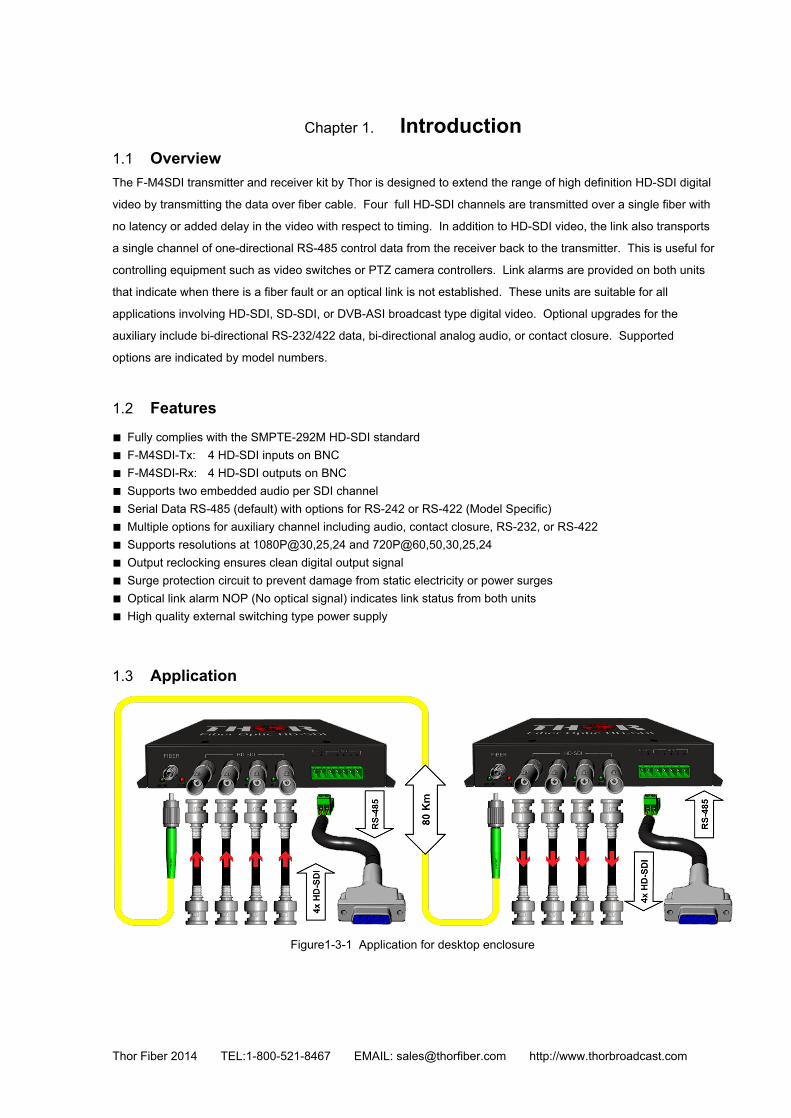
Chapter 1. Introduction 1.1 Overview The FM4SDI transmitter and receiver kit by Thor is designed to extend the range of high definition HDSDI digital
video by transmitting the data over fiber cable. Four full HDSDI channels are transmitted over a single fiber with
no latency or added delay in the video with respect to timing. In addition to HDSDI video, the link also transports
a single channel of onedirectional RS485 control data from the receiver back to the transmitter. This is useful for
controlling equipment such as video switches or PTZ camera controllers. Link alarms are provided on both units
that indicate when there is a fiber fault or an optical link is not established. These units are suitable for all
applications involving HDSDI, SDSDI, or DVBASI broadcast type digital video. Optional upgrades for the
auxiliary include bidirectional RS232/422 data, bidirectional analog audio, or contact closure. Supported
options are indicated by model numbers.
1.2 Features ■ Fully complies with the SMPTE292M HDSDI standard ■ FM4SDITx: 4 HDSDI inputs on BNC ■ FM4SDIRx: 4 HDSDI outputs on BNC ■ Supports two embedded audio per SDI channel ■ Serial Data RS485 (default) with options for RS242 or RS422 (Model Specific) ■ Multiple options for auxiliary channel including audio, contact closure, RS232, or RS422 ■ Supports resolutions at 1080P@30,25,24 and 720P@60,50,30,25,24 ■ Output reclocking ensures clean digital output signal ■ Surge protection circuit to prevent damage from static electricity or power surges ■ Optical link alarm NOP (No optical signal) indicates link status from both units ■ High quality external switching type power supply 1.3 Application
Figure131 Application for desktop enclosure
Thor Fiber 2014 TEL:18005218467 EMAIL: [email protected] http://www.thorbroadcast.com

Chapter 2. RV641N Desktop Equipment 2.1 Front Panel
Figure 211 FM4SDITx Front Panel
Figure 212 FM4SDIRx Front Panel
Table 211 Interfaces Name Description
FIBER (OPT) Optical Fiber Interface, FC Type HDSDI IN Ch 1 4 HDSDI input 14
OUT Ch 1, 4 HDSDI output 14
RS485 RS485 Serial Data, Terminal Block A: RS485 positive terminal B: RS485 negative terminal
AUX
Available Options 2channel bidirectional audio
2channel unidirectional audio
2channel contact closure input/output
1channel bidirectional RS422
2channel bidirectional RS232 channel
Refer to table 213 for more.
Note: if the auxiliary channel is used
as the audio channel, the embedded
audio channel in the HDSDI signal
will be unavailable.
Thor Fiber 2014 TEL:18005218467 EMAIL: [email protected] http://www.thorbroadcast.com

Table 212 Indicators
Name Description
ALARM (NOP) Optical signal loss alarm indicator, red. ON: Optical signal loss is detected at the port. OFF: the optical port receive normal signal.
POWER (RUN) Running indicator LED is green. Blinks when operating normally
OFF: Indicates a problem
IN [1:2] The HDSDI input lock indicator, green. ON: video input normally. OFF: video input abnormally.
OUT[1:2] The SD/ HDSDI output status indicator LED is green. ON: Indicates signal output is normal OFF: Indicates there is no output signal
ACT
RS485 link indicator LED is green. Blinking: Indicates serial data activity OFF: No serial data is being sent or received
Table 213 AUX interface
AUX interface Pin Name Description 2Ch bidirectional audio
FM4SDI2BATx/Rx 1 AOUT1
Audio channel: 1 output
2 AOUT2 Audio channel: 2 output 3 G Ground 4 AIN1 Audio channel: 1 input 5 AIN2 Audio channel: 2 input
2Ch unidirectional audio FM4SDI2ATx
1 AIN1 Audio channel: 1 input
2 AIN2 Audio channel: 2 output 3 G Ground 4 Not Used 5 Not Used
FM4SDI2ARx 1 AOUT1 Audio channel: 1 output 2 AOUT2 Audio channel: 2 output 3 G Ground 4 Not Used 5 Not Used
2ch contact closure output FM4SDI2CCTx
1 NC0 The first channel contact closure output No alarm: the contact is normallyclosed (NC) Alarm: the contact is open
Thor Fiber 2014 TEL:18005218467 EMAIL: [email protected] http://www.thorbroadcast.com

2 COM0 Command contact of the first channel contact closure
3 NC1 The second channel contact closure output
No alarm: the contact is normallyclosed (NC) Alarm: the contact is open
4 COM1 Command contact of the first channel contact closure 5
2ch contact closure input FM4SDI2CCRx
1 K0 The first channel contact closure input
2 COM0 Command contact of the first channel contact closure 3 K1 The second channel contact closure input
4 COM1 Command contact of the second channel contact closure
5 1ch BiDirectional RS232 FM4SDI1S32
1 TXA RS422 differential signal A output
2 TXB RS422 differential signal B output 3 RXA RS422 differential signal A input 4 RXB RS422 differential signal B input 5 G Ground
2ch BiDirectional RS232 FM4SDI2S32
1 TX1 RS232 signal output 1
2 RX1 RS232 signal input 1 3 G Ground 4 TX2 RS232 signal output 2 5 RX2 RS232 signal input 2
Note1: The AUX interface of FM4SDITx and FM4SDIRx are used in pairs, If using a transmitter with an AUX option then the receiver must also have this option for the AUX connection to work properly
1.1 Rear Panel
Figure 221 FM4SDI Rear Panel
Table 221 FM4SDI Rear Panel
Name Description
DC12V DC 12V power input interface Requires the included 12V power supply
Protective ground (PGND) screw
Thor Fiber 2014 TEL:18005218467 EMAIL: [email protected] http://www.thorbroadcast.com

Chapter 2. Technical Specifications Table 41 Technical Specifications
Item Typical value HDSDI Interface
Connector BNC Bit rate 1.485Gb/s
Impedance 75Ω Return loss >15dB Output level 800mVpp±10%
Rise and fall time(HDSDI) ≤270ps HDSDI Alignment jitter (100KHz) ≤0.2UI
HDSDI Timing jitter (10Hz) <1.0UI Standard Comply to SMPTE292M HDSDI standard
Audio Interface (Optional) Connector Terminal Block connector
Impedance Input highimpedance, output 600Ω Quantization grade 24 bits Sample frequency 48KHz
Audio input/output voltage 2VPP Bandwidth 20Hz~20KHz
Total Harmonic Distortion 0.1% RS485 Interface
Connector Terminal Block connector Baud rate 0 ~ 115.2Kb/s
Bit error ratio <109 Duplex Halfduplex
Power and Consumption for desktop Model Power supply DC 12V
DC input voltage range 8V~14V
Power consumption 3W±10%
Environment Requirements
Working temperature 30~60℃
Relative Humidity ≤95%, no condensation
Storage temperature 40~85℃
Equipment dimension Desktop Enclosure Dimensions 180mm x 123mm x 30mm
Thor Fiber 2014 TEL:18005218467 EMAIL: [email protected] http://www.thorbroadcast.com