Embed Size (px)
Citation preview

BN46-00286A-02
User ManualUD22B
The color and the appearance may differ depending on the product, and the specifications are subject to
change without prior notice to improve the performance.

Table Of Contents
BEFORE USING THE PRODUCT
8 Copyright
9 Cleaning9 Storage
10 Safety Precautions10 Symbols11 Electricity and Safety12 Installation 14 Operation
PREPARATIONS 18 Checking the Contents18 Removing the Packaging19 Checking the Components
21 Parts21 External sensor23 Reverse Side25 Remote Control27 Controlling more than one display product using
an external sensor kit
28 Before Installing the Product (Installation Guide)
28 Ventilation30 Dimensions
31 RS232C31 Cable Connection34 Connection36 Control Codes
CONNECTING AND USING A SOURCE DEVICE
45 Before Connecting45 Pre-connection Checkpoints
46 Connecting and Using a PC46 Connecting to a PC48 Changing the Resolution
50 Connecting an External Monitor
Table Of Contents 2

Table Of Contents
51 Connecting to a Video Device51 Connection Using an HDMI-DVI Cable52 Connection Using an HDMI Cable52 Connecting to an Audio System
53 Connecting the network box (Sold separately)
53 MagicInfo
54 Changing the Input source54 Source List
USING MDC 55 Configuring Settings for Multi Control55 ID Setup55 ID Input55 MDC Connection55 Network Setting
56 MDC Program Installation/Uninstallation56 Installation56 Uninstallation
57 What is MDC?57 Connecting to MDC59 Connection Management60 Auto Set ID61 Cloning62 Command Retry63 Getting Started with MDC65 Main Screen Layout66 Menus67 Screen Adjustment71 Sound Adjustment72 System Setup80 Tool Settings82 Other Functions87 Troubleshooting Guide
SCREEN ADJUSTMENT 89 Source List
Table Of Contents 3

Table Of Contents
90 Edit Name
91 Source AutoSwitch Settings
SCREEN ADJUSTMENT 92 Mode92 If the input source is DVI or DP92 If the input source is HDMI
93 Custom93 Contrast93 Brightness93 Sharpness93 Gamma94 Color94 Tint
95 Color Tone95 If the input source is DVI or DisplayPort95 If the input source is HDMI
96 Color Control
96 Color Temp.
97 Size97 If the input source is DVI or DisplayPort98 If the input source is HDMI98 Picture Sizes available by Input Source
99 Digital NR
99 HDMI Black Level
99 Film Mode
99 Dynamic Contrast
100 Lamp Control
100 Picture Reset
SOUND ADJUSTMENT 101 Mode
Table Of Contents 4

Table Of Contents
102 Custom 102 Bass102 Treble102 Balance
103 Auto Volume
103 SRS TS XT
103 Sound Reset
SETUP 104 Language
104 Time104 Clock Set105 Sleep Timer106 Timer1 / Timer2 / Timer3107 Holiday Management
107 Menu Transparency
108 Safety Lock108 Change PIN108 Lock
109 Energy Saving
109 Video Wall109 Video Wall110 Format110 Horizontal111 Vertical111 Screen Position
112 Safety Screen112 Pixel Shift113 Timer114 Bar114 Eraser114 Pixel115 Side Gray
115 Resolution Select
Table Of Contents 5

Table Of Contents
116 Power On Adjustment
116 OSD Rotation
117 Advanced Settings117 Fan & Temperature119 Auto Power119 Button Lock119 User Auto Color120 Standby Control121 Lamp Schedule121 OSD Display122 Software Upgrade
123 Setup Reset
123 Reset All
TROUBLESHOOTING GUIDE
124 Requirements Before Contacting Samsung Customer Service Center
124 Testing the Product124 Checking the Resolution and Frequency124 Check the followings.
127 Q & A
SPECIFICATIONS 128 General
130 PowerSaver
131 Preset Timing Modes
APPENDIX 133 Contact SAMSUNG WORLDWIDE
138 Responsibility for the Pay Service (Cost to Customers)
138 Not a product defect138 A Product damage caused by customer's fault138 Others
Table Of Contents 6

Table Of Contents
139 Optimum Picture Quality and Afterimage Burn-in Prevention
139 Optimum Picture Quality140 Prevention of Afterimage Burn-in
142 Correct Disposal of This Product (Waste Electrical & Electronic Equipment)
142 Correct disposal of batteries in this product
143 Terminology
INDEX
Table Of Contents 7

B
efore Using the ProductCopyright
The contents of this manual are subject to change without notice to improve quality.
2012 Samsung Electronics
Samsung Electronics owns the copyright for this manual.
Use or reproduction of this manual in parts or entirety without the authorization of Samsung Electronics is
prohibited.
The SAMSUNG and SyncMaster logos are registered trademarks of Samsung Electronics.
Microsoft, Windows are registered trademarks of Microsoft Corporation.
VESA, DPM and DDC are registered trademarks of the Video Electronics Standards Association.
Ownership of all other trademarks is attributed to their due owner.
An administration fee may be charged if either
(a) an engineer is called out at your request and there is no defect in the product
(i.e. where you have failed to read this user manual).
(b) you bring the unit to a repair center and there is no defect in the product
(i.e. where you have failed to read this user manual).
The amount of such administration charge will be advised to you before any work or home visit is
carried out.
TruSurround XT, SRS and the symbol are trademarks of SRS Labs, Inc.TruSurround XT technology is incorporated under license form SRS Lab, Inc.
The terms HDMI and HDMI High-Definition Multimedia Interface, and the HDMI Logo are trademarks or registered trademarks of HDMI Licensing LLC in the United States and other countries.
©
8 Before Using the Product

Before Using the Product
Cleaning
Exercise care when cleaning as the panel and exterior of advanced LCDs are easily scratched.
Take the following steps when cleaning.
The following images are for reference only. Real-life situations may differ from what is shown in the
images.
Storage
High-glossy models can develop white stains on the surface if an ultrasonic wave humidifier is used
nearby.
Contact Customer Service Center if the inside of the product needs cleaning (service fee will be
charged).
1. Power off the product and computer.
2. Disconnect the power cord from the product.
Hold the power cable by the plug and do not touch the cable with wet
hands. Otherwise, an electric shock may result.
3. Wipe the product with a clean, soft and dry cloth.
Do not use detergents that contain alcohol, solvent or
surface-active agents.
Do not spray water or detergent directly on the product.
4. Wet a soft and dry cloth in water and wring thoroughly to clean the exterior of the product.
5. Connect the power cord to the product when cleaning is finished.
6. Power on the product and computer.
!
9 Before Using the Product

Before Using the Product
Safety Precautions
Symbols
Caution
RISK OF ELECTRIC SHOCK DO NOT OPEN
Caution : TO REDUCE THE RISK OF ELECTRIC SHOCK, DO NOT REMOVE COVER. (OR BACK)
THERE ARE NO USER SERVICEABLE PARTS INSIDE.
REFER ALL SERVICING TO QUALIFIED PERSONNEL.
This symbol indicates that high voltage is present inside.
It is dangerous to make any kind of contact with any internal part of this product.
This symbol alerts you that important literature concerning operation and maintenance has been included with this product.
Warning A serious or fatal injury may result if instructions are not followed.
Caution Personal injury or damage to properties may result if instructions are not followed.
Activities marked by this symbol are prohibited.
Instructions marked by this symbol must be followed.
10 Before Using the Product

Before Using the Product
Electricity and Safety
The following images are for reference only. Real-life situations may differ from what is shown in the
images.
Warning
Do not use a damaged power cord or plug, or a loose power socket.
An electric shock or fire may result.
Do not use multiple products with a single power socket.
Overheated power sockets may cause a fire.
Do not touch the power plug with wet hands.
Otherwise, an electric shock may result.
Insert the power plug all the way in so it is not loose.
An unsecure connection may cause a fire.
Connect the power plug to a grounded power socket (type 1 insulated devices only).
An electric shock or injury may result.
Do not bend or pull the power cord with force. Be careful not to leave the power cord under a heavy object.
Damage to the cord may result in a fire or electric shock.
Do not place the power cord or product near heat sources.
A fire or electric shock may result.
Clean any dust around the pins of the power plug or the power socket with a dry cloth.
A fire may result.
!
!
!
11 Before Using the Product

Before Using the Product
Caution
Installation
Warning
Do not disconnect the power cord while the product is being used.
The product may become damaged by an electric shock.
Only use the power cord provided with your product by Samsung. Do not use the power cord with other products.
A fire or electric shock may result.
Keep the power socket where the power cord is connected unobstructed.
The power cord must be disconnected to cut off power to the product when an
issue occurs.
Note that the product is not completely powered down by using only the power
button on the remote.
Hold the plug when disconnecting the power cord from the power socket.
An electric shock or fire may result.
DO NOT PLACE CANDLES, INSECT REPELLANTS OR CIGARETTES ON TOP OF THE PRODUCT. DO NOT INSTALL THE PRODUCT NEAR HEAT SOURCES.
A fire may result.
Have a technician install the wall-mount hanger.
Installation by an unqualified person can result in an injury.
Only use approved cabinets.
Do not install the product in poorly ventilated spaces such as a bookcase or closet.
An increased internal temperature may cause a fire.
Install the product at least 10cm away from the wall to allow ventilation.
An increased internal temperature may cause a fire.
!
!
!
!
!
12 Before Using the Product

Before Using the Product
Caution
Keep the plastic packaging out of the reach of children.
Children may suffocate.
Do not install the product on an unstable or vibrating surface (insecure shelf, sloped surface, etc.)
The product may fall and become damaged and/or cause an injury.
Using the product in an area with excess vibration may damage the product or
cause a fire.
Do not install the product in a vehicle or a place exposed to dust, moisture (water drips, etc.), oil, or smoke.
A fire or electric shock may result.
Do not expose the product to direct sunlight, heat, or a hot object such as a stove.
The product lifespan may be reduced or a fire may result.
Do not install the product within the reach of young children.
The product may fall and injure children.
As the front is heavy, install the product on a flat and stable surface.
Edible oil, such as soybean oil, can damage or deform the product. Do not install the product in a kitchen or near a kitchen counter.
Do not drop the product while moving.
Product failure or personal injury may result.
Do not set down the product on its front.
The screen may become damaged.
When installing the product on a cabinet or shelf, make sure that the bottom edge of the front of the product is not protruding.
The product may fall and become damaged and/or cause an injury.
Install the product only on cabinets or shelves of the right size.
!
!
!
13 Before Using the Product

Before Using the Product
Operation
Warning
Set down the product gently
Product failure or personal injury may result.
Installing the product in an unusual place (a place exposed to a lot of fine particles, chemical substances or extreme temperatures, or an airport or train station where the product should operate continuously for an extended period of time) may seriously affect its performance.
Be sure to consult Samsung Customer Service Center if you want to install the
product at such a place.
There is a high voltage inside the product. Never disassemble, repair or modify the product yourself.
A fire or electric shock may result.
Contact Samsung Customer Service Center for repairs.
Before moving the product, turn off the power switch and disconnect the power cable and all other connected cables.
Damage to the cord may result in a fire or electric shock.
If the product generates abnormal sounds, a burning smell or smoke, disconnect the power cord immediately and contact Samsung Customer Service Center.
An electric shock or fire may result.
Do not let children hang from the product or climb on top of it.
Children may become injured or seriously harmed.
If the product is dropped or the outer case is damaged, turn off the power switch and disconnect the power cord. Then contact Samsung Customer Service Center.
Continued use can result in a fire or electric shock.
Do not leave heavy objects or items that children like (toys, sweets, etc.) on top of the product.
The product or heavy objects may fall as children try to reach for the toys or
sweets resulting in a serious injury.
!
SAMSUNG
!
!
!
14 Before Using the Product

Before Using the Product
During a lightning or thunderstorm, power off the product and remove the power cable.
A fire or electric shock may result.
Do not drop objects on the product or apply impact.
A fire or electric shock may result.
Do not move the product by pulling the power cord or any cable.
Product failure, an electric shock or fire may result from a damaged cable.
If a gas leakage is found, do not touch the product or power plug. Also, ventilate the area immediately.
Sparks can cause an explosion or fire.
Do not lift or move the product by pulling the power cord or any cable.
Product failure, an electric shock or fire may result from a damaged cable.
Do not use or keep combustible spray or an inflammable substance near the product.
An explosion or fire may result.
Ensure the vents are not blocked by tablecloths or curtains.
An increased internal temperature may cause a fire.
Do not insert metallic objects (chopsticks, coins, hairpins, etc) or objects that burn easily (paper, matches, etc) into the product (via the vent or input/output ports, etc).
Be sure to power off the product and disconnect the power cord when water or
other foreign substances have entered the product. Then contact Samsung
Customer Service Center.
Product failure, an electric shock or fire may result.
Do not place objects containing liquid (vases, pots, bottles, etc) or metallic objects on top of the product.
Be sure to power off the product and disconnect the power cord when water or
other foreign substances have entered the product. Then contact Samsung
Customer Service Center.
Product failure, an electric shock or fire may result.
!
!
!GAS
!
100
15 Before Using the Product

Before Using the Product
Caution
Leaving the screen fixed on a stationary image for an extended period of time may cause afterimage burn-in or defective pixels.
Activate power-saving mode or a moving-picture screen saver if you will not be
using the product for an extended period of time.
Disconnect the power cord from the power socket if you do not plan on using the product for an extended period of time (vacation, etc).
Dust accumulation combined with heat can cause a fire, electric shock or electric
leakage.
Use the product at the recommended resolution and frequency.
Your eyesight may deteriorate.
Do not hold the product upside-down or move it by holding the stand.
The product may fall and become damaged or cause an injury.
Looking at the screen too close for an extended period of time can deteriorate your eyesight.
Do not use humidifiers or stoves around the product.
A fire or electric shock may result.
Rest your eyes for more than 5 minutes for every 1 hour of product use.
Eye fatigue will be relieved.
Do not touch the screen when the product has been turned on for an extended period of time as it will become hot.
Store small accessories out of the reach of children.
!!
-_-
!
!
!
!
!
16 Before Using the Product
Before Using the Product
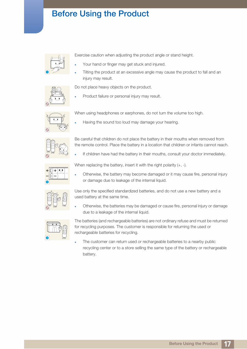
Exercise caution when adjusting the product angle or stand height.
Your hand or finger may get stuck and injured.
Tilting the product at an excessive angle may cause the product to fall and an
injury may result.
Do not place heavy objects on the product.
Product failure or personal injury may result.
When using headphones or earphones, do not turn the volume too high.
Having the sound too loud may damage your hearing.
Be careful that children do not place the battery in their mouths when removed from the remote control. Place the battery in a location that children or infants cannot reach.
If children have had the battery in their mouths, consult your doctor immediately.
When replacing the battery, insert it with the right polarity (+, -).
Otherwise, the battery may become damaged or it may cause fire, personal injury
or damage due to leakage of the internal liquid.
Use only the specified standardized batteries, and do not use a new battery and a used battery at the same time.
Otherwise, the batteries may be damaged or cause fire, personal injury or damage
due to a leakage of the internal liquid.
The batteries (and rechargeable batteries) are not ordinary refuse and must be returned for recycling purposes. The customer is responsible for returning the used or rechargeable batteries for recycling.
The customer can return used or rechargeable batteries to a nearby public
recycling center or to a store selling the same type of the battery or rechargeable
battery.
!
!
!
17 Before Using the Product

1 P
reparations1.1 Checking the Contents
1.1.1 Removing the Packaging
1 Open the packaging box. Be careful not to damage the product when you open the packaging with
a sharp instrument.
2 Remove the styrofoam from the product.
3 Check the product and remove the styrofoam and plastic bag.
The appearance of the actual product may differ from the image shown.
This image is for reference only.
4 Store the box in a dry area so that it can be used when moving the product in the future.
181 Preparations

Preparations1
1.1.2 Checking the ComponentsContact the vendor where you purchased the product if any components are missing.
The appearance of the components and items sold separately may differ from the image shown.
Components
Components may differ in different locations.
Quick setup guideWarranty card
(Not available in some locations)User manual
"MagicInfo Lite" CDBatteries
(Not available in some locations)Remote Control
Power cord External sensor Kit DVI cable
+
+
-
-
191 Preparations

Preparations1
Items sold separatelyThe following items can be purchased at your nearest retailer.
Wall-mount KIT HDMI-DVI cable RS232C Serial cable
HDMI cable DP cable LAN cable
Stereo cable Network box
201 Preparations

Preparations1
1.2 Parts1.2.1 External sensor
The color and shape of parts may differ from what is shown. Specifications are subject to change without notice to improve quality.
Keep the area between the remote sensor and remote control obstacle-free.
Sensor Description
Remote-control sensor
Aim the remote control towards this spot on the LCD Display.
Keep the area between the remote sensor and remote control
obstacle-free.
Brightness sensorAutomatically detects the intensity of ambient light around a selected display and adjusts the screen brightness.
Power indicator Turns off in power-on mode and blinks green in power-saving mode.
[POWER] Use this button for turning the Display on and off.
[SOURCE]Switches from PC mode to Video mode.
Selects the input source that an external device is connected to.
1
2
4
5
3
1
2
3
4
5
211 Preparations

Preparations1
Installing the External sensor221 Preparations

Preparations1
1.2.2 Reverse SideThe color and shape of parts may differ from what is shown. Specifications are subject to change
without notice to improve quality.
Port Description
[DP IN] Connects to a PC using a DP cable.
[HDMI IN (MAGICINFO)]
Connects to a source device using an HDMI cable.
To use MagicInfo, the MagicInfo output of the network box
specified by Samsung must be connected to the [HDMI IN
(MAGICINFO)] port on the product.
For more information on how to purchase and install a network
box, contact Samsung Electronics.
[DVI OUT (LOOPOUT)] Connects to another product using a DVI cable.
[DVI IN] Connects to a source device using a DVI cable or HDMI-DVI cable.
[RS232C OUT] [RS232C IN]Connects to RS232C or MDC through an RS232C Serial cable (cross type)
[RJ45] Connects to RS232C or MDC through an RJ45 cable
[IR OUT]Transmits input signals from an external sensor to another display through IR OUT
[IR / AMBIENT SENSOR IN] Connects to an external sensor
[AUDIO OUT] Connects to the audio of a source device.
AU
DIO
OU
TIR
/ A
MB
IEN
TS
EN
SO
R I
NIR
OU
TR
J45
DP INHDMI IN
(MAGICINFO)DVI OUT
(LOOPOUT) DVI IN RS232C OUT RS232C INPOWER IN
POWER S/W
231 Preparations

Preparations1
Assembling the Holder-Wire stand241 Preparations

Preparations1
1.2.3 Remote ControlUsing other display devices in the same space as the remote control of this product can cause the other display devices to be inadvertently controlled.
Remote control button functions may differ for different products.
Not available.
Return to the previous menu.
Change the input source.
Display or hide the onscreen display
menu, or return to the previous menu.
Not available.
Not available.
Power on the product.
Not available.
MagicInfo Quick Launch Button.
This button is disabled for produacts
that do not support MagicInfo.
MagicInfo can only be enabled
when a network box is connected.
Not available.
Adjust the volume.
Number buttons
Enter the password in the OSD menu.
Power off the product.
Not available.
Mute the sound.
Unmuting the sound: Press MUTE again or
press the volume control(+ VOL -) button.
Not available.
Move to the upper, lower, left or right
menu, or adjust an option's setting.
Confirm a menu selection.
Display information about
the current input source.
Exit the current menu.
Not available.
Not available.
Manually select a connected input source from
DVI, HDMI, or DP.
It sets safe lock function.
Not available.
251 Preparations

Preparations1
Adjusting the OSD with the Remote ControlTo place batteries in the remote control
Store used batteries out of reach of children and recycle.
Do not use a new and used battery together. Replace both batteries at the same time.
Remove batteries when the remote control is not to be used for an extended period of time.
1. Open the OSD menu.
2. Select from Input, Picture, Sound, Setup or Multi Control in the displayed OSD menu screen.
3. Change settings as desired.
4. Finish setting.
5. Close the onscreen display (OSD) menu.
1
3
2
261 Preparations

Preparations1
1.2.4 Controlling more than one display product using an external sensor kitConnect the [IR OUT] port on the product to the [IR / AMBIENT SENSOR IN] port on the other
display product using the dedicated RS232C serial cable.
A command sent from the remote control pointed at product (to which the external sensor kit is
connected) will be received by both display products and .
The appearance may differ depending on the product.
IR O
UT
IR / A
MB
IEN
TS
EN
SO
R IN
IR O
UT
IR / A
MB
IEN
TS
EN
SO
R IN
POWER
SOURCE
1
1 2
271 Preparations

Preparations1
1.3 Before Installing the Product (Installation Guide)To prevent injury, this apparatus must be securely attached to the floor/wall in accordance with the
installation instructions.
Ensure that an authorized installation company installs the wall mount.
Otherwise, it may fall and cause personal injury.
Make sure to install the specified wall mount.
1.3.1 Ventilation
Vertical wall mount condition
(Unit: mm)
For more than 6 rows, auxiliary air conditioning system will be required.
Figure 1.1 Side view
A Distance from the wall (recommended)
B Ambient Temp Measuring Point
It is strongly recommended that ambient
temperature is under 30 C for video-wall
installation.
Considerable amount of heat is added to the
upper units.
Internal temperature of uppermost unit
is 5 ~ 10 C higher than the lowest unit.
(Even there is adequate distance from
the wall)
Configuration 1 x 1 2 x 2 3 x 3 4 x 4 5 x 5
A 40 80 120 160 200
A
B
281 Preparations
Preparations1
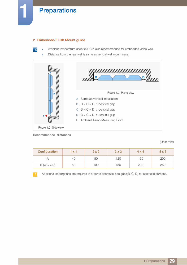
2. Embedded/Flush Mount guideAmbient temperature under 30 C is also recommended for embedded video-wall.
Distance from the rear wall is same as vertical wall mount case.
Recommended distances
(Unit: mm)
Additional cooling fans are required in order to decrease side gaps(B, C, D) for aesthetic purpose.
Figure 1.2 Side view
Figure 1.3 Plane view
A Same as vertical installation
B B = C = D : Identical gap
C B = C = D : Identical gap
D B = C = D : Identical gap
E Ambient Temp Measuring Point
Configuration 1 x 1 2 x 2 3 x 3 4 x 4 5 x 5
A 40 80 120 160 200
B (= C = D) 50 100 150 200 250
B
A
CE
DD
291 Preparations

Preparations1
1.3.2 DimensionsAll drawings are not necessarily to scale. Some dimensions are subject to change without prior notice.
Refer to the dimensions prior to performing installation of your product. Not responsible for
typographical or printed errors.
393.3387.6 81.5
41.5
300.046.6 46.6
301 Preparations

Preparations1
1.4 RS232C1.4.1 Cable Connection
RS232C Cable
Pin assignment
Interface RS232C (9 pins)
Pin TxD (No. 2), RxD (No. 3), GND (No. 5)
Bit rate 9600 bps
Data bits 8 bit
Parity None
Stop bit 1 bit
Flow control None
Maximum length 15m (only shielded type)
Pin Signal
1 Detect data carrier
2 Received data
3 Transmitted data
4 Prepare data terminal
5 Signal ground
6 Prepare data set
7 Send request
8 Clear to send
9 Ring indicator
1 2 3 4 5
6 7 8 9
311 Preparations

Preparations1
RS232C cableConnector: 9-Pin D-Sub
Cable : Cross Cable
LAN Cable
Pin assignment
-P1- -P1- -P2- -P2-
Female Rx
Tx
Gnd
2
3
5
-------->
<--------
---------
3
2
5
Tx
Rx
Gnd
Female
Pin No Standard Color Signal
1 White and orange TX+
2 Orange TX-
3 White and green RX+
4 Blue NC
5 White and blue NC
6 Green RX-
7 White and brown NC
8 Brown NC
1
5
1
59
6
9
6-P1- -P2-
1 2 3 4 5 6 7 8
321 Preparations

Preparations1
Connector : RJ45<Direct LAN cable>
<Cross LAN cable>
Signal P1 P2 Signal
TX+ 1 <--------> 1 TX+
TX- 2 <--------> 2 TX-
RX+ 3 <--------> 3 RX+
RX- 6 <--------> 6 RX-
Signal P1 P2 Signal
TX+ 1 <--------> 3 RX+
TX- 2 <--------> 6 RX-
RX+ 3 <--------> 1 TX+
RX- 6 <--------> 2 TX-
RJ45 MDC RJ45 MDC
HUB
P1
P1P2
P2
PC
RJ45 MDC P1 P2
PC
331 Preparations

Preparations1
1.4.2 ConnectionConnection 1
Connection 2
RS232C IN RS232C OUT RS232C IN RS232C OUT RS232C IN RS232C OUT RS232C IN
RJ45 RJ45
341 Preparations

Preparations1
Connection 3RJ45 RS232C OUT RS232C IN RS232C OUT RS232C IN RS232C OUT RS232C IN
351 Preparations

Preparations1
1.4.3 Control CodesViewing control state (Get control command)
Controlling (Set control command)
Command
Issued IDs can be displayed in hexadecimals. However, ID 0 must be displayed as 0xFF.
All communications take place in hexadecimals. The checksum is calculated by adding up all values
except the header. If a checksum adds up to be more than 2 digits as shown below
(11+FF+01+01=112), the first digit is removed.
E.g. Power On & ID=0
To control all devices connected by a serial cable simultaneously irrespective of IDs, set the ID as
"0xFE" and transmit commands. Commands will be executed by each device but ACK will not
respond.
Header Command
ID
Data length
Checksum0xAA Command type
0
Header Command
ID
Data length Data
Checksum0xAA Command type
1 Value
No. Command type Command Value range
1 Power control 0x11 0~1
2 Volume control 0x12 0~100
3 Input source control 0x14 -
4 Picture Size control 0x15 -
5 Video wall mode control 0x5C 0~1
6 Safety Lock 0x5D 0~1
Header CommandID
Data length Data 1Checksum
0xAA 0x11 1 "Power"
Header CommandID
Data length Data 112
0xAA 0x11 1 1
361 Preparations

Preparations1
Power controlFunction
A product can be powered on and off using a PC.
Viewing power state (Get Power ON / OFF Status)
Setting power ON/Off (Set Power ON / OFF)
"Power": Power code to be set on a product.
1 : Power ON
0 : Power OFF
Ack
"Power": Power code to be set on a product.
Nak
"ERR" : A code showing what error has occurred.
Header CommandID
Data lengthChecksum
0xAA 0x11 0
Header CommandID
Data length DataChecksum
0xAA 0x11 1 "Power"
Header Command ID
Data length Ack/Nak r-CMD Val1Checksum
0xAA 0xFF 3 ‘A’ 0x11 "Power"
Header Command ID
Data length Ack/Nak r-CMD Val1Checksum
0xAA 0xFF 3 ‘N’ 0x11 "ERR"
371 Preparations

Preparations1
Volume controlFunction
The volume of a product can be adjusted using a PC.
Viewing volume state (Get Volume Status)
Setting the volume (Set Volume)
"Volume": Volume value code to be set on a product. (0-100)
Ack
"Volume": Volume value code to be set on a product. (0-100)
Nak
"ERR" : A code showing what error has occurred.
Header CommandID
Data lengthChecksum
0xAA 0x12 0
Header CommandID
Data length DataChecksum
0xAA 0x12 1 "Volume"
Header Command ID
Data length Ack/Nak r-CMD Val1Checksum
0xAA 0xFF 3 ‘A’ 0x12 "Volume"
Header CommandID
Data length Ack/Nak r-CMD Val1Checksum
0xAA 0xFF 3 ‘N’ 0x12 "ERR"
381 Preparations

Preparations1
Input source controlFunction
The input source of a product can be changed using a PC.
Viewing input source state (Get Input Source Status)
Setting the input source (Set Input Source)
"Input Source": An input source code to be set on a product.
DVI_video, HDMI1_PC and HDMI2_PC cannot be used with the Set command. They only respond to "Get" commands.
This model does not support BNC, S-Video, HDMI2 and HDMI2_PC ports.
MagicInfo is only available with models that contain the MagicInfo function.
Ack
Header CommandID
Data lengthChecksum
0xAA 0x14 0
Header Command
ID
Data length Data
Checksum0xAA 0x14 1 "Input Source"
0x14 PC
0x1E BNC
0x18 DVI
0x0C Input source
0x04 S-video
0x08 Component
0x20 MagicInfo
0x1F DVI_video
0x30 RF (TV)
0x40 DTV
0x21 HDMI1
0x22 HDMI1_PC
0x23 HDMI2
0x24 HDMI2_PC
0x25 Display Port
391 Preparations

Preparations1
"Input Source": An input source code to be set on a product.
Nak
"ERR" : A code showing what error has occurred.
Header Command
ID
Data length Ack/Nak r-CMD Val1
Checksum0xAA 0xFF 3 ‘A’ 0x14
"Input Source"
Header CommandID
Data length Ack/Nak r-CMD Val1Checksum
0xAA 0xFF 3 ‘N’ 0x14 "ERR"
401 Preparations

Preparations1
Picture Size ControlFunction
Change Picture Size by Personal Computer.
Can not control picture size when Videowall is On.
Get Picture Size Status
Set Picture Size
"Aspect" : Picture Size Code
Ack
Header CommandID
Data lengthChecksum
0xAA 0x15 0
Header CommandID
Data length Data 1Checksum
0xAA 0xFF 3 "Aspect"
PC1, PC2, DVI, DNC, HDMI_PC
0x10 16 : 9
0x18 4 : 3
AV, S-Video, Component, DVI_Video, HDMI_Video
0x00 Auto Wide
0x01 16 : 9
0x04 Zoom
0x05 Zoom1
0x06 Zoom2
0x31 Wide Zoom
0x0B 4 : 3
0x0C Wide Fit
0x0D Custom
0x0E Smart View 1
0x0F Smart View 2
Common
0x09 Just Scan(Screen Fit)
0x20 Original Ratio
411 Preparations

Preparations1
"Aspect" : Picture Size Code
Nak
"ERR" : A code showing what error has occurred.
Header CommandID
Data length Ack/Nak r-CMD Val1Checksum
0xAA 0xFF 3 ‘N’ 0x15 "Aspect"
Header CommandID
Data length Ack/Nak r-CMD Val1Checksum
0xAA 0xFF 3 ‘N’ 0x15 "ERR"
421 Preparations

Preparations1
Video Wall Mode ControlFunction
Video Wall Mode can be activated on a product using a PC.
This control is only available on a product whose Video Wall is enabled.
This function is not available in MagicInfo.
Viewing video wall mode (Get Video Wall Mode)
Setting the video wall (Set Video Wall Mode)
"Video Wall Mode": A code used to activate Video Wall mode on a product.
1 : Full
0 : Natural
Ack
"Video Wall Mode": A code used to activate Video Wall mode on a product.
Nak
"ERR" : A code showing what error has occurred.
Header CommandID
Data lengthChecksum
0xAA 0x5C 0
Header Command
ID
Data length Data
Checksum0xAA 0x5C 1 "Video Wall Mode"
Header Command
ID
Data length Ack/Nak r-CMD Val1
Checksum0xAA 0xFF 3 ‘A’ 0x5C
"Video Wall Mode"
Header CommandID
Data length Ack/Nak r-CMD Val1Checksum
0xAA 0xFF 3 ‘N’ 0x5C "ERR"
431 Preparations

Preparations1
Safety LockFunction
PC can be used to turn the Safety Lock function on or off on a product.
This control is available regardless of whether or not the power is turned on.
Viewing the safety lock state (Get Safety Lock Status)
Enabling or disabling safety lock (Set Safety Lock Enable / Disable)
"Safety Lock": Safety lock code to be set on a product.
1 : ON
0 : OFF
Ack
"Safety Lock": Safety lock code to be set on a product.
Nak
"ERR" : A code showing what error has occurred.
Header CommandID
Data lengthChecksum
0xAA 0x5D 0
Header Command
ID
Data length Data
Checksum0xAA 0x5D 1 "Safety Lock"
Header Command
ID
Data length Ack/Nak r-CMD Val1
Checksum0xAA 0xFF 3 ‘A’ 0x5D
"Safety Lock"
Header CommandID
Data length Ack/Nak r-CMD Val1Checksum
0xAA 0xFF 3 ‘N’ 0x5D "ERR"
441 Preparations

2 C
onnecting and Using a Source Device2.1 Before Connecting
Check the following before you connect this product with other devices. Devices that can be connected
to this product include PCs, camcorders, speakers, set top boxes and DVD/Blu-ray Disc players.
2.1.1 Pre-connection Checkpoints
Before connecting a source device, read the user manual provided with it. The number and locations
of ports on source devices may differ from device to device.
Do not connect the power cable until all connections are completed. Connecting the power cable
during connection may damage the product.
Connect the sound ports correctly: left = white and right = red.
Check the types of ports at the back of the product you want to connect.
Audio
452 Connecting and Using a Source Device

Connecting and Using a Source Device2
2.2 Connecting and Using a PC2.2.1 Connecting to a PC
Do not connect the power cable before connecting all other cables.
Ensure you connect a source device first before connecting the power cable.
A PC can be connected to the product in a variety of ways.
Select a connection method suitable for your PC.
Connecting parts may differ in different products.
The following images are for reference only. Real-life situations may differ from what is shown in the images.
Connection using a DVI cable (Digital type)
Connection Using an HDMI-DVI Cable
When you connect a PC to the product using an HDMI-DVI cable, set Edit Name to DVI PC to access
video and audio content stored on the PC.
DVI IN
HDMI IN(MAGICINFO)
462 Connecting and Using a Source Device

Connecting and Using a Source Device2
Connection Using an HDMI CableConnection Using an DP Cable
HDMI IN(MAGICINFO)
DP IN
472 Connecting and Using a Source Device

Connecting and Using a Source Device2
2.2.2 Changing the ResolutionAdjust the resolution and refresh rate in Control Panel on your PC to obtain optimum picture quality.
The picture quality of TFT-LCDs may degrade if the optimum resolution is not selected.
Changing the Resolution on Windows XP
Go to Control Panel Display Settings, and change the resolution.
Changing the Resolution on Windows Vista
Go to Control Panel Personal Settings Display Settings, and change the resolution.
1 2 3
**** ****
**********
1 2
3 4
**********************
482 Connecting and Using a Source Device

Connecting and Using a Source Device2
Changing the Resolution on Windows 7Go to Control Panel Display Screen Resolution, and change the resolution.
1 2
3 4
**** ****
492 Connecting and Using a Source Device

Connecting and Using a Source Device2
2.3 Connecting an External MonitorThe following images are for reference only. Real-life situations may differ from what is shown in the images.
The Loopout function can be used to duplicate the screen of the primary display. Connect [DVI OUT] on the primary display to [DVI IN] or [HDMI IN] on another display.
Up to Full HD resolution can be supported. Compatible input sources include DVI IN, DP IN and HDMI IN. Multiple monitors that are daisy-chained have a limit to the connectable monitors.
The [DVI OUT] port on this product does not support the HDCP input.
DVI OUT
502 Connecting and Using a Source Device

Connecting and Using a Source Device2
2.4 Connecting to a Video DeviceDo not connect the power cable before connecting all other cables.
Ensure you connect a source device first before connecting the power cable.
You can connect a video device to the product using a cable.
The following images are for reference only. Real-life situations may differ from what is shown in the images.
Connecting parts may differ in different products.
Press the SOURCE button on the remote control to change the source.
2.4.1 Connection Using an HDMI-DVI Cable
Audio will not be enabled if the product is connected to a video device using an HDMI-DVI cable. To resolve this, additionally connect an audio cable to the audio ports on the product and video device.
Supported resolutions include 1080p (50/60Hz), 720p (50/60Hz), 480p, and 576p.
HDMI IN(MAGICINFO)
512 Connecting and Using a Source Device

Connecting and Using a Source Device2
2.4.2 Connection Using an HDMI CableUsing an HDMI cable or HDMI to DVI Cable (up to 1080p)
For better picture and audio quality, connect to a digital device using an HDMI cable.
An HDMI cable supports digital video and audio signals, and does not require an audio cable.
To connect the product to a digital device that does not support HDMI output, use an HDMI/
DVI and audio cables.
The picture may not display normally (if at all) or the audio may not work if an external device that
uses an older version of HDMI mode is connected to the product. If such a problem occurs, ask the
manufacturer of the external device about the HDMI version and, if out of date, request an upgrade.
Be sure to use an HDMI cable with a thickness of 14 mm or less.
Be sure to purchase a certified HDMI cable. Otherwise, the picture may not display or a connection
error may occur.
A basic high-speed HDMI cable or one with ethernet is recommended. This product does not
support the ethernet function via HDMI.
2.4.3 Connecting to an Audio System
HDMI IN(MAGICINFO)
AUDIO OUT
522 Connecting and Using a Source Device

Connecting and Using a Source Device2
2.5 Connecting the network box (Sold separately)For details on how to connect to a network box, refer to the user's manual provided with the network
box upon purchase.
2.5.1 MagicInfo
To use MagicInfo, a network box (sold separately) must be connected to the product.
To change the MagicInfo settings, run "MagicinfoSetupWizard" on the desktop.
For details on how to use MagicInfo, refer to the DVD provided with the network box.
The information in this section is subject to change without notice for quality improvement.
If a problem occurs after installing an operating system other than the one provided with the network box, restoring the previous version of the operating system, or installing software that is not compatible with the operating system provided, you will not be able to benefit from technical support and will be charged a fee for a visit from a service technician. A product exchange or refund will also not be available.
HDMI IN(MAGICINFO)
532 Connecting and Using a Source Device

Connecting and Using a Source Device2
2.6 Changing the Input source2.6.1 Source List
MENU Input Source List ENTER
You can display the screen of a source device connected to the product. Select a source from source list
to display the screen of the selected source.
Refer to page 89 for details about the Input menu.
DVI
HDMI
DisplayPort
MagicInfo - Activated when a network box is connected.
The input source can also be changed by using the SOURCE button on the remote control.
The screen may not display correctly if an incorrect source is selected for the source device you want to
convert to.
O m
542 Connecting and Using a Source Device
3 UMD
sing MDCC (Multiple Display Control) is an application that allows you to easily control multiple display
devices simultaneously using a PC.
3.1 Configuring Settings for Multi Control
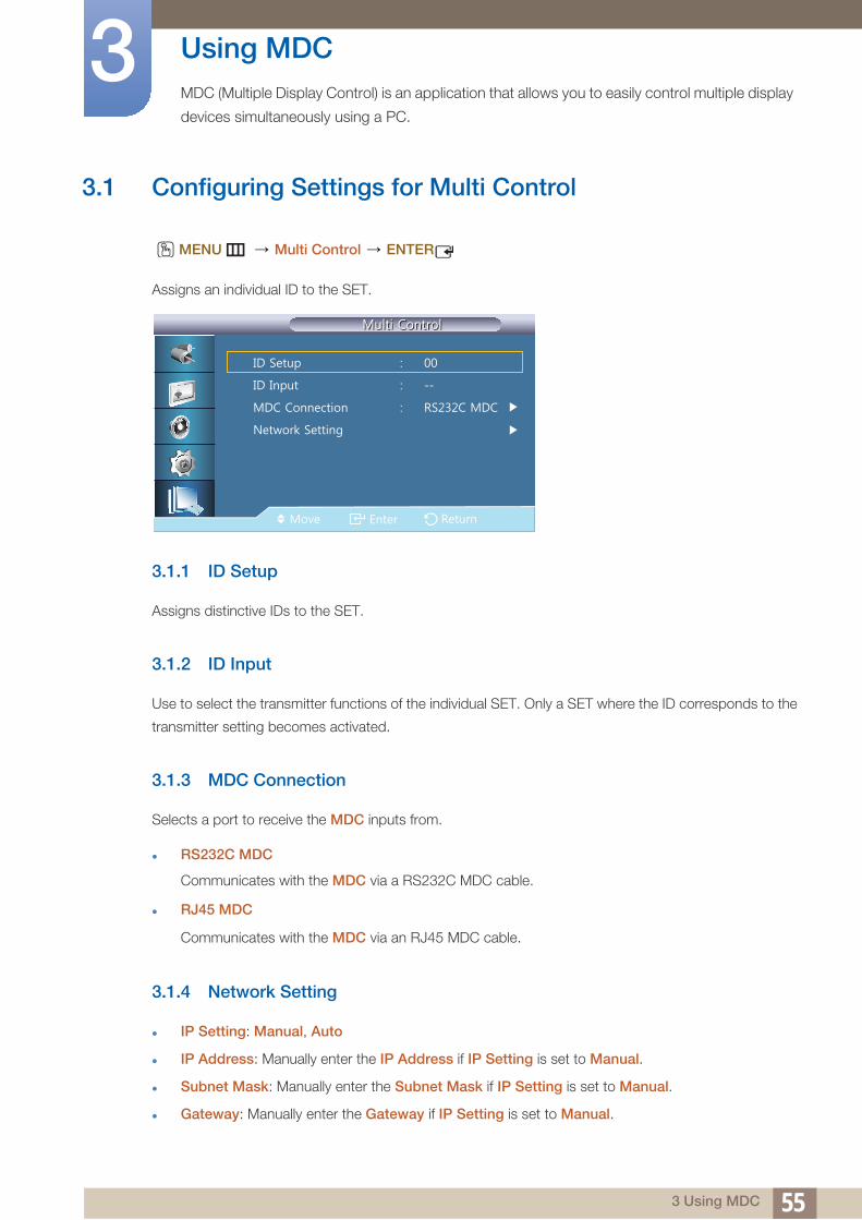
MENU Multi Control ENTER
Assigns an individual ID to the SET.
3.1.1 ID Setup
Assigns distinctive IDs to the SET.
3.1.2 ID Input
Use to select the transmitter functions of the individual SET. Only a SET where the ID corresponds to the
transmitter setting becomes activated.
3.1.3 MDC Connection
Selects a port to receive the MDC inputs from.
RS232C MDC
Communicates with the MDC via a RS232C MDC cable.
RJ45 MDC
Communicates with the MDC via an RJ45 MDC cable.
3.1.4 Network Setting
IP Setting: Manual, Auto
IP Address: Manually enter the IP Address if IP Setting is set to Manual.
Subnet Mask: Manually enter the Subnet Mask if IP Setting is set to Manual.
Gateway: Manually enter the Gateway if IP Setting is set to Manual.
O m
553 Using MDC

Using MDC3
3.2 MDC Program Installation/Uninstallation3.2.1 Installation
1 Insert the installation CD into the CD-ROM drive.
2 Click the MDC Unified installation program.
If a software installation window is not displayed on the main screen, install with the "MDC Unified"
execution file in the MDC folder on the CD.
3 Select a language for installation. Next, click "OK".
4 When the "Welcome to the InstallShield Wizard for MDC_Unified" screen appears, click "Next".
5 In the "License Agreement" window displayed, select "I accept the terms in the license agreement"
and click "Next".
6 In the displayed "Customer Information" window, fill out all the information fields and click "Next".
7 In the displayed "Destination Folder" window, select the directory path you want to install the
program in and click "Next".
If the directory path is not specified, the program will be installed in the default directory path.
8 In the displayed "Ready to Install the Program" window, check the directory path to install the
program in and click "Install".
9 Installation progress will be displayed.
10 Click "Finish" in the displayed "InstallShield Wizard Complete" window.
Select "Launch MDC Unified" and click "Finish" to run the MDC program immediately.
11 The MDC Unified shortcut icon will be created on the desktop after installation.
The MDC execution icon may not be displayed depending on the PC system or product specifications.
Press F5 if the execution icon is not displayed.
3.2.2 Uninstallation
1 Select Settings > Control Panel on the Start menu and double-click Add/Delete Program.
2 Select MDC Unified from the list and click Change/Remove.
MDC installation can be affected by the graphics card, mother board and network conditions.
563 Using MDC

Using MDC3
3.3 What is MDC?Multiple display control (MDC) is an application that allows you to easily control multiple display devices
simultaneously using a PC.
3.3.1 Connecting to MDC
Using MDC via RS-232C (serial data communications standards)
An RS-232C serial cable must be connected to the serial ports on the PC and monitor.
RS232C OUT
RS232C IN
573 Using MDC

Using MDC3
Using MDC via EthernetEnter the IP for the primary display device and connect the device to the PC. One display device can
connect to another using an RS-232C serial cable.
Communicate with LAN cable
Multiple products can be connected using the [RJ45] port on the product and the LAN ports on the
HUB.
Communicate with RS232C Serial cable via the LAN cable
Multiple products can be connected using the [RS232C OUT] port on the product.
RJ45
RS232C OUT
RJ45
583 Using MDC

Using MDC3
3.3.2 Connection ManagementConnection management includes the Connection list and Connection list modification options.
Connection list – Connection list shows the details of the connections such as connection setting (IP/
COM, Port No, MAC, and Connection Type), connection status, Set ID Range, and detected devices.
Each connection can contain a maximum of 100 devices connected in serial daisy-chain fashion. All the
LFDs detected in a connection are displayed in the Device list, where the user can make groups and
send commands to detected devices.
Connection list modification options – Connection modification options includes Add, Edit, Delete,
and Refresh.
593 Using MDC

Using MDC3
3.3.3 Auto Set IDAuto Set ID feature assigns a Set ID for all the LFDs connected in daisy-chain of a selected connection.
There can be a maximum of 100 LFDs in a connection. The Set ID is assigned sequentially in the daisy-
chain running from 1 to 99, and then finally to Set ID 0.
603 Using MDC

Using MDC3
3.3.4 CloningUsing the Cloning feature, you can copy the setting of one LFD and apply it to multiple selected LFDs.
You can select specific tab categories or all tab categories for cloning, using the copy setting option
window.
613 Using MDC

Using MDC3
3.3.5 Command RetryThis feature is used to specify the maximum number of times the MDC command will be retried in case of
there being no reply or a corrupted reply from an LFD. The retry count value can be set using the MDC
options window. The retry count value must be between 1-10. The default value is 1.
623 Using MDC
Using MDC3
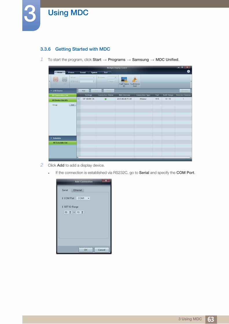
3.3.6 Getting Started with MDC1 To start the program, click Start Programs Samsung MDC Unified.
2 Click Add to add a display device.
If the connection is established via RS232C, go to Serial and specify the COM Port.
633 Using MDC

Using MDC3
If the connection is established via Ethernet, enter the IP that was entered for the displaydevice.
643 Using MDC

Using MDC3
3.3.7 Main Screen LayoutMenu Bar Change the status of a display device or the properties of the program.
Device Category View a list of connected display devices or device groups.
Schedule Category View a list of schedules for display devices.
Set List Select the display device you want to adjust.
Modify the Set List Add, edit, regroup or delete sets.
Help Topics Display help topics for the program.
4
3
2
1 6
5
1
2
3
4
5
6
653 Using MDC

Using MDC3
3.3.8 MenusYou can power on or off a selected device or change the input source or volume of the device.
Choose display devices from the list of sets, and select the Home tab.
Home
Select an item and change the corresponding setting.
Power
On: Power on a selected display.
Off: Power off a selected dis
Input
Input Source : Change the input source.
Input sources available can vary depending on the Display Device Models.
The input source can be changed only for displays that are turned on.
Channel : Change the channel.
The TV channel can be changed by using the up/down arrow keys.
The channel can be changed only when the input source is TV.
Only registered channels can be selected.
Volume
The volume can be changed or the sound can be muted only for displays that are turned on.
Volume
The volume can be adjusted using the slider bar in the range of 0 to 100.
Adjust the volume of a selected display.
Input
Enable or disable Mute for a selected display.
Mute will automatically be disabled if Volume is adjusted when Mute is on.
1
2
663 Using MDC

Using MDC3
AlertFault Device
This menu shows a list of display devices which have following errors - fan error, temperature
error, brightness sensor error, or lamp error.
Select a display device from the list. The Repair button will be enabled. Click the refresh button
to refresh the error status of the display device. The recovered display device will disappear
from the Fault Device List.
Fault Device Alert
Display device in which error is detected will be reported by email.
Fill in all required fields. The Test and OK buttons will be enabled. Ensure the Sender
information and at least one Recipient are entered.
3.3.9 Screen Adjustment
The screen settings (contrast, brightness, etc.) can be adjusted.
Choose display devices from the list of sets, and select the Picture tab.
Custom
Select an item and change the corresponding screen setting.
Color and Tint are not available if the input source is PC.
Red, Green, Blue and PC Screen Adjustment are not available if the input source is Video.
Color, Tint, Color Tone, Color Temp, Red, Green, Blue and PC Screen Adjustment are not available if both PC Source and Video Source are selected.
Contrast
Adjust the contrast for the selected display device.
Brightness
Adjust the brightness for the selected display device.
Color
Adjust the colors for the selected display device.
Tint (G/R)
Adjust the tint for the selected display device.
3
673 Using MDC

Using MDC3
Color ToneAdjust the background color tone for the selected display device.
Color Temp
Adjust the color temperature for the selected display device.
This option is enabled if Color Tone is set to Off.
Red
Customize the intensity of red color for the selected display device.
Green
Customize the intensity of green color for the selected display device.
Blue
Customize the intensity of blue color for the selected display device.
683 Using MDC

Using MDC3
OptionsDynamic Contrast
Adjust the Dynamic Contrast for the selected display device.
Gamma Control
Change the gamma value for the selected display.
Auto Motion Plus
This option is used to view dynamic images.
Off: Disable the Auto Motion Plus function.
Clear: Set the level of Auto Motion Plus to clear. This mode is suitable to display vivid images.
Standard: Set the level of Auto Motion Plus to standard.
Smooth: Set the level of Auto Motion Plus to smooth. This mode is suitable to display smooth
images.
Custom: Customize the level of screen burn-in or flickering.
Demo: This function demonstrates the technology of Auto Motion Plus. The result when the mode
is changed can be previewed on the left side of the window.
Auto Motion Plus may not be available depending on the product.
Brightness Sensor
Enable or disable the Brightness Sensor for the selected display device.
The Brightness Sensor detects the ambient light intensity and automatically adjusts the screen
brightness.
Brightness Sensor may not be available depending on the product.
693 Using MDC

Using MDC3
SizePicture Size
Adjust the screen size for the selected display device.
The Detail item will be disabled if Picture Size is set to a mode that does not support detailed
configuration.
The -/+ buttons can be used to adjust Zoom.
The screen can be relocated using the up/down/left/right buttons.
Detail
You can view details of the selected screen size.
PC Screen Adjustment
Frequency adjustment or fine-tuning is available by using the -/+ buttons in Coarse or Fine.
To relocate the screen, click one of the four images below Position.
To automatically adjust the frequency, fine-tune or relocate the screen, click Auto Adjustment.
703 Using MDC

Using MDC3
3.3.10 Sound AdjustmentYou can change the sound settings.
Choose display devices from the list of sets, and select the Sound tab.
The Bass or Treble item will be disabled if the item is not supported by the selected set.
Bass
Adjust the bass for the selected display.
Treble
Adjust the treble for the selected display.
Balance (L/R)
Adjust the volume of the left and right speakers of the selected display device.
SRS TS XT
Enable or disable the SRS TS XT effect for the selected display device.
713 Using MDC

Using MDC3
3.3.11 System SetupChoose display devices from the list of sets, and select the System tab.
Video Wall
The Video Wall function can be used to display part of a whole picture or repeat the same picture on
each of connected multiple display devices.
Video Wall is enabled only when devices are in the group.
Video Wall
Enable or disable Video Wall.
Format
Select the format to display the split screen.
Full Natural
723 Using MDC

Using MDC3
HSelect the number of horizontal display devices.
A maximum of 15 displays can be arranged in a row.
A maximum of 6 can be assigned to V if 15 is assigned to H.
V
Select the number of vertical display devices.
A maximum of 15 displays can be arranged in a row.
A maximum of 6 can be assigned to V if 15 is assigned to H.
Screen Position
View the layout of displays (configured by the screen divider) or change the layout as required.
Screen Position and Preview are enabled when Video Wall is set to on.
Note that if multiple sets are selected, Preview is enabled only if the settings for H and V match the
layout of the selected sets.
To change the Position, select a set and drag it to a new position.
The range of screen divider settings may differ depending on the model.
733 Using MDC

Using MDC3
PIPBasic information required to adjust PIP will appear in the menu screen.
PIP will be disabled when Video Wall is ON.
Note that Picture Size is disabled when PIP is ON.
PIP Size
View the PIP Size of the current display.
PIP Source
Select a PIP input source.
Sound Select
Select and enable the sound from either the primary screen or secondary screen.
Channel
The channel can be changed if PIP Source is TV.
743 Using MDC

Using MDC3
GeneralUser Auto Color
Automatically adjust the screen colors.
Auto Power
Set the product to automatically power on.
Standby Control
Set the standby mode to activate if an input source is not detected.
Fan & Temperature
Configure the settings required to detect the fan speed and internal temperature for the product's
protection.
Fan Control
Select a method to configure the fan speed.
Fan Speed
Configure the fan speed.
Temperature
Detect the internal temperature by specifying the range of temperature.
753 Using MDC

Using MDC3
SecuritySafety Lock
Lock the on-screen menus.
To unlock the menus, set Safety Lock to Off.
Button Lock
Lock the buttons on the display device.
To unlock the buttons, set Button Lock to Off.
OSD Display
Source OSD
Select whether to display a message when the Source is changed.
Not Optimum Mode OSD
Select whether to display a message when a non-compatible mode is selected.
No Signal OSD
Select whether to display a message when there is no input signal.
MDC OSD
Select whether to display a message when settings are changed by the MDC.
763 Using MDC

Using MDC3
TimeClock Set
Change the current time on the selected display device according to the time set on a PC.
If the time is not set on the display device, null values will be displayed.
Timer
On Time: Set the time to power on the selected display device.
Off Time: Set the time to power off the selected display device.
Volume: Specify the volume of the display device when it is powered on by On Time.
Source: Specify the input source of the display device when it is powered on by On Time.
Holiday: The Holiday Management settings can be applied to the Timer.
Repeat : Specify the period for which you want to repeat the selected Timer.
773 Using MDC

Using MDC3
Once: Activate the timer only one time.EveryDay: Activate the timer every day.
Mon~Fri: Activate the timer from Monday through Friday.
Mon~Sat: Activate the timer from Monday through Saturday.
Sat~Sun: Activate the timer on Saturdays and Sundays.
Manual: Customize days of the week.
The checkboxes to select days of the week below Repeat are enabled only if Manual is selected.
Holiday Management
Holiday Management allows you to prevent devices that are set to be powered on by the Timer from
turning on at a specified date.
The Holiday Management function can be enabled or disabled in the Timer settings menu.
Add: You can specify holidays:
Click the Add button in the Holiday Management window.
Delete: Delete holidays. check the corresponding checkboxes and click this button.
List of holidays: View a list of holidays you have added.
783 Using MDC

Using MDC3
Screen Burn ProtectionPixel Shift
Move the screen slightly at specified time intervals to prevent screen burn-in.
Screen Saver
This function prevents screen burn-in when the screen of the selected display device is left idle for an
extended period of time.
Interval: Set the interval to activate the Screen Saver.
Mode: The Time setting can vary for each Mode.
Safety Screen
793 Using MDC

Using MDC3
The Safety Screen function can be used to prevent screen burn-in when a stationary image displays onthe screen of a display device for an extended period of time.
Lamp Control
Lamp Control is used to adjust the backlight to reduce power consumption.
Automatically adjust the backlight of the selected display device at a specified time.
If Manual Lamp Control is adjusted, Auto Lamp Control will automatically switch to Off.
Manually adjust the backlight for the selected display.
If Auto Lamp Control is adjusted, Manual Lamp Control will automatically switch to Off.
Ambient Light: Ambient Light detects ambient light intensity and automatically adjusts the screen
brightness of all the LFDs in the same serial chain.
3.3.12 Tool Settings
Security
Panel Control
Turn on or off the screen of a display device.
Remote Control
Enable or disable the remote control.
1 2 3 4
1
803 Using MDC

Using MDC3
ResetReset Picture
Reset the screen settings.
Reset Sound
Reset the sound settings.
Reset System
Reset the system settings.
Reset All
Reset the screen, sound and system settings at the same time.
Edit Column
Select the items you want to display in the list of sets.
Information
View the program information.
2
3
4
813 Using MDC

Using MDC3
3.3.13 Other FunctionsResizing a Window
Place the mouse pointer on a corner of the program window. An arrow will appear. Move the arrow to
customize the size of the program window.
823 Using MDC

Using MDC3
Group ManagementCreating Groups
Create groups and manage the list of sets on a group basis.
Duplicate group names cannot be used.
1 Right-click and select Group>Edit in the display device list section on the left side of the program
window.
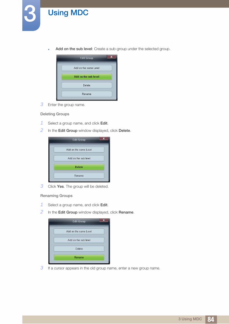
2 In the Edit Group window displayed, click Add on the sub level or Add on the same level.
Add on the same level: Create a group on the same level as the selected group.
The Add on the same level button is enabled only if at least one group is created.
833 Using MDC
Using MDC3
Add on the sub level: Create a sub-group under the selected group.3 Enter the group name.
Deleting Groups
1 Select a group name, and click Edit.
2 In the Edit Group window displayed, click Delete.
3 Click Yes. The group will be deleted.
Renaming Groups
1 Select a group name, and click Edit.
2 In the Edit Group window displayed, click Rename.
3 If a cursor appears in the old group name, enter a new group name.
Rename
843 Using MDC

Using MDC3
Schedule ManagementCreating Schedules
Create and register a schedule on a group basis.
1 Click All Schedule List in the schedule section on the left side of the program window. The Add
button will be enabled in the middle.
2 Click the Add button. The Add Schedule window will appear.
853 Using MDC

Using MDC3
3 Click Add below the Device Group item, and select the group you want to add a schedule to.4 Select Date&Time/Action and click OK. The schedule will be added and a list of schedules will
appear in the set list window.
Device Group: Select a group.
Date&Time
Instant Execution: Run the schedule immediately.
Timer Set the date, time and interval to run the schedule.
Action: Select a function that will activate at the specified time and interval.
Schedule Modification
To modify a schedule, select the schedule and click Edit.
Deleting a Schedule
To delete a schedule, select the schedule and click Delete.
863 Using MDC

Using MDC3
3.3.14 Troubleshooting GuideThis program may malfunction sometimes due to a communication problem between the PC and
display or electromagnetic waves emitted from nearby electronic devices.
Issue Solution
The display you want to control does not appear on the system information chart.
1. Check the connection of the RS232C cable (check that the cable is properly connected to appropriate serial port).
2. Check that another display with a duplicate ID is not connected. Connecting displays with a duplicate ID can cause the displays not to be shown due to data collision.
3. Check that the display ID is within the range of 0 and 99. (Change the ID using the Display menu.)
For a display that supports the ID in a range of 0 to 99,
the ID should be set between 0 and 99.
The display you want to control does not appear on the other Control Info Grids.
Check that the display is powered on. (See the power status in the system information chart.)
Ensure you select the input source the display is connected to.
The following message appears repeatedly.
Check that the display you want to control is selected.
Displays power on or off at different time from one another even though On Time or Off Time is set.
Adjust the time on the PC to synchronize the time between the connected displays.
The remote control does not work. The remote control may not work if the RS-232C cable is removed or the program is closed abnormally while the Remote Control function is Disable. To resolve this, run the program again and set Remote Control to Enable.
873 Using MDC

Using MDC3
How display properties are shown when multiple displays are used1 When no display is selected: The default value is displayed.
2 When one display is selected: Settings for the selected display are displayed.
3 When two displays are selected (e.g. in sequence of ID 1 andID 3): The settings for ID 1 are
displayed before the settings for ID 3.
4 When the All+Select checkbox is checked and all displays are selected: The default settings are
displayed.
883 Using MDC

4 S
creen Adjustment4.1 Source List
MENU Input Source List ENTER
You can display the screen of a source device connected to the product. Select a source from source list
to display the screen of the selected source.
DVI
HDMI
DisplayPort
MagicInfo - Activated when a network box is connected.
The input source can also be changed by using the SOURCE button on the remote control.
The screen may not display correctly if an incorrect source is selected for the source device you want to
convert to.
O m
894 Screen Adjustment

Screen Adjustment4
4.2 Edit NameMENU Input Edit Name ENTER
You can rename a connected source device.
Sometimes the screen will not display properly unless the name of a source device is specified in
Edit Name. In addition, it is best to rename the source device in Edit Name to obtain optimal picture
quality.
The list can include the following source devices. Source devices on the list differ depending on the
selected source.
VCR / DVD / Cable STB / HD STB / Satellite STB / AV Receiver / DVD Receiver / Game / Camcorder / DVD Combo / DHR / PC / DVI PC / DVI Devices
Available settings in the Picture menu depend on the current source and settings made in Edit Name.
When connecting a PC to the [HDMI IN (MAGICINFO)] port with HDMI cable, you should set the
product to PC mode under Edit Name.
When connecting a PC to the [HDMI IN (MAGICINFO)] port with HDMI to DVI cable, you should set
the product to DVI PC mode under Edit Name.
When connecting an AV devices to the [HDMI IN (MAGICINFO)] port with HDMI to DVI cable, you
should set the product to DVI Devices mode under Edit Name.
O m
�
�
�
904 Screen Adjustment

Screen Adjustment4
4.3 Source AutoSwitch SettingsMENU Input Source AutoSwitch Settings ENTER
You can rename a connected source device.
Turning on the display with Source AutoSwitch On, and the previous video source selection is not
active, the display will automatically search the different video input sources for active video.
Source AutoSwitch
When the Source AutoSwitch is On, the display video source will automatically be searched for
active video.
The Primary Source selection will be activated, if the current video source is not recognized.
Secondary Source selection will become active, if no primary video source is available.
If both the primary and secondary input sources are not recognized, the display will perform two
searches for an active source, each search checking the primary and then secondary source. If both
searches fail, the display will return to the first video source and display a message indicating that
there is no signal.
When the Primary Source selection is set to All, the display will search all the video source inputs
twice in sequence looking for an active video source, returning back to the first video source in the
sequence if no video is found.
Press / to select the option you want and press [ ].
Primary Source
Specify Primary Source for the automatic input source.
Secondary Source
Specify Secondary Source for the automatic input source.
O m
�
�
�
914 Screen Adjustment

5 SCo
creen Adjustmentnfigure the Picture settings (Brightness, Colo(u)r Tone, etc.).
The layout of the Picture menu options may vary depending on the product.
5.1 Mode
MENU Picture Mode ENTER
Select a picture mode (Mode) suitable for the environment where the product will be used. Different
Mode options are displayed depending on the current input source.
5.1.1 If the input source is DVI or DP
Information: This mode reduces eye fatigue and is suitable for displaying information to the public.
Advertisement: This mode is suitable for displaying video content and indoor/outdoor
advertisements.
Custom: Customize the screen settings as desired.
5.1.2 If the input source is HDMI
Dynamic: This mode is suitable when the ambient light is bright.
Standard: This mode is generally suitable for any environment.
Movie: This mode reduces eye fatigue.
Custom: Customize the screen settings as desired.
O m
925 Screen Adjustment

Screen Adjustment5
5.2 CustomMENU Picture Custom ENTER
By using the on-screen menus, the contrast and brightness can be changed to your personal preference.
Not available when Dynamic Contrast is set to On.
5.2.1 Contrast
Adjusts the Contrast.
5.2.2 Brightness
Adjusts the Brightness.
5.2.3 Sharpness
Adjusts the Sharpness.
5.2.4 Gamma
Adjust the mid-range brightness (Gamma) for the picture.
Natural
Mode1: Sets the picture brighter than Natural.
Mode2: Sets the picture darker than Mode1.
Mode3: Increases the contrast between dark and bright colors.
Enabled only in DVI, DisplayPort mode.
O m
935 Screen Adjustment

Screen Adjustment5
5.2.5 ColorAdjusts the picture Color.
Available only in HDMI mode.
5.2.6 Tint
Adds a natural tone to the display.
Available only in HDMI mode.
945 Screen Adjustment

Screen Adjustment5
5.3 Color ToneMENU Picture Color Tone ENTER
The color tones can be changed. The individual Color components are also user adjustable.
Not available when Dynamic Contrast is set to On.
5.3.1 If the input source is DVI or DisplayPort
If you set the Color Tone to Cool, Normal, Warm, or Custom, the Color Temp. function is disabled.
If you set the Color Tone to Off, the Color Control function is disabled.
5.3.2 If the input source is HDMI
If you set the Color Tone to Cool2, Cool1, Normal, Warm1, or Warm2, the Color Temp. function is
disabled.
O m
9 5
5 Screen Adjustment

Screen Adjustment5
5.4 Color ControlMENU Picture Color Control ENTER
Adjusts individual Red, Green, Blue color balance.
Not available when Dynamic Contrast is set to On.
5.5 Color Temp.
MENU Picture Color Temp. ENTER
Adjust the color temperature (Red/Green/Blue). (Range: 3000K–15000K)
Not available when Dynamic Contrast is set to On.
O m
O m
965 Screen Adjustment

Screen Adjustment5
5.6 SizeMENU Picture Size ENTER
The Size can be switched.
5.6.1 If the input source is DVI or DisplayPort
16:9: Sets the picture to 16:9 wide mode.
4:3: Sets the picture to basic (4:3) mode.
Do not set your product to 4:3 format for a long time. The borders displayed on the left and right,
or top and bottom of the screen may cause image retention (screen burn) which is not covered by
the warranty.
Original Ratio: Display the image with its original aspect ratio.
Available ports may differ depending on the model.(page 21)
Screen Fit: Display images in the original aspect ratio.
O m
975 Screen Adjustment

Screen Adjustment5
5.6.2 If the input source is HDMI16:9: Sets the picture to 16:9 wide mode.
Zoom1: Use for moderate magnification. Cuts off the top and sides.
Zoom2: Use for a stronger magnification.
4:3: Sets the picture to basic (4:3) mode.
Do not set your product to 4:3 format for a long time. The borders displayed on the left and right,
or top and bottom of the screen may cause image retention(screen burn) which is not covered by
the warranty.
Screen Fit: Display images in the original aspect ratio.
Original Ratio: Display the image with its original aspect ratio.
Available ports may differ depending on the model.(page 21)
Custom: Changes the resolution to suit the user's preferences.
You can adjust and store settings for each external device you have connected to an input on the
product.
5.6.3 Picture Sizes available by Input Source
Input Source Picture Size
HDMI (720p, 1080i, 1080p) 16:9, 4:3, Screen Fit, Original Ratio, Custom
HDMI (480i, 480p) 16:9, 4:3, Screen Fit, Zoom1, Zoom2, Original Ratio, Custom
DVI, DP, HDMI(when a PC is connected) 16:9, 4:3, Screen Fit, Original Ratio
�
�
Screen Fit
�
985 Screen Adjustment

Screen Adjustment5
5.7 Digital NRMENU Picture Digital NR ENTER
Turns the Digital Noise Reduction feature Off / On. The Digital Noise Reduction feature allows you to
enjoy clearer and crisper images.
Off / On
Available only in HDMI mode.
5.8 HDMI Black Level
MENU Picture HDMI Black Level ENTER
Selects the black level on the screen to adjust the screen depth.
Normal / Low
5.9 Film Mode
MENU Picture Film Mode ENTER
Sets the product to automatically sense and process film signals from all sources and adjust the picture
for optimum quality.
Off / On
Available only in HDMI mode.
5.10 Dynamic Contrast
MENU Picture Dynamic Contrast ENTER
Adjust the screen contrast.
Off / On
O m
O m
O m
O m
995 Screen Adjustment

Screen Adjustment5
5.11 Lamp ControlMENU Picture Lamp Control ENTER
Adjusts the inverter lamp in order to reduce energy consumption.
5.12 Picture Reset
MENU Picture Picture Reset ENTER
Resets your current picture mode to its default settings.
O m
O m
1005 Screen Adjustment

6 SCo
ound Adjustmentnfigure the sound (Sound) settings for the product.
6.1 Mode
MENU Sound Mode ENTER
Use the up and down arrow keys to select an option, and then press [ ].
Standard: Selects the normal sound mode.
Music: Emphasizes music over voices.
Movie: Provides the best sound for movies.
Speech: Selects Speech when watching a show that is mostly dialog (i.e., news).
Custom: Selects Custom if you want to adjust the settings according to your personal preferences.
O m
1016 Sound Adjustment

Sound Adjustment6
6.2 CustomMENU Sound Custom ENTER
The sound settings can be adjusted to suit your personal preferences.
You can hear the sound even when sound value is set to 0.
If you adjust sound using Custom function, Mode will turn to Custom mode.
6.2.1 Bass
Emphasizes low frequency audio.
6.2.2 Treble
Emphasizes low frequency audio.
6.2.3 Balance
Allows you to Adjusts the sound balance between the left and right speakers.
O m
1026 Sound Adjustment

Sound Adjustment6
6.3 Auto VolumeMENU Sound Auto Volume ENTER
Reduces the difference in volume control between broadcasters.
Off / On
6.4 SRS TS XT
MENU Sound SRS TS XT ENTER
SRS TS XT is a patented SRS technology that solves the problem of playing 5.1 multichannel content
over two speakers. TruSurround XT delivers a compelling, virtual surround sound experience through any
two-speaker playback system, including internal television speakers. It is fully compatible with all
multichannel formats.
Off / On
6.5 Sound Reset
MENU Sound Sound Reset ENTER
Reset all sound settings to the factory defaults. Select Sound Reset, press ENTER[ ], select Yes in
the pop-up, and then press ENTER[ ] again.
O m
O m
O m
1036 Sound Adjustment

7 S
etup7.1 Language
MENU Setup Language ENTER
Set the menu language.
A change to the language setting will only be applied to the onscreen menu display. It will not be applied
to other functions on your PC.
7.2 Time
MENU Setup Time ENTER
You can configure Clock Set or Sleep Timer. You can also set the product to automatically turn on or off
at a specified time using the Timer function.
7.2.1 Clock Set
Set the clock to use the various various timer features of the product.
O m
O m
-- am--
-- ------
1047 Setup

Setup7
Clock SetSet the Date and Time.
Select Clock Set. Select Date or Time, and then press [ ]. Use the number buttons to enter numbers
or press the up and down arrow buttons. Use the left and right arrow buttons to move from one entry
field to the next. Press [ ] when done. To exit Clock Set, select Close, and then press [ ].
You can set the Date and Time directly by pressing the number buttons on the remote control.
7.2.2 Sleep Timer
Automatically shuts off the product after a preset period of time. (30 min / 60 min / 90 min / 120 min /
150 min /180 min / Off).
Use the up and down arrows to select a period of time, and then press [ ]. To cancel Sleep Timer,
select Off.
ti
ti
1057 Setup
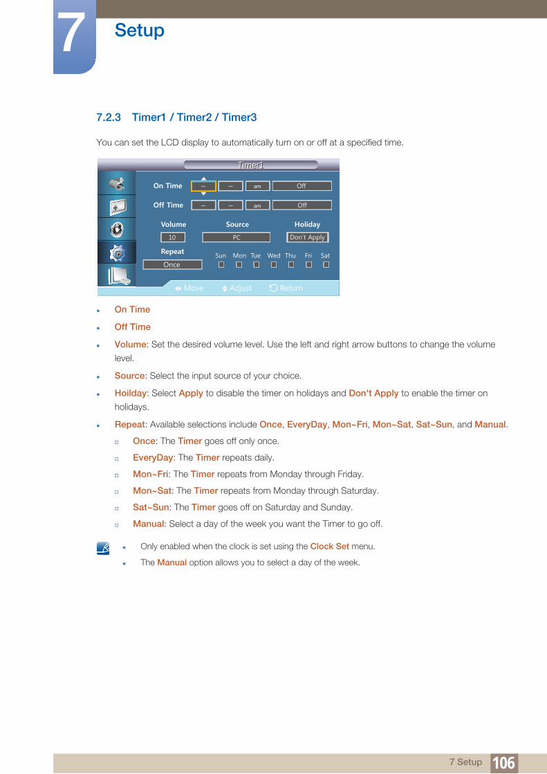
Setup7
7.2.3 Timer1 / Timer2 / Timer3You can set the LCD display to automatically turn on or off at a specified time.
On Time
Off Time
Volume: Set the desired volume level. Use the left and right arrow buttons to change the volume
level.
Source: Select the input source of your choice.
Hoilday: Select Apply to disable the timer on holidays and Don't Apply to enable the timer on
holidays.
Repeat: Available selections include Once, EveryDay, Mon~Fri, Mon~Sat, Sat~Sun, and Manual.
Once: The Timer goes off only once.
EveryDay: The Timer repeats daily.
Mon~Fri: The Timer repeats from Monday through Friday.
Mon~Sat: The Timer repeats from Monday through Saturday.
Sat~Sun: The Timer goes off on Saturday and Sunday.
Manual: Select a day of the week you want the Timer to go off.
Only enabled when the clock is set using the Clock Set menu.
The Manual option allows you to select a day of the week.
-- am--
-- am--
1067 Setup

Setup7
7.2.4 Holiday ManagementTimer will be disabled during a period specified as a holiday.
Setting Holiday Management
Add: Specify the period you want to add as a holiday.
Delete Selected: You can delete selected holidays.
Only enabled when registered holidays are selected.
More than one holiday can be selected and deleted.
Delete All: You can delete all the registered holidays.
7.3 Menu Transparency
MENU Setup Menu Transparency ENTER
Change the transparency of the background of the OSD.
01/01
O m
1077 Setup

Setup7
7.4 Safety LockMENU Setup Safety Lock ENTER
7.4.1 Change PIN
The password can be changed.
The preset password for the LCD Display is "0000".
If you forgot your password, press the remote buttons INFO EXIT MUTE to reset the password
to "0000."
7.4.2 Lock
This is the function that locks the OSD in order to keep the current settings or to prevent others from
adjusting the settings.
Selecting Lock On will enable Lock Off. To disable the Lock function, enter the password for Lock Off.
O m
..
..
1087 Setup

Setup7
7.5 Energy SavingMENU Setup Energy Saving ENTER
This feature adjusts the power consumption of the unit in order to save energy.
Off / On
7.6 Video Wall
MENU Setup Video Wall ENTER
Customize the layout of multiple displays that are connected to form a video wall. In addition, display part
of a whole picture or repeat the same picture on each of the connected multiple displays. To display
multiple images, refer to MDC Help or the MagicInfo user guide. Some models may not support the
MagicInfo function.
If more than four displays are connected horizontally and vertically, it is recommended that you use an
input resolution of XGA (1024 x 768) level or higher to prevent a dark picture due to degradation in the
contrast or color intensity.
7.6.1 Video Wall
You can activate or deactivate Video Wall.
To organize a video wall, select On.
O m
O m
1097 Setup

Setup7
7.6.2 FormatSelect a format to display images on multiple displays.
Full: Display images in full screen.
Natural: Display images at the original resolution without enlarging or reducing.
The Screen Position option is only enabled when Video Wall is set to On.
7.6.3 Horizontal
This function automatically divides the screen according to the specified number of horizontal displays.
Enter the number of horizontally arranged displays. The horizontal screen will automatically be divided
according to the number entered. A maximum of 15 displays can be assigned to the horizontal
arrangement.
The screen can be divided into a maximum of 100 screens (horizontal and vertical screens multiplied). For example, if the horizontal arrangement is set to 15, a maximum of 6 displays can be assigned to the vertical arrangement. Conversely, if the vertical arrangement is set to 15, a maximum of 6 displays can be assigned to the horizontal arrangement.
The Screen Position option is only enabled when Video Wall is set to On.
1107 Setup

Setup7
7.6.4 VerticalThis function automatically divides the screen according to the specified number of vertical displays. Enter
the number of vertically arranged displays. The vertical screen will automatically be divided according to
the number entered. A maximum of 15 displays can be assigned to the vertical arrangement.
The screen can be divided into a maximum of 100 screens (horizontal and vertical screens multiplied). For example, if the horizontal arrangement is set to 15, a maximum of 6 displays can be assigned to the vertical arrangement. Conversely, if the vertical arrangement is set to 15, a maximum of 6 displays can be assigned to the horizontal arrangement.
The Screen Position option is only enabled when Video Wall is set to On.
7.6.5 Screen Position
You can customize the arrangement of split screens by moving displays identified with a number using
the Screen Position function.
Select Screen Position to display the arrangement of displays (identified with a number) specified
according to the Horizontal or Vertical settings. To customize the arrangement, move a number (display)
using the direction buttons on the remote control and press [ ].
A maximum of 100 displays can be arranged in Screen Position.
The Screen Position option is only enabled when Video Wall is set to On.
The Screen Position window is only displayed when Horizontal and Vertical are configured.
1117 Setup

Setup7
7.7 Safety ScreenMENU Setup Safety Screen ENTER
The Safety Screen function is used to prevent afterimages that may appear when a still picture is
displayed on the screen over a long time.
This function is not available when the power is turned off.
7.7.1 Pixel Shift
Pixel Shift
To prevent after-images on the screen, you can use this function to have pixels move on the LCD in the
horizontal or vertical direction.
Off / On
Horizontal
Sets how many pixels the screen moves horizontally.
Five adjustment levels: 0, 1, 2, 3, and 4.
Vertical
Sets how many pixels the screen moves vertically.
Five adjustment levels: 0, 1, 2, 3, and 4.
Time
Set the time interval for performing the horizontal or vertical movement, respectively.
O m
1 1 2
7 Setup

Setup7
7.7.2 TimerYou can set the timer for Screen Burn Protection.
Timer
If you start the operation to erase any residual image, the operation will be performed for the set period of
time and then automatically finish.
Off / On
Mode
You can change the Safety Screen Type.
Bar / Eraser / Pixel
Period
Use this function to set the execution period for each mode set in the timer.
Time
Within the set period of time specify a time for execution.
Mode - Bar, Eraser, Pixel : 10~50 sec
1137 Setup

Setup7
7.7.3 BarThis function prevents after-images on the screen by moving long black and white vertical lines.
7.7.4 Eraser
This function prevents after-images on the screen by moving a rectangular pattern.
7.7.5 Pixel
This function prevents after-images by moving many pixels on the screen.
1147 Setup

Setup7
7.7.6 Side GraySelect the brightness of the grey for the screen background.
Off / Light / Dark
7.8 Resolution Select
MENU Setup Resolution Select ENTER
When the picture is not displayed properly on the screen when setting the graphics card resolution of the
computer to 1024 x 768 @ 60Hz, 1280 x 768 @ 60Hz, 1360 x 768@ 60Hz or 1366 x 768 @ 60Hz, by
using this function(Resolution Select), you can have the picture displayed on the screen in the specified
resolution.
Selecting the menu is only allowed when the graphics resolution is set to 1024 x 768 @ 60Hz, 1280
x 768 @ 60Hz, 1360 x 768 @ 60Hz or 1366 x 768 @ 60Hz.
O m
1157 Setup

Setup7
7.9 Power On AdjustmentMENU Setup Power On Adjustment ENTER
You can set the warm-up time for the screen to turn on after the power button is pressed. (Range: 0 – 50
seconds)
A warm-up time that is too short may damage the product due to overvoltage.
7.10 OSD Rotation
MENU Setup OSD Rotation ENTER
You can rotate and display the menu window in portrait mode when the product is in portrait orientation.
Landscape / Portrait
O m
O m
1167 Setup

Setup7
7.11 Advanced SettingsMENU Setup Advanced Settings ENTER
Configures the settings more elaborately.
7.11.1 Fan & Temperature
Protects the product by detecting the fan speed and internal temperature.
Fan Control
Selects auto or manual for the fan speed settings.
Auto / Manual
Fan Speed Setting
Sets the fan speed within a range of 0 and 100.
Enabled when Fan Control is set to Manual.
O m
1177 Setup

Setup7
Temperature ControlDetects the product's internal temperature and specifies the desired temperature.
The product is set to 77 °C by default.
The picture will be dimmed if the temperature exceeds the specified temperature, and the product will automatically power off to prevent overheating if the temperature keeps rising.
It is best to use the product at temperatures 75 - 80 °C (based on ambient temperature of 40 °C).
Refer to "Specifications" herein for details about operating conditions.
Current Temperature: Shows the current temperature of the product.
1187 Setup

Setup7
7.11.2 Auto PowerEnables or disables Auto Power for the product.
Off / On
When Auto Power is On, the product will power on automatically as soon as it is connected to power.
7.11.3 Button Lock
Locks or unlocks the monitor control buttons on the product.
Off / On
7.11.4 User Auto Color
Auto Color
Automatically adjusts the colors.
Reset
Resets the color settings.
1197 Setup

Setup7
7.11.5 Standby ControlSets the standby mode, which will be activated when no input signal is detected.
Off
A message will read <No Signal> if no input signal is detected.
On
Power-saving mode will be activated if no input signal is detected.
Auto
When no input signal is detected,
Power-saving mode will be activated if an external device is connected.
A message will read <No Signal> if no external device is connected.
This function at <Auto> doesn't work at HDMI source.
1207 Setup

Setup7
7.11.6 Lamp ScheduleAdjusts the luminance to a user-specified value at a specified time.
Off / On
Only enabled when the clock is set using the Clock Set menu.
7.11.7 OSD Display
Displays or hides a menu item on the screen.
Source OSD
Off / On
Not Optimum Mode OSD
Off / On
No Signal OSD
Off / On
MDC OSD
Off / On
1217 Setup

Setup7
7.11.8 Software UpgradePerforms a software upgrade.
1 Connect the product to a computer via a digital signal such as DVI or HDMI. Click the BMP image
file converted from an SW code. The image below will appear on the screen of the product.
2 While a BMP image onto which the software code has been converted is displayed on the screen,
select Software Upgrade.
When there are two or more BMP images, they are displayed on the screen using a slideshow.
It is recommended that the playback interval between two BMP images in the slideshow should be one second. The image extraction probability will decrease with other playback intervals.
A BMP image might not be extracted if it is covered by another image (for example, the mouse pointer).
3 If a more recent version than the current software version is detected, you will be asked whether to
upgrade the current software. If you select <Yes>, the upgrade is performed.
4 When the software upgrade is completed, the product is turned off and on automatically.
This only operates with a digital signal, such as in DVI, HDMI mode. (The input resolution must be identical to the panel resolution.)
In HDMI modes, the timing values used for both the PC and product are only supported if the Edit Name is set to PC or DVI PC.
This is only supported if the Size is set to 16:9.
1227 Setup

Setup7
7.12 Setup ResetMENU Setup Setup Reset ENTER
This option returns the current settings under system to the default factory settings.
7.13 Reset All
MENU Setup Reset All ENTER
This option returns all the current settings for a display to the default factory settings.
O m
O m
1237 Setup

8 Tr
oubleshooting Guide8.1 Requirements Before Contacting Samsung Customer Service Center
8.1.1 Testing the Product
Before calling Samsung Customer Service Center, test your product as follows. If the problem persists,
contact Samsung Customer Service Center.
Check if your product is operating normally by using the product test function.
If the screen remains blank while the power LED blinks even when the product is correctly connected to
a PC, perform product testing.
1 Power off both the PC and product.
2 Disconnect all the cables from the product.
3 Power on the product.
4 If "No Signal" is displayed, the product is operating normally.
If the screen remains blank, check the PC system, video controller and cable.
8.1.2 Checking the Resolution and Frequency
"Not Optimum Mode" will briefly be displayed if a mode that exceeds a supported resolution is selected
(refer to Supported Resolutions).
8.1.3 Check the followings.
Installation issue
The screen keeps switching on and off. Check the cable connection between the product and PC, and ensure the connection is secure.
("2.2 Connecting and Using a PC")
Blank spaces are found on all four sides of the screen when an HDMI or HDMI-DVI cable is connected to the product and PC.
The blank spaces found on the screen have nothing to do with the product.
Blank spaces on the screen are caused by the PC or graphics card. To resolve the problem, adjust the screen size in the HDMI or DVI settings for the graphics card.
If the graphics card settings menu does not have an option to adjust the screen size, update the graphics card driver to the latest version.
(Please contact the graphics card or computer manufacturer for further details about how to adjust the screen settings.)
1248 Troubleshooting Guide

Troubleshooting Guide8
Screen issueThe power LED is off. The screen will not switch on.
Make sure that the power cord is connected.
("2.2 Connecting and Using a PC")
"No Signal" is displayed on the screen (refer to "Connecting to a PC").
Check that the product is connected correctly with a cable
("2.2 Connecting and Using a PC")
Check that the device connected to the product is powered on.
"Not Optimum Mode" is displayed. This message is displayed when a signal from the graphics card exceeds the product's maximum resolution and frequency.
Refer to the Standard Signal Mode Table and set the maximum resolution and frequency according to the product specifications.
The images on the screen look distorted. Check the cable connection to the product
("2.2 Connecting and Using a PC")
The screen is not clear. The screen is blurry. Remove any accessories (video extension cable, etc) and try again.
Set the resolution and frequency to the recommended level.
The screen appears unstable and shaky. Check that the resolution and frequency of the PC and graphics card are set within a range compatible with the product. Then, change the screen settings if required by referring to the Additional Information on the product menu and the Standard Signal Mode Table.
There are shadows or ghost images left on the screen.
The screen is too bright. The screen is too dark.
Adjust Brightness and Contrast.
Screen color is inconsistent. Go to Picture and adjust the Colo(u)r Temp. settings.
The colors on the screen have a shadow and are distorted.
Go to Picture and adjust the Colo(u)r Temp. settings.
White does not really look white. Go to Picture and adjust the Colo(u)r Temp. settings.
There is no image on the screen and the power LED blinks every 0.5 to 1 second.
The product is in power-saving mode.
Press any key on the keyboard or move the mouse to return to the previous screen.
1258 Troubleshooting Guide

Troubleshooting Guide8
Sound issueThere is no sound. Check the connection of the audio cable or adjust the volume
("2.2 Connecting and Using a PC")
Check the volume.
The volume is too low. Adjust the volume.
If the volume is still low after turning it up to the maximum level, adjust the volume on your PC sound card or software program.
Remote control issue
The remote control does not work. Make sure that the batteries are correctly in place (+/-).
Check if the batteries are flat.
Check for power failure.
Make sure that the power cord is connected.
Check for any special lighting or neon signs switched on in the vicinity.
Source device issue
A beeping sound is heard when my PC is booting.
If a beeping sound is heard when your PC is booting, have your PC serviced.
1268 Troubleshooting Guide

Troubleshooting Guide8
8.2 Q & ARefer to the user manual for your PC or graphics card for further instructions on adjustment.
Question Answer
How can I change the frequency?
Set the frequency on your graphics card.
"Windows XP": Go to Control Panel Appearance and Themes
Display Settings Advanced Monitor and adjust the
frequency in Monitor Settings.
"Windows ME/2000": Go to Control Panel Display Settings
Advanced Monitor and adjust the frequency in Monitor
Settings.
"Windows Vista": Go to Control Panel Appearance and
Personalization Personalize Display Settings Advanced
Settings Monitor and adjust the frequency in Monitor Settings.
"Windows 7": Go to Control Panel Appearance and
Personalization Display Adjust resolution Advanced
Settings Monitor and adjust the frequency in Monitor Settings.
How can I change the resolution?
"Windows XP": Go to Control Panel Appearance and Themes
Display Settings and adjust the resolution.
"Windows ME/2000": Go to Control Panel Display Settings
and adjust the resolution.
"Windows Vista": Go to Control Panel Appearance and
Personalization Personalize Display Settings and adjust the
resolution.
"Windows 7": Go to Control Panel Appearance and
Personalization Display Adjust Resolution and adjust the
resolution.
How do I set power-saving mode?
Windows XP: Set power-saving mode in Control Panel
Appearance and Themes Display Screen Saver Settings or
BIOS SETUP on the PC.
Windows ME/2000: Set power-saving mode in Control Panel
Display Screen Saver Settings or BIOS SETUP on the PC.
Windows Vista: Set power-saving mode in Control Panel
Appearance and Personalization Personalize Screen Saver
Settings or BIOS SETUP on the PC.
Windows 7: Set power-saving mode in Control Panel
Appearance and Personalization Personalize Screen Saver
Settings or BIOS SETUP on the PC.
1278 Troubleshooting Guide

9 S
pecifications9.1 General
Power Supply : This product uses 100 to 240V. Refer to the label at the back of the product as the
standard voltage can vary in different countries.
Plug-and-Play : This monitor can be installed and used with any Plug-and-Play compatible
systems. Two-way data exchange between the monitor and PC system optimizes the monitor
settings. Monitor installation takes place automatically. However, you can customize the
installation settings if desired.
Due to the nature of the manufacturing of this product, approximately 1 pixel per million (1ppm)
may appear brighter or darker on the panel. This does not affect product performance.
Model Name UD22B
Panel
Size 21.6 inches (54 cm)
Display area387.36 mm (H) x 387.36 mm (V)
15.3 inches (H) x 15.3 inches (V)
Display Color 16.7M
Dimensions (W x H x D) / Weight
(without stand)
393.3 x 393.3 x 81.5 mm / 6.5 kg
15.5 x 15.5 x 3.2 inches / 14.3 Ibs
VESA Mounting Interface 300 x 300 mm (11.8 x 11.8 inches)
Synchronization
Horizontal Frequency
30 ~ 81 KHz
Vertical Frequency
56 ~ 85 Hz
Resolution
Optimum resolution
960 x 960 @ 60 Hz
Maximum resolution
1920 x 1080 @ 60 Hz
Maximum Pixel Clock 148.5 MHz (Analog,Digital)
Signal connectors
Input : DVI IN, HDMI IN, DP IN, IR/AMBIENT SENSOR IN, RJ45 MDC, RS232C IN
Output : DVI OUT(LOOPOUT), AUDIO OUT, IR OUT, RS232C OUT
Environmental considerations
OperatingTemperature : 32 ˚F ~ 104 ˚F (0 ˚C ~ 40 ˚C)
Humidity : 10 % ~ 80 %, non-condensing
StorageTemperature : -4 ˚F ~ 113 ˚F (-20 ˚C ~ 45 ˚C)
Humidity : 5 % ~ 95 %, non-condensing
1289 Specifications

Specifications9
This device is a Class A digital apparatus.
(USA only)
Dispose unwanted electronics through an approved recycler.
To find the nearest recycling location, go to our website:
www.samsung.com/recyclingdirect or call, (877) 278 - 0799
1299 Specifications

Specifications9
9.2 PowerSaverThe power-saving function of this product reduces power consumption by switching off the screen and
changing the color of the power LED if the product is not used for a specified period of time. The power
is not turned off in power-saving mode. To switch the screen back on, press any key on the keyboard or
move the mouse. Power-savign mode only functions when the product is connected to a PC with a
power-saving function.
The displayed power consumption level can vary in different operating conditions or when settings are changed.
SOG(Sync On Green) is not supported.
To reduce the power consumption to 0, turn off the switch at the back or disconnect the power cord. Disconnect the power cable if you will not be using the product for an extended period of time (during vacation, etc.).
PowerSaverNormal Operation
Power saving modePower off
(Power Button off)Rating Typical
Power Indicator On Blinking Off
Power Consumption 65 W 67 W less than 0.5 W less than 0.5 W
1309 Specifications

Specifications9
9.3 Preset Timing ModesThis product can be set to only one resolution for each screen size to obtain the optimum picture
quality due to the nature of the panel. Using a resolution other than the specified resolution may
degrade the picture quality. To avoid this, it is recommended that you select the optimum resolution
specified for your product.
Check the frequency when you exchange a CDT product (connected to a PC) for an LCD product. If
the LCD product does not support 85Hz, change the vertical frequency to 60Hz using the CDT
product before you exchange it with the LCD product.
The screen will automatically be adjusted if a signal that belongs to the following standard signal modes is
transmitted from your PC. If the signal transmitted from the PC does not belong to the standard signal
modes, the screen may be blank with the power LED on. In such a case, change the settings according
to the following table by referring to the graphics card user manual.
ResolutionHorizontal Frequency
(kHz)
Vertical Frequency
(Hz)
Pixel Clock (MHz)
Sync Polarity
(H/V)
IBM, 640 x 480 31.469 59.940 25.175 -/-
IBM, 720 x 400 31.469 70.087 28.322 -/+
MAC, 640 x 480 35.000 66.667 30.240 -/-
MAC, 832 x 624 49.726 74.551 57.284 -/-
MAC, 1152 x 870 68.681 75.062 100.000 -/-
VESA, 640 x 480 37.861 72.809 31.500 -/-
VESA, 640 x 480 37.500 75.000 31.500 -/-
VESA, 800 x 600 37.879 60.317 40.000 +/+
VESA, 800 x 600 48.077 72.188 50.000 +/+
VESA, 800 x 600 46.875 75.000 49.500 +/+
VESA, 960 x 960 59.731 59.971 75.500 -/+
VESA, 1024 x 768 48.363 60.004 65.000 -/-
VESA, 1024 x 768 56.476 70.069 75.000 -/-
VESA, 1024 x 768 60.023 75.029 78.750 +/+
VESA, 1280 x 1024 63.981 60.020 108.000 +/+
VESA, 1280 x 1024 79.976 75.025 135.000 +/+
VESA, 1920 x 1080(RB) 66.587 59.934 138.500 +/-
1319 Specifications

Specifications9
Horizontal Frequency
The time required to scan a single line from the left to the right side of the screen is called a
horizontal cycle. The reciprocal number of a horizontal cycle is called horizontal frequency.
Horizontal frequency is measured in kHz.
Vertical Frequency
The product displays a single image multiple times per second (like a fluorescent light) to display
what the viewer sees. The rate of a single image being displayed repeatedly per second is called
vertical frequency or refresh rate. Vertical frequency is measured in Hz.
1329 Specifications

A
ppendixContact SAMSUNG WORLDWIDE
If you have any questions or comments relating to Samsung products, please contact the SAMSUNG
customer care center.
NORTH AMERICA
U.S.A 1-800-SAMSUNG (726-7864) http://www.samsung.com
CANADA 1-800-SAMSUNG (726-7864) http://www.samsung.com/ca
http://www.samsung.com/ch_fr (French)
MEXICO 01-800-SAMSUNG (726-7864) http://www.samsung.com
LATIN AMERICA
ARGENTINA 0800-333-3733 http://www.samsung.com
BRAZIL 0800-124-4214004-0000
http://www.samsung.com
BOLIVIA 800-10-7260 http://www.samsung.com
CHILE 800-SAMSUNG (726-7864)
From mobile 02-482 82 00
http://www.samsung.com
COLOMBIA 01-8000112112 http://www.samsung.com
COSTA RICA 0-800-507-7267 http://www.samsung.com
DOMINICA 1-800-751-2676 http://www.samsung.com
ECUADOR 1-800-10-7267 http://www.samsung.com
EL SALVADOR 800-6225 http://www.samsung.com
GUATEMALA 1-800-299-0013 http://www.samsung.com
HONDURAS 800-27919267 http://www.samsung.com
JAMAICA 1-800-234-7267 http://www.samsung.com
NICARAGUA 00-1800-5077267 http://www.samsung.com
PANAMA 800-7267 http://www.samsung.com
PERU 0-800-777-08 http://www.samsung.com
PUERTO RICO 1-800-682-3180 http://www.samsung.com
TRINIDAD & TOBAGO 1-800-SAMSUNG (726-7864) http://www.samsung.com
VENEZUELA 0-800-100-5303 http://www.samsung.com
133 Appendix

Appendix
EUROPE
ALBANIA 42 27 5755 http://www.samsung.com
AUSTRIA 0810 - SAMSUNG (7267864, € 0.07/min)
http://www.samsung.com
BELGIUM 02-201-24-18 http://www.samsung.com/be (Dutch)
http://www.samsung.com/be_fr (French)
BOSNIA 05 133 1999 http://www.samsung.com
BULGARIA 07001 33 11 http://www.samsung.com
CROATIA 062 SAMSUNG (062 726 7864) http://www.samsung.com
CZECH 800 - SAMSUNG (800-726786) http://www.samsung.com
DENMARK 70 70 19 70 http://www.samsung.com
FINLAND 030 - 6227 515 http://www.samsung.com
FRANCE 01 48 63 00 00 http://www.samsung.com
GERMANY 01805 - SAMSUNG (726-7864,€ 0,14/Min)
http://www.samsung.com
CYPRUS From landline : 8009 4000 http://www.samsung.com
GREECE From landline : 80111-SAMSUNG (7267864)
From landline & mobile : (+30)
210 6897691
http://www.samsung.com
HUNGARY 06-80-SAMSUNG (726-7864) http://www.samsung.com
ITALIA 800-SAMSUNG (726-7864) http://www.samsung.com
KOSOVO +381 0113216899 http://www.samsung.com
LUXEMBURG 261 03 710 http://www.samsung.com
MACEDONIA 023 207 777 http://www.samsung.com
MONTENEGRO 020 405 888 http://www.samsung.com
NETHERLANDS 0900 - SAMSUNG (0900-7267864) (€ 0,10/Min)
http://www.samsung.com
NORWAY 815-56 480 http://www.samsung.com
POLAND 0 801-1SAMSUNG (172-678)+48 22 607-93-33
http://www.samsung.com
PORTUGAL 808 20 - SAMSUNG (808 20
7267)
http://www.samsung.com
Samsung Electronics Czech and Slovak, s.r.o., Oasis Florenc, Sokolovská 394/17, 180 00, Praha 8
134 Appendix
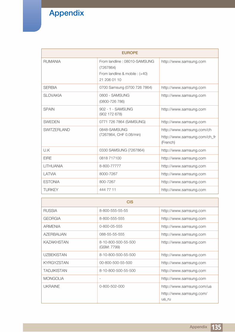
Appendix
RUMANIA From landline : 08010-SAMSUNG
(7267864)
From landline & mobile : (+40)
21 206 01 10
http://www.samsung.com
SERBIA 0700 Samsung (0700 726 7864) http://www.samsung.com
SLOVAKIA 0800 - SAMSUNG
(0800-726 786)
http://www.samsung.com
SPAIN 902 - 1 - SAMSUNG (902 172 678)
http://www.samsung.com
SWEDEN 0771 726 7864 (SAMSUNG) http://www.samsung.com
SWITZERLAND 0848-SAMSUNG (7267864, CHF 0.08/min)
http://www.samsung.com/ch
http://www.samsung.com/ch_fr (French)
U.K 0330 SAMSUNG (7267864) http://www.samsung.com
EIRE 0818 717100 http://www.samsung.com
LITHUANIA 8-800-77777 http://www.samsung.com
LATVIA 8000-7267 http://www.samsung.com
ESTONIA 800-7267 http://www.samsung.com
TURKEY 444 77 11 http://www.samsung.com
CIS
RUSSIA 8-800-555-55-55 http://www.samsung.com
GEORGIA 8-800-555-555 http://www.samsung.com
ARMENIA 0-800-05-555 http://www.samsung.com
AZERBAIJAN 088-55-55-555 http://www.samsung.com
KAZAKHSTAN 8-10-800-500-55-500 (GSM: 7799)
http://www.samsung.com
UZBEKISTAN 8-10-800-500-55-500 http://www.samsung.com
KYRGYZSTAN 00-800-500-55-500 http://www.samsung.com
TADJIKISTAN 8-10-800-500-55-500 http://www.samsung.com
MONGOLIA - http://www.samsung.com
UKRAINE 0-800-502-000 http://www.samsung.com/ua
http://www.samsung.com/ua_ru
EUROPE
135 Appendix

Appendix
BELARUS 810-800-500-55-500 http://www.samsung.com
MOLDOVA 00-800-500-55-500 http://www.samsung.com
ASIA PACIFIC
AUSTRALIA 1300 362 603 http://www.samsung.com
NEW ZEALAND 0800 SAMSUNG (0800 726 786) http://www.samsung.com
CHINA 400-810-5858 http://www.samsung.com
HONG KONG (852) 3698 - 4698 http://www.samsung.com/hk
http://www.samsung.com/hk_en/
INDIA 1800 1100 11
3030 8282
1800 3000 8282
1800 266 8282
http://www.samsung.com
INDONESIA 0800-112-8888021-5699-7777
http://www.samsung.com
JAPAN 0120-327-527 http://www.samsung.com
MALAYSIA 1800-88-9999 http://www.samsung.com
PHILIPPINES 1-800-10-SAMSUNG (726-7864) for PLDT
1-800-3-SAMSUNG (726-7864) for Digitel
1-800-8-SAMSUNG (726-7864) for Globe
02-5805777
http://www.samsung.com
SINGAPORE 1800-SAMSUNG (726-7864) http://www.samsung.com
THAILAND 1800-29-3232
02-689-3232
http://www.samsung.com
TAIWAN 0800-329-999
0266-026-066
http://www.samsung.com
VIETNAM 1 800 588 889 http://www.samsung.com
MIDDlE EAST
IRAN 021-8255 http://www.samsung.com
OMAN 800-SAMSUNG (726-7864) http://www.samsung.com
KUWAIT 183-2255 http://www.samsung.com
BAHRAIN 8000-4726 http://www.samsung.com
CIS
136 Appendix

Appendix
EGYPT 08000-726786 http://www.samsung.com
JORDAN 800-22273 http://www.samsung.com
MOROCCO 080 100 2255 http://www.samsung.com
SAUDI ARABIA 9200-21230 http://www.samsung.com
U.A.E 800-SAMSUNG (726-7864) http://www.samsung.com
AFRICA
CAMEROON 7095- 0077 http://www.samsung.com
COTE D'LVOIRE 8000 0077 http://www.samsung.com
GHANA 0800-10077
0302-200077
http://www.samsung.com
KENYA 0800 724 000 http://www.samsung.com
NIGERIA 0800-726-7864 http://www.samsung.com
SENEGAL 800-00-0077 http://www.samsung.com
SOUTH AFRICA 0860-SAMSUNG (726-7864) http://www.samsung.com
TANZANIA 0685 88 99 00 http://www.samsung.com
UGANDA 0800 300 300 http://www.samsung.com
MIDDlE EAST
137 Appendix

Appendix
Responsibility for the Pay Service (Cost to Customers)
When the service is requested, in spite of in warranty, we may charge you for a visit from a service
technician in the following cases.
Not a product defect
Cleaning of the product, Adjustment, Explanation, Re-installation and etc.
If a service technician gives instructions on how to use product or simply adjusts options without
disassembling product.
If a defect is caused by external environmental factors (Internet, Antenna, Wired Signal, etc.)
If a product is reinstalled or devices are connected additionally after installing the purchased product
for the first time.
If a product is reinstalled to move to a different spot or to move to a different house.
If customer requests instructions on how to use because of another company's product.
If customer requests instructions on how to use the network or another company's program.
If customer requests software installation and setup for the product.
If a service technician removes/cleans dusts or foreign materials inside of the product.
If customer requests an installation additionally after purchasing a product through home-shopping
or online.
A Product damage caused by customer's fault
Product damage caused by customer's mishandling or wrong repair
If a product damage is caused by;
External impact or drop.
Use of supplies or separatly sold product unspecified by Samsung.
Repair from a person besides an engineer of outsourcing service company or partner of Samsung
Electronics Co., Ltd.
Remodeling or repairing the product by customer.
Using it with incorrect voltage or non-authorised electrical connections.
Not following the "cautions" in User Manual.
Others
If product fails by natural disaster. (lightning, fire, earthquake, flood damage, etc)
If consumable components are all used up. (Battery, Toner, Fluorescent lights, Head, Vibrator,
Lamp, Filter, Ribbon, etc.)
If customer requests a service in case the product has no defect, service fee may be charged. So
please read User Manual first.
138 Appendix

Appendix
Optimum Picture Quality and Afterimage Burn-in Prevention
Optimum Picture Quality
To enjoy the optimum picture quality, go to Control Panel on your PC and adjust the resolution and
refresh rate as follows. The picture quality of TFT-LCDs may degrade if the optimum resolution is not
selected.
Resolution: 960 x 960
Vertical frequency (refresh rate): 56 ~ 85 Hz
Due to the nature of the manufacturing of this product, approximately 1 pixel per million (1ppm) may
be brighter or darker on the panel. This does not affect product performance.
The number of sub-pixels by panel type: 2,764,800
Run "Auto Adjustment" to improve the picture quality. If noise is still found even after auto
adjustment, adjust Coarse or Fine.
Leaving the screen fixed on a stationary image for an extended period of time may cause afterimage
burn-in or defective pixels.
Activate power-saving mode or a dynamic screen saver if you will not be using the product for
an extended period of time.
Unlike CDT monitors, TFT-LCD monitors (due to the nature of the panel) can be set to only one
resolution to obtain the optimum picture quality. Therefore, setting a resolution other than the
specified resolution may degrade the picture quality. To avoid this, it is recommended that you select
the optimum resolution specified for your monitor.
139 Appendix

Appendix
Prevention of Afterimage Burn-in
What is afterimage burn-in?
Afterimage burn-in should not occur when the LCD panel is operating normally. Normal operation refers
to a continuously changing video pattern. If the LCD panel displays a fixed pattern for an extended period
of time (more than 12 hours), a slight voltage difference may occur between the electrodes in pixels that
control the liquid crystals.
Such a voltage difference between electrodes increases with time and makes the liquid crystals thinner.
When this occurs, a previous image can remain on the screen when the pattern changes. To prevent this,
the accumulated voltage difference should be reduced.
Powering Off, Screen Saver and Power Saving Mode
Power off the product for 4 hours after using it for 20 hours.
Black Matrix
Source Drain
Data Bus-Line
Gate Pixel Electrode (ITO)Storage Capaccitor (Cs)
Color-FilterCommon Electrode (ITO)
140 Appendix

Appendix
Power off the product for 2 hours after using it for 12 hours.
Go to Display Properties > Power Supply on your PC and set the product to power off as
required.
Using a screen saver is recommended.
It is best to use a single-color or moving-image screen saver.
Regular color Change
Use 2 colors
Switch between 2 colors every 30 minutes as shown above.
Avoid combinations of a text color and background color of contrasting brightness.
Avoid using grey as it may contribute to afterimage burn-in.
Avoid using colors of contrasting brightness (black and white; grey).
Regular Text color Change
Use bright colors of similar brightness.
Interval: Change text color and background color every 30 minutes
Move and change text every 30 minutes as shown below.
Regularly display a moving image along with a logo.
Interval: Display a moving image along with a logo for 60 seconds after using for 4 hours.
The best way to protect the product from afterimage burn-in is switching the power off or
setting the PC or system to run a screen saver when not in use. Also, Warranty service may be
limited depending on instruction guide.
FLIGHT FLIGHTTIME TIME
OZ348
UA102 21:10
20:30OZ348
UA102 21:10
20:30
Type 1 Type 2
FLIGHT TIME
OZ348 20:30
:
:FLIGHT TIME
OZ348 20:30
:
:
FLIGHT TIME
OZ348 20:30
:
:
FLIGHT TIME
OZ348 20:30
:
:
FLIGHT TIME
OZ348 20:30
:
:
FLIGHT TIME
OZ348 20:30
:
:
FLIGHT TIME
OZ348
:
:
FLIGHT TIME
OZ348 20:30
:
:
[ Step 1 ] [ Step 2 ] [ Step 3 ]
20:30
141 Appendix

Appendix
Correct Disposal of This Product (Waste Electrical & Electronic Equipment)
Correct disposal of batteries in this product
(Applicable in countries with separate collection systems)
This marking on the product, accessories or literature indicates that the product and its electronic accessories (e.g. charger, headset, USB cable) should not be disposed of with other household waste at the end of their working life. To prevent possible harm to the environment or human health from uncontrolled waste disposal, please separate these items from other types of waste and recycle them responsibly to promote the sustainable reuse of material resources.
Household users should contact either the retailer where they purchased this product, or their local government office, for details of where and how they can take these items for environmentally safe recycling.
Business users should contact their supplier and check the terms and conditions of the purchase contract. This product and its electronic accessories should not be mixed with other commercial wastes for disposal.
(Applicable in countries with separate collection systems)
This marking on the battery, manual or packaging indicates that the batteries in this product should not be disposed of with other household waste at the end of their working life. Where marked, the chemical symbols Hg, Cd or Pb indicate that the battery contains mercury, cadmium or lead above the reference levels in EC Directive 2006/66. If batteries are not properly disposed of, these substances can cause harm to human health or the environment.
To protect natural resources and to promote material reuse, please separate batteries from other types of waste and recycle them through your local, free battery return system.
142 Appendix

Appendix
Terminology
OSD(On Screen Display)
On screen display (OSD) allows you to configure on-screen settings to optimize the picture quality as
required. It allows you to change the screen brightness, tint, size and many other settings using
menus displayed on the screen.
Gamma
The Gamma menu adjusts the grey scale that represents middle tones on the screen. Adjusting the
brightness brightens the whole screen, but adjusting Gamma only brightens the medium brightness.
Gray Scale
Scale refers to levels of color intensity that show variations of color change from darker areas to
brighter areas on the screen. Changes to the screen brightness are expressed with black and white
variation, and grey scale refers to the medium area between black and white. Changing the grey scale
through Gamma adjustment will change the medium brightness on the screen.
Scanning rate
Scanning rate, or refresh rate, refers to the frequency of screen refreshes. Screen data is transmitted
as it refreshes to display an image, although the refreshing is invisible to the naked eye. The number of
screen refreshes is called scanning rate and is measured in Hz. A scanning rate of 60Hz means that
the screen refreshes 60 times per second. The screen scanning rate depends on the performance of
the graphics cards in your PC and product.
Horizontal Frequency
Characters or images displayed on the product screen consist of numerous dots (pixels). Pixels are
transmitted in horizontal lines, which are then arranged vertically to create an image. The horizontal
frequency is measured in kHz and represents how many times horizontal lines per second are
transmitted and displayed on the product screen. A horizontal frequency of 85 means that the
horizontal lines that make up an image are transmitted 85 000 times per second, and the horizontal
frequency is indicated in 85kHz.
Vertical Frequency
One image is made of numerous horizontal lines. The vertical frequency is measured in Hz and
represents how many images can be created per second by those horizontal lines. A vertical
frequency of 60 means that an image is transmitted 60 times per second. The vertical frequency is
also called "refresh rate" and affects screen flicker.
143 Appendix

Appendix
Resolution
Resolution is the number of horizontal pixels and vertical pixels that form a screen. It represents the
level of display detail.
A higher resolution displays a greater amount of information on the screen and is suitable for
performing multiple tasks at the same time.
E.g. A resolution of 1920 x 1080 consists of 1,920 horizontal pixels (horizontal frequency) and 1,080
vertical lines (vertical resolution).
Plug & Play
The Plug & Play feature allows the automatic exchange of information between a product and PC to
produce an optimum display environment.
The product uses VESA DDC (international standard) to execute Plug & Play.
144 Appendix

Index
AAppendix 133
BBatteries 26
CChanging the Resolution 48
Connecting and Using a PC 46
Connecting to a Video Device 51
Contact SAMSUNG WORLDWIDE 133
Custom 93
EEco Solution 101, 102
Edit Name 90
Energy Saving 109
IItems sold separately 20
LLanguage 104
MMDC InstallationUninstallation 56
Menu Transparency 107
Mode 89, 92
PPC connection 46
Problem report 124
RRemote Control 25
Reset All 123
SSafety Lock 108
Safety Screen 112
Size 97
Sleep Timer 105
Source AutoSwitch Settings 91
Specifications 128
Standard 92
TTime 104
Index 145


